

Extreme off-road Unimog BlueTec 6
Technical Manual
August 2014 issue

Technical Manual
Technical Manual for extreme off-road Unimog BlueTec 6
The present Technical Manual serves Unimog Sales as an advisory
document. In addition to the basic vehicle version, special equipment is
also covered. Regarding the availability of standard and special equipment,
please refer to the applicable price lists. Subject to technical modifications
without notice. All rights reserved. Reprinting or reproduction in electronic
form, including excerpts, is prohibited and requires the approval of
Mercedes-Benz Special Trucks.
The latest changes and additions are available through our updates on
the Extranet at:
www.specialtrucks-extranet.com
Daimler AG
Mercedes-Benz Special Trucks
Sales & Marketing
August 2014 issue
Part A
Concept and sales reasoning
Part B
Technical data
Mercedes-Benz Special Trucks
1

Contents
Contents – Part A
Technical Manual
Overview of models and components ................................ 6
Product concept ................................................................... 7
Unimog model series in comparison .................................. 7
Extreme off-road capability ................................................ 8
The Unimog concept for extreme torsional flexibility ......... 9
Angle of approach / departure and ramp breakover angle 10
Fording capability ............................................................. 11
Optional equipment – fording capability .......................... 12
Frame ...................................................................................13
Frame concept ................................................................. 13
Optional equipment – frame ............................................ 15
Engine .................................................................................. 17
Engine concept ................................................................ 17
Drive clutch ...................................................................... 19
High-performance engine brake ....................................... 20
Engine control .................................................................. 20
Exhaust gas aftertreatment – BlueTec 6 .......................... 21
Exhaust emissions – limiting values ................................. 23
Regeneration .................................................................... 24
Radiator system .............................................................. 25
Optional equipment – engine ........................................... 26
Transmission .......................................................................27
Main transmission ............................................................ 27
Overview .......................................................................... 28
Engine management ........................................................ 29
Electronic Quick Reverse (EQR) ....................................... 30
Optional equipment – transmission ................................. 31
Axles ....................................................................................33
Portal axles ...................................................................... 33
Axle suspension ............................................................... 35
Torque tube technology .................................................... 36
Drive system .................................................................... 37
Single tyres ...................................................................... 38
Optional equipment – axles.............................................. 39
Brakes ..................................................................................43
Dual-circuit braking system .............................................. 43
4-channel ABS .................................................................. 44
Optional equipment – brakes ........................................... 45
Steering ...............................................................................46
Power steering ................................................................. 46
Optional equipment – steering ......................................... 47
2
Mercedes-Benz Special Trucks

Technical Manual
Contents
Cab exterior .........................................................................48
Cab concept ..................................................................... 48
Doors ............................................................................... 49
Safety ............................................................................... 50
Optional equipment – cab exterior ................................... 51
Cab interior .........................................................................54
Spaciousness ................................................................... 54
Controls ........................................................................... 55
Steering and gear-changing ............................................. 56
Instrumentation ............................................................... 57
Standard controls ............................................................ 58
Air conditioning, heating and ventilation system .............. 59
Optional equipment – cab interior .................................... 60
Auxiliary drives ...................................................................64
Location ........................................................................... 64
Optional equipment – power take-offs ............................. 65
Hydraulics ...........................................................................68
Overview of hydraulic system........................................... 68
Optional equipment – hydraulic system ........................... 69
Electrical system ................................................................71
Electronic networking ...................................................... 71
Optional equipment – electrical system ........................... 72
Attachment and mounting areas ......................................77
Locations of attachment and mounting areas .................. 77
Mounting areas ................................................................ 78
Optional equipment – mounting areas ............................. 79
Mercedes-Benz Special Trucks
3

Contents
Contents – Part B
Technical Manual
Engine .................................................................................. 86
Engine data – OM934 ..................................................... 86
Engine diagram – OM934 ................................................ 87
Filling capacities .............................................................. 88
Engine brake .................................................................... 88
Compressed air generation .............................................. 89
Transmission .......................................................................90
Main transmission ............................................................ 90
Clutch .............................................................................. 90
Vehicle speeds – U 4023 / U 5023 ................................. 91
Vehicle speed conversion factor ......................................92
Axles ....................................................................................93
Suspension ...................................................................... 93
Technical data on axles .................................................... 93
Technical data on U 4023 rims ........................................94
Technical data on U 5023 rims ........................................95
Brakes ..................................................................................96
Braking system ................................................................ 96
Cab exterior .........................................................................97
Exterior ............................................................................ 97
Cab interior .........................................................................98
Interior ............................................................................. 98
Auxiliary drives ...................................................................99
[N05] Engine PTO to rear, with flange .............................. 99
[N13]/[N16]/[N19] Transmission PTO ........................... 100
Hydraulics .........................................................................101
Technical data on single hydraulic system ..................... 101
Electrical system ..............................................................102
On-board electrical system ............................................ 102
Lights ............................................................................. 102
4
Mercedes-Benz Special Trucks

Technical Manual
Contents
Weights ..............................................................................103
Permissible load values .................................................. 103
Trailer operation ...............................................................104
Pin-type trailer hitch ....................................................... 104
Hook-type trailer hitch (not for civilian use) ...................104
Towing capacities – U 4023, model designation
437.427, 170 kW ........................................................... 105
Towing capacity U 5023, model designation
437.437, 170kW ........................................................... 106
Wheels/tyres ....................................................................107
Tyre availability ...............................................................107
Tyres (technical data) .....................................................108
Tyre load capacity ..........................................................109
Speed allocations ........................................................... 110
MPT (multi-purpose tyres) .............................................. 112
AS tyres ......................................................................... 114
Dimensions .......................................................................115
Technical drawing for U 4023 BlueTec 6,
model designation 437.427 ........................................... 115
Technical drawing for U 5023 BlueTec 6,
model designation 437.437 ........................................... 116
General information .........................................................117
Vehicle climbing resistance ............................................ 117
Trailer climbing resistance .............................................117
Tractive force diagram – U 4023 (8.8 t) .........................118
Tractive force diagram – U 4023 (10.3 t) ....................... 118
Tractive force diagram – U 5023 (14.1 t) ....................... 119
Tractive force diagram – U 5023 (14.5 t) ....................... 119
Mercedes-Benz Special Trucks
5

Overview of models and components Technical Manual
Overview of models and components
Model name Model designation Wheelbase
(mm)
U 4023 437.427 3850 OM934 170/231 4 7.5 / 8.0 / 8.8 / 9.8 / 10.3
U 5023 437.437 3850 OM934 170/231 4 12.5 / 12.7 / 13.0 / 14.1 / 14.5
Engine Output
(kW/hp)
No. of
cylinders
Permissible gross vehicle
weight: Variants (t)
6
Mercedes-Benz Special Trucks

Technical Manual
Product concept
Unimog model series in comparison
Product concept
Unimog Implement Carrier BlueTec 6
• Compact all-terrain Unimog implement carrier
• Vehicle type: tractor unit/truck
• Vehicle width: from 2.15 m
• Wheelbases: 2800 mm – 3900 mm
• Straight, dimensionally stable and weight-optimised
ladder-type frame
• Panoramic cab with large windscreen and
low instrument support
• 4+3 implement mounting areas
• Extensive hydraulics package
• Mechanical engine and transmission PTOs
• Permanent all-wheel drive, differential locks engageable
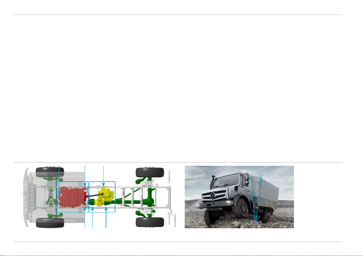
Extreme off-road Unimog BlueTec 6
• Extreme off-road Unimog chassis
• Vehicle type: truck chassis
• Vehicle width: from 2.3 m
• Wheelbase: 3850 mm
• Dropped, flexible and torsionally flexible frame
• Cab-behind-engine truck with raised windscreen
• Long body length for greater load volume
• Integrated hydraulics system available
• Mechanical engine and transmission PTOs
• Rear axle drive, all-wheel drive and differential locks engageable
Unimog Implement Carrier BlueTec 6 Extreme off-road Unimog BlueTec 6
Mercedes-Benz Special Trucks
7
Product concept Technical Manual
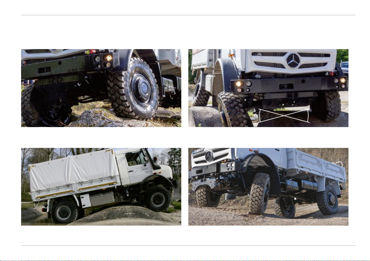
Extreme off-road capability
Feature
• Heavy-duty, torsionally flexible frame
• Portal axle with asymmetric differential arrangement
• Axle location via torque tube technology, coil springs and
transverse control arms
• Fording capability
• Atmospheric pressure equalisation of components
• Short frame overhangs at front and rear
• Low vehicle centre of gravity
• All-wheel drive and differential locks engageable and disengageable
via dog clutch while on the move
a
c
b
Advantage
• Good flexibility off-road on steep inclines and rough surfaces
• Large ground clearance when driving over obstacles
• Extreme diagonal torsional flexibility
• Central load application and bracing on gearbox
• Protection for drive shafts
• Enables fording of water to a depth of 80 cm (standard) /
120 cm [Z16]
• No excess pressure in components
• Large angle of approach/departure and ramp breakover angle
• High climbing and tipping angle
• High tractive power available at all times
• 100 % locking effect
• No interruption in tractive power, no stopping
U 4023 U 5023
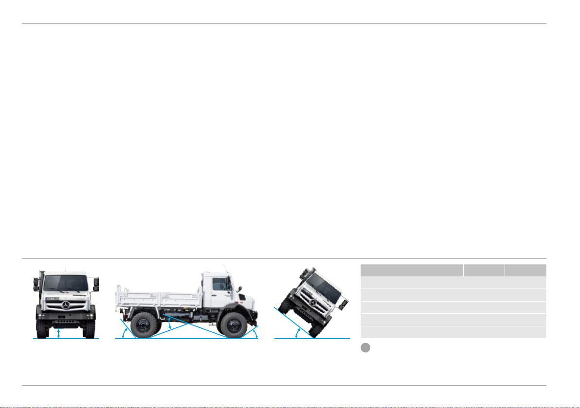
a) Ground clearance (mm) 410 460
b) Angle of approach (°) 42 46
c) Ramp breakover angle (°) 32 36
d) Angle of departure (°) 46 50
ed
e) Tipping angle (°) 38 38
i
Angle not dependent on load condition or tyres.
8 Mercedes-Benz Special Trucks
Technical Manual
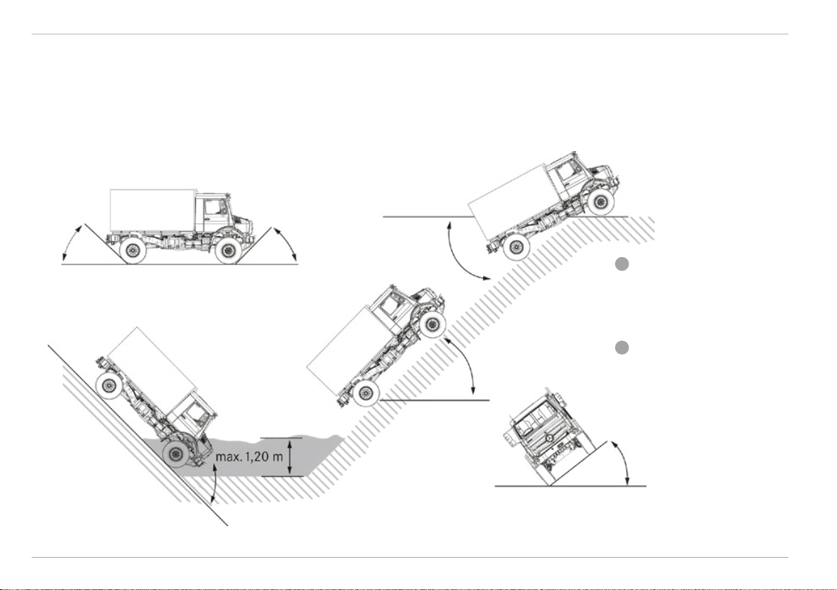
Product concept
The Unimog concept for extreme torsional flexibility
30°30°
Driving over obstacles optimised by asymmetric arrangement of the axle differentials Major axle articulation made possible by torque tube concept and coil springs
Driving over sharp crests possible thanks to large ramp breakover angle and
angle of approach/departure
Mercedes-Benz Special Trucks
3-point mounting of engine, gearbox and cab. Double 3-point body mounting
9
Product concept Technical Manual
Angle of approach / departure and ramp breakover angle
Figures shown are static values for the chassis of a U5023.
Ramp breakover angle
50° 46°
Angle of approach and departure
Approach
10
46°
Fording capability, approach angle
36°
45°
Slope angle
i
For the angles of the individual
vehicle models, please refer to the
dimensioned drawings in Section B.
Illustrations show 365/85 R20 tyres.
i
The permissible roll angle is 38 degrees
in static state (vehicle functional);
the dynamic limit is 16.5 degrees
(corresponding to 30 %).
38°
Tipping angle
Mercedes-Benz Special Trucks

Technical Manual
Fording capability
Product concept
Feature
• Torque tube technology
• Air intake pipe at level of cab roof
• Large ground clearance
• Fan with electronic viscous clutch, mechanically driven via
propeller shaft, raised
• Key components and electrical devices protected against
splashing water
Advantage
• Enables standard fording capability to 80 cm
• No permanent drive, fan remains operational
• No damage resulting from exposure to water
• No sagging of a V-belt
Standard fording capability to 80 cm
Mercedes-Benz Special Trucks
11

Product concept Technical Manual
Optional equipment – fording capability
Feature
[Z16] Special parts, fording capability
• Raised pressure compensating lines for axles, gearbox,
working gear range, torque tube, fuel tank, air drier,
solenoid valves, brake system, etc.
• Waterproof main headlights with central, raised ventilation
• New position for auxiliary heater [D6N]
Advantage
• Enable fording capability to 120 cm
• Atmospheric pressure compensation with vent lines from the
components prevents entry of water and fine sand
• No reduction in fording capability with optional auxiliary heater
i
Recommended special equipment:
• Double sealing of wheel hubs, for
operations in muddy conditions
[A27]
Special equipment, special parts for fording capability to
120cm [Z16]
12 Mercedes-Benz Special Trucks
Technical Manual
Frame
Frame concept
Frame
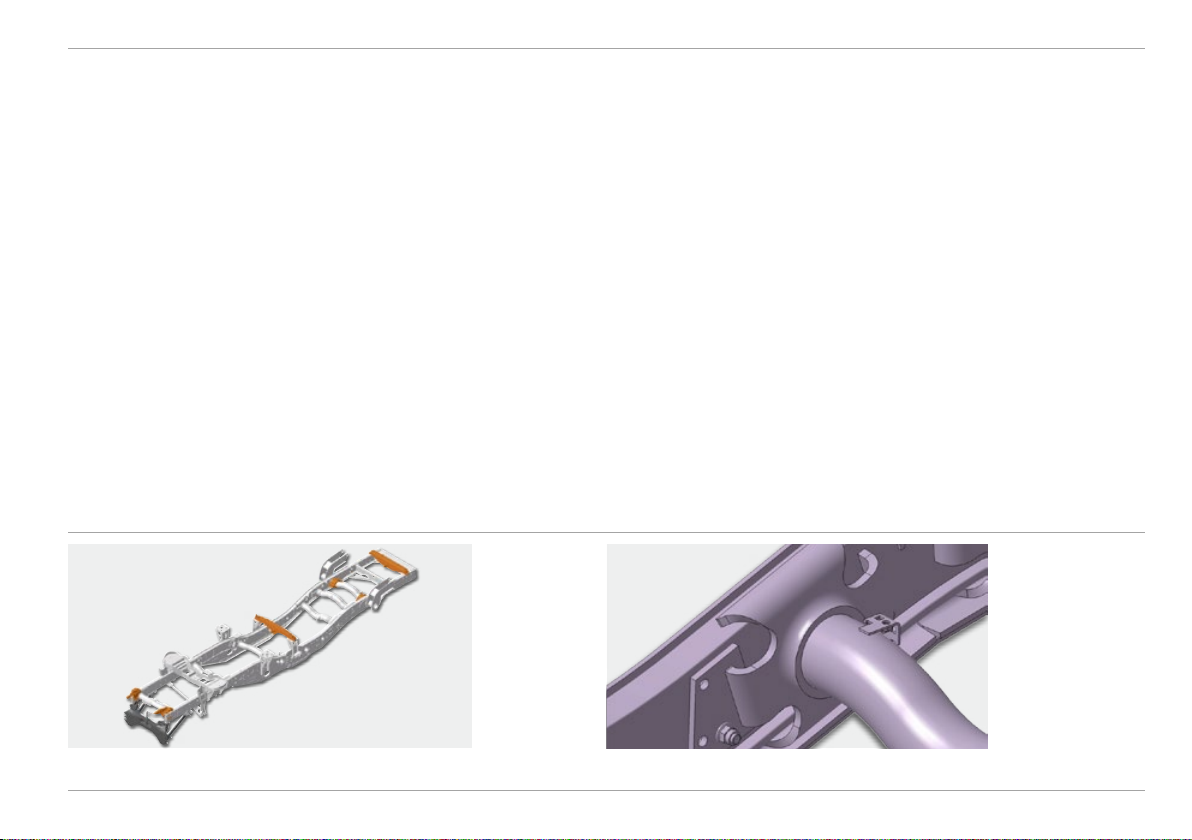
Feature
• 2 U-section longitudinal frame members with welded tubular
cross-members and reinforcements in the frame profile
• Offset design, no components protruding downwards
• Robust steel bumper
• Special torsionally flexible connection flange
Advantage
• Heavy-duty, flexible and torsionally flexible frame offering
high elasticity
• No permanent deformation even after extreme diagonal torsion
• Enables all four wheels to remain permanently in contact with the
ground in all driving situations
• Safe and controlled off-road driving
• Installation of drive units at lowest possible point:
low centre of gravity, high ground clearance
• Protection of components in off-road terrain
• Robust protection from mechanical influences in collisions
• Transmission of high torsional forces between longitudinal and
transverse members
Frame with attachment fixtures for non-MB bodies [CD5], front mounting
brackets [CA2], front mounting plate [CP3], cable winch brackets (CH5)
Mercedes-Benz Special Trucks
Special torsionally flexible connection flange
13
Frame Technical Manual
Feature
• Integrated attachment points
• 3-point mounting of cab, engine and gearbox
• Double 3-point mounting for bodies and attached equipment
Advantage
• Suitable for attaching heavy front- and rear-mounted implements
with defined transmission of forces
• Torsion and stress-free mounting of components and bodies
• No restriction of off-road capabilities
• Equipment, attachments and bodies can be mounted in the ideal
positions with regard to torsion and centre of gravity
• Transmission of trust, tensile and weight forces to the intended
points in the frame
• Safe, secure and simple attachment and mounting of equipment
Even with extreme
axle articulation (30°)
there is only a limited
amount of twist
between cab and
body (12°)
3-point mounting of engine and gearbox
14 Mercedes-Benz Special Trucks
Technical Manual
Optional equipment – frame
Frame
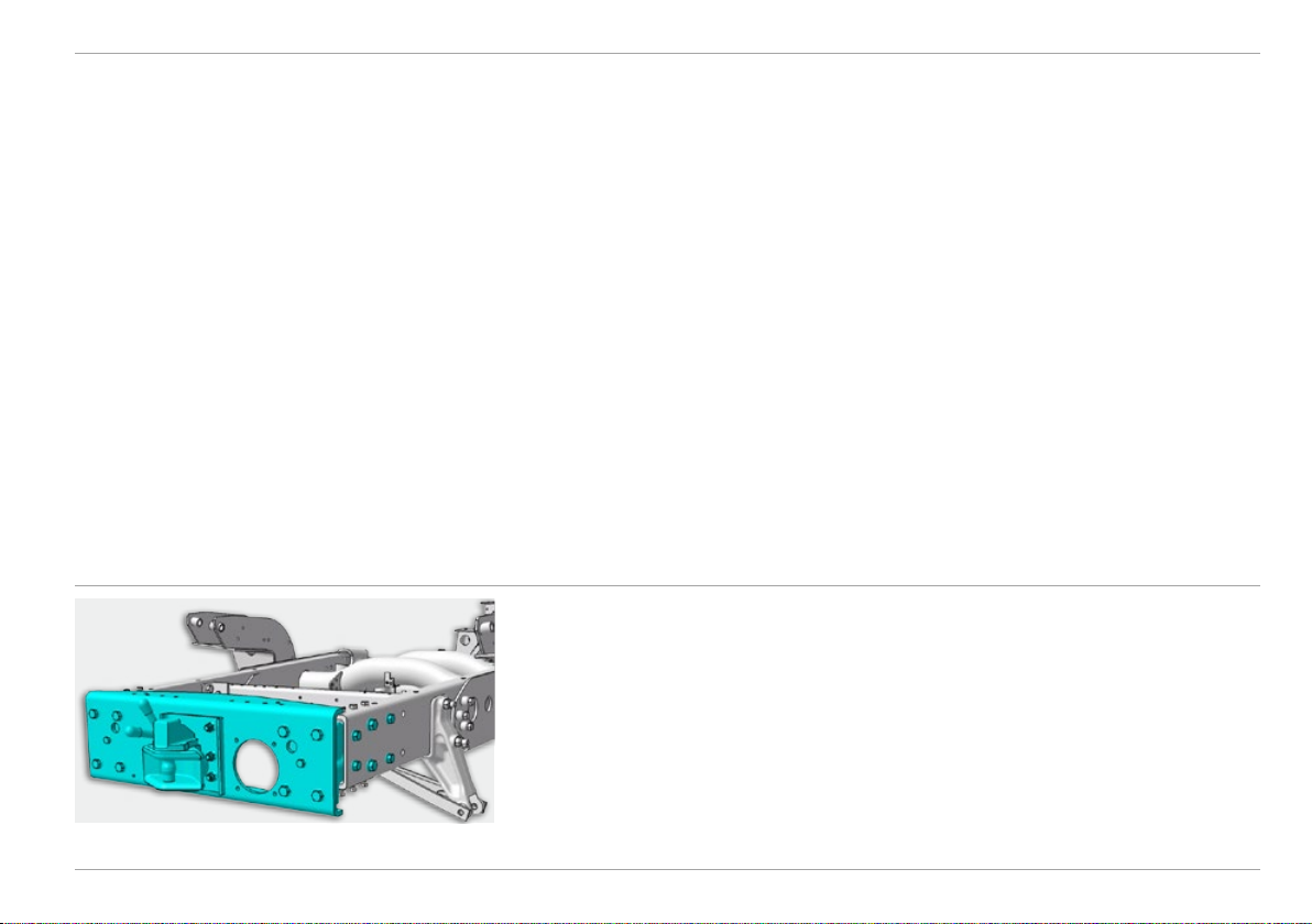
Feature
[Q32] End cross-member, for increased towing capacity
• Reinforced end cross-member
[Q35] Additional towing jaw at front, lowered
• Additional trailer hitch at front
Advantage
• Enables use of draw-bar trailers
up to 15.4 t (U 4023) and 19.9t (U 5023)
• Enables use of rigid draw-bar trailers and centre-axle trailers up to
9 t (U 4023 / U 5023)
• Facilitates manoeuvring
• Towing possible, e.g. with towing bar
End cross-member, for increased towing capacity [Q32]
Mercedes-Benz Special Trucks
15

Frame Technical Manual
Feature
[Q06] Trailer coupling, larger jaw, annual spring, pin 38.5
• Jaw size 280 x 170 mm
• Make, type: Ringfeder 86 G 110
• Drawbar load: 500 kg
• Pin diam.: 38.5 mm
• Swivelling coupling pin
[Q86] Trailer hitch, small jaw, Rockinger, increased load
• Jaw size 200 x 100 mm
• Make, type: Rockinger 225 G 110
• Drawbar load: 700 kg / 1500kg*
• Pin diam.: 38.0 mm
[Q88] Trailer hitch, small jaw, Rockinger
• Jaw size 200 x 100 mm
• Make, type: Rockinger 227 G 110 J
• Drawbar load: 500 kg / 1250 kg*
• Pin diam.: 38.5 mm
[Q97] Trailer hitch, large jaw, Rockinger
• Jaw size 360 x 215 mm
• Make, type: Rockinger 4040 G 135, version A
• Drawbar load: 700 kg / 1000 kg*
• Bolt Ø: 38.5 mm for 40-mm eyelets
• Swivelling coupling pin
* Only in conjunction with [Q32].
Advantage
• For trailer operation with 40 mm towing lug
• For trailer operation with 40 mm towing lug
• High trailer loads possible
• For trailer operation with 40 mm towing lug
• Minimal installation space required
• For trailer operation with 40 mm towing lug
• One-hand operation optimised
• Optimisation of locking and bearing points on coupling body
• 30 – 40 % longer lifespan
16
Mercedes-Benz Special Trucks

Technical Manual
Engine
Engine concept
Engine
Feature
• Newly developed Mercedes-Benz 4-cylinder OM934 engine
rated at 170 kW/231hp and 5.1 l displacement
• Common rail direct injection with high injection pressures
(up to 2400 bar)
• Multistage injection
• Twin-stage turbocharger
• Mercedes-Benz BlueTec 6 technology, Euro VI compliant:
combined SCR technology with particulate filter and cooled exhaust
gas recirculation (EGR)
Advantage
• Proven engines of the Mercedes-Benz volume series
• High power reserves
• Efficient and clean combustion
• Optimised fuel consumption
• Smooth running
• High torque even at low engine speeds
• Reduced NO
emissions
x
• Reduced particulate emissions
OM934 4-cylinder engine
Mercedes-Benz Special Trucks
17
Engine Technical Manual
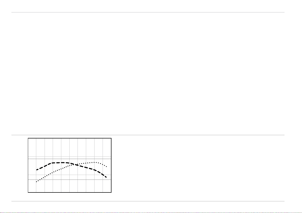
Feature
• Optimised choice of materials and manufacturing process
• Extended maintenance intervals – 1400 operating hours
• High torque, max. 900 Nm
• Optimised in-engine combustion
• Air intake on right of cab at roof level
1500 300
1000
500
170 kW900 Nm
200
100
Output and torque
diagram for
OM934, 170 kW,
900 Nm
Advantage
• Service life extended by 20 %
• Extended use period, low service requirements, reduced
operating costs
• High pulling power and holding ability of torque
• High adaptability on very rough off-road terrain with steep gradients
®
• Significantly reduced AdBlue
consumption
• Intake of combustion air from area with low dust content
• No entry of water into the intake during fording
• Reduced soiling and extended service life for the air filter
Torque [Nm]
200 0
600 1000 1400 1800 2200
Engine speed (rpm)
18 Mercedes-Benz Special Trucks
2600
Engine power [kW]
Technical Manual
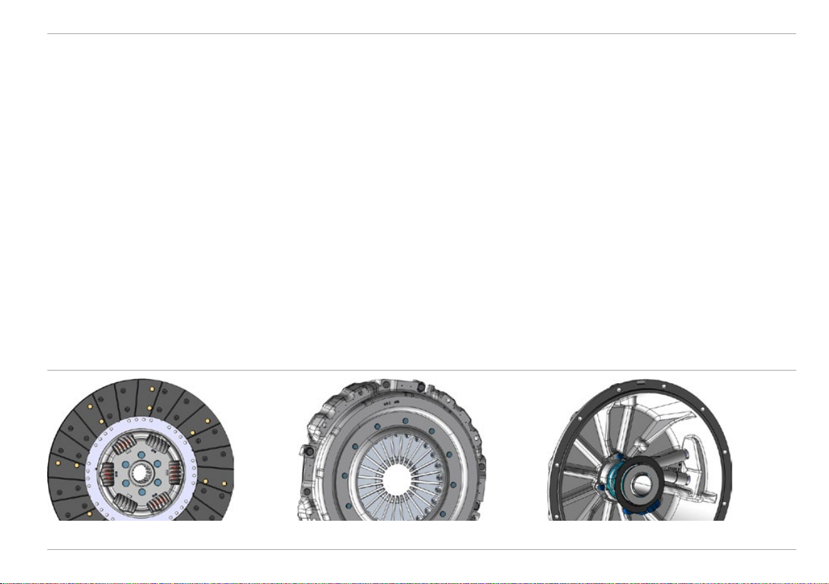
Drive clutch
Engine
Feature
• 395mm single-plate dry clutch
• Hydraulic central clutch release bearing
• Pneumatic clutch pressure booster
• Position sensor
• Wear compensation
• Aluminium clutch housing
• Organic, asbestos-free clutch linings
Advantage
• Easy to regulate, long service life
• No lubrication of moving parts necessary
• Low pedal force (approx. 150 N)
• Wear detectable without disassembly
• Secure frictional connection
• Weight optimisation
• Environmentally compatible
Clutch plate Clutch pressure plate Clutch housing
Mercedes-Benz Special Trucks
19
Engine Technical Manual
High-performance engine brake
Feature
• 2-stage decompression brake
• Control via exhaust camshaft
• Power output up to 178 kW
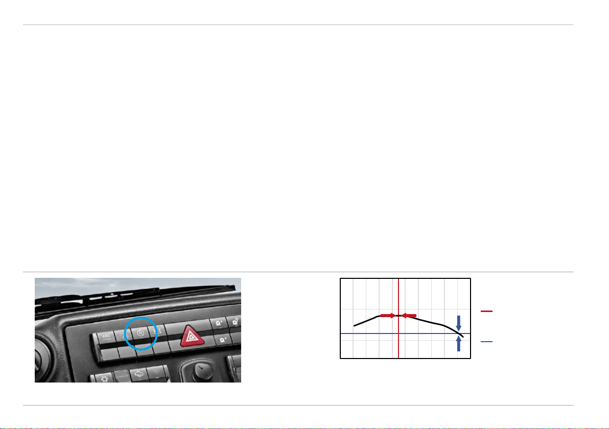
Engine control
Feature
• 2 selectable engine control characteristics
— Torque control (elastic rpm characteristics)
— Work speed control (rigid rpm characteristics)
Switch to select engine control characteristic on dashboard (middle)
Advantage
• Wear-free auxiliary brake, reduces heating and wear of the
service brake
• High brake power, very good deceleration
Advantage
• Rpm characteristics optimally tailored to the operating mode
— Operation under normal conditions, road travel, transport
— Implement use at constant engine speed
— Operation on difficult terrain with speed setpoint, only minimum
engine speed deviation
1500
1000
Torque [Nm]
500
600 1200 1800 2600
Engine speed/torque control
Engine speed (rpm)
Torque and work speed
control:
Engine speed control
for implement operation
Torque control for
driving mode
20 Mercedes-Benz Special Trucks
Technical Manual
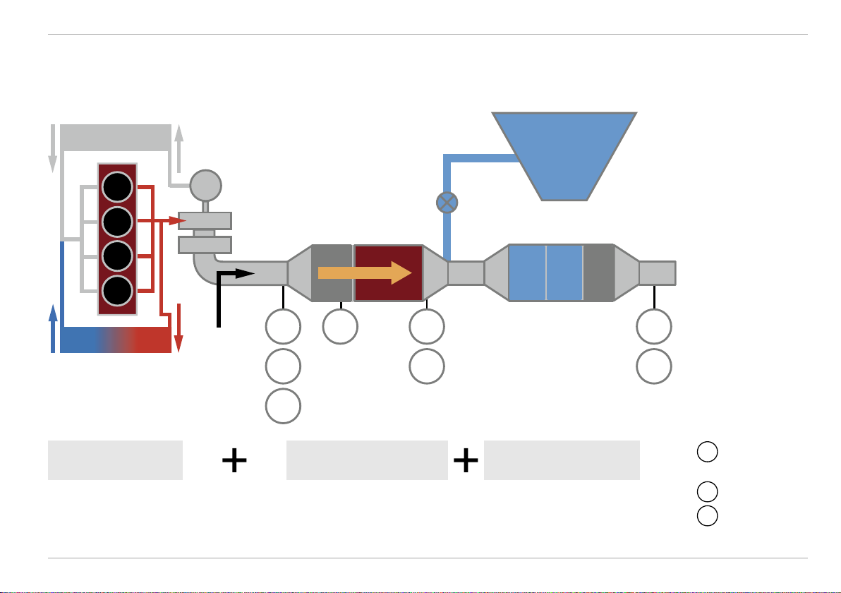
Exhaust gas aftertreatment – BlueTec 6
Intercooler
Engine
AdBlue® tank
EGR cooling
Exhaust gas
recirculation (EGR)
Mercedes-Benz Special Trucks
V
TT
Fuel injection
®
AdBlue
metering
Exhaust
P T T T
NO
X
P
P
Diesel particulate filter
(DPF)
Selective Catalytic
Reduction (SCR)
NO
X
P
Pressure
sensor
NO
NOX sensor
X
T
Temperature
sensor
21
Engine Technical Manual
Feature
• Newly developed Mercedes-Benz engines and exhaust box with
®
BlueTec
diesel technology
• Exhaust gas recirculation
• Diesel particulate filter
• SCR catalytic converter
®
• Optimised AdBlue
injection
• Regeneration of diesel particulate filter during operation
• Downward-facing tailpipe as standard, upward tailpipe available
as option [K7A]
1
SCR catalytic converter
2
AdBlue® tank
3
2
1
3
AdBlue® metering unit
Advantage
• Euro VI compliance
• Proven technology of the Mercedes-Benz volume series, optimised
design to minimise space requirements
• Low NO
emissions
x
• Particulate matter in exhaust flow reduced by 90 %
• Converts NO
conjunction with AdBlue
into harmless nitrogen and water vapour in
X
®
• Reduced AdBlue® consumption
• Longer filter replacement intervals and long filter service life
• Equipment customisable to intended application of vehicle
AdBlue® components
22 Mercedes-Benz Special Trucks
Reduced environmental impact with BlueTec 6, e.g. in
conservation areas

Technical Manual
Exhaust emissions – limiting values
CO: HC: NOX: PM:
Engine
1.5
0.46
Emissions [g/kWh]
Emissions [g/kWh]
0.13
Euro V Euro VI
Euro V Euro VI Euro V Euro VI Euro V Euro VI
i
Standard Vehicle category Legal requirement since/from
Euro V Trucks > 3.5 t 01.10.2009
Euro VI Trucks > 3.5 t 01.01.2014
Mercedes-Benz Special Trucks
2.0 0.021.5
Emissions [g/kWh]
Emissions [g/kWh]
0.01
0.4
23

Engine Technical Manual
Regeneration
Soot from diesel combustion continuously accumulates in the closed
diesel particulate filter. To guarantee longer filter change intervals and
a long filter service life, regular regeneration of the diesel particulate
filter is necessary.
High exhaust temperatures effectively reduce the soot. As the exhaust
gas temperatures are not always sufficient to produce continual soot
reduction (passive regeneration), there is an automatic triggering of
active regeneration, which is dependent on the operational profile
of the vehicle. If necessary, the driver will be requested to initiate the
regeneration manually when the vehicle is stationary. To do this the
idling speed is increased to approx. 1400 rpm in order to achieve
the optimum exhaust gas temperature.
Passive regeneration
• Continuous, at exhaust gas temperatures > 250°C
• No additional diesel injection into exhaust flow
• Takes place during driving without the driver noticing
Active regeneration
• Takes place subject to conditions of vehicle operation
• Triggered automatically with notification in instrument cluster,
no action required from driver
• Additional diesel injection to increase the exhaust temperature
• Can be suppressed by means of theInhibit switch in dangerous
situations or special operations
• Regeneration can be effected manually with vehicle at a standstill
when notification appears in instrument cluster
The percentage of passive or active regeneration is dependent on the
engine load and the vehicle’s usage profile.
1
2
1
DPF regeneration
switch
24 Mercedes-Benz Special Trucks
Inhibit function (block/allow regeneration)
2
Initiate regeneration manually
Special operations/emergencies
The Inhibit function serves solely to suppress the regeneration process briefly in exceptional situations and must
be reset manually after use. Permanent use of the Inhibit
function will lead to premature filter loading which cannot
be reduced. Unscheduled replacement of the filter will
then be necessary.
Information field
“Regeneration
deactivated”
Information field
“Regeneration
overdue”
i
Information fields on the display show
when the Inhibit switch is active and
indicate when regeneration is overdue.
Technical Manual
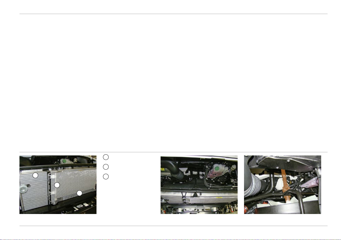
Radiator system
Engine
Feature
• Separate charge air and water cooler (arranged next to one another)
• One fan for both coolers with electronic viscous coupling, mechanically driven via propeller shaft
• High ground clearance of approx. 1100 mm with 365/85 R20 tyres
• Installation location above frame protected by solid underride guard
• All radiators designed for dirt-intensive applications
• Easily removable cover on front of vehicle
1
Charge air cooler
2
Radiator
1
3
2
3
Air conditioning
condenser
Advantage
• Improved cooling capacity
• Reduced risk of soiling
• Easier cleaning
• Safety during fording
• Enhanced cooler efficiency ► fuel savings
• Protection from external factors (stones, branches, mud, etc.)
• Maximum functional reliability maintained even when driving
through water
• Protection from mechanical influences
• Long cleaning intervals
• Excellent accessibility for cleaning
Separate cooler assemblies Coolers for charge air and engine cooling
water arranged next to one another
Mercedes-Benz Special Trucks
Fan with electronic viscous clutch,
mechanically driven via propeller shaft
25

Engine Technical Manual
Optional equipment – engine
Feature
[M55] Fuel preheating, with water separator
• The container consists of a prefilter with heated water
separator. It removes coarse impurities and water fractions
from the fuel upstream of the standard filter.
• Auxiliary heating system to preheat the fuel
• Water storage tank (0.5 l)
[Z0A] Cold climate package
[K7A] Exhaust system, tailpipe vertical
• Exhaust pipe extending up to cab roof on right-hand side of
vehicle
• Stainless steel heat guard
Advantage
• Even low-grade fuel is supplied to the engine free of particulate
matter and water. Avoidance of damage to the injection pumps as a
result of increased water content and dirt
• High operational reliability despite poor fuel quality, unscheduled
maintenance and service costs are avoided
• Enhanced operational reliability at low temperatures, as the
risk of gelling as a result of paraffin separation is reduced
• Problem-free engine start at extremely low outside temperatures
down as low as -26 °C
• Exhaust gases are discharged upwards:
— advantageous during stationary operations (e.g. crane operation)
— no hot exhaust gases close to the ground
• Also prevents corrosion, resulting in longer value retention
26
Mercedes-Benz Special Trucks
Technical Manual
Transmission
Main transmission
Transmission
Feature
• Fully synchronised manual gearbox with eight forward and
six reverse gears
• Helically geared
• Integrated transfer case with torque ball connection
• Reverse gears are ⅓ slower than forward gears
• Synchronised reversing group (EQR) for direct changeover
between forward and reverse gears
• Discrete design
• Low mounting
• Double cone synchronisation
• Optionally extendable by eight off-road gears [G22]
Advantage
• Appropriate forward and reverse speeds for on- and off-road use,
simple and swift gear-changing
• Very smooth running, long service life, high efficiency
• Enables extreme axle articulation
• More effective gear spacing for manoeuvring
• Fast turning, rocking free
• Minimal transmission of engine vibrations
• Torsional flexibility
• Low vehicle centre of gravity
• Long service life
• Short shift times
• Ideal gear-step ratio for any application profile
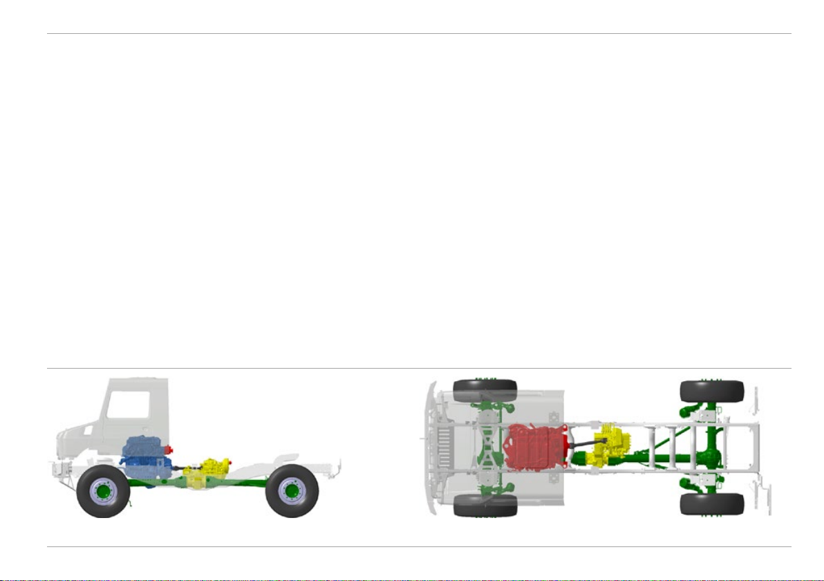
Modular design of engine and gearbox (side view) Modular design of engine and gearbox (from above)
Mercedes-Benz Special Trucks
27
Transmission Technical Manual
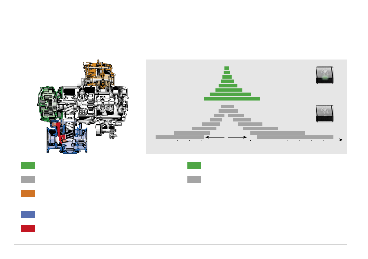
Overview
Fully synchronised Daimler 8-speed EPS manual transmission
Reverse Forward
60 50 40 30 20 10 0 10 20 30 40 50 60 70 80 90
V [km/h]
Range group with off-road range [G22]
Main gearbox
Off-road gears [G22]: approx. 2.1 km/h – 27.1 km/h
Basic gears: approx. 6.6 km/h – 90 km/h
Synchronised Electronic Quick Reverse gearshift
(EQR gearshift)
Transfer case
Engagement of front-axle drive via dog clutch
28
Mercedes-Benz Special Trucks
Technical Manual
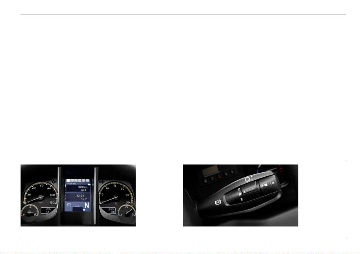
Engine management
Transmission
Feature
• Operation via multifunction lever
• Automatic determination of the correct subsequent gear, indication
on display
• Depress clutch for gear change, changeover occurs automatically
• No mechanical/hydraulic connection between selector lever and
gearbox
• Minimal physical effort required of driver, shifting work performed
by pneumatic cylinder
• Neutral switch with detent position in multifunction lever
Advantage
• Convenient arrangement of shift elements and controls
• Optimal gear pre-selection
• Protection of engine, clutch and transmission
• During gear changes the right hand is free (e.g. for operating
implements)
• No transmission of vibrations to cab
• Allows drivers to relax and concentrate on driving
• Direct shifting to neutral from any gear
• Automatic gear selection from neutral, at any speed
Gear selection indicator in instrument cluster Multifunction lever
Mercedes-Benz Special Trucks
29

Transmission Technical Manual
Electronic Quick Reverse (EQR)
Feature
• Direct changeover between the forward and reverse gears in all
working gears and up to 3rd gear of the road range
• Pre-selection of forward/reverse gears on multifunction lever,
confirmation via clutch
Advantage
• Reliable and fast changeover, high adaptability through rapid
changes between gears
• Changeover to reverse gears possible from all forward gears
• Highly reliable shifting
• Reduced driver workload, better handling, better response during
turning, e.g. when rocking free in off-road terrain
EQR gearshift on multifunction lever EQR gearshift enables rocking free on off-road terrain
30 Mercedes-Benz Special Trucks

Technical Manual
Optional equipment – transmission
Transmission
Feature
[G48] Automatic Shift (EAS*)
• Automatic gearshifts
• Automatic clutch operation
• Automatic torque control during clutching
• Manual gear-change selectable
• Manual clutch operation with clutch pedal folded out
• Remote clutch control integrated [G5F]
* EAS: Electronic Automated Gearshift
i
A = Automatic gear change
Automatic shifting according to load condition, accelerator
pedal position, engine mode, uphill/downhill gradient and
engine brake.
M = Manual gear change
Manual gear selection on the multifunction lever. The driver
determines the gear, clutch operation occurs automatically.
Selected gear is maintained when driving uphill or downhill.
Advantage
• Relieves driver workload in all shift-intensive applications
• Full concentration on traffic
• 2-pedal system
• Reduced clutch wear
• Driver selects optimal gear in implement operation or off-road
• Sensitive control in difficult driving situations
• Drivetrain remains closed in extreme situations, even at idling
speed
• External control of the clutch possible, e.g. for switching in power
take-off
i
In difficult driving situations, such
as are encountered in extreme
off-road use and work operations,
the clutch pedal can be folded out
to enable sensitive control. When
folded in, driving with automatic
Folding clutch pedal
clutch operation considerably
facilitates work.
Mercedes-Benz Special Trucks
31

Transmission Technical Manual
Feature
[G22] Range group with off-road range
• Additional range with eight forward and reverse gears
downline of the main gearbox
• Reduced gear-ratio step, approx. 2.2 to 27 km/h
• Step-down ratio relative to road range i = 3.19
[G28] Preparation for working / off-road gear range
• Technical modifications to the main gearbox to prepare for
retrofitting of the off-road gear range [G22]
[G50] Gearbox oil cooler
• Mandatory:
— operation in hot countries
— use of mineral oils
— for non-civilian use
— in case of continuous power take-off > 50 kW
[G5F] Clutch, remote-controlled
• Clutch remote control for power take-off in conjunction
with [E87]
Advantage
• For low operating speed
• For increased tractive power with narrowly defined speed steps
• Improved manoeuvrability in extreme off-road terrain
• Allows cost-effective retrofitting at a qualified workshop
• Delivers the necessary cooling capacity even in extreme conditions
• Controlling and switching the power take-off on and off are also
possible from outside the cab, e.g. for operating the pump on fire
engines
32
Mercedes-Benz Special Trucks
Technical Manual
Axles
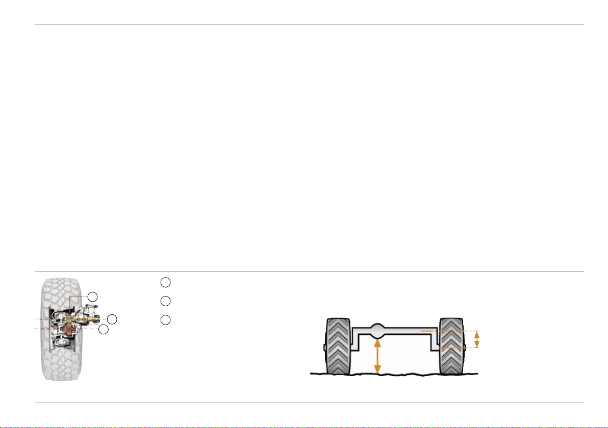
Portal axles
Axles
Feature
• Axles in portal configuration, connected via torque tubes to the
gearbox, eccentric differential
• Axle tube and differential lie above the wheel centre
• Gear ratio step in hub reduction gear
• Uniform speed of front and rear axle in all-wheel-drive mode
• High front axle load in relation to gross weight
• Reinforced axles
1
Hub reduction gear
1
3
2
2
Wheel centre
3
Axle centre
Advantage
• Extreme ground clearance in conjunction with a low centre of gravity
• Enables safe driving over obstacles
• Vehicle can be driven through deep wheel tracks without
becoming stuck
• Sleek drivetrain, smaller axle housing
• Increased traction in off-road terrain
• High payload, attachment of heavy front-mounted implements
• Maximum utilisation of the vehicle by means of duly configured
implement combinations
• Higher axle loads
Portal axle with hub reduction gear
Mercedes-Benz Special Trucks
33

Axles Technical Manual
1
Cross strut
2
Stabiliser
3
Torque tube
4
Spring-loaded
5
parking brake
5
Axle strut
3
4
3
1
2
Front and rear axle U 5023 in portal configuration with cross strut and stabilisers
34
Mercedes-Benz Special Trucks

Technical Manual
Axle suspension
Feature
• Torque tube with cross strut
• Coil springs with progressive compliance characteristic and wide
distance between spring centres
• Shock absorbers on all four wheels
• Stabilisers at front and rear
• New stabiliser mounting as molecular bearing
Axles
Advantage
• Axle location in transverse and longitudinal direction
• Offers high degrees of freedom
• Long spring travel and extensive axle articulation
• Enable shorter frame overhangs (at front and rear) in comparison to
leaf springs
• Higher angle of approach/departure and short front end
• Permanent ground contact possible for all four wheels, even on
extremely uneven surfaces
• High driving stability and ideal suspension set-up for every load condition
• High driving stability, reduced roll tendency
• Firm grip for all wheels in all speed ranges
• No restriction of ground clearance
• Improved cornering stability, reduced roll tendency
• Improved driving safety with attachments which have a high centre
of gravity
• Durable and robust
1
Cross strut
2
Stabiliser
Coil springs with telescopic shock absorbers Rear view
Mercedes-Benz Special Trucks
1
2
35

Axles Technical Manual
Torque tube technology
Feature
• Torsionally flexible fixing/mounting of axles via torque balls on
gear housing
• Propeller shaft is located in the torque tube
• The spring system does not affect propulsion in any way
• No trailing arm required
Advantage
• Enables very long spring travel
• Maximum possible diagonal torsional flexibility for the axles
• Protects the propeller shaft from soiling and damage
• No risk of entanglement from plants
• Improved traction in comparison to leaf springs, no S-shape
deformation
• Tractive power boosted by weight transmission
• Wear- and maintenance-free axle suspension
• Lower kerb weight
Extreme spring travel and extensive axle articulation (up to
30°) as a result of torque tube technology and coil springs
36 Mercedes-Benz Special Trucks
Torque tube protects propeller shaft from soiling
and damage, even in extreme terrain
Diagonal torsional flexibility with torque tube
t echnology

Technical Manual
Drive system
Axles
Feature
• Rear-axle drive
• All-wheel drive engageable while on the move via dog clutch
• Differential locks in both axles with 100 % locking effect via positive
connection (dog clutch units)
• Differential locks engageable and disengageable while on the move
• Operated by rotary switch on the dashboard
1
2
Advantage
• For road use: agile, economical, reduced tyre wear, straightforward
handling
• For off-road use: wear-free as a result of positive connection and
slip-free transmission to front axle
• For extreme terrain: slip-free power transmission to all four wheels,
synchronisation of the four wheels, full power transmission (also
possible via one wheel in extreme cases)
• No interruption of pulling power during shifting
• No need to stop the vehicle
• Convenient engagement
3
4
2
1
3
4
Optimum power transmission to the axles on
varying surfaces
Mercedes-Benz Special Trucks
Drive variants and differential locks: (1) rear-wheel drive; (2) all-wheel drive; (3) all-wheel drive, rear-axle differential
locked; (4) all-wheel drive, front- and rear-axle differential locked
37

Axles Technical Manual
Single tyres
Feature
• Broad spectrum of tyre types, such as MPT and traction tyres with
high-cleat tread
• Large-volume MPT low-pressure tyres (broad tyre pressure range
from 1 to 6 bar)
• Four tyres of identical size and width
• Same track width front and rear
Advantage
• Specific equipment for different operating conditions:
on- and off-road, soft ground, desert, etc.
• Low standing pressure
• High traction
• Reduced track in off-road use
• Good self-cleaning
• Advantageous for all-road use
• Low rolling resistance off-road
• High driving stability
• High traction as a result of genuine four-wheel drive
• Simple fitting of snow chains
• Rear wheels run in the track of the front wheels, avoiding the
power-sapping need to form their own track (genuine four-wheel
drive effect)
• Good track overlap
• High driving stability
Single tyres MPT treads High-cleat tread
38 Mercedes-Benz Special Trucks

Technical Manual
Optional equipment – axles
[A30] Tyre pressure control system
Overview
The tyre pressure control system is an electro-pneumatic system
installed in the vehicle for automatic tyre inflation and deflation at
the front and rear axles while on the move.
1 2 3 4 5
13 12 11 10 9 8 7 6
1
Hose line to the wheel rim
2
Wheel rim:
3
Wheel hub
4
Drive gear
5
Axle tube
6
Compressed air line
7
Shaft seals
8
O-ring
9
Sleeve
10
Fitting
11
Quick-release coupling
12
Test and filling valve
13
Wheel nut cover
Axles
Mercedes-Benz Special Trucks
39

Axles Technical Manual
[A30] Tyre pressure control system
Feature
• Adaptation of the tyre pressure during driving
Advantage
• Adjustment of tyre pressure from the cab while on the move
• Fast and flexible adaptation to road and ground conditions
• Tyre pressure at front and rear axles individually adjustable on
basis of pre-programmed pressure levels
• Equalisation of pressure loss, in case of tyre damage vehicle can
be driven to the nearest workshop
• Adjustment of actual rolling circumferences of front and
rear wheels
• Consideration of different axle loads
• 4-channel system
• Operation via steering wheel buttons and intuitive menu navigation
• Indication of the tyre pressure on the display
Pre-selection of tyre pressure on display,
operation via steering wheel buttons
40 Mercedes-Benz Special Trucks
Push-button switch for tyre pressure
control system
• User-friendly, safe control via pre-programmed tyre pressure levels
• Monitoring of the settings and detection of pressure loss
• Prevention of tyre damage
Left: attachable hose line, test and filling valve for rim and tyre
Right: driving condition, valve and line protected under the wheel hub

Technical Manual
Axles
[A30] Tyre pressure control system
Halving the tyre pressure off-road means doubling the ground contact
area and the tractive force.
High tyre pressure on the road
• Small contact area
• Low tyre wear
• Low fuel consumption
• High load capacity at
high speed
• Good track-holding and
very stable steering
Tractive force [kN]
Traction conditions depending on the tyre pressure
50
40
30
20
10
1.5 2 2.5 3 3.5 4 4.5 5
Tyre pressure [bar]
Low tyre pressure off-road
• Large contact area
• Low ground pressure,
less field damage
• Less slip
• High traction
• Good self-cleaning (tread)
• Minimal ground compaction,
fewer ruts
• No getting stuck
Mercedes-Benz Special Trucks
41

Axles Technical Manual
Feature
[A23] Guard plate for callipers
• Guard plates on the callipers to repel stones, branches,
wires, etc.
[A26] Reinforced wheel stud covers
• Reinforced covers for the wheel studs (wheel hub cover)
[A27] Double sealing of wheel hubs, for operations in muddy
conditions
• Additional sealing rings
[A28] Encapsulation of hub reduction gear, for operations in
extremely muddy conditions
• Complete encapsulation with additional sealing rings
• Mechanical drainage valves in compressed air system
• Only available as standard for U 4023, feasible for U 5023
via CTT code [UA28]
Advantage
• Protect brake callipers from damage in off-road use
• Protection from damage in extreme off-road territory
• Prevents water and fine sand from entering into the hub
reduction gear
• Prevents water and fine sand from entering into the hub reduction
gear and the brakes
• Special protection for operations in extremely muddy and sandy
terrain (e.g. open-pit mining operations)
• Facilitates drainage of the compressed air system
42
Mercedes-Benz Special Trucks

Technical Manual
Brakes
Dual-circuit braking system
Brakes
Feature
• Pneumatic disc brakes at all wheels
Advantage
• Uniform braking effect
• No overheating even under continuous stress
• Maintenance- and repair-friendly
• Automatic load-dependent brake (ALB)
• Brake wear indicator
• High-pressure system (18 bar) via gear-driven heavy-duty
compressor
• Air dryer
• Brake power regulation depending on the load condition
• Timely indication when maintenance is due
• High brake-air pressure
• Less space required for air tank, more space available on the vehicle
• No corrosion
• No freezing of the lines
• Spring-loaded parking brake, acting on the rear wheels
1
3 4
1 2
Design of a sliding-calliper disc brake system Disc brakes on all four wheels offer safety in off-road terrain,
Mercedes-Benz Special Trucks
Diaphragm cylinder
2
Brake calliper
3
Brake carrier
4
Brake disc
• High braking force, minimal braking effort required of driver
even with heavy bodies
43

Brakes Technical Manual
4-channel ABS
Feature
• In case of a locking tendency, the pressure of the wheel cylinder is
corrected according to the road surface condition and load condition
• 4-channel ABS in all model designations
• ABS can be switched to off-road mode
i
Up to 15 km/h: locking
15 – 40 km/h: brief locking
Over 40 km/h: no locking
Advantage
• Safe handling characteristics during braking
• Driving stability and steerability are preserved
• Reduced risk of accidents
• High level of safety through separate actuation of each wheel at
the front and rear axles
• Volume production-tested
• Wheels can lock to a certain extent, in order to build up an
earth wedge
Switch to change ABS mode (off-road)
44 Mercedes-Benz Special Trucks

Technical Manual
Optional equipment – brakes
Brakes
Feature
[B2Z] Parking brake, also on front axle
• Service and parking brakes are electro-pneumatically
coupled as a securing brake.
• The parking brake acts on the rear wheel, in addition
the service brake acts with reduced pressure on the
front wheels
• Only when the engine is running
[B5B] Trailer brake, 2-line
• Pressurised fill line (red)
• Unpressurised brake line (yellow)
• Braking effect from air admission to the brake line
[B5N] Compressed air filling connection, front
• External filling of the compressed air system from an
outside source
• Coupling head (red) on the bumper
• Air supply for service brake, spring-loaded cylinder,
®
gearshift, AdBlue
injection, suspension seat, etc.
[B68] Brake connection, front left
• External operation of another vehicle’s service brake system
or control of the vehicle’s own brake system from another
vehicle
• Coupling head (yellow) on the bumper
Advantage
• High stability possible in cable winch operations without additional
aids such as slope supports
• The full weight pressure of the vehicle is available as a holding
force, with due regard to the given coefficient of adhesion
• EU safety standard
• Accommodation of fast-running trailers
• Allows the brakes and spring-loaded cylinder to be activated so
that one’s own vehicle can continue its journey
• For towing the vehicle in the event of engine failure
• Broken-down vehicles can be moved quickly
• Continuous supply of compressed air from external source (hose
connection), maintaining the vehicle on standby for immediate
deployment (e.g. for fire-fighting operations)
• For towing the vehicle in the event of engine failure
• Control of towed vehicle’s service brake system (actuation of brake
from towing vehicle)
Mercedes-Benz Special Trucks
45
Steering Technical Manual
Steering
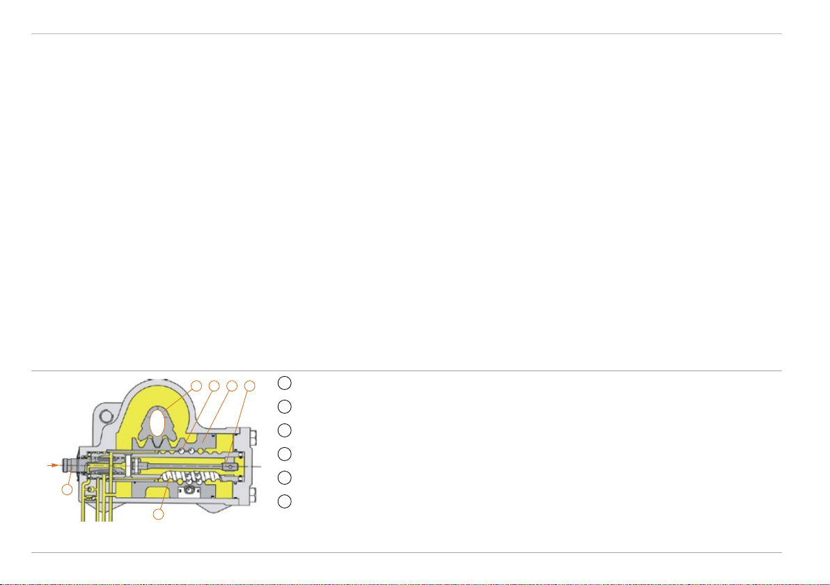
Power steering
Feature
• Hydraulically assisted recirculating-ball steering
• Own power steering fluid supply
• Safety steering wheel with angled steering column
• Steering gear on inside of frame, fluid tank above fording depth
1
3 4 56
to wheel
from steering wheel
1
2
Diagram of the ZF Servocom 8095 steering system
Primary shaft
2
Steering worm
3
Recirculating ball
4
Operating piston
5
Torsion bar
6
Steering shaft
Advantage
• Easy steering even with high front axle loads
• Mechanical part of the steering system remains functional, should
hydraulic power steering fail
• No mixing with hydraulic oil
— Prevents soiling of steering hydraulics
— Fully closed system
• Improved protection in case of collision or accident
• No restriction of approach angle
• Key components in protected area
46 Mercedes-Benz Special Trucks

Technical Manual
Optional equipment – steering
Steering
Feature
[Z01] Vehicle with left-hand drive
• Left-hand control arm
• Steering wheel adjustment
[Z03] Vehicle with right-hand drive
• Right-hand control arm
[Z5Y] Vehicle for right-hand traffic
• Headlamps for right-hand traffic
• Tail lights and rear fog lamps for right-hand traffic
• Mirror for right-hand traffic
[Z5Z] Vehicle for left-hand traffic
• Left-hand traffic headlamps with modified light pattern
• Tail lights with modified positions of the rear fog lamps
• Mirror holders for right and left side of vehicles as prerequisite for modified mirror position
Advantage
• Control of the vehicle on the left side
• Individual adaptation to the driver
• Steering of the vehicle on the right-hand side
• Deployment in countries with right-hand traffic, e.g. Germany
• Deployment in countries with left-hand traffic, e.g. Great Britain
Mercedes-Benz Special Trucks
47

Cab exterior Technical Manual
Cab exterior
Cab concept
Feature
• Engine is located under cab (mid-engine concept)
• Seating positioned behind the front axle
• Minimal frame overhang
• Cab-behind-engine design with short front end
• 3-point cab mounting with rubber elements and shock absorbers
• 120 mm higher and longer than Euro III and Euro V models
• Closed cab roof, optional roof hatch [F21]
+120 mm
+120 mm
Advantage
• Additional distribution of engine weight to rear axle
• Well-balanced vehicle in off-road terrain
• Optimum weight balance due to even loading of front and rear axle
• Seat position in low-vibration area reduces subjection to jolting in
off-road use
• Ergonomic entry
• Large approach and departure angles
• Good visibility to the front in off-road driving
• Reduced exposure to jolts from the road
• Compensation for torsional flexing of the vehicle
• Offers more stowage space behind driver’s and co-driver’s seats
• Great fore/aft seat adjustment range, improved legroom,
greater headroom
1
3
2
1
Front end dimension: 1050 mm
2
Distance steering wheel / front axle: 360 mm
(bottom steering wheel position, max. inclination
towards driver)
3
Position of driver’s seat
Proven cab-behind-engine with greater volume than the
predecessor model
48 Mercedes-Benz Special Trucks
Driver’s seat position behind the front axle, short front end

Technical Manual
Doors
Cab exterior
Feature
• Doors with large opening angle, entry behind front axle, steps and
grab rails
• Exterior mirrors heated and electrically adjustable on both sides
Advantage
• Safe, comfortable and ergonomic entry and exit
• Convenient and safe adjustment from the driver’s seat
Entrance, doors open to a wide angle
Mercedes-Benz Special Trucks
49

Cab exterior Technical Manual
Safety
Feature
• All cabs tested as per ECE-R-29/03 regulation on crash safety
ECE: Regulations of the United Nations Economic
Commission for Europe
ECE-R-29: Protection of cab occupants
Advantage
• High safety standard
• High chance of survival in accidents
i
ECE-R-29 is a voluntary, internationally recognised standard
which confirms the stability of the
survival space for all occupants in
the cabs of commercial vehicles.
Survival spaces for occupants
50 Mercedes-Benz Special Trucks

Technical Manual
Optional equipment – cab exterior
Cab exterior
Feature
[CE3] 3-step entrance
• Full-size third step
• Elastomer mounting, manufactured to EN1846
fire brigade standard
[EM5] Monitor for camera system
• Monitor integrated in the roof lining
• Monitor with four inputs
[EF2] Front camera
• Mounted on front of vehicle, under bumper
[EF3] Rear-view camera
• Mounted on vehicle rear with the aid of a magnetic foot
Advantage
• Comfortable, ergonomic cab access
• Resilient during off-road driving, complies with
fire brigade standard
• In easy view
• Connecting several cameras possible (e.g. front and
reversing camera)
• Full view of the front area, enhanced safety
• Protected location, also for off-road driving
• Full view of the rear area, flexible use
Front camera under bumper Monitor for camera system
Mercedes-Benz Special Trucks
3-step entrance
51

Cab exterior Technical Manual
Feature
[F21] Roof hatch, round, swivelling
• Diameter 75 cm, set clockwise in direction of travel
[F3W] Cab tilting mechanism, mechanical / hydraulic
• Dual action hand pump with lift cylinder
• Automatic, hydraulic-mechanical lock
• Operated behind the front bumper lever on the right-hand
side, by means of lever and socket wrench
• Safety boom
• Only in combination with tilting brackets for cab [F64]
Advantage
• Access to roof attachments from inside the cab
• High flexibility for firefighting and defence operations,
e.g. firefighting from the cab (pump & roll)
• Driving with open roof hatch possible
• Facilitates access to engine compartment for repair operations also
outside workshops
• Safe tilting of the cab
i
Double cab
configurable via
CTT process –
available on
inquiry [UF07].
Cab tilting mechanism [F3W] on front right of vehicle Unimog in forest fire-fighting operation with cab roof hatch,
52 Mercedes-Benz Special Trucks
swivelling [F21]

Technical Manual
Cab exterior
Feature
[F6B] Windscreen, non-tinted, heated
• Heat-insulating windscreen with electric heating for
defrosting
• Operation with rocker switch
[L47] Additional headlamps for front attachments
• Repetition of the main headlights, higher position
[L50] Rotating beacon, yellow, left, with support
• Removable rotating beacon on support
• Support can be extended by approx. 40cm
[L51] Rotating beacons, yellow, left + right, with supports
• Removable rotating beacons on supports
• Supports can both be extended by approx. 40cm
Advantage
• Quick de-icing of the windscreen
• No icing-up of the windscreen while driving
• Windscreen is kept free of fogging
• Windscreen wiper does not ice up
• Compliance with legal provisions for front-mounted implements
• Full illumination, resulting in safer operation of front implements
• High level of passive safety through early identification of vehicle
• Good visibility even with high bodies
• High level of passive safety through early identification of vehicle
• Good visibility even with high bodies
Mercedes-Benz Special Trucks
53

Cab interior Technical Manual
Cab interior
Spaciousness
Feature
• Spacious interior, including stowage space and compartments and
bottle holders
• High cab roof
• Stowage tray, low, on engine tunnel, with cup holder
• 2-seat or 3-seat version available
Advantage
• Great freedom of movement
• Ample stowage space and compartments for personal items,
clothing and equipment
• Orderly and convenient stowage
• Large freedom of movement and headroom
• Frequently required items (shipping documents, mobile phone,
food, etc.) can be kept within the driver’s reach
• Variable seat arrangement, depending on type of application
Spacious interior Multifunction steering wheel
54 Mercedes-Benz Special Trucks

Technical Manual
Controls
Cab interior
Feature
• Control panel in dashboard (centre) with switches arranged
in blocks
• Back-lit controls with adjustable brightness
(when low beam is on)
• 24V power socket
Advantage
• Easy operation through logical switch arrangement
• Clear and ergonomic arrangement within the driver’s reach
• Clearly recognisable in the dark
• New position for parking brake
• High-quality look
• Safe and convenient operation in the dark
• Simple connection of various small appliances in the cab
Controls in the cockpit Inserts in cab roof
Mercedes-Benz Special Trucks
55

Cab interior Technical Manual
Steering and gear-changing
Feature
• Multifunction steering wheel, adjustable for height and tilt
• Multifunction lever
Advantage
• Many functions can be conveniently controlled on the
steering wheel
• Ergonomic seated position, non-tiring driving
• Individual adaptation of the workplace
• Integrated functions such as gearshift, premium engine brake,
Electronic Automatic Shift (EAS), quick reverse gearshift (EQR)
Multifunction lever and multifunction keys on the steering wheel
56 Mercedes-Benz Special Trucks
Adjustment range of the steering column

Technical Manual
Instrumentation
Cab interior
Feature
• Instrument cluster with graphics-capable 10.4 cm TFT display
• Ergonomic arrangement within the driver’s field of vision
• Bright, monochrome display for good, glare-free legibility
• Driver information system – call-up of relevant information such
as oil level, tyre pressure, coolant level, etc.
Advantage
• Swift, comprehensive information on the vehicle’s operating
conditions and status
• Clear, unambiguous presentation of important information
• Avoidance of misinterpretations
• Simplified departure check for the driver via standard start check
without visualisation
Instrument cluster
Mercedes-Benz Special Trucks
57

Cab interior Technical Manual
Standard controls
Instrument cluster
Displays information on:
• Overall vehicle
• Engine status
Multifunction steering wheel
Adjustable for height and tilt
Operation of:
• Radio
• Telephone
• Instrument cluster
• CRUISE CONTROL
• driver information system
• electronic manual throttle
Control panel in dashboard
Multifunction lever
Operation of:
• gear selection (forward/
reverse)
• Gear selection (up/down)
• mode selection (automatic /
manual)
• Engine brake
Operation of:
• all-wheel drive and differential locks
• heating and ventilation system
• Activation and deactivation of additional optional functions
(e.g. operation of tyre pressure control system)
58
Mercedes-Benz Special Trucks

Technical Manual
Air conditioning, heating and ventilation system
Cab interior
Feature
• Combined heating and ventilation system
• Four-speed blower
• Hot water heater with residual heat utilisation
• Pollen filter with coarse dirt grill
• Control unit on control panel (centre)
Advantage
• Individual control of the interior climate
• Fast de-icing of windows
• Fuel savings and environmental protection
• Suitable for dust- and dirt-intensive applications
• Clean and pure air in the passenger compartment, health protection
for driver and co-driver
• Readily accessible, simple cleaning
• Within driver’s reach
Control unit for air conditioning, heating and ventilation system Air flow directions (orange = air intake in recirculation mode)
Mercedes-Benz Special Trucks
59

Cab interior Technical Manual
Optional equipment – cab interior
Feature
[DF1] Suspension seat, air-sprung, driver
• Fitted backrest and integrated head restraint
• Integrated 3-point automatic seat belt
• Air-sprung suspension system, adjustable dampers
• Weight adjustment from 50 to 150 kg,
cycle stroke +/–40 mm, bellows
• 230 mm fore/aft adjustment, in increments of 10 mm
• 100 mm height adjustment, pneumatic assist
• Inclination adjustment 16°, (from –5° to +11°),
finely incremented
• Backrest adjustment in 2° steps (from –12° to +40°)
• Backrest folds down onto seat cushion
[DF3] Suspension seat, air sprung, with seat heating, driver,
corresponding to [DF1], plus:
• 24V seat heater
• 2-chamber lumbar support, armrest tilt-adjustable
[DB1] Suspension seat, air-sprung, co-driver
• Corresponding to [DF1]
[DB3] Suspension seat, air-sprung, with seat heating, co-driver
• Corresponding to [DF3]
[D3Z] Seat cover, imitation leather
• Highly durable, grime-resistant, washable imitation leather
• For driver’s and co-driver’s seat, not for middle seat [D17]
Advantage
• Good adaptation to the contour of the back
• Easily and quickly adjustable to individual heights and weights
• Good damping even on rough roads
• Improved seat climate resulting from fluted upholstery
• Fatigue-free driving
• Good access to stowage space
• Facilitates getting in and out
• Pleasant warmth in cold weather
• Preservation of healthy spinal column, back and kidney area
• Long-lasting quality and upmarket feel
• Easier to clean seats quickly, very good resilience to wear and
tear from getting in and out
60
Mercedes-Benz Special Trucks

Technical Manual
Cab interior
Feature
[D1Z] Centre seat, with seat belt
• Individual seat with head restraint and 3-point automatic
seat belt, in addition to co-driver’s seat
• Rigid seat without adjustment options for backrest and
seat cushion
[DV3] High stowage box with folding table
• Addition to the stowage facilities in the cab
[D6F] Air conditioning system
• Heating and ventilation system is complemented by
an effective integrated air conditioning system for the
single cab
• Air conditioning condenser (cooling output 4 kW) integrated
in engine compartment, bonnet with two air ducts on lefthand side
• Large air outlets on dashboard
• Temperature and blower adjustment in combination
with heating and ventilation system in the middle of the
dashboard
• 3-position rotary switch with pictogram
• Air distribution into the footwell and to the windscreen
• Swivelling nozzles
Advantage
• Comfortable sitting, even on longer journeys
• Space for two accompanying persons (e.g. for transport to and
from the place of work)
• High safety standard for both passengers
• Swift access to important and frequently required items (documents,
tools, mobile phone, food, etc.) within the driver’s reach
• Enhanced comfort and well-being thanks to reduced relative
humidity and pleasant temperature
• Driver fitness is maintained by reduction in the inside temperature
on hot days
• The air is dried during operation in heating mode and this prevents
the windows from misting up
Mercedes-Benz Special Trucks
61

Cab interior Technical Manual
Feature
[D6N] Auxiliary heater with engine preheating over diesel tank
• Auxiliary heater for heating the engine coolant and the cab,
from WEBASTO
• The time for starting heating can be pre-set at up to 7 days
• Three switch-on times can be programmed
• Pre-selection of the temperature
• Operating cycle 10 to 120 min
• Remaining time 1 to 120 min
• Can be switched on while driving
• The heat output is 1.8 to 7.6 kW
• Fuel consumption between 0.2 and 0.9 l/h
• Automatic altitude compensation
[DE4] Power windows, on both sides, with door trim
• Power windows on both doors
• Door trim
Advantage
• Preheated cab and clear view at departure
• Preheated engine, problem-free and gentle start-up of the engine,
even at extremely low outside temperatures
• Increased heat output in the cab
• Warm engine directly from engine start, fuel savings
• Easy engine start, reduced battery wear
• Convenient opening and closing of the windows on both sides
• Enhanced appearance and feeling of comfort
62
Mercedes-Benz Special Trucks

Technical Manual
Cab interior
Feature
[J2A] CD radio
• DIN installation
• CD drive (MP3)
• Mini-USB jack
• 2 x 20 W power output
• 6 station buttons
• 6 x 6 station presets
• AUX jack
• FM-RDS tuner (VHF), AM tuner (MW/LW/SW)
• RDS-EON
• External muting
• Diverse control options (e.g. multifunction steering wheel)
• Large, clearly defined buttons
• Factory installed
®
[J2B] CD radio with Bluetooth
®
• Bluetooth
hands-free unit
corresponding to [J2A], plus:
• Integrated microphone on the front (MIC)
[J1C] Instrument cluster 12.7 cm, with video function
• 12.7 centimetre colour display
• Video input
Advantage
• Highly user-friendly
• High functionality, reception and sound quality
• No malfunctions due to incorrect wiring
• Antenna and speakers included in the scope of delivery
• Fine finish, ergonomic and tailored to interior appointments
• Time-saving and cost-reducing installation at the factory
®
• Mobile phone can be used while on the move via Bluetooth
(recognised hands-free system)
• Radio loudspeakers ensure excellent intelligibility (volume control)
• Good, glare-free legibility with additional information avoids
misinterpretations
• An additional camera can be fitted for enhanced work safety and
optimised comfort
Mercedes-Benz Special Trucks
63

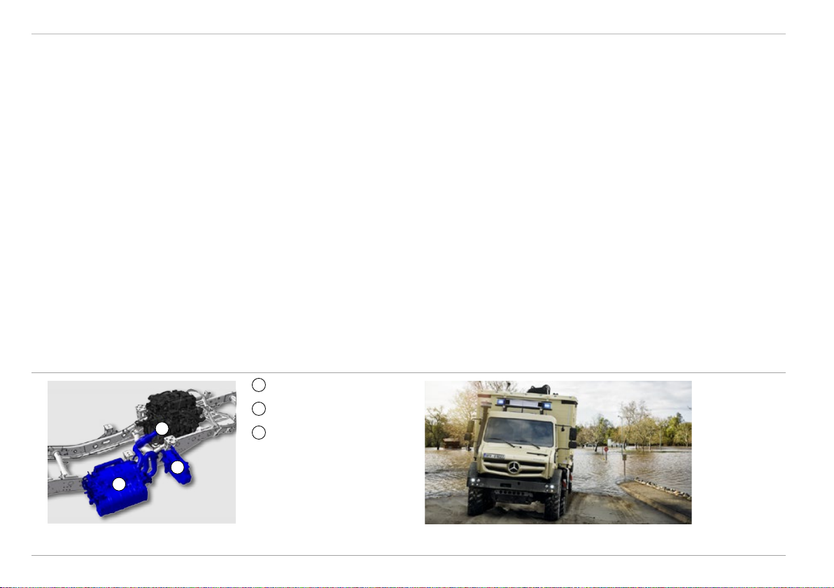
Auxiliary drives Technical Manual
Auxiliary drives
Location
1
2
1
[N05] Engine PTO to rear (with 6-hole flange)
2
[N13] Gearbox PTO, high-speed, with 6-hole flange
[N16] Gearbox PTO, high-speed, with 4-hole connection
[N19] Gearbox PTO, very high-speed, with 6-hole flange
64 Mercedes-Benz Special Trucks

Technical Manual
Optional equipment – power take-offs
Auxiliary drives
Feature
[N05 ] Engine PTO to rear, with 6-hole flange
• Alternative to direct drive of body assemblies with high
power requirement
• Gear ratio i = 0.933
• Independent of the manual transmission
• Electro-pneumatically actuated dog clutch unit
• Operation via push button in control panel in centre of
dashboard, with indicator lamp
• Activation when engine is off, deactivation possible at
any time
Advantage
• High output and torque, up to 600Nm
• No power interruption across the full speed range
• Convenient, defined switching on and off
• Can be used independently of the engaged gear or the drive clutch
i
The engine power take-off can be
switched on only with the engine OFF,
to prevent incorrect operation.
Engine PTO switch Engine PTO (highlighted in red)
Mercedes-Benz Special Trucks
65

Auxiliary drives Technical Manual
Feature
[N16] Gearbox PTO, high-speed, with 4-hole connection
• Standardised flange on manual gearbox (DIN 5480, 4-hole
flange, number of teeth: 14)
• Gear ratio i =1
• Rotational direction anticlockwise as seen in direction
of travel
• Electro-pneumatically actuated dog clutch unit
• Operation via push button in control panel in centre of
dashboard, with indicator lamp
• Only activated when drive clutch is operated and vehicle is
stationary
• Remote control of the clutch with Automatic Shift [G48],
signal picked up via implement socket [E87]
• Programming of the maximum rotational speed
[N13] Gearbox PTO, high-speed, with 6-hole flange
• Corresponding to [N16] with 6-hole flange
Advantage
• Use of commercially available hydraulic pumps
• Output speed and rotational direction identical to engine rpm
and rotational direction
• Convenient, defined switching on and off
• Protected against incorrect operation
• For implement operation from outside the vehicle
• No exceeding of the permissible maximum speed
[N16] Gearbox PTO, high-speed,
with 4-hole connection
66 Mercedes-Benz Special Trucks
[N13] Gearbox PTO, high-speed,
with 6-hole flange

Technical Manual
Auxiliary drives
Feature
[N19] Gearbox PTO, very high-speed, with flange
• Standardised flange at the manual transmission in
accordance with ISO 7646
• Gear ratio i =0.61
• Rotational direction clockwise in direction of travel
• Electro-pneumatically actuated dog clutch unit
• Operation via push button in control panel in centre of dashboard, with indicator lamp
• Only activated when drive clutch is operated and vehicle is
stationary
• Remote control of the clutch with Automatic Shift [G48],
signal picked up via implement socket [E87]
• Programming of the maximum rotational speed
[N18] Preparation for gearbox PTO
• Preparation for retrofitting of [N13]/[N16]/[N19]
Advantage
• Use of commercially available drive assemblies, e.g. fire
brigade pumps
• Convenient, defined switching on and off
• Protected against incorrect operation
• For implement operation from outside the vehicle
• No exceeding of the permissible maximum speed
• Allows retrofitting at a qualified workshop
with flange
Mercedes-Benz Special Trucks
Transmission PTO switch[N19] Transmission PTO, very high-speed,
67

Hydraulics Technical Manual
Hydraulics
Overview of hydraulic system
2
V
1
1
Hydraulic connections at front (red = delivery line, yellow = return line)
2
Hydraulic connections at rear (red = delivery line, yellow = return line)
P
Hydraulic pump
T
Tank
F
Filter
V
Control unit / valve
68 Mercedes-Benz Special Trucks
F
T
P

Technical Manual
Optional equipment – hydraulic system
Hydraulics
Feature
[H10] Hydraulic system, with single spool valve
• Single hydraulic system for universal operation with 240 bar
system pressure and 57litre oil delivery rate at 2200 rpm
• Internal-gear fixed displacement pump on engine PTO for
continuous consumers and positioning movements
• Delivery and return line at front (delivery line as plug; return
line as socket, flat sealing connections)
• Oil temperature warning lamp
• Cable boot at cab front and rear wall
Advantage
• Deployment for both continuous consumers and positioning
movements via valves on the equipment
• Pressure level for common attachments such as cable winch, snow
plough, front loader, hydraulic tools, emergency power generator,
compressor, etc.
• Effective driving of oil engines in conjunction with oil cooler on
equipment
• Open hydraulic system: ideal for controlling single or dual action
cylinders in conjunction with valves on the equipment
• Fixture for installation of an implement control desk
• Direct drive of a front-mounted oil engine possible
• Standardised, leak-free connections with no risk of confusion
(no oil leakage during connection or disconnection)
• Protection of the hydraulic system
• Simple connection for implements
Mercedes-Benz Special Trucks
69

Hydraulics Technical Manual
Feature
[H50] Hydr. plug connection, rear oil supply, 2 connections
• Delivery and return line at rear (connections as at front)
Advantage
• Direct drive of an oil engine (spreader) possible
• Connection option for tipping cylinder via additional
control valves
• Snow plough / spreader combination possible via corresponding
valve combinations (flow dividing valve)
Hydraulic system [H10]: Plug connections at front on the left in
direction of travel: delivery line (red) and return line (black)
70 Mercedes-Benz Special Trucks
Plug connections at rear [H50] on the right in direction of travel:
delivery line (red) and return line (black)

Technical Manual
Electrical system
Electronic networking
Electrical system
Feature
• Electronically instead of mechanically controlled systems
• CAN bus: networking of electronic systems in the vehicle
• OBD diagnostic socket
• The assistance and safety systems communicate in the vehicle
via CAN bus
• Central plug connection between cab and frame
Central plug connections in the engine compartment
Central plug connections in the cab
Advantage
• Faster and more precise
• Functions no longer realisable by mechanical means,
e.g. economical engine through use of electronics
• Very fast, bidirectional data exchange between different control
devices in the vehicle
• Input and output of relevant diagnostic data (Star Diagnosis)
• The driver’s workload is reduced in critical driving situations
• The vehicle is better safeguarded from driving faults
• Driving state signals are immediately displayed
• Simple disconnection of the electrical equipment from the cab,
e.g. for diagnosis or repairs
i
All driving states are electronically compiled, analysed
and relayed accordingly to the engine control system.
This enables the most economical gear to be identified
and engaged, for example.
i
Ex factory, the Unimog model series fulfil regulation
72/245/EEC ’Electromagnetic Compatibility’ in the
version 2009/19/EC.
Mercedes-Benz Special Trucks
71

Electrical system Technical Manual
Optional equipment – electrical system
Feature
[E87] Equipment socket, 32-pin
• Electrical interfaces between vehicle and implement
• Power supply for implements up to max. 40 A
• Speed and position signals C3/C4
• Activation/deactivation of PTOs in conjunction with [G48]
• Interface for connecting an external (at implement end)
engine remote control for start/stop, engine speed change
• Actuation of gearbox for crane body or refuse disposal
vehicles (e.g. speed limiter, immobilizer)
• Eight free lines routed into the cab for optional use by the
bodybuilder
• Signals for activated rotating beacon and back-up lamp
• Actuation of three free indicator lamps
Advantage
• Installation of lines via cable set with defined and unique assignments
• Highly reliable operations between vehicle and implement and safe
and reliable operation of the overall system
i
The relevant connector for the [E87] equipment socket is
available via Mercedes-Benz Parts
A 043 545 15 28 – connector housing, HB-K. 16. STS-GR.1.21
A 000 545 21 63 – crimp contact, HE/HA-C-Sti.Ag. 2.5 mm²
A 000 545 22 63 – crimp contact, HE/HA-C-Sti.Ag. 1.5 mm²
A 051 545 60 28 – plug insert, HEE 32 Sti.C
[E87] Implement socket, 32-pin
72 Mercedes-Benz Special Trucks

Technical Manual
Electrical system
Feature
[E16] Parameterisable special module (PSM), 5 V CAN
• Electronic module for direct exchange of information
between the vehicle electronics and the fitted equipment,
attachments, bodies and the trailer
• Communications interfaces between vehicle electronics and
retrofitted systems are clearly defined and standardised
[EG5] Alternator, 28 V/150 A, protected from soiling,
with fording capability
• Boosted output (1400 W increase)
• Dirt-resistant
• Fording capability
[E1M] Alternator, 28 V/150 A
• Boosted output (1400 W increase)
[E1B] Batteries, 2 x 12 V / 170 Ah, low-maintenance
• 2 12 V batteries
• 170 Ah capacity each
Mercedes-Benz Special Trucks
Advantage
• Enables setting of typical functions, such as:
— reduction of top speed
— blocking of reverse gears
— switching PTO on and off
— increasing/reducing engine speed
— resumption of previous engine speed
• High functional reliability of all components since subsequent
connection of external systems occurs with no intervention in the
vehicle electrical system or electronics.
• Extended functions for trailer/implements via second interface
• More efficient working and enhanced user-friendliness for the driver
• Selling point for resale
• Offers power reserves for additional loads
• Longer lifespan and uninterrupted power supply ensured in open-pit
mining or comparable operations
• No damage from exposure to water, high operational reliability even
under water
• Offers power reserves for additional loads
• Good operating reliability after long breaks from driving and when
running high-performance consumers
• Reduced maintenance effort thanks to low-maintenance design
73

Electrical system Technical Manual
Feature
[E37] Continuous current socket, 12 V/15 A
• For 12 V consumers
• 3-pin
• Via voltage converter 24 V/12 V (on-board electrical
system 24 V) in the E box
• Tap up to 15 A
• C3 vehicle speed signal and ground
• In the cab behind the driver’s seat
• Complies with EN 15431
[E45] Front plug-in socket, 24 V, 7-pin
• 7-pin
• 24V
• Supplies power to turn signal, position and licence plate
lamps at the front implement mounting area
[ED6] On-board socket, 24 V/25 A, in cab, with C3 signal
• Electrical power for implements with C3 signal for
speed-dependent control
• 3-pin
• Behind the driver’s seat
• Complies with EN 15431
Advantage
• For consumers such as 12V spreader, agricultural implements
• Power outlet located in immediate vicinity of the cable boot at the
cab rear panel
• Easily accessible, no hindrance of the driver/co-driver by surrounding cables
• Power supply for the lighting equipment of front-mounted implements
• Easily accessible connection
• For consumers such as 24V spreader
• Easily accessible, no hindrance of the driver/co-driver by
surrounding cables
• Location in cab avoids corrosion from exposure to road salt and
external influences
• C3 vehicle speed signal
74
Mercedes-Benz Special Trucks

Technical Manual
Electrical system
Feature
[E33] Battery cutoff switch on battery box
• Manually operated main switch to cut the battery current
• Switch positioned on the side of the battery box
• The switch head (red) is removable: protection from
unintentional switching on or off
• The power supply to the tachograph is maintained
[E79] Battery cutoff switch, electronic
• Two electronic EMERGENCY OFF switches to cut the
battery current
• Integrated undervoltage protection
• The power supply to the tachograph is maintained
[E86] Automatic battery cutoff switch for fire brigade vehicles
• Automatic cutting of battery current after removing the
ignition key and pressing the cutoff switch
• The power supply to the tachograph is maintained
• Two EMERGENCY OFF switches in cab and outside on
battery box
Advantage
• Deliberate disconnection of all power consumers from the battery
• Protection from battery drainage, leakage current, etc.
• Deliberate disconnection of all power consumers from the battery
• Protection from battery drainage, leakage current, etc.
• Deliberate disconnection of all power consumers from the battery
• Protection from battery drainage, leakage current, etc.
• Immediate manual cutting possible
Mercedes-Benz Special Trucks
75

Electrical system Technical Manual
Feature
[EK7] Special parts for hazardous goods
• Equipment for the transport of hazardous goods by road (ADR)
• Model categories available on request
• Battery cutoff switch for controlled cutoff after
approx. 5 min, excluding the tachograph
• EMERGENCY OFF switches inside and outside of the cab
• Corrugated hose sheathing for the cabling
[C7K] Battery support, batteries above each other
• Battery carrier for two 12 V batteries, positioned one above
the other
• Mounting on the left of the frame (viewed in the direction
of travel)
• Suitable for 2 x 12 V / 170 Ah batteries, low-maintenance [E1B]
• Only in combination with manual battery isolater switch at
battery box [E33]
Advantage
• No cost-intensive and time-consuming retrofits
• Approved in accordance with ECE-R 105
• Customer free to choose ADR classification
• Fast and safe disconnection of power supply in case of danger for driver
or fire brigade
• More space for additional attachments on the frame, e.g. for cranes
with side supports
[C7K] Battery support, batteries above
each other
76 Mercedes-Benz Special Trucks

Technical Manual
Attachment and mounting areas
Locations of attachment and mounting areas
2
3
1
Attachment and mounting areas
Attachment and mounting via:
1
Standardised front mounting
plate, size 3 [CP3], e.g. for
6
earth mover, snow plough,
front-mounted sweeper
2
Front mounting brackets [CA2],
e.g. compressor, emergency
power generator
3
Cable winch bracket
[CA2]+[CH5], e.g. front cable
winch
4
Frame mounting brackets, e.g.
5
frame trussing of slope support
5
Attachment fixtures for non-MB
bodies [CD5], e.g. box, platform
4
Mounting brackets for heavy
attachments which can raise
the vehicle [CA9], e.g. crane,
elevating work platform
6
Floor assembly for special
bodies [P61], e.g. box, platform
Mercedes-Benz Special Trucks
77

Attachment and mounting areas Technical Manual
Mounting areas
Feature
• Factory-designed mounting points and mounting areas fine-tuned in
consultation with implement manufacturers
• Mounting area at front using mounting brackets [CA2], cable winch
bracket [CH5] or front mounting plate [CP3]
• Mounting area at top using attachment fixtures [CD5], mounting
brackets [CA9], floor assembly [P61] and [P69]
• Mounting area between the axles
• Mounting area at front
Advantage
• Simultaneous mounting of implements in conjunction with body
• High cost effectiveness
• Simple and standardised mounting devices
• Payload gain from omission of body-mounting connections
• Payload gain through omission of platform and direct mounting by
means of frame mounting brackets
• The Unimog chassis retains its full unobstructed scope of operation
and functional reliability when the body is fitted
• Minimal stress on body
• Long service life for vehicle and equipment
• Low overall centre of gravity, better driving stability
• Fitting of trusses (e.g. slope support, front loader) or side
attachments (cable winch, generator, etc.)
• For mounting equipment on the front of the vehicle
i
Platform and box-type body produced
by qualified bodybuilders in compliance
with the current body / equipment
mounting directives.
Platform with tarpaulin Platform
78 Mercedes-Benz Special Trucks

Technical Manual
Optional equipment – mounting areas
Attachment and mounting areas
Feature
[CA2] Mounting brackets, front
• Specially developed mounting points on front of
vehicle frame
[CA9] Mounting brackets for heavy equipment (crane bodies)
• Mounting brackets for attaching an external supporting frame
• Modified vehicle packaging, to create space for mounts
or supports
[CD5] Attachment fixtures for non-MB bodies
• For direct attachment of non-MB bodies
• For direct mounting of an external floor assembly
[CH5] Cable winch bracket for front cable winches
• Specially developed mounting points for cable winch
operations
• Only possible with mounting brackets [CA2]
Advantage
• For attaching cable winch brackets [CH5] and front-mounted
implements, for example
• High strength, enabling absorption of higher forces
• No negative influences resulting from frame torsion
• Uniform interface between Unimog chassis and heavy add-on
equipment
• Suitable for heavy, permanently mounted equipment such as
crane, elevating work platform, excavator attachment, drills,
winch attachments, etc.
• Double 3-point mounting retains torsional flexibility for the attached
equipment and maintains the overall vehicle’s off-road capabilities
• High driving stability on the road and ideal adjustment off-road
• Attached equipment does not restrict off-road capabilities in
any manner
• Extreme torsion of the frame results in only minimal body stress
• High strength enables transmission of high tractive forces
• Deployment of front cable winches with high tractive forces
(up to 7000 daN)
• No negative influences resulting from frame torsion
Mercedes-Benz Special Trucks
79

Attachment and mounting areas Technical Manual
Feature
[CL2] Anchoring and loading lugs
• Lugs on vehicle (front, middle rear)
[CP3] Front mounting plate, DIN 76060 type B, size 3
• Integrated towing bracket (maximum tractive force 7.5 kN)
• Implements mounted via claws / pockets and secured by
means of swivelling bolts or collar bolts
[P61] Floor assembly for special bodies
• Simple and secure mounting of box-type bodies and fixed
platform bodies on the floor assembly
• Double 3-point mounting of the floor assembly
[P69] Floor assembly for special bodies, extended
• Extension of floor assembly [P61] for bodies up to body
length of 4100 mm
Advantage
• Simple and secure fixing of the vehicle when loading onto train,
ship, aircraft
• High strength resulting from connection of the attached equipment
via mounting plate to the frame
• Equipment can be transported at top speed
• Swift changing / mounting of implements possible to enable other
operations with the carrier vehicle
• Unimog chassis retains its full unobstructed scope of operation and
functional reliability
• No restriction of off-road capabilities
• Minimal stress on body
• Long service life for vehicle and equipment
• Unimog chassis retains its full unobstructed scope of operation and
functional reliability
• Minimal stress on body
• Long service life for vehicle and equipment
80
Mercedes-Benz Special Trucks


Technical Manual
Technical Manual for extreme off-road Unimog BlueTec 6
Part B
Technical data
Mercedes-Benz Special Trucks
83

Contents
Contents – Part B
Technical Manual
Engine .................................................................................. 86
Engine data – OM934 ..................................................... 86
Engine diagram – OM934 ................................................ 87
Filling capacities .............................................................. 88
Engine brake .................................................................... 88
Compressed air generation .............................................. 89
Transmission .......................................................................90
Main transmission ............................................................ 90
Clutch .............................................................................. 90
Vehicle speeds – U 4023 / U 5023 ................................. 91
Vehicle speed conversion factor ......................................92
Axles ....................................................................................93
Suspension ...................................................................... 93
Technical data on axles .................................................... 93
Technical data on U 4023 rims ........................................94
Technical data on U 5023 rims ........................................95
Brakes ..................................................................................96
Braking system ................................................................ 96
Cab exterior .........................................................................97
Exterior ............................................................................ 97
Cab interior .........................................................................98
Interior ............................................................................. 98
Auxiliary drives ...................................................................99
[N05] Engine PTO to rear, with flange .............................. 99
[N13]/[N16]/[N19] Transmission PTO ........................... 100
Hydraulics .........................................................................101
Technical data on single hydraulic system ..................... 101
Electrical system ..............................................................102
On-board electrical system ............................................ 102
Lights ............................................................................. 102
84
Mercedes-Benz Special Trucks

Technical Manual
Contents
Weights ..............................................................................103
Permissible load values .................................................. 103
Trailer operation ...............................................................104
Pin-type trailer hitch ....................................................... 104
Hook-type trailer hitch (not for civilian use) ...................104
Towing capacities – U 4023,
model designation 437.427, 170 kW ............................. 105
Towing capacity U 5023,
model designation 437.437, 170kW ............................. 106
Wheels/tyres ....................................................................107
Tyre availability ...............................................................107
Tyres (technical data) .....................................................108
Tyre load capacity ..........................................................109
Speed allocations ........................................................... 110
MPT (multi-purpose tyres) .............................................. 112
AS tyres ......................................................................... 114
Dimensions .......................................................................115
Technical drawing for U 4023 BlueTec 6,
model designation 437.427 ........................................... 115
Technical drawing for U 5023 BlueTec 6,
model designation 437.437 ........................................... 116
General information .........................................................117
Vehicle climbing resistance ............................................ 117
Trailer climbing resistance .............................................117
Tractive force diagram – U 4023 (8.8 t) .........................118
Tractive force diagram – U 4023 (10.3 t) ....................... 118
Tractive force diagram – U 5023 (14.1 t) ....................... 119
Tractive force diagram – U 5023 (14.5 t) ....................... 119
Mercedes-Benz Special Trucks
85

Engine
Engine
Engine data – OM934
Model OM934
Model designation 934.974
No. of cylinders/arrangement 4, vertical, in-line
Operating principle 4-stroke diesel direct injection
Rated power as per DIN (kW [hp]) 170 (231)
Max. torque (Nm) 900
Rated engine speed (rpm) 2200
Idle speed (rpm) 720
Torque increase (%) 22
Bore/stroke (mm) 110/135
Total displacement (cc) 5132
Weight, dry (kg) 510
Injection pressure (bar) up to 2400
Compression ratio 17.6 : 1
Injection nozzles 10-hole injection nozzles
Valve arrangement 2 intake/2 exhaust valves
Number of crankshaft bearings 5
Fan drive mechanical via propeller shaft; fan speed via electronically
controlled viscous clutch
Cold start capability/(Z43) (°C) –15/–26
Engine oil + filter (l) 17.5 max.
Cooling system with heater (l) 36
Technical Manual
86
Mercedes-Benz Special Trucks

Technical Manual
Engine diagram – OM934
Engine output [kW]
Torque (Nm)
Engine
Fuel consumption
(g/kWh)
Engine speed (rpm)
Mercedes-Benz Special Trucks
87

Engine
Filling capacities
Vehicle
U 4023 U 5023
Tank 437.427 437.437
Fuel, standard / enlarged (l) 160/(235) 160/(235)
®
AdBlue
(l) 18 18
Engine brake
Version 2-stage decompression brake
Max. output 178 kW for OM934
Operation Multifunction lever
Technical Manual
88
Mercedes-Benz Special Trucks

Technical Manual
Compressed air generation
Operating pressure 18 bar
Air compressor Single-stage compression (393 cc)
Air treatment Air drier with integrated pressure regulator
Delivery rate 380 l/min at rated engine speed 2200 rpm
Pressure tank 2 x 20 l + 1 x 5 l
Compressed-air connection Tyre inflating valve at test connection of the reservoir
Engine
Mercedes-Benz Special Trucks
89

Transmission
Transmission
Main transmission
Technical Manual
Model UG 100-8/9.57-0.74 GPA
Design Fully synchronised 8-speed manual transmission
Model designation: G 718.840
Clutch
Design Single-plate dry clutch
Diameter 395 mm
Lining Organic, asbestos-free
90
Mercedes-Benz Special Trucks

Technical Manual
Vehicle speeds – U 4023 / U 5023
Gear ratio Vehicle speed (km/h)
Gear Basic range Off-road gears (x 3.19)
Forward Reverse Forward Reverse Forward Reverse
1 9.570 14.569 6.6 4.4 2.1 1.4
2 6.635 10.101 9.6 6.3 3.0 2.0
3 4.375 6.660 14.5 9.5 4.6 3.0
4 3.219 4.900 19.7 13.0 6.2 4.1
5 2.188 3.330 29.0 19.1 9.1 6.0
6 1.517 2.309 41.9 27.5 13.1 8.6
7 1.000 1.522 63.5 41.7 19.9 13.1
8 0.736 1.120 86,4 56.7 27.1 17.8
U 4023
1 9.570 14.569 6.9 4.5 2.2 1.4
2 6.635 10.101 9.9 6.5 3.1 2.0
3 4.375 6.660 15.0 9.9 4.7 3.1
4 3.219 4.900 20.4 13.4 6.4 4.2
5 2.188 3.330 30.1 19.8 9.4 6.2
6 1.517 2.309 43.4 28.5 13.6 8.9
7 1.000 1.522 65.8 43.2 20.6 13.6
8 0.736 1.120 89,6* 58.8 28.1 18.4
U 5023
Rated engine speed: 2200 rpm * Speed limiter at 90 km/h
Final drive ratio: i = 6.53 (U 4023) i = 6.94 (U 5023)
U 4023 tyres: 335/80 R20 Michelin XZL (standard)
U 5023 tyres: 365/85 R20 Michelin XZL (standard)
For conversion factors for vehicle speeds with other tyres: see “Vehicle speed conversion factor chart” on page 92.
Transmission
Mercedes-Benz Special Trucks
91

Transmission
Vehicle speed conversion factor
Tyre size Designation U 4023 U 5023
335/80 R20 Conti MPT 81 0.994
335/80 R20 Dunlop SP T9 0.994
335/80 R20 Michelin XZL Standard
365/80 R20 Conti MPT 81 1.043 0.947
365/80 R20 Dunlop SP T9 1.043 0.947
365/80 R20 Michelin XZL 1.061 0.962
365/85 R20 Michelin XZL Standard
395/85 R20 Michelin XZL 1.042
395/85 R20 Michelin XML 1.038
405/70 R20 Dunlop SP T9 1.029 0.934
405/70 R20 Michelin XM47 1.029
405/70 R24 Dunlop SP T9 1.126
405/70 R24 CGS AC70 G 1.118
425/75 R20 Michelin XM47 1.092
445/65 R22.5 Michelin XZL 1.026
445/65 R22.5 CGS AC70+ 1.020
445/70 R24 Michelin XM47 1.068
455/70 R24 Dunlop SP T9 1.082
Technical Manual
The vehicle speed conversion factor allows determination of the vehicle speed with use of the given tyres, by reference to the standard tyres.
92
Mercedes-Benz Special Trucks

Technical Manual
Axles
Suspension
Design Portal axles at torque tube and transverse control arms, hub reduction gear
Differential lock rear differential lock,
front differential lock
Suspension Progressively acting coil springs, telescopic shock absorbers
Stabiliser bars on front and rear axles
Fording capability 800 mm (standard)
1200 mm [Z16]
Technical data on axles
Axles
Axle model
Front axle
737.367 747.367 2.183 275 8 6.53
U 4023
737.223 747.223 2250 335 10 6.94
U 5023
Mercedes-Benz Special Trucks
Axle model
Rear axle
Axle flange
dimension (mm)
Wheel stud
hole circle (mm)
Number of
wheel studs
Final drive ratio
93

Axles
Technical data on U 4023 rims
Technical Manual
Wheel rim: Code Track width
Tyre size
(mm)
Drop centre rims 11 x 20 [RT2] 1953 335/80 R20
365/80 R20
405/70 R20
Semi-drop centre rims 11 x 20 SDC [RH2] 1983 335/80 R20
365/80 R20
405/70 R20
425/75 R20
Drop centre rims 13 x 24 [RN3] 1983 405/70 R24
94
Mercedes-Benz Special Trucks

Technical Manual
Technical data on U 5023 rims
Axles
Wheel rim: Code Track width
Tyre size
(mm)
Semi-drop centre rim 11.00 x 20 SDC [R30] 1920 365/80 R20
405/70 R20
Flat-base rim 10.00V-20 [R32] 1928 365/85 R20
395/85 R20
Steep-shoulder rims 22.5 x 14.00 [R43] 1942 445/65 R22.5
Drop centre rims 13 x 24 [RN5] 1942 455/70 R24
445/70 R24
Mercedes-Benz Special Trucks
95

Brakes
Brakes
Braking system
Technical Manual
System Pneumatic dual-circuit disc brake system,
Safety 4-channel ABS,
Parking brake Spring braking system
Air dryer
automatic load-dependent brake
96
Mercedes-Benz Special Trucks

Technical Manual
Cab exterior
Exterior
Cab exterior
Body All-steel cab with continuous roof,
Glazing Heat-insulating glass,
Mirrors Heated exterior mirror on both sides, electrically adjustable,
Doors 2 doors with armrests,
Safety Tested in accordance with ECE-R-29/3*
* ECE-R: Regulations of the United Nations Economic Commission for Europe
3-point mountings,
tilting
Laminated glass windscreen
3-level windscreen washing system with intermittent wiping,
windscreen washing system
2 rear wall windows
wide-angle rear-view mirror heated on both sides,
kerb mirror
crank windows
Mercedes-Benz Special Trucks
97

Cab interior
Cab interior
Interior
Technical Manual
Interior equipment Interior lighting with multiple functions,
Seats Fitted backrest and integrated head restraints on both sides,
Centre console Control panel in dashboard (centre),
Stowage compartments Stowage compartment behind driver’s seat at cab rear wall,
Air conditioning system Combined heating / ventilation system,
Displays Instrument cluster with display
Safety Safety locks in the doors,
three sun visors for driver and co-drivers,
continuous current socket 24 V/15 A
integrated 3-point inertia-reel seat belts on both sides,
height, fore/aft and angle adjustment on both sides
switches arranged in blocks
compartments with bottle holder in the doors,
2 cup holders in the stowage box on tunnel,
glove compartment
4-speed rotary switch for blower,
4-speed rotary switch for recirculated air mode,
defroster vents for windscreen and side windows,
footwell vents on both sides
combined steering and starter lock at the steering column
98
Mercedes-Benz Special Trucks

Technical Manual
Auxiliary drives
[N05] Engine PTO to rear, with flange
Auxiliary drives
Version Drive from the engine crankshaft via intermediate gears,
Gear ratio i = 0.933 (overdrive)
RPM at rated engine speed 2200 rpm 2358 rpm
Rotational direction Clockwise (in direction of travel)
Maximum torque 600 Nm (continually)
Maximum continuous output 148 kW
Connection 4-hole flange (ISO 7646)
flange drive at the engine rear (on the right at approx. 1 oʼclock,
viewed in the direction of travel),
activation by electro-pneumatically operated dog clutch only engageable
when engine is not running and the ignition is switched on,
to drive hydraulic or water pumps, power take-off at [HL4/HL5]
720 Nm (temporary)
Mercedes-Benz Special Trucks
99
 Loading...