

G-Class
Owner's Manual
Nur für internen Gebrauch / For internal use only

Symbols
In this manual, you will find the following symbols:
WARNING
G
Warning notices draw your attention to hazards that may endanger your health or life, or
the health or life of others.
Environmental note
H
Environmental notes provide you with information on environmentally aware actions or
disposal.
!
Notes on material damage alert you to
dangers that could lead to damage to your
vehicle.
i
These symbols indicate useful instructions or further information that could be
helpful to you.
X
This symbol designates an instruction you must follow.
X
Several consecutive symbols indicate an instruction with several
steps.
(Y page)
This symbol tells you where you
can find further information on a
topic.
YY
This symbol indicates a warning or
an instruction that is continued on
the next page.
Display
This text indicates a message on
the display.

Welcome to the world of Mercedes-Benz
Before you first drive off, read this Owner's
Manual carefully and familiarise yourself with
your vehicle. For your own safety and a longer
vehicle life, follow the instructions and warning notices in this manual. Disregarding them
may lead to damage to the vehicle or personal
injury.
The equipment or model designation of your
vehicle may vary according to:
R
model
R
order
R
country variant
R
availability
The illustrations in this manual show a lefthand-drive vehicle. On right-hand-drive vehicles, the layout of components and controls
differs accordingly.
Mercedes-Benz is constantly updating its
vehicles to the state of the art.
Mercedes-Benz therefore reserves the right
to introduce changes in the following areas:
R
design
R
equipment
R
technical features
The equipment in your vehicle may therefore
differ from that shown in the descriptions and
illustrations.
The following are integral components of the
vehicle:
R
Owner's Manual
R
Service Booklet
R
Equipment-dependent supplements
Keep printed copies of the documents in the
vehicle at all times. If you sell the vehicle,
always pass the documents on to the new
owner.
The technical documentation team at
Daimler AG wishes you safe and pleasant
motoring.
4615845581
É4615845581(ËÍ

Contents
3
Index ....................................................... 4
Introduction ......................................... 13
At a glance ........................................... 17
Safety ................................................... 23
Opening and closing ........................... 37
Seats, steering wheel and mirrors .... 49
Lights and windscreen wipers ........... 57
Climate control .................................... 77
Driving and parking ............................ 85
Display and display messages ......... 117
Stowing and features ....................... 127
Maintenance and care ...................... 139
Breakdown assistance ..................... 153
Wheels and tyres .............................. 173
Technical data ................................... 187

Index
4
A
ABS (Anti-lock Braking System)
Function/notes ................................ 35
Important safety notes .................... 35
Warning lamp ................................. 121
Activating/deactivating air-recir-
culation mode ...................................... 81
Additives (engine oil) ........................ 194
Adjusting the seat ............................... 51
ADR (working speed governor) .......... 95
Airbags
Front airbag (driver, front
passenger) ....................................... 27
Important safety guidelines ............. 26
Triggering ......................................... 25
Air-conditioning system
see Heating and air-conditioning system
Air filter
Cleaning valves .............................. 144
Warning lamp ................................. 124
Air vents
Important safety notes .................... 83
Setting ............................................. 83
Setting the centre air vents ............. 83
Setting the side air vents ................. 83
All-wheel drive
Transfer case ................................. 110
Anti-lock braking system
see ABS (Anti-lock Braking System)
Approach/departure angle .............. 109
Aquaplaning ....................................... 103
Assembly tool
General notes ................................ 138
Radio aerial .................................... 138
ASSYST service interval display
Resetting a service message ......... 146
Service messages .......................... 146
Automatic car wash .......................... 147
Automatic transmission
Driving tips ...................................... 93
Emergency running mode ................ 95
Important safety notes .................... 91
Kickdown ......................................... 93
Overview .......................................... 91
Problem (fault) ................................. 95
Pulling away ..................................... 88
Releasing the parking lock man-
ually ................................................. 95
Selector lever ................................... 91
Shift ranges ..................................... 93
Trailer towing ................................... 93
Automatic transmission emer-
gency running mode ........................... 95
Auxiliary heating
Activating/deactivating ................... 82
Important safety notes .................... 82
Axle load, permissible (trailer tow-
ing) ...................................................... 201
B
BAS (Brake Assist System) ................. 36
Battery
Warning lamp (control panel) ......... 163
Warning lamp (instrument cluster) . 123
Battery (vehicle)
Charging ........................................ 161
Important safety notes .................. 160
Jump starting ................................. 163
Overview ........................................ 160
Battery isolating switch ...................... 87
Blackout lighting
Switching on/off .............................. 59
Bodystyling bar ................................. 138
Bonnet
Closing ........................................... 141
Important safety notes .................. 140
Opening ......................................... 140
Opening completely ....................... 141
Brake fluid
Notes ............................................. 195
Brakes
ABS .................................................. 35
BAS .................................................. 36
Brake fluid (notes) ......................... 195
Driving tips .................................... 102
Important safety notes .................. 102
Parking brake ................................ 101
Warning lamp ................................. 120
Breakdown
see Flat tyre
see Towing away
Bulb
Convoy lighting ................................ 72

Index
5
Bulbs
Additional turn signal lamp .............. 68
Blackout brake lamps ...................... 71
Blackout lighting .............................. 67
Blackout tail lamp ............................ 69
Brake lamp ...................................... 69
Dipped-beam headlamps ................. 65
Foglamps ......................................... 66
Licence plate lamp ........................... 72
Main-beam headlamps ..................... 65
Rear foglamp ................................... 70
Replacing ......................................... 65
Reversing lamp ................................ 70
Side lamp ......................................... 66
Tail lamp .......................................... 69
see Changing bulbs
C
Care
Automatic car wash ....................... 147
Display ........................................... 150
Headlamps ..................................... 150
High-pressure cleaner .................... 148
Interior ........................................... 150
Matt paintwork .............................. 149
Notes ............................................. 147
Paint .............................................. 148
Plastic trim .................................... 150
Seat belt ........................................ 151
Seat covers .................................... 151
Trailer coupling .............................. 150
Wheels ........................................... 148
Windows ........................................ 149
Wiper blades .................................. 149
Centre console
Lower section .................................. 22
Overview .......................................... 21
Changing a bulb
Rear (chassis cab with 12 V elec-
trical system) ................................... 73
Changing bulbs
Important safety notes .................... 63
Overview of bulb types .................... 64
Reversing lamps .............................. 70
Turn signals (front) ........................... 67
Changing gears .................................... 92
Checklist
After driving off-road ...................... 107
Before driving off-road ................... 107
Child-proof lock
Rear door ......................................... 34
Child-proof locks
Rear doors ....................................... 34
Children
In the vehicle ................................... 29
Restraint systems ............................ 29
Child seat
ISOFIX .............................................. 31
On the front-passenger seat ............ 30
Recommendations ........................... 34
Suitable positions ............................ 33
Top Tether ....................................... 31
Chock
see Wheel chock
Climate control
Setting the air vents ........................ 83
Cockpit
Overview .......................................... 18
Combination switch ............................ 60
Coolant (engine)
Checking the level ......................... 143
Notes ............................................. 195
Temperature gauge ........................ 118
Coupling jaw ...................................... 166
D
Daytime driving lights
Switching on/off (switch) ................ 59
Diagnostics connection ...................... 14
Diesel .................................................. 192
Diesel particle filter .......................... 101
Differential lock
Disengaging ................................... 113
Front axle ...................................... 113
Rear axle ........................................ 113
Transfer case ................................. 112
see Differential lock
Differential locks
Engaging ........................................ 112
General notes ................................ 111
Terrain ........................................... 111
Dipped-beam headlamp
Switching on/off .............................. 59

Index
6
Dipped-beam headlamps
Changing bulbs ................................ 65
Setting for driving abroad (sym-
metrical) .......................................... 58
Display (cleaning instructions) ........ 150
Display message
ASSYST service interval display ..... 145
Door
Opening (from the inside) ................ 39
Doors
Overview .......................................... 39
Driving abroad
Symmetrical dipped beam ............... 58
Driving in mountainous terrain
Approach/departure angle ............ 109
Driving downhill ............................. 109
Gradient-climbing capability
(maximum) ..................................... 109
Driving off-road
see Off-road driving
Driving on flooded roads .................. 103
Driving safety system
Electronic Brake-force Distribution .. 36
Important safety guidelines ............. 35
Driving safety systems
ABS (Anti-lock Braking System) ....... 35
BAS (Brake Assist System) .............. 36
Overview .......................................... 35
Driving tips
Aquaplaning ................................... 103
Automatic transmission ................... 93
Brakes ........................................... 102
Downhill gradient ........................... 102
Driving abroad ................................. 58
Driving in winter ............................. 105
Driving on flooded roads ................ 103
Driving on sand .............................. 108
Driving over obstacles ................... 108
Gravel roads .................................. 108
Icy road surfaces ........................... 105
Off-road driving .............................. 106
Off-road fording ............................. 104
Snow chains .................................. 176
Symmetrical dipped beam ............... 58
Towing a trailer .............................. 113
Travelling uphill .............................. 109
Tyre grip ........................................ 103
Tyre ruts ........................................ 108
Wet road surface ........................... 102
E
EBD (electronic brake force distribution)
Function/notes ................................ 36
Emergency start facility ................... 163
Engine
Engine number ............................... 191
Jump-starting ................................. 163
Running irregularly ........................... 90
Starting problems ............................ 90
Starting the engine with the key ...... 88
Stopping ........................................ 101
Warning lamp (engine diagnostics) 122
Engine electronics
Notes ............................................. 189
Problem (fault) ................................. 90
Engine oil
Additives ........................................ 194
Checking the oil level ..................... 142
Checking the oil level (on-board
computer) ...................................... 142
Filling capacity ............................... 194
Notes about oil grades ................... 194
Topping up ..................................... 143
Viscosity ........................................ 194
Environmental protection
Note ................................................. 13
Returning an end-of-life vehicle ....... 13
F
Filler cap
see Fuel filler flap
Fire extinguisher ............................... 154
First-aid kit ......................................... 154
Fitting a wheel
Removing a wheel .......................... 181
Fitting wheels
Fitting a wheel ............................... 181
Raising the vehicle ......................... 179
Securing the vehicle against roll-
ing away ........................................ 179
Flat tyre
Preparing the vehicle ..................... 159

Index
7
Floormat ............................................. 138
Foglamps
Switching on/off .............................. 60
Folding seat ......................................... 53
Frequencies
Mobile phone ................................. 189
Two-way radio ................................ 189
Fuel
Important safety notes .................. 192
Notes about consumption ............. 193
Premium-grade unleaded petrol ..... 192
Problem (malfunction) ................... 100
Quality (diesel) ............................... 192
Refuelling ......................................... 96
Tank content/reserve fuel ............. 192
Fuel/water separator
Service ........................................... 146
Warning lamp ................................. 124
Fuel filler flap
Opening/closing .............................. 98
Fuel reserve
see Fuel
Fuel tank
Capacity ........................................ 192
Problem (malfunction) ................... 100
Fuse allocation chart ........................ 170
Fuse box
Front-passenger footwell ............... 170
Fuse extractor ................................... 170
Fuses
Allocation chart ............................. 170
Before changing ............................. 170
Fuse allocation chart ..................... 170
Fuse box in the front-passenger
footwell .......................................... 170
Important safety notes .................. 169
Main fuse box ................................ 170
G
Genuine Mercedes-Benz parts ......... 188
Glove compartment .......................... 130
Gradient-climbing capability (max-
imum) ................................................. 109
H
Hazard warning lamps ........................ 61
Headlamp
Cleaning system (function) .............. 61
Cleaning system (notes) ................ 196
Headlamp range
Controlling ....................................... 61
Headlamps
Cleaning ......................................... 150
Misting up ........................................ 62
Topping up the cleaning system .... 144
Head restraints
Adjusting ......................................... 52
Removing/fitting ............................. 53
Heating and air-conditioning system
Activating/deactivating air-recir-
culation mode .................................. 81
Activating/deactivating heating
system ............................................. 79
Adjusting air outlets ......................... 83
Cooling with air dehumidification ..... 80
Demisting the windows .................... 81
Demisting the windscreen ............... 81
Important safety notes .................... 78
Increasing/reducing temperature .... 80
Overview .......................................... 79
Problems with the cooling with air
dehumidification function ................ 80
Setting the airflow ........................... 80
Switching rear window heating
on/off .............................................. 81
High-pressure cleaners .................... 148
I
Immobiliser .......................................... 36
Increasing/reducing temperature
(heating and air-conditioning sys-
tem) ...................................................... 80
Indicator and warning lamps
Overview .......................................... 20
Instrument cluster
Overview .......................................... 19
Instrument cluster lighting .............. 119
Instrument panel
Instrument panel display ............... 119

Index
8
Interior lighting ................................... 62
Automatic control system ................ 62
Manual control ................................. 62
Overview .......................................... 62
Reading lamp ................................... 62
ISOFIX child seat securing system .... 31
J
Jack
Pump lever ..................................... 180
Storage location ............................ 155
Using ............................................. 179
Jump-starting
Jump leads ..................................... 163
Using a jump-starting socket ......... 165
Jump starting (engine) ...................... 163
Jump-starting socket ........................ 165
K
Key
Loss ................................................. 39
Malfunction ...................................... 39
Overview .......................................... 38
Problem (malfunction) ..................... 39
Starting the engine .......................... 88
Unlocking/locking vehicle ............... 38
Key positions
Key .................................................. 87
L
Lashing eyelets ................................. 134
Lights
Blackout lighting .............................. 59
Convoy marking ............................... 72
Dipped-beam headlamps ................. 59
Driving abroad ................................. 58
Foglamps ......................................... 60
Hazard warning lamps ..................... 61
Headlamp flasher ............................. 60
Headlamp range .............................. 61
Light switch ..................................... 58
Main-beam headlamps ..................... 60
Rear foglamp ................................... 60
Side lamps ....................................... 59
Slider lock ........................................ 59
Switching the daytime driving
lights on/off (switch) ....................... 59
Turn signals ..................................... 60
see Changing bulbs
see Interior lighting
Loading guidelines ............................ 128
Locking
From the inside (central locking
button) ............................................. 39
Luggage compartment enlargement
Important safety notes .................. 130
M
M+S tyres ........................................... 176
Main-beam headlamps
Switching on/off .............................. 60
Main fuse box .................................... 170
Matt finish (cleaning instructions) .. 149
Mercedes-Benz Service Centre
see Qualified specialist workshop
Mirrors
see Exterior mirrors
Mobile phone
Frequencies ................................... 189
Installation ..................................... 189
Transmission output (maximum) .... 189
N
Notes on running in a new vehicle .... 86
O
Occupant safety
Children in the vehicle ..................... 29
Important safety notes .................... 24
Odometer ........................................... 119
Off-road driving
Checklist ........................................ 107
Driving on sand .............................. 108
Important safety notes .................. 106
Travelling uphill .............................. 109
Off-road fording ................................. 104
Oil
see Engine oil
Oil level (warning lamp) .................... 124

Index
9
Operating safety
Diagnostics connection ................... 14
Outside temperature display ........... 118
P
Paint code .......................................... 191
Paintwork (cleaning instructions) ... 148
Parking ............................................... 100
Important safety notes .................. 100
Parking brake
Operating ....................................... 101
Warning lamp ................................. 122
see Parking brake
Parking lock
Releasing manually .......................... 95
Petrol .................................................. 192
Plastic trim (cleaning instructions) . 150
Platform dropside
Important safety notes .................... 44
Opening/closing .............................. 45
Removing/fitting ............................. 45
Power supply (trailer) ....................... 116
Preheater block ................................... 97
Pulling away
Automatic transmission ................... 88
Q
Qualified specialist workshop ........... 15
R
Radiator cover ................................... 142
Radio aerial
Assembly tool ................................ 138
Removing ....................................... 138
Removing the radio aerial .............. 138
Securing ........................................ 138
Securing the radio aerial ................ 138
Rear bench seat
Folding forward .............................. 131
Rear door
Opening/closing .............................. 40
Rear foglamp
Switching on/off .............................. 60
Rear lamps
see Lights
Rear seat bench
Folding into an upright position ..... 132
Rear-view mirror .................................. 55
Rear window heating .......................... 81
Rear window wiper
Switching on/off .............................. 74
Refuelling
Important safety notes .................... 96
Refuelling process ........................... 98
see Fuel
Reserve (fuel tank)
see Fuel
Reserve fuel
Warning lamp ................................. 122
Restraint system
see SRS (Supplemental Restraint
System)
Rev counter ........................................ 118
Reversing lamp
Changing bulbs ................................ 70
S
Safety
Children in the vehicle ..................... 29
Child restraint systems .................... 29
Safety system
see Driving safety systems
Seat
Side-facing bench seat in the lug-
gage compartment .......................... 54
Seat backrest
Folding back .................................. 131
Seat belt
Cleaning ......................................... 151
Fastening ......................................... 29
Important safety guidelines ............. 27
Releasing ......................................... 29
Seat heating
Malfunction indicator lamp .............. 54
Seats
Adjusting the head restraint ............ 52
Cleaning the cover ......................... 151
Correct driver's seat position ........... 50
Folding the folding seat forward ...... 53
Important safety notes .................... 50
Overview .......................................... 50
Switching seat heating on/off ......... 53

10
Index
Securing a load .................................. 133
Service products
Brake fluid ..................................... 195
Coolant (engine) ............................ 195
Engine oil ....................................... 194
Fuel ................................................ 191
Important safety notes .................. 191
Notes ............................................. 191
Washer fluid ................................... 196
Setting the airflow .............................. 80
Shift ranges ......................................... 93
Short journeys (diesel particle fil-
ter) ...................................................... 101
Side windows
Important safety notes .................... 46
Opening/closing .............................. 46
Ski rack .............................................. 136
Slider lock ............................................ 59
Sliding windows .................................. 47
Snow chains ...................................... 176
Sockets
12V socket .................................... 136
24V port ........................................ 137
24V socket .................................... 136
Spare fuses ........................................ 170
Spare wheel
Fitting ............................................ 178
Notes/data .................................... 184
Spare wheel bracket at the rear .... 157
Spare wheel carrier under the
vehicle ........................................... 158
Spare wheel bracket
Swinging to the side ........................ 42
Specialist workshop ............................ 15
Split rear door ...................................... 42
SRS (Supplemental Restraint System)
Introduction ..................................... 24
Warning lamp ................................. 122
Warning lamp (function) ................... 25
Starting the engine
Important safety notes .................... 88
Stowage areas ................................... 129
Stowage compartment
Door stowage compartment .......... 130
Map pockets .................................. 130
Stowage compartment (platform
truck) .................................................. 135
Stowage compartments
Glove compartment ....................... 130
Important safety information ......... 129
Summer tyres .................................... 176
Sun visor ............................................ 136
Supplemental Restraint System
see SRS (Supplemental Restraint
System)
T
Tail lamps
see Lights
see Rear lamps
Technical data
Capacities ...................................... 191
Chassis-cab ........................... 197, 198
Information .................................... 188
Long-wheelbase panel van ............. 196
Long-wheelbase station wagon ...... 197
Trailer loads ................................... 201
Tyre pressures ............................... 184
Tyres .............................................. 182
Tyres/wheels ................................. 182
Wheels ........................................... 182
Temperature
Coolant .......................................... 118
Outside temperature ...................... 118
Theft-deterrent system
Immobiliser ...................................... 36
Top Tether ............................................ 31
Towing
Important safety notes .................. 166
In the event of malfunctions .......... 169
Towing a trailer
Axle load, permissible .................... 201
Trailer tow hitch ............................. 198
Towing away
With both axles on the ground ....... 167
Towing coupling ................................ 166
Towing eye
Front .............................................. 167
Rear ............................................... 167
Tow-starting
Important safety notes .................. 166

Index
11
Trailer
7-pin connector ............................. 116
Coupling up ................................... 115
Power supply ................................. 116
Trailer coupling (cleaning instruc-
tions) .................................................. 150
Trailer loads
Technical data ............................... 201
Trailer tow hitch ................................ 115
Trailer towing
Driving tips .................................... 113
Mounting dimensions .................... 198
Shift range ....................................... 93
Trailer loads ................................... 201
Transfer case
General notes ................................ 110
Indicator lamp ................................ 125
Shifting .......................................... 110
Shifting (general notes) .................. 110
Shifting (important safety notes) ... 110
Shifting to neutral .......................... 111
Shift range ..................................... 110
Switching off the off-road gear
ratio ............................................... 111
Switching on the off-road gear
ratio ............................................... 111
Transmission
see Automatic transmission
Transmission position display ........... 92
Transmission positions ....................... 92
Transport (vehicle) ............................ 167
Travelling uphill
Brow of hill ..................................... 109
Trip meter
Resetting ....................................... 119
Turn signals
Changing bulbs (front) ..................... 67
Switching on/off .............................. 60
Two-way radio
Frequencies ................................... 189
Installation ..................................... 189
Transmission output (maximum) .... 189
Type identification plate
see Vehicle identification plate
Tyre pressure
Recommended ............................... 177
Table (single tyres) ......................... 178
Tyres
Changing a wheel .......................... 178
Checking ........................................ 175
Direction of rotation ...................... 179
Grip ................................................ 103
Important safety notes .................. 174
Replacing ....................................... 178
Service life ..................................... 175
Storing ........................................... 179
Technical data ............................... 182
Tyre size (data) .............................. 182
Tyre tread ...................................... 175
see Flat tyre
U
Underride guard (collapsible) .......... 158
Unlocking
From inside the vehicle (central
unlocking button) ............................. 39
V
Vehicle
Correct use ...................................... 15
Data acquisition ............................... 15
Electronics ..................................... 189
Equipment ....................................... 13
Implied warranty .............................. 15
Leaving parked up ......................... 101
Lowering ........................................ 182
Pulling away ..................................... 88
Raising ........................................... 179
Registration ..................................... 15
Securing from rolling away ............ 179
Towing away .................................. 166
Tow-starting ................................... 166
Transporting .................................. 167
Vehicle data
see Technical data
Vehicle identification number
see VIN
Vehicle identification plate .............. 191
Vehicle tool kit .................................. 155
VIN ...................................................... 191

12
Index
W
Walk-on bonnet ................................. 137
Warning and indicator lamps
ABS ................................................ 120
Air filter .......................................... 124
Battery ........................................... 123
Brakes ........................................... 120
Brake wear .................................... 120
Coolant level .................................. 123
Engine diagnostics ......................... 122
Oil Level ......................................... 124
Parking brake ................................ 122
Preglow .......................................... 122
Reserve fuel ................................... 122
Reserve fuel (yellow) ...................... 122
SRS ................................................ 122
Transfer case ................................. 125
Washer fluid ................................... 125
Water separator ............................. 124
Warning triangle ................................ 154
Washer fluid (warning lamp) ............ 125
Wheel bolt tightening torque ........... 182
Wheel chock ...................................... 156
Wheels
Changing/replacing ....................... 178
Changing a wheel .......................... 178
Checking ........................................ 175
Cleaning ......................................... 148
Cleaning (warning) ......................... 179
Fitting a new wheel ........................ 181
Fitting a wheel ............................... 179
Important safety notes .................. 174
Overview ........................................ 174
Removing a wheel .......................... 181
Storing ........................................... 179
Technical data ............................... 182
Tightening torque ........................... 182
Wheel size/tyre size ...................... 182
Winch socket ..................................... 137
Windows (cleaning instructions) ..... 149
Windscreen washer fluid
see Windscreen washer system
Windscreen washer system
Notes ............................................. 196
Topping up ..................................... 144
Windscreen wipers
Problem (malfunction) ..................... 75
Rear window wiper .......................... 74
Replacing the wiper blades .............. 74
Switching on/off .............................. 73
Winter
Driving in winter ............................. 105
Winter operation ............................ 176
Winter operation
Overview ........................................ 176
Snow chains .................................. 176
Winter tyres
M+S tyres ...................................... 176
Wiper blades
Cleaning ......................................... 149
Important safety notes .................... 74
Replacing ......................................... 74
Working speed governor
see ADR

Introduction
13
Protection of the environment
General notes
Environmental note
H
Daimler's declared policy is one of comprehensive environmental protection.
Our objectives are to use the natural resources which form the basis of our existence on
this planet sparingly and in a manner which
takes the requirements of both nature and
humanity into consideration.
You too can help to protect the environment
by operating your vehicle in an environmentally-responsible manner.
Fuel consumption and the rate of engine,
transmission, brake and tyre wear depend on
the following factors:
R
operating conditions of your vehicle
R
your personal driving style
You can influence both factors. Therefore,
please bear the following in mind:
Operating conditions:
R
avoid short trips, as these increase fuel
consumption.
R
observe the correct tyre pressure.
R
do not carry any unnecessary weight in the
vehicle.
R
remove the roof rack once you no longer
need it.
R
a regularly serviced vehicle will contribute
to environmental protection. You should
therefore adhere to the service intervals.
R
all maintenance work should be carried out
at a qualified specialist workshop.
Personal driving style:
R
do not depress the accelerator pedal when
starting the engine.
R
do not warm up the engine when the vehicle
is stationary.
R
drive carefully and maintain a safe distance
from the vehicle in front.
R
avoid frequent, sudden acceleration and
braking.
R
change gear in good time and use each gear
only up to Ô of its maximum engine speed.
R
switch off the engine in stationary traffic.
R
monitor the vehicle's fuel consumption.
Returning an end-of-life vehicle
Mercedes-Benz will take back your
Mercedes-Benz to dispose of it in an environmentally responsible manner, in accordance
the European Union (EU) End of Life Vehicles
Directive.
The End of Life Vehicles Directive applies to
vehicles with a gross vehicle weight of up to
3.5 t, in accordance with national regulations.
For several years, Mercedes-Benz has been
meeting all the legal requirements for a
design which allows for recycling and re-use.
There is a network of return points and disassembly plants which can recycle your vehicle in an environmentally-responsible manner. The methods employed in vehicle and
parts recycling are constantly being developed and improved. This means that your
Mercedes-Benz will also continue to meet
even the increased recycling quotas in the
future in good time. You can obtain further
information from your national MercedesBenz homepage or your national hotline number.
Owner's Manual
Vehicle equipment
This Owner's Manual describes all models
and all standard and optional equipment of
your vehicle available at the time of publication of the Owner's Manual. Country-specific
differences are possible. Note that your vehicle may not be fitted with all features described. This is also the case for systems and
functions relevant to safety. Therefore, the
equipment on your vehicle may differ from
that in the descriptions and illustrations.
Z
Introduction
14
The original purchase contract documentation for your vehicle contains a list of all of the
systems in your vehicle.
Should you have any questions concerning
equipment and operation, please consult a
Mercedes-Benz Service Centre.
The Owner's Manual and the Service Booklet
are important documents and should be kept
in the vehicle.
Operating safety
Important safety notes
WARNING
G
If you do not have the prescribed service/
maintenance work or necessary repairs carried out, this could result in malfunctions or
system failures. There is a risk of an accident.
Always have the prescribed service/maintenance work as well as necessary repairs carried out at a qualified specialist workshop.
WARNING
G
Modifications to electronic components, their
software as well as wiring could effect their
function and/or the operation of other networked components. This could in particular
also be the case for systems relevant to
safety. They might not function properly any
more and/or jeopardise the operational
safety of the vehicle. There is an increased
risk of an accident and injury.
Do not attempt to modify the wiring as well as
electronic components or their software.
Always have work on electrical and electronic
components carried out at a qualified specialist workshop.
Improper modification of the electronic components, their software or wiring can render
the operating permit invalid.
Declarations of conformity
Wireless vehicle components
The following information applies to all components of this vehicle that receive and/or
transmit radio waves:
The components of this vehicle which receive
and/or transmit radio waves are compliant
with the basic requirements and other relevant provisions of Directive 1999/5/EC. You
can obtain further information from any
Mercedes-Benz Service Centre.
Electromagnetic compatibility
The electromagnetic compatibility of the vehicle components has been checked and certified according to Directive 72/245/EEC or
the equivalent regulation ECE-R 10. In each
case, the currently valid version is applicable.
Diagnostics connection
WARNING
G
If you connect equipment to a diagnostics
connection, it can affect the operation of the
vehicle systems. This could compromise the
operating safety of your vehicle while driving.
There is a risk of an accident.
Do not connect any equipment to a diagnostics connection.
WARNING
G
Loose equipment or cables hanging from a
device which are connected to a diagnostic
connection could impede pedal clearance.
The equipment or cables could get caught
between the pedals when driving and braking
suddenly. This could impair the function of the
pedals. There is a risk of accident.
Do not attach any equipment or cables in the
driver's footwell.
!
If the engine is switched off and a device
is connected to a diagnostic connection,
the battery may become discharged.

Introduction
15
The diagnostics connection is only intended
for the connection of diagnostic equipment at
a qualified specialist workshop.
Connecting equipment to the diagnostics
connection can lead to emissions monitoring
information being reset, for example. This
may lead to the vehicle failing to meet the
requirements of the next emissions test during the main inspection.
Qualified specialist workshop
A qualified specialist workshop has the necessary special skills, tools and qualifications
to correctly carry out any necessary work on
your vehicle. This particularly applies to work
relevant to safety.
Observe the notes in the Service Booklet.
Always have the following work carried out at
a qualified specialist workshop:
R
work relevant to safety
R
service and maintenance work
R
repair work
R
modifications, installations and conversions
R
work on electronic components
Mercedes-Benz recommends that you use a
Mercedes-Benz Service Centre.
It is advisable to register your vehicle with a
Mercedes-Benz Service Centre.
Inform Mercedes-Benz as soon as possible
about any change in address or vehicle ownership.
Correct use
Observe the following information when driving your vehicle:
R
the safety notes in this manual
R
the technical data in this manual
R
traffic rules and regulations
R
laws and safety standards pertaining to
motor vehicles
If you remove any warning stickers, you or
others could fail to recognise certain dangers.
Leave warning stickers in position.
Implied warranty
!
Follow the instructions in this manual
about the proper operation of your vehicle
as well as about possible vehicle damage.
Damage to your vehicle that arises from
culpable contraventions against these
instructions are not covered either by
Mercedes-Benz implied warranty or by the
New or Used-Vehicle Warranty.
Vehicle registration
Mercedes-Benz may ask its Service Centres
to carry out technical inspections on certain
vehicles. The quality or safety of the vehicle
is improved as a result of the inspection.
Mercedes-Benz can only inform you about
vehicle checks if it has your registration data.
It is possible that your vehicle has not yet
been registered in your name in the following
cases:
R
if your vehicle was not purchased at an
authorised specialist dealer.
R
if your vehicle has not yet been examined
at a Mercedes-Benz Service Centre.
Data stored in the vehicle
Fault data
Components which are critical for vehicle
operation are equipped with fault data memories as standard. There are also data storage
devices which record the technical reactions
of vehicle components to certain driving situations (e.g. airbag deployment).
This data is used exclusively to:
R
assist in the rectification of faults and
defects
R
help Mercedes-Benz optimise and develop
vehicle functions
Z

Introduction
16
The data cannot be used to trace the vehicle's
movements.
When your vehicle is serviced by MercedesBenz, this technical information can be read
out from the fault memory. Authorised
employees of the Mercedes-Benz service network read this technical information using
special diagnostic computers.
After a fault has been rectified, the information is deleted from the memory. Other memory data is constantly overwritten.
Other devices that store data
Depending on the equipment level, your vehicle may feature communications and/or
entertainment systems (e.g. navigation devices, telephone systems). These allow you to
save and edit data required for the operation
of the respective device.
Further information on operation (e.g. on
deleting data) can be found in the separate
operating instructions.

Cockpit ................................................. 18
Instrument cluster .............................. 19
Centre console .................................... 21
17
At a glance
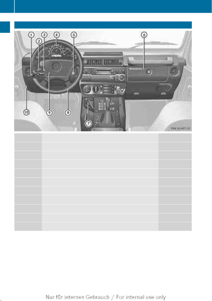
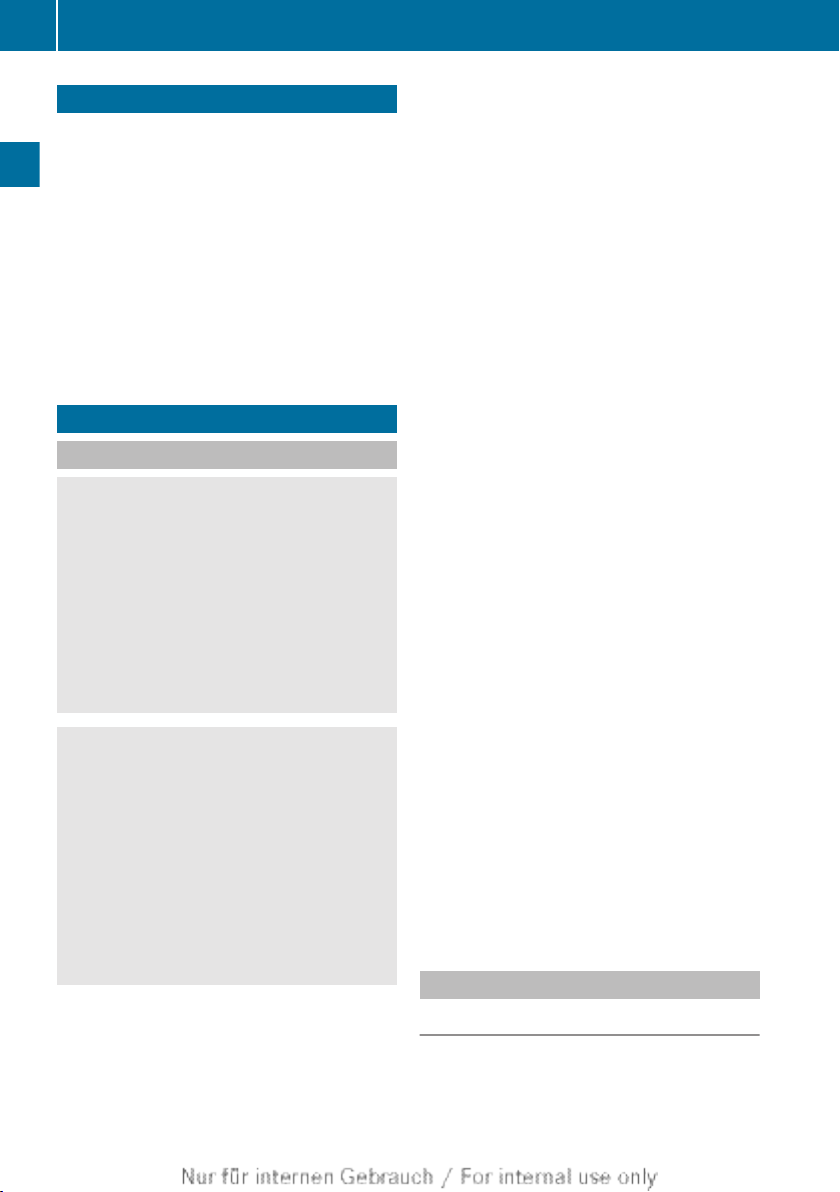
Cockpit
18
Cockpit
At a glance
:
;
=
?
A
B
C
D
E
F
Function Page
Combination switch 60
Adjusts the headlamp range 61
Emergency start facility 163
Instrument cluster 19
Ignition lock 87
Glove compartment 130
Battery main switch
1
87
Steering wheel
Horn
Opening the bonnet 140
1
Only for 24 V electrical system.
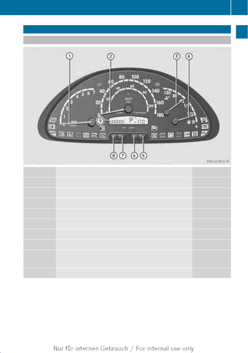
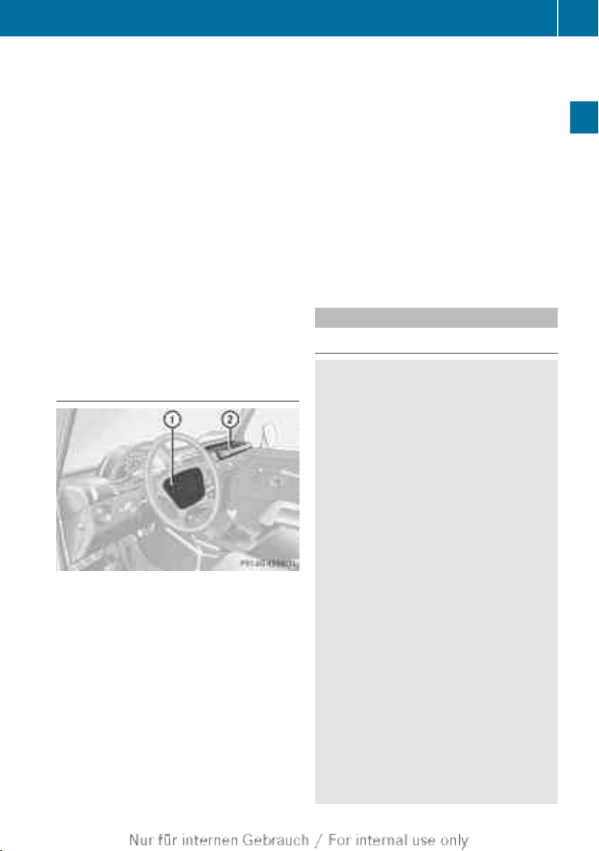
Instrument cluster
Displays and controls
Function Page
:
;
=
?
A
B
C
D
E
Rev counter 118
Speedometer
Coolant temperature gauge 118
Fuel gauge
Adjusts the instrument cluster lighting: brighter 119
Adjusts the instrument cluster lighting: dimmer 119
Inoperative
Total distance recorder/trip meter selector button 119
Reset button
Display
Instrument cluster
19
At a glance
Instrument cluster
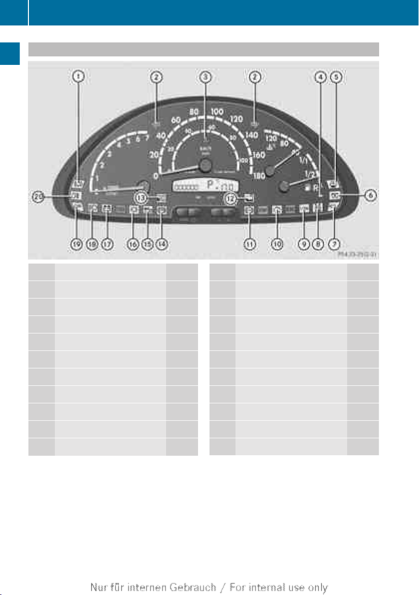
20
Warning and indicator lamps
At a glance
Function Page
:
Brakes 120
;
Turn signals 60
=
ABS warning lamp 121
?
Reserve fuel 122
A
Washer fluid level 125
B
Preglow 122
C
ADR 95
D
Air filter 124
E
Transfer case 125
F
Engine diagnostics
122
Function Page
G
ABS indicator lamp 120
H
Coolant
I
Fuel/water separator 124
J
Parking brake 122
K
Oil level 124
L
Brake pad wear indicator
M
Battery 123
N
Main-beam headlamps 60
O
SRS 122
P
Rear foglamp 60
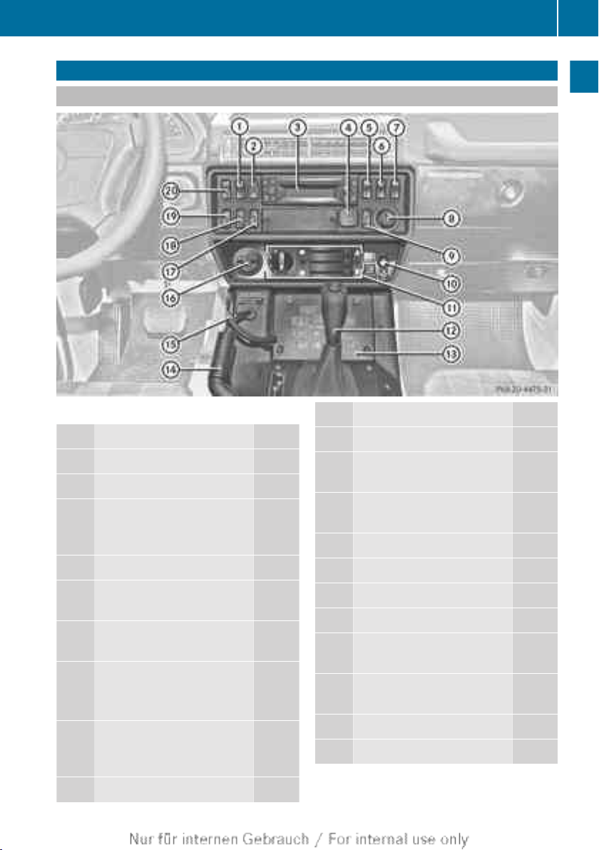
Centre console
Overview
i
Example: centre console overview
Function Page
:
Rear foglamp 60
;
Hazard warning lamps 61
=
CD/radio player; see the
separate operating instructions
?
12 V socket 136
A
Activates/deactivates ADR
(working speed governor) 95
B
Adjusts ADR (working
speed governor) 95
C
Switch for cable-winch
socket/ 137
Jump starting socket 165
D
Increases/reduces the
temperature (air-conditioning system) 80
E
Air-recirculation mode
81
Centre console
Function Page
F
24 V power socket 136
G
Heating and air-conditioning system control panel 79
H
Automatic transmission
selector lever 91
I
Control panel 22
J
Parking brake 101
K
Battery main switch 87
L
Light switch 58
M
Switches the rear window
wiper on/off 74
N
Washes the rear window
with washer fluid 74
O
Rear window heating 81
P
Foglamps 60
21
At a glance
Centre console
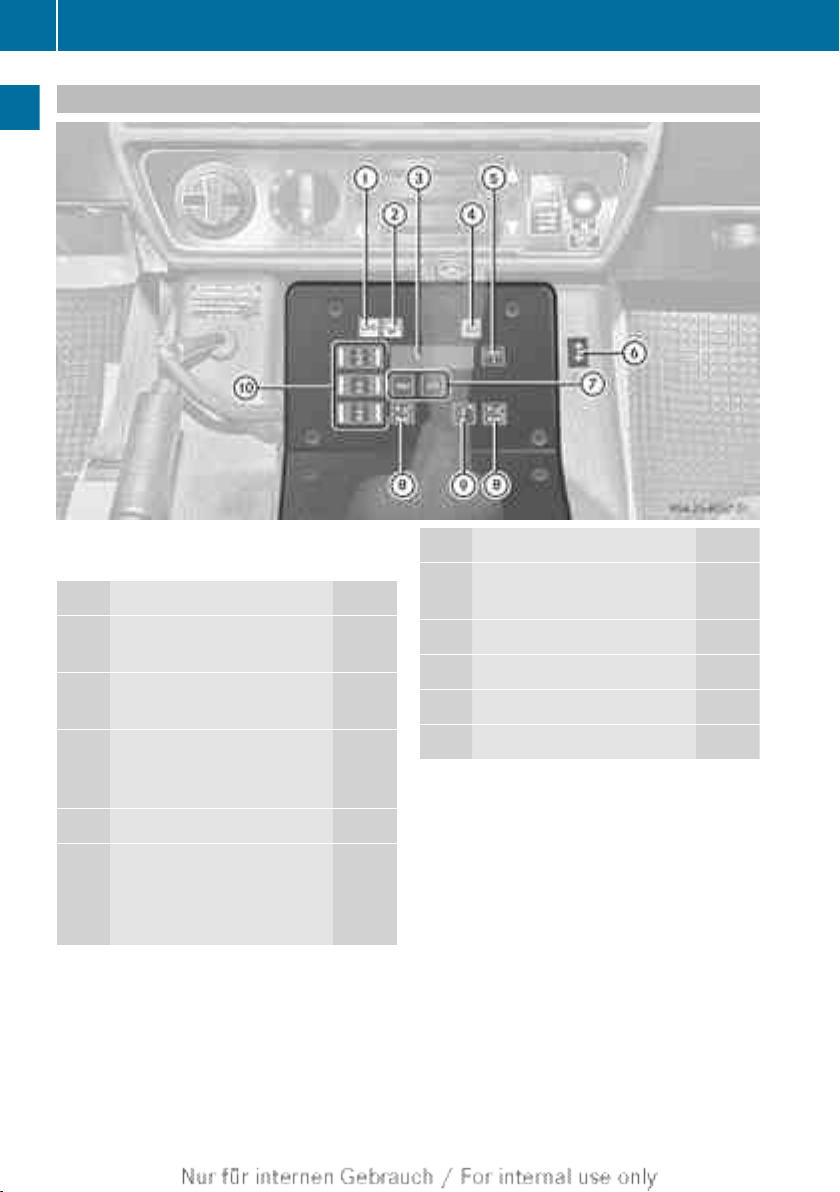
22
Lower section with control panel
At a glance
i
Centre console, lower section with con-
trol panel (example)
Function Page
:
24 V turn signal indicator
lamp for trailer towing
;
24 V battery charge warning lamp 163
=
Display for 12 V/24 V battery voltage and operating
hours counter
?
Foglamp indicator lamp 60
A
Switches display between
12 V/24 V battery voltage
and operating hours counter
Function Page
B
12 V turn signal indicator
lamp for trailer towing
C
Engages the transfer case 110
D
Seat heating 53
E
Auxiliary heating 82
F
Engages differential locks 112

Useful information .............................. 24
Occupant safety .................................. 24
Children in the vehicle ........................ 29
Driving safety systems ....................... 35
Anti-theft systems .............................. 36
23
Safety
Occupant safety
24
Useful information
i
This Owner's Manual describes all models, series and optional equipment for your
vehicle that were available at the time of
going to press. Country-specific differences are possible. Note that your vehicle
may not be fitted with all features descri-
Safety
bed. This is also the case for systems and
functions relevant to safety.
i
Read the information on qualified specialist workshops: (Y page 15).
Occupant safety
Important safety notes
WARNING
G
If service work is not carried out correctly, the
operating safety of your vehicle may be affected. This could cause you to lose control of
your vehicle and cause an accident. Moreover, the safety systems may no longer be
able to protect you or others as they are
designed to do.
Always have service work carried out at a
qualified specialist workshop.
WARNING
G
Modifications to the restraint systems could
result in them not functioning properly any
more. The restraint systems could then no
longer protect vehicle occupants as they are
designed to do and could fail in the event of
an accident or activate unexpectedly, for
example. There is an increased risk of injury.
Never modify parts of the restraint systems.
Do not attempt to modify the wiring as well as
electronic components or their software.
The airbag system can be adapted for a person with disabilities. For further information,
consult a Mercedes-Benz Service Centre.
Seat belts, together with the Supplemental
Restraint System, SRS (Y page 24), are
complementary, co-ordinated restraint sys-
tems. They reduce the risk of injury in specific, pre-defined types of accident situations
and thereby increase occupant safety. However, seat belts and airbags generally do not
protect against objects penetrating the vehicle from the outside.
To ensure that the restraint systems can
deliver their full potential protection, make
sure that:
R
the seat and head restraint are adjusted
properly (Y page 50)
R
the seat belt has been fastened properly
(Y page 29)
R
the airbags can inflate unrestricted if
deployed (Y page 26)
R
the restraint systems have not been modified
An airbag increases the protection of vehicle
occupants wearing a seat belt. However, airbags are only an additional restraint system
which complements, but does not replace,
the seat belt. All vehicle occupants must wear
their seat belt correctly at all times, even if
the vehicle is equipped with airbags. The airbags are not deployed in all types of accidents. For example, if the protective capacity
of correctly fastened seat belts is not
increased by deploying the airbags, the airbags will not deploy.
Airbag deployment only provides increased
protection if the seat belt is worn correctly.
The seat belt helps, firstly, to keep the vehicle
occupant in the best position in relation to the
airbag. Secondly, in a head-on collision, for
example, the seat belt prevents the vehicle
occupant from being propelled towards the
point of impact.
SRS (Supplemental Restraint System)
Introduction
SRS reduces the risk of occupants coming
into contact with the vehicle's interior in the
event of an accident. It can also reduce the

Occupant safety
25
forces to which occupants are subjected during an accident.
SRS consists of:
R
SRS warning lamps +
R
airbags
R
airbag control unit
SRS warning lamp
WARNING
G
If SRS is malfunctioning, child restraint system components may be triggered unintentionally or might not be triggered at all in the
event of an accident with a high rate of vehicle
deceleration. There is an increased risk of
injury, possibly even fatal.
Have SRS checked and repaired immediately
at a qualified specialist workshop.
A malfunction has occurred if the + warn-
ing lamp:
R
does not go out after three seconds when
you turn the key to position 1 in the ignition
lock (self diagnosis)
R
does not go on when you turn the key to
position 2 in the ignition lock
R
does not go out after the engine has been
running for a few seconds
R
lights up again
Airbag deployment
During the first stage of a collision, the airbag
control unit evaluates important physical
data relating to vehicle deceleration or acceleration, such as:
R
duration
R
direction
R
magnitude
Based on the evaluation of this data, the airbag control unit triggers the front airbags in
the event of a collision with a very high rate
of deceleration or acceleration in a longitudinal direction. In the event of a collision, the
front airbags inflate with the maximum
amount of gas within a few milliseconds.
i
Airbags are not deployed in all types of
accidents. Also, not all airbags are
deployed together in an accident. The different airbag systems work independently
of each other.
How the airbag system works is determined by the severity of the collision detected, especially the vehicle deceleration or
acceleration, and the apparent type of accident:
R
head-on collision
R
rear impact
The rate of vehicle deceleration or acceleration and the direction of the force are essentially determined by:
R
the distribution of forces during the collision
R
the collision angle
R
the deformation characteristics of the vehicle
R
the characteristics of the object with which
the vehicle has collided
Factors which can only be seen and measured
after a collision has occurred do not play a
decisive role in the deployment of an airbag,
nor do they provide an indication of airbag
deployment.
The vehicle may be deformed significantly,
e.g. the bonnet or the wing, without an airbag
being deployed. This is the case if only parts
which are relatively easily deformed are affected and the rate of deceleration is not high.
Conversely, airbags may be deployed even
though the vehicle suffers only minor deformation. This is the case if, for example, very
rigid vehicle parts such as longitudinal body
members are hit, and sufficient deceleration
occurs as a result.
Safety
Z

Occupant safety
26
Airbags
Important safety notes
WARNING
G
Airbags provide additional protection; they
are not, however, a substitute for seat belts.
Observe the following notes to reduce the risk
Safety
of serious or even fatal injury caused by airbag
deployment:
R
all vehicle occupants – in particular, pregnant women – must wear their seat belt
correctly at all times and lean back against
the backrest, which should be positioned
as close to the vertical as possible. The
head restraint must support the back of the
head at about eye level.
R
always secure children less than 1.50 m tall
and under 12 years of age in suitable child
restraint systems.
R
the driver and front passenger must select
a seat position that is as far away from the
airbag as possible. The driver's seat position must allow the vehicle to be driven
safely. The driver's chest should be as far
away from the centre of the driver's airbag
cover as possible.
R
move the front-passenger seat as far back
as possible. This is especially important if
you have secured a child in a forward-facing
child restraint system on the frontpassenger seat.
R
a rearward-facing child restraint system
must never be secured on the frontpassenger seat.
R
make sure there are no heavy or sharpedged objects in the pockets of clothing.
R
do not lean forwards, e.g. over the cover of
the driver's/front-passenger front airbag,
particularly when the vehicle is in motion.
R
do not put your feet on the dashboard.
R
only hold the steering wheel on the outside.
This allows the airbag to be fully deployed.
You could be injured if the airbag is
deployed and you are holding the inside of
the steering wheel.
R
do not lean on the doors from inside the
vehicle.
R
make sure that there are no people, animals or objects between the driver, front
passenger and the area where the airbags
are deployed.
R
do not place any objects between the seat
backrest and the door.
R
do not hang any hard objects, e.g. coat
hangers, on the grab handles or coat hooks.
R
do not attach accessories, e.g. cup holders,
to the doors.
It is not possible to rule out a risk of injury
being caused by an airbag, due to the high
speed at which the airbag must be deployed.
WARNING
G
If you modify the airbag covers or affix
objects, e.g. stickers to them, the airbags may
no longer function as intended. There is an
increased risk of injury.
Never modify the airbag covers and do not
affix any objects to them.
WARNING
G
After the driver's airbag has been deployed,
the airbag parts are hot. There is a risk of
injury.
Do not touch the airbag parts. Have deployed
airbags replaced immediately at a qualified
specialist workshop.
i
Have the vehicle towed to a qualified specialist workshop after the airbags have
been deployed.
Occupant safety
27
If an airbag deploys, you will hear a bang and
a small amount of powder is released. Only in
rare cases will the bang affect your hearing.
The powder that is released generally does
not constitute a health hazard. The +
warning lamp lights up. If it is safe to do so:
X
Leave the vehicle as soon as possible.
If you are unable to leave the vehicle:
X
Open a window.
You will get fresh air and avoid breathing
difficulties.
Your vehicle is equipped with a driver's and
front-passenger's front airbag.
Airbag deployment slows down and restricts
the movement of the vehicle occupant.
The installation locations of the airbags can
be found in the "Front airbags" section
(Y page 27).
Front airbags
Driver's airbag : deploys in front of the
steering wheel; front-passenger front airbag ; deploys in front of and above the glove
compartment.
The front airbags increase protection for the
driver's and front-passenger's head, neck and
chest.
They are deployed:
R
at the start of an accident with a high rate
of vehicle acceleration or deceleration in a
longitudinal direction
R
if the system determines that airbag
deployment can offer additional protection
to that provided by the seat belt
R
depending on whether the seat belt is being
used
If the vehicle overturns, the front airbags are
generally not deployed. The front airbags are
deployed if the system detects high vehicle
deceleration in a longitudinal direction.
Seat belts
Important safety notes
WARNING
G
A seat belt which is not worn correctly, or
which has not been engaged in the seat belt
buckle correctly, cannot provide the intended
level of protection. Under certain circumstances, this could cause severe or even fatal injuries in the event of an accident.
Therefore, make sure that all occupants — in
particular, pregnant women — wear their seat
belts correctly at all times.
R
The seat belt must fit snugly on your body
and must not be twisted.Therefore, avoid
wearing bulky clothing, e.g. a winter coat.
The shoulder section of the belt must be
routed across the centre of your shoulder
— on no account across your neck or under
your arm — and pulled tight against your
upper body. The lap belt must always pass
across your lap as low down as possible, i.e.
over your hip joints — not across your abdomen. If necessary, push the seat belt
slightly downwards and adjust it by pulling
it in the direction the seat belt retracts.
R
Do not route the seat belt strap over sharp
or fragile objects. Please make sure that
such objects are not on or in your clothing,
e.g. spectacles, pens or keys etc. The seat
Safety
Z

Occupant safety
28
belt strap could become damaged and tear
during an accident and you or other vehicle
occupants could be injured.
R
Only one person should use each seat belt
at any one time. Children must never travel
sitting on the lap of another occupant. The
child will not be secured in the event of an
accident, heavy braking or sudden change
Safety
of direction. This may result in the child or
other occupants being seriously or fatally
injured.
R
Persons under 1.50 m tall cannot wear the
seat belts correctly. For this reason secure
persons less than 1.50 m tall in specially
designed, suitable restraint systems.
R
Children under 1.50 m tall and younger
than twelve years of age cannot wear the
seat belts correctly. For this reason secure
them in special suitable child restraint systems installed on a suitable seat. Additional
information can be found in the Operating
Instructions in the chapter "Safety", "Children in the Vehicle". Observe the installation instructions of the child restraint system manufacturer.
R
Do not secure an object with a seat belt if
the seat belt is also being used by one of
the vehicle's occupants.
WARNING
G
The seat belt does not offer the intended level
of protection if the backrest is not in the
upright position. When braking or in the event
of an accident, you could slide underneath the
seat belt and sustain abdomen or neck injuries, for example. This poses an increased risk
of injury or even fatal injury.
Adjust the seat properly before beginning
your journey. Always make sure that the seat
is in the upright position.
WARNING
G
Seat belts cannot perform their intended protective function if:
R
they are damaged, modified, bleached or
coloured, or are very dirty
R
the seat belt buckle is damaged or very
dirty
R
modifications have been made to the seat
belt tensioners or belt anchorages
In the event of an accident, seat belts can
sustain damage that is not visible to the naked
eye, e. g. due to glass splinters. Modified or
damaged seat belts could tear or fail in the
event of an accident, for example. Modified
belt tensioners could deploy unexpectedly or
fail. There is an increased risk of serious or
even fatal injuries.
Never make modifications to seat belts, belt
tensioners, belt anchorages or seat belt
retractors. Make sure that the seat belts are
undamaged, are not worn and are clean.
Mercedes-Benz recommends that you only
use seat belts which have been approved
specifically for your vehicle by MercedesBenz.
The three-point seat belt provides better
restraint than the lap belt and therefore provides better protection against injuries. Passengers on the rear seats should therefore
use the seats with three-point seat belts when
possible.
Seat belts are the most effective means of
restraining the movement of vehicle occupants in the event of an accident. This
reduces the risk of vehicle occupants coming
into contact with parts of the vehicle interior.

Fastening seat belts
Three-point seat belt
Children in the vehicle
X
Press release button : of belt buckle =
and guide belt tongue ; back towards belt
sash guide.
Children in the vehicle
29
Example: three-point seat belt, front
X
Adjust the seat and move the backrest to
an almost vertical position (Y page 50).
X
Pull the seat belt smoothly from the inertia
reel.
X
Without twisting it, guide the shoulder section of the seat belt across the middle of
your shoulder and the lap section across
your hips.
X
Engage belt tongue ; in buckle =.
X
If necessary, pull upwards on the shoulder
section of the seat belt to tighten the belt
across your body.
For more information about releasing the seat
belt with release button :, see "Releasing
seat belts" (Y page 29).
Releasing the seat belts
!
Make sure that the seat belt is fully rolled
up. Otherwise, the seat belt or belt tongue
will be trapped in the door or in the seat
mechanism. This could damage the door,
the door trim panel and the seat belt. Damaged seat belts can no longer fulfil their
protective function and must be replaced.
Visit a qualified specialist workshop.
Child restraint systems
Important safety notes
WARNING
G
To reduce the risk of serious or even fatal
injury to the child in the event of a sudden
change in direction, braking or an accident:
R
Children less than 1.50 m tall and under
twelve years of age must always be secured
in special child restraint systems on a suitable vehicle seat. This is necessary
because the seat belts are not designed for
children.
R
Children must never travel sitting on the lap
of another occupant. Due to the forces
which occur in the event of a sudden
change of direction, heavy braking or an
accident, it would not be possible to
restrain the child. The child could be thrown
against parts of the vehicle interior and be
seriously or even fatally injured.
WARNING
G
The child restraint system cannot perform its
protective function if it is not correctly fitted
to a suitable vehicle seat. The child cannot be
restrained in the event of an accident, heavy
braking or sudden changes of direction. The
child could be seriously or even fatally injured.
For this reason, when fitting a child restraint
system, observe the manufacturer's installation instructions and the correct use of the
child restraint system.
Child restraint systems should be fitted to the
rear seats. Children are generally better protected there.
The entire base of the child restraint system
must always rest on the seat cushion. There-
Safety
Z

Children in the vehicle
30
fore, never place objects, e.g. a cushion,
under the child restraint system.
Only use child restraint systems with the original cover designed for them. Only replace
damaged covers with genuine Mercedes-Benz
covers.
We recommend the use of child restraint systems which have been approved for
Safety
Mercedes-Benz vehicles.
WARNING
G
If the child restraint system is fitted incorrectly or is not secured, it can come loose in
the event of an accident, heavy braking or a
sudden change in direction. The child
restraint system could be thrown about, striking vehicle occupants. There is an increased
risk of injury, possibly even fatal.
Always fit child restraint systems properly,
even if they are not being used. Make sure
that you observe the child restraint system
manufacturer's installation instructions.
If a child is travelling in your vehicle, secure
the child using a child restraint system which
is appropriate to the size, age and weight of
the child and recommended for MercedesBenz vehicles. You should preferably fit the
restraint system to a suitable rear seat. Make
sure that the child is secured in a child
restraint system throughout the trip.
Mercedes-Benz recommends that you only
use the listed child restraint systems
(Y page 34).
You can obtain information about the correct
child restraint system from any MercedesBenz Service Centre.
i
It is advisable to use Mercedes-Benz care
products to clean child restraint systems.
You can obtain information about this at
any Mercedes-Benz Service Centre.
Child restraint system on the frontpassenger seat
WARNING
G
If the front-passenger front airbag is not disabled:
R
a child secured in a child restraint system
on the front-passenger seat could be seriously or even fatally injured by the frontpassenger airbag deploying. This is especially a risk if the child is in the immediate
vicinity of the front-passenger front airbag
when it deploys.
R
never secure a child on the front-passenger
seat in a rearward-facing child restraint system. Only secure a rearward-facing child
restraint system on a suitable rear seat.
R
always move the front-passenger seat to
the rearmost position if you secure a child
in a forward-facing child restraint system
on the front-passenger seat.
Information about recommended child
restraint systems is available at any
Mercedes-Benz Service Centre.
The vehicle has no automatic child seat recognition and the front-passenger front airbag
cannot be manually deactivated.
Warning symbol for a rearward-facing child
restraint system
Do not use a rearward-facing child restraint
system on a seat that is protected by an airbag installed in front of it.

Children in the vehicle
31
ISOFIX child seat securing system for
the rear seats
WARNING
G
ISOFIX child restraint systems do not provide
sufficient protection for children weighing
more than 22 kg. The child cannot be
restrained in the event of an accident, for
instance. There is an increased risk of injury,
possibly even fatal.
If the child weighs more than 22 kg, secure
the ISOFIX child restraint system additionally
with the seat belt. If available, secure the child
restraint system additionally with the Top
Tether belt.
WARNING
G
The child restraint system cannot perform its
protective function if it is not correctly fitted
to a suitable vehicle seat. The child cannot be
restrained in the event of an accident, heavy
braking or sudden changes of direction. The
child could be seriously or even fatally injured.
For this reason, when fitting a child restraint
system, be sure to observe the manufacturer's installation instructions and the instructions for correct use of the child restraint system.
For safety reasons, when installing child
restraint systems on the rear seats, only use
child restraint systems with the ISOFIX child
seat securing system, which are specially tested and approved for Mercedes-Benz vehicles.
An incorrectly fitted child restraint system
could come loose and seriously or even fatally
injure the child or other vehicle occupants.
When fitting the child restraint system, always
make sure that it is engaged correctly in the
securing rings on both sides.
ISOFIX is a standardised securing system for
specially designed child restraint systems on
the rear seats. Securing rings for two ISOFIX
child restraint systems are fitted on the left
and right of the rear seats.
Before every trip, make sure that the ISOFIX
child restraint system is engaged correctly in
both securing rings
When fitting a child restraint system, be sure
to observe the manufacturer's installation
instructions and the instructions for correct
use of the child restraint system.
Example: rear bench seat, front-passenger side
:
Securing rings
X
Install the ISOFIX child restraint system.
Comply with the manufacturer's instructions when installing the ISOFIX child
restraint system.
Top Tether
WARNING
G
If you secure the Top Tether belt incorrectly,
e.g. to the loop underneath the Top Tether
anchorage, the child restraint system is not
correctly kept in place. It therefore cannot
perform its intended protective function in the
event of an accident. This poses an increased
risk of injury.
Only secure the Top Tether hook to the intended Top Tether anchorage.
Top Tether provides an additional connection
between the child restraint system secured
with ISOFIX and the rear seat. It helps reduce
the risk of injury even further.
Safety
Z

Children in the vehicle
32
Safety
Example: vehicles with a 12 V electrical system
X
Move the head restraint upwards.
X
Fit the ISOFIX child restraint system with
Top Tether. Comply with the manufacturer's installation instructions when doing so.
X
Route Top Tether belt = under the head
restraint between the two head restraint
bars.
X
Hook Top Tether hook : to Top Tether
anchorage ; on the side wall.
X
Hook Top Tether hook : of Top Tether belt
= into Top Tether anchorage ;.
Ensure that:
R
Top Tether hook : is hooked into Top
Tether anchorage ; as shown
R
Top Tether belt = is not twisted
X
Make sure that Top Tether belt = is not
twisted.
X
Tension Top Tether belt =. Comply with
the manufacturer's installation instructions when doing so.
X
Move the head restraint back down again
slightly if necessary (Y page 52). Make
sure that you do not interfere with the correct routing of Top Tether belt =.

Suitable positioning of the child restraint systems
Children in the vehicle
33
Weight categories and ages Category 0: up to 10 kg
up to approximately
9 months
Child restraint system on the
front-passenger seat
2
Child restraint system on the
Not suitable Not suitable
Universal Universal
Category 0+: up to 13 kg
up to approximately
18 months
left-hand and right-hand
sides of the rear bench
3
seat
Weight categories and ages Category I: 9 to 18 kg
between approximately
8 months and 4 years
Category II/III: 15 to
36 kg
between approximately
3.5and 12 years
Child restraint system on the
front-passenger seat
2
Child restraint system on the
Universal, forward-facing Universal
Universal Universal
left-hand and right-hand rear
3
seats
"Universal" category child restraint systems can be recognised by their orange approval label
with the inscription "universal".
Safety
Example: approval label on the child restraint system
2
Move the front-passenger seat to its rearmost position.
3
Vehicles with rear seats only.
Z

Children in the vehicle
34
Recommended child restraint systems
Weight categories and ages
Manufacturer
Type
Safety
Approval number
Category 0: up to 10 kg
up to approximately 9 months
Britax Römer Britax Römer
BABY SAFE PLUS BABY SAFE PLUS
E1 03 301146
E1 04 301146
Order number
Weight categories and ages
A000 970 10 00 A000 970 10 00
Category I: 9 to 18 kg
between approximately 8 months
and 4 years
Manufacturer
Type
Approval number
Order number
Britax Römer Britax Römer
DUO PLUS KIDFIX
E1 03 301133
E1 04 301133
A000 970 16 00 A000 970 19 00
Child-proof locks for the rear side
doors and rear door
WARNING
G
If children are travelling in the vehicle, they
could:
R
open doors, thus endangering other people
or road users
R
exit the vehicle and be caught by oncoming
traffic
R
operate vehicle equipment and become
trapped, for example
There is a risk of an accident and injury.
Always activate the child-proof locks and
override feature if children are travelling in the
vehicle. When leaving the vehicle, always take
the key with you and lock the vehicle. Never
leave children unattended in the vehicle.
Category 0+: up to 13 kg
up to approximately 18 months
E1 03 301146
E1 04 301146
Category II/III: 15 to 36 kg
between approximately
3.5and 12 years
E1 04 301198
A door secured with a child-proof lock cannot
be opened from inside the vehicle. When the
vehicle is unlocked, the door can only be
opened from the outside.
i
The chassis cab 6x6 with crewcab has no
child-proof locks on the rear doors.
Example: rear side door
The station wagon has a child-proof lock on
the rear doors and the tailgate.

X
To activate: press the child-proof lock
lever down in the direction of arrow ;.
X
Make sure that the child-proof locks are
working properly.
X
To deactivate: press the child-proof lock
lever up in the direction of arrow :.
Driving safety systems
Driving safety systems overview
In this section, you will find information about
the following driving safety systems:
R
ABS (Anti-lock Braking System)
R
BAS (Brake Assist System)
R
EBD (electronic brake force distribution)
Important safety notes
If you fail to adapt your driving style, the driving safety systems can neither reduce the risk
of accident nor override the laws of physics.
Driving safety systems are merely aids
designed to assist driving. You are responsible for the distance to the vehicle in front, for
vehicle speed and for braking in good time.
Always adapt your driving style to suit the
prevailing road and weather conditions as
well as the traffic conditions, and maintain a
safe distance from the vehicle in front. Drive
carefully.
i
Please note that the driving safety systems described only work as effectively as
possible when there is adequate contact
between the tyres and the road surface.
Pay particular attention to the information
regarding tyres, recommended minimum
tyre tread depths etc. in the "Wheels and
tyres" section (Y page 174).
In wintry driving conditions, always use
winter tyres (M+S tyres) and, if necessary,
snow chains. Only in this way will the driving safety systems described in this section
work as effectively as possible.
Driving safety systems
ABS (Anti-lock Braking System)
Important safety notes
i
Observe the "Important safety notes" sec-
tion (Y page 35).
WARNING
G
If ABS is faulty, the wheels could lock when
braking. The steerability and braking characteristics may be severely impaired. Additionally, further driving safety systems are deactivated. There is an increased danger of skidding and accidents.
Drive on carefully. Have ABS checked immediately at a qualified specialist workshop.
ABS regulates brake pressure in such a way
that the wheels do not lock when you brake.
This allows you to continue steering the vehicle when braking.
ABS works from a speed of about
8 km/hupwards, regardless of road-surface
conditions. ABS intervenes on slippery road
surfaces, even when you only brake gently.
The ! indicator lamp in the instrument
cluster (Y page 20) lights up briefly when the
engine is started. This indicates that ABS is
operational.
Braking
!
If a blackout lighting setting is selected,
the button illumination and instrument
cluster lighting are switched off.
You will not be informed that the differential locks are engaged and that ABS is
switched off. If you do not adapt your driving style accordingly, you could damage the
transfer case.
If ABS intervenes when braking, you will feel
a pulsing in the brake pedal.
X
If ABS intervenes: continue to depress the
brake pedal with force until the braking situation is over.
X
To make a full brake application:
depress the brake pedal with full force.
35
Safety
Z

Anti-theft systems
36
The pulsating brake pedal can be an indication of hazardous road conditions, and functions as a reminder to take extra care while
driving.
i
If ABS is malfunctioning, the ! indicator lamp and the J warning lamp, or just
the ! indicator lamp in the instrument
cluster light up.
Safety
When the differential locks are engaged,
ABS is switched off. The ! indicator
lamp and the d warning lamp light up in
the instrument cluster.
Normal driving and braking functions are
still available.
BAS (Brake Assist System)
i
Observe the "Important safety notes" section (Y page 35).
WARNING
G
If BAS is malfunctioning, the braking distance
in an emergency braking situation is
increased. There is a risk of accident.
In an emergency braking situation, depress
the brake pedal with full force. ABS prevents
the wheels from locking.
WARNING
G
If EBD has malfunctioned, the rear wheels can
still lock, e.g. under full braking. This increases the risk of skidding and an accident.
You should therefore adapt your driving style
to the different handling characteristics. Have
the brake system checked at a qualified specialist workshop.
Observe information regarding indicator and
warning lamps (Y page 120).
EBD monitors and controls the brake pressure on the rear wheels to improve driving
stability while braking.
Anti-theft systems
Immobiliser
X
To activate: remove the key from the ignition lock.
X
To deactivate: switch on the ignition.
The immobiliser prevents your vehicle from
being started without the correct key.
i
The immobiliser is always deactivated
when you start the engine.
BAS operates in emergency braking situations. If you depress the brake pedal quickly,
BAS automatically boosts the braking force,
thus shortening the stopping distance.
X
Keep the brake pedal depressed firmly until
the emergency braking situation is over.
ABS prevents the wheels from locking.
The brakes will function as usual once you
release the brake pedal. BAS is deactivated.
EBD (electronic brake force distribution)
i
Observe the "Important safety notes" section (Y page 35).

Useful information .............................. 38
Key ....................................................... 38
Doors .................................................... 39
Rear door ............................................. 40
Split rear door ..................................... 42
Platform truck dropsides ................... 44
Windows .............................................. 46
37
Opening and closing

Key
38
Useful information
i
This Owner's Manual describes all models, series and optional equipment for your
vehicle that were available at the time of
going to press. Country-specific differences are possible. Note that your vehicle
may not be fitted with all features described. This is also the case for systems and
functions relevant to safety.
i
Read the information on qualified specialist workshops: (Y page 15).
Key
Unlocking/locking the vehicle
Opening and closing
WARNING
G
If children are left unsupervised in the vehicle,
they can:
R
open doors and endanger other persons or
road users
R
climb out and be injured by the traffic
R
operate vehicle equipment and, for example, trap themselves.
Children could also set the vehicle in motion,
for example by:
R
releasing the parking brake
R
shifting the automatic transmission out of
park position P
R
starting the engine.
There is a risk of an accident and injury.
When leaving the vehicle, always take the key
with you and lock the vehicle. Never leave
children unattended in the vehicle. Always
keep the key out of reach of children.
Key
X
To unlock the vehicle: insert the key into
the door lock.
X
Turn the key anti-clockwise.
X
To lock the vehicle: insert the key into the
door lock.
X
Turn the key clockwise.
i
The key fits all the door locks (except the
glove compartment) and the fuel filler cap
of the vehicle.

Problems with the key
Problem Possible causes/consequences and M Solutions
Doors
39
You have lost the key.
X
Report the loss immediately to the vehicle insurers.
X
If necessary, have the locks changed as well.
Doors
Unlocking and opening the doors
from the inside
You can open a door from inside the vehicle
at any time, even if it has been locked.
You can only open the rear compartment
doors from inside the vehicle if they are not
secured by the child-proof locks (Y page 34).
:
To unlock
;
To lock
=
Door handle
X
Push the latch upwards :.
The door is unlocked and can be opened.
X
Pull door handle = and open the door.
i
If you open a locked door from inside the
vehicle, it is unlocked automatically.
i
You can only open a locked rear door from
inside the vehicle if the child-proof locks
have not been activated.
Centrally locking and unlocking the
vehicle from the inside
WARNING
G
If children are left unsupervised in the vehicle,
they could:
R
open the doors, thus endangering other
people or road users.
R
get out and disrupt traffic.
R
operate the vehicle's equipment.
Additionally, children could set the vehicle in
motion if, for example, they:
R
release the parking brake.
R
shift the automatic transmission out of
parking position P.
R
shift the manual transmission into neutral.
R
start the engine.
There is a risk of an accident and injury.
When leaving the vehicle, always take the key
with you and lock the vehicle. Never leave
children or animals unattended in the vehicle.
Always keep the key out of reach of children.
You can centrally lock or unlock the vehicle
from the inside.
The button for the central locking does not
lock or unlock the fuel filler flap.
The switch for the central locking is on the
lower section of the centre console.
Opening and closing
Z

Rear door
40
Example: station wagon
X
To unlock: press button :.
X
To lock: press button ;.
i
It is only possible to lock the vehicle cen-
trally if the driver's door is closed.
Opening and closing
i
The doors unlock automatically in the
event of an accident if the force of the
impact exceeds a predetermined level.
Rear door
Additionally, children could set the vehicle in
motion if, for example, they:
R
release the parking brake.
R
shift the automatic transmission out of
parking position P.
R
shift the manual transmission into neutral.
R
start the engine.
There is a risk of an accident and injury.
When leaving the vehicle, always take the key
with you and lock the vehicle. Never leave
children or animals unattended in the vehicle.
Always keep the key out of reach of children.
Opening from the outside
You can only open the rear door after unlocking it first.
Important safety notes
WARNING
G
Combustion engines emit poisonous exhaust
gases such as carbon monoxide. If the tailgate/rear door is open when the engine is
running, particularly if the vehicle is moving,
exhaust fumes could enter the passenger
compartment. There is a risk of poisoning.
Turn off the engine before opening the tailgate/rear door. Never drive off with the tailgate/rear door open.
WARNING
G
If children are left unsupervised in the vehicle,
they could:
R
open the doors, thus endangering other
people or road users.
R
get out and disrupt traffic.
R
operate the vehicle's equipment.
1
To unlock
2
To lock
X
Insert the key into the door lock.
X
Turn the key anti-clockwise 1.
The rear door is unlocked.
X
Remove the key.
or
X
Unlock the vehicle centrally from the inside
(Y page 39).

X
Press lock cylinder ? and pull door handle
=.
Entering/exiting through the rear
door
Rear door
Opening from the inside
:
To unlock
;
To lock
=
Door handle
X
Slide latch : upwards.
The door is unlocked.
X
Pull door handle =.
i
If the child-proof locks (Y page 34) are
used to secure the rear door, you cannot
open it from inside the vehicle, even when
it has been unlocked.
41
Opening and closing
Example: station wagon
X
Open the rear door.
X
Hold on to grab handle : and tread on
step ; on the bumper.
Closing from the outside
X
Close the rear door.
X
Insert the key into the door lock.
X
Turn the key clockwise.
The rear door is locked.
Z

Split rear door
42
Closing from inside the vehicle
:
To unlock
;
To lock
=
Door handle
X
Secure the rear door with the child-proof
locks if necessary (Y page 34).
Opening and closing
X
Pull the rear door closed using the handle
underneath the rear window.
X
Push the latch downwards ;.
The rear door is locked.
Split rear door
Swinging the spare wheel bracket to
one side
!
Make sure that there is sufficient clear-
ance.
WARNING
G
If the exterior spare wheel bracket has been
moved to one side, the tail lamp may be covered. Other road users may not recognise the
vehicle and, as a result, crash into your vehicle
from the rear. Secure the vehicle additionally
with a warning lamp or a warning triangle.
Do not drive the vehicle if the spare wheel
bracket is folded away from the vehicle.
Make sure that the spare wheel bracket is
closed correctly.
You could otherwise injure people or cause an
accident due to the flailing action of the spare
wheel bracket.
X
Raise safety catch : and pull lever ; in
the direction of the arrow.
X
Swing spare wheel bracket = to one side.
Opening from the outside
WARNING
G
Combustion engines emit poisonous exhaust
gases such as carbon monoxide. If the tailgate/rear door is open when the engine is
running, particularly if the vehicle is moving,
exhaust fumes could enter the passenger
compartment. There is a risk of poisoning.
Turn off the engine before opening the tailgate/rear door. Never drive off with the tailgate/rear door open.
!
Make sure that you first open the lefthand rear door and then the right-hand rear
door. You could otherwise damage the rear
doors.
!
Make sure that there is sufficient clearance.
X
Insert the key into the door lock.
X
Turn the key anti-clockwise.
The rear door is unlocked.
X
Remove the key.

X
Press lock cylinder : and pull door handle ;.
X
Open the left half of the rear door to the
left.
X
Swing the spare wheel bracket to one side
(Y page 42).
Split rear door
Entering/exiting through the rear
door
X
Swing the spare wheel bracket to one side.
X
Open the left and right halves of the split
rear door.
X
When entering or exiting the vehicle, hold
on to grab handle : on the rear wall and
use step ; above the trailer tow hitch.
43
Opening and closing
X
Press lever = in the direction of the arrow
and open the right half of the rear door to
the right.
Opening from the inside
!
Make sure that there is sufficient clear-
ance.
WARNING
G
Combustion engines emit poisonous exhaust
gases such as carbon monoxide. If the tailgate/rear door is open when the engine is
running, particularly if the vehicle is moving,
exhaust fumes could enter the passenger
compartment. There is a risk of poisoning.
Turn off the engine before opening the tailgate/rear door. Never drive off with the tailgate/rear door open.
Z

Platform truck dropsides
44
X
Make sure that the spare wheel bracket is
folded to the side (Y page 42).
X
Push latch : upwards.
The door is unlocked.
X
Pull door handle ; and open the left half
of the rear door.
Opening and closing
Closing from the outside
!
Make sure that you first close the righthand rear door and then the left-hand rear
door. You could otherwise damage the rear
doors.
WARNING
G
If children are left unsupervised in the vehicle,
they can:
R
open doors and endanger other persons or
road users
R
climb out and be injured by the traffic
R
operate vehicle equipment and, for example, trap themselves.
Children could also set the vehicle in motion,
for example by:
R
releasing the parking brake
R
shifting the automatic transmission out of
park position P
R
starting the engine.
There is a risk of an accident and injury.
When leaving the vehicle, always take the key
with you and lock the vehicle. Never leave
children unattended in the vehicle. Always
keep the key out of reach of children.
X
Close the right half of the rear door.
X
Close the left half of the rear door.
X
Insert the key into the door lock.
X
Turn the key clockwise.
The rear door is locked.
Platform truck dropsides
Important safety notes
WARNING
G
When opening the side panel lock, the dropside may drop downwards. This is particularly
the case when it is subjected to a load and is
therefore under increased strain. There is a
danger of injury.
Before opening, make sure that no persons
are in the swinging range of the dropside.
Always open the side panel lock laterally from
the dropside to be opened. Be particularly
careful if the side panel latches cannot be
released using the normal amount of force.
WARNING
G
The rear exterior lighting is concealed when
the tailgate is opened. This could cause other
road users to fail to recognise the vehicle in
time. There is a risk of an accident.
Make sure that the vehicle is safeguarded at
the rear in accordance with national legal
requirements, e.g. with a warning triangle.

Opening and closing the rear platform
dropside
X
To open: hold the platform dropside.
X
Firmly push lever : in the direction of the
arrow all the way up until it engages.
X
Repeat the procedure on the other side of
the platform dropside.
X
Fold down the platform dropside to an
angle of 90°.
To fold down the platform dropside fully, the
support cable must be detached.
Platform truck dropsides
X
Close the platform dropside and hold it.
X
Push lever : down until it engages.
X
Repeat the procedure on the other side of
the platform dropside.
Removing and installing platform
dropsides
This must be performed by two persons.
X
To remove a lateral platform dropside:
fold the rear platform dropside forward fully
(Y page 45).
X
Hold the lateral platform dropside.
X
Push the lever at the front of the lateral
platform dropside up firmly until it engages.
X
Fold the lateral platform dropside down
carefully.
45
Opening and closing
X
To fold down fully: raise the platform
dropside and unhook snap hook ; on the
support cable from eyelet =.
X
Repeat the procedure on the other side of
the platform dropside.
X
Fold the platform dropside down carefully.
i
To improve access to the load surface,
fold out step ?.
X
To close: fold the platform dropside up and
hold it.
X
Hook snap hooks ; into eyelets =.
X
Lever yellow locking pawl : on the lateral
platform dropside out of its guide at the
recess (arrow) using the screwdriver from
the vehicle tool kit.
X
Pull the lateral platform dropside towards
the rear off the hinge pins and remove it.
X
To fit the lateral platform dropside: carefully position the lateral platform dropside
on the hinge pins.
X
Slide the lateral platform dropside forwards.
X
Insert yellow locking pawl : and fold the
lateral platform dropside up.
X
To remove the rear platform dropside:
remove the lateral platform dropside on the
Z

46
Windows
left-hand side when viewed in the direction
of travel.
X
Fold the rear platform dropside forward
fully (Y page 45).
X
Pull the rear platform dropside off the hinge
pins towards the left when viewed in the
direction of travel and remove it.
X
To fit the rear platform dropside: carefully position the rear platform dropside on
the hinge pins.
X
Slide the rear platform dropside to the right
when viewed in the direction of travel.
Windows
Important safety notes
Opening and closing
WARNING
G
While opening the side windows, body parts
in the closing area could become trapped.
There is a risk of injury.
Make sure that no body parts are in close
proximity during the closing procedure. If
somebody becomes trapped, release the
switch or press the switch to open the side
window again.
children unattended in the vehicle. Always
keep the key out of reach of children.
WARNING
G
If children operate the side windows they
could become trapped, particularly if they are
left unsupervised. There is a risk of injury.
Activate the override feature for the rear side
windows. When leaving the vehicle, always
take the key with you and lock the vehicle.
Never leave children unattended in the vehicle.
Opening and closing the side windows
The side windows can be opened and closed
by hand.
WARNING
G
If children are left unsupervised in the vehicle,
they can:
R
open doors and endanger other persons or
road users
R
climb out and be injured by the traffic
R
operate vehicle equipment and, for example, trap themselves.
Children could also set the vehicle in motion,
for example by:
R
releasing the parking brake
R
shifting the automatic transmission out of
park position P
R
starting the engine.
There is a risk of an accident and injury.
When leaving the vehicle, always take the key
with you and lock the vehicle. Never leave
Doors on the left
X
To open: turn window crank : clockwise.
X
To close: turn window crank : anti-clock-
wise.
Doors on the right

X
To open: turn window crank : anti-clock-
wise.
X
To close: turn window crank : clockwise.
Opening and closing the sliding window
The chassis-cab has a sliding window in the
rear wall. It can be opened and closed by
hand.
:
Handle
X
To open: pull on handle : in the direction
of the arrow and slide the sliding window to
the desired position.
X
To close: slide the sliding window by handle : forcefully to the right in the direction
of travel until the locking mechanism on
handle : engages.
Windows
47
Opening and closing
Z

48

Useful information .............................. 50
Correct driver's seat position ............ 50
Seats .................................................... 50
Mirrors ................................................. 55
49
Seats, steering wheel and mirrors

Seats
50
Useful information
i
This Owner's Manual describes all models, series and optional equipment for your
vehicle that were available at the time of
going to press. Country-specific differences are possible. Note that your vehicle
may not be fitted with all features described. This is also the case for systems and
functions relevant to safety.
i
Read the information on qualified specialist workshops: (Y page 15).
Correct driver's seat position
R
you can fasten the seat belt properly.
R
you have moved the backrest to an almost
vertical position.
R
you can depress the pedals properly.
X
Check whether the head restraint is adjusted correctly (Y page 52).
When doing so, make sure that you have
adjusted the head restraint so that the back
of your head is supported at eye level by
the centre of the head restraint.
X
Observe the safety guidelines for seat belts
(Y page 27).
X
Check whether you have fastened seat
belt ; properly (Y page 29).
The seat belt should:
R
fit snugly across your body.
R
be routed across the middle of your shoulder.
R
be routed in your pelvic area across the hip
joints.
X
Before starting off, adjust the rear-view mirror and the exterior mirrors so that you
have a good view of road and traffic conditions (Y page 55).
Seats, steering wheel and mirrors
:
Steering wheel
;
Seat belts
=
Seat
X
Observe the safety guidelines on seat
adjustment (Y page 50).
X
Make sure that seat = is correctly adjusted.
When adjusting the seat, make sure that:
R
you are as far away from the driver's airbag
as possible.
R
you are sitting in a normal upright position.
Seats
Important safety notes
WARNING
G
If children adjust the seats, they could
become trapped, especially if they are unattended. There is a risk of injury.
When leaving the vehicle, always take the key
with you and lock the vehicle. Never leave
children unattended in the vehicle.
The seats can still be adjusted when there is
no key in the ignition lock.
WARNING
G
The head restraints cannot provide the intended protection unless they are fitted and
adjusted correctly. There is an increased risk

of injury to the head and neck in the event of
an accident or sudden braking, for example.
Always drive with the head restraints fitted.
Ensure that the centre of the head restraints
support the back of each vehicle occupant's
head at eye level before driving off.
Observe the following when adjusting the
head restraints:
X
Do not interchange the head restraints of
the front and rear seats.
Otherwise, you cannot adjust the height
and angle of the head restraints correctly.
X
Adjust the head restraint so that it is as
close as possible to your head.
WARNING
G
If the driver's seat is not engaged, it can move
unexpectedly while the vehicle is in motion.
This could cause you to lose control of the
vehicle. There is a risk of an accident.
Always make sure that the driver's seat is
engaged before starting the engine.
WARNING
G
When adjusting a seat, you or another vehicle
occupant could become trapped by the guide
rail of the seat, for instance. There is a risk of
injury.
Make sure that no one has any part of their
body within the sweep of the seat when
adjusting it.
WARNING
G
If the seat belt is not in the seat belt guide, it
no longer offers the intended level of protection. An incorrectly fastened seat belt can also
cause additional injuries. This poses an
increased risk of injury or even fatal injury.
Before starting a journey, always make sure
that the seat belt is in the seat belt guide and
all vehicle occupants have fastened their seat
belts properly.
Seats
!
To avoid damage to the seats and the seat
heating, observe the following information:
R
do not spill any liquids on the seats. If
liquid is spilled on the seats, dry them as
soon as possible.
R
if the seat covers are damp or wet, do not
switch on the seat heating. The seat
heating should also not be used to dry
the seats.
R
clean the seat covers as recommended;
see the "Interior care" section.
R
do not transport heavy loads on the
seats. Do not place sharp objects on the
seat cushions, e.g. knives, nails or tools.
The seats should only be occupied by
passengers, if possible.
R
when the seat heating is in operation, do
not cover the seats with insulating materials, e.g. blankets, coats, bags, seat covers, child seats or booster seats.
!
Make sure that there are no objects in the
footwell or behind the seats when moving
the seat back. There is a risk that the seats
and/or the objects could be damaged.
i
The head restraints can be removed
(Y page 53).
For more information, contact a qualified
specialist workshop.
i
You can find further information about
enlarging the luggage compartment (folding the rear bench seat forwards) on
(Y page 131).
Adjusting the seats
!
Make sure that there are no objects in the
footwell or behind the seats when moving
the seat back. There is a risk that the seats
and/or the objects could be damaged.
51
Seats, steering wheel and mirrors
Z

Seats
52
Example: front seat
X
To set the seat fore-and-aft adjustment: pull bar = in the direction of the
arrow.
X
To adjust the backrest angle: push
lever : in the direction of the arrow.
X
To adjust the seat height: pull lever ; up
in the direction of the arrow and apply or
remove weight to the seat as appropriate.
Seats, steering wheel and mirrors
Adjusting the head restraints
Important safety notes
WARNING
G
The head restraints cannot provide the intended protection unless they are fitted and
adjusted correctly. There is an increased risk
of injury to the head and neck in the event of
an accident or sudden braking, for example.
Always drive with the head restraints fitted.
Ensure that the centre of the head restraints
support the back of each vehicle occupant's
head at eye level before driving off.
Observe the following when adjusting the
head restraints:
X
Do not interchange the head restraints of
the front and rear seats.
Otherwise, you cannot adjust the height
and angle of the head restraints correctly.
X
Adjust the head restraint so that it is as
close as possible to your head.
Adjusting the head restraints
Adjust the head restraint height and angle
manually.
X
To raise: pull the head restraint up to the
desired height.
X
To lower: push the head restraint down
until it is in the desired position.
X
To adjust the angle: pull the head restraint
forwards or backwards until it is in the
desired position.
Adjusting chassis-cab head restraints

Seats
53
Adjust the height of the head restraints manually.
X
To raise: pull the head restraint up to the
desired height.
X
To lower: push the head restraint down
until it is in the desired position.
Removing and fitting the head
restraints
Example: front head restraints
i
To make it easier to remove and fit head
restraints:
R
tilt the front seat backrest back slightly.
R
fold the rear seat backrest forwards
slightly (Y page 131).
X
To remove: pull the head restraint up and
out.
X
To fit: insert the head restraints.
i
Make sure that you insert the head
restraints facing in the correct direction.
X
Push the head restraint down until you hear
it engage in position.
X
Adjust the height and angle of the head
restraints manually.
Folding the folding seat forward
Example: folding the folding seat forwards
The folding seat has two release handles. The
folding seat can be folded forward from the
rear compartment or from the side.
Front release handle
X
Open the front door.
X
To fold forward: pull release handle ; up
and fold the seat forwards.
X
To fold back: push the seat back until it
audibly engages.
Rear release handle
X
Get into the rear compartment.
X
To fold forward: pull release handle :
down and fold the seat forwards.
X
To fold back: pull the seat back until it
audibly engages.
Switching the seat heating on/off
General notes
The buttons for the front seat heating are
located on the control panel.
The red indicator lamps in the button indicate
the heating level you have selected.
X
Make sure the key is in position 2 in the
ignition lock.
Seats, steering wheel and mirrors
i
If the battery voltage is too low, the seat
heating may switch off.
Z

54
Seats
One or both indicator lamps will flash. Once
there is sufficient battery voltage again, the
seat heating switches on automatically.
Front-seat heating
Example: buttons in the control panel
X
To select level 1: press the button once.
The seat is heated normally. Indicator
lamp : lights up.
X
To select level 2: press the button twice.
The seat is heated rapidly. Indicator
lamps : and ; light up.
i
The system automatically switches down
from level 2 to level 1 after approximately
five minutes.
Seats, steering wheel and mirrors
The system automatically switches off
approximately 30 minutes after it is set to
level 1.
X
To switch off: press the button repeatedly
until all the indicator lamps go out.
Side-facing bench seat in the luggage
compartment (vehicles with a 24 V
electrical system)
WARNING
G
Make sure that nobody can become trapped
when folding down the side-facing bench
seat.
Side-facing bench seats may only be occupied
when the rear bench seat is upright and the
seat catch is engaged.
The rear bench seat head restraints must be
fitted.
X
To fold down: detach hooks ; of fasten-
ing straps : from eyelets = behind the
seat backrest.
X
Attach hooks ; to eyelets = on the
underside of side-facing bench seat ?.
Problems with the seat heating
If one or all of the indicator lamps in the seat
heating button are flashing, the seat heating
has switched off automatically. The vehicle's
electrical system voltage is too low because
too many electrical consumers are switched
on.
X
Switch off electrical consumers which you
do not need, such as the rear window heating or interior lighting.
Once the battery is sufficiently charged, the
seat heating will switch back on automatically.
X
Fold out support A.
X
Fold down side-facing bench seat ?.

X
Make sure that support A lies on wheel
arch B.
X
To fold up: fold up side-facing bench
seat ?.
X
Fold support A in until it sits completely
against side-facing bench seat ?.
X
Attach hooks ; of fastening straps : to
eyelets = behind the seat backrest.
Mirrors
Rear-view mirror
X
Adjust the rear-view mirror by hand so you
have a good overview of the traffic conditions behind you.
Mirrors
Adjusting the exterior mirrors electrically
X
Make sure the key is in position 2 in the
ignition lock.
X
Turn adjustment switch : to the right for
the right exterior mirror or to the left for the
left exterior mirror.
X
Press adjustment control : up, down, or
to the left or right until you have adjusted
the exterior mirror to the correct position.
You should have a good overview of traffic
conditions.
55
Seats, steering wheel and mirrors
Exterior mirrors
Adjusting the exterior mirrors manually
X
Adjust the exterior mirrors in such a way
that you can get a good overview of road
and traffic conditions.
Z

56

Useful information .............................. 58
Exterior lighting .................................. 58
Interior lighting ................................... 62
Replacing bulbs ................................... 63
Windscreen wipers ............................. 73
57
Lights and windscreen wipers

Exterior lighting
58
Useful information
i
This Owner's Manual describes all models, series and optional equipment for your
vehicle that were available at the time of
going to press. Country-specific differences are possible. Note that your vehicle
may not be fitted with all features described. This is also the case for systems and
functions relevant to safety.
i
Read the information on qualified specialist workshops: (Y page 15).
Exterior lighting
Important safety notes
For reasons of safety, Mercedes-Benz recommends that you drive with the lights switched
on even during the daytime. In some countries, operation of the headlamps varies due
to legal requirements and self-imposed obligations.
Driving abroad
Converting to symmetrical dipped
Lights and windscreen wipers
beam
If your journey takes you to countries where
vehicles are driven on the opposite side of the
road to the country in which the vehicle is
registered, your headlamps must be switched
to symmetrical dipped beam. This prevents
oncoming traffic from being dazzled. Symmetrical lights do not illuminate as large an
area of the edge of the carriageway.
Have the headlamps converted at a qualified
specialist workshop as close to the border as
possible before driving in these countries.
Converting to asymmetrical dipped
beam after returning
Have the headlamps converted back to asymmetrical dipped-beam headlamps at a qualified specialist workshop as soon as possible
after crossing the border again.
Light switch
Operation
!
Switch off the side lamps and dippedbeam headlamps when you leave the vehicle. This prevents the battery from discharging.
:
;
3R
4Q
5P
6O
7$
8T
Light switch
Slider lock
Blackout lighting setting S3
Blackout lighting setting S2
Blackout lighting setting S1
Blackout lighting setting S0
4
4
4
4
Lights off/daytime driving lights
Side lamps, licence plate and instrument cluster lighting
vL
X
Dipped-beam headlamps
Turn the light switch to e.
The turn signals, main-beam headlamps and
the headlamp flasher are operated using the
combination switch (Y page 60).
4
Not for vehicles with a 12 V on-board electrical system.

Exterior lighting
59
Slider lock
Slider lock ; on light switch : prevents you
from switching from normal lights to blackout
lighting unintentionally.
X
To switch the slider lock position: press
light switch : and move slider lock ; to
the desired position:
R
normal light functions to the right
R
blackout lighting setting to the left
Dipped-beam headlamps
X
Turn the key to position 2 in the ignition
lock.
X
Make sure that slider lock ; has been
moved to the right.
X
To switch on the dipped-beam headlamps: turn light switch : to L.
The dipped-beam or main-beam headlamps
(Y page 60) are switched on.
X
To switch on the side lamps: turn light
switch : to T.
The side lamps, tail lamps, instrument cluster lighting and licence plate lighting are
switched on.
X
To switch off the dipped-beam headlamps/side lamps: turn light switch : to
$.
i
A warning tone sounds if you remove the
key from the ignition lock and open the
driver's door while the side lamps or
dipped-beam headlamps are switched on.
Daytime driving lights
Starting the engine also switches on the daytime driving lights.
X
To switch on: turn light switch : to
$.
When the engine is running: the dippedbeam headlamps, side lamps and licence
plate lamp are switched on.
Blackout lighting (vehicles with a 24 V
electrical system)
!
Please note that functions such as the
differential lock can also be active when a
certain blackout lighting setting has been
selected.
X
Make sure that slider lock ; has been
moved to the left.
X
Blackout lighting setting S0: turn light
switch : to O.
Complete blackout. The entire vehicle lighting and the horn are switched off.
X
Blackout lighting setting S1: turn light
switch : to P.
Blackout lighting, rear-facing only. The
crosshair is switched on. The blackout
brake lamp is ready for operation.
X
Blackout lighting setting S2: turn light
switch : to Q.
Blackout lighting, front-facing only. The
blackout headlamps are switched on.
X
Blackout lighting setting S3: turn light
switch : to R.
Blackout lighting, front and rear-facing. The
blackout headlamps, blackout rear lamps
and crosshair are switched on. The blackout brake lamp is ready for operation.
i The following functions are switched off
in all blackout lighting settings:
R
turn signals, hazard warning lamps
R
horn
R
interior lighting
R
switch/button lighting
R
instrument cluster lighting
X
To switch off blackout lighting: press
light switch : in and turn it to $.
Lights and windscreen wipers

Exterior lighting
60
Combination switch
Turn signals
X
Make sure that the key is in position 2 in
the ignition lock.
X
To switch on: press the combination
switch in the direction of arrow ; or ?
until it engages.
The corresponding ! or # indicator
lamp in the instrument cluster flashes.
Main-beam headlamps
X
To switch on the main-beam headlamps: turn the key in the ignition lock to
position 2 or start the engine.
X
Turn the light switch to L.
Lights and windscreen wipers
X
Press the combination switch beyond the
pressure point in the direction of
arrow :.
The K indicator lamp in the instrument
cluster lights up.
X
To switch off the main-beam headlamps: move the combination switch back
to its normal position.
The K indicator lamp in the instrument
cluster goes out.
Front foglamps and rear foglamp
Foglamps
WARNING
G
If you suspect that driving conditions will be
foggy, turn the light switch to L before you
start your journey. Your vehicle may otherwise not be visible and you could endanger
yourself and others.
X
Make sure that the L dipped-beam
headlamps or T side lamps are
switched on (Y page 59).
X
To switch on: press the upper section of
the switch.
The N indicator lamp in the control
panel of the centre console lights up.
X
To switch off: press the lower section of
the switch.
Indicator lamp N goes out.
Rear foglamp
Headlamp flasher
X
To switch on: turn the key in the ignition
lock to position 1 or 2, or start the engine.
X
Pull the combination switch briefly in the
direction of arrow =.

Exterior lighting
61
X
Make sure that the L dipped-beam
headlamps (Y page 59) or the N foglamp (Y page 60) is switched on.
X
To switch on: press the upper section of
the switch.
The Q indicator lamp in the instrument
cluster lights up.
X
To switch off: press the lower section of
the switch.
Indicator lamp Q goes out.
Adjusting the headlamp range
!
The permissible load depends on the
respective vehicle body type.
Station wagon
g
Front seats occupied
1
Front seats and rear bench seat occupied
2
Front seats and rear bench seat occupied, load in luggage compartment
3
Driver's seat occupied, load in the luggage compartment
Headlamp cleaning system
X
Turn the ignition key to position 2 in the
ignition lock or start the engine.
X
To switch on: activate the "Wipe with
washer fluid" function (Y page 73).
The headlamps are cleaned with a highpressure water jet.
Hazard warning lamps
Switching on and off
Headlamp range control
The headlamp range control allows you to
adjust the cone of light from the headlamps
to suit the vehicle load.
X
Turn the headlamp range control to the corresponding position.
i
The luggage compartment or the load
area may only be loaded to the maximum
load. The permissible rear axle load must
not be exceeded (Y page 201).
Panel van, chassis cab
g
Front seats occupied
1
Front seats occupied, load in luggage
compartment/on load area
2
Driver's seat occupied, load in luggage
compartment/on load area
X
Make sure that the battery main switch is
switched on.
X
To switch on: press the lower section of
the switch.
All turn signals flash.
X
To switch off: press the upper section of
the switch.
i
The hazard warning lamps still operate if
the ignition is switched off. The hazard
warning lamp does not work, however, if a
blackout lighting setting has been selected
(Y page 59).
Lights and windscreen wipers
Z

Interior lighting
62
Problems with the hazard warning
lamps
The hazard warning lamps are not functioning
because the battery main switch is switched
off.
X
Switch on the battery main switch
(Y page 87).
Headlamps and turn signals misted
up on the inside
The headlamps may mist up on the inside if
there is high atmospheric humidity.
X
Drive with the headlamps switched on.
The level of moisture diminishes, depending on the length of the journey and the
weather conditions (humidity and temperature).
If the level of moisture does not diminish:
X
Have the headlamps checked at a qualified
specialist workshop.
Interior lighting
Overview of interior lighting
Lights and windscreen wipers
ment on the roof lining. The switch is located
in the lamp.
Interior lighting control
General notes
The interior lighting functions are automatically deactivated after some time except for
when the key is in position 2 in the ignition
lock. This prevents your vehicle's battery
from discharging.
Automatic control
X
To switch on: slide the switch to position
3.
The interior lighting switches on when you
open a door.
When a front or rear door is opened, the
front interior lighting comes on. When the
tailgate is opened, the rear interior lighting
comes on.
Manual control
X
To switch on: slide the switch to position
1.
The interior lighting remains switched on,
even when the doors are shut.
X
To switch off: slide the switch to position
2.
1
To switch on the interior lighting manually
2
To switch off the interior lighting manually
3
To switch on the interior lighting automatically
One interior light is located above the rearview mirror and one in the luggage compart-
Reading lamp
Reading lamp

X
Remove the reading lamp from the glove
compartment.
X
Plug the reading lamp into the 12 V socket.
X
To switch on: turn control knob = to posi-
tion 2.
X
To switch off: turn control knob = to
position 1.
i
The 12 V socket also functions if blackout
lighting is switched on. You can continue to
use the reading lamp.
Replacing bulbs
Important safety notes
Notes on replacing bulbs
WARNING
G
Bulbs, lamps and plug connectors can
become very hot during use. When replacing
a bulb, you could burn yourself on these components. There is a risk of injury.
Allow these components to cool down before
replacing the bulb.
Only operate bulbs in enclosed lamps
designed for that purpose. Only fit spare
bulbs of the same type and the specified voltage.
Protect bulbs from moisture during operation
and do not allow bulbs to come into contact
with fluids.
A bulb may explode if:
R
it is dropped
R
there are scratches on the glass tube
R
you touch the hot glass tube
Do not touch the glass tube of new bulbs with
your bare hands. Even minor contamination
can burn into the glass surface and reduce
the service life of the bulbs. Always use a lintfree cloth or only touch the base of the bulb
when fitting.
Bulbs and lamps are an important aspect of
vehicle safety. You must therefore make sure
Replacing bulbs
that these function correctly at all times.
Have the headlamp setting checked regularly.
If the bulb does not light up or if you require
assistance replacing bulbs, consult a qualified specialist workshop.
Before changing bulbs
Have the following bulbs changed at a qualified specialist workshop:
R
third brake lamp
R
blackout tail lamp
You can replace the following bulbs:
R
side lamps
R
main-beam/dipped-beam headlamps
R
foglamps
R
turn signal lamp (front)
R
additional turn signal lamp
R
blackout lighting
R
brake lamp
R
turn signal lamp (rear)
R
reversing lamp
R
blackout brake lamp
R
rear foglamp
R
licence plate lamp
R
outline lamp
63
Lights and windscreen wipers
Z

Replacing bulbs
64
Overview of bulb replacement – bulbs
Front bulbs
Example: station wagon
:
Additional turn signal lamp:
Chassis cab: P 21 W
All other vehicles: W 4 W
;
Turn signal lamp: PY 21 W
=
Headlamp:
Main-beam/dipped-beam: H4 60/55 W
Side lamp: W 4 W
?
Foglamp: H3 55 W
A
Blackout lighting: P 18 W
5
Rear bulbs
Lights and windscreen wipers
;
Reversing lamp: P 21 W
=
Blackout brake lamp: P 2 W
?
Rear foglamp: P 21 W
A
Third brake lamp: LEDs
B
Licence plate lamp:
6
Long-wheelbase panel van/station
wagon: W 10 W
6x6 chassis cab with crewcab
:
Licence plate lamp: W 10 W
;
Rear foglamp: P 21 W
=
Blackout brake lamp: LED
?
Reversing lamp: P 21 W
A
Tail lamp:
Brake lamp: P 21 W
Turn signal lamp: PY 21 W
Tail lamp: W 5 W
Blackout tail lamp: P 2 W
B
Convoy light: H 2 W
6
5
6
Example: station wagon
:
Tail lamp:
Brake lamp: P 21 W
Turn signal lamp: PY 21 W
Tail lamp: W 5 W
Blackout tail lamp: P 2 W
5
Not for vehicles with a 12 V electrical system.
6
Have these bulbs changed at a qualified specialist workshop only.
5, 6

Example: chassis cab with 12 V electrical system,
platform truck
:
Tail lamp: R 5 W
;
Brake lamp: P 21 W
=
Turn signal lamp: PY 21 W
?
Outline lamp: R 5 W
A
Reversing lamp: P 21 W
B
Rear foglamp: P 21 W
C
Licence plate lamp: R 5 W
In the chassis cab with a 24 V electrical system, the rear bulbs are installed in the
bumper.
Replacing bulbs
X
Turn front foglamp : in the direction of the
arrow.
X
Remove bolt =.
X
Remove front panel ; upwards.
65
Replacing the front bulbs
Removing the headlamps
i
For vehicles with a bodystyling bar, contact a qualified specialist workshop
(Y page 15).
X
Switch off the lights.
Turning the front foglamp to the side
X
Unscrew screws ?.
i
Only remove screws ?. Do not turn
adjustment screws A. If one adjustment
screw A is turned, the front foglamp
adjustment must be checked at a qualified
specialist workshop.
X
Remove headlamp :.
Main-beam/dipped-beam headlamps
X
Remove the headlamp (Y page 65).
Lights and windscreen wipers
Z

Replacing bulbs
66
X
Remove protective cap :.
X
Pull out connector ;.
X
Remove protective cap :.
X
Pull out connector ;.
X
Turn bulb = anti-clockwise, applying slight
pressure, and remove it.
X
Insert the new bulb and turn it clockwise,
applying slight pressure, until it engages.
X
Attach connector ; to the new bulb.
X
Press on protective cap :.
Front foglamps
X
Unclip retaining spring =.
X
Remove bulb ?.
X
Insert the new bulb so that the base fits
Lights and windscreen wipers
flush in the recess.
X
Clip retaining spring = back in.
X
Attach connector ; to the new bulb.
X
Press on protective cap :.
Side lamps
X
Remove the headlamp (Y page 65).
X
Switch off the lights.
X
Unscrew screws ;.
X
Remove front foglamp : in the direction
of the arrow.

Replacing bulbs
67
X
Pull out connector = and housing connector ?.
X
Unclip retaining spring A.
X
Pull out the bulb.
X
Insert the new bulb so that the base fits
flush in the recess.
X
Clip retaining spring A back in.
X
Attach connector = and housing connector ? to the new bulb.
X
Reinsert front foglamp :.
X
Replace and tighten screws ;.
Blackout lighting (vehicles with a 24 V
electrical system)
X
Switch off the lights.
X
Unscrew screws ;.
X
Pull the lamp with cover : forward out of
the recess.
X
Pull seal = off cover :.
X
Turn bulb ? anti-clockwise, applying slight
pressure, and remove it from the bulb
holder.
X
Insert the new bulb into the bulb holder and
turn it clockwise until it engages.
X
Clamp seal = on cover :.
X
Insert the lamp with cover : and press in
firmly.
Seal = must fit tightly around the circumference.
X
Replace and tighten screws ;.
Turn signals
!
Do not fasten the screws too tightly. You
could otherwise damage the lens.
Lights and windscreen wipers
Z

Replacing bulbs
68
Example: turn signal lamp with protection grille
X
Switch off the lights.
X
Pull protection grille : in the direction of
the arrow out of mounting ;.
X
Fold up protection grille :.
X
Turn bulb = anti-clockwise, applying slight
pressure, and remove it from the bulb
holder.
X
Insert the new bulb into the bulb holder and
turn it clockwise until it engages.
X
Fit lens ;.
X
Replace and tighten screws :.
X
Fold down protective grid : and engage it
in anchorage ;.
Additional turn signal lamp
Chassis cab
!
When fitting the lens, make sure that the
seal is positioned correctly.
!
Do not fasten the screws too tightly. You
could otherwise damage the lens.
Lights and windscreen wipers
X
Switch off the lights.
X
Unscrew screws :.
X
Remove lens ;.
Example: chassis cab
X
Switch off the lights.
X
Unscrew screws :.
X
Remove lens ;.

X
Hold lens ; firmly and remove bulb holder
=.
X
Turn bulb ? anti-clockwise, applying slight
pressure, and remove it from bulb holder
=.
X
Insert the new bulb into bulb holder = and,
applying slight pressure, turn it clockwise
until it engages.
X
Insert bulb holder = into lens ;.
X
Fit lens ;.
X
Replace and tighten screws :.
All other vehicles
Replacing bulbs
X
Pull bulb ? out of bulb holder =.
X
Insert the new bulb into bulb holder =,
applying slight pressure so that it sits
firmly.
X
Insert bulb holder = into lens ;.
X
Fit lens ; with the indicator lamp.
X
Screw in bolt :.
69
X
Switch off the lights.
X
Remove bolt :.
X
Pull the indicator lamp out by lens ;.
X
Hold lens ; firmly and remove bulb holder
=.
7
All vehicles except chassis-cab with 12 V electrical system.
Replacing rear bulbs
7
Tail lamps
!
The blackout tail lamp can only be
replaced at a qualified specialist workshop.
!
When fitting the lens, make sure that the
seal is positioned correctly.
!
Do not fasten the screws too tightly. You
could otherwise damage the lens.
Example: station wagon
Lights and windscreen wipers
Z

Replacing bulbs
70
X
Switch off the lights.
X
Unscrew screws :.
X
Remove lens ;.
Example: station wagon
=
Turn signals
?
Blackout tail lamp
A
Tail lamp
B
Brake lamp
X
Turn the corresponding bulb anti-clockwise, applying slight pressure, and remove
it from the bulb holder.
X
Insert the new bulb into the bulb holder and
turn it clockwise until it engages.
X
Fit lens ;.
Lights and windscreen wipers
X
Replace and tighten screws :.
Example: station wagon
6x6 chassis cab with crewcab
X
Switch off the lights.
X
Unscrew screws ;.
X
Remove lens :.
Reversing lamp/rear foglamp
!
Do not fasten the screws too tightly. You
could otherwise damage the lens.

Station wagon
6x6 chassis cab with crewcab
X
Turn bulb = anti-clockwise, applying slight
pressure, and remove it from the bulb
holder.
X
Insert the new bulb into the bulb holder and
turn it clockwise until it engages.
X
Fit lens :.
X
Replace and tighten screws ;.
Replacing bulbs
X
Switch off the lights.
X
Unscrew screws :.
X
Carefully remove the blackout brake lamp
housing from the bumper.
X
Unscrew screws ;.
X
Remove cover =.
71
Lights and windscreen wipers
Blackout brake lamp
X
Turn bulb ? anti-clockwise, applying slight
pressure, and remove it from the bulb
holder.
X
Insert the new bulb into the bulb holder and
turn it clockwise until it engages.
X
Replace cover =.
Z

Replacing bulbs
72
X
Replace and tighten screws ;.
X
Insert the assembled blackout brake lamp
housing into the bumper.
X
Replace and tighten screws :.
X
Check that the installation has been performed correctly.
Convoy marking lighting
6x6 chassis cab with crewcab
Removing the protective bar:
X
At the rear of convoy marking :, unscrew
nuts = anti-clockwise.
Lights and windscreen wipers
X
Insert the new bulb into the bulb holder
and, applying slight pressure, turn it clockwise until it engages.
X
Position cover A and secure with
screws ?.
X
Position protective bar ; and secure with
nuts =.
Licence plate lighting
Station wagon/panel van
Example: licence plate lighting
X
Switch off the lights.
X
Unscrew screws :.
X
Remove outer cover ;.
X
Remove protective bar ; in the direction
of the arrow.
X
Unscrew screws ?.
X
Remove cover A.
X
Turn the bulb anti-clockwise, applying
slight pressure, and remove it from the bulb
holder.
X
Unscrew screws =.
X
Remove inner cover ?.
X
Turn the bulb anti-clockwise, applying
slight pressure, and remove it from the bulb
holder.
X
Insert the new bulb into the bulb holder and
turn it clockwise until it engages.

X
Fasten inner cover ? with screws =.
X
Fasten outer cover ; with screws :.
6x6 chassis cab with crewcab
X
Switch off the lights.
X
Remove bolt :.
X
Remove cover ;.
X
Pull bulb = out of the bulb holder.
X
Insert new bulb = into the bulb holder.
X
Secure cover ; with bolt :.
Windscreen wipers
:
Screws
;
Lens
=
Outline lamp
?
Turn signals
A
Brake lamp
B
Tail lamp
C
Rear foglamp
D
Licence plate lamp
E
Reversing lamp
X
Switch off the lights.
X
Unscrew screws :.
X
Remove lens ;.
X
Turn the corresponding bulb anti-clockwise, applying slight pressure, and remove
it from the bulb holder.
X
Insert the new bulb into the bulb holder and
turn it clockwise until it engages.
X
Fit lens ;.
X
Replace and tighten screws :.
73
Lights and windscreen wipers
Replacing rear bulbs (chassis-cab
with 12 V electrical system)
!
When fitting the lens, make sure that the
seal is positioned correctly.
!
Do not fasten the screws too tightly. You
could otherwise damage the lens.
Windscreen wipers
Switching the windscreen wipers on/
off
!
Do not operate the windscreen wipers
when the windscreen/rear window is dry,
as this could damage the wiper blades.
Moreover, dust that has collected on the
windscreen/rear window can scratch the
glass if wiping takes place when the windscreen/rear window is dry.
Z

Windscreen wipers
74
If it is necessary to operate the windscreen
wipers/rear window wiper in dry weather
conditions, always use washer fluid.
!
If the windscreen wipers leave smears on
the windscreen/rear window after the vehicle has been washed in an automatic car
wash, this may be due to wax or other residue. Clean the windscreen/rear window
with washer fluid after an automatic car
wash.
If the wiper blades are worn, the windscreen
will no longer be wiped properly. This could
prevent you from observing the traffic conditions, thereby causing an accident. Replace
the wiper blades twice a year, ideally in spring
and autumn.
Lights and windscreen wipers
Combination switch
1
S Continuous wipe, fast
2
¯ Continuous wipe, slow
3
° Intermittent wiping
4
$ Windscreen wipers off
A
í Single wipe/î to wipe the wind-
screen using washer fluid
Switching the rear window wiper on/
off
Station wagons and panel vans only
X
Turn the key to position 1 or 2 in the ignition
lock.
X
To switch on intermittent wiping: press
the upper section of switch ;.
X
To switch off intermittent wiping: move
switch ; to the centre position.
X
To switch off continuous wipe: press the
lower section of switch ;.
X
To switch off continuous wipe: move
switch ; to the centre position.
X
Wiping with washer fluid: press and hold
the upper section of switch : until the rear
window is clean.
The rear window is wiped for a further five
seconds after the switch is released.
Replacing the wiper blades
Important safety notes
WARNING
G
If the windscreen wipers begin to move while
you are changing the wiper blades, you can be
trapped by the wiper arm. There is a risk of
injury.
Always switch off the windscreen wipers and
ignition before changing the wiper blades.
!
To avoid damaging the windscreen wiper
blades, make sure that you touch only the
wiper arm of the windscreen wiper.

Windscreen wipers
75
!
Never open the bonnet if a windscreen
wiper arm has been folded away from the
windscreen.
Never fold a windscreen wiper arm without
a wiper blade back onto the windscreen/
rear window.
Hold the windscreen wiper arm firmly when
you change the wiper blade. If you release
the windscreen wiper arm without a wiper
blade and it falls onto the windscreen, the
windscreen may be damaged by the force
of the impact.
Mercedes-Benz recommends that you have
the wiper blades changed at a qualified
specialist workshop.
Removing the wiper blade
Fitting the wiper blade
:
Wiper arm
;
Wiper blade
=
Locking spring
?
Hinge piece
X
Slide wiper arm : into new wiper
blade ; with hinge piece ?.
X
Engage locking spring = into the end of
the wiper arm.
X
Make sure that wiper blade ; is seated
correctly.
X
Fold wiper arm : back onto the windscreen.
:
Wiper arm
;
Wiper blade
=
Locking spring
?
Hinge piece
X
Remove the key from the ignition lock.
X
Fold wiper arm : away from the windscreen until it engages.
X
Position wiper blade ; at right angles.
X
Press locking spring =.
X
Slide wiper blade ; with hinge piece ?
from wiper arm :.
Problems with the windscreen wipers
The windscreen wipers are obstructed
Leaves or snow, for example, may be
obstructing the windscreen wiper movement.
The wiper motor has been deactivated.
X
For safety reasons, you should remove the
key from the ignition lock.
X
Remove the cause of the obstruction.
X
Switch the windscreen wipers back on.
The windscreen wipers are inoperative
The windscreen wiper drive is malfunctioning.
X
Select another wiper speed on the combination switch.
X
Have the windscreen wipers checked at a
qualified specialist workshop.
Z
Lights and windscreen wipers

76

Useful information .............................. 78
Heating/air-conditioning system
overview .............................................. 78
Heating and air-conditioning sys-
tem controls ........................................ 79
Adjusting the air vents ....................... 83
77
Climate control

Heating/air-conditioning system overview
78
Useful information
i
This Owner's Manual describes all models, series and optional equipment for your
vehicle that were available at the time of
going to press. Country-specific differences are possible. Note that your vehicle
may not be fitted with all features described. This is also the case for systems and
functions relevant to safety.
i
Read the information on qualified specialist workshops: (Y page 15).
Heating/air-conditioning system
overview
Important safety notes
Observe the settings recommended on the
following pages. The windows could otherwise mist up. This could prevent you from
observing the traffic conditions, thereby
Climate control
causing an accident.
The heating and air-conditioning system
heats or cools the vehicle interior.
The heating and air-conditioning system can
be operated when the engine is running.
i
Ventilate the vehicle for a brief period
during warm weather. This will accelerate
the cooling process.

Heating and air-conditioning system controls
Heating/air-conditioning system control panel
:
To switch the rear window heating on/off (Y page 81)
;
Air-conditioning system: switches air-recirculation on/off (Y page 81)
=
Air-conditioning system temperature control: increases/reduces the temperature
(Y page 80)
?
Air-conditioning system
A
Airflow slider, demister vents: adjusts the airflow
B
Heating system temperature slider: increases/reduces the temperature (Y page 80)
C
Airflow slider, footwell vents: adjusts the airflow
D
Heating system (Y page 79)
E
Switches the blower on/off and adjusts the airflow (Y page 80)
79
Climate control
Heating and air-conditioning system
controls
Notes on using the heating/air-conditioning system
i
Only use the "demisting" settings briefly
until the windscreen is clear again. This
prevents the battery from discharging
unnecessarily.
Only use the air-recirculation mode briefly,
e.g. if there are unpleasant outside odours
or when in a tunnel. The windows could
otherwise mist up, as no fresh air is fed into
the vehicle in air-recirculation mode.
The rear window heating has a high current
draw. You should therefore switch it off as
soon as the rear window is clear.
Turning the heating system on/off
i
When the heating system is switched off,
the air supply and air recirculation are also
switched off. Only select this setting
briefly. Otherwise, the windows may mist
up.

Heating and air-conditioning system controls
80
X
Make sure the key is in position 2 in the
ignition lock.
X
To switch on: turn the K blower switch
to the level required.
X
To switch off: turn the K blower switch
to level 0.
X
Increase or reduce the temperature
(Y page 80).
The "Cooling with air dehumidification" function is only available when the engine is running.
When cooling is switched on, the air inside the
vehicle is cooled and dehumidified.
Condensation may drip from the underside of
the vehicle when cooling mode is active. This
is normal and not a sign that there is a malfunction.
Increasing/reducing the temperature
i
Use the "Heating and air-conditioning system control panel" overview graphic for
position information (Y page 79)
X
To increase: slide heating system temperature slider B to the right.
X
Additionally, for vehicles with an airconditioning system: turn air-condition-
ing system temperature control = anticlockwise.
X
To reduce: slide heating system tempera-
Climate control
ture slider B to the left.
X
Additionally, for vehicles with an airconditioning system: turn air-condition-
ing system temperature control = clockwise.
Activating/deactivating the cooling
with air dehumidification function
Points to observe before use
WARNING
G
If you deactivate the cooling with air-dehumidification function, the air inside the vehicle
will not be cooled or dehumidified. The windows can mist up more quickly. This may prevent you from observing the traffic conditions,
thereby causing an accident.
!
Switch cooling on for at least ten minutes
every month. Otherwise, the air-conditioning system could be damaged.
Switching on/off
X
Make sure the key is in position 2 in the
ignition lock.
X
To switch on: turn air-conditioning system
temperature control = clockwise
(Y page 79).
X
To switch off: turn air-conditioning system
temperature control = anti-clockwise
(Y page 79).
i
If you want to cool your vehicle quickly,
you can also switch on the air-recirculation
mode briefly.
Problems with the "Cooling with air
dehumidification" function
If refrigerant leaks out of the air-conditioning
system, the compressor switches off and the
cooling with air dehumidification function can
no longer be switched on.
X
Visit a qualified specialist workshop.
Setting the airflow
X
Turn the key to position 2(Y page 87) in
the ignition lock.
X
To switch on: turn the K blower switch
to the level required.
X
To increase/reduce: turn the K
blower switch to the next higher or the next
lower level.
X
To switch off: turn the K blower switch
to level 0.

Heating and air-conditioning system controls
81
When you switch the blower off, the air supply
and the air circulation are switched off at the
same time.
i
Only switch the ventilation off briefly. The
windows could otherwise mist up.
Demisting the windscreen
The following settings can be used to defrost
the windscreen or to demist the inside of the
windscreen and the side windows:
i
You should only select the demisting
function until the windscreen is clear again.
X
Make sure that air-recirculation mode is
deactivated, so that outside air can flow
into the vehicle (Y page 81).
X
Turn control ; on the centre air vents all
the way down (Y page 83).
X
Move slider : on the side air vents to the
centre (Y page 83).
X
Turn the K blower switch to level IV.
X
Slide demister vent airflow slider A as far
as it will go to the right (Y page 79).
X
Slide heating system temperature slider
B as far as it will go to the right to the red
point (Y page 79).
Demisting the windows
Windows misted up on the inside
X
Make sure that air-recirculation mode is
switched off, so that outside air can flow
into the vehicle (Y page 81).
X
Turn the K blower switch to level IV.
X
Slide demister vent airflow slider A as far
as it will go to the right (Y page 79).
X
Turn control ; on the centre air vents all
the way down (Y page 83).
X
Tilt the side air vents towards the side windows (Y page 83).
X
Slide heating system temperature slider
B to the right (Y page 79).
i
You should only select this setting until
the windscreen is clear again.
Windows misted up on the outside
X
Make the setting as described previously
under "Windows misted up on the inside".
X
Activate the windscreen wipers.
i
You should only select this setting until
the windscreen is clear again.
Switching the rear window heating
on/off
Switching on/off
WARNING
G
Clear all windows of ice or snow before setting
off. Otherwise, impaired visibility could
endanger you and others.
i
The rear window heating has a high current draw. You should therefore switch it
off as soon as the window is clear.
X
To switch on: turn the key to position
2(Y page 87) in the ignition lock.
X
Press the upper section of the | switch.
The indicator lamp in the | switch lights
up.
X
To switch off: press the lower section of
the | switch.
Indicator lamp in the | switch goes out.
Activating/deactivating air-recirculation mode
WARNING
G
Only switch over to air-recirculation mode
briefly at low outside temperatures. Otherwise, the windows could mist up, thus impairing visibility and endangering yourself and
others. This may prevent you from observing
the traffic conditions, thereby causing an
accident.
Climate control
Z

Heating and air-conditioning system controls
82
X
To activate: make sure that the key is in
position 2 in the ignition lock.
X
Press the upper section of the ì switch.
The indicator lamp in the ì switch lights
up.
X
To switch off: press the lower section of
the ì switch.
Indicator lamp in the ì switch goes out.
i
You can deactivate the flow of fresh air if
unpleasant odours are entering the vehicle
from outside. The air already inside the
vehicle will then be recirculated.
Auxiliary heating
Important safety notes
WARNING
G
Exhaust fumes are produced when the auxiliary heating is in operation. Inhaling these
exhaust fumes can be poisonous. You should
therefore switch off the auxiliary heating in
Climate control
confined spaces without an extraction system, e.g. a garage.
WARNING
G
When operating the auxiliary heating parts of
the vehicle can get very hot. Make sure that
the exhaust system does not under any circumstances come into contact with easily
ignitable material such as dry grass or fuels.
The material could otherwise ignite and set
the vehicle alight. Choose your parking spot
accordingly.
Operating the auxiliary heating is thus prohibited at filling stations or when your vehicle
is being refuelled. You must therefore switch
off the auxiliary heating at filling stations.
i
Switch the auxiliary heating on regularly
once a month for about ten minutes.
The auxiliary heating must not be switched
on when fording.
The auxiliary heating heats the air in the vehicle interior without using the heat of the running engine. The auxiliary heating is operated
directly using the vehicle's fuel. For this reason, the tank content must be at least at
reserve fuel level to ensure that the auxiliary
heating functions.
The auxiliary heating switches off automatically after 50 minutes. This time limit can be
altered. To do this, visit a qualified specialist
workshop.
Switching the auxiliary heating on and
off
Auxiliary heating button in the centre console control panel
X
To switch on: switch on the battery main
switch (Y page 87).
X
Slide heating temperature slider B to the
right (Y page 79).
X
Turn the K blower switch to level I.
X
Press the auxiliary heating button.
The auxiliary heating is switched on. The
indicator lamp in the button lights up.
X
To switch off: press the auxiliary heating
button again.
The indicator lamp in the button goes out.
The auxiliary heating remains on for a few
minutes and then switches off.
i
If you switch off the battery main switch
when the auxiliary heating is switched on,
the auxiliary heating continues to operate
for the remaining operating time. The vehicle's electrical system remains connected
to the battery for eight minutes after the
auxiliary heating is switched off.

Adjusting the air vents
Important safety notes
WARNING
G
Very hot or very cold air can flow from the air
vents. This could cause burns or frostbite to
bare skin in the immediate vicinity of the
vents. Keep bare skin away from these air
outlets. If necessary, direct the airflow away
to a different area of the vehicle interior.
General notes
In order to ensure the direct flow of fresh air
through the air vents into the vehicle interior,
please observe the following notes:
R
keep the air inlet grille on the bonnet free
of blockages, such as ice, snow or leaves.
R
never cover the vents or ventilation grilles
in the vehicle interior.
i
To provide virtually draught-free ventilation, position the slider for the centre air
vents in the central position and the adjustment catches of the side air vents in the
horizontal position.
Setting the centre air vents
Adjusting the air vents
X
To open/close: turn thumbwheel ; up or
down.
X
To set the air direction: move slider :
for the centre air vent to the right, left, up
or down.
i
Either fresh air or, if the air-conditioning
system is switched on, cooled air flows
through the centre air vents. No heated air
flows through the centre air vents.
Setting the side air vents
Example: right side air vent
The side air vents can be turned as required
to adjust the airflow.
X
To open/close: move slider : to the right
or to the left.
X
To adjust the air direction: turn the side
air vents to the right or left using aiming
pads ;.
83
Climate control
Example: right centre air vent
Z

84

Useful information .............................. 86
Running-in notes ................................. 86
Driving .................................................. 86
Automatic transmission ..................... 91
Refuelling ............................................. 96
Parking ............................................... 100
Driving tips ........................................ 101
Off-road driving systems .................. 110
Towing a trailer ................................. 113
85
Driving and parking

86
Driving
Useful information
i
This Owner's Manual describes all models, series and optional equipment for your
vehicle that were available at the time of
going to press. Country-specific differences are possible. Note that your vehicle
may not be fitted with all features described. This is also the case for systems and
functions relevant to safety.
i
Read the information on qualified specialist workshops: (Y page 15).
Driving and parking
Running-in notes
Important safety notes
Brake pads/linings and discs that are new, or
have been replaced, only achieve optimum
braking effect after several hundred kilometres of driving. Compensate for the reduced
braking effect by applying greater force to the
brake pedal.
The first 1,500 km
If you treat the engine with sufficient care
from the very start, you will be rewarded with
excellent performance for the remainder of
the engine's life.
R
Drive at varying vehicle speeds and engine
speeds for the first 1,500 km.
R
Avoid overstressing the vehicle during this
period, e.g. driving at full throttle.
R
Change gear in good time, as soon as the
rev counter needle is Ô of the way to the
red area of the rev counter.
R
Do not shift down a gear manually in order
to brake.
R
Try to avoid depressing the accelerator
pedal beyond the point of resistance (kickdown).
R
The shift ranges 3, 2 or 1 should only be
engaged when driving slowly, e.g. when
driving in mountainous terrain.
After 1,500 km, you may gradually bring the
vehicle up to full road and engine speeds.
i
You should also observe these notes on
running in if the engine or parts of the drive
train on your vehicle have been replaced.
Driving
Important safety notes
WARNING
G
Objects in the driver's footwell can restrict the
pedal travel or obstruct a depressed pedal.
The operating and road safety of the vehicle
is jeopardised. There is a risk of an accident.
Make sure that all objects in the vehicle are
stowed correctly, and that they cannot enter
the driver's footwell. Fit the floormats
securely and as specified in order to ensure
sufficient clearance for the pedals. Do not use
loose floormats.
WARNING
G
Unsuitable footwear can hinder correct usage
of the pedals, e.g.:
R
shoes with thick soles
R
shoes with high heels
R
slippers
There is a risk of an accident.
Wear suitable footwear to ensure correct
usage of the pedals.
WARNING
G
If you switch off the ignition while driving,
safety-relevant functions are only available
with limitations, or not at all. This could affect,
for example, the power steering and the brake
boosting effect. You will require considerably
more effort to steer and brake. There is a risk
of an accident.
Do not switch off the ignition while driving.

WARNING
G
If the parking brake has not been fully
released when driving, the parking brake can:
R
overheat and cause a fire
R
lose its hold function.
There is a risk of fire and an accident. Release
the parking brake fully before driving off.
!
Warm up the engine quickly. Do not use
the engine's full performance until it has
reached operating temperature.
Only set the automatic transmission to the
respective drive positions when the vehicle
is stationary.
Where possible, avoid spinning the drive
wheels when pulling away on slippery
roads. Otherwise, you could damage the
drive train.
!
Avoid high engine speeds when the
engine is cold. The engine's service life
could otherwise be significantly shortened.
Do not use the engine's full performance
until it has reached operating temperature.
Driving
X
To switch on: turn battery main switch =
to position 2.
The vehicle's 24 V electrical system is supplied with voltage from the battery.
i
Make sure that the switch for the winch
socket is switched off. The battery could
drain.
X
To switch off: make sure that the ignition
is switched off (Y page 87).
X
Turn battery main switch = to position
1.
The vehicle's 24 V electrical system is disconnected from the battery.
i
If the auxiliary heating is switched on or a
differential lock is engaged, it takes longer
to disconnect the 24 V electrical system
from the battery. If a differential lock is
engaged, disconnection takes an extra 45
seconds. If the auxiliary heating is switched
on, the battery is fully disconnected 8
minutes after the auxiliary heating has
been switched off.
The hazard warning lamps only operate if
the battery main switch is switched on.
87
Driving and parking
Battery main switch
Vehicles with a 24 V electrical system may be
equipped with an integrated battery main
switch or a battery main switch on the centre
console.
Vehicles with a 12 V electrical system do not
have a battery main switch.
Key positions
g
To remove the key, integrated battery
main switch off
1
Integrated battery main switch on
2
Ignition and drive position: voltage supply
for all consumers, including airbags
3
Starting the engine
Z

88
Driving
i
The key can only be removed if you have
turned it to position 0 in the ignition lock.
To unlock the steering wheel, move the
steering wheel slightly to the left and right
while turning the key to position 1.
On vehicles with an integrated battery main
switch, the hazard warning lamps may still be
switched on when the key is in position 0 even
when the battery main switch is switched off.
The dipped and main-beam headlamps as
well as side lamps can be switched on when
the hazard warning lamps are switched on.
i
The indicator and warning lamps light up
in the instrument cluster when you switch
Driving and parking
on the ignition. They go out when the
engine is running. This shows that the indicator and warning lamps for each system
are operational.
Starting the engine
Important safety notes
WARNING
G
Combustion engines emit poisonous exhaust
gases such as carbon monoxide. Inhaling
these exhaust gases leads to poisoning. There
is a risk of fatal injury. Therefore never leave
the engine running in enclosed spaces without sufficient ventilation.
!
Do not depress the accelerator pedal
when starting the engine.
Starting procedure
X
Shift the automatic transmission to position P.
Transmission position P appears in the dis-
play.
i
You can also start the engine when the
automatic transmission is in position N.
i
For further information about the auto-
matic transmission, see (Y page 91).
i
If you depress the brake when starting the
engine, pedal travel is unusually long and
there is less pedal resistance.
X
Make sure that the parking brake is
applied.
X
Turn the key to position 2 in the ignition
lock.
The % preglow indicator lamp in the
instrument cluster lights up.
X
When the % preglow indicator lamp
goes out, turn the key to position 3 and
release it.
The engine starts automatically. If the
engine does not start after a predetermined
time, the starting procedure ends automatically. You can interrupt the starting procedure manually at any time.
X
To interrupt the starting procedure: turn
the key in the ignition lock to position 0.
i
You can start the engine without preglow
if the engine is warm.
Pulling away
Automatic transmission
WARNING
G
If the engine speed is above the idling speed
and you engage transmission position D or
R, the vehicle could pull away suddenly. There
is a risk of an accident.
When engaging transmission position D or R,
always firmly depress the brake pedal and do
not simultaneously accelerate.
!
Only shift the automatic transmission to
reverse gear R or park position P when the
vehicle is stationary. Otherwise, the automatic transmission could be damaged.
X
Depress the brake pedal and keep it
depressed.
X
Shift the automatic transmission to position D or R.
i
Before driving off, wait until the gear
change is fully completed.

X
Release the parking brake (Y page 101).
X
Release the brake pedal.
X
Carefully depress the accelerator pedal.
i
It is only possible to shift the automatic
transmission from position P to a different
position if you depress the brake pedal.
Only then is the selector lever lock
released.
i
Upshifts take place at higher engine
speeds after a cold start. This helps the
catalytic converter to reach its operating
temperature more quickly.
Driving
89
Driving and parking
Z

Driving
90
Problems with the engine
Problem Possible causes/consequences and M Solutions
The engine does not
start. You can hear the
starter motor.
R
There is a malfunction in the engine electronics.
R
There is a malfunction in the fuel supply.
X
Turn the key back to position 0 in the ignition lock before
attempting to start the engine again.
X
Try to start the engine again (Y page 88). Avoid excessively long
and frequent attempts to start the engine, as this will drain the
battery (Y page 87).
If the engine does not start after several attempts:
X
Consult a qualified specialist workshop.
Driving and parking
The engine does not
start. The starter motor
can be heard. The yellow reserve fuel warn-
The fuel tank is empty.
X
Refuel the vehicle.
X
Bleed the fuel system (Y page 100).
ing lamp is lit and the
needle of the fuel gauge
shows 0.
The engine does not
start. You cannot hear
the starter motor.
The engine is not running smoothly and is
misfiring.
The on-board voltage is too low because the batteries are too weak
or discharged.
X
Start the engine using the emergency start facility
(Y page 163).
X
Jump-start the vehicle (Y page 163).
If the engine does not start despite attempts to jump-start it:
X
Consult a qualified specialist workshop.
There is a malfunction in the engine electronics or in a mechanical
component of the engine management system.
X
Only depress the accelerator pedal slightly.
Otherwise, non-combusted fuel may get into the catalytic converter and damage it.
X
Have the cause rectified immediately at a qualified specialist
workshop.

Automatic transmission
Problem Possible causes/consequences and M Solutions
91
The coolant temperature display shows a
value above 120 †.
The coolant level is too low. The coolant is too hot and the engine
is no longer being cooled sufficiently.
X
Stop as soon as possible and allow the engine and the coolant
to cool down.
X
Check the coolant level (Y page 143). Observe the warning
notes as you do so and top up the coolant if necessary.
If the coolant level is correct, the radiator fan may be faulty. The
coolant is too hot and the engine is no longer being cooled sufficiently.
X
If the coolant temperature is below 120 †, you can continue
driving to the nearest qualified specialist workshop.
X
Avoid heavy loads on the engine as you do so, e.g. driving in
mountainous terrain and stop-start traffic.
Automatic transmission
Important safety notes
WARNING
G
Objects in the driver's footwell can restrict the
pedal travel or obstruct a depressed pedal.
The operating and road safety of the vehicle
is jeopardised. There is a risk of an accident.
Make sure that all objects in the vehicle are
stowed correctly, and that they cannot enter
the driver's footwell. Fit the floormats
securely and as specified in order to ensure
sufficient clearance for the pedals. Do not use
loose floormats.
Driving and parking
Selector lever
Overview of transmission positions
i
Bear in mind that power transmission
between the engine and the transmission
is interrupted when the engine is switched
off. For this reason, shift the automatic
transmission to P when the engine is
switched off and the vehicle is stationary.
Apply the parking brake to prevent the vehicle from rolling away.
Selector lever
P
Park position with selector lever lock
R
Reverse gear
N
Neutral
D
Drive
Z
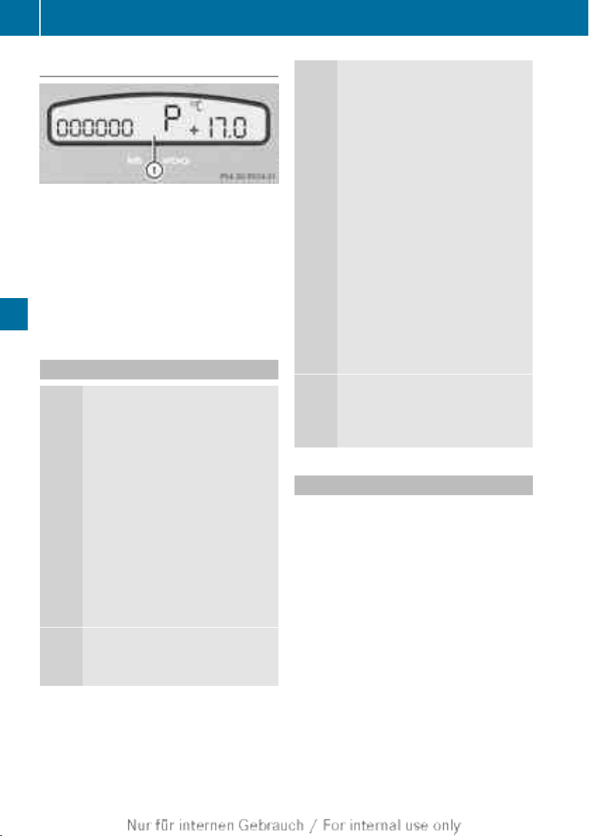
Automatic transmission
92
Transmission position display
:
Transmission position/shift range
Current shift range : is shown in the instrument cluster display.
When the selector lever is in position D, you
can influence the gearshifts made by the
automatic transmission by:
Driving and parking
R
restricting the shift range
R
changing gear yourself
Transmission positions
B
Park position
This prevents the vehicle from rolling away when stopped. Do not
shift the transmission into position
P(Y page 91) unless the vehicle is
stationary.
i
The key can only be removed if
the transmission is in position P.
When there is no key in the ignition lock, the selector lever is
locked in position P.
Have the vehicle electronics
checked immediately at a qualified
specialist workshop.
C
Reverse gear
Only shift the transmission to R
when the vehicle is stationary.
A
Neutral
No power is transmitted from the
engine to the drive wheels.
Releasing the brakes will allow you
to move the vehicle freely, e.g. to
push it or tow it.
Do not shift the transmission to N
while driving. Otherwise, the automatic transmission could be damaged.
Shift into N briefly, if:
R
there is a risk of the vehicle skidding, e.g. on slippery roads in
winter.
R
you want to engage the transfer
case.
!
Rolling in neutral N can lead to
damage to the transmission.
7
Drive
The automatic transmission
changes gear automatically. All
forward gears are available.
Changing gear
The automatic transmission shifts to the individual gears automatically when it is in transmission position D. Gearshifting is determined by:
R
a shift range restriction, if selected
R
the position of the transfer case (HIGH or
LOW)
R
the position of the accelerator pedal
R
the road speed

Automatic transmission
93
Driving tips
Accelerator pedal position
Your style of driving influences how the automatic transmission shifts gear:
R
little throttle: early upshifts
R
more throttle: late upshifts
Kickdown
Use kickdown for maximum acceleration:
X
Depress the accelerator pedal beyond the
pressure point.
The transmission shifts to a lower gear
depending on the engine speed.
X
Ease off the accelerator pedal once the
desired speed is reached.
The automatic transmission shifts back up.
Towing a trailer
X
Drive in the middle of the engine speed
range on uphill gradients.
X
Shift down to shift range 3 or 2 depending
on the uphill or downhill gradient
(Y page 93).
X
Shift the transfer case into off-road driving
position LOW on extreme uphill gradients
or steep downhill gradients (Y page 110).
Shift ranges
Introduction
When the automatic transmission is in position D, it is possible to restrict or derestrict
the shift range.
The shift range selected is shown in the display.
Driving situations
=
To use the engine's braking effect
5
The braking effect of the engine can
be utilised on downhill gradients or
when driving:
R
on steep mountain roads
R
in mountainous terrain
R
in arduous conditions
4
The braking effect of the engine can
be utilised on extremely steep
downhill gradients and long downhill stretches.
Restricting the shift range
X
Press the selector lever to the left towards
D–.
The automatic transmission shifts down
one gear and restricts the shift range to the
relevant gear.
i
If the engine exceeds the maximum
engine speed when shifting down, the automatic transmission protects against engine
damage by not shifting down.
i
If the maximum engine speed for the shift
range is reached and you continue to accelerate, the automatic transmission shifts up
in order to prevent the engine from overrevving, even if the shift range is restricted.
Extending the shift range
X
Press the selector lever to the right towards
D+.
The automatic transmission shifts up one
gear and restricts the shift range to the relevant gear.
Driving and parking
Z

Automatic transmission
94
Clearing the shift range restriction
X
Press and hold the selector lever towards
D+ until D is shown once more in the multifunction display.
The automatic transmission shifts from the
current shift range directly to D.
Selecting the ideal shift range
X
Press the selector lever to the left towards
D– and hold it in position.
The automatic transmission shifts to the
gear which allows optimum acceleration
and deceleration. To do this, the automatic
Driving and parking
transmission shifts down one or more
gears.
i
The automatic transmission cannot shift
down beyond second gear. To shift to first
gear, you have to pull the left steering
wheel gearshift paddle.

Automatic transmission
Problems with the automatic transmission
Problem Possible causes/consequences and M Solutions
95
The transmission has
problems shifting gear.
The transmission is losing oil.
X
Have the transmission checked at a qualified specialist workshop immediately.
The acceleration ability
is deteriorating.
The transmission no
longer changes gear.
The transmission is in emergency mode.
It is only possible to shift into second gear and reverse gear.
X
Stop.
X
Shift the transmission to position P.
X
Turn the key to position 0 in the ignition lock.
X
Wait at least ten seconds before restarting the engine.
X
Shift the transmission to position D or R.
If D is selected, the transmission shifts into second gear; if R is
selected, the transmission shifts into reverse gear.
X
Have the transmission checked at a qualified specialist workshop immediately.
You hear a warning
tone.
You have:
R
switched off the engine
R
opened the driver's door
R
not moved the selector lever to position P
X
Move the selector lever to P.
Releasing the parking lock manually
If a fault occurs, you can release the selector
lever lock manually to move it out of position
P to, for example, tow the vehicle.
X
Apply the parking brake.
X
Press marking : down to the stop and
hold.
The selector lever can now be moved freely
until it is returned to position P.
Driving and parking
ADR (working speed governor)
ADR prevents a reduction in engine speed,
e.g. when the alternator is under high load.
The switches are located on the centre console.
Z

Refuelling
96
:
To activate ADR
;
To increase the engine speed
=
To lower the engine speed
Driving and parking
X
Make sure that the vehicle is stationary.
X
Move the selector lever to P(Y page 92).
X
Press the upper half of switch :.
ADR is activated. The engine idling speed
is controlled automatically. The K indicator lamp in the instrument panel lights
up.
If ADR is activated you can increase to a maximum of 1800 rpm or lower to a minimum of
900 rpm as necessary.
X
To increase the engine speed: press the
upper half of switch ;.
X
To lower the engine speed: press the
lower half of switch =.
Refuelling
Important safety notes
WARNING
G
Fuel is highly flammable. If you handle fuel
incorrectly, there is a risk of fire and explosion.
You must avoid fire, naked flames, creating
sparks and smoking. Switch off the engine
and, if applicable, the auxiliary heating before
refuelling.
WARNING
G
Fuels are poisonous and hazardous to health.
There is a danger of injury.
Do not swallow fuel or let it come into contact
with skin, eyes or clothing. Do not inhale fuel
vapours. Keep fuels out of the reach of children.
If you or others come into contact with fuel,
observe the following:
R
Wash the fuel off any affected areas of skin
with water and soap immediately.
R
If you get fuel in your eyes, rinse them thoroughly with clean water immediately. Seek
immediate medical attention.
R
If fuel is swallowed, seek immediate medical attention. Do not induce vomiting.
R
Change any clothing that has come into
contact with fuel immediately.
WARNING
G
If you mix diesel fuel with petrol, the flash
point of this fuel mixture is lower than that of
pure diesel fuel. When the engine is running,
components in the exhaust system may overheat unnoticed. There is a risk of fire.
Never refuel with petrol. Never add petrol to
diesel fuel.
!
Do not use petrol to refuel vehicles with a
diesel engine. Never mix diesel with petrol.
Even small amounts of the wrong fuel result
in damage to the fuel injection system.
!
Do not switch on the ignition if you accidentally refuel with the wrong fuel. Otherwise, the fuel will enter the fuel lines. Notify
a qualified specialist workshop and have
the fuel tank and fuel lines drained completely.
!
Overfilling the fuel tank could damage the
fuel system.
!
Take care not to spill any fuel on painted
surfaces. You could otherwise damage the
paintwork.

!
Use a filter when adding fuel from a fuel
can. The fuel lines and/or the diesel injection system could otherwise be blocked by
particles from the fuel can.
Further information on fuel and fuel quality
(Y page 191)
Preheater block
!
Do not close the bonnet. Otherwise, you
may damage the connection cable and a
resulting short circuit may damage the
engine electrical system. Lower the bonnet
without closing it and secure the cable to
prevent it from becoming crushed.
Refuelling
X
Insert connection cable = with plug ?
into power socket ;.
X
Connect the vehicle to a
230 V power supply using connection cable
=.
The preheater block is switched on. The
engine is maintained at operating temperature.
X
Carefully lower the bonnet.
97
Driving and parking
The preheater block makes it possible to keep
the engine at operating temperature at outside temperatures of down to -40†. The
engine is heated electrically. Power is supplied by a power cable connected to a
230 V power supply.
The preheater block's power socket is in the
engine compartment on the right when
viewed in the direction of travel.
X
Open the bonnet (Y page 140).
X
Open cover : in the direction of the arrow.
Z

98
Refuelling
Refuelling
Vehicles with a fuel filler flap
Example: station wagon
Driving and parking
Example: fuel filler flap
:
Fuel filler flap
;
Fuel filler cap
=
Tyre pressure table
X
Press fuel filler flap : in the direction of
the arrow.
The fuel filler flap opens slightly.
X
Open the fuel filler flap.
Vehicles without a fuel filler flap
Example: chassis cab/platform truck
Example: 6x6 chassis cab with crewcab
;
Fuel tank cap
?
Additional fuel tank cap
Opening the fuel filler cap
i
Chassis-cab/platform truck: a table
with the tyre pressures can be found in the
"Wheels and tyres" section (Y page 184).
Example: fuel filler cap
X
Turn lock cover B to the side.
X
Turn key A in fuel filler cap ; anti-clockwise and remove fuel filler cap ;.
 Loading...