

Page 1
É4635843904}ËÍ
4635843904
G-Class
Operator's Manual
Orderno. P4630121 13 Partno. 463 584 39 04 EditionA2017
G-ClassOperator'sManual
Page 2

Symbols
Registered trademarks:
R
Bluetooth®is aregistered trademark of Bluetooth SIG Inc.
R
DTS™ is aregistered trademark of DTS, Inc.
R
Dolby®and MLP™ are registered trademarks
of DOLBYLaboratories.
R
BabySmart™, ESP®and PRE-SAFE®are registered trademarks of Daimler AG.
R
HomeLink®is aregistered trademark of Johnson Controls.
R
iPod®and iTunes®are registered trademarks
of Apple Inc.
R
Logic7®is aregistered trademark of Harman
International Industries.
R
Microsoft®and Windows media®are registered trademarks of Microsoft Corporation.
R
SIRIUS®is aregistered trademark of Sirius
XM RadioInc.
R
HD Radio™ is aregistered trademark of iBiquity Digital Corporation.
R
Gracenote®is aregistered trademark of
Gracenote, Inc.
R
ZAGAT Survey®and related brands are registered trademarks of Zagat Survey, LLC.
In this Operator's Manual you will find the following symbols:
WARNING
G
Warning notes make you aware of dangers
which could pose athreat to your health or
life, or to the health and life of others.
instruction with several
steps.
This symbol tells you where
(Y
you can find more informa-
page)
tion about atopic.
This symbol indicates a
YY
warning or an instruction
that is continued on the next
page.
This text indicates ames-
Dis‐
sage on the multifunction
play
display/multimedia display.
Publication details
Internet
Further information about Mercedes-Benzvehicles and about Daimler AG can be found on the
following websites:
http://www.mbusa.com (USA only)
http://www.mercedes-benz.ca (Canada only)
Editorial office
Daimler AG: not to be reprinted, translated or
otherwise reproduced, in whole or in part, without written permission from Daimler AG.
Vehicle manufacturer
Daimler AG
Mercedesstrae 137
70327 Stuttgart
Germany
Environmental note
H
Environmental notes provide you with information on environmentally aware actions or
disposal.
Notes on material damage alert you to dan-
!
gers that could lead to damage to your vehicle.
Practical tips or further information that
i
could be helpful to you.
This symbol indicates an
X
instruction that must be followed.
Several of these symbols in
X
succession indicate an
As at 29.02.2016
Page 3
Welcome to the world of Mercedes-Benz
We urge you to read this Operator's Manual
carefully and familiarize yourself with the vehicle before driving. For yourown safety and a
longer vehiclelife,follow the instructions and
warning notices in this Operator's Manual.
Ignoring them couldresult in damage to the
vehicleorpersonal injury to you or others.
Vehicle damage caused by failure to follow
instructions is not covered by the MercedesBenz Limited Warranty.
The equipment or product designation of your
vehiclemay vary depending on:
R
Model
R
Order
R
Country specification
R
Availability
Mercedes-Benz therefore reservesthe right to
introduce changes in the following areas:
R
Design
R
Equipment
R
Technicalfeatures
The equipment in yourvehiclemay therefore
differfrom that showninthe descriptions and
illustrations.
The following are integralcomponents of the
vehicle:
R
DigitalOperator's Manual
R
Printed Operator's Manual
R
Maintenance Booklet
R
Equipment-dependent supplements
Keep these documents in the vehicleatall
times. If you sell the vehicle, alwayspassall
documents on to the new owner.
Your Operator's Manual:
Digital form inside the vehicle
The DigitalOperator's Manual provides
comprehensive and specifically adapted
information on yourvehicle's equipment
and multimediasystem. It contains informative animations, individuallanguage
settings and an intuitive search function.
Booklet inside the vehicle
In addition to this manualand the aforementioned digital media, you alsohave the
option to obtainacomprehensive printed
versionofthe Supplement for yourmultimediasystem from yourauthorized
Mercedes-Benz Center.
Digital form via the Internet
The Operator's Manual on the Internet provideseasy access to all information
regarding yourvehicleand multimediasystem. It alsoprovides helpful animations,
interesting background information and a
widearrayofsearch options.
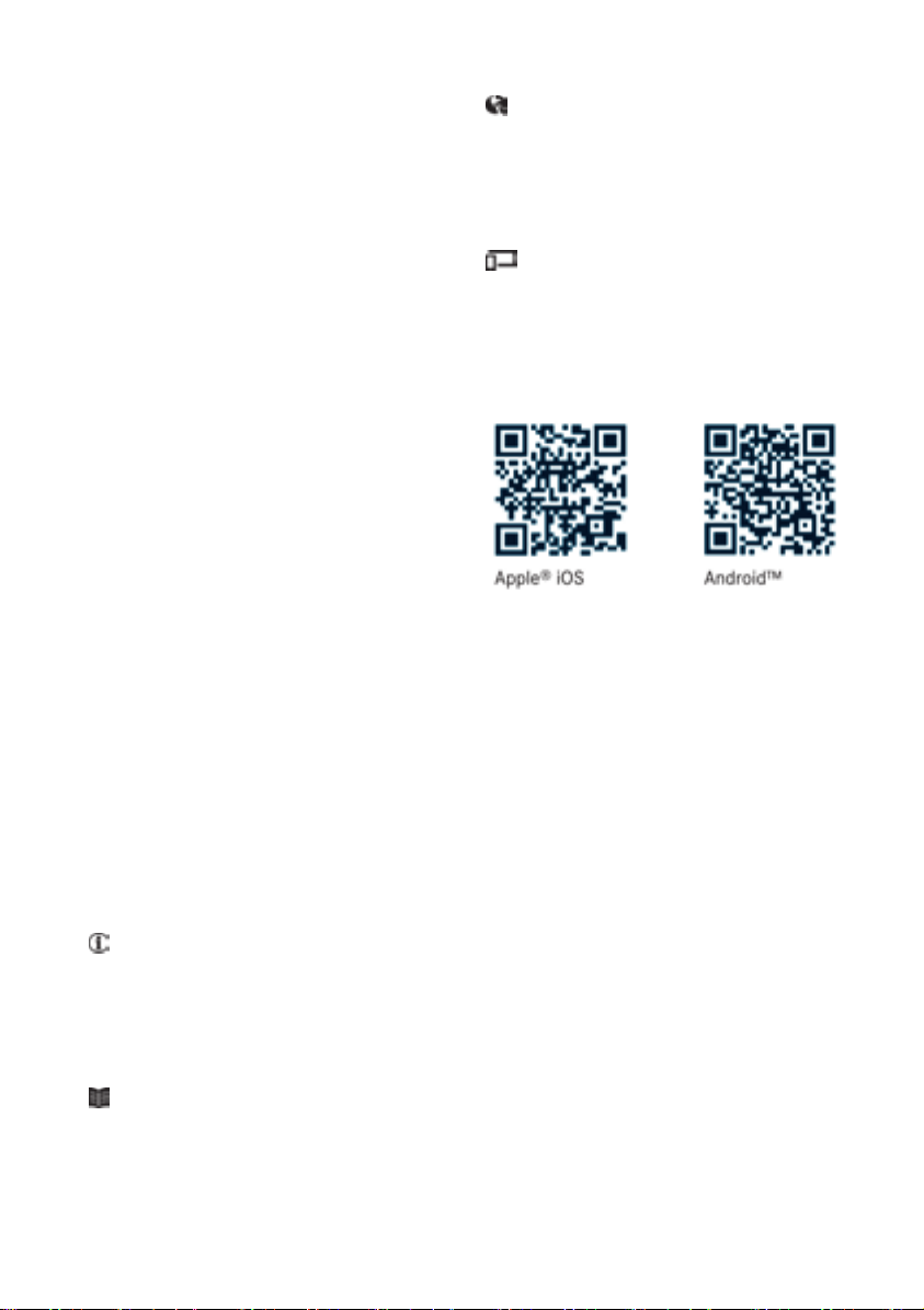
Digital form as an App
Using the Mercedes-Benz GuidesApp, you
can view all the information on yourvehicle
and multimediasystem via mobile Internet
or download it independently of network
access. Availablefor smartphones or tablets.
Please note that the Mercedes-Benz GuidesApp
may not yet be available in yourcountry.
Mercedes-Benz USA, LLC
Mercedes-Benz Canada,Inc.
ADaimler Company
4635843904
É4635843904}ËÍ
Page 4

2
Contents
Index ....................................................... 4
Digital Operator's Manual .................. 22
Introduction........................................... 22
Operation ............................................... 22
Introduction ......................................... 23
Protecting the environment ...................23
Genuine Mercedes-Benzparts............... 23
Operator's Manual ................................. 24
Service and vehicle operation ................24
Operating safety .................................... 26
QR codes for rescue cards .................... 28
Data stored in the vehicle ......................28
Information on copyright ....................... 29
At aglance ........................................... 31
Cockpit .................................................. 31
Instrument cluster .................................32
Multifunction steering wheel ................. 33
Center console ...................................... 34
Overhead control panel .........................36
Doorcontrolpanel ................................. 37
Safety ................................................... 38
Occupant safety .................................... 38
Childreninthe vehicle........................... 49
Pets in the vehicle................................. 57
Driving safety systems ........................... 57
Protection against theft .........................61
Lights and windshield wipers ............ 85
Exterior lighting ..................................... 85
Interior lighting ...................................... 88
Replacing bulbs..................................... 88
Windshield wipers .................................. 92
Climate control .................................... 95
Overview of the climate control sys-
tem ........................................................ 95
Operating the climate control system .... 97
Air vents .............................................. 101
Drivingand parking .......................... 103
Notesonbreaking-in anew vehicle..... 103
Driving ................................................. 103
Adjustable damping ............................. 109
Automatictransmission....................... 109
Refueling ............................................. 118
Parking ................................................ 120
Driving tips.......................................... 122
Driving systems ................................... 131
Off-road driving systems ...................... 145
Towing atrailer.................................... 149
On-board computer and displays .... 157
Important safety notes ........................ 157
Displays and operation ........................ 157
Menusand submenus ......................... 159
Displaymessages ............................... 169
Warning and indicator lamps in the
instrument cluster ............................... 187
Opening and closing ........................... 63
SmartKey ............................................... 63
Doors ..................................................... 66
Rear door ............................................... 68
Side windows ......................................... 69
Sliding sunroof ....................................... 71
Seats, steering wheel and mirrors .... 74
Correct driver's seat position ................74
Seats ..................................................... 74
Steering wheel ....................................... 79
Mirrors................................................... 81
Memory functions .................................. 83
Multimediasystem ........................... 198
Generalnotes ...................................... 198
Important safety notes ........................ 198
Function restrictions ............................ 198
Operating system ................................ 199
Stowageand features ...................... 204
Loading guidelines............................... 204
Stowageareas ..................................... 205
Features.............................................. 210
Page 5

Maintenance and care ...................... 225
Engine compartment ........................... 225
Maintenance ........................................ 230
Care ..................................................... 231
Breakdown assistance ..................... 238
Where willIfind...? .............................. 238
Flat tire ................................................ 240
Battery (vehicle) .................................. 241
Jump-starting ....................................... 243
Towing and tow-starting ...................... 246
Fuses ...................................................248
Wheels and tires ............................... 251
Important safety notes ........................ 251
Operation ............................................ 251
Winter operation.................................. 252
Tire pressure ....................................... 254
Loading the vehicle .............................. 260
All about wheels and tires ................... 263
Changing awheel ................................ 269
Wheeland tire combinations ...............273
Contents
3
Technical data ................................... 274
Information regarding technical data ... 274
Vehicle electronics .............................. 274
Identification plates .............................275
Service products and filling capaci-
ties ...................................................... 276
Vehicle data ......................................... 281
Vehicle data for off-roaddriving .......... 283
Trailer tow hitch ................................... 284
Page 6

Index
4
1, 2, 3...
4ETS (Electronic Traction System)
see ETS/4ETS (Electronic Traction System)
12 Vsocket
see Socket (12 V)
115 Vsocket ...................................... 213
A
ABS (Anti-lock Braking System)
Display message ............................ 171
Function/notes ................................ 57
Warninglamp ........................ 190,191
Accident
Automatic measures after an acci-
dent .................................................49
Activatingmedia mode
General notes................................203
ADAPTIVE BRAKE .................................61
Additives (engineoil) ........................ 279
Addressbook
see also Digital Operator's Man-
ual .................................................. 198
Adjustabledamping .......................... 109
Adjusting thevolume
COMAND .......................................199
Airbags
Deployment ..................................... 46
Display message ............................ 175
Front airbag (driver, front
passenger)....................................... 45
Important safety notes .................... 43
Introduction ..................................... 43
PASSENGER AIR BAG OFF indica-
tor lamp ...........................................39
Pelvis air bag ................................... 45
Side impact air bag .......................... 45
Window curtain air bag .................... 46
Air vents
Important safety notes .................. 101
Rear ..................
Set
ting ...........................................101
Setting the center airvents ........... 102
Setting the sideair vents ...............102
Air-conditioningsystem
see Climate control
............................. 102
Alarm
ATA (Anti-Theft Alarm system) ......... 61
Switching off (ATA) .......................... 61
Switching the function on/off
(ATA) ................................................ 61
Alarm system
see ATA (Anti-Theft Alarm system)
All-wheeldrive
Transfercase ................................. 145
AMG menu (on-board computer) ..... 167
Anti-theft alarm system
see ATA (Anti-Theft Alarm system)
Approach/departure angle .............. 130
Ashtray ............................................... 211
Assistancedisplay (on-board com-
puter) ..................................................164
Assistancemenu (on-board com-
puter) ..................................................164
ASSYST service interval display
Service messages .......................... 230
ATA (Anti-Theft Alarm system)
Activating/deactivating ................... 61
Function ...........................................61
Switching off the alarm .................... 61
Authorized Mercedes-Benz Center
see Qualifiedspecialist workshop
AUTO lights
Displaymessage ............................ 176
see Lights
Automatic car wash(care) ............... 231
Automatic engine start (ECO start/
stopfunction) .................................... 107
Automatic engine switch-off(ECO
start/stopfunction) .......................... 106
Automatic headlamp mode ................ 86
Automatic transmission
Displaymessage ............................ 186
Drive position (ECOstart/stop
function) ........................................ 111
Drive program................................ 114
Driving tips.................................... 112
Emergency running mode.............. 117
Engaging drive position .................. 111
Engaging neutral ............................ 111
Engaging reverse gear................... 110
park p
Engaging the
Important safety notes .................. 109
osition ............ 110
Page 7

Index
5
Kickdown ....................................... 112
Manualshifting .............................. 115
Neutral (ECO start/stop func-
tion) ............................................... 111
Overview ........................................ 109
Problem (malfunction) ................... 117
Programselector button ................ 113
Pulling away................................... 105
Selector lever ................................ 110
Shift ranges ................................... 114
Steering wheelpaddleshifters ...... 114
Trailer towing ................................. 113
Transmission position display ........ 110
Automatic transmission emer-
gencymode ....................................... 117
Axle load, permissible(trailertow-
ing) ...................................................... 284
B
BabySmart™
Air bagdeactivation system ............. 53
Back button ....................................... 199
Backup lamp
Replacing bulbs............................... 91
Ball coupling
Installing ........................................ 152
BAS (Brake Assist System) ................. 58
Battery (SmartKey)
Checking .......................................... 65
Important safety notes .................... 64
Replacing ......................................... 65
Battery (vehicle)
Charging ........................................ 243
Displaymessage ............................ 178
Important safety notes .................. 241
Jump starting ................................. 243
Overview ........................................ 241
Blind SpotAssist
Activating/deactivating ................. 164
Activating/deactivating (on-
board computer) ............................ 164
Displaymessage ............................ 181
Notes/function .............................. 137
Blootooth
®
Connecting adifferent mobile
phone ............................................ 203
Bluetooth
®
Searching for amobilephone ........ 202
see also Digital Operator's Man-
ual.................................................. 198
Telephony ...................................... 201
Brake fluid
Displaymessage ............................ 173
Notes............................................. 279
Brake fluid level ................................ 230
Brake forcedistribution
see EBD (electronicbrake force
distribution)
Brake lamp
Replacing bulbs............................... 91
Brake lamps
Displaymessage ............................ 176
Brakes
ABS .................................................. 57
BAS .................................................. 58
Brake fluid (notes) ......................... 279
Displaymessage ............................ 171
EBD .................................................. 61
High-performance brake system .... 125
HOLD function ............................... 139
Important safety notes .................. 123
Maintenance .................................. 124
Parking brake ................................ 121
Riding tips...................................... 123
Warning lamp ................................. 189
Breakdown
see Flattire
see Towing away
Brightness control(instrument
clusterlighting) ................................... 32
Brush guard ....................................... 221
Bulbs
Backuplamp.................................... 89
Brake lamp ...................................... 89
Rear fog lamp .................................. 89
Standing lamps (fro
Sta
nding lamps (rear) ...................... 89
nt) ..................... 89
Tail lamp .......................................... 89
Turn signallamp(front) .................... 89
Turn signallamp(rear) ..................... 89
see Replacing bulbs
Page 8

Index
6
C
California
Important noticefor retail cus-
tomersand lessees .......................... 24
Callingupamalfunction
see Display messages
Camera
see Rear view camera
Care
Car wash ........................................ 231
Carpets..........................................237
Chrome parts................................. 235
Display...........................................236
Exhaustpipe.................................. 235
Exterior lights ................................ 234
General notes ................................ 231
Interior ...........................................236
Matte finish ................................... 233
Paint .............................................. 233
Plastic trim ....................................236
Power washer ................................ 232
Rearview camera .......................... 235
Rooflining ...................................... 237
Seat belt........................................ 237
Seat cover ..................................... 236
Selector lever................................ 236
Sensors ......................................... 234
Steering wheel............................... 236
Trimpieces.................................... 236
Washing by hand ........................... 232
Wheels........................................... 233
Windows........................................ 234
Wiperblades.................................. 234
Woodentrim .................................. 236
Cargocompartmentcover
Important safety notes .................. 209
Installing/removing ....................... 209
Notes/howtouse ......................... 209
Opening and closing ...................... 209
Cargocompartmentenlargement
Important safety notes .................. 206
Cargotie downrings ......................... 209
CD
see also Digital Operator's Man-
ual.................................................. 198
CD player/CD changer (on-board
computer) .......................................... 162
rcons
Cente
Lower section .................................. 35
Overview .......................................... 34
Upper section .................................. 34
Central locking
Automaticlocking (on-board com-
puter) ............................................. 166
Locking/unlocking (SmartKey)........ 63
Changeofaddress .............................. 25
Changeofownership .......................... 25
Changingbulbs
Standing lamp (rear) ........................ 91
Changinggears .................................. 112
Child
Restraint system .............................. 50
Child seat
BabySmart™ airbag deactivation
system ............................................. 53
Forward-facing restraint system ...... 55
LATCH-type(ISOFIX) child seat
anchors ............................................ 51
On the front-passenger seat............ 54
Problem (malfunction) ..................... 55
Rearward-facing restraint system .... 54
Top Tether ....................................... 52
Child-proof locks
Important safety notes .................... 56
Rear doors ....................................... 56
Children
Specialseatbeltretractor ............... 50
Childreninthe vehicle
Important safety notes .................... 49
Chrome parts (cleaning instruc-
tions) .................................................. 235
Cigarette lighter ................................ 212
Cleaning
Mirror turn signal ........................... 234
Trailer tow hitch ............................. 235
Climate control
Controlling automatically................. 98
Cooling with airdehumidification ..... 97
Defrosting the windows................... 99
Defrosting the windshield ................ 99
Dual-zone automatic climate con-
trol ................................................... 95
ECO start/stop function .................. 97
Important safety notes .................... 95
ole
Page 9

Index
7
Indicator lamp .................................. 97
Maximumcooling .............................99
Notes on using dual-zone auto-
matic climate control ....................... 96
Overview of systems ........................ 95
Problemwith the rear window
defroster ........................................ 100
Problems with "cooling with air
dehumidification" .............................97
Refrigerant .....................................280
Refrigerant filling capacity ............. 281
Setting the airdistribution ...............98
Setting the airvents ...................... 101
Setting the airflow ........................... 98
Setting the temperature .................. 98
Switching air-recirculation mode
on/off............................................ 101
Switching on/off.............................. 97
Switching residualheaton/off...... 101
Switching the rearwindow
defroster on/off............................ 100
Switching the ZONE function
on/off.............................................. 99
Windshield defroster ........................ 99
Cockpit
Overview .......................................... 31
COMAND
Switching on/off........................... 199
see separate operating instructions
COMAND display
Cleaning ......................................... 236
Combination switch ............................ 87
Connecting aUSB device
see also Digital Operator's Man-
ual.................................................. 198
Consumptionstatistics (on-board
computer) .......................................... 160
Controller ........................................... 199
Controllingspeed
see DISTRONIC PLUS
Convenience closingfeature .............. 70
Convenience opening feature ............ 70
Coolant (engine)
Checking the level ......................... 229
Displaymessage ............................ 176
Filling capacity ............................... 280
Notes............................................. 279
Temperature (on-board com-
puter) ............................................. 167
Temperature gauge........................ 158
Warning la
ooling
C
see Climate control
Copyright ............................................. 29
Cruise control
Cruisecontrol lever ....................... 131
Deactivating ................................... 132
Driving system ............................... 131
Function/notes............................. 131
Generalnotes ................................ 131
Important safety notes .................. 131
Resuming the storedspeed ........... 132
Setting aspeed .............................. 132
Storing and maintaining current
speed ............................................. 131
Cup holder
Center console .............................. 210
Important safety notes .................. 210
Rear compartment ......................... 210
mp ................................. 194
D
Data
see Technical data
Daytime runninglamps
Displaymessage ............................ 176
Switching on/off(on-board com-
puter) ............................................. 165
Switching on/off(switch) ................ 85
Delayed switch-off
Exterior lighting (on-board com-
puter) ............................................. 165
Interior lighting .............................. 166
Diagnosticsconnection ...................... 27
Differential locks
Disengaging ................................... 149
Engaging ........................................ 148
Front axle...................................... 149
Generalnotes ................................ 147
Rear axle........................................ 149
Terrain........................................... 147
Transfercase................................. 149
Digital Operator's Manual
Help................................................. 22
Introduction ..................................... 22
Page 10

Index
8
Digital speedometer .........................160
Display messages
Calling up (on-board computer) ..... 170
Driving systems .............................179
Engine ............................................ 176
General notes ................................ 169
Hiding (on-board computer) ........... 170
Lights ............................................. 176
Safety systems .............................. 171
Service intervaldisplay.................. 230
SmartKey ....................................... 187
Tires ............................................... 183
Vehicle........................................... 186
Distance recorder
see Odometer
see Tripodometer
Distance warning(warning lamp) .... 196
DISTRONICPLUS
Activating ....................................... 134
Activation conditions ..................... 134
Cruise control lever ....................... 134
Deactivating ................................... 136
Displaymessage ............................ 181
Driving tips.................................... 136
Driving with DISTRONIC PLUS....... 135
Function/notes............................. 132
Important safety notes .................. 133
Stopping ........................................ 135
Warning lamp ................................. 196
Doors
Automaticlocking (on-board com-
puter) ............................................. 166
Automaticlocking (switch) ............... 67
Central locking/unlocking
(SmartKey)....................................... 63
Control panel ................................... 37
Displaymessage ............................ 186
Emergency locking ........................... 68
Emergency unlocking ....................... 68
Important safety notes .................... 66
Opening (frominside)...................... 67
Overview .......................................... 66
Drinking and driving ......................... 123
Drive program
Automatictransmission................. 114
Display........................................... 110
SETUP (on-board computer,
Mercedes-AMGvehicles) ............... 168
Driver's door
see Doors
Drivingdownhill ................................ 130
Drivinginmountainous terrain
Approach/departure angle ............ 130
Driving downhill............................. 130
Gradient-climbing capability
(maximum) ..................................... 130
Drivinglamps
nning lamps
see Day
Drivingoff-road
Driving downhill............................. 130
see Off-road driving
Drivingonfloodedroads .................. 125
Drivingsafety systems
ABS (Anti-lock Braking System) ....... 57
ADAPTIVEBRAKE............................. 61
BAS (Brake Assist System) .............. 58
EBD (electronicbrake force distri-
bution) ............................................. 61
ESP
gram) ............................................... 58
Important safety information ........... 57
Overview .......................................... 57
Drivingsystems
Blind Spot Assist ............................ 137
Cruise control ................................ 131
Displaymessage ............................ 179
DISTRONIC PLUS........................... 132
HOLD function ............................... 139
PARKTRONIC ................................. 140
Rear viewcamera .......................... 143
Drivingtips
Automatictransmission ................. 112
Brakes ........................................... 123
Break-in period.............................. 103
DISTRONIC PLUS........................... 136
Downhillgradient ........................... 123
Drinking and driving ....................... 123
Driving in winter ............................. 126
Driving on floodedroads ................ 125
Driving on sand .............................. 129
Driving on wetroads ...................... 125
Driving overobstacles ................... 129
Exhaustcheck ............................... 123
Fuel................................................ 122
General.......................................... 122
Gravel roads .................................. 129
time ru
®
(Electronic Stability Pro-
Page 11

Index
9
Hydroplaning ................................. 125
Icy roadsurfaces........................... 126
Important safety notes .................. 103
Limited braking efficiency on sal-
ted roads ....................................... 124
Off-roaddriving .............................. 127
Off-roadfording ............................. 126
Pulling away on slippery surfaces..125
Snow chains .................................. 253
Subjecting brakes to aload........... 124
The first 1500 km .......................... 103
Tire ruts ......................................... 129
Towing atrailer.............................. 151
Traveling uphill ............................... 130
Wet roadsurface ........................... 124
DVD audio
Operating (on-board computer) ..... 162
DVD video
Operating (on-board computer) ..... 162
see also Digital Operator's Man-
ual.................................................. 198
E
EASY-ENTRY feature
Activating/deactivating ................. 166
Function/notes................................ 80
EASY-EXIT feature
Function/notes................................ 80
Switching on/off........................... 166
EBD (electronicbrake forcedistribution)
Displaymessage ............................ 172
Function/notes................................ 61
ECOstart/stopfunction
Deactivating/activating ................. 106
Generalinformation ....................... 106
Electronic Stability Program
®
see ESP
(Electronic Stability Program)
Emergency
Automaticmeasures afteranacci-
dent ................................................. 49
Emergencyrelease
Driver's door.................................... 68
Vehicle............................................. 68
EmergencyTensioningDevices
Activation ......................................... 46
Emissionscontrol
Service and warranty information .... 24
Engine
Check Engine warning lamp ........... 194
Displaymessage ............................ 176
ECO start/stop function ................ 106
Engine number ............................... 276
Irregularrunning ............................ 108
Jump-starting ................................. 243
Starting problems .......................... 108
Starting the engine with the
SmartKey ....................................... 105
Switching off .................................. 121
Tow-starting (vehicle)..................... 248
Engine electronics
Problem (malfunction) ................... 108
Engine oil
Adding ........................................... 228
Additives ........................................ 279
Checking the oillevel ..................... 227
Checking the oillevel using the
dipstick .......................................... 227
Checking the oillevel using the
on-board computer........................ 227
Displaymessage ............................ 178
Filling capacity ............................... 279
Generalnotes ................................ 278
Notesabout oilgrades................... 278
Notesonoil level/consumption .... 227
Temperature (on-board com-
puter) ............................................. 167
Entering an address
see also Digital Operator's
al.................................................. 198
u
®
(ElectronicStability Pro-
ESP
Man-
gram)
AMG menu (on-board computer) ... 168
Characteristics ................................. 59
Deactivating/activating ................... 59
Displaymessage ............................ 171
Function/notes................................ 58
Generalnotes .................................. 58
Important safety information ........... 59
Trailer stabilization ........................... 60
Warning lamp ................................. 191
ETS/4ETS (ElectronicTraction Sys-
tem) ...................................................... 59
Page 12

10
Index
Exhaust
see Exhaust pipe
Exhaust check ...................................123
Exhaustpipe
Cleaning ......................................... 235
Exterior lighting
Cleaning ......................................... 234
see Lights
Exterior mirrors
Adjusting ......................................... 81
Dipping (automatic) ......................... 83
Folding in whenlocking (on-board
computer) ...................................... 167
Folding in/out(automatically)......... 82
Folding in/out (electrically) ............. 82
Outofposition (troubleshooting)..... 82
Setting ............................................. 82
Storing settings (memory func-
tion) ................................................. 83
Storing the parking position ............. 83
F
Favorites
Overview ........................................ 200
Filler cap
see Refueling
First-aidkit ......................................... 238
Flat tire
Changing awheel/mounting the
spare wheel................................... 269
Preparing the vehicle..................... 240
Folding the seat backrest(rear)
forwards/back .................................. 207
Frequencies
Mobilephone ................................. 274
Two-way radio ................................ 274
Fuel
Additives ........................................ 278
Consumption statistics .................. 160
Displaying the range...................... 160
Driving tips.................................... 122
Fuelgauge ....................................... 32
Grade (gasoline)............................ 277
Important safety notes .................. 277
Premium-grade unleadedgaso-
line ................................................. 277
Problem (malfunction) ................... 120
Refueling ........................................ 118
Tank content/reserve fuel............. 277
Fuelfillerflap
Closing ........................................... 119
Emergency release ........................ 119
Opening ......................................... 119
Fuellevel
Calling up the range(on-board
computer) ...................................... 160
Fueltank
Capacity ........................................ 277
Problem (malfunction) ................... 120
Fuseallocationchart ........................ 249
Fusebox
cargo compartment ....................... 250
Dashboard ..................................... 249
Front-passenger footwell ............... 249
Transmission tunnel....................... 250
Fuses
Allocation chart ............................. 249
Before changing ............................. 249
Dashboard fusebox ....................... 249
Fuseallocation chart ..................... 249
Fusebox in the cargocompart-
ment .............................................. 250
Fusebox in the front-passenger
footwell .......................................... 249
Fusebox in the transmission tun-
nel ................................................. 250
Important safety notes .................. 248
G
Garagedooropener
Clearing the memory ..................... 224
Generalnotes ................................ 221
Important safety notes .................. 222
Opening/closing the garagedoor..224
Problems whenprogramming ........224
Programming the remote control ... 222
Synchronizing the rolling code ....... 223
Gasoline ............................................. 277
Gear indicator (on-board com-
puter) ..................................................167
Genuine parts ...................................... 23
Glove box ...........................................205
Page 13

Index
11
Google™ Local Search
see alsoDigital Operator's Man-
ual.................................................. 198
GTW (Gross Trailer Weight) (defini-
tion) .................................................... 268
H
Hazard warning lamps ........................ 87
Head restraints
Adjusting .........................................76
Adjusting (rear)................................ 77
Installing/removing (rear)................ 77
Luxury.............................................. 76
Resetting (front) ............................... 76
see NECK-PROheadrestraints
see NECK-PROluxuryheadrestraints
Headlamps
Cleaning system (function) .............. 86
Cleaning system (notes) ................ 280
Fogging up ....................................... 87
Protective grille................................ 90
see Automatic headlamp mode
Heating
see Climate control
Highbeamflasher ............................... 87
High-beam headlamps
Display message ............................ 176
Switching on/off .............................. 87
HOLDfunction
Activating ....................................... 139
Activation conditions ..................... 139
Deactivating ................................... 139
Function/notes............................. 139
Generalnotes ................................ 139
Home address
see also Digital Operator's Man-
ual.................................................. 198
Hood
Closing ........................................... 226
Displaymessage ............................ 186
Important safety notes .................. 225
Opening ......................................... 225
Horn ...................................................... 31
Hydroplaning ..................................... 125
I
Ignitionlock
see Key positions
Immobilizer .......................................... 61
Indicator lamp
Replacing bulbs(rear) ...................... 91
Insect protection on the radiator .... 226
Instrument cluster
Overview .......................................... 32
Warning and indicator lamps ........... 32
Instrument clusterlighting .............. 157
Interior lighting
Automaticcontrol ............................ 88
Delayed switch-off (on-board
computer) ...................................... 166
Overview .......................................... 88
®
iPod
see also Digital Operator's Man-
ual.................................................. 198
J
Jack
Pump lever ..................................... 270
Storage location ............................ 238
Using ............................................. 270
Jump starting (engine) ...................... 243
K
Keypositions
SmartKey ....................................... 104
L
Lap time (RACETIMER) ...................... 168
LATCH-type (ISOFIX)child seat
anchors ................................................ 51
License plate lamp (display mes-
sage) ................................................... 176
Light sensor(display message) ....... 176
Lights
Activating/deactivating the inte-
riorlighting delayedswitch-off ....... 166
Automaticheadlamp mode.............. 86
Combination switch ......................... 87
Fogged up headlamps...................... 87
Generalnotes .................................. 85
Page 14

12
Index
Hazard warning lamps ..................... 87
High beamflasher ............................ 87
High-beamheadlamps ..................... 87
Light switch .....................................85
Low-beamheadlamps...................... 85
Parking lamps .................................. 86
Rear fog lamp .................................. 86
Standing lamps ................................ 86
Switching the daytime running
lamps on/off(on-board com-
puter) ............................................. 165
Switching the daytime running
lamps on/off(switch) ...................... 85
Switching the exteriorlighting
delayedswitch-off on/off(on-
board computer) ............................ 165
Switching the surround lighting
on/off(on-board computer) .......... 165
Turn signals..................................... 87
see Interior lighting
see Replacing bulbs
Load anchorage ................................. 208
Loadingguidelines ............................ 204
Locking
see Central locking
Locking (doors)
Automatic........................................ 67
Emergency locking ........................... 68
From inside (central locking but-
ton) .................................................. 67
Locking centrally
see Central locking
Locking verification signal (on-
board computer) ............................... 166
LOWRANGE off-road gear ................ 146
Low-beam headlamps
Displaymessage ............................ 176
Switching on/off.............................. 85
Lumbar support
Adjusting the 4-waylumbarsup-
port.................................................. 78
Luxury headrestraints ....................... 76
M
M+S tires ............................................ 253
Malfunctionmessage
see Displaymessages
Matte finish(cleaning instruc-
tions) .................................................. 233
mbrace
Call priority .................................... 218
Displaymessage ............................ 173
Downloading destinations
(COMAND) ..................................... 218
Downloading routes ....................... 221
Emergency call.............................. 215
Generalnotes ................................ 214
Geofencing ................................... 221
Info callbutton .............................. 217
Locating astolen vehicle............... 220
Remote fault diagnosis.................. 220
Remote vehiclelocking .................. 219
Roadside assistance button ........... 216
Search &Send ............................... 218
Self-test ......................................... 215
Speed alert .................................... 221
System .......................................... 215
Triggering the vehiclealarm ........... 221
Vehicleremote unlocking .............. 219
Mechanical key
Function/notes................................ 64
Generalnotes .................................. 64
Inserting .......................................... 64
Locking vehicle................................ 68
Removing ......................................... 64
Unlocking the driver'sdoor.............. 68
Memory card (audio) ......................... 162
Memory function ................................. 83
Mercedes-Benz Intelligent Drive
DISTRONIC PLUS........................... 132
Messagememory (on-board com-
puter) .................................................. 170
Messages
see Displaymessages
Mirrorturn signal
Cleaning ......................................... 234
Mirrors
Sun visor ........................................ 211
see Exterior mirrors
see Rear-viewmirror
Mobilephone
Connecting (Bluetooth
face).............................................. 201
®
inter-
Page 15

Index
13
Connecting another mobile
phone............................................203
Frequencies................................... 274
Installation..................................... 274
Menu (on-board computer) ............ 163
Transmissionoutput (maximum).... 274
Modifying the programming
(SmartKey) ...........................................64
Mountingwheels
Lowering the vehicle...................... 272
Mounting anew wheel................... 272
Preparing the vehicle.....................270
Raising the vehicle ......................... 270
Removing awheel .......................... 272
Securing the vehicle against roll-
ing away ........................................ 270
MP3
Operation ....................................... 162
see also DigitalOperator's Man-
ual..................................................198
see separate operating instructions
Multifunctiondisplay
Function/notes .............................159
Permanent display......................... 165
Multifunctionsteering wheel
Operating the on-board computer .. 158
Overview .......................................... 33
Music files
see also DigitalOperator's Man-
ual..................................................198
N
Navigation
Entering adestination .................... 200
Menu (on-board computer) ............ 161
see also DigitalOperator's Man-
ual..................................................198
see separate operating instructions
NECK-PRO head restraints
Operation ......................................... 48
Resetting triggered .......................... 48
NECK-PRO luxury head restraints
Important safety notes .................... 48
Operation ......................................... 48
Resetting whentriggered ................. 49
Notes on breaking-inanew vehi-
cle ....................................................... 103
O
Occupant safety
Air bags...........................................43
Automatic measures after an acci-
dent ................................................. 49
BabySmart™ airbag deactivation
system ............................................. 53
Childreninthe vehicle..................... 49
Important safety notes.................... 38
Introduction to the restraint sys-
tem .................................................. 38
PASSENGER AIR BAG indicator
lamps ............................................... 39
Pets in the vehicle........................... 57
Restraint system warning lamp ........ 38
Seatbelt.......................................... 39
Odometer ........................................... 160
Off-road
Differential locks ............................ 147
Off-road ABS .................................... 58
Off-road driving
Checklist afterdriving off-road ...... 129
Checklist before driving off-road .... 128
Driving on sand .............................. 129
Generalinformation ....................... 127
Important safety notes .................. 127
Traveling uphill ............................... 130
Off-road fording ................................. 126
Off-road system
Permanent all-wheeldrive ............. 139
Oil
see Engine oil
On-board computer
AMG menu ..................................... 167
Assistance menu ........................... 164
Audio menu ................................... 162
Convenience submenu .................. 166
Displaymessages .......................... 169
Factory settings submenu ............. 167
Important safety notes .................. 157
Instrument cluster submenu .......... 165
Lighting submenu .......................... 165
Menu overview .............................. 159
Message memory .......................... 170
Navigation menu ............................ 161
Operation ....................................... 158
RACETIMER ................................... 168
Page 16

14
Index
Service menu ................................. 164
Settingsmenu ............................... 164
Standard display ............................ 160
Telephone menu ............................ 163
Tripmenu ...................................... 160
TV operation .................................. 163
Vehiclesubmenu ........................... 166
Video DVD operation ..................... 162
Operatingsafety
Declaration of conformity ................ 26
Important safety notes .................... 26
Operatingsystem
see On-board computer
Operation
Digital Operator's Manual................ 22
Operator's Manual
Vehicleequipment ........................... 24
Outside temperature display ........... 157
Overhead controlpanel ...................... 36
Override feature
Rear sidewindows........................... 56
P
Paint code number ............................ 275
Paintwork (cleaning instructions) ... 233
Parking
Engaging park position .................. 110
Important safety notes .................. 120
Parking brake ................................ 121
Position of exteriormirror, front-
passenger side................................. 83
Rear viewcamera .......................... 143
Switching off the engine ................ 121
see PARKTRONIC
Parking aid
see Exterior mirrors
see PARKTRONIC
see Rear viewcamera
Parking brake
Applying ......................................... 121
Displaymessage ............................ 172
Emergency braking ........................ 121
Warning lamp ................................. 193
Parking lamps
Switching on/off.............................. 86
PARKTRONIC
Deactivating/activating ................. 142
Driving system ............................... 140
Function/notes............................. 140
Important safety notes .................. 140
Problem (malfunction) ................... 142
Range of the sensors ..................... 140
Trailer towing ................................. 142
Warning display ............................. 141
PASSENGER AIRBAG OFF
Indicatorlamp.................................. 39
Problems (malfunctions).................. 55
Permanent all-wheeldrive
Off-road system ............................. 139
Pets in the vehicle ............................... 57
Phone book
see also Digital Operator's Man-
ual.................................................. 198
Plastictrim (cleaning instruc-
tions) .................................................. 236
Powersupply(trailer) ....................... 156
Powerwashers .................................. 232
Program selectorbutton .................. 113
Protectionagainst theft
ATA (Anti-Theft Alarm system)......... 61
Immobilizer ...................................... 61
Protectionofthe environment
Generalnotes .................................. 23
Pulling away
Automatictransmission ................. 105
Generalnotes ................................ 105
Trailer ............................................ 105
Q
QR code
Mercedes-Benz GuideApp ................. 1
Rescuecard ..................................... 28
Qualified specialist workshop ........... 27
R
RACETIMER(on-board computer,
Mercedes-AMG vehicles) .................. 168
RACETIMER
Deleting alllaps............................. 169
Displaying and starting .................. 168
Displaying the intermediate time ... 168
Resetting the current lap............... 169
Starting anew lap.......................... 168
Page 17

Index
15
Stopping ........................................ 168
Radiatorcover ................................... 226
Radio
Selecting astation ......................... 162
Radio mode
see also Digital Operator's Man-
ual.................................................. 198
Radio-wave reception/transmission in the vehicle
Declaration of conformity ................ 26
Rear benchseat
Folding forward .............................. 208
Rear compartment
Setting the airvents ...................... 102
Rear door
Closing ............................................. 69
Displaymessage ............................ 186
Important safety notes .................... 68
Opening ........................................... 68
Rear fog lamp
Displaymessage ............................ 176
Replacing bulbs............................... 91
Switching on/off.............................. 86
Rear seat bench
Folding into an upright position ..... 208
Rear viewcamera
Cleaning instructions ..................... 235
Displayinthe multimediasystem .. 143
Function/notes............................. 143
Generalnotes ................................ 143
Switching on/off........................... 143
Rear windowdefroster
Problem (malfunction) ................... 100
Switching on/off........................... 100
Rear windowwiper
Replacing the wiperblade ................ 93
Switching on/off.............................. 93
Rear-viewmirror
Dipping (automatic) ......................... 83
Refrigerant (air-conditioning system)
Important safety notes .................. 280
Refueling
Fuelgauge ....................................... 32
Important safety notes .................. 118
Refueling process .......................... 118
see Fuel
Remote control
Programming (garage door
opener) .......................................... 222
Replacing bulbs
Backuplamp.................................... 91
Brake lamp ...................................... 91
Important safety notes .................... 88
Overview of bulb types .................... 89
Rear fog lamp .................................. 91
Tail lamp .......................................... 91
Turn signal (rear) .............................. 91
Turn signals (front) ........................... 90
Reporting safety defects .................... 27
Rescue card
Re
serve (fuel tank)
see Fuel
Reserve fuel
Displaymessage ............................ 179
Warning lamp ................................. 194
Residual heat
Switching on/off........................... 101
Restraintsystem
Displaymessage ............................ 173
Introduction ..................................... 38
Warning lamp ................................. 193
Warning lamp (function) ................... 38
Reversinglamps (display mes-
sage) ................................................... 176
Roadside Assistance (breakdown) .... 25
Roofliningand carpets (cleaning
guidelines) ......................................... 237
Route (navigation)
see Route guidance (navigation)
Route guidance
see also Digital Operator's Man-
ual.................................................. 198
Route guidance(navigation) ............ 161
......................................... 28
S
Safety
Childreninthe vehicle..................... 49
see Occupant safety
Safety system
see Driving safety systems
SD card
Inserting ........................................ 203
Inserting/removing ........................ 203
Page 18

16
Index
Removing....................................... 203
SD memory card
seealsoDigitalOperator's Man-
ual..................................................198
Search&Send
see also DigitalOperator's Man-
ual..................................................198
Seat backrest
Folding back .................................. 207
Seat belts
Adjusting the height ......................... 41
center rear-compartment seat......... 42
Cleaning ......................................... 237
Correct usage.................................. 41
Fastening ......................................... 41
Important safety guidelines............. 40
Introduction ..................................... 39
Releasing ......................................... 43
Warning lamp ................................. 188
Warning lamp (function) ................... 43
Seat heating
Indicatorlamp(malfunction) ............ 79
Seat ventilation
Indicatorlamp(malfunction) ............ 79
Seats
Adjusting (electrically) ..................... 76
Adjusting the 4-waylumbarsup-
port.................................................. 78
Adjusting the headrestraint ............ 76
Cleaning the cover......................... 236
Correct driver'sseatposition ........... 74
Important safety notes .................... 74
Overview .......................................... 74
Storing settings (memory func-
tion) ................................................. 83
Switching seatheating on/off......... 78
Switching seatventilation on/off.... 79
Selectorlever
Cleaning ......................................... 236
Sensors (cleaning instructions) ....... 234
Serviceintervaldisplay
Displaying aservice message (on-
board computer) ............................ 231
Servicemenu(on-board com-
puter) .................................................. 164
Serviceproducts
Brake fluid ..................................... 279
Coolant (engine) ............................ 279
Engine oil....................................... 278
Fuel................................................ 276
Important safety notes .................. 276
Notes............................................. 276
s-
Refrigerant (air-conditioni
tem) ............................................... 280
Washerfluid ................................... 280
Setting the air distribution ................. 98
Setting the date/time format
see also Digital Operator's Man-
ual.................................................. 198
Setting the language
see also Digital Operator's Man-
ual.................................................. 198
Setting the time
see also Digital Operator's Man-
ual.................................................. 198
Settings
Calling up astoredsetting ............... 84
Factory (on-board computer) ......... 167
On-board computer....................... 164
SETUP (on-board computer,
Mercedes-AMG vehicles) .................. 168
Shift ranges ....................................... 114
Side impactair bag ............................. 45
Side marker lamp (display mes-
sage) ................................................... 176
Side windows
Convenience closing feature ............ 70
Convenience opening feature .......... 70
Important safety information ........... 69
Opening/closing .............................. 69
Overview .......................................... 69
Problem (malfunction) ..................... 70
SIRIUSservices
see also Digital Operator's Man-
ual.................................................. 198
Sliding sunroof
Important safety notes .................... 71
Opening/closing .............................. 72
Operating manually .......................... 72
Problem (malfunction) ..................... 73
SmartKey
Changing the battery ....................... 65
Changing the programming ............. 64
Checking the battery ....................... 65
Convenience closing feature ............ 70
ng sy
Page 19

Index
17
Convenience opening feature .......... 70
Display message ............................ 187
Door central locking/unlocking .......63
Important safety notes .................... 63
Loss .................................................66
Mechanical key ................................ 64
Overview .......................................... 63
Positions (ignition lock) ................. 104
Problem (malfunction) ..................... 66
Starting the engine ........................ 105
SMS
see also Digital Operator's Man-
ual .................................................. 198
Snow chains ...................................... 253
Socket (12 V)
Cargo compartment....................... 213
Front-passenger footwell ............... 212
General notes ................................ 212
Rear compartment.........................213
Sound
Switching on/off ........................... 199
Spare fuses ........................................ 249
Spare wheel
Spare wheel bracket at the rear .... 239
Stainless-steel spare hub cap ........239
Special seat beltretractor .................. 50
Specialist workshop ............................ 27
Speedometer
Digital............................................ 160
In the Instrument cluster ................. 32
Segments ...................................... 157
Selecting the displayunit ...............165
Standinglamps
Display message ............................ 176
Switching on/off .............................. 86
Starting the engine
Important safety notes .................. 104
Steering (display message) .............. 187
Steering wheel
Adjusting (electrically)..................... 80
Buttons (on-board computer) ......... 158
Cleaning .....................
Important sa
Paddle shifters ............................... 114
Steering wheel heating .................... 80
Storing settings (memory func-
tion) ................................................. 83
fety notes .................... 79
.................... 236
Steering wheel heating
Indicator lamp (malfunction) ............ 80
Steering wheel paddle shifters ........114
Stopwatch (RACETIMER) ................... 168
Stowage areas ................................... 205
Stowage compartment
Door stowage compartment .......... 206
Stowage compartments
Armrest (under) .............................206
Cupholders ................................... 210
Glove box ....................................... 205
Important safety information ......... 205
Stowagenet ................................... 206
Stowagepockets ........................... 206
Stowage net ....................................... 206
Summer opening
see Convenience opening feature
Summer tires
In winter ........................................ 253
Sun visor ............................................ 210
Surround lighting (on-board com-
puter) ..................................................165
SUV
(Sport Utility Vehicle) ....................... 26
Switchingair-recirculation mode
on/off ................................................. 101
Switchingonmedia mode
Via the device list.......................... 203
T
Tachometer ........................................ 157
Tail lamp
Replacing bulbs............................... 91
Tail lamps
Displaymessage ............................ 176
Tank content
Fuelgauge ....................................... 32
Technical data
Capacities ...................................... 276
Drawbarload(maximum) ............... 284
Information .................................... 274
Trailer loads................................... 284
Vehicledata................................... 281
Telephone
Accepting acall............................. 163
Authorizing amobilephone (con-
necting) ......................................... 202
Page 20

18
Index
Connecting amobile phone(gen-
eral information)............................201
Display message ............................ 187
Menu(on-board computer) ............ 163
Number from thephonebook ........ 163
Redialing........................................ 164
Rejecting/ending acall................. 163
see also Digital Operator's Man-
ual.................................................. 198
Switching between mobile
phones ........................................... 203
see Mobilephone
Temperature
Coolant .......................................... 158
Coolant (on-board computer) ......... 167
Engine oil(on-board computer) ...... 167
Outsidetemperature ...................... 157
Setting (climate control).................. 98
Tilt/slidingsunroof
see Sliding sunroof
Time
see separate operating instructions
Timing (RACETIMER) ......................... 168
Tire pressure
Calling up (on-board computer) ..... 257
Checking manually ........................ 257
Displaymessage ............................ 183
Maximum....................................... 256
Notes............................................. 255
Recommended ............................... 254
Tire pressure monitor
Checking the tire pressure elec-
tronically ........................................ 258
Function/notes............................. 257
Generalnotes ................................ 257
Important safety notes .................. 257
Radiotypeapproval for the tire
pressure monitor ........................... 260
Restarting ...................................... 259
Warning lamp ................................. 197
Warning message .......................... 259
Tires
Aspect ratio(definition) ................. 269
Average weight of the vehicle
occupants (definition) .................... 267
Bar (definition) ............................... 267
Changing awheel .......................... 269
Characteristics .............................. 267
Checking ........................................ 251
Curb weight (definition) ................. 268
Definition of
rectionofrotation ...................... 270
Di
Displaymessage ............................ 183
Distribution of the vehicleoccu-
pants (definition) ............................ 269
DOT (Department of Transporta-
tion) (definition) ............................. 267
DOT, Tire Identification Number
(TIN) ............................................... 266
GAWR(GrossAxle Weight Rating)
(definition) ..................................... 268
GTW(GrossTrailer Weight) (defi-
nition) ............................................ 268
GVW(GrossVehicleWeight) (def-
inition) ........................................... 268
GVWR (GrossVehicleWeight Rat-
ing)(definition) .............................. 268
Important safety notes .................. 251
Increased vehicleweightdue to
optionalequipment (definition) ...... 268
Information on driving .................... 251
Kilopascal(kPa)(definition) ........... 268
Labeling (overview) ........................ 264
Loadbearing index (definition) ...... 269
Loadindex ..................................... 266
Loadindex (definition) ................... 268
Maximumloadonatire (defini-
tion) ............................................... 268
Maximumloaded vehicleweight
(definition) ..................................... 268
Maximumpermissibletire pres-
sure (definition) ............................. 268
Maximumtire load ......................... 266
Maximumtire load (definition) ....... 268
Optionalequipment weight (defi-
nition) ............................................ 269
PSI (pounds persquare inch)(def-
inition) ........................................... 269
Replacing ....................................... 269
Service life ..................................... 252
Sidewall(definition) ....................... 269
Snow chains .................................. 253
Speed rating (definition) ................ 268
Storing ........................................... 270
Structure and characteristics
(definition) ..................................... 267
terms ......................... 267
Page 21

Index
19
Summer tiresinwinter .................. 253
Temperature .................................. 263
TIN (Tire Identification Number)
(definition) ..................................... 269
Tire bead (definition) ...................... 269
Tire pressure (definition) ................ 269
Tire pressures (recommended)...... 268
Tire size (data)............................... 273
Tire size designation, load-bearing
capacity, speed rating .................... 264
Tire tread....................................... 252
Tire tread(definition) ..................... 269
Totalloadlimit (definition) ............. 269
Traction......................................... 263
Traction(definition) ....................... 269
Tread wear ..................................... 263
TWR (permissibletrailerdrawbar
noseweight) (definition) ................. 269
Uniform Tire Quality Grading
Standards...................................... 263
Uniform Tire Quality Grading
Standards(definition) .................... 267
Wearindicator (definition) ............. 269
Wheel and tire combination ........... 273
Wheel rim (definition) .................... 268
see Flattire
Top Tether ............................................ 52
Tow-starting
Emergency engine starting ............ 248
Important safety notes .................. 246
Towingatrailer
Axle load,permissible.................... 284
Cleaning the trailertow hitch ......... 235
Coupling up atrailer...................... 154
Decoupling atrailer....................... 155
Driving tips.................................... 151
Important safety notes .................. 149
Installing the ball coupling ............. 152
Lights display message .................. 176
Pulling away with atrailer.............. 105
Shift range..................................... 113
Trailer loads................................... 284
Trailer tow hitch ............................. 284
Towingaway
Important safety guidelines........... 246
In the event of malfunctions .......... 248
s on the ground ....... 247
With both
axle
Towingeye
Front .............................................. 247
Rear ............................................... 247
Trafficreports
see also Digital Operator's Man-
ual.................................................. 198
Trailer
7-pinconnector............................. 156
Power supply ................................. 156
Trailer coupling
see Towing atrailer
Trailer loads
Technical data ............................... 284
Trailer loads and drawbar nose-
weights ............................................... 155
Trailer tow hitch
Ballposition ................................... 284
Trailer towing
®
................................................ 60
ESP
PARKTRONIC ................................. 142
Permissibletrailerloads and
drawbar noseweights ..................... 155
Transfer case
Generalnotes ................................ 145
Shift range..................................... 145
Shifting .......................................... 146
Shifting (general notes).................. 146
Shifting (important safety notes)... 146
Shifting to neutral .......................... 147
Switching off the off-road gear
ratio............................................... 146
Switching on the off-road gear
ratio............................................... 146
Transmission
see Automatictransmission
Transmissionpositions .................... 112
Transporting the vehicle .................. 247
Traveling uphill
Brow of hill ..................................... 130
Trim pieces(cleaning instruc-
tions) .................................................. 236
Trip computer (on-board com-
puter) .................................................. 160
Trip odometer
Calling up ....................................... 160
Resetting (on-board computer) ...... 160
Page 22

20
Index
Turn signals
Display message ............................ 176
Replacing bulbs(front) ..................... 90
Switching on/off .............................. 87
TV
Operating (on-boardcomputer) ..... 163
see Separate operating instructions
Two-way radio
Frequencies................................... 274
Installation ..................................... 274
Transmission output(maximum) .... 274
TWR (Tongue Weight Rating) (defi-
nition) ................................................. 269
Type identificationplate
see Vehicleidentificationplate
U
Unlocking
Emergency unlocking ....................... 68
From insidethe vehicle(central
unlocking button) ............................. 67
USBdevices
Connecting to the Media Inter-
face ...............................................203
V
Vanity mirror
Sun visor........................................ 211
Vehicle
Correct use ...................................... 27
Data acquisition ............................... 28
Display message ............................ 186
Equipment ....................................... 24
Individualsettings .......................... 164
Limited Warranty .............................28
Loading .......................................... 260
Locking (in an emergency) ............... 68
Locking (SmartKey) .......................... 63
Lowering ........................................ 272
Maintenance .................................... 25
Operation outsidethe USA/
Canada ............................................ 25
Parking .......................................... 120
Parking for along period................ 122
Pulling away................................... 105
Raising ........................................... 270
Securing from rolling away ............ 270
Tow-starting ................................... 248
Towing ........................................... 246
Transporting .................................. 247
Unlocking (inanemergency) ........... 68
Unlocking (SmartKey)...................... 63
Vehicledata................................... 281
Vehicledata ....................................... 281
Vehicledata (off-road driving)
Approach/departure angle ............ 283
Fording depth ................................ 283
Maximumgradient climbing abil-
ity .................................................. 283
Vehicledimensions ........................... 281
Vehicleemergencylocking ................ 68
Vehicleidentificationnumber
see VIN
Vehicleidentificationplate .............. 275
Vehicletoolkit .................................. 239
Ventilation
Setting the airflow ........................... 98
Video
Operating the DVD ......................... 162
see also Digital Operator's Man-
ual.................................................. 198
VIN
Type plate ...................................... 275
W
Warning and indicator lamps
ABS ................................................ 190
Brakes ........................................... 189
Check Engine ................................. 194
Coolant .......................................... 194
Distance warning ........................... 196
DISTRONIC PLUS........................... 196
®
.............................................. 191
ESP
®
ESP
OFF ....................................... 192
Fueltank ........................................ 194
Generalnotes ................................ 187
Overview .......................................... 32
Parking brake ................................ 193
PASSENGER AIR BAG OFF ............... 39
Reserve fuel................................... 194
Restraint system ............................ 193
Seatbelt........................................ 188
Tire pressure monitor .................... 197
Warning triangle ................................ 238
Page 23

Index
21
Warranty .............................................. 24
Washer fluid
Display message ............................ 187
Weather display (COMAND)
see alsoDigitalOperator's Man-
ual.................................................. 198
Wheel and tire combinations
Tires............................................... 273
Wheel bolttightening torque ........... 272
Wheels
Changing awheel .......................... 269
Checking ........................................ 251
Cleaning ......................................... 233
Important safety notes .................. 251
Informationondriving .................... 251
Interchanging/changing ................ 269
Mounting anew wheel ...................272
Mounting awheel .......................... 270
Removing awheel .......................... 272
Snow chains .................................. 253
Storing ...........................................270
Tightening torque........................... 272
Wheelsize/tire size ....................... 273
Windowcurtain air bag
Display message ............................ 174
Operation ......................................... 46
Windows
see Side windows
Windshield
Defrosting ........................................ 99
Windshieldheating .............................99
Windshield washerfluid
see Windshieldwasher system
Windshield washersystem
Adding washer fluid....................... 229
Notes............................................. 280
Windshieldwipers
Problem (malfunction) ..................... 94
Rear window wiper.......................... 93
Replacing the wiperblades.............. 93
Switching on/off.............................. 92
Winter driving
Important safety notes .................. 252
Slippery roadsurfaces ................... 126
Snow chains .................................. 253
Winter operation
Overview ........................................ 252
Radiatorcover............................... 226
Summer tires................................. 253
Winter tires
M+S tires....................................... 253
Wiperblades
Cleaning ......................................... 234
Important safety notes .................... 93
Replacing
Wo
oden trim (cleaning instruc-
tions) .................................................. 236
......................................... 93
Page 24
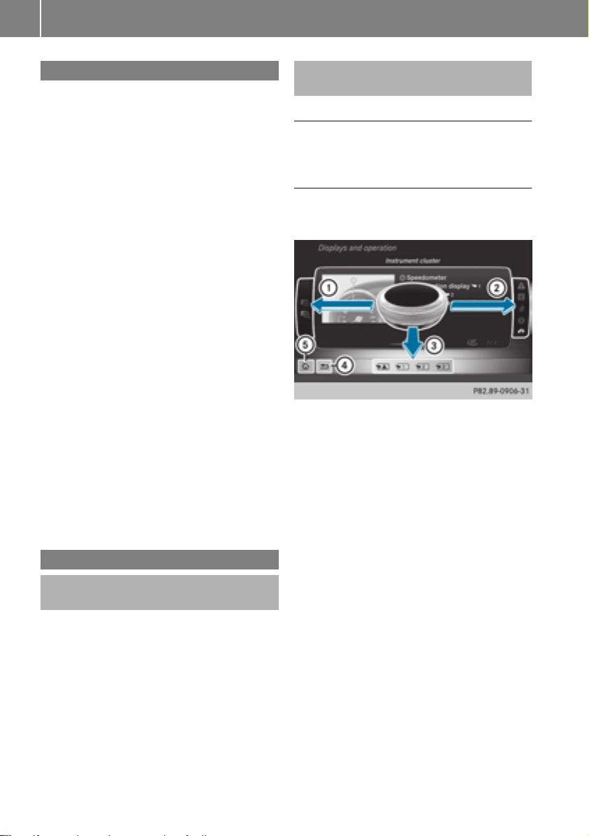
Digital Operator's Manual
22
Introduction
The printedOperator's Manual providesinformation about thesafeoperation of your vehicle.
The Digital Operator's Manual providescomprehensiveand specifically adapted information on
your vehicle's equipmentand multimedia system. You can call up theDigital Operator's Manual via themultimedia system.
You will notincur any costswhen calling up
i
theDigital Operator's Manual. The Digital
Operator's Manual works without connecting
to theInternet.
Thereare three ways to access thetopicsofthe
Digital Operator's Manual:
R
Visualsearch
The visual search allows you to exploreyour
vehicle"virtually". Starting from either the
vehicleexteriorvieworinteriorview, you can
access manyofthe differenttopicscovered
by theDigital Operator's Manual. To access
thevehicleinteriorsection,select the"Vehicle interior" view.
R
Keywordsearch
The keyword search allows you to search for a
keyword by enteringcharacters.
R
Contents
You can select individual sectionsinthe contents.
The Digital Operator's Manual is deactiva-
i
tedfor safetyreasonswhile driving.
Operation
Calling up theDigital Operator's Manual
X
Press the Ø buttononthe center console.
The overview relating to thevehicleappears.
X
Selectthe "Operator's Manual" menuitemby
turning 3 or pressing 7 thecontroller.
X
Confirm 7 themessage about thewarning
and safetynotes.
The basic menufor theDigital Operator's
Manual appears.
Operating theDigital Operator's Manual
General notes
Pleaseobservethe information about theoperation of thecontroller (
Y page 199).
Content pages
The contentpages can be accessed by meansof
avisual search,akeyword search or usingthe
contents.
X
To scroll forward/back: turn 3 thecon-
troller.
X
To displayinfull-screen or animation: slide
8 thecontroller to theleft :.
To select information textorsavebook-
X
marks: slide 9 thecontroller to the
right ;.
X
To select alink: slide 6 thecontroller
downwards =.
X
To exit acontent page: select the %
symbol ?.
To call up thebasic menuofthe Digital
X
Operator's Manual: select Þ symbol A.
To switch functions to themultimedia
X
system using thebuttonsonthe center
console: press the $, %, Õ or Ø
button.
The selected menuappears. The Digital Operator's Manual remainsopen in thebackground.
Page 25

Genuine Mercedes-Benz parts
23
Protecting the environment
General notes
Environmental note
H
Daimler's declared policy is one of comprehensive environmental protection.
The objectives are for the natural resources
that form the basis of our existence on this
planet to be used sparingly and in amanner
that takes the requirements of both nature
and humanity into account.
You too can help to protect the environment
by operating your vehicle in an environmentally responsible manner.
Fuel consumption and the rate of engine,
transmission, brake and tire wear are affected
by these factors:
R
operating conditionsofyour vehicle
R
your personal driving style
You can influence both factors. You should
bear the following in mind:
Operating conditions:
R
avoid short trips as these increase fuel consumption.
R
always make sure that the tire pressures
are correct.
R
do not carry any unnecessary weight.
R
remove roof racks once you no longer need
them.
R
aregularly serviced vehicle will contribute
to environmental protection. You should
therefore adhere to the service intervals.
R
always have service work carried out at a
qualified specialist workshop.
Personal driving style:
R
do not depress the accelerator pedal when
startingthe engine.
R
do not warm up the engine when the vehicle
is stationary.
R
drive carefully and maintain asafe distance
from the vehicle in front.
R
avoid frequent, sudden acceleration and
braking.
R
change gear in good time and use each gear
only up to Ô of its maximum engine speed.
R
switch off the engine in stationary traffic.
R
keep an eye on the vehicle's fuel consumption.
Environmental concerns and recommendations
Wherever the Operator's Manual requires you to
dispose of materials, first try to regenerate or reuse them. Observe the relevant environmental
rules and regulations when disposing of materials. In this way you will help to protect the environment.
Genuine Mercedes-Benz parts
Environmental note
H
Daimler AG also suppliesreconditioned major
assemblies and parts which are of the same
quality as new parts. They are covered by the
same Limited Warranty entitlements as new
parts.
Air bags and Emergency Tensioning Devi-
!
ces, as well as control units and sensors for
these restraint systems, may be installed in
the following areas of your vehicle:
R
doors
R
door pillars
R
door sills
R
seats
R
cockpit
R
instrumentcluster
R
center console
Do not install accessories such as audio systems in these areas. Do not carry out repairs
or welding. You could impair the operating
efficiency of the restraint systems.
Have aftermarket accessories installed at a
qualified specialist workshop.
You could jeopardize the operating safety of
your vehicle if you use parts, tires and wheels as
well as accessories relevant to safety which
have not been approved by Mercedes-Benz. This
could lead to malfunctionsinsafety-relevant
Introduction
Z
Page 26

Service and vehicleoperation
24
systems, e.g. the brake system. Use only genuine Mercedes-Benz parts or parts of equalquality. Only use tires, wheels and accessories that
have been specifically approved for your vehicle.
Genuine Mercedes-Benz parts are subject to
strict quality control. Every part has been specifically developed,manufactured or selected
for and adapted to Mercedes-Benz vehicles.
Therefore, only genuine Mercedes-Benz parts
Introduction
should be used.
More than 300,000 different genuine
Mercedes-Benz parts are available for
Mercedes-Benz models.
All authorized Mercedes-Benz Centers maintain
asupply of genuine Mercedes-Benz parts for
necessary service and repair work. In addition,
strategically located parts delivery centers provide quick and reliable parts service.
Always specify the vehicle identification number
(VIN) when ordering genuine Mercedes-Benz
Y page 275).
parts (
Operator's Manual
Vehicle equipment
This Operator's Manual describes all models
i
and all standard and optional equipment of
your vehicle available at the time of publication of the Operator's Manual.Country-specific differences are possible.Bear in mind
that your vehicle may not feature all functions
described here. This also applies to safetyrelevant systems and functions. The equipment in your vehicle may therefore differ from
that shown in the descriptions and illustrations.
The original purchase agreement lists all systems installed in your vehicle.
Should you have any questions concerning
equipment and operation, please consult an
authorized Mercedes-Benz Center.
The Operator's Manual and Maintenance Booklet are important documents and should be kept
in the vehicle.
Service and vehicleoperation
Warranty
The Limited Warranty for your vehicle applies in
accordance with the warranty terms and conditions in the Service and Warranty Information
booklet.
Your authorized Mercedes-Benz Center will
replace and repair all factory-installedparts in
accordance with the following warranty terms
and conditions:
R
New Vehicle Limited Warranty
R
Emission System Warranty
R
Emission Performance Warranty
R
California, Connecticut,Maine, Massachusetts, New York, Pennsylvania, Rhode Island
and Vermont Emission Control System Warranty
R
State warranty enforcementlaws (lemon
laws)
Replacement parts and accessories are covered
by the Mercedes-Benz Parts and Accessories
warranties. These are available at any authorized Mercedes-Benz Center.
Should you lose your Service and Warranty
i
Information booklet, have an authorized
Mercedes-Benz Center arrange for areplacement. The new Service and Warranty Information booklet will be posted to you.
Information for customers in California
Under California law you may be entitled to a
replacement of your vehicle or arefund of the
purchase price or lease price, if after areasonable number of repair attempts Mercedes-Benz
USA, LLC and/or its authorized repair or service
facilities fail to fix one or more substantial
defects or malfunctions in the vehicle that are
covered by its express warranty.
During the period of 18 months from original
delivery of the vehicle or the accumulation of
18,000 miles (approximately 29,000 km) on the
odometer of the vehicle, whichever occurs first,
areasonable number of repair attempts is presumed for aretail buyerorlessee if one or more
of the following occurs:
(1) the substantial defect or malfunction can
result in death or serious injuries for the
Page 27

Serviceand vehicleoperation
25
vehicleoccupants while driving and this
defect has already been repaired at least
twice and Mercedes-Benz, LLC has been
informed in writing of the necessity of a
repair.
(2) the defect or malfunction, though less seri-
ous than (1) above, has already been
repaired at least four times and MercedesBenz has been informed in writing of the
necessity of arepair.
(3) the vehiclecannot be used for longer than
30 calendar daysbecause of repair work
resulting from this or other substantial
defects or malfunctions.
Please send yourwritten notice to:
Mercedes-Benz USA, LLC
Customer Assistance Center
3MercedesDrive
Montvale,NJ07645-0350
Maintenance
Always bring the Maintenance Booklet with you
when taking the vehicletoanauthorized
Mercedes-Benz Center. Yourcustomer service
advisor willenter every service into yourMaintenance Booklet on yourbehalf.
Roadside Assistance
The Mercedes-Benz RoadsideAssistance Program offers technical help in the event of a
breakdown. Calls to the toll-free RoadsideAssistance Hotline are answered by our agents 24
hours aday,365 daysayear.
1-800-FOR-MERCedes(1-800-367-6372)
(USA)
1-800-387-0100(Canada)
For additionalinformation, refer to the
Mercedes-Benz RoadsideAssistance Program
brochure (USA) or the "Roadside Assistance"
section in the Service and Warranty Booklet
(Canada). You willfind both in the vehicledocument wallet.
Changeofaddress or changeofownership
In the event of achange of address, please send
us the "Notification of Address Change" in the
Service and Warranty Booklet or simplycall the
Mercedes-Benz Customer Assistance Center
(USA) at the hotline number
1-800-FOR-MERCedes (1-800-367-6372) or
Customer Service Center (Canada)at
1-800-387-0100.This willassist us in contacting you in atimely manner should the need arise.
If you sell yourMercedes, please leave all literature in the vehiclesothat it is available to the
next owner.
If you have purchased aused car, please send us
the "Notification of Used CarPurchase" in the
Service and Warranty Booklet or simplycall the
Mercedes-Benz Customer Assistance Center
(USA) at the hotline number
1-800-FOR-MERCedes (1-800-367-6372) or
Customer Service (Canada)at1-800-387-0100.
Vehicle operation outside the USA
and Canada
When you are abroad with yourvehicle, observe
the following points:
R
Service facilities or replacement parts may
not be readily available.
R
Lead-free fuel for vehicles with acatalytic
converter may not be available. Leaded fuel
can causedamage to the catalytic converter.
R
The fuel may have aconsiderably lower
octane number. Unsuitable fuel can cause
engine damage.
Some Mercedes-Benz modelsare available for
delivery in Europe through our European Delivery Program. For details, consult an authorized
Mercedes-Benz Center or write to one of the
following addresses.
In the USA
Mercedes-Benz USA, LLC
European Delivery Department
One MercedesDrive
Montvale,NJ07645-0350
In Canada
Mercedes-Benz Canada,Inc.
European Delivery Department
98 Vanderhoof Avenue
Toronto, Ontario M4G 4C9
Introduction
Z
Page 28

Operating safety
26
SportsUtility Vehicle
WARNING
G
Due to the high center of gravity, the vehicle
may start to skid and roll over in the event of
an abrupt steering maneuver and/or when
the vehicle's speed is not adapted to the road
conditions. There is arisk of an accident.
Always adapt your speed and driving style to
Introduction
the vehicle's driving characteristics and to the
prevailing road and weather conditions.
Utility vehicles have asignificantly higher rollover rate than other types of vehicles.
Failure to operate this vehicle safely may result
in an accident, rollover of the vehicle, and severe
or fatal injury.
In arollover crash, an unbelted person is significantly more likely to die than aperson wearing
aseat belt.
You and all vehicle occupants should always
wear your seat belts.
Operating safety
Important safety notes
WARNING
G
If you do not have the prescribed service/
maintenance work or any required repairs
carried out, this can result in malfunctionsor
system failures. There is arisk of an accident.
Always have the prescribed service/maintenance work as well as any required repairs
carried out at aqualified specialist workshop.
WARNING
G
Flammable material such as leaves, grass or
twigs may ignite if they come into contact with
hot parts of the exhaust system. There is arisk
of fire.
When driving off road or on unpaved roads,
check the vehicle's underside regularly.In
particular, remove parts of plants or other
flammable materials which have become
trapped. In the case of damage, contact a
qualified specialist workshop.
WARNING
G
Modifications to electronic components, their
software as well as wiring can impair their
function and/or the function of other networked components. In particular, systems
relevant to safety could also be affected. As a
result, these may no longer function as intended and/or jeopardize the operating safety of
the vehicle. There is an increased risk of an
accident and injury.
Never tamper with the wiring as well as electronic components or their software. You
should have all work to electrical and electronic equipment carried out at aqualified
specialist workshop.
There is arisk of damage to the vehicle if:
!
R
the vehicle becomes stuck,e.g. on ahigh
curb or an unpaved road
R
you drive too fast over an obstacle, e.g. a
curb, aspeed bump or apothole in the road
R
aheavy object strikes the underbody or
parts of the chassis
In situations like this, the body, the underbody, chassis parts, wheels or tires could be
damaged without the damage being visible.
Components damaged in this way can unexpectedly fail or, in the case of an accident, no
longer withstand the loads they are designed
to.
If the underbody paneling is damaged, combustible materials such as leaves, grass or
twigs can gather between the underbody and
the underbody paneling. If these materials
come in contact with hot parts of the exhaust
system, they can catch fire.
In such situations, have the vehicle checked
and repaired immediately at aqualified specialist workshop. If on continuing your journey you noticethat driving safety is impaired,
pull over and stop the vehicle immediately,
paying attention to road and traffic conditions. In such cases, consult aqualified specialist workshop.
Declaration of conformity for wireless
vehicle components
USA: "The wireless devices of this vehicle com-
ply with Part 15 of the FCC Rules. Operation is
Page 29

Operating safety
27
subject to the two following two conditions: 1)
These devices may not cause harmful interference, and 2) These devices must accept any
interference received, including interference
that may cause undesired operation. Changes
or modifications not expressly approved by the
party responsible for compliance could void the
user’s authority to operate the equipment."
Canada: "The wireless devices of this vehicle
comply with Industry Canada license-exempt
RSS standard(s). Operation is subject to the following two conditions: (1) These devices may
not cause interference, and (2) These devices
must accept any interference, including interference that may cause undesired operation of
the device."
Diagnostics connection
The diagnostics connection is only intended for
the connection of diagnostic equipment at a
qualified specialist workshop.
WARNING
G
If you connect equipment to adiagnostics
connection in the vehicle, it may affect the
operation of vehicle systems. As aresult, the
operating safety of the vehicle could be affected. There is arisk of an accident.
Only connect equipment to adiagnostics connection in the vehicle, which is approved for
your vehicle by Mercedes-Benz.
WARNING
G
Objects in the driver's footwell can restrict the
pedal travel or obstruct adepressed pedal.
The operating and road safety of the vehicle is
jeopardized. There is arisk of an accident.
Make sure that all objects in the vehicle are
stowed correctly, and that they cannot enter
the driver's footwell. Install the floormats
securely and as specified in order to ensure
sufficient clearance for the pedals. Do not use
loose floormats and do not place floormats on
top of one another.
If the engine is switched off and equipment
!
on the diagnostics connection is used, the
starter battery may discharge.
Connectingequipment to the diagnostics connection can lead to emissions monitoring information being reset, for example. This may lead
to the vehicle failing to meet the requirements of
the next emissions test during the main inspection.
Qualified specialist workshop
An authorized Mercedes-Benz Center is aqualified specialist workshop. It has the necessary
specialist knowledge, tools and qualifications to
correctly carry out the work required on your
vehicle. This is especially the case for work relevant to safety.
Observe the notes in the Maintenance Booklet.
Always have the following work carried out at an
authorized Mercedes-Benz Center:
R
work relevant to safety
R
service and maintenance work
R
repair work
R
alterations, installation work and modifications
R
work on electronic components
Correct use
If you remove any warning stickers, you or others could fail to recognize certain dangers.
Leave warning stickers in position.
Observe the following information when driving
your vehicle:
R
the safety notes in this manual
R
technical data for the vehicle
R
traffic rules and regulations
R
laws and safety standards pertaining to motor
vehicles
Reporting safety defects
USA only:
The following text is reproduced as required of
all manufacturers under Title 49, Code of U.S.
Federal Regulations, Part 575 pursuant to the
National Traffic and Motor Vehicle Safety Act of
1966.
If you believe that your vehicle has adefect
which could cause acrash or could cause injury
or death, you should immediately inform the
Introduction
Z
Page 30

Data stored in the vehicle
28
National HighwayTraffic Safety Administration
(NHTSA) in addition to notifying Mercedes-Benz
USA, LLC.
If NHTSA receives similarcomplaints, it may
open an investigation, and if it finds that asafety
defect exists in agroup of vehicles, it may order
arecall and remedy campaign. However, NHTSA
cannot become involved in individual problems
between you,yourdealer, or Mercedes-Benz
USA, LLC.
Introduction
To contact NHTSA, you may call the Vehicle
Safety Hotline toll-free at 1-888-327-4236
(TTY: 1-800-424-9153);goto http://
www.safercar.gov;orwrite to: Administrator,
NHTSA, 400 Seventh Street, SW., Washington,
DC 20590.
You can also obtain other information about
motor vehicle safety from
http://www.safercar.gov
Limited Warranty
Follow the instructions in this manual about
!
the proper operationofyourvehicle as well as
aboutpossible vehicle damage. Damage to
yourvehicle that arises from culpable contraventions against these instructions is not covered either by the Mercedes-Benz Limited
Warranty or by the New or Used-Vehicle Warranty.
QR codesfor rescue cards
The QR codes are secured in the fuel fillerflap
and on the opposite side on the B-pillar. In the
event of an accident, rescue services can use
the QR code to quickly find the appropriate rescue card for yourvehicle. The current rescue
card contains the most important information
aboutyourvehicle in acompact form, e.g. the
routing of the electric cables.
You can find more information under
www.mercedes-benz.de/qr-code.
Data stored in the vehicle
Data storage
Awide range of electronic components in your
vehicle contain data memories.
These data memories temporarilyorpermanently store technical information about:
R
the vehicle's operating state
R
incidents
R
malfunctions
In general, this technical information documents the state of acomponent, amodule, a
system or the surroundings.
These include, for example:
R
operating conditions of system components,
e.g. fluidlevels
R
the vehicle's status messagesand those of its
individual components, e.g. number of wheel
revolutions/speed, deceleration in movement, lateral acceleration, accelerator pedal
position
R
malfunctions and defects in important system
components, e.g. lights, brakes
R
vehicle reactions and operating conditions in
specialdriving situations, e.g. air bag deployment, intervention of stability control systems
R
ambient conditions, e.g. outside temperature
This data is of an exclusivelytechnical nature
and can be used to:
R
assist in recognizing and rectifying malfunctions and defects
R
analyze vehicle functions, e.g. after an accident
R
optimize vehicle functions
The data cannot be used to trace the vehicle's
movements.
When yourvehicle is serviced, technical information can be read from the event data memory
and malfunction data memory.
Services include, for example:
R
repairservices
R
service processes
R
warranties
R
quality assurance
The vehicle is read out by employees of the service network (including the manufacturer) using
specialdiagnostic testers. More detailed information is obtained from it, if required.
After amalfunction has been rectified, the information is deleted from the malfunction memory
or is continually overwritten.
When operating the vehicle, situations are conceivableinwhich this technical data, in connec-
Page 31

Informationoncopyright
29
tionwithotherinformation (ifnecessary,under
consultation with an authorizedexpert),could
be traced to aperson.
Examples include:
R
accident reports
R
damage to the vehicle
R
witnessstatements
Furtheradditional functions thathavebeencontractuallyagreeduponwiththe customerallow
certain vehicledatatobeconveyedbythe vehicle as well.The additional functions include, for
example, vehiclelocation in caseofanemergency.
COMAND/mbrace(Canada: TELEAID)
If the vehicleisequippedwithCOMAND or
mbrace,additional data aboutthe vehicle's
operation, the useofthe vehicleincertain situations, and the location of the vehiclemay be
compiled throughCOMAND or the mbrace system.
For additional information please refer to the
COMAND UserManualorthe DigitalOperator's
Manualand/or the mbrace Terms and Conditions.
Eventdata recorders
Thisvehicleisequippedwithanevent data
recorder(EDR). Thisvehicleisequippedwithan
event data recorder(EDR). The main purpose of
an EDR is to record, in certain crash or near
crash-like situations, such as an airbag deployment or hitting aroadobstacle,datathatwill
assist in understanding how avehicle'ssystems
performed. The EDR is designedtorecord data
relatedtovehicledynamics and safety systems
for ashort periodoftime, typically30seconds
or less.
The EDR in thisvehicleisdesignedtorecord
such data as:
R
How various systems in your vehiclewere
operating
R
Whether or not the driver and passenger
safety belts were buckled/fastened
R
How far(if at all) the driver wasdepressing the
accelerator and/or brake pedaland
R
How fast the vehiclewas traveling
Thesedatacan help provideabetter understanding of the circumstances in which crashes
and injuriesoccur. NOTE: EDR data arerecorded
by your vehicleonlyifanon-trivialcrash situationoccurs; no data arerecorded by the EDR
under normal drivingconditions and no personal
data (e.g. name, gender, ageand crash location)
rparti
arerecorded.However, othe
es, such as
lawenforcement could combine the EDR data
with the typeofpersonally identifying data routinely acquired duringacrash investigation.
Accesstothe vehicleand/or the EDR is needed
to readdatathatisrecorded by an EDR, and
special equipment is required.Inadditiontothe
vehiclemanufacturer,otherpartiesthathave
the special equipment, such as lawenforcement, can readthe information by accessing the
vehicleorthe EDR.
EDR data maybeusedincivil and criminal matters as atoolinaccident reconstruction, accident claimsand vehiclesafety.Since the Crash
Data RetrievalCDR toolthatisusedtoextract
data fromthe EDR is commerciallyavailable,
Mercedes-Benz USA, LLC ("MBUSA") expressly
disclaims any and allliability arising fromthe
extractionofthisinformation by unauthorized
Mercedes-Benz personnel.
MBUSA will not share EDR data with others
withoutthe consent of the vehicleowners or, if
the vehicleisleased, withoutthe consent of the
lessee. Exceptions to thisrepresentation
includeresponsestosubpoenas by lawenforcement; by federal, state or local government; in
connectionwithorarising outoflitigation inv
i
ng MBUSA or its subsidiariesand affiliates;or,
olv-
as required by law.
Warning: TheEDR is acomponent of the
Restraint System Module. Tamperingwith, altering,modifying or removing the EDR component
mayresultinamalfunctionofthe Restraint System Moduleand othersystems.
State laws or regulations regarding EDRs that
conflict with federalregulation arepre-empted.
This means thatinthe event of such conflict, the
federalregulation governs. As of February2013,
13 states have enacted laws relating to EDRs.
Informationoncopyright
Freeand open-source software
Informationonlicensefor freeand open-source
software used in your vehiclecan be found on
Introduction
Z
Page 32

Informationoncopyright
30
the data carrierinyourvehicledocument wallet
and,including updates,onthe following website:
http://www.mercedes-benz.com/opensource
Registeredtrademarks
Registered trademarks:
R
Introduction
Bluetooth®is aregisteredtrademark of Bluetooth SIG Inc.
R
DTS™ is aregisteredtrademark of DTS, Inc.
R
Dolby®and MLP™are registeredtrademarks
of DOLBY Laboratories.
R
BabySmart™, ESP®and PRE-SAFE®areregisteredtrademarks of Daimler AG.
R
HomeLink®is aregisteredtrademark of Johnson Controls.
R
iPod®and iTunes®areregisteredtrademarks
of Apple Inc.
R
Logic7®is aregisteredtrademark of Harman
InternationalIndustries.
R
Microsoft®and Windows media®areregisteredtrademarks of Microsoft Corporation.
R
SIRIUS®is aregisteredtrademark of Sirius
XM RadioInc.
R
HD Radio™ is aregisteredtrademark of iBiquity DigitalCorporation.
R
Gracenote®is aregisteredtrademark of
Gracenote,Inc.
R
ZAGAT Survey®and relatedbrands areregisteredtrademarks of ZagatSurvey,LLC.
Page 33

Cockpit
Cockpit
31
At aglance
Function Page
:
Combination switch 87
;
Steering wheel paddle shifters
=
Instrumentcluster 32
?
Horn
A
Overhead control panel 36
B
PARKTRONIC warning display
114
140
Function Page
C
Climatecontrol system 95
D
Ignition lock 104
E
Adjusts thesteering wheel 79
F
Cruisecontrol lever 131
G
Lightswitch 85
H
Opensthe hood 225
Page 34

Instrumentcluster
32
Instrumentcluster
At aglance
Function Page
:
Speedometer withsegments 157
Warning and indicator lamps:
÷ ESP
å ESP®OFF
! ABS
J Brakes(yellow)
L Low-beam headlamps
T Parking lamps
K High-beam headlamps
Brakes(red) 189
$ USAonly
J Canadaonly
Parking brake 193
F USAonly
J Canadaonly
· Distancewarning
;
#! Turn signals
=
Multifunction display 159
®
191
191
190
189
85
86
87
196
87
Function Page
?
Tachometer 157
Warning and indicator lamps:
R Rear fog lamp
; CheckEngine
h Tirepressuremonitor
6 Restraintsystem
ü Seat belts
A
Coolanttemperature gauge 158
Warning and indicator lamps:
? Coolant
B
Fuellevel indicator
Warning and indicator lamps:
8 Reserve fuel withfuel
filler flap location indicator
(right-hand side)
C
Instrumentclusterlighting 157
86
194
197
38
188
194
194
Page 35

Multifunction steering wheel
Multifunctionsteering wheel
33
At aglance
Function Page
:
Multifunction display 159
;
Multimediasystem display
= ?
Switches on the Voice Control System
? ~
Rejects or ends acall 163
Exits the telephone book/
redial memory
6
Makes or accepts acall
Switches to the redial mem-
ory
WX
Adjusts the volume
i Further information:
R
on the multimediasystem in the Digital
Operator's Manual
R
on the Voice Control System in the separate operating instructions
Function Page
8
Switchessound on/off
A
=;
Selects amenu 158
9:
Selects asubmenu or scrolls
through lists
a
Confirmsaselection 158
Hides display messages 170
B %
Back 158
Switches off the Voice Con-
trol System
158
Page 36

Center console
34
Center console
Center console, upper section
At aglance
Function Page
:
Multimedia system; see the
Digital Operator's Manual
;
c Seat heating
=
s Seat ventilation
?
c PARKTRONIC
A
è ECO start/stopfunction
78
79
140
106
Function Page
B
£ Hazard warning lamps
C
45PASSENGER AIRBAG OFF indicator lamp
D
å ESP
®
87
39
59
Page 37

Center console, lower section
Center console
35
At aglance
Function Page
E
Stowage compartment/
ashtray
F
Automatic transmission
selectorlever
G
Selectspark position 110
H
+ Activates/deactivates
theoff-road gear ratio
I
Stowage compartment 205
J
Stowage compartmentwith
Media Interface
K
Cigarettelighter 212
211
110
146
205
Function Page
L
Controller 199
M
Switches thewindshield
heating on/off
N
e Adjustable damping
O
Ú Selectsthe drivepro-
gram
Mercedes-AMGvehicles:
Ñ Selectsthe drivepro-
gram
P
Parking brake 121
99
109
113
113
Page 38

Overheadcontrol panel
36
Overheadcontrol panel
At aglance
Function Page
:
p Switches the left-hand
reading lamp on/off
;
c Switches the frontinterior lighting on
=
u Switches the rear interior lighting on/off
?
| Switches the frontinterior lighting/automatic interior lighting control off
A
p Switches the righthand reading lamp on/off
B
¡ Opens/closes the sliding sunroof
88
88
88
88
88
72
Function Page
C
ï Infocall button
(mbrace system)
D
Rear-view mirror 81
E
Buttons for the garage door
opener
F
F Breakdown assistance
call button (mbrace system)
G
G SOS button (mbrace
system)
H
Microphonefor mbrace system, telephoneand the Voice
Control System,see the separate operatinginstructions
217
224
216
215
Page 39

Door controlpanel
Door control panel
37
At aglance
Function Page
:
n Override feature forthe
rearsidewindows
;
W Opens/closes theside
windows
=
7Zö\
Adjustsand folds theexterior
mirrors in/out electrically
?
r 45=
Stores settings for the seat,
exterior mirrors and steering
column
56
69
81
83
Function Page
A
Adjusts the seats electrically 76
B
%&Locks/unlocks
the vehicle
C
Opens the door 67
67
Page 40

Occupant safety
38
Occupant safety
Introduction to the restraint system
The restraint system can reduce the risk of vehicle occupantscominginto contact with parts of
the vehicle's interior in the event of an accident.
The restraint system can also reduce the forces
to which vehicle occupantsare subjected during
an accident.
The restraint system comprises:
R
Seat belt system
Safety
R
Air bags
R
Child restraint system
R
Child seat securingsystems
The componentsofthe restraint system work in
conjunction with each other.They can only
deploy their protective function if, at all times, all
vehicle occupants:
R
have fastened their seat belts correctly
Y page 41)
(
R
have the seat and head restraint adjusted
properly (
As the driver, you also have to make sure that
the steering wheel is adjusted correctly.
Observe the information relating to the correct
driver's seat position (
You also have to make sure that an air bag can
inflate properly if deployed (
An air bag supplementsacorrectly worn seat
belt. As an additional safety device, the air bag
increases the level of protection for vehicle
occupantsinthe event of an accident. For example, if, in the event of an accident, the protection
offered by the seat belt is sufficient, the air bags
are not deployed. When an accidentoccurs,only
the air bags that increase protection in that particular accidentsituation are deployed. However, seat belts and air bags generally do not
protectagainst objects penetratingthe vehicle
from the outside.
Information on restraint system operation can
be found under "Triggering of the Emergency
Tensioning Devices and air bags" (
See "Children in the vehicle" for information on
children travelingwith you in the vehicle as well
as on child restraint systems (
Y page 74)
Y page 74).
Y page 43).
Y page 46).
Y page 49).
Important safetynotes
WARNING
G
Modifications to the restraint system may
cause it to no longer work as intended. The
restraint system may then not perform its
intended protective function and may fail in an
accidentortrigger unexpectedly, for example.
This poses an increased risk of injuryoreven
fatal injury.
Never modify parts of the restraint system.
Never tamper with the wiring, the electronic
componentsortheir software.
If it is necessary to modify componentsofthe
restraint system to accommodate aperson
with disabilities, contact an authorized
Mercedes-Benz Center for details. USA only:
for further information contact our Customer
Assistance Center at 1-800-FOR-MERCedes
(1‑800‑367‑6372).
Mercedes-Benz recommends that you only use
driving aids which have been approved specifically for your vehicle by Mercedes-Benz.
Restraint system warning lamp
The functionsofthe restraint system are
checked after the ignition is switched on and at
regular intervals while the engineisrunning.
Therefore, malfunctions can be detected in
good time.
The 6 restraint system warning lamp on the
instrument cluster lights up when the ignition is
switched on. It goes out no later than afew seconds after the vehicle is started. The components of the restraint system are in operational
readiness.
Amalfunction has occurred if the 6 restraint
system warning lamp:
R
does not light up after the ignition is switched
on
R
does not go out after afew seconds with the
enginerunning
R
lights up again while the engineisrunning
WARNING
G
If the restraint system is malfunctioning,
restraint system componentsmay be trig-
Page 41

Occupant safety
39
gered unintentionally or may not deploy as
intended during an accident.This can affect
for example the Emergency Tensioning
Device or the air bag. This poses an increased
risk of injury or even fatal injury.
Have the restraint system checked and
repaired in aqualified specialist workshop as
soon as possible.
PASSENGER AIR BAG OFF indicator
lamp
PASSENGER AIR BAG OFF indicator lamp : is
part of the BabySmart™ air bag deactivation
system.
Apermanently lit PASSENGER AIR BAG OFF
indicator lamp informs you that the frontpassenger front air bag is deactivated.
Depending on the person in the front-passenger
seat, the front-passenger front air bag must
either be deactivated or enabled; see the following points. You must make sure of this both
before and during ajourney.
R
Children in achild restraint system:
whether the front-passenger front air bag is
enabled or deactivated depends on the installed child restraint system, and the age and
size of the child. Therefore, always observe
the information on "Children in the vehicle"
Y page 49). There you will also find instruc-
(
tions on rearward and forward-facingchild
restraint systems on the front-passenger
seat.
R
All other persons: the PASSENGER AIR BAG
OFF indicator lamp must be off. Be sure to
observe the notes on "Seat
Y page 39) and "Air bags"
belts“ (
Y page 43). There you can also find infor-
(
mation on the correctseat position.
Observe the information on the BabySmart™ air
bag deactivation system in the front-passenger
Y page 53).
seat (
Seat belts
Introduction
Seat belts are the most effective means of
restricting the movement of vehicle occupants
in the event of an accident or the vehicle rolling
over. This reduces the risk of vehicle occupants
coming into contact with parts of the vehicle
interior or being ejected from the vehicle. Furthermore, the seat belt helps to keep the vehicle
occupant in the best position in relation to the
air bag.
The seat belt system comprises:
R
Seat belts
R
Emergency Tensioning Devices for the front
seat belts and the outer seat belts in the rear
R
Seat belt force limiters
If the seat belt is pulled out at the belt sash guide
quickly or with ajerkymovement,the belt
retractor locks. The belt strap cannot be extracted any further.
The Emergency Tensioning Device tightensthe
seat belt in an accident,pulling the belt close
against the body. However it does not pull the
vehicle occupant back in the direction of the
backrest.
The Emergency Tensioning Device does not correct an incorrect seat position or the routing of
an incorrectly fastened seat belt.
When triggered, aseat belt force limiter helps to
reduce the force exerted by the seat belt on the
vehicle occupant.
The seat belt force limiters for the front seats are
synchronized with the front air bags, which
absorb part of the deceleration force. This can
reduce the force exerted on the vehicle occupants during an accident.
If the front-passenger seat is unoccupied,
!
do not insert the belt tongue into the buckle of
the front-passenger seat. This may otherwise
lead to the triggering of the Emergency Tensioning Device in the event of an accident,
which will then need to be replaced.
Z
Safety
Page 42

Occupant safety
40
Important safety notes
The use of seat beltsand child restraintsystems
is requiredbylaw in:
R
all 50 states
R
theU.S.territories
R
theDistrict of Columbia
R
all Canadian provinces
Even wherethisisnot requiredbylaw, all vehicle
occupantsshould correctlyfastentheir seat
beltsbefore starting thejourney.
Safety
WARNING
G
If theseat belt is notworncorrectly,itcannot
performits intended protective function.An
incorrectlyfastenedseat belt can also cause
injuries, for example, in theevent of an accidentorwhen braking or changing direction
abruptly. This poses an increased riskofinjury
or evenfatal injury.
Always ensurethatall vehicleoccupantshave
their seat beltsfastenedcorrectly and are sitting properly.
WARNING
G
The seat belt does notoffer theintended level
of protection if you have notmoved thebackresttoanalmost vertical position.When braking or in theevent of an accident, you could
slide underneaththe seat belt and sustain
abdomen or neck injuries, for example. This
poses an increased riskofinjury or evenfatal
injury.
Adjustthe seat properly before beginning
your journey. Always ensurethatthe backrest
is in an almost vertical position and that the
shoulder section of your seat belt is routed
across thecenter of your shoulder.
WARNING
G
Personsless than 5ft(1.50 m) tallcannot
wear theseat belt correctlywithout an additional and suitable restraintsystem. If the
seat belt is notworncorrectly,itcannotperformits intended protective function.An
incorrectlyfastenedseat belt can also cause
injuries, for example, in theevent of an accidentorwhen braking or changing direction
abruptly. This poses an increased riskofinjury
or evenfatal injury.
Forthisreason,always secure personsunder
5ft(1.50 m) tallinsuitable additional restraint
systems.
If achild younger than twelve years old and
under 5ft(1.50 m) in height is traveling in the
vehicle:
R
always secure thechild in achild restraint
system suitable for this Mercedes-Benzvehicle.The child restraintsystem must be appropriate to theage, weightand sizeofthe child
R
always observethe instructionsand safety
noteson"Children in thevehicle"
Y page 49)inaddition to thechild restraint
(
system manufacturer'sinstallation and operating instructions
WARNING
G
The seat beltsmay notperformtheir intended
protective function if:
R
they are damaged, modified, extremely
dirty, bleached or dyed
R
theseat belt buckle is damaged or
extremely dirty
R
theEmergency Tensioning Devices, belt
anchorages or inertia reels have been modified.
Seat beltsmay be damaged in an accident,
althoughthe damagemay notbevisible, e.g.
due to splinters of glass.Modifiedordamaged
seat beltsmay tear or fail, e.g. in an accident.
ModifiedEmergency Tensioning Devices
could accidentally triggerorfail to deploy
when necessary. This poses an increased risk
of injury or evenfatal injury.
Never modify theseat belts, Emergency Tensioning Devices, belt anchorages and inertia
reels. Makesurethatthe seat beltsare
undamaged, notwornout and clean. Following an accident, havethe seat beltschecked
immediately at aqualified specialist workshop.
Only use seat beltsthathavebeen approvedfor
your vehiclebyMercedes-Benz.
Page 43

Occupant safety
41
Proper use of the seat belts
Observe the safety notes on the seat belt
Y page 40).
(
All vehicle occupants must be wearing the seat
belt correctly before beginning the journey. Also
make sure that all vehicle occupants are always
wearing the seat belt correctly while the vehicle
is in motion.
When fasteningthe seat belt, always make sure
that:
R
the seat belt buckle tongue is inserted only
into the belt buckle belonging to that seat.
R
the seat belt is pulled tight across your body.
Avoid wearing bulky clothing, e.g. awinter
coat.
R
the seat belt is not twisted.
Only then can the forces which occur be dis-
tributed over the area of the belt.
R
the shoulder section of the belt is routed
across the center of your shoulder.
The shoulder section of the seat belt should
not touch your neck or be routed under your
arm or behind your back. Where possible,
adjust the seat belt to the appropriate height.
R
the lap belt is taut and passes across your lap
as low down as possible.
The lap belt must always be routed across
your hip jointsand not across your abdomen.
This appliesparticularly to pregnant women.
If necessary, push the lap belt down to your
hip joint and pull it tight using the shoulder
section of the belt.
R
the seat belt is not routed across sharp, pointed or fragile objects.
If you have such items located on or in your
clothing, e.g. pens, keys or eyeglasses, store
these in asuitable place.
R
only one person is using aseat belt.
Infantsand children must never travel sitting
on the lap of avehicle occupant. In the event
of an accident, they could be crushed
between the vehicle occupant and seat belt.
R
objectsare never secured with aseat belt if
the seat belt is also being used by one of the
vehicle's occupants.
Also ensure that there are never objects
between aperson and the seat, e.g. cushions.
Seat belts are only intended to secure and
restrain vehicle occupants. Always observe the
"Loading guidelines" for securing objects, luggage or loads (
Y page 204).
Fastening and adjusting the seat belts
Observe the safety notes on the seat belt
Y page 40) and the notes on correct use of seat
(
Y page 41).
belts (
If the center rear seat belt is being used, also
observe the information about the seat belt for
the center rear seat (
Basic illustration
X
Adjust the seat (Y page 74).
The seat backrest must be in an almost
upright position.
X
Pull the seat belt smoothly out of belt sash
guide = and engage belt tongue ; into belt
buckle :.
X
If necessary, pull up on the shoulder section
of the seat belt to tighten the belt across your
body.
Y page 42).
Z
Safety
Page 44

Occupant safety
42
The shoulder section of the seat belt must
alwaysberouted across the center of the shoulder. Adjust the belt sash guide if necessary.
X
To raise: slide the belt sash guide up.
The belt sash guide engages in various positions.
X
To lower: pull release button ? and slide the
belt sash guide down.
X
Let go of release button ? in the desired
position and make sure that the belt sash
guide engages.
Safety
All seat belts except the driver's seat belt are
equipped with aspecial seat belt retractor to
securely fasten child restraint systems in the
vehicle. Further information can be found under
"Special seat belt retractor" (
Y page 50).
Seat belt for the center rear seat
WARNING
G
When the three-point seat belt for the center
rear seat is not in use, it may be thrown
around while driving, e.g. when braking or in
an accident.There is arisk of injury.
When the three-point seat belt for the center
rear seat is not in use, alwayssecure both belt
buckle tongues in the retainer.
B
Release button for movable belt tongue
C
Movable belt tongue
X
Pull both seat belt tongues ? and C from
bracket :.
:
Bracket for seat belt tongues
;
Belt buckle for fixed belt tongue
=
Release button for fixed belt tongue
?
Fixed belt tongue
A
Belt buckle for movable belt tongue
X
Pull the seat belt smoothly from the belt outlet
and engage fixed belt tongue ? in belt
buckle ;.
Page 45

X
To fastenthe seat belt: pull the seatbelt
smoothlyfrom the belt outletand engage
movablebelttongue C in belt buckle A.
X
If necessary,pulluponthe shouldersection
of the seatbelttotighten the belt across your
body.
Releasingseatbelts
Make sure thatthe seatbeltisfully rolledup.
!
Otherwise, the seatbeltorbelttonguewillbe
trappedinthe door or in the seatmechanism.
Thiscould damagethe door, the door trim
panel and the seatbelt. Damaged seatbelts
can no longer fulfilltheirprotective function
and must be replaced.Visit aqualified specialist workshop.
X
Press the release button in the belt buckle,
holdthe belt tonguefirmly and guidethe belt
back.
Beltwarning for the driverand front
passenger
The 7 seatbeltwarning lamp in the instrument cluster is areminder thatall vehicleoccupants must wear theirseatbelts. It may light up
continuously or flash. In addition, theremay be
awarning tone.
Regardless of whetherthe driver's seatbelthas
already been fastened,the 7 seatbeltwarning lamp lights up for sixseconds each time the
engine is started.If, aftersix seconds,the driver
or front-passenger seatbelthas not been fastened and the doors are closed,the 7 seat
Occupant safety
belt warning lamp lights up.Assoonasthe driver'sand front-passenger seatbelts are fastened
or afront door is openedagain,the 7 seat
belt warning lamp goesout.
If the driver'sseatbeltisnot fastened afterthe
engine is started,anadditional warning tone will
sound. The warning tone switches off aftersix
seconds or once the driver'sseatbeltisfastened.
If the vehicle's speed exceeds15mph
(25 km/h)once and the driver'sand frontpassenger seatbelts are not fastened,awarning
tone sounds. Awarning tone also sounds with
increasing intensity for 60 seconds or untilthe
driver or front passenger have fastened their
seatbelts.
If the driver or front passenger unfasten their
seatbelts during the journey,the seatbeltwarning is activatedagain.
Airbags
Introduction
The installationpoint of an airbag can be recognized by the AIR BAG symbol.
An airbag complements the correctlyfastened
seatbelt. It is no substitute for the seatbelt. The
airbag provides additional protection in applicable accident situations.
Not allair bags are deployed in an accident. The
different airbag systemsfunctionindependentlyfrom one another (
However, no system available todaycan completelyeliminate injuriesand fatalities.
It is also not possibletoruleout ariskofinjury
caused by an airbag duetothe high speed at
which the airbag must be deployed.
Important safety notes
WARNING
G
If youdonot sitinthe correct seatposition,
the airbag cannotprotect as intendedand
could evencause additional injury when
deployed.Thisposes an increased riskof
injury or evenfatalinjury.
Y page 46).
43
Safety
Z
Page 46

Occupant safety
44
To avoid hazardous situations, alwaysmake
sure that all of the vehicle's occupants:
R
have fastened their seat belts correctly,
including pregnant women
R
are sittingcorrectly and maintain the greatest possible distance to the air bags
R
follow the following instructions
Always make sure that there are no objects
between the air bag and the vehicle's occupants.
Safety
R
Adjust the seats properly before beginning
your journey. Always make sure that the seat
is in an almost upright position. The center of
the head restraint must support the head at
about eye level.
R
Move the driver's and front-passenger seats
as far back as possible. The driver's seat position must allow the vehicle to be driven safely.
R
Only hold the steeringwheel on the outside.
This allows the air bag to be fully deployed.
R
Always lean against the backrest while driving. Do not lean forwards or lean against the
door or side window. You may otherwise be in
the deployment area of the air bags.
R
Always keep your feet in the footwell in front
of the seat. Do not put your feet on the dashboard, for example. Your feet may otherwise
be in the deployment area of the air bag.
R
For this reason, alwayssecure persons less
than 5ft(1.50 m) tall in suitable restraint systems. Up to this height, the seat belt cannot
be worn correctly.
If achild is traveling in your vehicle, also
observe the followingnotes:
R
Always secure children under twelve years of
age and less than 5ft(1.50 m) tallinsuitable
child restraint systems.
R
Childrestraint systems shouldbeinstalledon
the rearseats.
R
Onlysecureachild in arearward-facing child
restraint systemonthe front-passengerseat
when the front-passengerfront airbag is
deactivated.Ifthe PASSENGER AIR BAG OFF
indicator lamp is permanentlylit,the front-
erfront airbag is deactivated
sseng
pa
Y page 39).
(
R
Alwaysobserve the instructions and safety
noteson"Children in the vehicle"
Y page 49)and on the "Child restraint sys-
(
tem on the front-passengerseat"
Y page 54)inadditiontothe child restraint
(
systemmanufacturer's installationand operating instructions.
Objects in the vehicle interior may prevent
an air bag fromfunctioningcorrectly. Before
startingyourjourney and to avoidrisks resulting
fromthe speedofthe airbag as it deploys, make
sure that:
R
there arenopeople, animals or objects
between the vehicleoccupants and an airbag
R
there arenoobjects between the seat, door
and B-pillar
R
there arenohardobjects,e.g.coathangers,
hanging on the grabhandles or coathooks
R
no accessories, such as cup holders, are
attachedtothe vehiclewithinthe deployment
area of an airbag,e.g.todoors,sidewindows,
rearsidetrim or side walls
R
no heavy, sharp-edged or fragile objects arein
the pockets of your clothing. Store such
objects in asuitableplace
WARNING
G
If youmodify the airbag coveroraffix objects
such as stickerstoit, the airbag can no longer
functioncorrectly. There is an increasedrisk
of injury.
Never modify an airbag coveroraffix objects
to it.
WARNING
G
Sensors to control the airbagsare locatedin
the doors.Modifications or work not performed correctlytothe doors or door paneling,aswellasdamaged doors,can lead to the
functionofthe sensors being impaired. Theair
bags might therefore not functionproperly
anymore. Consequently, the airbagscannot
protect vehicleoccupants as theyare
designedtodo. There is an increasedriskof
injury.
Never modify the doors or parts of the doors.
Alwayshaveworkonthe doors or door paneling carriedout at aqualified specialistworkshop.
Page 47

Occupant safety
45
Frontair bags
Do notplaceheavyobjectsonthe front-
!
passenger seat.This could causethe system
to identify theseat as beingoccupied. In the
event of an accident, therestraintsystems on
thefront-passenger side may be triggered
and have to be replaced.
Driver's air bag : deploys in frontofthe steering wheel. Front-passenger frontair bag ;
deploys in frontofand abovethe glovebox.
When deployed, thefront air bags offer additional head and thorax protection for theoccupants in thefront seats.
Apermanentlylit PASSENGER AIRBAG OFF
indicator lamp informsyou that thefrontpassenger frontair bag is deactivated
Y page 39).
(
The front-passenger frontair bag will only
deployif:
R
an occupant is detected on thefrontpassenger seat
R
thePASSENGER AIRBAG OFFindicator lamp
does notlightup(
R
therestraintsystem control unit predicts a
Y page 53)
high accidentseverity
Sideimpact air bags
WARNING
G
Unsuitable seat coverscan obstructorpreventdeploymentofthe air bags integrated
intothe seats. Consequently, theair bags
cannotprotect vehicleoccupantsastheyare
designed to do. In addition,the functionsof
BabySmart™may be impaired.This posesan
increased riskofinjury or evenfatal injury.
You should only use seat coversthathave
been approvedfor therespective seat by
Mercedes-Benz.
Sideimpactair bags : deploynexttothe outer
bolsterofthe seat backrest.
When deployed, theside impactair bag offers
additional thorax protection.However, it does
notprotect the:
R
head
R
neck
R
arms
In theevent of aside impact,the side impactair
bag is deployed on theside on whichthe impact
occurs.
Pelvisair bags
WARNING
G
Unsuitable seat coverscan obstructorpreventdeploymentofthe air bags integrated
intothe seats. Consequently, theair bags
cannotprotect vehicleoccupantsastheyare
designed to do. In addition,the functionsof
BabySmart™may be impaired.This posesan
increased riskofinjury or evenfatal injury.
You should only use seat coversthathave
been approvedfor therespective seat by
Mercedes-Benz.
Safety
Z
Page 48

Occupant safety
46
Safety
Pelvis air bags : deploy below next to the outer
seat cushions.
When activated, the pelvis air bag increases the
level of protection for vehicle occupantsonthe
side of the vehicle on which the impact occurs.
The pelvis air bag is deployed on the side of the
impact.
Window curtain air bags
Window curtain air bags : are integrated into
the side of the roof frame and deployed in the
area from the A-pillar to the C-pillar.
When deployed, the window curtain air bag
enhances the level of protection for the head.
However, it does not protectthe chest or arms.
In the event of aside impact, the window curtain
air bag is deployed on the side on which the
impact occurs.
If the system determines that they can offer
additional protection to that provided by the
seat belt, awindow curtain air bag may be
deployed in other accident situations
Y page 46).
(
Deployment of Emergency Tensioning
Devicesand air bags
Important safety notes
WARNING
G
The air bag parts are hot after an air bag has
been deployed. There is arisk of injury.
Do not touch the air bag parts. Have a
deployed air bag replaced at aqualified specialist workshop as soon as possible.
WARNING
G
Adeployed air bag no longer offers any protection and cannot provide the intended protection in an accident.There is an increased
risk of injury.
Have the vehicle towed to aqualified specialist workshop in order to have adeployed air
bag replaced.
It is importantfor your safety and that of your
passenger to have deployed air bags replaced
and to have any malfunctioning air bags
repaired. This will help to make sure the air bags
continue to perform their protective function for
the vehicle occupantsinthe event of acrash.
WARNING
G
Emergency TensioningDevices that have
deployed pyrotechnically are no longer operational and are unable to perform their intended protective function. This poses an
increased risk of injury or even fatal injury.
Have pyrotechnically triggered Emergency
TensioningDevices replaced immediately at a
qualified specialist workshop.
If Emergency TensioningDevices are triggered
or air bags are deployed, you will hear abang,
and asmall amount of powder may also be
released. The 6 restraint system warning
lamp lights up.
Only in rare cases will the bang affect your hearing. The powder that is released generally does
not constituteahealth hazard, but it may cause
short-term breathing difficulties in people with
asthma or other respiratory problems. Provided
it is safe to do so, you should leave the vehicle
Page 49

Occupant safety
47
immediately or open the window in order to preventbreathing difficulties.
Air bags and pyrotechnic Emergency Tensioning
Devices (ETDs) contain perchloratematerial,
which may require special handlingand regard
for the environment. National guidelinesmust
be observed duringdisposal. In California, see
www.dtsc.ca.gov/HazardousWaste/
Perchlorate/index.cfm.
Method of operation
Duringthe firststageofacollision, the restraint
system control unit evaluatesimportantphysical data relating to vehicle decelerationoracceleration, such as:
R
duration
R
direction
R
intensity
Based on the evaluationofthis data, the
restraint system control unit triggers the EmergencyTensioningDevices duringafrontal or
rear collision.
An Emergency TensioningDevice can only be
triggered, if:
R
the ignition is switched on
R
the componentsofthe restraint system are
operational. You can findfurther information
under:"Restraint system warninglamp"
Y page 38)
(
R
the seat belt buckle tongue has engaged in
the belt buckle of the respective front seat
The Emergency TensioningDevices in the rear
compartmentare triggeredindependently of the
lock status of the seat belts.
If the restraint system control unit detectsa
more severeaccident,further componentsof
the restraint system are activatedindependently of each other in certain frontal collision
situations:
R
Driver'sair bag
R
Front-passengerfront air bag
The front-passengerfront air bag is activatedor
deactivateddepending on the persononthe
front-passengerseat. The front-passengerfront
air bag can only deploy in an accident if the
PASSENGER AIRBAG OFF indicator lamp is off.
Observe the information on the PASSENGER AIR
BAGOFF indicator lamp (
Your vehicle has atwo-stagedriver's air bag.
Duringthe firstdeploymentstagethe driver's air
bag fills with sufficient propellantgas to reduc
Y page 39).
he risk of injuries. The front air bag is fully
t
deployed with the maximum amount of propellant gas if asecond deploymentthreshold is
reached within afew milliseconds.
The activationthreshold of the Emergency Tensioning Devices and the air bag are determined
by evaluatingthe rate of vehicle decelerationor
acceleration which occurs at various pointsin
the vehicle. This process is pre-emptive in
nature. Deployment should takeplace in good
timeatthe startofthe collision.
The rate of vehicle decelerationoracceleration
and the direction of the force are essentially
determined by:
R
the distribution of forces duringthe collision
R
the collision angle
R
the deformationcharacteristics of the vehicle
R
the characteristics of the object with which
the vehicle has collided
Factorswhich can only be seen and measured
after acollision has occurred do not play adecisive role in the deploymentofanair bag. Nor do
theyprovide an indication of air bag deployment.
The vehicle can be deformed considerably, without an air bag being deployed. This is the case if
only partswhich are relatively easily deformed
are affected and the rate of decelerationisnot
high. Conversely, air bags may be deployed even
though the vehicle suffers only minor deformation.This is the case if, for example, very rigid
vehicle partssuch as longitudinal body members are hit, and sufficient decelerationoccurs
as aresult.
If the restraint system control unit detectsaside
impact or if the vehicle rolls over,the applicable
componentsofthe restraint system are activated independently of each other depending on
the apparenttype of accident
R
Side impact air bag and pelvis air bag on the
.
side on which an impact occurs, independent
fromthe Emergency TensioningDevice and
seat belt usage
The side impact air bag on the frontpassenger side deploys under the following
conditions:
-
BabySmart™ detectsthat the frontpassenger seat is occupied or
-
the seat belt buckle tongue is engaged in
the belt buckle of the front-passengerseat
R
Windowcurtain air bag on the side of impact,
independently of the use of the seat belt and
e
Safety
Z
Page 50

Occupant safety
48
independently of whether the frontpassenger seat is occupied
R
Emergency TensioningDevices, if the system
determines that deploymentcan offer additional protection in this situation
R
Windowcurtain air bags on the driver's and
front-passengerside in certain situations
when the vehicle rolls over,ifthe system
determines that deploymentcan offer additional protection to that provided by the seat
belt
Safety
Not all air bags are deployed in an accident.
i
The differentair bag systems work independently of each other.
How the air bag system worksisdetermined
by the severity of the accident detected,
especially the vehicle decelerationoracceleration and the apparenttype of accident:
R
Frontal collision
R
Side impact
R
Rollover
NECK-PRO head restraints/NECKPRO luxury head restraints
Important safetynotes
WARNING
G
The function of the head restraint may be
impaired if you:
R
attach objectssuch as coat hangers to the
head restraints, for example
R
use head restraint covers
If you do so, the head restraintscannot fulfill
their intended protective function in the event
of an accident.Inaddition,objectsattached
to the head restraintscould endanger other
vehicle occupants. There is an increased risk
of injury.
Do not attach any objectstothe head
restraintsand do not use head restraint covers.
Method of operation
NECK-PRO head restraints/NECK-PRO luxury
head restraintsoffer additional protection
against head and neckinjuries. In the eventofa
rear collision of acertain severity, the NECKPRO head restraints/NECK-PRO luxury head
restraintsonthe driver's and front-passenger
seats are movedforwards and upwards. This
provides better head support.
If the NECK-PRO head restraints/NECK-PRO
luxury head restraintshave been triggeredinan
accident,reset the NECK-PRO head restraints/
NECK-PRO luxury head restraintsonthe driver's
seat and the front-passengerseat
Y page 48). Otherwise, the additional protec-
(
tion will not be available in the eventofanother
rear-end collision. You can see that aNECK-PRO
head restraint/NECK-PRO luxury head restraint
has been triggeredifitistilted forward and can
no longer be adjusted.
Mercedes-Benzrecommends that you have the
functionality of the NECK-PRO head restraints/
NECK-PRO luxury head restraintschecked at a
qualified specialist workshop after arear-end
collision.
Resetting atriggered NECK-PRO head
restraint/NECK-PRO luxury head
restraint
NECK-PRO head restraints
Do not insert your finger betweenthe cushionof
the head restraint and the cover. Pay particular
attention while resettingthe NECK-PRO head
restraints.
X
Tilt the top of the NECK-PRO head restraint
cushionforward in the direction of arrow :.
X
Push the NECK-PRO head restraint cushion
down as far as it will go in the direction of
arrow ;.
Page 51

X
With your hand flat, firmly push the NECKPRO head restraint cushion back in the direction of arrow = until it engages.
X
Repeat this procedure for the secondNECKPRO head restraint.
Resettingthe NECK-PRO head restraints
i
requires alot of strength. If you have difficulty
resetting the NECK-PRO head restraints, have
this work carried out at aqualified specialist
workshop.
NECK-PRO luxuryhead restraints
Do not insert your finger between the cushion of
the head restraint and the cover. Pay particular
attention while resetting the NECK-PRO luxury
head restraints.
X
Remove resetting tool : from the vehicle
document wallet.
X
Slide resetting tool : into guide ; between
the NECK-PRO luxury head restraint and the
rear cover of the head restraint.
X
Push resetting tool : down until you hear the
head restraint deployment mechanism
engage.
X
Pull out resetting tool :.
X
With your hand flat, firmly push the NECKPRO luxury head restraint cushion back in the
direction of arrow = until it engages.
X
Repeat this procedure for the secondNECKPRO luxury head restraint.
X
Put resetting tool : back into the vehicle
document wallet.
If you have difficulty resetting the NECK-
i
PRO luxury head restraints, have this work
carried out at aqualified specialist workshop.
Children in the vehicle
Automatic measures after an accident
Immediately after an accident,the following
measures are implemented, depending on the
type and severityofthe impact:
R
the hazard warning lamps are activated
R
the emergency lighting is activated
R
the vehicle doors are unlocked
R
the frontside windows are lowered
R
the electrically adjustable steeringwheel is
raised when the driver's door is opened
R
the engine is switched off and the fuel supply
is cut off
R
vehicles with mbrace: automatic emergency
call
Children in the vehicle
Important safety notes
Accident statistics show that children secured
in the rear seats are safer than children secured
in the front-passenger seat. For this reason,
Mercedes-Benz strongly advises that you install
achild restraint system on arear seat. Children
are generally better protected there.
If achild younger than twelve years old and
under 5ft(1.50m)inheight is travelinginthe
vehicle:
R
alwayssecure the child in achild restraint
system suitable for Mercedes-Benz vehicles.
The child restraint system must be appropriate to the age, weight and size of the child
R
be sure to observe the instructionsand safety
notes in this section in addition to the child
restraint system manufacturer's installation
instructions
WARNING
G
If you leave children unsupervised in the vehicle, they could set it in motion by, for example:
R
release the parking brake.
R
shift the automatic transmission out of the
parking position P.
R
start the engine.
In addition, they may operate vehicle equipment and become trapped. There is arisk of
an accident and injury.
49
Safety
Z
Page 52

Children in the vehicle
50
When leaving the vehicle, alwaystake the
SmartKey with you and lock the vehicle. Never
leave children unsupervised in the vehicle.
WARNING
G
If persons, particularly children are subjected
to prolonged exposure to extreme heat or
cold, there is arisk of injury, possibly even
fatal. Never leave children unattended in the
vehicle.
Safety
WARNING
G
If the child restraint system is subjected to
direct sunlight, parts may get very hot. Children may burn themselves on these parts,
particularly on the metal parts of the child
restraint system. There is arisk of injury.
If you leave the vehicle, takingthe child with
you, alwaysensure that the child restraint
system is not exposed to direct sunlight. Protect it with ablanket,for example. If the child
restraint system has been exposed to direct
sunlight, let it cool down before securing the
child in it. Never leave children unattended in
the vehicle.
Always ensure that all vehicle occupantshave
their seat belts fastened correctly and are sitting
properly. Particular attention must be paid to
children.
Observe the safety notes on the seat belt
(
Y page 40) and the notes on correct use of seat
Y page 41).
belts (
Abooster seat may be necessary to achieve
proper seat belt positioningfor children over
41 lbs (18kg) until they reach aheight where a
three-point seat belt can be properly fastened
without abooster seat.
Special seat belt retractor
WARNING
G
If the seat belt is released while driving, the
child restraint system will no longer be
secured properly. The special seat belt retractor is disabled and the inertia real draws in a
portion of the seat belt. The seat belt cannot
be immediately refastened. There is an
increased risk of injury, possibly even fatal.
Stop the vehicle immediately, paying attention to road and traffic conditions. Reactivate
the special seat belt retractor and secure the
child restraint system properly.
All seat belts except the driver's seat belt are
equipped with aspecial seat belt retractor.
When activated, the special seat belt retractor
ensures that the seat belt will not slacken once
the child restraint system has been secured.
Installing achild restraint system:
X
Always comply with the child restraint system
manufacturer's installation instructions.
X
Pull the seat belt smoothly out of the belt sash
guide.
X
Engage the seat belt tongue in the belt buckle.
Activating the special seat belt retractor:
X
Pull the seat belt out fully and let the inertia
reel retract it again.
While the seat belt is retracting, you should
hear aratchetingsound. The special seat belt
retractor is activated.
X
Push the child seat restraint system down so
that the seat belt is tight and does not loosen.
Removing achild restraint system and deactivating the special seat belt retractor:
X
Always comply with the child restraint system
manufacturer's installation instructions.
X
Press release button of belt buckle, hold the
belt tongue firmly and guide it back towards
the belt sash guide.
The special seat belt retractor is deactivated.
Child restraint system
The use of seat belts and child restraint systems
is required by law in:
R
all 50 states
R
the U.S.territories
R
the District of Columbia
R
all Canadian provinces
You can obtain further information about the
correct child restraint system from any authorized Mercedes-Benz Center.
Page 53

WARNING
G
If the child restraint system is installed incorrectly on asuitable seat, it cannot protect as
intended. The child cannot then be restrained
in the event of an accident, heavy braking or
sudden changes of direction. There is an
increased risk of injury,possibly even fatal.
Make sure that you observe the child restraint
system manufacturer's installation instructions and the notes on use. Please ensure,
that the base of the child restraint system is
alwaysresting completely on the seat cushion. Never place objects, e.g. cushions, under
or behind the child restraint system. Only use
child restraint systems with the original cover
designed for them. Only replace damaged
covers with genuine covers.
WARNING
G
If the child restraint system is installed incorrectly or is not secured, it can come loosein
the event of an accident, heavy braking or a
sudden change in direction. The child
restraint system couldbethrown about, striking vehicleoccupants. There is an increased
risk of injury,possibly even fatal.
Always installchild restraint systems properly,even if they are not being used.Make
sure that you observe the child restraint system manufacturer's installation instructions.
Children in the vehicle
ing systems on the child restraint system
checked at aqualified specialist workshop,
before you install achild restraint system
again.
The securing systems of child restraint systems
are:
R
the seat beltsystem
R
the LATCH-type (ISOFIX) securing rings
R
the Top Tether anchorages
If it is absolutelynecessary to install achild
i
restraint system on the front-passengerseat,
alwaysobserve the information on "Child
restraint systems on the front-passenger
Y page54). There you willalsofind
seat" (
information on deactivating the frontpassenger front air bag.
All child restraint systems must meet the following standards:
R
U.S. FederalMotor Vehicle Safety Standards
213 and 225
R
Canadian Motor Vehicle Safety Standards
213 and 210.2
Confirmation that the child restraint system corresponds to the standards can be found on an
instruction label on the child restraint system.
This confirmationcan alsobefound in the installation instructions that are included with the
child restraint system.
Observe the warning labels in the vehicleinterior and on the child restraint system.
51
Safety
You willfind further information on stowing
objects, luggage or loads under "Loading guidelines"(
Y page204).
WARNING
G
Child restraint systems or their securing systems which have been damaged or subjected
to aloadinanaccident can no longer protect
as intended. The child cannot then be
restrained in the event of an accident, heavy
braking or sudden changes of direction. There
is an increased risk of injury,possibly even
fatal.
Replace child restraint systems which have
been damaged or subjected to aloadinan
accident as soon as possible.Have the secur-
LATCH-type (ISOFIX) childseat securing system
WARNING
G
LATCH-type (ISOFIX) child restraint systems
do not offer sufficient protective effect for
children whoseweight is greater than 48 lbs
(22 kg)who are securedusing the safety belt
integrated in the child restraint system. In the
event of an accident, achild might not be
restrained correctly. This poses an increased
risk of injury or even fatal injury.
If the child weighs more than 48 lbs (22 kg),
only use LATCH-type (ISOFIX) child restraint
systems with which the child is alsosecured
with the vehicleseat belt. Also secure the
Z
Page 54

Children in the vehicle
52
childrestraint system with the Top Tether
belt, if available.
Alwayscomply with the manufacturer'sinstallation and operating instructions for the child
restraint system used.
Beforeevery trip,make sure that the LATCHtype(ISOFIX) childrestraint system is engaged
correctly in both LATCH-type(ISOFIX) securing
rings
Wheninstalling the childrestraint system,
!
Safety
make sure that the seatbeltfor the middle
seatdoesnot get trapped.The seatbeltcould
otherwise be damaged.
X
Installthe LATCH-type(ISOFIX) childrestraint
system on both LATCH-type(ISOFIX) securing
rings :.
ISOFIX is astandardized securing system for
speciallydesignedchildrestraint systems on
the rearseats. LATCH-type(ISOFIX) securing
ringsfor two LATCH-type(ISOFIX) childrestraint
systems are installed on the left and right of the
rearseats.
Non-LATCH-type(ISOFIX) childseats may also
be used and can be installed using the vehicle's
seatbeltsystem. Installthe childseataccording
to the manufacturer'sinstructions.
Important safety notes
WARNING
G
If the rearseatbackrests are not locked, they
could foldforwardsinthe event of an accident, heavy braking or suddenchanges of
direction. As aresult, childrestraint systems
cannot perform theirintended protective
function. Rear seatbackrests that are not
lockedcan also cause additionalinjuries, e.g.
in the event of an accident. Thisposes an
increasedriskofinjury or evenfatalinjury.
Alwayslock rearseatbackrests afterinstalling aTop Tether belt. Adjustthe rearseat
backrests so that they are in an upright position.
Make sure that the backrest in the rearcompartment engages fully.Todoso, pull firmly on
the seatbackrest.
Top Tetheranchorages
Top Tether anchorages ; are on the cargo
compartment floor.
Top Tether
Introduction
Top Tether provides an additionalconnection
between the childrestraint system secured with
aLATCH-type(ISOFIX) system and the vehicle.
Thishelps reduce the riskofinjury evenfurther.
If the childrestraint system is equipped with a
Top Tether belt, this shouldalwaysbeused.
Page 55

Children in thevehicle
53
X
Remove cargo compartmentcover
Y page 209).
(
X
Movethe head restraintup.
X
Install theLATCH-type (ISOFIX) child restraint
system withTop Tether.Always comply with
thechild restraintsystem manufacturer's
installation instructionswhen doingso.
X
RouteTop Tether belt = under thehead
restraintbetween thetwo head restraintbars.
X
Hook Top Tether hook : of Top Tether belt
= intoTop Tether anchorage ;.
MakesurethatTop Tether belt = is nottwisted.
X
Tension Top Tether belt =.Always comply
withthe child restraintsystem manufacturer'sinstallation instructionswhen doingso.
X
Movehead restraintbackdown again slightly
if necessary(
Y page 77). Makesurethat
you do notinterfere withthe correctrouting of
Top Tether belt =.
BabySmart™air bag deactivation system
WARNING
G
Electronic devicesonthe front-passenger
seat can affectthe function of theBabySmart™air bag deactivation system, for
example:
R
Laptop
R
Mobile phone
R
Transponder cards suchasski passes or
access passes
The front-passenger air bag could deployaccidentally or notfunction as intended during an
accident. This poses an increased riskof
injury or evenfatal injury.
Do notplaceany of thedevicesmentioned
aboveorsimilar devicesonthe frontpassenger seat.Beaware of thestatus of the
front-passenger frontair bag bothbefore and
during thejourney.
The BabySmart™air bag deactivation system's
sensor system in thefront-passenger seat
detects whether aspecial Mercedes-Benzchild
restraintsystem withatransponder for the
BabySmart™air bag deactivation system has
been installed. In this case, thePASSENGER AIR
BAGOFF indicator lamp lights up and remains
lit.The front-passenger frontair bag is deactivated.
When theSmartKey is removedfromthe ignition
lockorisinposition 0,the PASSENGER AIRBAG
OFFindicator lamp does notlightup.
i If thefront-passenger frontair bag is deac-
tivated by theBabySmart™air bag deactivation system, th
thefront-passenger side:
R
theside impact air bag
R
thepelvis air bag
R
thewindow curtainair bag
R
theEmergency Tensioning Device
WARNING
G
If you secure achild in achild restraintsystem
on thefront-passenger seat and the
PASSENGER AIRBAG OFFindicator lamp is
off,the front-passenger frontair bag can
deployinthe event of an accident. The child
could be struckbythe air bag. This poses an
increased riskofinjury or evenfatal injury.
Makesurethatthe front-passenger frontair
bag has been disabled. The PASSENGER AIR
BAGOFF indicator lamp mustbelit.
WARNING
G
If thePASSENGER AIRBAG OFFindicator
lamp is lit,the front-passenger frontair bag is
deactivated. It will notbedeployed in the
event of an accidentand cannotperformits
intended protective function.Aperson in the
front-passenger seat could then,for example,
come intocontactwiththe vehicle's interior,
especially if theperson is sitting tooclose to
thedashboard. This poses an increased riskof
injury or evenfatal injury.
In this casethe front-passenger seat may not
be used.You may only transportachild on the
front-passenger seat if they are seated in a
suitable rearward or forward-facing child
restraintsystem. Always observethe child
restraintsystem manufacturer'sinstallation
instructions.
efo
llowingremain enabled on
Safety
Z
Page 56

Children in the vehicle
54
WARNING
G
If you secure achild in aforward-facing child
restraint system on the front-passengerseat
and you position the front-passengerseat too
close to the dashboard, in the event of an
accident, the child could:
R
come into contact with the vehicle's interior if the PASSENGER AIR BAG OFF indicator lamp is lit, for example
R
be struck by the air bag if the PASSENGER
Safety
AIR BAG OFF indicator lamp is off
This poses an increased risk of injury or even
fatal injury.
Move the front-passengerseat as far back as
possible.Always make sure that the shoulder
beltstrap is correctly routed from the vehicle
beltsash guide to the shoulderbeltguide on
the child restraint system. The shoulderbelt
strap must be routed forwards and downwards from the beltsash guide. If necessary,
adjust the beltsash guide and the frontpassenger seat accordingly.Always observe
the information about suitable positioning of
the child restraint system in this Operator's
Manual as wellasthe child restraint system
manufacturer's installation instructions.
If, after the system self-test, the
PASSENGER AIRBAG OFF indicator lamp:
R
is lit:the front-passengerfront air bag is
deactivated. It willthen not be deployedinthe
event of an accident.
R
is not lit:the sensor system did not detect a
child restraint system with transponderfor
the BabySmart™ air bag deactivation system.
If, in the event of an accident, all deployment
criteria are met, the front-passengerfront air
bag is deployed.
Childrestraint system on the frontpassenger seat
General notes
Accident statistics show that children secured
in the rear seats are safer than children secured
in the front-passengerseat. For this reason,
Mercedes-Benz strongly advises that you install
the child restraint system on arear seat.
If it is absolutelynecessary to install achild
restraint system on the front-passengerseat,
alwaysobserve the information on the "BabySmart™ air bag deactivation system"
Y page53).
(
You can thus avoidthe risks that couldariseas
aresult of:
R
achild restraint system that is not detected
by the BabySmart™ air bag deactivation system sensor system
R
the unintentional deactivation of the frontpassenger front air bag
R
the unsuitablepositioning of the child
restraint system, e.g. too close to the dashboard
PASSENGER AIR BAG OFF indicator lamp :
showsyou whetherthe front-passengerfront air
bag is deactivated.
X
Turn the SmartKey to position 1 or 2 in the
ignitionlock.
The system carriesout self-diagnostics.
The PASSENGER AIR BAG OFF indicator lamp
must light up for approximately six seconds.
Rearward-facingchildrestraint system
If it is absolutelynecessary to install arearwardfacing child restraint system on the frontpassenger seat, alwaysmake sure that the
front-passengerfront air bag is deactivated.
Only if the PASSENGER AIR BAG OFF indicator
lamp is permanently lit (
passenger front air bag deactivated.
Always observe the child restraint system manufacturer's installation and operating instructions.
Y page39) is the front-
Page 57

Children in thevehicle
55
Forward-facingchild restraintsystem
If it is absolutely necessarytoinstallaforwardfacing child restraintsystem on thefrontpassenger seat,always movethe frontpassenger seat as far backaspossible. The
entire base of thechild restraintsystem must
always restonthe seat cushion of thefrontpassenger seat.The backrest of thechild
restraintsystem must lie as flat as possible
against thebackrest of thefront-passenger
seat.The child restraintsystem must nottouch
therooforbesubjected to aload by thehead
restraint.Adjustthe angle of theseat backrest
and thehead restraint position accordingly.
Always makesure that theshoulder belt strap is
correctly routed from thevehiclebelt sash guide
to theshoulder belt guide on thechild restraint
system. The shoulder belt strap must be routed
forward and down from thevehiclebelt sash
guide.Ifnecessary, adjust thebelt sash guide
and thefront-passenger seat accordingly.
Always observethe child restraint system manufacturer'sinstallation and operating instructions.
Problemswith theBabySmart™air bag deactivation system
Problem
The PASSENGER AIR
BAGOFF indicator lamp
on thecenterconsoleis
lit.
Possible causes/consequences and M Solutions
Aspecial Mercedes-Benzchild restraintsystem withatransponder for
theBabySmart™air bag deactivation system has been installed on the
front-passenger seat.The front-passenger air bag has thereforebeen
deactivated as desired.
WARNING
G
Thereisnochild restraintsystem installed on thefront-passenger
seat.The BabySmart™air bag deactivation system is malfunctioning,
for example due to electronic devicesonthe front-passenger seat.
Thereisariskofinjury.
X
Remove electronic equipmentfromthe front-passenger seat,for
example:
R
Laptop
R
Mobile phone
R
Card withatransponder,suchasaski pass or access pass
If thePASSENGER AIRBAG OFFindicator lamp remains lit,the frontpassenger seat may notbeused.
X
Visit aqualified specialist workshop.
Safety
When you switch the
ignition on,the 6
restraintsystem warning
lamp lights up and/or
thePASSENGER AIR
BAGOFF indicator lamp
does notlightupbriefly.
WARNING
G
The BabySmart™air bag deactivation system is malfunctioning.
Do notinstallachild restraint system on thefront-passenger seat.
It is recommended that you installthe child restraint system on a
suitable rear seat.
X
Visit aqualified specialist workshop.
X
Pleasealso refer to thenotes about therestraint system warning
Y page 193).
lamp (
Z
Page 58

Children in thevehicle
56
Child-proof locks
Important safety notes
WARNING
G
If childrenare traveling in thevehicle,they
could:
R
open doors, thus endangering other people
or road users
R
exit thevehicle and be caught by oncoming
traffic
Safety
R
operate vehicle equipmentand become
trapped
Thereisariskofanaccidentand injury.
Always activatethe child-proof locks and
override feature if childrenare traveling in the
vehicle.When leaving thevehicle,always take
thekey withyou and lockthe vehicle.Never
leave childrenunattendedinthe vehicle.
Override feature for:
R
therear doors(Y page 56)
R
therear side windows (Y page 56)
WARNING
G
If you leave childrenunsupervised in thevehicle,theycouldset it in motion by, for example:
R
release theparking brake.
R
shiftthe automatic transmission out of the
parking position P.
R
start theengine.
In addition,theymay operate vehicle equipmentand become trapped. Thereisariskof
an accidentand injury.
When leaving thevehicle,always takethe
SmartKey withyou and lockthe vehicle.Never
leave childrenunsupervised in thevehicle.
WARNING
G
If thechild restraint system is subjected to
direct sunlight,partsmay get veryhot.Children may burn themselvesonthese parts,
particularly on themetal partsofthe child
restraint system. Thereisariskofinjury.
If you leave thevehicle,taking thechild with
you, always ensure that thechild restraint
system is notexposedtodirect sunlight.Protect it withablanket, for example.Ifthe child
restraint system has been exposedtodirect
sunlight,let it cooldown before securingthe
child in it. Never leave childrenunattendedin
thevehicle.
Child-proof locks for thereardoors
You secure each door individually withthe childproof locks on therear doors. Adoor secured
withachild-proof lockcannotbeopened from
inside thevehicle.When thevehicle is unlocked,
thedoor can be opened from theoutside.
X
To activate: pressthe child-proof locklever
down in thedirection of arrow ;.
X
Makesure that thechild-proof locks are working properly.
X
To deactivate: pressthe child-proof lock
leverupinthe direction of arrow :.
WARNING
G
If persons, particularly childrenare subjected
to prolonged exposuretoextremeheat or
cold, there is ariskofinjury, possibly even
fatal. Never leave childrenunattendedinthe
vehicle.
Overridefeature for therearsidewindows
WARNING
G
When childrenride on thevehicle's rear seats,
activatethe override switch.Otherwise, the
childrencouldbeinjured, e.g.bytrapping
themselvesinthe rear side window.
Page 59

Driving safety systems
R
ABS (Anti-lock Braking System)
(
Y page 57)
R
BAS (Brake Assist System)(Y page 58)
R
ESP®(Electronic Stability Program)
(
Y page 58)
R
EBD (Electronic Brake force Distribution)
(
Y page 61)
R
ADAPTIVE BRAKE(Y page 61)
57
X
To enable/disable: press button :.
If indicator lamp ; is lit, operationofthe rear
side windows is disabled.Operation is only
possibleusing the switches in the driver's
door. If indicator lamp ; is off, operationis
possibleusing the switches in the rearcompartment.
Pets in the vehicle
WARNING
G
If youleave animals unattendedorunsecured
in the vehicle, they could press buttons or
switches, for example.
As aresult, they could:
R
activate vehicleequipment and become
trapped, for example
R
activate or deactivate systems, thereby
endangering otherroadusers
Unsecured animals could also be flung around
the vehicleinthe event of an accident or suddensteering or braking,therebyinjuring vehicle occupants. There is ariskofanaccident
and injury.
Never leave animals unattendedinthe vehicle.Alwayssecure animals properly during
the journey,e.g.use asuitableanimal transport box.
Driving safety systems
Overviewofdriving safety systems
In thissection, youwillfind informationabout
the following driving safety systems:
Important safety notes
If youfailtoadapt your driving style or if youare
inattentive, the driving safety systemscan neither reduce the riskofanaccident nor override
the laws of physics. Driving safety systemsare
merelyaidsdesigned to assist driving.You are
responsiblefor maintaining the distance to the
vehicleinfront, for vehiclespeed,for braking in
goodtime,and for staying in lane. Alwaysadapt
your driving style to suit the prevailing roadand
weather conditions and maintain asafedistance
from the vehicleinfront. Drivecarefully.
The driving safety systemsdescribedonlywork
as effectively as possiblewhenthereisadequate contact between the tiresand the road
surface. Payparticularattentiontothe informationregarding tires, recommendedminimum
tire treaddepths etc. in the "Wheels and tires"
section (
Y page 251).
In wintry driving conditions, always usewinter
tires(M+Stires) and if necessary,snow chains.
Onlyinthisway will the driving safety systems
describedinthissection work as effectively as
possible.
ABS (Anti-lock BrakingSystem)
General information
ABS regulatesbrake pressure in such away that
the wheels do not lock when youbrake. This
allows youtocontinue steering the vehiclewhen
braking.
The yellow ! ABS warning lamp in the instrument cluster lights up when the ignition is
switched on. It goesout when the engine is running.
ABS works from aspeed of about5mph
(8 km/h), regardless of road-surface conditions.
ABS works on slippery surfaces, evenwhenyou
onlybrake gently.
Safety
Z
Page 60

Driving safety systems
58
Important safety notes
Observethe "Importantsafetynotes"sec-
i
Y page 57).
tion (
WARNING
G
If ABSisfaulty, thewheels could lockwhen
braking.The steerabilityand braking characteristics may be severely impaired.Additionally, further driving safetysystems are deactivated. Thereisanincreased danger of skiddingand accidents.
Safety
Drive on carefully. HaveABS checkedimmediately at aqualified specialist workshop.
When ABSismalfunctioning,other systems,
includingdriving safetysystems,will also
become inoperative. Observethe information
on theABS warning lamp (
Y page 190) and dis-
play messageswhichmay be shown in the
instrumentcluster(
Y page 171).
Braking
X
If ABS intervenes: continue to depress the
brakepedal vigorously until thebraking situation is over.
X
To make afullbrake application: depress
thebrakepedal withfull force.
If ABSintervenes when braking,you will feela
pulsing in thebrakepedal.
The pulsating brakepedal can be an indication
of hazardous road conditions, and functionsasa
reminder to takeextra carewhile driving.
Off-road ABS
An ESP®system specifically suited to off-road
terrain is activated automatically once theoffroad program is activated.
At speeds below37mph (60 km/h), thefront
wheels lockcyclically during braking.The digging-in effectachieved in theprocess reduces
thestopping distanceonoff-road terrain.This
limits steering capability.
BAS (BrakeAssistSystem)
General information
BASoperatesinemergencybraking situations.
If you depress thebrakepedal quickly, BAS
automatically boosts thebraking force,thus
shortening thestopping distance.
Important safety notes
Observethe "Importantsafetynotes"sec-
i
Y page 57).
tion (
WARNING
G
If BASismalfunctioning,the braking distance
in an emergencybraking situation is
increased. Thereisariskofanaccident.
In an emergencybraking situation,depress
thebrakepedal withfull force.ABS prevents
thewheels from locking.
Braking
X
Keepthe brakepedal firmly depressed until
theemergencybraking situation is over.
ABSprevents thewheels from locking.
The brakes will function as usual once you
release thebrakepedal.BAS is deactivated.
ESP®(Electronic StabilityProgram)
General notes
Observethe "Importantsafetynotes"sec-
i
Y page 57).
tion (
®
ESP
monitors driving stabilityand traction,i.e.
power transmission between thetires and the
road surface.
®
detects that thevehicleisdeviating from
If ESP
thedirection desired by thedriver, oneormore
wheels are braked to stabilizethe vehicle. The
engineoutput is also modifiedtokeepthe vehicle on thedesired coursewithin physical limits.
®
assiststhe driver when pullingaway on
ESP
wet or slippery roads. ESP
thevehicleduring braking.
®
can also stabilize
Page 61

Driving safetysystems
59
4ETS (Electronic Traction System)
Observe the "Important safety notes" sec-
i
Y page 57).
tion (
4ETStraction controlispart of ESP
®
.
4ETStraction controlisnolonger activeabove a
speed of approximately 37 mph (60 km/h).
Traction controlbrakes the drive wheels individually if they spin. This enables you to pull
away and accelerate on slippery surfaces,for
example if the road surface is slippery on one
side. In addition, more drive torque is transferred to the wheel or wheels with traction.
Traction controlremains active, even if you
deactivate ESP
®
.
Importantsafetynotes
Observe the "Important safety notes" sec-
i
Y page 57).
tion (
WARNING
G
®
If ESP
is malfunctioning, ESP®is unable to
stabilize the vehicle. Additionally, further driving safety systems are deactivated. This
increases the risk of skiddingand an accident.
Driveoncarefully. Have ESP
qualified specialist workshop.
Only operate the vehicle for amaximum of
!
ten seconds on abrake test dynamometer.
Switchoff the ignition.
Application of the brakes by ESP
erwise destroy the brake system.
Afunction or performancetest should only
!
be carried out on atwo-axle dynamometer.
Beforeyou operate the vehicle on such a
dynamometer, please consult aqualified
workshop. You could otherwise damage the
drive train or the brake system.
®
If the å ESP
continuously, ESP
If the ÷ ESP
uously, ESP
OFF warning lamp lights up
®
is deactivated.
®
warning lamp lights up contin-
®
is not available due to amalfunc-
tion.
Observe the information on warning lamps
Y page 191) and display messages which may
(
be displayed in the instrument cluster
Y page 171).
(
®
checked at a
®
may oth-
Only use wheels with the recommended tire
sizes. Only then will ESP
If differential locksare switched on, ABS, BAS
®
and ESP
switchoff automatically.
Characteristics of ESP
®
function properly.
®
Generalinformation
If the ÷ ESP®warning lamp goes out before
beginning the journey, ESP
®
is automatically
active.
®
intervenes, the ÷ ESP®warning lamp
If ESP
flashes in the instrument cluster.
®
If ESP
intervenes:
X
Do not deactivate ESP®under any circumstances.
X
Only depress the accelerator pedal as far as
necessary when pulling away.
X
Adapt your drivingstyle to suit the prevailing
road and weather conditions.
ECO start/stop function
The ECO start/stop function switches the
engineoff automatically when the vehicle stops
moving. The enginestartsautomatically when
the driver wants to pull away again. ESP
remains in its previously selected status, e.g. if
®
was deactivated before the enginewas
ESP
®
automatically switched off.
Deactivating/activating ESP
®
Important safetynotes
Observethe "Important safety notes" sec-
i
Y page 57).
tion (
You can select between the following states of
®
:
ESP
R
ESP®is activated.
R
ESP®is deactivated.
WARNING
G
If you deactivate ESP
®
,ESP®no longer stabilizes the vehicle. There is an increased risk
of skiddingand an accident.
Only deactivate ESP
®
in the situationsdescri-
bed in the following.
Safety
Z
Page 62

Driving safety systems
60
It may be best to deactivate ESP®in the following situations:
R
when using snow chains
R
in deep snow
R
on sand or gravel
R
off-road
Spinning the wheelsresults in acutting action
which providesbetter grip.
®
Activate ESP
bed above no longer apply. ESP
not be abletostabilize the vehicle if the vehicle
Safety
starts to skid or awheel starts to spin.
Avoid spinning the driven wheelsfor an
!
extended period with ESP
as soon as the situations descri-
®
willotherwise
®
deactivated. You
could otherwise damage the drivetrain.
Deactivating/activating ESP
X
To deactivate: press button : until the
®
å warning lamp lights up in the instrument
cluster.
X
To activate: press button : until the å
warning lamp goes out in the instrument cluster.
Characteristicswhen ESP®is deactivated
If ESP®is deactivated and one or more wheels
start to spin, the ÷ ESP
instrument cluster flashes. In such situations,
®
ESP
willnot stabilize the vehicle.
If you deactivate ESP
R
ESP®no longer improves driving stability.
R
Engine torque is no longer limited and the
®
warning lamp in the
®
:
drive wheelsare abletospin.
R
Traction control is still activated.
R
ESP®still providessupport when you brake
firmly.
R
Mercedes-AMG vehicles: and are driving a
speed at above 62 mph (100 km/h), ESP
®
still
intervenes when one wheel reaches its grip
limiteven though it is deactivated.
R
All other models: and are driving at aspeed
above 37 mph (60 km/h), ESP
®
still intervenes when one wheel reaches its grip limit
even though it is deactivated.
®
Mercedes-AMG vehicles: if ESP
is deactiva-
ted, it is reactivated automatically if you are
driving at aspeed above 62 mph (100 km/h)or
you exceed acertain lateralacceleration.
®
All other models: if ESP
is deactivated, it is
reactivated automatically if you are driving at a
speed above 37 mph (60 km/h) or you exceed a
certain lateralacceleration.
Trailer stabilization
General information
If yourvehicle/trailer combination begins to
swerve, ESP
®
assists you in this situation. ESP
slowsthe vehicle down by braking and limiting
the engine outputuntil the vehicle/trailer combination has stabilized.
Important safety notes
WARNING
G
If road and weather conditions are poor,
trailerstabilization willnot be abletoprevent
the vehicle/trailer combination from swerving. Trailers with ahigh center of gravity can
tip over before ESP
®
can detect this. There is
arisk of an accident.
Alwaysadapt yourdriving style to the prevailing road and weather conditions.
If yourvehicle with trailer(vehicle/trailercombination) begins to lurch, you can only stabilize
the vehicle/trailer combination by depressing
the brake firmly.
Trailer stabilization is active above speedsof
about37mph (60 km/h).
®
trailer stabilization does not work if ESP
ESP
is deactivated or malfunctioning.
®
®
Page 63

Protection against theft
61
EBD (electronic brakeforce distribution)
General information
EBDmonitors and controls thebrakepressure
on therear wheels to improve driving stability
while braking.
Important safety notes
Observethe "Important safety notes" sec-
i
Y page 57).
tion(
WARNING
G
If EBDismalfunctioning, therear wheels can
lock, e.g.underfull braking.This increases the
risk of skiddingand an accident.
You should therefore adapt your driving style
to thedifferenthandlingcharacteristics.Have
thebrakesystem checked at aqualified specialist workshop.
Observeinformationregardingindicator and
warning lamps (
messages (
Y page 190) as well as display
Y page 172).
ADAPTIVEBRAKE
ADAPTIVEBRAKE providesincreased braking
safety. In addition to thebraking function,
ADAPTIVEBRAKE also has theHOLDfunction
Y page 139) and hill start assist(Y page 127).
(
Protection against theft
Immobilizer
The immobilizer preventsyour vehicle from
beingstarted without thecorrectSmartKey.
X
To activate: remove theSmartKey from the
ignition lock.
X
To deactivate: switch on theignition.
When leavingthe vehicle,always takethe
SmartKey with you and lockthe vehicle.The
engine can be started by anyonewith avalid
SmartKey that is left inside thevehicle.
The immobilizer is always deactivatedwhen
i
you start theengine.
In theeventthatthe engine cannotbestarted
(yet thevehicle's battery is charged), thesystemisnot operational. Contactanauthorized
Mercedes-BenzCenter or call
1-800-FOR-MERCedes (in theUSA)or
1-800-387-0100 (in Canada).
ATA (anti-theftalarm system)
X
To arm: lockthe vehicle with theSmartKey.
Indicatorlamp : flashes. The alarm system
is armed after approximately 15 seconds.
X
To disarm: unlock thevehicle with theSmartKey.
If you then do notopen aside door or the
i
rear door,the alarm system switches back on
again after approximately 40 seconds.
Avisual and audible alarm is triggered if the
alarm system is armed and you open:
R
adoor
R
thevehicle with themechanical key
R
therear door
R
thehood
The alarm is also triggered if:
R
theposition of thevehicle is changed.
R
awindow is smashed.
The alarm is notswitched off,even if you close
theopen door that triggered it, for example.
X
To stop thealarm: pressthe % or &
buttononthe SmartKey.
The alarm is stopped.
or
X
Insertthe SmartKey intothe ignition lock.
The alarm is stopped.
If thealarm continues for morethan
i
30 seconds, thembrace emergency call systemautomaticallynotifies theCustomer
Safety
Z
Page 64

Protectionagainsttheft
62
Assistance Center. Thisisdoneeither by text
message or data connection.
The emergency callsystem sendsthe message or data provided that:
R
youhavesubscribed to the mbrace service.
R
the mbrace service hasbeenactivated
properly.
R
the necessary mobilephone network is
available.
Safety
Page 65

SmartKey
63
SmartKey
Important safety notes
WARNING
G
If children are left unsupervised in the vehicle,
they could:
R
open the doors, thus endangering other
people or road users.
R
get out and disrupt traffic.
R
operate the vehicle's equipment.
Additionally, children could set the vehicle in
motion if, for example, they:
R
release the parking brake.
R
shifting the automatic transmission out of
park position P
R
Start the engine.
There is arisk of an accident and injury.
When leaving the vehicle, always take the
SmartKey with you and lock the vehicle. Never
leave children or animals unattended in the
vehicle. Always keep the SmartKey out of
reach of children.
WARNING
G
If you attach heavy or large objectstothe
SmartKey, the SmartKey could be unintentionally turned in the ignition lock. This could
cause the engine to be switched off. There is a
risk of an accident.
Do not attach any heavy or large objectstothe
SmartKey. Remove any bulky key rings before
insertingthe SmartKey into the ignition lock.
Keep the SmartKey away from strongmag-
!
netic fields. Otherwise, the remote control
function could be affected.
Strong magnetic fields can occur in the vicinity of powerful electrical installations.
Do not keep the SmartKey:
R
with electronic devices, e.g. amobile phone
or another SmartKey.
R
with metallic objects, e.g. coins or metal foil.
R
inside metallic objects, e.g. ametal case.
This can affect the functionality of the Smart-
Key.
Acheck which periodically establishes aradio
connection between the vehicle and the SmartKey determines whether avalid SmartKey is in
the vehicle. This occurs, for example:
R
when startingthe engine
R
while driving
SmartKey functions
:
& Locks the vehicle
;
% Unlocksthe vehicle
The SmartKey centrally locks/unlocks:
R
the doors
R
the rear door
R
the fuel filler flap
X
To unlock centrally: press the % button.
If you do not open the vehicle within approx-
imately 40 seconds of unlocking:
R
the vehicle is locked again.
R
protection against theft is reactivated.
X
To lock centrally: press the & button.
The turn signals flash once when unlocking and
three times when locking.
You can also set an audible signal to confirm
that the vehicle has been locked. The audible
signal can be activated and deactivated using
the on-board computer (
You will receive visual and acoustic locking confirmation if all components were able to be
locked.
When the surround lighting is activated via the
on-board computer, it lights up when it is dark
after the vehicle is unlocked with the SmartKey
Y page 165).
(
Y page 166).
Opening and closing
Z
Page 66

64
SmartKey
Changing thesettings of thelocking
system
You can changethe settings of thelockingsystem. This meansthatonlythe driver'sdoor and
thefuel fillerflap are unlocked when thevehicle
is unlocked. This is useful if you frequently travel
alone.
X
To change thesetting: pressand hold down
the % and & buttons simultaneously
for approximately six seconds until thebattery check lamp (
If thesettingofthe lockingsystem is changed
within thesignal range of thevehicle,pressing
the & or % button:
R
locks or
R
unlocksthe vehicle
The SmartKey nowfunctionsasfollows:
To unlock thedriver's door and fuel filler
X
flap: pressthe % buttononce.
X
To unlock centrally: pressthe % button
Opening and closing
twice.
X
To lock centrally: pressthe & button.
X
To restorethe factorysettings: pressand
hold the % and & buttons simultaneously for approximately six seconds until the
battery check lamp (
twice.
Y page 65)flashes twice.
Y page 65) flashes
Removing themechanicalkey
X
Push release catch : in thedirection of the
arrow and at thesame timeremove mechanical key ; from theSmartKey.
Further informationonlocking/unlockingthe
driver'sdoor (
Y page 68).
Insertingthe mechanicalkey
X
Push mechanical key ; completely intothe
SmartKey until it engages and release
catch : is back in its basic position.
SmartKey battery
Important safety notes
Mechanicalkey
General notes
If thevehicle can no longer be unlocked withthe
SmartKey, use themechanical key.
If you use themechanical keytounlock and
open thedriver'sdoor,the anti-theftalarm systemwill be triggered. Switch off thealarm
Y page 61).
(
If you unlock thevehicle usingthe mechanical
key, thefuel fillerflap will notbeunlocked automatically.
X
To unlock thefuelfillerflap: insert the
SmartKey intothe ignition lock.
WARNING
G
Batteries contain toxic and corrosive substances.Ifbatteries are swallowed, it can result in
severe healthproblems. Thereisariskoffatal
injury.
Keep batteries out of thereachofchildren. If
abattery is swallowed, seek medical attention
immediately.
Environmental note
H
Batteries contain dangerous
substances. It is against the
law to dispose of them with
thehouseholdrubbish. They
must be collectedseparately
Page 67

SmartKey
65
and recycled to protect the
environment.
Dispose of batteries in an
environmentallyfriendly
manner.Takedischarged
batteries to aqualified specialistworkshop or aspecial
collectionpointfor used batteries.
The SmartKey batteries contain perchlorate
material, whichmay require special handling
and regard for theenvironment. National guidelinesmust be observed duringdisposal. In California, see www.dtsc.ca.gov/
HazardousWaste/Perchlorate/index.cfm.
Mercedes-Benzrecommendsthatyou have the
batteries replaced at aqualified specialist workshop.
Checking thebattery
Replacing thebattery
You require aCR20253Vcellbattery.
X
Takethe mechanical keyout of theSmartKey
Y page 64).
(
X
Pressmechanical key ; in thedirection of
thearrow intothe opening in theSmartKey
until battery compartmentcover : opens.
Do nothold battery compartmentcover :
closed while doingso.
X
Removebattery compartmentcover :.
Opening and closing
X
Pressthe & or % button.
The battery is working properly if battery
check lamp : lightsupbriefly.
The battery is discharged if battery check
lamp : does notlight up briefly.
X
Change thebattery (Y page 65).
If theSmartKey battery is checked within the
signal reception range of thevehicle,pressing
the & or % button:
R
locks or
R
unlocksthe vehicle
You can get abattery at any qualified spe-
i
cialistworkshop.
X
Repeatedly tap theSmartKey against your
palm until battery = falls out.
X
Insertthe new battery with thepositive terminal facing upwards.Use alint-free cloth to
do so.
X
Makesure that thesurface of thebattery is
free of lint,grease and other contaminants.
X
Insertthe fronttabsofbattery compartment
cover : intothe housing first and then press
to close it.
X
Insertmechanical key ; intothe SmartKey
(
Y page 64).
X
Checkthe function of all SmartKey buttonson
thevehicle.
Z
Page 68

Doors
66
Problems with the SmartKey
Problem
You can no longer lock or
unlock the vehicle using
the SmartKey.
The engine cannot be
started using the SmartKey.
Opening and closing
You have lost aSmartKey.
Possible causes/consequences and M Solutions
The SmartKey battery is discharged or nearly discharged.
X
Check the SmartKey battery (Y page 65) and replace it if necessary
Y page 65).
(
If this does not work:
X
Lock or unlock the vehicle using the mechanical key (Y page 68).
There is interference from apowerful source of radio waves.
X
Lock or unlock the vehicle using the mechanical key (Y page 68).
The SmartKey is faulty.
X
Lock or unlock the vehicle using the mechanical key (Y page 68).
X
Have the SmartKey checked at aqualified specialist workshop.
The on-board voltage is too low
X
Switch off non-essential consumers, e.g. seat heating or interior
lighting, and try to start the engine again.
If this does not work:
X
Check the starter battery and charge it if necessary (Y page 243).
or
X
Jump-start the vehicle (Y page 243).
or
X
Consult aqualified specialist workshop.
X
Have the SmartKey deactivated at aqualified specialist workshop.
X
Report the loss immediately to the vehicle insurers.
X
If necessary, have the locks changed as well.
You have lost the
mechanical key.
X
Report the loss immediately to the vehicle insurers.
X
If necessary, have the locks changed as well.
Doors
Important safety notes
WARNING
G
If children are left unsupervised in the vehicle,
they could:
R
open the doors, thus endangering other
people or road users.
R
get out and disrupt traffic.
R
operate the vehicle's equipment.
Additionally, children could set the vehicle in
motion if, for example, they:
R
release the parking brake.
R
shifting the automatic transmission out of
park position P
R
Start the engine.
There is arisk of an accident and injury.
When leaving the vehicle, always take the
SmartKey with you and lock the vehicle. Never
leave children or animals unattended in the
vehicle. Always keep the SmartKey out of
reach of children.
Page 69

Unlocking and opening doors from
the inside
You can open adoor from inside the vehicle
even if it has been locked. You can only open the
rear doors from inside the vehicle if they are not
secured by the child-proof locks(
Y page 56). If
the vehicle has previously been locked with the
SmartKey, openingadoor from the inside will
trigger the anti-theft alarm system.Switchoff
the alarm (
Y page 61).
Only open the door when the traffic situation
permits.
X
Front doors: pull door handle ;.
If the door is locked, locking knob : pops up.
The door is unlocked and can be opened.
X
Rear doors: pull the locking knob of the rear
door up.
The door is unlocked.
X
Pull the door handle on the rear door.
Centrally locking and unlocking the
vehicle from the inside
You can centrally lock or unlock the vehicle from
the inside.
The central locking button does not lock or
unlock the fuel filler flap.
The switches are on the driver’s door.
Doors
X
To unlock: press button :.
X
To lock: press button ;.
If all the doors are closed, the vehicle locks.
The doors can be opened from the inside. You
can only open the rear doors from inside the
vehicle if they are not secured by the child-proof
Y page 56)
locks(
You cannot unlock the vehicle centrally from the
inside if the vehicle has been locked with the
SmartKey.
If alocked door is opened from the inside, the
previous unlock status of the vehicle will be
taken intoconsiderationif:
R
the vehicle was locked using the locking button for the central locking, or
R
locked automatically
The vehicle will be fully unlocked if it had previously been fully unlocked. If only the driver's
door had been previously unlocked, only the
door which has been opened from the inside is
unlocked.
Automatic locking feature
67
Opening and closing
Z
Page 70

Rear door
68
X
To deactivate: press and holdbutton : for
approximatelyfiveseconds untilatone
sounds.
X
To activate: press and holdbutton ; for
approximatelyfiveseconds untilatone
sounds.
If youpress one of the two buttons and do not
hearatone, the relevant setting hasalready
been selected.
The vehicleislocked automaticallywhenthe
ignition is switched on and the wheels are turning.
Youcould therefore be locked outif:
R
the vehicleisbeing pushed.
R
the vehicleisbeing towed.
R
the vehicleisbeing testedonadynamometer.
Youcan also switch the automatic locking functiononand off using the on-board computer
Y page 166).
(
Opening and closing
Locking/unlockingthe driver's door
with the mechanical key
Rear door
Important safety notes
WARNING
G
Combustionengines emitpoisonousexhaust
gases such as carbonmonoxide. If the rear
door is open when the engine is running,particularly if the vehicleismoving, exhaust
fumes could enter the passenger compartment. There is ariskofpoisoning.
Turn off the engine before opening the rear
door. Never drive with the reardooropen.
WARNING
G
If objects, luggage or loadsare not secured or
not secured sufficiently,they could slip,tip
overorbeflung around and therebyhit vehicle
occupants. There is ariskofinjury,particularly in the event of sudden braking or asuddenchange in direction.
Alwaysstoreobjects so thatthey cannotbe
flung around.Secure objects, luggage or
loadsagainst slipping or tipping before the
journey.
X
Insert the mechanical key into the lock of the
driver's door as far as it will go.
X
To unlock: turn the mechanical key counterclockwise as far as it will go to position 1.
X
To lock: turn the mechanical key clockwise as
far as it will go to position 2.
If youuse the mechanical key to unlock and
open the driver's door, the anti-theftalarm system will be triggered.Switch off the alarm
Y page 61).
(
The tailgate swingsout to the side when
!
opened. Therefore, make sure thatthereis
sufficient clearance.
Do not leave the SmartKey in the cargo compartment. Otherwise, youcould lock yourself
out.
Youshouldpreferablyplace luggage or loadsin
the cargo compartment. Observe the loading
guidelines(
Y page 204).
Opening
The tailgate must be unlockedbefore it can be
opened.
X
Press the % button on the SmartKey.
Page 71

X
Press release button : and pull door handle ;.
X
Open the rear door.
Closing
X
Push the tailgate closed from outside the
vehicle.
X
Lock the vehicle with the & button on the
SmartKey.
Side windows
Side windows
WARNING
G
If children operate the side windows they
could become trapped, particularly if they are
left unsupervised. There is arisk of injury.
Activate the override feature for the rear side
windows. When leaving the vehicle, always
take the SmartKey with you and lock the vehicle. Never leave children unsupervised in the
vehicle.
Opening and closing the side windows
The switches for all side windows are located on
the driver's door. There is also aswitch on each
door for the corresponding side window.
The switches on the driver's door take precedence.
69
Opening and closing
Important safety notes
WARNING
G
While opening the side windows, body parts
could become trapped between the side window and the door frame as the side window
moves. There is arisk of injury.
Make sure that nobody touches the side window during the opening procedure. If somebody becomes trapped, release the switch or
pull the switch to close the side window again.
WARNING
G
While closing the side windows, body parts in
the closing area could become trapped. There
is arisk of injury.
When closing make sure that no parts of the
body are in the closing area. If somebody
becomes trapped, release the switch or press
the switch to open the side window again.
:
Frontleft
;
Frontright
=
Rear right
?
Rear left
X
Turn the SmartKey to position 1 or 2 in the
ignition lock.
X
To open manually: press and hold the correspondingswitch.
X
To open automatically: press the corresponding switch beyond the point of resistance and release it.
Automatic operation is started.
X
To interrupt automatic operation: press/
pull the corresponding switch again.
X
To close manually: pull the corresponding
switch and hold it.
You can continue to operate the side windows
after you switch off the engine or remove the
Z
Page 72

Side windows
70
SmartKey.Thisfunction remains active for five
minutes or untilyou openafront door.
The sidewindowscannotbeoperatedfrom the
rearwhenthe overridefeature for the sidewindowsisactivated(
Y page 56).
Convenience opening
The convenience opening feature can only
i
be operatedusing the SmartKey.The SmartKey mustbeclose to the driver'sdoorhandle.
You can ventilate the vehiclebefore youstart
driving.Todothis,the SmartKey is used to carry
outthe following functions simultaneously:
R
unlock the vehicle
R
openthe sidewindows
R
openthe sliding sunroof
R
switch on the seatventilation for the driver's
and front-passenger seat
X
Point the tip of the SmartKey at the driver's
doorhandle.
Opening and closing
X
Press and holdthe % button on the SmartKey untilthe sidewindowsand the sliding
sunroof are in the desiredposition.
X
To interrupt convenience opening: release
the % button.
in the closing areaofthe sidewindow and the
sliding sunroof.There is ariskofinjury.
Observe the complete closing procedure
when the convenience closing feature is operating. Make sure that no bodyparts are in
close proximity during the closing procedure.
Operation
The "convenience closing feature"can only
i
be operatedusing the SmartKey.The SmartKey mustbeclose to the driver'sdoorhandle.
Whenyou lock the vehicle, youcan simultaneously:
R
close the sidewindows
R
close the sliding sunroof
X
Point the tip of the SmartKey at the driver's
doorhandle.
X
Press and holdthe & button on the SmartKey untilthe sidewindowsand the sliding
sunroof are fully closed.
X
Make sure that allthe sidewindowsand the
sliding sunroof are closed.
X
To interrupt convenience closing: release
the & button.
Convenience closingfeature
Important safety notes
WARNING
G
Whenthe convenience closing feature is operating, parts of the bodycould become trapped
Problems with the side windows
WARNING
G
Closing the sidewindowswithincreased force or withoutthe anti-entrapment feature could lead
to serious or evenfatalinjury. Make sure that nobody can become trapped when closing the side
windows.
Page 73

Sliding sunroof
71
Problem
Aside window cannot be
closed because it is
blocked by objects, e.g.
leaves in the window
guide.
Aside window cannot be
closed and you cannot
see the cause.
If aside window will still not open or close due to amalfunction, consult aqualified specialist
workshop.
Sliding sunroof
Important safety notes
WARNING
G
While opening and closing the sliding sunroof,
body parts in close proximity could become
trapped. There is arisk of injury.
Make sure that no body parts are in close
proximity during the opening and closing procedures.
If somebody becomes trapped:
R
release the switch immediately, or
R
during automatic operation, push the
switch briefly in any direction
The opening or closing procedure will be stopped.
Possible causes/consequences and M Solutions
X
Remove the objects.
X
Close the side window.
If aside window is obstructed during closing and reopens again
slightly:
X
Immediately after the window blocks, pull the correspondingswitch
again until the side window has closed.
If aside window is obstructed again during closing and reopens again
slightly:
X
Immediately after the window blocks, pull the correspondingswitch
again until the side window has closed.
Only open the sliding sunroof if it is free of
!
snow and ice. Otherwise, malfunctions may
occur.
Do not allow anything to protrude from the
sliding sunroof. Otherwise, the seals could be
damaged.
The weather can change abruptly. It could
!
start to rain or snow. Make sure that the sliding sunroof is closed when you leave the vehicle. The vehicle electronics can be damaged if
water enters the vehicle interior.
Resonance noises can occur in addition to the
usual airflow noises when the sliding sunroof is
open. They are caused by minor pressure fluctuations in the vehicle interior. Change the position of the sliding sunroof or open aside window
slightly to reduce or eliminate these noises.
Opening and closing
WARNING
G
If children operate the sliding sunroof they
could become trapped, particularly if they are
left unsupervised. There is arisk of injury.
When leaving the vehicle, always take the
SmartKey with you and lock the vehicle. Never
leave children unsupervised in the vehicle.
Z
Page 74

Sliding sunroof
72
Opening and closing the sliding sunroof
:
To raise
;
To open
=
To close/lower
X
Turn the SmartKey to position 1 or 2 in the
ignition lock.
X
Press or pull the ¡ switch in the correspondingdirection.
Opening and closing
X
To open automatically: press the
¡ switch briefly beyond the point of resistance in the direction of arrow ;.
The sliding sunroof opens completely.
X
To interrupt automatic operation: press or
pull the ¡ switch again.
Automatic operation for opening or raising is
only available when the sliding sunroof is closed.
The sliding sunroof cannot be raised when a
i
roof rack is installed.
Removing the rear panel trim
X
Open the rear door.
X
Remove edge protection : on door pillar in
the direction of arrow ;.
X
Pull rear panel trim = in the direction of
arrow ? as far as necessary, so that the
electrical connections can be reached.
X
Disconnect the electrical connections.
X
Completely remove rear panel trim =.
Opening/closing the sliding sunroof manually
X
Remove lug wrench A from the vehicle tool
kit (
Y page 239).
X
Place lug wrench A ontothe hexagon nut of
the actuator motor.
X
To open: turn lug wrench A counter-clock-
wise.
X
To close: turn lug wrench A clockwise.
Operating the sliding sunroof manually
The actuator motor for the sliding sunroof is
located on the left-hand side of the cargo compartment, behind the rear panel trim.
Installing the rear panel trim
X
Connectthe electrical connections.
X
Insertrear panel trim =.
Hook tabs C of rear panel trim = into vehi-
cle side wall B.
X
Insertedge protection :.
X
Close the rear door.
Page 75

Sliding sunroof
Problems with the sliding sunroof
WARNING
G
You could be severely or even fatally injured when closing the sliding sunroof with increased
closing force or if the anti-entrapment feature is deactivated. Make sure that nobody can become
trapped when closing the sliding sunroof.
73
Problem
The sliding sunroof cannot be closed and you
cannot see the cause.
If the sliding sunroof will still not open or close due to amalfunction,consult aqualified specialist
workshop.
Possible causes/consequences and M Solutions
If the sliding sunroof is obstructed during closing and reopens again
slightly:
X
Immediately after it blocks, pull the ¡ switch down again to the
point of resistance until the sliding sunroof is closed.
If the sliding sunroof is obstructed again during closing and then
reopens slightly:
X
Immediately after it blocks, pull the ¡ switch down again to the
point of resistance until the sliding sunroof is closed.
Opening and closing
Z
Page 76

74
Seats
Correct driver's seat position
:
Steering wheel
;
Seat belts
=
Backrest
X
Observethe safety guidelinesonseat adjust-
Y page 74).
ment(
X
Makesure that seat = is adjusted properly.
Electrical seat adjustment(
When adjusting theseat,makesure that:
R
you are as far away from thedriver'sair bag as
possible
R
you are sittinginanormalupright position
R
you can fasten theseat belt properly
Seats, steeringwheel and mirrors
R
you have moved thebackresttoanalmost
vertical position
R
you have set theseat cushion angle so that
your thighs are gently supported
R
you can depress thepedals properly
X
Checkwhether thehead restraint is adjusted
properly(
Y page 76).
When doingso, makesure that you have
adjusted thehead restraint so that theback of
your head is supported at eye levelbythe
centerofthe head restraint.
X
Observethe safety guidelinesonsteering
wheel adjustment(
X
Makesure that steering wheel : is adjusted
properly.
Adjusting thesteering wheel electrically
Y page 80).
(
Y page 76)
Y page 74).
When adjusting thesteering wheel,makesure
that:
R
you can hold thesteering wheel withyour
armsslightly bent
R
you can moveyour legs freely
R
you can see all thedisplays in theinstrument
clusterclearly
X
Observethe safety guidelinesfor seat belts
Y page 40).
(
X
Checkwhether you have fastened seat
belt ; proper
ly(Y page 41).
The seat belt should:
R
fit snugly across your body
R
be routed across themiddle of your shoulder
R
be routed across your hips in thepelvic area
X
Before starting off,adjust therear-view mirror
and theexterior mirrorsinsuchaway that you
have agood view of road and traffic condi-
Y page 81).
tions (
X
Vehicles with amemory function: save the
seat,steering wheel and exterior mirror settings withthe memory function (
Y page 83).
Seats
Important safety notes
WARNING
G
Children couldbecome trapped if they adjust
theseats, particularly when unattended.
Thereisariskofinjury.
When leaving thevehicle,always takethe
SmartKey withyou and lockthe vehicle.Never
leave childrenunsupervised in thevehicle.
The seatscan still be adjusted when there is no
SmartKey in theignition lock.
WARNING
G
When you adjust aseat,you or other vehicle
occupants couldbecome trapped, e.g.onthe
seat guide rail. Thereisariskofinjury.
Makesure when adjusting aseat that no one
has any body partsinthe sweep of theseat.
Observethe safety noteson"Air bags"
(
Y page 43)and "Children in thevehicle"
Y page 49).
(
Page 77

WARNING
G
You couldlose control of yourvehicleifyou do
the following while driving:
R
adjust the driver's seat, headrestraint,
steering wheelormirrors
R
fasten the seat belt
There is arisk of an accident.
Adjust the driver's seat, headrestraint, steering wheeland mirror and fasten yourseat belt
before starting the engine.
WARNING
G
If the headrestraints are not installed or not
adjusted correctly, they cannot provideprotection as intended. There is an increased risk
of injury in the headand neck area,e.g. in the
event of an accident or when braking.
Always drive with the headrestraints installed.Before driving off, make sure for every
vehicleoccupant that the center of the head
restraint supports the back of the headat
about eye level.
Make sure that you do not rotate the head
restraints of the front and rear seats when
adjusting the headrestraints. Otherwise, you
cannot adjust the height and angle of the head
restraints correctly.
Adjust the headrestraint so that it is as close as
possible to yourhead.
WARNING
G
If you adjust the seat height carelessly, you or
other vehicleoccupants couldbetrappedand
thereby injured.Childreninparticular could
accidentally press the electricalseat adjustment buttons and become trapped. There is a
risk of injury.
Whilemoving the seats, make sure that your
hands or other body parts do not get under the
leverassembly of the seat adjustment system.
WARNING
G
When you adjust aseat, you or other vehicle
occupants couldbecome trapped, e.g. on the
seat guide rail.There is arisk of injury.
Seats
Make sure when adjusting aseat that no one
has any body parts in the sweepofthe seat.
To avoiddamage to the seats and the seat
!
heating, observe the following information:
R
keep liquidsfrom spilling on the seats. If
liquid is spilled on the seats, dry them as
soon as possible.
R
if the seat covers are damp or wet, do not
switch on the seat heating. The seat heating should alsonot be used to dry the seats.
R
cleanthe seat covers as recommended;
see "Interiorcare".
R
do not transport heavyloads on the seats.
Do not place sharp objects on the seat
cushions, e.g. knives, nailsortools. The
seats should only be occupied by passengers, if possible.
R
when the seat heating is in operation, do
not cover the seats with insulating materials,e.g. blankets, coats, bags, seat covers,
child seats or booster seats.
Make sure that there are no objects in the
!
footwellunder or behind the seats when moving the seats back. There is arisk that the
seats and/or the objects couldbedamaged.
When the rear bench seat is foldedfor-
!
wards, the front seats cannot be moved to
their rearmost position. You couldotherwise
damage the seats and the rear bench seat.
Make sure that the sun visor is foldedup
!
before adjusting the backrest and head
restraint height. The head restraint and sun
visor couldotherwise collide when the head
restraint is fullyextended.
If the front door is open, the seats can be
i
adjusted for up to 30 minutes after the ignition has been switched off.
The rear-compartment head restraints can
i
be removed (
For more information, contact aqualified spe-
cialist workshop.
You can find further information about
i
enlarging the cargo compartment (folding the
rear bench seat forwards) on (
Y page77).
Y page208).
75
Seats, steering wheel and mirrors
Z
Page 78

76
Seats
Adjusting theseats electrically
Makesurethatthe cup holder on thecenter
!
console is folded down before you movethe
front-passenger seat forwards.
:
Headrestraintheight
;
Seat height
=
Seat cushion angle
?
Seat fore-and-aftadjustment
A
Backrest angle
You can store theseat settingsusingthe
i
memory function (
Y page 83).
Adjusting theheadrestraints
Important safety notes
Adjusting thefront seatheadrestraint
height
:
Headrestraintheight
;
Seat height
=
Seat cushion angle
?
Seat fore-and-aftadjustment
A
Backrest angle
X
Slide head restraintadjustmentbutton : up
or down in thedirection of thearrow.
Adjusting theluxuryheadrestraints
WARNING
G
If thehead restraints are notinstalled or not
Seats,steering wheel and mirrors
adjusted correctly, they cannotprovideprotection as intended. There is an increased risk
of injury in thehead and neck area, e.g. in the
event of an accidentorwhen braking.
Always drive withthe head restraints installed. Beforedrivingoff,makesurefor every
vehicleoccupant that thecenter of thehead
restraintsupportsthe backofthe head at
about eye level.
Observethe followingwhen adjusting thehead
restraints:
X
Do notrotate thehead restraints of thefront
and rear seats.
Otherwise,you cannotadjust theheight and
angle of thehead restraints correctly.
X
Adjustthe head restraintsothatitisasclose
as possibletoyour head.
To adjust thesidebolsters of thehead
X
restraint: push or pull right and/orleft-hand
side bolster : intothe desired position.
To adjust theangle of theheadrestraint:
X
push or pull thehead restraintinthe direction
of arrow ;.
Resetting thefront seatheadrestraints
It is necessarytoreset thefront seat head
restraints after thevoltagesupply has been
interrupted, e.g. if thebattery has been completely discharged or disconnected.
Page 79

Seats
77
X
Make sure that the cup holder on the center
console is folded down (
X
Move the seat as far forward as possible and
Y page 210).
the head restraint in as far as possible.
Rear seat head restraints
Important safety notes
WARNING
G
If the head restraintsare not installed or not
adjusted correctly, they cannot provide protection as intended. There is an increased risk
of injury in the head and neck area, e.g. in the
event of an accident or when braking.
Always drive with the head restraintsinstalled. Before driving off, make sure for every
vehicle occupant that the center of the head
restraint supports the back of the head at
about eye level.
Observe the following when adjusting the head
restraints:
X
Do not rotate the head restraintsofthe front
and rear seats.
Otherwise, you cannot adjust the height and
angle of the head restraintscorrectly.
X
Adjust the head restraint so that it is as close
as possible to your head.
X
Once the head restraint is fully lowered, press
release catch :.
X
To raise: pull the head restraint up to the
desired position.
X
To lower: press release catch : and push
the head restraint down until it is in the
desired position.
Installing/removing the rear seat head
restraints
X
To remove: pull the head restraint up to the
stop.
X
Press release catch : and pull the head
restraint out of the guides.
X
To re-install: place the head restraint in the
guides of the backrest.
The notches on the guide rod must be on the
i
left-hand side when viewed in the direction of
travel.
X
Push the head restraint down until you hear it
engage in position.
Adjusting the multicontour seat
Adjusting the rear seat head restraint
height
:
To adjust the thigh cushion
;
To adjust the backrest contour in the lumbar
region
=
To adjust the backrest contour in the upper
back region
?
To adjust the side bolsters of the seat backrest
You can adjust the contour of the front seats
individually so as to provide optimum support
for your back and sides.
X
Make sure that the SmartKey is in position 1
or 2 in the ignition lock (
Y page 104).
Seats, steering wheeland mirrors
Z
Page 80

78
Seats
Adjusting the4-waylumbar support
You can adjust thecontourofthe frontseat
backrestsindividually to provideoptimum supportfor your back.
:
Raises thebackrest contour
;
Softensthe backrest contour
=
Lowers thebackrest contour
?
Hardensthe backrest contour
Switchingthe seatheating on/off
Generalnotes
WARNING
G
Repeatedly switching on theseat heating can
causethe seat cushion and backrest pads to
become veryhot.The healthofpersonswith
limitedtemperature sensitivityoralimited
Seats,steering wheel and mirrors
abilitytoreacttoexcessivelyhigh temperatures may be affectedortheymay evensuffer
burn-like injuries. There is ariskofinjury.
Therefore,donot switch theseat heating on
repeatedly.
Switchingthe front-seat heating on/off
X
To switch on: press button : repeatedly
until thedesired heating level is set.
X
To switch off: press button : repeatedly
until all theindicator lampsgoout.
The system automatically switches from
i
level 3 to level 2 after approximately eight
minutes.
The system automatically switches down
from level 2 to level 1 after approximately ten
minutes.
The system automatically switches off
approximately 35 minutesafter it is set to
level 1.
Switchingthe rear-seatheating on/off
The red indicator lampsinthe buttonindicate
theheating level you haveselected.
X
Makesurethatthe SmartKey is in position 2
in theignition lock.
If thebattery voltageistoo low, theseat
i
heating may switch off.
Oneormoreofthe indicator lampsinthe seat
heating buttonare flashing.
X
To switch on: press button : repeatedly
until thedesired heating level is set.
X
To switch off: press button : repeatedly
until all theindicator lampsgoout.
The system automatically switches from
i
level 3 to level 2 after approximately eight
minutes.
The system automatically switches down
from level 2 to level 1 after approximately ten
minutes.
Page 81

Steering wheel
79
The system automatically switches off
approximately 35 minutes after it is set to
level 1.
Seat ventilation is only availablefor the front
seats.
The three blue indicator lamps in the buttons
indicate the ventilation level you have selected.
X
Switching the seat ventilation on/off
Switching on/off
Make sure that the SmartKey is in position 2
in the ignition lock (
X
To switch on:press button : repeatedly
until the desired ventilation level is set.
If you open the side windows and the sliding
i
sunroof using the SmartKey (
driver's seat ventilation automatically
switches to the highest level.
X
To switch off: press button : repeatedly
until all the indicator lamps go out.
If the battery voltage is too low, the seat
i
ventilation may switch off.
Problems with the seat heating/seat ventilation
Problem
The seat heating or seat
ventilation has switched
off prematurely or cannot be switched on.
Possible causes/consequences and M Solutions
The on-board voltage is too low because too many electrical consumers are switched on.
X
Switch off electrical consumersthat you do not need, such as the
rear window defroster or interior lighting.
Once the battery is sufficiently charged, the seat heating or seat
ventilation can be switched back on manually.
Y page 104).
Y page 70), the
Seats, steering wheel and mirrors
Steering wheel
Important safety notes
WARNING
G
You could lose control of your vehicle if you do
the following while driving:
R
adjust the driver's seat, head restraint,
steeringwheel or mirrors
R
fasten the seat belt
There is arisk of an accident.
Adjust the driver's seat, head restraint, steering wheel and mirror and fasten your seat belt
before starting the engine.
WARNING
G
Children could injure themselves if they
adjust the steeringwheel. There is arisk of
injury.
When leaving the vehicle, alwaystake the
SmartKey with you and lock the vehicle. Never
leave children unsupervised in the vehicle.
The electrically adjustable steeringwheel can
still be adjusted when there is no SmartKey in
the ignition lock.
Z
Page 82

Steering wheel
80
Adjusting thesteering wheel
:
Adjusts thesteering wheelposition (foreand-aftadjustment)
;
Adjusts thesteering wheelheight
If thedriver's door is open,the steering
i
wheelcan be adjusted for up to 30 minutes
after theignition has been switched off.
i Further relatedsubjects:
R
EASY-ENTRY/EXIT feature (Y page 80)
R
Storing settings(Y page 83)
Steering wheel heating
Switchingon/off
Seats,steering wheel and mirrors
X
To switch off: makesurethatthe SmartKey
is in position 1 or 2 in theignition lock.
X
Turn thelever in thedirection of arrow ;.
Indicatorlamp = goes out.
The steering wheelheating does notswitch
i
off automatically.
i The steering wheelheating may switch off
temporarily if:
R
thetemperature in thevehicleinterior is
above86‡(30 †)
R
thetemperature of thesteering wheelis
above95‡(35 †)
Indicatorlamp = remainson.
The steering wheelheating is deactivated if
i
you remove theSmartKey from theignition
lock.
Problemswith thesteering wheel heating
If steering wheelheating indicator lamp = is
flashing, thesteering wheelheating has
switched off automatically. The vehicle's electrical system voltageistoo low because too
manyelectrical consumersare switched on.
X
Switchoff electrical consumersthatyou do
notneed, suchasthe rear window defroster
or interior lighting.
Once thebattery is sufficientlycharged, the
steering wheelheating will switch backon
automatically.
:
To switch on thesteering wheelheating
;
To switch off thesteering wheelheating
=
Indicatorlamp
The steering wheelheating warmsthe leather
areas on thesteering wheel.
X
To switch on: makesurethatthe SmartKey is
in position 1 or 2 in theignition lock.
X
Turn thelever in thedirection of arrow :.
Indicatorlamp = lights up.
Steering wheel EASY-ENTRY/EXIT feature
Important safety notes
WARNING
G
When theEASY-ENTRY/EXIT feature adjusts
thesteering wheeland thedriver's seat,you
and other vehicleoccupants–particularly
children –could become trapped.There is a
riskofinjury.
Whilethe EASY-ENTRY/EXIT feature is making adjustments,makesurethatnoone has
any body partsinthe sweepofthe seat and
thesteering wheel.
Page 83

Mirrors
81
If somebodybecomes trapped:
R
press one of the memory function position
buttons, or
R
press one of the memory function memory
buttons, or
R
move the switch for steering wheel adjustment in the opposite direction to that in
which the steering wheel is moving
The adjustment process is stopped.
WARNING
G
If you drive off whilethe EASY-ENTRY/EXIT
feature is making adjustments, you could lose
control of the vehicle.There is arisk of an
accident.
Alwayswaituntil the adjustment process is
complete before driving off.
Do not activate the EASY-ENTRY/EXIT fea-
!
ture, if the seat backrest is reclined too far
backwards. This can damage the front or rear
seats. You must first move the backrest to a
vertical position.
The EASY-ENTRY/EXIT feature makes getting in
and out of yourvehicle easier.
You can activate and deactivate the EASYENTRY/EXIT feature in the on-board computer
Y page 166).
(
Position of the steering wheelwhen the
EASY-ENTRY/EXIT feature is active
The steering wheel moves upwards and towards
the dashboard if:
R
you remove the SmartKey from the ignition
lock or
R
you open the driver's door and the SmartKey
is in position 0 or 1 in the ignition lock
The steering wheel only moves upwards and
i
towards the dashboard if it has not already
reached the uppersteering limiter.
Position of the steering wheelfor driving
The steering wheel is moved to the last selected
positionwhen:
R
the driver's door is closed
R
you insert the SmartKey into the ignition lock
The last positionofthe steering column is stored
when you switch off the ignition or when you
store the setting with the memory function
Y page 83).
(
Mirrors
Rear-view mirror
X
Adjust the rear-view mirror in such away that
you have agood view of road and traffic conditions behind you.
Exteriormirrors
Adjusting the exteriormirrors
WARNING
G
The exterior mirror on the front-passenger
side reduces the size of the image.Visible
objects are actually closer than they appear.
This means that you could misjudge the distance from road users traveling behind, e.g.
when changing lane. There is arisk of an accident.
For this reason, always make sure of the
actual distance from the road users traveling
behind by glancing over yourshoulder.
Seats, steeringwheel and mirrors
Z
Page 84

Mirrors
82
X
Make sure that the SmartKey is in position 1
or 2 in the ignition lock (
X
Press button : to select the left-hand exte-
Y page 104).
rior mirror
or
X
Press button ; to select the right-hand exterior mirror.
X
Press button = up, down, or to the left or
right until you have adjusted the exterior mirror to the correct position. You should have a
good overview of traffic conditions.
The convex exterior mirrors provide alarger
i
field of vision.
The exterior mirrors are heated automati-
i
cally if the rear window defroster is switched
on and the outside temperature is low.
Folding the exterior mirrors in/out electrically
Seats, steering wheeland mirrors
X
Make sure that the SmartKey is in position 1
or 2 in the ignition lock (
X
Briefly press :.
Both exterior mirrors fold in or out.
Make sure that the exterior mirrors are
i
always folded out fully while driving. They
could otherwise vibrate.
If you are driving faster than 9mph
i
(15 km/h), you can no longer fold in the exterior mirrors.
Y page 104).
Resetting the exterior mirrors
If the battery has been disconnected or completely discharged, the exterior mirrors must be
reset. The exterior mirrors will otherwise not
fold in when you select the "Fold in mirrors when
locking" function in the on-board computer
Y page 167).
(
X
Make sure that the SmartKey is in position 1
in the ignition lock (
X
Briefly press :.
Y page 104).
Folding the exterior mirrors in/out
automatically
If the "Fold in mirrors when locking" function is
activated in the on-board computer
Y page 167):
(
R
the exterior mirrors fold in automatically as
soon as you lock the vehicle from the outside.
R
the exterior mirrors fold out again automatically as soon as you unlock the vehicle and
then open the driver's or front-passenger
door.
Exterior mirror pushed out of position
X
Press button : repeatedly until you hear the
mirror engage in position.
The mirror housing is engaged again and you
can adjust the exterior mirrors as usual
Y page 81).
(
Page 85

Automaticanti-glaremirrors
The rear-view mirror and theexteriormirror on
thedriver's side automatically go intoanti-glare
modeif:
R
theignition is switched on and
R
incidentlightfromheadlampsstrikes thesensor in therear-view mirror
The mirrorsdonot go intoanti-glare modeif
i
reversegear is engagedorifthe interior lighting is switched on.
Parking position for theexterior mirror on thefront-passenger side
Setting/storing theparking position
Usingreversegear
:
Left-handexteriormirror
;
Right-hand exteriormirror
=
Adjustmentbutton
?
Memory button
You can position thefront-passenger side exteriormirror in suchaway that you can see the
rear wheelonthatside as soonasyou engage
reversegear.You can store this position.
X
Makesurethatthe vehicleisstationary and
that theSmartKey is in position 2 in theignition lock(
X
Press button ; for theexteriormirror on the
Y page 104).
front-passenger side.
X
Engage reversegear.
The exteriormirror on thefront-passenger
side moves to thepreset parking position.
X
Use adjustmentbutton = to adjust theexteriormirror to aposition that allows you to see
therear wheeland thecurb.
The parking position is stored.
Memoryfunctions
If you shiftthe transmission to another posi-
i
tion,the exteriormirror on thefrontpassenger side returnstothe drivingposition.
Usingthe memory button
You can position thefront-passenger side exteriormirror in suchaway that you can see the
rear wheelonthatside as soonasyou engage
reversegear.This setting can be storedusing
memory button M ?.
X
Makesurethatthe SmartKey is in position 2
in theig
nition lock(Y page 104).
X
Withthe exteriormirror on thefrontpassenger side activated, use adjustment
button = to adjust theexteriormirror.Inthe
exteriormirror,the rear wheeland thecurb
should be visible.
X
Press memory button M ? and oneofthe
arrows on adjustmentbutton = within three
seconds.
The parking position is storedifthe exterior
mirror does notmove.
X
If themirror moves out of position,repeat the
steps.
Calling up astoredparking position setting
X
Turn theSmartKey to position 2 in theignition
lock(
Y page 104).
X
Adjustthe exteriormirror on thefrontpassenger side usingbutton ;.
X
Engage reversegear.
The exteriormirror on thefront-passenger
side moves to thestoredparking position.
The exteriormirror on thefront-passenger side
moves backtoits original position:
R
as soonasyou exceed aspeedof9mph
(15 km/h)
R
if you press button : for theexteriormirror
on thedriver's side
Memory functions
Storing settings
WARNING
G
If you use thememory function on thedriver's
side while driving, you could lose control of
83
Seats,steering wheel and mirrors
Z
Page 86

Memory functions
84
the vehicleasaresultofthe adjustments
being made.There is ariskofanaccident.
Onlyuse the memory functiononthe driver's
side when the vehicleisstationary.
WARNING
G
When the memory functionadjusts the seat or
steering wheel, youand othervehicleoccupants –particularly children –could become
trapped.There is ariskofinjury.
Whilethe memory functionismaking adjustments,makesurethatnoone hasany body
parts in the sweepofthe seat or steering
wheel. If somebodybecomestrapped,immediately release the memory functionposition
button. The adjustment processisstopped.
WARNING
G
Childrencould become trapped if theyactivate the memory function, particularly when
unattended.There is ariskofinjury.
When leaving the vehicle, always take the
SmartKeywithyou and lock the vehicle. Never
leavechildren unsupervised in the vehicle.
X
Make sure thatthe SmartKeyisinposition 2
(
Y page 104)orthatthe respectivedooris
open.
X
Adjust the seat (Y page 76)and headrestraint
Y page 76).
(
X
On the driver'sside, adjustthe steering wheel
Y page 80)and the exteriormirrors
(
Y page 81).
(
X
Press memory button M.
X
Press one of memory buttons 1, 2 or 3 within
threeseconds.
The settings are stored in the selectedstorageposition.
Calling up astored setting
If youwanttomove the seatfrom the fully
!
reclinedposition to astored seatposition,
first raise the backrestusing the seatswitch.
The seatcould otherwise be damaged.
X
Press and holdthe relevant memory button 1,
2 or 3,untilthe seat, headrestraints, steering
wheeland mirrors are in the stored position.
The setting procedureisinterruptedassoon
i
as yourelease the memory button.
With the memory function, youcan storeupto
threedifferent settings, e.g.for threedifferent
people.
The following settingsare stored as asingle
memory preset:
Seats, steering wheel andmirrors
R
positionofthe seat, backrest and head
restraint
R
driver's side:steering wheelposition
R
driver's side:positionofthe exteriormirrors
on the driver's and front-passengersides
Page 87

Exterior lighting
85
Exteriorlighting
General notes
USAonly: if you wish to driveduringthe daytime
without lights, switch off the DaytimeRun‐
ningLights function via theon-board com-
Y page 165).
puter (
Light switch
Operation
1 W
2 X
3 T
4 Ã
5 L
B R
If you hear awarning tone when you leave the
vehicle,the lightsmay still be switched on.
X
The exteriorlighting,except theparking lamps/
standing lamps,switches off automaticallyif
you:
R
R
Left-handstanding lamps
Right-hand standing lamps
Parking lamps,side markerlamps,
licenseplateand instrumentcluster
lighting
Automatic headlampmode, controlled
by thelight sensor
Low-beam/high-beam headlamps
Rear fog lamp
Turn thelight switch to the à position.
remove theSmartKey from theignition lock
open thedriver'sdoor with theSmartKey in
position u
Low-beamheadlamps
WARNING
G
When thelight switch is set to Ã,the lowbeam headlamps may notbeswitched on
automaticallyifthere is fog,snoworother
causes of poor visibilitydue to theweather
conditionssuchasspray. Thereisarisk of an
accident.
In suchsituations,turnthe light switch to
L.
Even if thelight sensor does notdetect that it is
dark,the parking lamps and low-beam headlamps switch on when theignition is switched on
and thelight switch is set to the L position.
This is aparticularly useful function in theevent
of rain and fog.
To switch on thelow-beam headlamps:
X
turnthe SmartKey to position 2 in theignitionlockorstart theengine.
X
Turn thelight switch to the L position.
The green L indicator lamp on theinstrumentclusterlightsup.
Daytime running lamps
Daytime running lamps in Canada
The daytime runninglamps function is required
by law in Canada. It cannottherefore be deactivated.
X
Turn thelight switch to the à position.
Withthe engine running: dependingonthe
ambient light,the daytime runninglamps or
thelow-beam headlamps are switched on.
When thelow-beam headlamps are switched
on,the green L indicator lamp in the
instrumentclusterlightsup.
When theengine is runningand thevehicle is
stationary: if you shiftthe automatic transmission from adriving position to position P,the
daytime runninglamps or low-beam headlamps
go out after three minutes.
When theengine is running, thevehicle is stationaryand theambient light is good:ifyou turn
thelight switch to the T position,the daytimerunninglamps and parking lamps are
switched on.
If theengine is runningand you turnthe light
switch to the L position,the manual settings
takeprecedence overthe daytime running
lamps.
Daytime running lamps in theUSA
In theUSA,the daytime runninglamps are deactivatedupon delivery from thefactory.
Lightsand windshield wipers
Z
Page 88

Exterior lighting
86
To switchonthe daytime runninglamps:
X
switch on the DaytimeRunningLights
functionvia the on-board computer
Y page 165).
(
X
Turn the light switch to the à position.
With the engine running:depending on the
ambient light, the daytime running lamps or
the low-beamheadlamps are switched on.
Whenthe low-beamheadlamps are switched
on, the green L indicator lamp in the
instrument cluster lights up.
If the engine is running and youturn the light
switch to the T or L position, the manual
settings take precedence overthe daytime running lamps.
Automaticheadlamp mode
WARNING
G
Whenthe light switch is set to Ã,the lowbeam headlamps maynot be switched on
automaticallyifthereisfog,snow or other
causes of poor visibility duetothe weather
conditions such as spray.There is ariskofan
accident.
In such situations, turn the light switch to
L.
The automatic headlamp feature is onlyanaid.
The driver is responsiblefor the vehicle's lighting at alltimes.
à is the favoredlight switch setting.
Lights and windshield wipers
The light setting is automaticallyselected
according to the brightness of the ambient light,
butnot in the event of poor visibility dueto
weather conditions such as fog,snow or spray.
To switchonthe automatic headlamps:
X
turn the light switch to the à position.
With the SmartKey in position 1 in the ignitionlock, the parking lamps are switched on
or off automaticallydepending on the brightness of the ambient light.
If youhaveswitched on the DaytimeRun‐
ningLights functionvia the on-board com-
puter, the daytime running lamps or the parking lamps and low-beamheadlamps will
switch on or off automaticallywhile the
engine is running.
Whenthe low-beamheadlamps are switched
on, the green L indicator lamp in the
instrument cluster lights up.
Rear fog lamp
The rearfog lamp improvesvisibility of your
vehiclefor the traffic behind in the event of thick
fog.You must observe the legalrequirements
for the country in which youare currentlydriving
when operating the rearfog lamp.
X
To switchonthe rear fog lamp: turn the
SmartKey in the ignition lock to position 2 or
start the engine.
X
Turn the light switch to the L or Ã
position.
X
Press the R button.
The yellow R indicator lamp on the instrument cluster lights up.
Parking lamps
If the battery charge is very low, the parking
!
lamps or standing lamps are automatically
switched off to enablethe next engine start.
Alwaysparkyourvehiclesafelyand in awelllit
area, in accordance with the relevant legal
stipulations. Avoidusing the T parking
lamps overaperiodofseveralhours. If possible, switch on the right-hand X or lefthand W standing lamps.
X
To switchon: turn the light switch to the
T position.
The green T indicator lamp on the instrument cluster lights up.
Standinglamps
Switching on the standing lamps ensures the
corresponding side of the vehicleisilluminated.
X
To switchonthe standinglamp: turn the
SmartKey to position u in the ignition lock or
remove the SmartKey.
X
Turn the light switch to the W (left-hand
side of the vehicle) or X (right-hand side of
the vehicle) position.
Headlamp cleaningsystem
The headlamps are cleanedautomaticallyifthe
"Wipewithwasherfluid"functionisoperated
ten timeswhile the lights are on and the engine
is running (
Y page 92). Whenyou switch off
Page 89

Exterior lighting
87
the ignition, the automatic headlamp cleaning
systemisreset and counting is resumed from0.
Combination switch
:
High-beamheadlamps
;
Turn signal, right
=
High-beamflasher
?
Turn signal, left
X
To indicate briefly: press the combination
switch brieflytothe pressure point in the
direction of arrow ; or ?.
The corresponding turnsignalflashesthree
times.
X
To indicate: press the combinationswitch
beyond the pressure point in the direction of
arrow ; or ?.
To switchonthe high-beam headlamps:
X
turnthe light switch to the L or Ã
position.
X
Press the combinationswitch beyond the
pressure point in the direction of arrow :.
In the à position, the high-beam headlamps areswitched on onlywhenitisdarkand
the engine is running.
The blue K indicator lamp on the instrument clusterlights up when the high-beam
headlamps areswitched on.
To switchoff the high-beam headlamps:
X
movethe combinationswitch back to its normalposition.
The blue K indicator lamp on the instrument clustergoesout.
X
High-beam flasher: pull the combination
switch in the direction of arrow =.
Hazard warning lamps
To switchthe hazard warning lampson/
X
off: press button :.
The turnsignallamps flash when the hazard
warning lamps areswitched on. If younow
switch on aturnsignallampusing the combination switch,onlythe turnsignallampon
the corresponding side of the vehiclewill
flash.
The hazardwarning lamps automaticallyswitch
on if:
R
an airbag is deployed or
R
the Emergency Tensioning Devices aretriggered,or
R
the vehicledecelerates rapidlyfromaspeed
of above 45 mph (70 km/h)and comestoa
standstill
Thehazardwarning lamps switch off automatically if the vehiclereachesaspeed of above
6mph (10 km/h)again after afullbrake application.
Thehazardwarning lamps still operate if the
ignition is switched off.
Headlamps fogged up on the inside
Certain climatic and physicalconditions may
cause moisture to forminthe headlamp. This
moisture does not affect the functionality of the
headlamp.
Lights and windshield wipers
Z
Page 90

Replacingbulbs
88
Interior lighting
Overview of interior lighting
Frontoverheadcontrol panel
:
p Switches theleft-handfront reading
lamp on/off
;
t Switches thecargo compartment
lamp/rear compartmentlighting on/off
=
p Switches theright-hand frontreading
lamp on/off
?
| Switches thefront interiorlighting/
automatic interior lighting control off
A
Switches theautomatic interiorlighting control on
B
c Switches thefront interiorlighting on
Rear-compartment overheadcontrol
panel
Lightsand windshield wipers
Interior lighting control
General notes
In order to preventthe vehicle's battery from
discharging, theinterior lighting functionsare
automatically deactivated after sometime
except for when theSmartKey is in position 2
in theignition lock.
The brightness of theinstrumentclusterlighting
may be set usingthe controller on theinstrumentcluster(
Y page 157).
Automaticinterior lighting control
X
To switch on: moveswitch B to thecenter
position (
The interior lighting automatically switches on if
you:
R
unlock thevehicle
R
open adoor
R
remove theSmartKey from theignition lock
X
To switch off: press the | symbol on
switch B (
The interior lighting remainsswitched off evenif
you:
R
unlock thevehicle
R
open adoor
R
remove theSmartKey from theignition lock
The interior lightisactivated for ashort while
when theSmartKey is removedfromthe ignition
lock. You can activatethisdelayedswitch-off
usingthe on-board computer (
When afront door is opened, thefront interior
lighting comes on.When arear door is opened,
therear interior lights comes on.Inaddition,the
courtesy lights come on.
i
notinthe ignition lock, theinterior lighting
switches off after ashort while.
Y page 88).
Y page 88).
Y page 166).
If adoor remainsopen and theSmartKey is
:
p Switches theright-hand reading lamp
on/off
;
p Switches theleft-handreading lamp
on/off
Replacingbulbs
Important safety notes
DANGER
G
Xenon bulbs carry ahigh voltage. You can get
an electric shock if you remove thecover of
Page 91

the Xenon bulb and touch the electrical contacts.There is ariskoffatal injury.
Never touch the parts or the electrical contacts of the Xenon bulb.Alwayshaveworkon
the Xenon bulbscarriedout at aqualified specialist workshop.
WARNING
G
Bulbs,lamps and connectors can getveryhot
when operating.Ifyou change abulb, you
could burn yourself on these components.
There is ariskofinjury.
Allow these components to cooldownbefore
changing abulb.
Do not useabulbifithas been dropped or if its
glasstubehas been scratched.
The bulb mayexplode if:
R
youtouch it
R
it is hot
R
youdropit
R
youscratch it
Use bulbsonlyinclosedlamps thathavebeen
designedfor thispurpose.Onlyinstallspare
bulbsofthe same typeand the specifiedvoltage.
Marks on the glasstubereduce the service life
of the bulbs. Do not touch the glasstubewith
your bare hands.Ifnecessary,clean the glass
tubewhencoldwithalcohol or spiritand rubit
off with alint-freecloth.
Protect bulbsfrommoisture duringoperation.
Do not allowbulbs to come into contact with
liquids.
Xenonbulbs and LEDmodules: in additionto
the Xenon bulbs, there areLED modules which
youcannot change yourself.
Havethe following bulbsreplaced at aqualified
specialistworkshop:
R
High-mountedbrake lamp
R
Additionalturnsignals in the exteriormirrors
R
High-beam/low-beam headlamps (Xenon
headlamps)
R
Daytimerunning lamps
R
Licenseplate lamp
R
Parking lamps/standing lamps
R
Sidemarker lamps
Replacingbulbs
Individualsegments of the licenseplate
i
lamp LEDs mayfailwithoutadisplay message
appearing in the multifunctiondisplay.Regularly check the licenseplate lamp. If necessary,visit aqualified specialistworkshop.
Youcan replace the following bulbs:
R
Turn signallamp(front)
R
Brake/tail lamp
R
Turn signallamp(rear)
R
Tail lamps/standing lamps
R
Backup lamp
R
Rear fog lamp
Replace onlythe bulbslisted(
Havethe bulbsthatyou cannot change yourself
replaced at aqualified specialistworkshop.
If yourequire assistance replacing bulbs, consult aqualified specialistworkshop.
If the new bulb still does not light up,consulta
qualified specialistworkshop.
Headlamps and lights areanimportant aspect of
vehiclesafety.You must therefore make sure
thatthese functioncorrectlyatall times.Have
the headlamp setting checked regularly.
Overviewofbulbtypes
Front bulbs
Youcan replace the following bulbs. Thebulb
typecan be found in the legend.
:
Turn signallamp: 1156 NA
Rearbulbs
Youcan replace the following bulbs. Thebulb
typecan be found in the legend.
Y page 89).
89
Lights and windshield wipers
Z
Page 92

Replacing bulbs
90
:
Tail lamp/standinglamp: W5W
;
Brake lamp/tail lamp: P21/5 W
=
Turn signal lamp: PY 21 W
?
Backup lamp: P21W
A
Rear fog lamp: P21W
Replacing front bulbs
Turnsignals
Make sure that the protective grille does not
!
hit any painted surfaces.
You could otherwise damage the paintwork.
Do not fasten the screws too tightly. You
!
could otherwise damage the lens.
Lights and windshield wipers
X
Unscrew screws =.
X
Remove lens ?.
X
Turn bulb A counter-clockwise, applying
slight pressure, and pull it out of the bulb
holder.
X
Insert the new bulb into the bulb holder and,
applying slight pressure, turn it clockwise
until it engages.
X
Install lens ?.
X
Replace and tighten screws =.
X
Mercedes-AMG vehicles: fold down protective grille : and engage it in mounting ;.
X
Switch off the lights.
X
Mercedes-AMG vehicles: pull protective
grille : out of mounting ; in the direction of
the arrow and swing up.
Replacing rear bulbs
Protective grille (Mercedes-AMG vehicles)
Make sure that the protective grille does not
!
hit any painted surfaces.
You could otherwise damage the paintwork.
Page 93

Mercedes-AMG vehicles: you must remove
the protective grille before you can replace the
bulbs in the tail lamps.
X
Unscrew screws ;.
X
Swing protective grille : to the right.
X
After you have replaced the bulbs, swing protective grille : to the left.
X
Replace and tighten screws ;.
Tail lamps
When installing the lens, make sure that the
!
seal is positioned correctly.
Do not fasten the screws too tightly.You
!
could otherwise damage the lens.
Replacing bulbs
=
Turn signals
?
Brake/tail lamp
A
Taillamps/standing lamps
X
Turn the respective bulbcounter-clockwise,
applying slight pressure, and pullitout of the
bulbholder.
X
Insert the new bulbinto the bulbholder and,
applying slight pressure, turn it clockwise
until it engages.
X
Install lens ;.
X
Tighten screws :.
X
Mercedes-AMG vehicles: secure the protective grille (
Backup lamp/rear fog lamp
Y page90).
91
X
Switch off the lights.
X
Unscrew screws :.
X
Remove lens ;.
Do not fasten the screws too tightly.You
!
couldotherwise damage the lens.
X
Switch off the lights.
X
Unscrew screws :.
X
Remove lens ;.
Lights and windshield wipers
Z
Page 94

Windshield wipers
92
X
Turn bulb = counter-clockwise, applying
slight pressure, and pull it out of the bulb
holder.
X
Insert the new bulb into the bulb holder and,
applying slight pressure, turn it clockwise
until it engages.
X
Install lens ;.
X
Tighten screws :.
Windshield wipers
Switching the windshield wipers
on/off
Do not operate the windshield wipers when
!
the windshield is dry, as this could damage
the wiper blades. Moreover, dust that has collected on the windshield/rear window can
scratchthe glass if wiping takes place when
the windshield/rear window is dry.
Lights and windshield wipers
If it is necessary to switch on the windshield
wipers in dry weather conditions, alwaysuse
washer fluid when operating the windshield
wipers.
If the windshield wipers leave smears on the
!
windshield/rear window after the vehicle has
been washed in an automatic car wash, this
may be due to wax or other residue. Clean the
windshield/rear window with washer fluid
after an automatic car wash.
Intermittent wiping with rain sensor: due to
!
optical influences and the windshield becoming dirty in dry weather conditions, the windshield wipers may be activated inadvertently.
This could then damage the windshield wiper
blades or scratchthe windshield.
For this reason, you should alwaysswitch off
the windshield wipers in dry weather.
1
$ Windshield wipers off
2
Ä Intermittent wipe, normal
3
Å Intermittent wipe, frequent
4
° Continuous wipe, slow
5
¯ Continuous wipe, fast
B
í Single wipe
î Wipes with washer fluid
X
Switch on the ignition.
X
Turn the combination switch to the corresponding position.
In the Ä or Å position, the appropriate
wiping frequency is set automatically according
to the intensity of the rain. In the Å position,
the rain sensor is more sensitivethan in the
Ä position, causing the windshield wiper to
wipe more frequently.
Intermittent wiping is interrupted if you stop the
vehicle and open afront door. This protects
people getting into and out of the vehicle from
being sprayed with water.
Intermittent wiping continues when all doors are
closed and:
R
you shift the automatic transmission to drive
position D or reverse gear R
or
R
you change the wiper setting on the combination switch
Page 95

Windshield wipers
93
Switching the rear window wiper on/
off
:
è Switch
2
b Wipes with washer fluid
3
I Switches on intermittent wiping
4
0 Switches off intermittent wiping
5
b Wipes with washer fluid
X
Turn the SmartKey to position 1 or 2 in the
ignition lock.
X
Turn switch : on the combination switch to
the correspondingposition.
When the rear window wiper is switched on,
the icon appears in the instrumentcluster.
The rear window wiper comes on automatically
if you shift the automatic transmission to position k while the windshield wipers are on.
Replacing the wiper blades
Important safety notes
WARNING
G
If the windshield wipers begin to move while
you are changing the wiper blades, you could
be trapped by the wiper arm. There is arisk of
injury.
Always switch off the windshield wipers and
ignition before changing the wiper blades.
Never fold awindshield wiper arm without a
wiper blade back onto the windshield/rear
window.
Hold the windshield wiper arm firmly when
you change the wiper blade. If you release the
windshield wiper arm without awiper blade
and it falls onto the windshield, the windshield
may be damaged by the force of the impact.
Mercedes-Benz recommends that you have
the wiper blades changed at aqualified specialist workshop.
Removing the wiper blades
X
Remove the SmartKey from the ignition lock.
X
Fold wiper arm : away from the windshield
until it engages.
X
Position wiper blade ; horizontally.
X
Press locking spring ?.
X
Slide wiper blade ; with hinge piece = from
wiper arm :.
Installing the wiper blade
Lights and windshieldwipers
To avoid damaging the wiper blades, make
!
sure that you touch only the wiper arm of the
wiper.
Never open the hood if awindshield wiper
!
arm has been folded away from the windshield.
X
Slide wiper arm : into new wiper blade ;
with hinge piece =.
X
Engage spring clip ? into the end of the wiper
arm.
Z
Page 96

Windshield wipers
94
X
Make sure that wiper blade ; is seated correctly.
X
Fold wiper arm : back onto the windshield.
Problems with the windshield wipers
Problem
The windshield wipers
are jammed.
The windshield wipers
fail completely.
The windshield washer
fluid from the spray nozzles no longer hits the
center of the windshield.
Lights and windshield wipers
Possible causes/consequences and M Solutions
Leaves or snow, for example, are obstructingwindshield wiper movement. The wiper motor has been deactivated.
X
Switch off the engine.
X
Remove the SmartKey from the ignition lock.
X
Remove the cause of the obstruction.
X
Switch the windshield wipers back on.
The windshield wiper drive is malfunctioning.
X
Select another wiper speed on the combination switch.
X
Have the windshield wipers checked at aqualified specialist workshop.
The spray nozzles are misaligned.
X
Have the spray nozzles adjusted at aqualified specialist workshop.
Page 97

Overview of theclimatecontrol system
95
Overview of the climatecontrol system
General notes
Observe the settings recommended on the following pages. The windows could otherwise fog
up.
To preventthe windows from fogging up:
R
switch off climate control only briefly
R
switch on air-recirculation mode only briefly
R
switch on the cooling with air dehumidification function
R
activatethe "Windshield defrosting" function
briefly, if required
Climate control regulates the temperature and
the humidity in the vehicle interior and filters
undesirable substances out of the air.
The "Cooling with air dehumidification"function
The climatic comfort deteriorates whilst the sliding sunroof is open. Set the temperature manually if the sliding sunroof is open.
The residual heat function can only be activated
or deactivated with the ignition switched off
Y page 101).
(
The integrated filter can filter out most particles
of dust and completely filters out pollen. Aclogged filter reduces the amount of air supplied to
the vehicle interior. Depending on the operating
conditions and environmental influences, the
interval for replacing the filter may be shorter
than specified.
Ventilate the vehicle for abrief period during
i
warm weather, e.g. using the convenience
opening feature (
up the cooling process and the desired vehicle interior temperature will be reached more
quickly.
is only available when the engine is running.
Optimum operation is only achieved when the
side windows and the sliding sunroof are closed.
Control panel for dual-zone automatic climatecontrol
Y page 70). This will speed
Climatecontrol
Control panel (Canada only)
:
Setsthe temperature, left (Y page 98)
;
Defrosts the windshield (Y page 99)
=
Switches the ZONE function on/off (Y page 99)
?
Switches cooling with air dehumidification on/off (Y page 97)
Switches the residual heat on/off (
A
Switches the rear window defroster on/off (Y page 100)
B
Setsthe temperature, right (Y page 98)
Y page 101)
Page 98

Overviewofthe climate controlsystem
96
C
Activates/deactivates air-recirculation mode(Y page 101)
D
Sets the airdistribution(Y page 98)
E
Increases the airflow (Y page 98)
F
Reduces the airflow (Y page 98)
G
Switchesthe climate controlon/off (Y page 97)
H
Display
I
Sets climate controltoautomatic (Y page 98)
Climate control
Control panel (USAonly)
:
Sets the temperature,left(Y page 98)
;
Defrosts the windshield (Y page 99)
=
Switchesthe maximumcooling MAX COOL on/off (Y page 99)
?
Switchescooling with airdehumidification on/off (Y page 97)
Switchesthe residualheaton/off (
A
Switchesthe rearwindowdefroster on/off (Y page 100)
B
Sets the temperature,right (Y page 98)
C
Activates/deactivates air-recirculation mode(Y page 101)
D
Sets the airdistribution(Y page 98)
E
Increases the airflow (Y page 98)
F
Reduces the airflow (Y page 98)
G
Switchesthe climate controlon/off (Y page 97)
H
Display
I
Sets climate controltoautomatic (Y page 98)
Y page 101)
Optimum use of dual-zoneclimate
control
Optimum use of the automatic climate
control
The following contains notes and recommendations on optimumuse of dual-zone climate control.
R
Youcan switch on climate controlbyusing the
à and ¿ or à and Á buttons.
The indicator lamps in the à and ¿ or
à and Á buttons light up.
R
Set the temperature to 72 ‡(22 †).
Page 99

Operating the climatecontrol system
R
Only use the "Windshield defrosting" function
briefly until the windshieldisclear again.
R
Only use air-recirculation mode briefly, e.g. if
there are unpleasant outside odors or when in
atunnel. The windows could otherwise fog up,
since no fresh air is drawn into the vehicle in
air-recirculation mode.
ECO start/stop function
During automatic engine switch-off, the climate
control system only operates at areduced capacity. If you require the full climate control output,
you can switch off the ECO start/stop function
by pressing the ECO button (
Operating the climate control system
Activates/deactivates climate control
General notes
When the climate control is switched off, the air
supply and air circulation are also switched off.
Y page 106).
The windows could fog up. Therefore, switch off
climate control only briefly.
Activate climate control primarily using the
à button (
Y page 98).
Activating/deactivating
X
Turn the SmartKey to position 2 in the ignition lock (
X
To activate: press the à button.
The indicator lamp in the à button lights
up. Airflow and air distribution are set to automatic mode.
X
To deactivate: press the ^ button.
The indicator lamp in the ^ button lights
up.
Y page 104).
97
Climatecontrol
Switchingcooling with air dehumidification on/off
General notes
If you deactivate the "Cooling with air-dehumidification" function, the air inside the vehicle will not
be cooled. The air inside the vehicle will also not be dehumidified. The windows can fog up more
quickly. Therefore, only deactivate the "Cooling with air-dehumidification" function briefly.
The "Cooling with air dehumidification" function is only available when the engine is running.
The air inside the vehicle is cooled and dehumidified according to the temperature selected.
Condensation may drip from the underside of the vehicle when it is in cooling mode. This is normal
and not asign that there is amalfunction.
Activating/deactivating
X
To activate: press the Á button.
The indicator lamp in the Á button lights up.
X
To deactivate: press the Á button.
The indicator lamp in the Á button goes out. The "Cooling with air dehumidification" function
has adelayed switch-off feature.
Problems with the "Cooling with air dehumidification" function
If the cooling with air dehumidification does not switch on, it is possible that the climate control
!
system has lost coolant.
Have the cooling with air dehumidification checked at aqualified specialist workshop.
Page 100

Operating the climate control system
98
Problem
The indicator lamp in the
¿ or Á button
flashes three times or
remains off. The "Cool-
Possible causes/consequences and M Solutions
Cooling with air dehumidification has been deactivated due to amalfunction.
X
Visit aqualified specialist workshop.
ing with air dehumidification" function cannot
be switched on.
Setting climate control to automatic
General notes
In automatic mode, the set temperature is maintained at aconstant level. The system automat-
Climatecontrol
ically regulates the temperature of the dispensed air, the airflow and the air distribution.
Automatic mode works best when cooling with
air dehumidification is also activated. If necessary, cooling with air dehumidification can be
deactivated.
Automatic control
X
Turn the SmartKey to position 2 in the ignition lock (
X
Set the desired temperature.
X
To activate: press the à button.
Y page 104).
The indicator lamp in the à button lights
up. Automatic air distribution and airflow are
activated.
X
To deactivate: press the _ button.
or
X
Press the I or K button.
The indicator lamp in the à button goes
out.
X
To switch to manualmode:press the _
button.
Setting the temperature
Differenttemperatures can be set for the driver's and front-passenger sides.
X
Turn the SmartKey to position 2 in the ignition lock (
X
Adjust control : or B (Y page 95) to the
desired temperature.
Only change the temperature settinginsmall
increments. Start at 72 ‡(22 †).
Y page 104).
Setting the air distribution
Air distribution settings
P
Directsair through the center and side air
vents
O
Directsair through the footwell air vents
S
Directsair through the center, side and
footwell vents
¯
Directsair through the defroster vents
b
Canada only: directs the airflow through
the defroster, center and side air vents.
a
Directsair through the defroster and
footwell vents
_
Canada only: directs the airflow through
the defroster, center and footwell air
vents.
Setting
X
Turn the SmartKey to position 2 in the ignition lock (
X
Press the _ button repeatedly until the
Y page 104).
desired symbol appears in the display.
Setting the airflow
X
Turn the SmartKey to position 2 in the ignition lock (
X
To increase: press the K button.
X
To reduce: press the I button.
The airflow from the rear-compartment
i
ventsand the center ventsisthe same.
Y page 104).
 Loading...