

G-Class
Operator’s Manual

G500

Our company and staff congratulate you on the purchase of your new Mercedes-Benz.
Your selection of our product is a demonstration of your trust in our company name. Further, it exemplifies your desire
to own an automobile that will be as easy as possible to operate and provide years of service.
Your Mercedes-Benz represents the efforts of many skilled engineers and craftsmen. To ensure your pleasure of
ownership, and for your safety and that of your passengers, we ask you to make a small investment of your time:
• Please read this manual carefully before putting it aside. Then return it to your vehicle where it will be handy for
your reference.
• Please abide by the recommendations contained in this manual. They are designed to acquaint you with the
operation of your Mercedes-Benz.
• Please abide by the warnings and cautions contained in this manual. They are designed to help improve the safety
of the vehicle operator and occupants.
We extend our best wishes for many miles of safe, pleasurable driving.
DaimlerChrysler AG

Introduction
Product information .......................... 7
Roadside assistance ......................... 10
Where to find it ................................ 14
Reporting Safety Defects ................ 16
Instruments and controls
Instruments and controls ............... 18
Center console ..............................20
Door control panel .......................22
Overhead control panel ...............23
Operation
Vehicle keys ...................................... 26
Start lock-out ....................................28
General notes on the
central locking system ...............28
Central locking system ...................29
Radio frequency and
infrared remote control ............... 29
Locking and unlocking ................ 31
Choosing global or
selective mode on
remote control ...............................31
Opening and closing windows
and sliding / pop-up roof
from outside ................................. 32
Panic button ................................. 33
Mechanical keys .......................... 33
Doors ................................................. 34
Locking and unlocking
driver’s door manually ............... 36
Tailgate .............................................. 37
Locking and unlocking
the tailgate manually .................. 38
Locking the tailgate separately . 39
Central locking switch .................... 40
Automatic central locking ...............41
Emergency unlocking in
case of accident ...........................41
Antitheft alarm system ................... 42
Tow-away alarm ............................... 43
Easy-entry/exit feature .................. 44
Front seat adjustment ..................... 45
Synchronizing head restraints
and seat adjustment fore, aft .....47
Removal and installation of
front seat head restraints .......... 51
Seat heater, front ............................. 52
Seat heater, rear ...............................54
Seat belts and
integrated restraint system .......56
Seat belts ........................................... 56
Seat belt nonusage
warning system ............................57
TM
BabySmart
airbag
deactivation system ....................63
TM
Self-test BabySmart
without
special child seat installed ........63
Supplemental restraint system
(SRS) ............................................. 64
Emergency tensioning retractor
(ETR) .............................................65
Airbags ..............................................66
Safety guidelines for the
seat belt, emergency
tensioning retractor and
airbag ............................................ 71
1Contents

2Contents
Infant and
child restraint systems ................73
Steering wheel adjustment
(electrical) .................................... 78
Inside rear view mirror ...................79
Antiglare night position ..............79
Exterior rear view mirrors .............80
Instrument cluster ...........................84
Multifunction steering wheel,
multifunction display ................. 90
Trip and main odometer and
sub menu .....................................94
Audio systems ..................................96
Radio ..............................................96
CD player .......................................97
Telephone ..........................................98
Navigation system .......................... 103
Trip computer ................................. 104
Malfunction/warning
message memory ......................106
Individual settings .........................108
Setting the audio volume .............. 122
Coolant temperature gauge .......... 123
Flexible service system
(FSS) ........................................... 124
Engine oil level indicator ............. 127
Exterior lamp switch ..................... 129
Headlamp mode ..............................130
Night security illumination ..........132
Locator lighting ...........................133
Headlamp cleaning system ...........133
Combination switch .......................134
Rear window wiper/washer ..........138
Hazard warning flasher switch ....139
Climate control .............................. 140
Rear passenger compartment
adjustable air outlets ................150
Power windows ...............................151
Sliding/pop-up roof ........................154
Interior lighting ..............................156
Door entry lamps ........................157
Rear interior lamps ....................158
Cargo compartment lamps ........159
Sun visors ........................................161
Illuminated vanity mirrors ...........161
Interior .............................................162
Storage compartments,
armrest and cup holder ........... 162
Glove box ..................................... 163
Ashtrays .......................................... 168
Lighter ............................................. 170
Floor mat ......................................... 170
Split rear seat bench ..................... 171
Rear seat head restraints ..........173
Enlarged cargo area ....................... 174
Cargo tie-down rings ..................... 174
Partition net .................................... 175
Loading instructions .....................178
Parcel net in
front passenger footwell ..........180
Cargo area cover blind .................. 180
Roof racks ........................................ 181
Brush guard ....................................182
Telephone, general ........................ 184
Cellular telephone ......................... 184
Garage door opener ....................... 185

Driving
Control and operation of
radio transmitters ..................... 190
The first 1 000 miles
(1 500 km) ................................. 191
Maintenance ................................... 191
Tele Aid ........................................... 192
Catalytic converter ........................202
Emission control ............................203
Starter switch .................................204
Starting and turning off
the engine ..................................206
Automatic transmission ...............207
Parking brake ................................. 215
Driving instructions .......................216
Drive sensibly – save fuel .........216
Drinking and driving .................216
Pedals ...........................................216
Power assistance .........................217
Brakes ...........................................217
Driving off ....................................218
Parking .........................................219
Tires ..............................................219
Snow chains ............................... 222
Winter driving instructions ..... 222
Deep water .................................. 224
Passenger compartment ........... 225
Traveling abroad ........................ 225
Off-Road driving ............................ 226
Cruise control ................................ 234
Brake assist system
(BAS) .......................................... 237
Antilock brake system
(ABS) ...........................................239
Four-wheel electronic traction system
(4-ETS) ........................................ 241
Electronic Brake Booster
(EBB) ...........................................242
Electronic stability program
(ESP) ...........................................243
Transfer case ..................................247
Switching transfer case .............248
A few words about differentials
and differential locks ............... 251
Differential locks ............................253
What you should know
at the gas station .......................258
Check regularly and before a long
trip ............................................... 261
3Contents

4Contents
Instrument cluster display
Malfunction and indicator
lamps in the
instrument cluster ....................264
On-board diagnostic system .........265
Check engine malfunction
indicator lamp .............................265
Brake warning lamp ..................266
Supplemental restraint system
(SRS) indicator lamp ..................267
Fuel reserve warning .................268
ABS malfunction
indicator lamp .............................269
Electronic stability program
(ESP) — warning lamp ...............270
Seat belt nonusage
warning lamp .............................270
Malfunction and indicator lamp
in the center console ................ 271
AIRBAG OFF indicator lamp .....271
Malfunction and warning
messages in the
multifunction display .............. 272
DISPLAY DEFECTIVE
(engine control unit) ................. 273
DISPLAY DEFECTIVE
(several systems) ....................... 273
BATTERY / ALTERNATOR ........274
ANTILOCK BRAKE SYSTEM .... 275
BRAKE ASSIST ............................276
BRAKE PAD WEAR .................... 277
BRAKE FLUID ............................ 277
PARKING BRAKE ....................... 278
SEAT BELT SYSTEM .................. 278
ELEC. STABIL. PROG.
(Electronic stability program) .279
COOLANT
(coolant level) ............................. 280
COOLANT
(coolant temperature) ............... 281
ENGINE OIL LEVEL ................... 282
LIGHTING SYSTEM ....................283
LIGHT SENSOR ...........................285
DOOR ...........................................285
TRUNK OPEN .............................286
HOOD ...........................................286
TELEPHONE – FUNCTION .......287
TELE AID .....................................287
WASHER FLUID .........................288
RESTRAINT SYSTEM .................289
KEY ...............................................289
FUEL RESERVE ..........................290
UNDERVOLTAGE ........................290
ELECTRONIC BRAKE BOOSTER
(EBB) ............................................ 291
ENGINE AIR FILTER ..................291
TC SHIFT ....................................292
TC SHIFT CONDITIONS ............292
TC IN NEUTRAL .........................293
TRANSFER CASE .......................293

Practical hints
First aid kit, vehicle tools
and jack ......................................296
CD-changer .....................................296
Fuses ................................................297
Electrical outlet ..............................301
Stowing items in the vehicle ........301
Hood .................................................302
Checking engine oil level .............304
Automatic transmission
fluid level ...................................305
Engine oil consumption ................305
Coolant level ...................................306
Adding coolant ...........................306
Windshield washer/headlamp
cleaning system .........................307
Windshield and headlamp
washer fluid mixing ratio .........307
Vehicle jack .................................... 308
Wheels .............................................310
Tire replacement ........................310
Rotating wheels ..........................311
Spare wheel cover ..........................312
Spare wheel .....................................313
Changing wheels ............................314
Tire inflation pressure ..................318
Battery ..............................................319
Jump starting ................................. 321
Towing the vehicle ........................ 324
Transmission selector lever,
manually unlocking .................. 327
Stranded vehicle ............................ 327
Exterior lamps ............................... 328
Headlamp assembly .................. 329
Fog lamp, front ........................... 332
Turn signal lamp, front ............ 334
Turn signal lamp, side ...............335
Front and rear
side marker lamps .....................337
Taillamp assemblies ..................339
License plate lamp .....................340
Rear fog lamp / Backup lamp ... 341
Changing batteries in
the electronic key .....................343
Synchronizing
remote control ............................345
Emergency operation of
sliding/pop-up roof ...................346
Manual release for
fuel filler flap .............................347
Replacing wiper blades .................348
5Contents

6Contents
Vehicle care
Cleaning and care
of the vehicle .............................350
Power washer .............................. 351
Tar stains ..................................... 351
Paintwork, painted body
components ................................. 351
Engine cleaning ..........................352
Vehicle washing .........................352
Ornamental moldings ................352
Headlamps, taillamps,
turn signal lenses ......................352
Window cleaning ........................353
Wiper blades ...............................353
Light alloy wheels ......................353
Instrument cluster .....................353
Steering wheel and
gear selector lever ......................353
Cup holder ...................................354
Seat belts .....................................354
Headliner .................................... 354
Upholstery .................................. 354
Hard plastic trim items ............. 354
Plastic and rubber parts ........... 354
Technical data
Spare parts service ....................... 356
Warranty coverage ........................ 356
Identification labels ...................... 357
Layout of poly-V-belt drive ........... 358
Technical data ................................ 359
Fuels, coolants, lubricants etc. –
capacities ................................... 361
Engine oils ...................................... 363
Engine oil additives ...................... 363
Air conditioner refrigerant .......... 363
Brake fluid ...................................... 363
Premium unleaded gasoline ........ 364
Fuel requirements ........................ 364
Gasoline additives ......................... 365
Coolants .......................................... 365
Consumer information ................. 367
Index
Index ................................................369

Product information
Kindly observe the following in your own best interest:
We recommend using Mercedes-Benz original parts as well as conversion parts and accessories
explicitly approved by us for your vehicle model.
We have tested these parts to determine their reliability, safety and their special
suitability for Mercedes-Benz vehicles.
We are unable to make an assessment for other products and therefore cannot be held responsible
for them, even if in individual cases an official approval or authorization by governmental or other
agencies should exist. Use of such parts and accessories could adversely affect the safety,
performance or reliability of your vehicle. Please do not use them.
Mercedes-Benz original parts as well as conversion parts and accessories approved by us are available
at your authorized Mercedes-Benz Light Truck Center where you will receive comprehensive information, also on
permissible technical modifications, and where proper installation will be performed.
7Introduction

8Introduction
Operator’s manual
This Operator’s Manual contains a great deal of useful information. We urge you to read it carefully and familiarize
yourself with the vehicle before driving.
For your own safety and longer service life of the vehicle, we urge you to follow the instructions and warnings
contained in this manual. Ignoring them could result in damage to the vehicle or personal injury to you or others.
Vehicle damage caused by failure to follow instructions is not covered by the Mercedes-Benz Limited Warranty.
Your vehicle may have some or all of the equipment described in this manual. Therefore, you may find explanations
for optional equipment not installed in your vehicle. If you have any questions about the operation of any equipment,
your authorized Mercedes-Benz Light Truck Center will be glad to demonstrate the proper procedures.
Service and warranty information
The Service and Warranty Information Booklet contains detailed information about the warranties covering your
Mercedes-Benz, including:
• New Light Truck Limited Warranty,
• Emission System Warranty,
• Emission Performance Warranty,
• California, Maine, Massachusetts, and Vermont Emission Control System Warranty
(California, Maine, Massachusetts, and Vermont only),
• State Warranty Enforcement Laws (Lemon Laws).

Important notice for California retail buyers of Mercedes-Benz automobiles
Under California law you may be entitled to a replacement of your vehicle or a refund of the purchase price or lease
price, if Mercedes-Benz USA, LLC and/or its authorized repair or service facilities fail to fix one ore more substantial
defects or malfunctions in the vehicle that are covered by its express warranty after a reasonable number of repair
attempts. During the period of 18 months from original delivery of the vehicle or the accumulation of 18 000 miles on
the odometer of the vehicle, whichever occurs first, a reasonable number of repair attempts is presumed for a retail
buyer or lessee if one or more of the following occurs: (1) the same substantial defect or malfunction results in a
condition that is likely to cause death or serious bodily injury if the vehicle is driven, that defect or malfunction has
been subject to repair two or more times, and you have directly notified Mercedes-Benz USA, LLC in writing of the
need for its repair and have given us a direct opportunity to perform a repair ourselves, (2) the same substantial defect
or malfunction of a less serious nature than category (1) has been subject to repair four or more times and you have
directly notified us of the need for its repair and given us the opportunity to repair ourselves, or (3) the vehicle is out
of service by reason of repair of the same or different substantial defects or malfunctions for a cumulative total of
more than 30 calender days. Written notification should be sent to us, not a dealer, at Mercedes-Benz USA, LLC,
Customer Assistance Center, One Mercedes Drive, Montvale, NJ 07645-0350.
Maintenance
The Service Booklet describes all the necessary maintenance work which should be performed at regular intervals.
Always have the Service Booklet with you when you take the vehicle to your authorized Mercedes-Benz Light Truck
Center for service. The service advisor will record each service in the booklet for you.
9Introduction

10Introduction
Roadside assistance
The Mercedes-Benz Roadside Assistance Program provides factory trained technical help in the event of a breakdown.
Calls to the toll-free Roadside Assistance number:
1-800-FOR-MERCedes (in the USA)
1-800-387-0100 (in Canada)
will be answered by Mercedes-Benz Customer Assistance Representatives 24 hours a day, 365 days a year.
Roadside assistance will be provided in accordance with standard program guidelines which include providing service
to the vehicle up to a reasonable distance from a paved roadway. We will make every effort to assist in a breakdown
situation, however, the accessibility of your vehicle will be determined by our authorized Mercedes-Benz Light Truck
Center technician or the tow service provider on a case by case basis and may be a factor in our ability to respond.
Additional charges may be applicable for a breakdown location determined not to be a reasonably accessible roadside
location as determined by our authorized technician and tow service provider.
For additional information refer to the Mercedes-Benz Roadside Assistance Program brochure in your glove box.

Change of address or ownership
If you change your address, be sure to send in the “Change of Address Notice” found in the Service and Warranty
Information Booklet, or simply call the Mercedes-Benz Customer Assistance Center (in the USA) at
1-800-FOR-MERCedes, or Customer Service (in Canada) at 1-800-387-0100. It is in your own interest that we can
contact you should the need arise.
If you sell your Mercedes, please leave all literature with the vehicle to make it available to the next operator.
If you bought this vehicle used, be sure to send in the “Notice of Purchase of Used Car” found in the Service and
Warranty Information Booklet, or call the Mercedes-Benz Customer Assistance Center (in the USA) at
1-800-FOR-MERCedes, or Customer Service (in Canada) at 1-800-387-0100.
Operating your vehicle outside the USA or Canada
If you plan to operate your vehicle in foreign countries, please be aware that:
• Service facilities or replacement parts may not be readily available,
• unleaded gasoline for vehicles with catalytic converters may not be available; the use of leaded fuels will damage
the catalysts,
• gasoline may have a considerably lower octane rating, and improper fuel can cause engine damage.
11Introduction

12Introduction
We continuously strive to improve our product, and ask for your understanding that we reserve the right to make
changes in design and equipment. Therefore, information, illustrations and descriptions in this Operator’s Manual
might differ from your vehicle.
Optional equipment is also described in this manual, including operating instructions wherever necessary. Since they
are special-order items, the descriptions and illustrations herein may vary slightly from the actual equipment of your
vehicle.
If there are any equipment details that are not shown or described in this Operator’s Manual, your authorized
Mercedes-Benz Light Truck Center will be glad to inform you of correct care and operating procedures.
The Operator’s Manual and Service Booklet are important documents and should be kept with the vehicle.

Wa rn in g!
This Sport Utility Vehicle is designed for both on-road and off-road use. It can go places and perform tasks for
which conventional 2-wheel drive passenger cars were not intended. This vehicle will handle and maneuver
differently from conventional passenger cars in driving conditions which may occur on streets, highways and
off-road use.
This vehicle has a higher ground clearance and a higher center of gravity than many passenger cars. As with
other vehicles of this type, if you make sharp turns at excessive speeds or abrupt maneuvers, the vehicle may
roll over or may go out of control and crash. Utility vehicles have a significantly higher rollover rate than
other types of vehicles. Failure to operate this vehicle safely may result in an accident, rollover of the vehicle,
and severe or fatal injury.
Before you start to drive this vehicle, read the Operator’s Manual. Take time to become familiar with the
driving characteristics of this vehicle. Be sure you are familiar with all vehicle controls. Learn how your
vehicle handles on different road surfaces. Do not attempt sharp turns at excessive speeds or abrupt
maneuvers or other unsafe driving actions that can cause loss of vehicle control. When driving off-road or
working the vehicle, do not overload it. And, always wear your seat belts at all times. In a rollover crash, an
unbelted person is significantly more likely to die than a person wearing a seat belt.
13Introduction

14Introduction
Where to find it
The Operator’s Manual is divided into eight sections:
• Instruments and controls: An overview of all the controls that can be operated from the driver’s seat.
•Operation: Information on the vehicle’s equipment and its operation.
•Driving: Important information on driving.
• Instrument cluster display: Indicator lamps on the instrument cluster with brief instructions.
•Practical hints: Assistance and instructions in the event of an emergency.
• Car care: Instructions on caring for your vehicle.
• Technical data: All the important technical data for your vehicle as well as consumer information such as fuels,
coolants, lubricants etc. is contained here.
•Index: Key terms to help you find a topic quickly.
Other documents may also be supplied, depending on your vehicle’s equipment.
Explanation of color used:
Warning notices for the protection of yourself and
others appear on red background.

Problems with your vehicle
If you should experience a problem with your vehicle, particularly one that you believe may affect
its safe operation, we urge you to immediately contact your authorized Mercedes-Benz Light Truck
Center to have the problem diagnosed and corrected if required. If the matter is not handled to
your satisfaction, please discuss the problem with the Mercedes-Benz Light Truck Center
management, or if necessary contact us at the following addresses:
In the USA: Customer Assistance Center
Mercedes-Benz USA, LLC
One Mercedes Drive
Montvale, NJ 07645-0350
In Canada: Customer Relations Department
Mercedes-Benz Canada, Inc.
849 Eglinton Avenue East
Toronto, Ontario, M4G 2L5
15Introduction

16Introduction
For the USA only:
The following text is published as required of manufacturers under Title 49, Code of U.S. Federal Regulations,
Part 575 pursuant to the “National Traffic and Motor Vehicle Safety Act of 1966”.
Reporting Safety Defects
If you believe that your vehicle has a defect which could cause a crash or could cause injury or
death, you should immediately inform the National Highway Traffic Safety Administration
(NHTSA) in addition to notifying Mercedes-Benz USA, LLC.
If NHTSA receives similar complaints, it may open an investigation, and if it finds that a safety
defect exists in a group of vehicles, it may order a recall and remedy campaign. However, NHTSA
cannot become involved in individual problems between you, your retailer, or
Mercedes-Benz USA, LLC.
To contact NHTSA, you may either call the Auto Safety Hotline toll-free at 1-888-327-4236 or write
to: NHTSA, U.S. Department of Transportation, Washington, D.C. 20590. You can also obtain other
information about motor vehicle safety from the Hotline.

Instruments and controls
Instruments and controls ............... 18
Center console ..............................20
Door control panel .......................22
Overhead control panel ...............23
Instruments
and controls
Operation Driving
Instrument
cluster display
17Contents - Instruments and controls
Practical hints Car care Index
Technical
data
Instruments and controls
Operation Driving
Instruments and controls
Instrument
cluster display
Practical hints Car care Index
Technical
data
18Instruments and controls

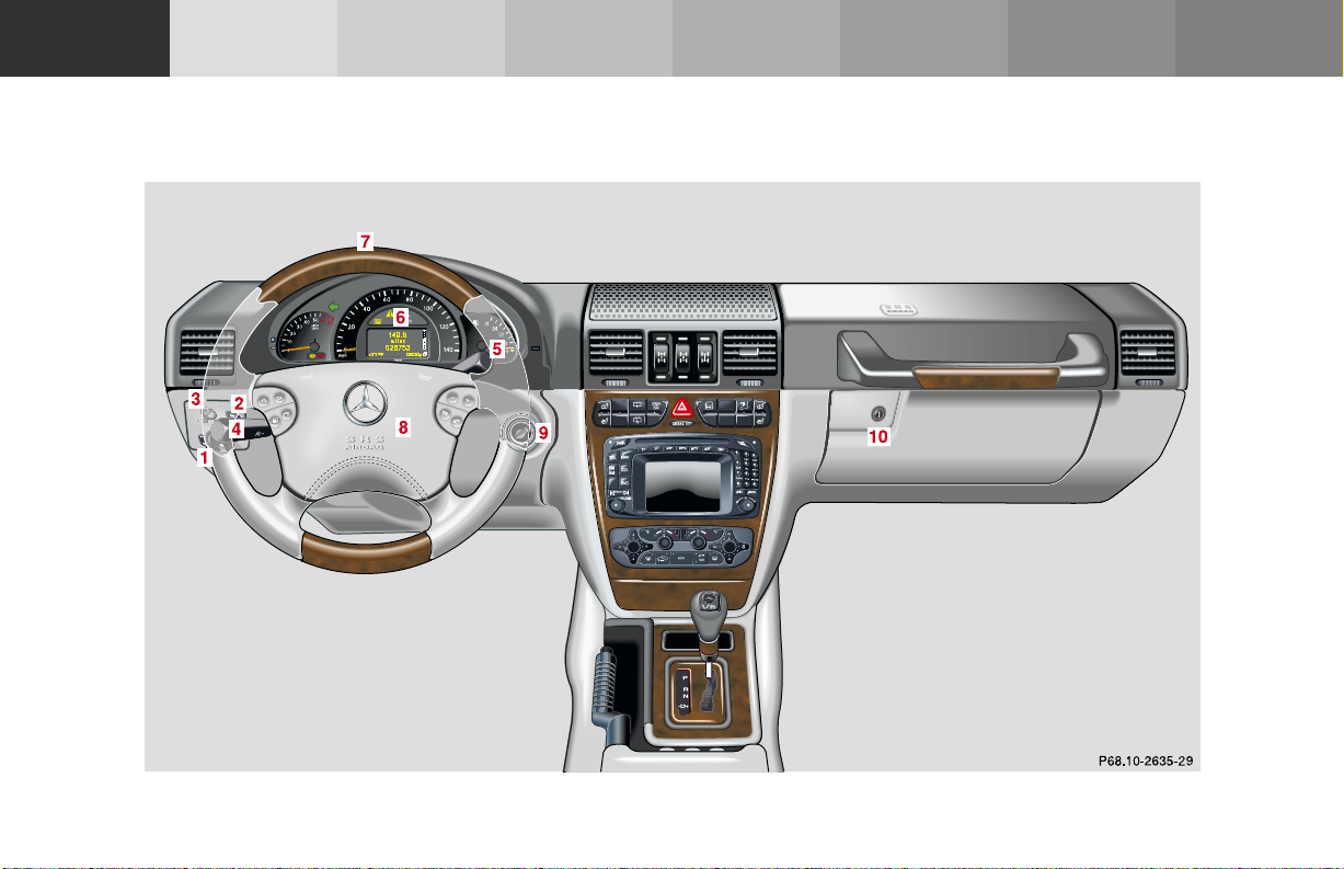
For adjustment of air outlets, refer to climate control,
see page 140.
1 Exterior lamp switch, see page 129
2 Headlamp cleaning system, see page 133
3 Exterior rear view mirror adjustment switch, see
page 80
4 Combination switch, see page 134
5 Control lever for Linguatronic voice control system
(optional), see seperate Operating Instructions
6 Instrument cluster, see page 84
7 Multifunction steering wheel, see page 90
8 Horn (with key in steering lock position 1 or 2),
Driver airbag, see page 68
9 Starter switch, see page 204
10 Glove box, see page 163
Instruments
and controls
Operation Driving
Instrument
cluster display
19Instruments and controls
Practical hints Car care Index
Technical
data
Instruments
and controls
Operation Driving
Center console
Instrument
cluster display
Practical hints Car care Index
Technical
data
20Instruments and controls

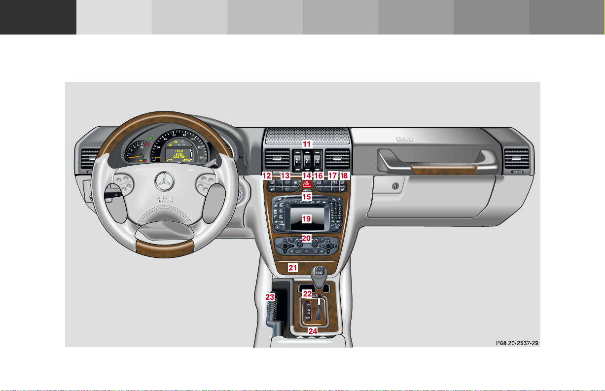
11 Differential-lock switch, see page 253
12 Left front seat heater switch, see page 52
13 Switch for rear window washer/wiper, see page 138
14 Hazard warning flasher switch, see page 139
15 AIRBAG OFF indicator lamp, see page 271
16 Central locking switch, see page 40
17 Antitheft alarm system, see page 42
Switch for Tow-away alarm, see page 43
18 Right front seat heater switch, see page 52
19 COMAND system (Cockpit Management and Data
System), see seperate operating instructions
20 Automatic climate control, see page 140
21 Ashtray with lighter, see page 168
22 Automatic transmission, see page 207
23 Parking brake, see page 215
24 Transfer case, see page 247
Instruments
and controls
Operation Driving
Instrument
cluster display
21Instruments and controls
Practical hints Car care Index
Technical
data
Instruments
and controls
Operation Driving
Instrument
cluster display
Practical hints Car care Index
Technical
22Instruments and controls
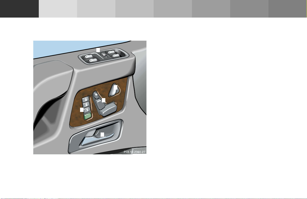
Door control panel 1 Door handle, pull to open, see page 34
2 Memory function, for storing seat, steering wheel
5
and exterior rear view mirrors, see page 48
3 Front seat adjustment switch, see page 45
4 Steering wheel adjustment switch, see page 78
5 Power window switches, see page 151
4
3
2
1
data
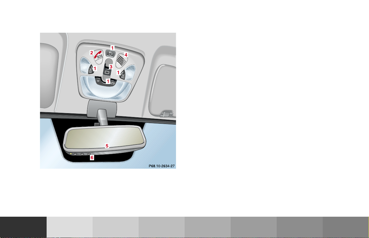
Overhead control panel 1 Interior lighting, see page 156
2 Tele Aid (emergency call system), see page 192
3 Sliding/pop-up roof, see page 154
4 Hands-free microphone for Tele Aid, telephone and
voice recognition system
5 Rear view mirror, see page 79
6 Garage door opener, see page 185
Instruments
and controls
Operation Driving
Instrument
cluster display
23Instruments and controls
Practical hints Car care Index
Technical
data

Instruments
and controls
Operation Driving
Operation
Vehicle keys ...................................... 26
Start lock-out ....................................28
General notes on the
central locking system ...............28
Central locking system ...................29
Radio frequency and
infrared remote control ............... 29
Locking and unlocking ................ 31
Choosing global or
selective mode on
remote control .............................. 31
Opening and closing windows
and sliding / pop-up roof from
outside ........................................... 32
Panic button .................................. 33
Mechanical keys ........................... 33
Doors .................................................. 34
Locking and unlocking
driver’s door manually ................ 36
Tailgate ..............................................37
Locking and unlocking
the tailgate manually ................... 38
Instrument
cluster display
Practical hints Car care Index
24Contents - Operation
Locking the tailgate
separately ...................................... 39
Central locking switch .................... 40
Automatic central locking ...............41
Emergency unlocking in
case of accident ...........................41
Antitheft alarm system ................... 42
Tow-away alarm ............................... 43
Easy-entry/exit feature .................. 44
Front seat adjustment ..................... 45
Synchronizing head restraints
and seat adjustment fore, aft ..... 47
Removal and installation
of front seat head restraints ......51
Seat heater, front ............................. 52
Seat heater, rear .............................. 54
Seat belts and
integrated restraint system ....... 56
Seat belts .......................................... 56
Seat belt nonusage
warning system ............................ 57
TM
BabySmart
airbag
deactivation system ................... 63
Technical
data
TM
Self-test BabySmart
without special child seat
installed ........................................ 63
Supplemental restraint system
(SRS) ............................................. 64
Emergency tensioning retractor
(ETR) .............................................65
Airbags ..............................................66
Safety guidelines for the
seat belt, emergency
tensioning retractor
and airbag .................................... 71
Infant and child
restraint systems .......................... 73
Steering wheel adjustment
(electrical) .................................... 78
Inside rear view mirror .................. 79
Antiglare night position .............. 79
Exterior rear view mirrors .............80
Instrument cluster ........................... 84
Multifunction steering wheel,
multifunction display ................. 90
Trip and main odometer
and sub menu .............................. 94

Audio systems ..................................96
Radio ..............................................96
CD player .......................................97
Telephone ..........................................98
Navigation system .......................... 103
Trip computer ................................. 104
Malfunction/warning
message memory ......................106
Individual settings .........................108
Setting the audio volume .............. 122
Coolant temperature gauge .......... 123
Flexible service system
(FSS) ............................................ 124
Engine oil level indicator .............. 127
Exterior lamp switch ..................... 129
Headlamp mode ............................. 130
Night security illumination ......... 132
Locator lighting .......................... 133
Headlamp cleaning system ...........133
Combination switch .......................134
Rear window wiper/washer ..........138
Hazard warning flasher switch ....139
Climate control .............................. 140
Rear passenger compartment
adjustable air outlets ................150
Power windows ...............................151
Sliding/pop-up roof ........................154
Interior lighting ..............................156
Door entry lamps ........................157
Rear interior lamps ....................158
Cargo compartment lamps ........159
Sun visors ........................................161
Illuminated vanity mirrors ...........161
Interior .............................................162
Storage compartments,
armrest and cup holder ............162
Glove box ......................................163
Ashtrays .......................................... 168
Lighter ............................................. 170
Floor mat ......................................... 170
Split rear seat bench ..................... 171
Rear seat head restraints ..........173
Enlarged cargo area ....................... 174
Cargo tie-down rings ..................... 174
Partition net .................................... 175
Loading instructions .....................178
Parcel net in
front passenger footwell ..........180
Cargo area cover blind .................. 180
Roof racks ........................................ 181
Brush guard ....................................182
Telephone, general ........................ 184
Cellular telephone ......................... 184
Garage door opener ....................... 185
Instruments
and controls
Operation Driving
Instrument
cluster display
25Contents - Operation
Practical hints Car care Index
Technical
data

Instruments
and controls
Operation Driving
Instrument
cluster display
Practical hints Car care Index
Technical
data
26Central locking system
Vehicle keys
Included with your vehicle are 2 electronic keys with
integrated radio frequency and infrared remote controls
plus removable mechanical key.
The locking tabs for the mechanical key portion of the
two electronic keys are a dif ferent color (black and grey)
to help distinguish each individual key.
Warn in g!
When leaving the vehicle always remove the key
from the starter switch, and lock your vehicle. Do
not leave children unattended in the vehicle, or
with access to an unlocked vehicle. Unsupervised
use of vehicle equipment may cause serious
personal injury.
Electronic key
The electronic key has an integrated radio frequency
and infrared remote control, plus removable mechanical
key.
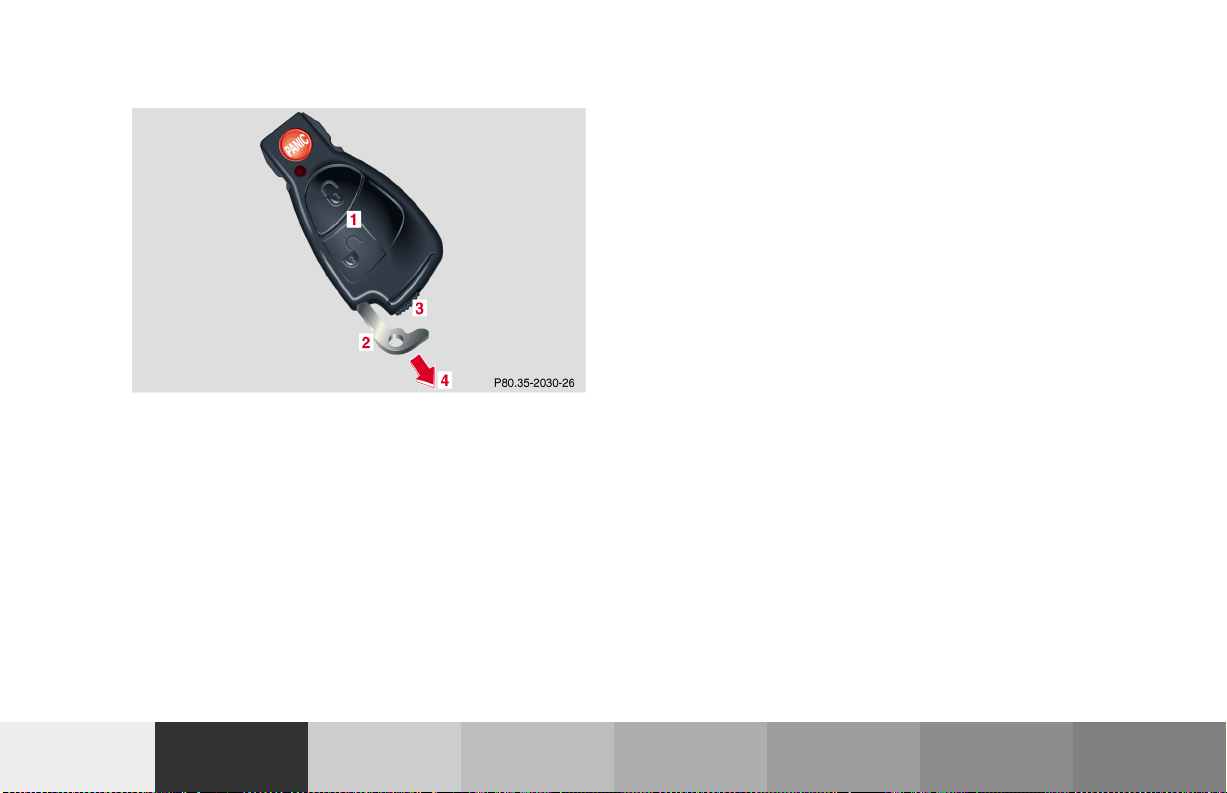
The remote control (1) operates all locks on the vehicle.
The mechanical key (2) works only in the driver’s door,
tailgate, and glove box lock.
When using the mechanical key (2) for lock operations,
it can be removed by sliding it out of the remote control.
To do so, move locking tab (3) to the right and slide the
mechanical key (2) in direction of arrow (4).
The remote control transmitter is located in the
electronic key.
The infrared receiver is located in the driver’s door
below the door handle.
Note:
Remove the mechanical key from the electronic key
when using valet parking service. To prevent access to
rear cargo area or storage compartments lock them
separately and retain the mechanical key.
See page 39 for separate locking of tailgate and
page 163 for locking of glove box.
Obtaining replacement keys
Your vehicle is equipped with a theft deterrent locking
system requiring a special key manufacturing process.
For security reasons, replacement keys can only be
obtained from your authorized Mercedes-Benz Light
Truck Center.
Instruments
and controls
Operation Driving
Instrument
cluster display
27Central locking system
Practical hints Car care Index
Technical
data

Instruments
and controls
Operation Driving
Instrument
cluster display
Practical hints Car care Index
28Central locking system
Technical
data
Start lock-out
Important!
Removing the electronic key from the starter switch
activates the start lock-out. The engine cannot be
started.
Inserting the electronic key in the starter switch
deactivates the start lock-out.
Note:
In case the engine cannot be started (vehicle’s battery is
in order), the system is not operational. Contact an
authorized Mercedes-Benz Light Truck Center or call
1-800-FOR-MERCedes (in the USA), or 1-800-387-0100
(in Canada).
General notes on the central locking system
If the electronic key is inserted in the starter switch, the
vehicle cannot be locked or unlocked with the remote
control.
If the vehicle cannot be locked or unlocked:
• Check the batteries of the electronic key, see
page 343, or synchronize the electronic key, see
page 345.
• Use the mechanical key to unlock the vehicle. To
start engine, insert the electronic key in the starter
switch. There could be a slight delay until the
electronic key can be turned in the starter switch.
Important!
When unlocking the driver’s door with the mechanical
key, the exterior lamps will flash and the alarm will
sound.
To cancel the alarm, insert the electronic key in the
starter switch or press button Œ or ‹ on the
electronic key.

Central locking system
Radio frequency and infrared remote control
The electronic key has an integrated radio frequency
and infrared remote control.
Due to the extended operational range of the remote
control, it could be possible to unintentionally lock or
unlock the vehicle by pressing the transmit button. If
one of the transmit buttons is pressed, the battery check
lamp lights up briefly – indicating that the batteries are
in order. See page 343 for checking batteries.
The vehicle doors, tailgate and fuel filler flap can be
centrally locked and unlocked via remote control.
Opening and closing the windows can only be done with
the infrared portion of the remote control. Aim
transmitter eye at the receiver of the driver’s door (6),
press and hold transmit button Œ or ‹,
seepage32.
If the electronic key is inserted in the starter switch, the
vehicle cannot be locked or unlocked with the remote
control.
4
3
2
1
5
P80.35-2033-26
1 Transmit button
‹ Locking
ΠUnlocking
2 Lamp for battery check (see page 343 for changing
batteries if it does not light up briefly)
3 PANIC button
4 Transmitter eye
5 Locking tab for mechanical key
29Central locking system
Instruments
and controls
Operation Driving
Instrument
cluster display
Practical hints Car care Index
Technical
data

Instruments
and controls
Operation Driving
6
6 Infrared receiver at the driver’s door
Instrument
cluster display
Practical hints Car care Index
Technical
data
30Central locking system

Locking and unlocking with remote control
Unlocking:
Press transmit button Œ. All turn signal lamps blink
once to indicate that the vehicle is unlocked.
The remote control can be programmed for two kinds of
unlocking modes (see below):
Selective unlocking mode –
Press transmit button Œ once to unlock driver’s door
and fuel filler flap.
Press transmit button Πtwice to unlock all doors,
fuel filler flap, and tailgate.
Global unlocking mode –
Press transmit button Πonce to unlock all doors,
fuel filler flap, and tailgate.
Notes:
If the tailgate was previously locked separately, it will
remain locked, see page 39.
The presently active unlocking mode (selective or
global) can only be determined by unlocking the vehicle
with the remote control (see below for changing mode).
If within 40 seconds of unlocking with the remote
control, neither door or tailgate is opened, the electronic
key is not inserted in the starter switch, or the central
locking switch is not activated, the vehicle will
automatically lock.
Locking:
Press transmit button ‹ once. All turn signal lamps
blink three times to indicate that the vehicle is locked. If
they do not blink three times, a door or the tailgate is
not properly closed.
Note:
If the vehicle cannot be locked or unlocked by pressing
the transmit button, then it may be necessary to change
the batteries in the electronic key (if ok, battery check
lamp in electronic key will light briefly when pressing
transmit button) or to synchronize the remote control,
see pages 343 and 345.
Choosing global or selective mode on remote control
Press and hold transmit buttons ‹ and Œ
simultaneously for 6 seconds to reprogram the remote
control. Battery check lamp will blink two times
indicating the completed mode change.
Instruments
and controls
Operation Driving
Instrument
cluster display
31Central locking system
Practical hints Car care Index
Technical
data

Instruments
and controls
Operation Driving
Instrument
cluster display
Practical hints Car care Index
32Central locking system
Technical
data
Opening and closing windows and sliding/pop-up
roof from outside
(summer opening/ convenience feature)
Aim transmitter eye of remote control at the driver’s
door receiver.
Summer opening:
The sliding/ pop-up roof and all side windows can be
opened automatically.
Continue to press transmit button Πafter unlocking
the vehicle.
The windows and sliding/pop-up roof begin to open
after approximately 1 second.
To interrupt opening procedure, release transmit
button.
Convenience feature:
The sliding/pop-up roof and the side windows can be
closed.
Continue to press transmit button ‹ after locking
the vehicle.
The windows and sliding/ pop-up roof begin to close
after approximately 1 second.
To interrupt closing procedure, release transmit button.
Ensure that all side windows and the sliding/pop-up
roof are properly closed before leaving the vehicle.
Warn in g!
Never operate the windows or sliding/ pop-up roof
if there is the possibility of anyone being harmed
by the opening or closing procedure.
In case the procedure causes potential danger, the
procedure can be immediately halted by releasing
the remote control button. To reverse direction of
movement press Œ for opening or ‹ for
closing.
Note:
If the windows and sliding/pop-up roof cannot be
operated automatically by pressing the transmit button
of the remote control then it may be necessary to cha nge
the batteries in the electronic key (if ok, battery check
lamp in electronic key will light briefly when
transmitting), or to synchronize the remote control, see
page 343 and 345.

Panic button
(1) This device may not cause harmful interference, and
(2) this device must accept any interference received,
including interference that may cause undesired
operation.
Any unauthorized modification to this device could void
to the user’s authority to operate the equipment.
Mechanical keys
The mechanical keys work only in the driver’s door,
tailgate, and storage compartment locks.
Instruments
and controls
P80.35-2034-26
To activate press and hold button (1) for at least one
second. An audible alarm and blinking exterior lamps
will operate for approximately 3 minutes.
To deactivate press button (1) again, or insert electronic
key in starter switch.
Note:
For operation in the USA only: This device complies
with Part 15 of the FCC Rules. Operation is subject to
the following two conditions:
Operation Driving
Instrument
cluster display
Notes:
The mechanical key does not operate the central locking
system or arm or disarm the antitheft alarm system.
The alarm sounds when unlocking the driver’s door or
tailgate. Cancel alarm by turning electronic key in
starter switch to position 1, or with the remote control
by pressing button Œ or ‹.
Unlocking and locking the driver’s door manually, see
page 36.
Unlocking the tailgate manually, see page 38.
Locking the tailgate separately, see page 39.
33Central locking system
Practical hints Car care Index
Technical
data

Instruments
and controls
Operation Driving
Doors
Instrument
cluster display
2359
Practical hints Car care Index
Technical
data
34Central locking system
To open the door, press the lock cylinder (1) and pull on
the door handle (2).
Note:
The passenger side door cannot be unlocked using the
mechanical key.
3 Front door from inside:
Pull handle to unlock.
4 Individual door from inside:
Push button down to lock.
Pull lock button up to unlock.
Important!
The mechanical key does not operate the central locking
system or arm or disarm the antitheft alarm system.

When you lock the driver’s door with the mechanical
key, the door lock button should move down.
Each individual door must be locked with the respective
door lock button – the driver’s door can only be locked
when it is closed.
Notes:
The alarm sounds when unlocking the driver’s door
with the mechanical key. Cancel alarm by turning
electronic key in starter switch to position 1, or with the
remote control by pressing button Œ or ‹.
If the vehicle has previously been locked from the
outside, only the door being opened from the inside will
unlock, and the alarm will come on. The doors, the
tailgate and fuel filler flap remain locked.
In case of a malfunction in the central locking system
the doors can be locked and unlocked individually.
To lock, push down lock buttons and turn mechanical
key in driver’s door lock to position 4. In addition lock
the tailgate.
To unlock the driver’s manually, see page 36.
Rear doors, previously centrally locked, can be opened
from inside by first unlocking the vehicle with the
central locking switch, see page 40, or by first pulling
up the door lock button.
If the fuel filler flap cannot be opened, see page 347.
Instruments
and controls
Operation Driving
Instrument
cluster display
35Central locking system
Practical hints Car care Index
Technical
data

Instruments
and controls
Operation Driving
Instrument
cluster display
Practical hints Car care Index
Technical
data
36Central locking system
Locking and unlocking driver’s door manually
3
1
1 To open, press lock cylinder
2 Locking driver’s door
3 Unlocking driver’s door
If the vehicle cannot be locked or unlocked using the
remote control, lock or unlock the driver’s door using
the mechanical key.
Notes:
The alarm sounds when unlocking the driver’s door
with the mechanical key. Cancel alarm by turning
electronic key in starter switch to position 1.
2
The passenger door cannot be unlocked manually.

Tailgate
2
1
2184
To open the tailgate, press the lock cylinder (2) and pull
on the tailgate handle (1).
Note:
When unlocking the tailgate with the mechanical key,
the exterior lamps will flash and the alarm will sound.
To cancel the alarm, insert the electronic key in the
starter switch to position 1 or press button Œ
or ‹ on the electronic key.
Important!
Only drive with the tailgate closed as otherwise exhaust
fumes may enter the vehicle interior.
Warn in g!
The tailgate swings open to one side. Always make
sure there is sufficient clearance for tailgate.
Instruments
and controls
Operation Driving
Instrument
cluster display
37Central locking system
Practical hints Car care Index
Technical
data

Instruments
and controls
Operation Driving
Instrument
cluster display
Practical hints Car care Index
Technical
data
38Central locking system
Locking and unlocking the tailgate manually
1 Locking
2 Unlocking
If the tailgate cannot be unlocked with remote control
due to a malfunction, unlock the tailgate using the
mechanical key.
Note:
When unlocking the tailgate with the mechanical key,
the exterior lamps will flash and the alarm will sound.
To cancel the alarm, insert the electronic key in the
starter switch to position 1 or press button Œ
or ‹ on the electronic key.

Locking the tailgate separately Locking tailgate separately:
Lock tailgate using the mechanical key (1).
The tailgate will remain locked, even if the vehicle is
centrally unlocked.
Cancellation of separate tailgate locking:
Turn mechanical key in lock cylinder to position (2).
Instruments
and controls
Operation Driving
Instrument
cluster display
39Central locking system
Practical hints Car care Index
Technical
data

Instruments
and controls
Operation Driving
Instrument
cluster display
Practical hints Car care Index
Technical
data
40Central locking system
Central locking switch
P54.25-2499-26
1 Locking
2 Unlocking
The central locking switch is located in the center
console.
Doors and tailgate can only be locked with the central
locking switch, if all doors and the tailgate are closed.
If the vehicle was previously locked with the central
locking switch, while in the selective remote control
mode, only the door opened from the inside is unlocked.
If the vehicle was previously locked with the central
locking switch, while in the global remote control mode,
the complete vehicle is unlocked when a door is opened
from the inside.
Notes:
If the vehicle was previously locked with the remote
control, the doors and tailgate cannot be unlocked with
the central locking switch.
The fuel filler flap cannot be locked or unlocked with
the central locking switch.
If the vehicle has previously been locked from the
outside, opening a door from the inside will trigger the
alarm. To cancel the alarm, insert the electronic key in
the starter switch or press button Œ or ‹ on the
electronic key.
Warn in g!
When leaving the vehicle always remove the
electronic key from the starter switch, and lock
your vehicle. Do not leave children unattended in
the vehicle, or with access to an unlocked vehicle.
Unsupervised use of vehicle equipment may cause
serious personal injury.

Automatic central locking
Wit h the automatic central lockin g system activated, the
doors and tailgate are locked at vehicle speeds of
approximately 9 mph (15 km / h) or more. The fuel filler
flap remains unlocked.
The automatic central locking function can be switched
on or off in the individual setting menu “VEHICLE” –
“AUTOMATIC DOOR LOCK”, see page 118.
Notes:
If doors are unlocked with the central locking switch
after activating the automatic central locking, and
neither door is opened, then the doors remain unlocked
even at vehicle speeds of approximately 9 mph
(15 km / h) or more.
If a door is opened from the inside at speeds of
approximately 9 mph (15 km /h) or less with the
automatic central locking activated, the door will again
be automatically locked at speeds of approximately
9 mph (15 km / h) or more.
Important!
When towing the vehicle, or with the vehicle on a
dynamometer test stand, please, note the following:
With the automatic central locking activated and the
electronic key in starter switch position 2, the vehicle
doors will lock if the left front wheel spin at vehicle
speeds of approximately 9 mph (15 km / h) or more.
Emergency unlocking in case of accident
The doors unlock automatically a short time after an
accident in which an airbag or emergency tensioning
retractor deploys (this is intended to aid rescue and
exit).
Instruments
and controls
Operation Driving
Instrument
cluster display
41Central locking system
Practical hints Car care Index
Technical
data

Instruments
and controls
Operation Driving
Instrument
cluster display
Practical hints Car care Index
Technical
data
42Antitheft alarm system
Antitheft alarm system
P54.25-2500-26
1 Indicator lamp in switch located in center console
The antitheft alarm is automatically armed or disarmed
with the remote control by locking or unlocking the
vehicle.
The antitheft alarm is armed within approximately
15 seconds after locking the vehicle.
A blinking lamp (1) indicates that the alarm is armed.
Operation:
Once the alarm system has been armed, the exterior
vehicle lamps will flash and an alarm will sound when
someone:
• opens a door,
• opens the tailgate,
• opens the hood,
• attempts to raise the vehicle.
The alarm will last approximately 3 minutes in form of
flashing exterior lamps. At the same time an alarm will
sound for 30 seconds. The alarm will stay on even if the
activating element (a door, for example) is immediately
closed. If the alarm stays on for more than 20 seconds,
an emergency call is initiated automatically. See Tele
Aid on page 192.
Notes:
When unlocking the driver’s door or the tailgate with
the mechanical key, the exterior lamps will flash and
the alarm will sound.
To cancel the alarm, insert the electronic key in the
starter switch to position 1 or press button Œ
or ‹ on the electronic key.

Tow-away al arm
The switch is located in the center console.
1 Press to switch off tow-away alarm
2 Indicator lamp
Once the alarm system has been armed, the exterior
vehicle lamps will flash and an alarm will sound when
someone attempts to raise the vehicle.
The alarm will last approximately 3 minutes in form of
flashing exterior lamps. At the same time an alarm will
sound for 30 seconds. The alarm will stay on even if the
vehicle is immediately lowered. To cancel the alarm,
insert the electronic key in the starter switch or press
button Œ or ‹ on the electronic key.
If the alarm stays on for more than 20 seconds, an
emergency call is initiated automatically. See Tele Aid
on page 192.
To prevent triggering the tow -away alarm feature, switch
off the tow-away alarm before towing the vehicle, or
when parking on a surface subject to movement, such
as a ferry or auto train.
To do so, turn electronic key in starter switch to
position 1 or 0, or remove electronic key from starter
switch. Press tow-away alarm switch (1). The indicator
lamp (2) illuminates briefly.
Exit vehicle, and lock vehicle with the electronic key.
The tow-away alarm remains switched off until the
vehicle is locked again with the electronic key, at which
time it is automatically reactivated.
Instruments
and controls
Operation Driving
Instrument
cluster display
43Tow-away alarm
Practical hints Car care Index
Technical
data

Instruments
and controls
Operation Driving
Instrument
cluster display
Practical hints Car care Index
44Easy-entry/exit feature
Technical
data
Easy-entry/exit feature
With the easy-entry/exit feature activated the steering
wheel tilts upwards. This allows easier entry into and
exit from the vehicle when the driver’s door is opened.
However, the engine must be turned off.
The easy-entry/exit feature can be switched on or off in
the individual setting menu “CONVENIENCE” –
“EASY-ENTRY FEATURE ACTIVATE”, see page 120.
When the electronic key is inserted in the starter switch
and the driver’s door is closed the steering wheel
returns to the last position set for it.
Warn in g!
You must ensure that no one can become trapped
or injured by the moving steering wheel when the
easy-entry/ exit feature is in operation and the
driver’s door is being opened or the electronic key
is removed from the starter switch. Do not leave
children unattended in the vehicle, or with access
to an unlocked vehicle. Unsupervi sed use of vehicle
equipment may cause serious personal injury.

Front seat adjustment
Wa rn in g!
Do not adjust the driver’s seat while driving.
Adjusting the seat while driving could cause the
driver to lose control of the vehicle.
Never ride in a moving vehicle with the seat back
reclined. Sitting in an excessively reclined position
can be dangerous. You could slide under the seat
belt in a collision. If you slide under it, the belt
would apply force at the abdomen or neck. That
could cause serious or fatal injuries. The seat back
and seat belts provide the best restraint when the
wearer is in an upright position and belts are
properly positioned on the body.
Never place hands under seat or near any moving
parts while a seat is being adjusted.
When leaving the vehicle always remove the
electronic key from the starter switch, and lock
your vehicle.
The power seats can also be operated with the
driver’s or front passenger door open. Do not leave
children unattended in the vehicle, or with access
to an unlocked vehicle. Unsupervi sed use of vehicle
equipment may cause serious personal injury.
To operate the front power seat adjustment switches,
turn the electronic key in starter switch to position 1
or 2 (with respective front door open, the power seats
can also be operated with the electronic key removed or
in starter switch position 0).
Note:
If the passenger side seat backrest is set to a full upright
position and the passenger seat is moved fully forward,
the cup holder next to the armrest must be removed
(page 166) and the cup holder in the passenger footwell
(page 167) must be folded closed.
Instruments
and controls
Operation Driving
Instrument
cluster display
45Seats
Practical hints Car care Index
Technical
data

Instruments
and controls
Operation Driving
Instrument
cluster display
Practical hints Car care Index
Technical
data
46Seats
Power seat
5
4
1 3
2 2
The switches are located in each front door.
We recommend to adjust the power seat in the following
order:
1 Seat, up/down
Press the switch (up/down direction) until
comfortable seating position with still sufficient
headroom is reached.
2 Seat adjustment, fore/ aft
Press the switch (fore / aft direction) until a
comfortable seating position is reached that still
allows you to reach the accelerator/brake pedal
safely. The position should be as far rearward as
possible, consistent with ability to properly operate
controls.
3 Seat cushion tilt
Press the switch in the direction of the arrow until
your legs are lightly supported.
4 Backrest tilt
Press the switch in the direction of the arrow until
your arms are slightly angled when holding the
steering wheel.
5 Head restraint
The height of the head restraint is adjusted
automatically with the seat so that the back of the
head is supported approximately at ear level. Adjust
the head restraint using the switch to support the
back of your head approximately at ear level.

P91.10-2360-26
Adjust the head restraint angle by hand. Push or pull
the head restraint in direction of arrow.
For notes on inside rear view mirrors adjustment, see
page 79;
For exterior rear view mirrors adjustment, see page 80
and for steering wheel adjustment, see page 78.
Synchronizing head restraints and seat adjustment fore, aft
If the power supply was interrupted (battery
disconnected or empty), the head restraints and the seat
adjustment fore, aft are no longer adjusted
automatically.
To resynchronize the adjustment feature, turn
electronic key in starter switch to position 2, move the
seat completely forward and the head restraint fully
down.
To recall the desired seat position push and hold
position button (2) until the adjustment has stopped, see
page 48 for notes on the memory function.
Caution!
Do not remove head restraints except when mounting
seat covers. For removal refer to head restraints, front
on page 51. Whenever restraints have been removed be
sure to reinstall them before driving.
Instruments
and controls
Operation Driving
Instrument
cluster display
47Seats
Practical hints Car care Index
Technical
data

Instruments
and controls
Operation Driving
Instrument
cluster display
Practical hints Car care Index
Technical
data
48Seats
Memory function
2
1
The buttons are located on the doors.
1 Memory button, used to store selected positions
which can be retrieved by pressing
2 Position buttons
Warn in g!
Do not activate the memory function while driving.
Activating the memory function while driving
could cause the driver to lose control of the vehicle.
Together with the driver’s seat position you can store
the positions for steering wheel and exterior rear view
mirrors.
For the front passenger seat you can store the seat
position.
Three stored positions for the driver’s seat are available
for each of the two electronic keys.
This is only possible if you select “ON” in the menu
“SETTINGS KEY-DEPENDENT”. Refer to individual
setting menu “CONVENIENCE” – “SETTINGS KEYDEPENDENT”, see page 120.

Storing positions into memory:
With the electronic key in starter switch position 1 or 2
or with the relevant door open and the electronic key
inserted in the starter switch.
Adjust the seat to the desired position, see page 46.
Driver’s seat:
You can also adjust the steering wheel and the exterior
rear view mirrors electrically for the driver’s seat. See
page 80 for exterior rear view mirror adjustment and
page 78 for steering wheel adjustment.
Push memory button (1), release and push the position
button (2) within 3 seconds.
Recalling positions from memory:
To recall a seat /steering wheel/exterior rear view
mirror position, push and hold button (2) to selected
memory position until the adjustment has stopped.
The seat/ steering wheel / exterior rear view mirror
movement stops when the button is released.
Caution!
Do not operate the power seats using the memory
button if the backrest is in an excessively reclined
position. Doing so could cause damage to front or rear
seats.
First move backrest to an upright position.
Instruments
and controls
Operation Driving
Instrument
cluster display
49Seats
Practical hints Car care Index
Technical
data

Instruments
and controls
Operation Driving
Instrument
cluster display
Practical hints Car care Index
Technical
data
50Seats
Important!
Prior to operating the vehicle, the driver should check
and adjust if necessary the seat height, seat position
fore and aft, and backrest angle to insure adequate
control, reach and comfort. The head restraint should
also be adjusted for proper height. See also airbag
section for proper seat positioning.
In addition, also adjust the steering wheel to ensure
adequa te control, reach, operation and comfort. Both the
inside and outside rear view mirrors should be adjusted
for adequate rearward vision.
Fasten seat belts. Infants and small children should be
seated in a properly secured restraint system that
complies with U.S. Federal Motor Vehicle Safety
Standard 213 and Canadian Motor Vehicle Safety
Standard 213.
All seat, head restraint, steering wheel, and rear view
mirror adjustments as well as fastening of seat belts
should be done before the vehicle is put into motion.
Warn in g!
Children 12 years old and under must never ride in
the front seat, except in a Mercedes-Benz
authorized BabySmart
which operates with the BabySmart
TM
compatible child seat,
TM
system
installed in the vehicle to deactivate the passenger
side front airbag when it is properly installed.
Otherwise they will be struck by the airbag when it
inflates in a crash. If this happens, serious or fatal
injury can result.
According to accident statistics, children are safer
when properly restrained in the rear seating
positions than in the front seating positions.
Infants and small children must ride in back seats
and be seated in an appropriate infant or child
restraint system, which is properly secured with
the vehicle’s seat belt, fully in accordance with the
child seat manufacturer’s instructions.
A child’s risk of serious or fatal injuries is
significantly increased if the child restraints are
not properly secured in the vehicle and the child is
not properly secured in the child restraint.

Removal and installation of front seat head restraints
Note:
Tilt the backrest rearward for easier removal and
installation of the head restraints.
Instruments
and controls
1
Caution!
Do not remove head restraints except when mounting
seat covers. Whenever restraints have been removed be
sure to reinstall them before driving.
Operation Driving
Instrument
cluster display
To rem ove:
Press switch (1) upwards and hold until the head
restraint is fully extended. Pull head restraint out.
To i nstall:
Press switch (1) upwards and hold for about 5 seconds.
Press the head restraint down until it engages.
Adjust head restraint to the desired position.
Adjusting head restraint, see page 46.
Warn in g!
For your protection, drive only with properly
positioned head restraints.
Adjust head restraint to support the back of the
head approximately at ear level.
Do not drive the vehicle without the seat head
restraints. Head restraints are intended to help
reduce injuries during an accident.
51Seats
Practical hints Car care Index
Technical
data

Instruments
and controls
Operation Driving
Instrument
cluster display
Practical hints Car care Index
Technical
data
52Seats
Seat heater, front
P54.25-2501-26
The switch is located in the center console.
The front seat heaters can be switched on with the
electronic key in starter switch position 1 or 2.
Press switch to turn on seat heater:
1 Normal seat heating mode. One indicator lamp in
the switch lights up.
2 Rapid seat heating mode. Both indicator lamps in
the switch light up. After approximately 5 minutes
in the rapid seat heating mode, the seat heater
automatically switches to normal operation and on ly
one indicator lamp will stay on.
Turning off seat heater:
If one indicator lamp is on, press upper half of switch.
If both indicator lamps are on, press lower half of
switch.
If left on, the seat heater automatically turns off after
approximately 30 minutes of operation.

Notes:
When in operation, the seat heater consumes a large
amount of electrical power. It is not advisable to use the
seat heater longer than necessary.
The seat heaters may automatically switch off if too
many power-consuming devices are switched on at the
same time, or if the battery charge is low. When this
occurs, the indicator lamp in the switch will blink (both
indicator lamps blink during rapid seat heating mode).
The seat heaters will switch on again automatically as
soon as sufficient voltage is available.
If the blinking of the indicator lamps is distracting to
you, the seat heaters can be switched off.
Instruments
and controls
Operation Driving
Instrument
cluster display
53Seats
Practical hints Car care Index
Technical
data

Instruments
and controls
Operation Driving
Instrument
cluster display
Practical hints Car care Index
Technical
data
54Seats
Seat heater, rear
1
The switch is located on the center pillar.
The rear seat heaters can be switched on with the
electronic key in starter switch position 1 or 2.
2
2561
Press switch to turn on seat heater:
1 Normal seat heating mode. One indicator lamp in
the switch lights up.
2 Rapid seat heating mode. Both indicator lamps in
the switch light up. After approximately 5 minutes
in the rapid seat heating mode, the seat heater
automatically switches to normal operation and on ly
one indicator lamp will stay on.
Turning off seat heater:
If one indicator lamp is on, press upper half of switch.
If both indicator lamps are on, press lower half of
switch.
If left on, the seat heater automatically turns off after
approximately 30 minutes of operation.

Notes:
When in operation, the seat heater consumes a large
amount of electrical power. It is not advisable to use the
seat heater longer than necessary.
The seat heaters may automatically switch off if too
many power-consuming devices are switched on at the
same time, or if the battery charge is low. When this
occurs, the indicator lamp in the switch will blink (both
indicator lamps blink during rapid seat heating mode).
The seat heaters will switch on again automatically as
soon as sufficient voltage is available.
If the blinking of the indicator lamps is distracting to
you, the seat heaters can be switched off.
The heater circuit will be switched off for safety reasons
to prevent a build up of heat and overheating of the seat,
(for example, seat is folded forward).
Instruments
and controls
Operation Driving
Instrument
cluster display
55Seats
Practical hints Car care Index
Technical
data

Instruments
and controls
Operation Driving
Instrument
cluster display
Practical hints Car care Index
Technical
data
56Restraint systems
Seat belts and integrated restraint system
Your vehicle is equipped with seat belts for all seats,
emergency tensioning retractors for front and second
row outboard seat belts, and single front airbags. Their
protective functions are designed to complement one
another.
Seat belts
Important!
Laws in most states and all Canadian provinces require
seat belt use.
All states and provinces require use of child restraints
that comply with U.S. Federal Motor Vehicle Safety
Standard 213 and Canadian Motor Vehicle Safety
Standard 213.
All child restraint systems are designed to be secured in
vehicle seats by lap belts or the lap belt portion of a lapshoulder belt.
For your safety and that of your passengers we strongly
recommend their use.
Warn in g!
Children 12 years old and under must never ride in
the front seat, except in a Mercedes-Benz
authorized BabySmart
which operates with the BabySmart
TM
compatible child seat,
TM
system
installed in the vehicle to deactivate the passenger
side front airbag when it is properly installed.
Otherwise they will be struck by the airbag when it
inflates in a crash. If this happens, serious or fatal
injury will result.
According to accident statistics, children are safer
when properly restrained in the rear seating
positions than in the front seating positions.
Infants and small children must ride in back seats
and be seated in an appropriate infant or child
restraint system, which is properly secured with
the vehicle’s seat belt, fully in accordance with the
child seat manufacturer’s instructions.
A child’s risk of serious or fatal injuries is
significantly increased if the child restraints are
not properly secured in the vehicle and the child is
not properly secured in the child restraint.

Wa rn in g!
Never ride in a moving vehicle with the backrest
reclined. Sitting in an excessively reclined position
can be dangerous. You could slide under the seat
belt in a collision. If you slide under it, the belt
would apply force at the abdomen or neck. That
could cause serious or even fatal injuries. The
backrest and seat belt provide the best restraint
when the wearer is in an upright position and the
belt is properly positioned on the body.
Note:
For cleaning and care of the seat belts, see page 354.
Seat belt nonusage warning system
After starting the engine, a warning sounds a short time
and the seat belt warning lamp < remains
illuminated if the driver’s seat belt is not fastened.
Warn in g!
Failure to wear and properly fasten and position
your seat belt greatly increases your risk of
injuries and their likely severity in an accident.
You and your passengers should always wear seat
belts.
If you are ever in an accident, your injuries can be
considerably more severe without your seat belt
properly buckled. Without your seat belt buckled,
you are much more likely to hit the interior of the
vehicle or be ejected from it. You can be seriously
injured or killed.
In the same crash, the possibility for injury or
death is lessened if you are wearing your seat belt.
Warn in g!
Never let more people ride in the vehicle than there
are seat belts available. Be sure everyone riding in
the vehicle is correctly restrained with a separate
seat belt.
Instruments
and controls
Operation Driving
Instrument
cluster display
57Restraint systems
Practical hints Car care Index
Technical
data

Instruments
and controls
Operation Driving
Instrument
cluster display
Practical hints Car care Index
Technical
data
58Restraint systems
Fastening of seat belts
1 Latch plate
2 Buckle
3 Release button
Push latch plate (1) into buckle (2) until it clicks. Do not
twist the belt. A twisted seat belt may cause injury.
To help avoid severe or fatal injuries, the lap belt must
be positioned as low as possible on your hips and not
across the abdomen.
Warn in g!
Always fasten your seat belt before driving off.
Always make sure your passengers are properly
restrained – even those sitting in the rear.

4
2302
Instruments
and controls
Tighten the lap portion to a snug fit by pulling shoulder
portion up.
The shoulder portion of the seat belt must be pulled
snug and checked for snugness immediately after
engaging it.
Adjust seat belt so that shoulder portion is located as
close as possible to the middle of your shoulder (it
should not touch the neck). For this purpose, you can
adjust the height of the belt outlet. Five positions are
available.
Operation Driving
Instrument
cluster display
4 Button for belt outlet height adjustment
To raise, slide belt height adjustment upward.
To lower, press button (4) and slide belt outlet
downward.
Caution!
For safety reasons, avoid adjusting the seat or backrest
into positions which could affect the correct seat belt
positioning.
59Restraint systems
Practical hints Car care Index
Technical
data

Instruments
and controls
Operation Driving
Operation of seat belts
The inertia reel stops the belt from unwinding during
sudden vehicle stops or when quickly pulling on the
belt. The locking function of the reel may be checked by
quickly pulling out the belt.
Unfastening of seat belts
Push the release button (3) in the belt buckle (2).
Allow the retractor to completely rewind the seat belt by
guiding the latch plate (1).
Instrument
cluster display
Practical hints Car care Index
60Restraint systems
Warn in g!
USE SEAT BELTS PROPERLY.
• Seat belts can only work when used properly.
Never wear seat belts in any other way than as
described in this section, as that could result
in serious injuries in case of an accident.
• Each occupant should wear their seat belt at all
times, because seat belts help reduce the
likelihood of and potential severity of injuries
in accidents, including rollovers. The
integrated restraint system includes “SRS”
(driver airbag and front passenger airbag) and
“ETR” (seat belt emergency tensioning
retractors for the driver’s seat, passenger’s seat
and rear outboard passenger seats). The
system is designed to enhance the protection
offered to properly belted occupants in certain
frontal (front airbags) impacts which exceed
preset deployment thresholds.
Technical
data

• Never wear the shoulder belt under your arm,
against your neck or off your shoulder. In a
crash, your body would move too far forward.
That would increase the chance of head and
neck injuries. The belt would also apply too
much force to the ribs or abdomen, which
could severely injure internal organs such as
your liver or spleen.
• Never wear belts over rigid or breakable
objects in or on your clothing, such as
eyeglasses, pens, keys etc., as these might
cause injuries.
• Position the lap belt as low as possible on your
hips and not across the abdomen. If the belt is
positioned across your abdomen, it could cause
serious injuries in a crash.
• Each seat belt should never be used for more
than one person at a time. Do not fasten a seat
belt around a person and another person or
other objects.
• Belts should not be worn twisted. In a crash,
you wouldn’t have the full width of the belt to
manage impact forces. The twisted belt against
your body could cause injuries.
• Pregnant women should also use a lapshoulder belt. The lap belt portion should be
positioned as low as possible on the hips to
avoid any possible pressure on the abdomen.
• Never place your feet on the instrument panel
or on the seat. Always keep both feet on the
floor in front of the seat.
Instruments
and controls
Operation Driving
Instrument
cluster display
61Restraint systems
Practical hints Car care Index
Technical
data

Instruments
and controls
Operation Driving
Instrument
cluster display
Practical hints Car care Index
Technical
data
62Restraint systems
Wa rn in g!
USE CHILD RESTRAINTS PROPERLY.
Children 12 years old and under must never ride in
the front seat, except in a Mercedes-Benz
authorized BabySmart
which operates with the BabySmart
TM
compatible child seat,
TM
system
installed in the vehicle to deactivate the passenger
front airbag when it is properly installed.
Otherwise they will be struck by the airbag when it
inflates in a crash. If this happens, serious or fatal
injury will result.
According to accident statistics, children are safer
when properly restrained in the rear seating
positions than in the front seating positions.
Infants and small children must ride in back seats
and be seated in an appropriate infant or child
restraint system, which is properly secured with
the vehicle’s seat belt, fully in accordance with the
child seat manufacturer’s instructions.
A child’s risk of serious or fatal injuries is
significantly increased if the child restraints are
not properly secured in the vehicle and the child is
not properly secured in the child restraint.
Children too big for child restraint systems must
ride in back seats using regular seat belts. Position
shoulder belt across chest and shoulder, not face or
neck. A booster seat may be necessary to achieve
proper belt positioning.

TM
BabySmart
Special BabySmart
airbag deactivation system
TM
compatible child seats, designed
for use with the Mercedes-Benz system and available at
any authorized Mercedes-Benz Light Truck Center are
required for use with the BabySmart
TM
airbag
deactivation system. With the special child seat properly
installed, the passenger front airbag will not deploy.
The ü indicator lamp located in the center console
will be illuminated, except with electronic key removed
or in starter switch position 0.
TM
Self-test BabySmart
without special child seat
installed
After turning electronic key in starter switch to
position 1 or 2, the ü indicator lamp located in the
center console comes on for approximately 6 seconds
and then extinguishes.
If the indicator lamp should not come on or is
continuously lit, the system is not functioning. You must
see an authorized Mercedes-Benz Light Truck Center
before seating any child on the front passenger seat. See
page 271 for notes on the ü indicator lamp.
Warn in g!
TM
The BabySmart
airbag deactivation system will
ONLY work with a special child seat designed to
operate with it. It will not work with child seats
which are not BabySmart
TM
compatible.
Never place anything between seat cushion and
child seat (e.g. pillow), since it reduces the
effectiveness of the deactivation system. The
bottom of the child seat must make full contact
with the passenger seat cushion. An incorrectly
mounted child seat could cause injuries to the
child in case of an accident instead of protecting
the child.
Follow the manufacturer’s instructions for
installation of special child seats.
The passenger front airbag will not deploy only if
the ü indicator lamp remains illuminated.
Please be sure to check the indicator every time
you use the special system child seat. Should the
light go out while the restraint is installed, please
check installation. If the light remains out, do not
use the BabySmart
TM
restraint to transport children
on the front passenger seat until the system has
been repaired.
Instruments
and controls
Operation Driving
Instrument
cluster display
BabySmartTM is a trademark of Siemens Automotive Corp.
63Restraint systems
Practical hints Car care Index
Technical
data

Instruments
and controls
Operation Driving
Instrument
cluster display
Practical hints Car care Index
64Restraint systems
Technical
data
Supplemental restraint system (SRS)
Airbags are intended as a supplement to seat belts.
Airbags alone cannot protect as well as airbags plus
seat belts in impacts for which the airbags were
designed to operate, and do not afford any protection
whatsoever in crashes for which the airbags are not
designed to deploy.
The SRS uses two crash severity levels (thresholds) to
activate either the Emergency Tensioning Retractor
(ETR) or front airbag or both. Activation depends on the
direction and severity of the impact exceeding the
preset thresholds and whether the seat belt is fastened.
Seat belt fastened
• first threshold exceeded: ETR activates
• second threshold exceeded: airbag also activates
Seat belt not fastened
Front seats:
• first threshold exceeded:
airbag activates, but not ETR
Rear outer seats:
• first threshold exceeded:
ETR activates
Notes:
Driver, front passenger and rear outer seat systems
operate independently of each other.
Heavy objects on the front passenger seat can appear to
the “SRS” to indicate the presence of an occupant in
that seat which causes the passenger front airbag to
deploy in a crash exceeding the appropriate threshold.

Emergency tensioning retractor (ETR)
The seat belts for the front seats and outboard
passenger seats are equipped with emergency
tensioning retractors. These tensioning retractors are
located in each seat belt buckle and become
operationally ready with the key in starter switch
position 1 or 2.
The emergency tensioning retractors are designed to
activate only when the seat belts are fastened during
frontal impacts exceeding the first threshold of the SRS
and in rear impacts exceeding a preset severity level.
They remove slack from the belts in such a way that the
seat belts fit more snugly against the body restricting its
forward movement as much as possible.
In cases of other frontal impacts, angled impacts, rollovers, certain side impacts, or other accidents without
sufficient frontal or rear impact forces, the emergency
tensioning retractors will not be activated. The driver
and passengers will then be protected by the fastened
seat belts and inertia reel in the usual manner.
For seat belt and emergency tensioning retractor see
page 71.
Note:
The emergency tensioning retractors for the driver and
front passenger seats will only deploy if the front seat
belts are buckled.
The rear center automatic two point seat belt is not
equipped with an emergency tensioning retractor.
Instruments
and controls
Operation Driving
Instrument
cluster display
65Restraint systems
Practical hints Car care Index
Technical
data

Instruments
and controls
Operation Driving
Airbags
Instrument
cluster display
Practical hints Car care Index
Technical
data
66Restraint systems
O
F
N
I
M
O
T
D
IS
P
DEL
BACK
1 Driver airbag
The most effective occupant restraint system yet
developed for use in production vehicles is the seat belt.
In some cases, however, the protective effect of a seat
belt can be further enhanced by an airbag.
The driver airbag is located in the steering wheel hub.
2 Front passenger airbag
The passenger front airbag is located in the dashboard
ahead of the front passenger.
In conjunction with wearing the seat belts, the driver
and front passenger airbags can provide increased
protection for the driver and front passenger in certain
frontal impacts exceeding preset thresholds.

Important!
The operational readiness of the airbag system is
verified by the indicator lamp “SRS” in the instrument
cluster when turning the key in starter switch to
position 1 or 2. If no fault is detected, the lamp will go
out after approximately 5 seconds; after the lamp goes
out, the system continues to monitor the components
and circuitry of the airbag system and will indicate a
malfunction by coming on again. If the lamp does not
come on at all or if it fails to extinguish after
approximately 5 seconds or if it comes on thereafter,
a malfunction in the system has been detected.
The following system components are monitored or
undergo a self-check: crash-sensor(s), airbag ignition
circuits, front seat belt buckle, emergency tensioning
retractors, seat sensor.
Initially, when the key is turned from starter switch
position 0 to positions 1 or 2, malfunctions in the
crash-sensor are detected and indicated (the “SRS”
indicator lamp stays on longer than 5 seconds or does
not come on).
Have the system checked at your authorized
Mercedes-Benz Light Truck Center immediately.
In the operational mode, after the indicator lamp has
gone out following the initial check, interruptions or
short circuits in the airbag ignition circuit and in the
driver and front passenger seat belt buckle harnesses,
and low voltage in the entire system are detected and
indicated.
Warn in g!
In the event a malfunction of the “SRS” is indicated
as outlined above, the “SRS” may not be
operational. For your safety, we strongly
recommend that you visit an authorized
Mercedes-Benz Light Truck Center immediately to
have the system checked; otherwise the “SRS” may
not be activated when needed in an accident, which
could result in serious or fatal injury, or it might
deploy unexpectedly and unnecessarily which
could also result in injury.
Instruments
and controls
Operation Driving
Instrument
cluster display
67Restraint systems
Practical hints Car care Index
Technical
data

Instruments
and controls
Operation Driving
Instrument
cluster display
Practical hints Car care Index
68Restraint systems
Technical
data
Front airbags
The driver and front passenger front airbags are
designed to activate only in certain frontal impacts
exceeding a preset threshold.
The front passenger airbag deploys only if the front
passenger seat is occupied and the ü indicator lamp
in the instrument cluster is not illuminated, see
page 271.
Note:
Heavy objects on the front passenger seat can appear to
the “SRS” to indicate the presence of an occupant in
that seat which causes the passenger front airbag to
deploy in a crash exceeding the appropriate threshold.
Important!
Airbags are designed to activate only in certain
frontal (front airbags) impacts which exceed preset
thresholds.
Only during these types of impacts, if of sufficient
severity to meet the deployment thresholds, will
they provide their supplemental protection.
The driver and passenger should always wear their
seat belts, otherwise it is not possible for the airbags
to provide their intended supplemental protection.
In cases of other frontal impacts, angled impacts,
roll-overs, other side impacts, rear collisions, or
other accidents in which the airbags are not
designed to deploy, the airbags will not be activated.
The driver and passenger will then be protected by
the fastened seat belts.
We caution you not to rely on the presence of the
airbags in order to avoid wearing your seat belt.

Wa rn in g!
Airbags are designed to reduce the potential of
injury in certain frontal (front airbags) impacts,
which may cause significant injuries, however, no
system available today can totally eliminate
injuries and fatalities.
The activation of the “SRS” temporarily releases a
small amount of dust from the airbags. This dust,
however, is neither injurious to your health, nor
does it indicate a fire in the vehicle. The dust might
cause some temporary breathing difficulty for
people with asthma or other breathing trouble. To
avoid this, you may wish to get out of the vehicle as
soon as it is safe to do so. If you have any breathing
difficulty but cannot get out of the vehicle after the
airbag inflates, then get fresh air by opening a
window or door.
The service life of the front passenger airbag
extends to the date indicated on the label located
on the driver side B pillar. To provide continued
reliability after that date, they should be inspected
by an authorized Mercedes-Benz Light Truck
Center at that time and replaced when necessary.
Your vehicle was originally equipped with airbags
which are designed to activate in certain impacts
exceeding a preset threshold to reduce the potential
and severity of injury. It is important to your safety
and that of your passenger that you replace deployed
airbags and repair any malfunctioning airbags to
ensure the vehicle will continue to provide crash
protection for occupants.
Warn in g!
To reduce the risk of injury when the front airbags
inflate, it is very important for the driver and front
passenger to always be in a properly seated
position and to wear their seat belts.
For maximum protection in the event of a collision
always be in normal seated position with your back
against the backrest. Fasten your seat belt and
ensure that it is properly positioned on your body.
Since the airbag inflates with considerable speed
and force, a proper seating and hands on steering
wheel position will help to keep you at a safe
distance from the airbag. Occupants who are
unbelted, out of position or too close to the airbag
can be seriously injured by an airbag as it inflates
with great force in the blink of an eye.
Instruments
and controls
Operation Driving
Instrument
cluster display
69Restraint systems
Practical hints Car care Index
Technical
data

Instruments
and controls
Operation Driving
Instrument
cluster display
Practical hints Car care Index
Technical
data
70Restraint systems
• Sit properly belted in an upright position with
your back against the backrest.
• Adjust the driver’s seat as far as possible
rearward, still permitting proper operation of
vehicle controls. The distance from the center
of the driver’s breastbone to the center of the
airbag cover on the steering wheel must be at
least ten inches (25 cm) or more. You should be
able to accomplish this by a combination of
adjustments to the seat and steering wheel. If
you have any problems, please see your
authorized Mercedes-Benz Light Truck Center.
• Do not lean with your head or chest close to the
steering wheel or dashboard.
• Keep hands on the outside of steering wheel
rim. Placing hands and arms inside the rim
can increase the risk and potential severity of
hand/arm injury when the driver front airbag
inflates.
• Adjust the front passenger seat as far as
possible rearward from the dashboard when
the seat is occupied.
• Always sit upright, properly use the seat belts
and appropriate size infant or child restraint
system.
• Children 12 years old and under must never
ride in the front seat, except in a
Mercedes-Benz authorized BabySmart
compatible child seat, which operates with the
BabySmart
TM
system installed in the vehicle to
TM
deactivate the passenger side front airbag
when it is properly installed. Otherwise they
will be struck by the airbag when it inflates in
a crash. If this happens, serious or fatal injury
can result.
• Accident research shows that the safest place
for children in an automobile is in the rear
seat. Should you choose to place a child 12
years old or under in the front passenger seat
of your vehicle, you must properly use a
BabySmart
TM
child restraint which w ill turn off
the passenger side front airbag.
Failure to follow these instructions can result in
severe or fatal injuries to you or other occupants.

Safety guidelines for the seat belt, emergency tensioning retractor and airbag
Wa rn in g!
• Damaged seat belts or belts that were highly
stressed in an accident must be replaced and
their anchoring points must also be checked.
Use only belts installed or supplied by an
authorized Mercedes-Benz Light Truck Center.
• Airbags and “ETR’s” are designed to function
on a one-time-only basis. An airbag or
emergency tensioning retractor (ETR) that was
activated must be replaced.
• Do not pass belts over sharp edges.
• Do not make any modification that could
change the effectiveness of the belts.
• Do not use handles above doors for placing
such items as coat hangers etc.
• No modifications of any kind may be made to
any components or wiring of the “SRS”. This
includes changing or removing any component
or part of the “SRS”, the installation of
additional trim material, badges etc. over the
steering wheel hub, front passenger airbag
cover, door trim panels, or door frame trims,
and installation of additional electrical/
electronic equipment on or near “SRS”
components and wiring. Keep area between
airbags and occupants free from objects (e.g.
packages, purses, umbrellas, etc.).
•An airbag system component within the
steering wheel gets hot after the airbag has
inflated. Do not touch.
• Improper work on the system, including
incorrect installation and removal, can lead to
possible injury through an unintended
activation of the “SRS”.
• In addition, through improper work there is a
risk of rendering the “SRS” inoperative or
causing unintended airbag deployment. Work
on the “SRS” must therefore only be performed
by an authorized Mercedes-Benz Light Truck
Center.
Instruments
and controls
Operation Driving
Instrument
cluster display
71Restraint systems
Practical hints Car care Index
Technical
data

Instruments
and controls
Operation Driving
Instrument
cluster display
Practical hints Car care Index
Technical
data
72Restraint systems
• For your protection and the protection of
others, when scrapping the airbag unit or
emergency tensioning retractor, our safety
instructions must be followed. These
instructions are available from your
authorized Mercedes-Benz Light Truck Center.
• Given the considerable deployment speed and
the textile structure of the airbags, there is the
possibility of abrasions or other injuries
resulting from airbag deployment.
When you sell your vehicle we strongly urge you to give
notice to the subsequent owner that it is equipped with
an “SRS” by alerting them to the applicable section in
the Operator’s Manual.

Infant and child restraint systems
We recommend that all infants and children be properly
restrained at all times while the vehicle is in motion. All
lap-shoulder belts except the driver’s seat belt have
special seat belt retractors for secure fastening of child
restraints.
To fasten a child restraint follow child restraint
instructions for routing. Then pull shoulder belt out
completely and let it retract. During the seat belt
retraction a ratcheting sound can be heard to indicate
that the special seat belt retractor is activated. The belt
is now locked. Push down on child restraint to take up
any slack.
To deactivate, release seat belt buckle and let seat belt
retract completely. The seat belt can again be used in
the usual manner.
Note:
For child seats with mounting fittings for tether
anchorages refer to page 75 (installation of infant and
child restraint systems).
Warn in g!
Never release the seat belt buckle while vehicle is
in motion, since the special seat belt retractor will
be deactivated.
Important!
The use of infant or child restraints is required by law in
all 50 states and all Canadian provinces.
Infants and small children should be seated in an
appropriate infant or child restraint system properly
secured by a lap-shoulder belt, and that complies with
U.S. Federal Motor Vehicle Safety Standard 213 and
Canadian Motor Vehicle Safety Standard 213.
A statement by the child restraint manufacturer of
compliance with this standard can be found on the
instruction label on the restraint and in the instruction
manual provided with the restraint.
When using any infant or child restraint system, be sure
to carefully read and follow all manufacturer’s
instructions for installation and use.
Please read and observe warning labels affixed to inside
of vehicle and to infant or child restraints.
Instruments
and controls
Operation Driving
Instrument
cluster display
73Restraint systems
Practical hints Car care Index
Technical
data

Instruments
and controls
Operation Driving
Instrument
cluster display
Practical hints Car care Index
Technical
data
74Restraint systems
Wa rn in g!
Children 12 years old and under must never ride in
the front seat, except in a Mercedes-Benz
authorized BabySmart
which operates with the BabySmart
TM
compatible child seat,
TM
System
installed in the vehicle to deactivate the passenger
front airbag when it is properly installed.
Otherwise they will be struck by the airbag when it
inflates in a crash. If this happens, serious or fatal
injury can result.
According to accident statistics, children are safer
when properly restrained in the rear seating
positions than in the front seating positions.
Infants and small children must ride in back seats
and be seated in an infant or chi ld restraint system,
which is properly secured with the vehicle’s seat
belt, fully in accordance with the child seat
manufacturer’s instructions.
Infants and small children should never share a
seat belt with another occupant. During an
accident, they could be crushed between the
occupant and seat belt.
Children too big for child restraint systems must
ride in back seats using regular seat belts. Position
shoulder belt across chest and shoulder, not face or
neck. A booster seat may be necessary to achieve
proper belt positioning for children from 41 lbs. to
the point where a lap/shoulder belt fits properly
without one.
When the child restraint is not in use, remove it
from the vehicle or secure it with the seat belt to
prevent the child restraint from becoming a
projectile in the event of an accident.
Do not leave children unattended in the vehicle;
even if the children are secured in a child restraint
system. Unsupervised children in a child restraint
system may use vehicle equipment and may cause
serious personal injury.

Installation of infant and child restraint systems
1
Instruments
and controls
1
1
1
1
The anchorage rings (1) are located in the rear cargo
compartment. Located on each side of the passenger
compartment are two anchorage rings (for the rear outer
seats) and one on the roof pillar above the tailgate (for
the rear center seat).
Guide tether strap between head restraints. Be carefully
that the tether strap is not twisted.
When mounting a tether strap on the rear outer seats,
reinstall the cargo area cover blind (page 180) and the
optional partition net (page 175).
Operation Driving
Instrument
cluster display
To secure a tether strap to the anchorage, securely
fasten the hook (3), which is part of the tether strap, to
the anchorage ring (2). For safety, please make sure that
the hook has attached to the ring beyond the safety
catch, as illustrated.
75Restraint systems
Practical hints Car care Index
Technical
data

Instruments
and controls
Operation Driving
Instrument
cluster display
Practical hints Car care Index
Technical
data
76Restraint systems
Child seat mounts – “LATCH” type
1
1
This vehicle is provided with two “LATCH” type mounts
(at each of the outer rear seats) for the installation of a
“LATCH” child seat having the matching mounting
fittings.
Install child seat according to the manufacturer’s
instructions.
The child seat must be firmly attached in the right and
left side mounting fittings (1).
Non-“LATCH” type child seats may also be used and are
capable of being installed using the vehicle’s seat belt
system. Install child seat according to the
manufacturer’s instructions.
Note:
With a child seat installed in the left rear seat, the seat
belt for the center seat occupied by a passenger must
operate freely.

Wa rn in g!
The “LATCH” mounting fittings are intended for
children up to 50 lbs (22 kg) in weight.
Children too big for child restraint systems must
ride in back seats using regular seat belts. Position
shoulder belt across chest and shoulder, not face or
neck. A booster seat may be necessary to achieve
proper belt positioning for children from 41 lbs. to
the point where a lap/ shoulder belt fits properly
without one.
Install child seat according to manufacturer’s
instructions.
The child seat must be firmly attached in the right
and left side mounting fittings (1).
An incorrectly mounted child seat may come loose
during an accident.
Damaged or impact damaged child seats or child
seat mounting fittings must be replaced.
Do not leave children unattended in the vehicle,
even if the children are secured in a child restraint
system.
Instruments
and controls
Operation Driving
Instrument
cluster display
77Restraint systems
Practical hints Car care Index
Technical
data

Instruments
and controls
Operation Driving
Steering wheel adjustment
Instrument
cluster display
Practical hints Car care Index
Technical
data
78Steering wheel adjustment
Wa rn in g!
Do not adjust the steering wheel while driving.
Adjusting the steering wheel while driving could
cause the driver to lose the control of the vehicle.
When leaving the vehicle always remove the
electronic key from the starter switch and lock your
vehicle.
The steering wheel adjustment feature can also be
operated with the driver’s door open. Do not leave
children unattended in the vehicle, or with access
to an unlocked vehicle. Unsupervised use of vehicle
equipment may cause serious personal injury.
To operate the steering wheel adjustment switches, turn
the electronic key in starter switch to position 1 or 2
(with a front door opened, the steering wheel
adjustment can also be operated with the electronic key
removed or in starter switch position 0 for
approximately 30 minutes).
2
1
2562
The switch is located on the driver’s door.
1 Steering column, lengthen or shorten column
Move the switch to the front or rear.
2 Steering column, height
Move the switch up or down.
Note:
The steering wheel adjustment can be stored together
with the seat and exterior rear view mirror adjustment.
See page 48 for notes on the memory function.

Inside rear view mirror
Manually adjust the mirror.
Automatic antiglare night position
With the key in starter switch position 2 and the
automatic antiglare function activated, the mirror
reflection brightness responds to changes in light
sensitivity.
Notes:
With gear selector lever in position “R”, or with the
interior lamps (except cargo compartment lamp)
switched on, the mirror brightness does not respond to
changes in light sensitivity.
The automatic antiglare function does not react, if
incoming light is not aimed directly at sensors in the
mirror.
The antiglare function will not react for example, if the
cargo area is fully loaded.
Warn in g!
In the case of an accident liquid electrolyte may
escape the mirror housing when the mirror glass
breaks.
Electrolyte has an irritating effect. Do not allow the
liquid come into contact with eyes, skin, clothing,
or respiratory system. In cases it does, immediately
flush affected area with water, and seek medical
help if necessary.
Instruments
and controls
Operation Driving
Instrument
cluster display
79Rear view mirrors
Practical hints Car care Index
Technical
data

Instruments
and controls
Operation Driving
Instrument
cluster display
Practical hints Car care Index
80Rear view mirrors
Technical
data
Exterior rear view mirrors
1 Exterior rear view mirror left
2 Exterior rear view mirror right
3 Position button
4 Memory button
The buttons are located above the exterior lamp switch.
The memory button (4) is located on the driver’s door.
Warn in g!
Exercise care when using the passenger side
exterior mirror. The mirror surface is convex
(outwardly curved surface for a wider field of
view). Objects in mirror are closer than they
appear. Check your inside rear view mirror or
glance over your shoulder before changing lanes.
Exterior mirror adjustment
Turn the electronic key in starter switch to position 2.
Push button to select mirror to be adjusted:
Driver’s side – Push button (1).
Passenger side – Push button (2).
Push the adjustment button (3) up, down, left or right
according to the setting desired.

Notes:
The exterior rear view mirrors have electrically heated
glass. The heater switches on automatically, depending
on outside temperature.
If an exterior mirror housing is forcibly pivoted from its
normal position, it must be repositioned by applying
firm pressure until it snaps into place.
Before running the vehicle through an automatic car
wash, fold the mirrors in, otherwise they might get
damaged.
Storing mirror positions in memory
The exterior rear view mirror positions are stored in
memory with the seat /steering wheel adjustment and
can be recalled when necessary. See page 48 for notes
on the memory function.
Instruments
and controls
Operation Driving
Instrument
cluster display
81Rear view mirrors
Practical hints Car care Index
Technical
data

Instruments
and controls
Operation Driving
Instrument
cluster display
Practical hints Car care Index
82Rear view mirrors
Technical
data
Parking position exterior mirror
The passenger side exterior mirror can be adjusted and
programmed to assist the driver during parking
maneuvers (e.g. to observe the curb or other objects
close to the vehicle).
With the electronic key in starter switch position 2, and
the exterior rear view mirror switch in the passenger
side position (button 2), the passenger side mirror will
be turned downward when placing the gear selector
lever in “R” reverse.
Note:
The button 2 must not be pressed, when the individual
setting menu “CONVENIENCE” – “MIRROR SETTING
WHEN PARKING” – “ON” is set, see page 120.
The passenger side mirror will return to its previous
position:
• immediately at speeds above approx. 6 mph
(10 km/h) – independent of the engaged gear,
• after 10 seconds when shifting gear selector lever
from “R” Reverse,
• by pressing the driver’s side mirror button %.

To store passenger mirror parking position:
1. The vehicle must be stationary.
Turn the electronic key in starter switch to
position 1 or 2.
2. Select passenger side mirror & (button 2) and
adjust the mirror to view the curb.
3. Push the memory button “M” (4).
4. Within 3 seconds push bottom of adjustment
button (3).
The mirror should not move.
Repeat the memory procedure if the mirror moves.
Note:
One stored parking position is available for each of the
two electronic keys.
This is only possible if you select “ON” in the menu,
“SETTINGS KEY-DEPENDENT”, see under individual
setting menu “CONVENIENCE” – “SETTINGS KEYDEPENDENT”, see page 120.
Instruments
and controls
Operation Driving
Instrument
cluster display
83Rear view mirrors
Practical hints Car care Index
Technical
data

Instruments
and controls
Operation Driving
Instrument cluster
Instrument
cluster display
Practical hints Car care Index
Technical
data
84Instrument cluster

1 Knob for instrument cluster illumination,
seepage84
Reset knob for trip odometer, see page 88 and
individual settings, see page 108
2 Tachometer
3 Speedometer
4 Left turn signal indicator lamp, see combination
switch on page 134
5 Electronic stability program (ESP) warning lamp,
see page 270
6 Right turn signal indicator lamp, see combination
switch on page 134
7 Multifunction display, see page 90
Malfunction and warning messages in the
multifunction display, see page 272
8 Trip odometer, see page 88 and 94
9 Main odometer, see page 94
10 Display for transfer case program mode and gear
range indicators, page 210
11 Malfunction/warning message memory,
seepage106
12 Outside temperature indicator, see page 89
13 Digital clock
To set the time, see individual settings on page 110
14 Fuel gauge with reserve warning lamp, see page 268
Instruments
and controls
Operation Driving
Instrument
cluster display
85Instrument cluster
Practical hints Car care Index
Technical
data

Instruments
and controls
Operation Driving
Instrument
cluster display
Practical hints Car care Index
Technical
data
86Instrument cluster
Indicator lamps in the instrument cluster
High beam, see page 134
ABS
ABS malfunction, see page 269
Brake warning lamp (except Canada), see
page 266.
Parking brake engaged, see page 266
Brake fluid low, see page 266
ESP. Adjust driving to road condition,
see page 270
Fasten seat belts, see page 270
SRS malfunction, see page 267
Engine malfunction indicator lamp. If the
malfunction indicator lamp comes on when
the engine is running, it indicates a
malfunction of the fuel management system,
emission control system, systems which
impact emissions, or the fuel cap is not
closed tight. In all cases, we recommend that
you have the malfunction checked as soon as
possible, see page 265.

Activating instrument cluster display
The instrument cluster is activated by:
1
• Opening the door
• Pressing button (1) on the instrument cluster
.
1
.
• Turning the electronic key in starter switch to
position 1 or 2.
• Switching on the exterior lamps.
1 The instrument cluster is activated for approximately 30 seconds.
Instrument cluster illumination
The instrument cluster illumination is dimmed or
brightened automatically to suit daylight lighting
conditions.
The instrument cluster illumination will also be
adjusted when the vehicle’s exterior lamps are switched
on.
Display illumination, changing basic settings for driving
at dusk or in darkness:
Rotate adjusting knob (1) clockwise – instrument lamp
intensity increases.
Rotate adjusting knob (1) counterclockwise –
instrument lamp intensity decreases.
Note:
It is not possible to select a basic brightness setting in
daylight – the intensity is adjusted automatically.
Instruments
and controls
Operation Driving
Instrument
cluster display
87Instrument cluster
Practical hints Car care Index
Technical
data

Instruments
and controls
Operation Driving
Instrument
cluster display
Practical hints Car care Index
88Instrument cluster
Technical
data
Tachometer (2)
The red marking on the tachometer denotes excessive
engine speed.
Avoid this engine speed, as it may result in serious
engine damage that is not covered by the
Mercedes-Benz Limited Warranty.
To help protect the engine, the fuel supply is interrupted
if the engine is operated within the red marking.
Trip odometer (8)
To reset to “0” miles/km:
Activate the instrument cluster if it is not already
activated, see page 87.
Press button è or ÿ on the multifunction
steering wheel repeatedly until the trip odometer
appears if it is not displayed. See page 94.
Press and hold button (1) on the instrument cluster, see
page 84.

Outside temperature indicator (12)
Wa rn in g!
The outside temperature indicator is not designed
to serve as an Ice-Warning Device and is therefore
unsuitable for that purpose. Indicated
temperatures just above the freezing point do not
guarantee that the road surface is free of ice.
The temperature sensor is located in the front bumper
area. Due to its location, the sensor can be affected by
road or engine heat during idling or slow driving. This
means that the accuracy of the displayed temperature
can only be verified by comparison to a thermometer
placed next to the sensor, not by comparison to external
displays (e.g. bank signs etc.).
Adaption to ambient temperature takes place in steps
and depends on the prevailing driving conditions (stopand-go or moderate, constant driving) and amount of
temperature change.
Note:
The unit for the temperature indicator display can be set
in the individual setting menu “INSTRUMENT
CLUSTER” – “TEMP. INDICATOR” on page 110.
Instruments
and controls
Operation Driving
Instrument
cluster display
89Instrument cluster
Practical hints Car care Index
Technical
data

Instruments
and controls
Operation Driving
Instrument
cluster display
Multifunction steering wheel, multifunction display
Practical hints Car care Index
Technical
data
90Multifunction steering wheel, multifunction display
P54.30-4452-29

Depending on your vehicle’s equipment, you may use
the buttons on the multifunction steering wheel to call
up, control and set the following systems in the
multifunction display:
1 Trip odometer and main odometer, see page 88 and
page 94
Flexible service system (FSS), see page 124
Vehicle speed, see page 94
Coolant temperature gauge, see page 123
Engine oil level indicator, see page 127
2 Audio systems, see page 96
Radio, see page 96
CD player, see page 97
3 Navigation system, see page 103
4 Malfunction message memory, see page 106
5 Individual settings, see page 108
6 Trip computer, seepage104
After start
After reset
Fuel tank content
7 Telephone, see page 98
Press the è or ÿ button repeatedly until the
required system is displayed.
The display advances by one system each time the
button is pressed.
You may call up additional displays wit hin some of these
categories by pressing the j or k button.
Instruments
and controls
Operation Driving
Instrument
cluster display
91Multifunction steering wheel, multifunction display
Practical hints Car care Index
Technical
data

Instruments
and controls
Operation Driving
Instrument
cluster display
Practical hints Car care Index
92Multifunction steering wheel, multifunction display
Technical
data
Wa rn in g!
A driver’s attention to the road must always be his/
her primary focus when driving.
For your safety and the safety of others, selecting
features through the multifunction steering wheel
should only be done by the driver when traffic and
road conditions permit it to be done safely.
Bear in mind that at a speed of just 30 mph
(approximately 50 km/h), your vehicle is covering
a distance of approximately 50 feet (approximately
14 m) every second.
Note:
The displays in the multifunction display can be set to
German, English, French, Italian or Spanish language.
See the “INSTRUMENT CLUSTER” individual settings
on page 110 for instructions on changing the language
setting.
The displays for the audio systems (radio, CD player)
and for the telephone will appear in English, regardless
of the language selected.

1 Multifunction display
2 Multifunction steering wheel
Turn the electronic key in starter switch to position 1
or 2.
Press button:
3 è for next system
4 ÿ for previous system
5 j for next display in system
6 k for previous display in system
7 æ to increase the volume, see page 122
8 ç to decrease the volume, see page 122
9 í to dial a telephone number, see page 98
10 ì to end a call
See page 98 for telephone and page 102 for
instructions on answering an incoming call.
11 Horn pad
Press the è or ÿ button repeatedly until the
required system is displayed.
The display advances by one system each time the
button is pressed.
You may call up additional displays in some systems by
pressing the j or k button.
Instruments
and controls
Operation Driving
Instrument
cluster display
93Multifunction steering wheel, multifunction display
Practical hints Car care Index
Technical
data

Instruments
and controls
Operation Driving
Trip and main odometer and sub menu
Instrument
cluster display
Practical hints Car care Index
Technical
data
94Multifunction steering wheel, multifunction display
P54.30-4453-29

1 Trip odometer and main odometer
See page 88 for instructions on resetting the trip
odometer.
2 Coolant temperature gauge, see page 123
3 Vehicle speed if “SPEED DISP.” is selected in the
individual setting menu “INSTRUMENT CLUSTER” “SELECT DISPLAY”, refer to page 110
Outside temperature if “OUTSIDE TEMPERATURE”
is selected in the individual setting menu
“INSTRUMENT CLUSTER” - “SELECT DISPLAY”, see
page 110
4 FSS (Flexible service system), see page 124
5 Engine oil level indicator, see page 127
Press è or ÿ button repeatedly until the trip
odometer and main odometer display (1) appears.
Press the j or k button repeatedly until the
required display (2, 3, 4, 5, 1) appears.
Pressing the è or ÿ button displays the next or
previous system.
Instruments
and controls
Operation Driving
Instrument
cluster display
95Multifunction steering wheel, multifunction display
Practical hints Car care Index
Technical
data

Instruments
and controls
Operation Driving
Instrument
cluster display
Practical hints Car care Index
Technical
data
96Multifunction steering wheel, multifunction display
Audio systems
Radio
P54.30-3634-27
1 Audio system is switched off.
2 The radio is switched on.
3 Wave band setting and memory location number,
where appropriate.
4 Station name setting or station frequency.
5 This only appears when “MEMORY” rather than
“STATION SEARCH” has been selected in the setting
menu “VEHICLE” – “PRESS BUTTON IN AUDIO
MODE”, page 118.
The radio must be switched on.
Press the è or ÿ button repeatedly until
display (2) appears.
Press button j or k repeatedly until the required
station or frequency is displayed.
Use the j of k button to select a stored station or
station frequency. This depends on the selection made
in the setting menu “PRESS BUTTON IN AUDIO MODE”.
See individual settings, page 118.
Pressing the è or ÿ button displays the next or
previous system.

CD player 1 Radio system is switched off.
2 The CD player is switched on.
3 The number of the CD currently playing is displayed
if you are using a CD changer.
4 Track number.
“TITLE” appears on vehicles with COMAND system.
“TRACK” appears on vehicles with audio system.
The radio must be switched on.
The CD player must be switched on.
Press the è or ÿ button repeatedly until
display (2) appears.
Press the j or k button repeatedly until the
required track number (4) is displayed.
Pressing the è or ÿ button displays the next or
previous system.
Instruments
and controls
Operation Driving
P54.30-3635-27
Instrument
cluster display
Note:
To select a CD from the magazine, press a number on
the audio system or the (optional) COMAND system key
pad located in the center dashboard.
97Multifunction steering wheel, multifunction display
Practical hints Car care Index
Technical
data
 Loading...