

Page 1
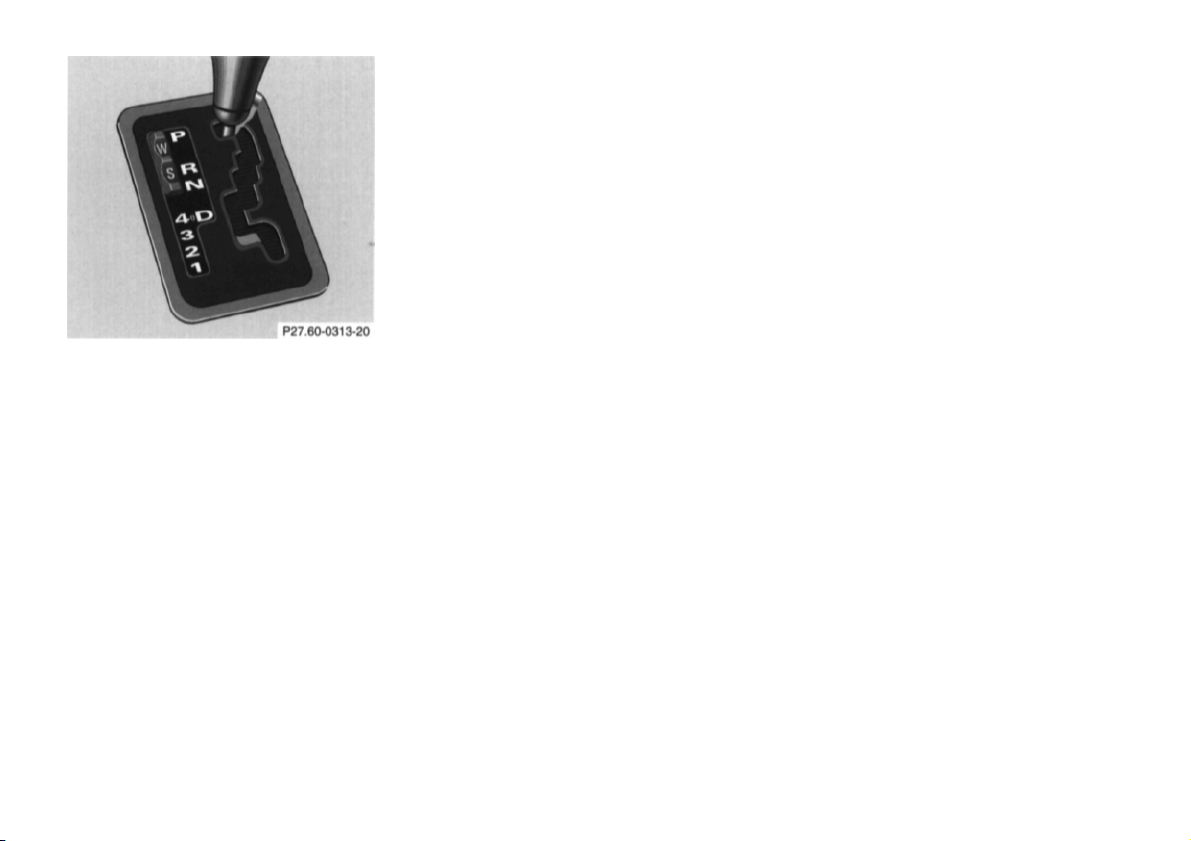
S Standard mode
in 1 st gear, or with
Press switch on symbol "S". Use
this mode for all regular driving.
The vehicle starts out in 1st
gear.
W Winter/Wet (snow and ice) mode
Emergency Operation
(Limp Home Mode)
If vehicle acceleration worsens, or the
transmission no longer shifts, the
transmission operates in Limp Home
Mode. In addition the "CHECK
ENGINE" malfunction indicator lamp in
the instrument cluster may come on.
Program Mode Selector Switch
The transmission is provided with a
selector switch for Standard "S" and
Winter/Wet (snow and ice) "W"
program modes.
Warning!
Always be certain of the program mode
selected since the vehicle driving
characteristics change with the
selection of the program mode.
Press switch on symbol "W". The
vehicle starts out in 2nd gear, except
with selector lever
accelerator pedal in kick-down
position.
The "W" mode helps to improve
traction and driving stability of the
vehicle.
With hard acceleration the upshifts
occur at lower vehicle and engine
speeds than in the "S" program mode.
Warning!
During stops use the brake, especially
on an incline, to prevent the vehicle
from rolling.
In this mode only the 2nd gear or
reverse gear can be activated.
To engage 2nd gear or reverse:
1. Stop the vehicle.
2. Move selector lever to
position "P".
3. Turn off the engine.
4. Wait 10 seconds.
5. Restart the engine.
6. Move selector lever to
position "D" (for 2nd gear), or
move selector lever to
position "R" (for reverse gear).
Have the transmission checked at your
authorized Mercedes-Benz dealer as
soon as possible.
76
Page 2
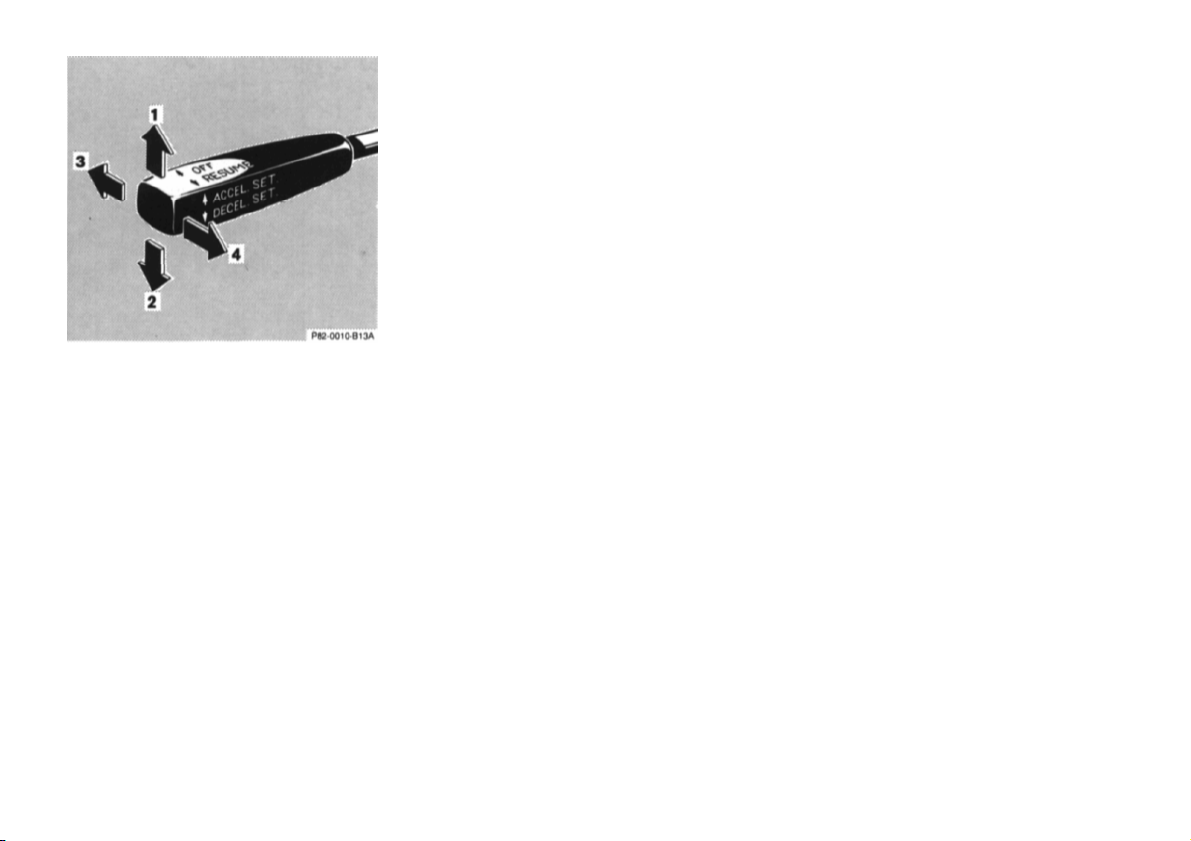
Cruise Control
maintained with the
Any given speed above approximately 25
mph (40 km/h) can be
cruise control by operating the lever.
1 Accelerate and set:
Lift lever briefly to set speed. Hold
lever up to accelerate.
2 Decelerate and set:
Depress lever briefly to set
speed.
Hold lever down to decelerate
Normally the vehicle is accelerated to
the desired speed with the accelerator.
Speed is set by briefly pushing the lever
to position 1 or 2. The accelerator can
be released.
The speed can be increased (e.g. for
passing) by using the accelerator. After
the accelerator is released, the
previously set speed will be resumed
automatically.
If a set speed is to be increased or
decreased slightly, e.g. to adapt to the
traffic flow, hold lever in position 1 or 2
until the desired speed is reached, or
briefly tip the lever in the appropriate
direction for increases or decreases in
0.6 mph (1 km/h) increments. When the
lever is released, the newly set speed
remains.
3 Canceling
To cancel the cruise control, briefly
push lever to position 3.
When you step on the brake pedal
or the vehicle speed drops below
approx. 25 mph (40 km/h), for
example when driving upgrade, the
cruise control will be canceled.
If the cruise control cancels by itself
and remains inoperative until the
engine is restarted, have the system
checked at your authorized
Mercedes-Benz dealer as soon as
possible.
4 Resume
If the lever is briefly pushed to
position 4 when driving at a speed
exceeding approx. 25 mph (40
km/h), the vehicle resumes the
speed which was set prior to the
cancellation of the cruise control.
The last memorized speed is
canceled when the electronic key in
the steering lock is turned to
position 1 or 0.
77
Page 3

Notes:
Important!
Warning!
If the engine does not brake the vehicle
sufficiently whiledriving on a downgrade,
the speed you set on the cruise control
may be exceeded and you may have to
step on the brake pedal to slow down. As
soon as the grade eases, the cruise
controlled speed will again be maintained
as long as the brakes were not previously
applied, or the lever may be used to resume the previously set speed if the
brakes were applied.
Moving gear selector lever to position
"N" switches the cruise control off.
Only use the cruise control if the
traffic and weather conditions make
it advisable to travel at a steady
speed.
• The use of cruise control can be
dangerous on winding roads or
in heavy traffic because
conditions do not allow safe
driving at a steady speed.
• The use of cruise control can be
dangerous on slippery roads.
Rapid changes in tire adhesion
can result in wheel spin and loss
of control.
The "Resume" function should only
be operated if the driver is fully
aware of the previously set speed and
wishes to resume this particular
preset speed.
78
Page 4

Multifunction Indicator
until the presently
Temporarily Switching Off
Charge Indicator
Language Selection
Warning message selection is available
in the English, French, German, Italian,
or Spanish language.
With the electronic key in steering lock
position 2, simultaneously press reset
buttons for Trip Odometer (O) and
Multifunction Indicator (R), located in
the instrument cluster,
selected language appears on the screen.
Press button O until the requested
language appears.
Turn the electronic key in steering lock
to position 0.
Multiple Malfunctions
When the multiple malfunction symbol
appears, this indicates that several
malfunction messages are stored in
memory.
Push reset button (R) in the instrument
cluster for subsequent messages.
To temporarily switch off the
multifunction indicator warning
symbol and message, push reset button
(R) in the instrument cluster.
The multifunction indicator display is
inoperative until the electronic key in
steering lock is turned again to position
0 or 2.
The symbols and messages for Parking
Brake, Seat Belts, Exterior Lights, and
Display Defective cannot be switched
off.
Defective
When the message "Display Defective"
appears, this indicates that the system
is not operational, and possibly other
warnings cannot be shown.
Have the vehicle electronic system
checked at your authorized MercedesBenz dealer as soon as possible.
When the symbol and message appear
while the engine is running, this
indicates a fault which must be
repaired at an authorized MercedesBenz dealer immediately.
It may indicate that the poly-V-belt has
broken. Should this condition occur,
the poly-V-belt must be replaced
before continuing to operate the
vehicle. Otherwise, the engine will
overheat due to an inoperative water
pump which may result in damage to
the engine.
Do not continue to drive the vehicle
with the charge indicator symbol
displayed. Doing so could result in
serious engine damage that is not
covered by the Mercedes-Benz Limited
Warranty.
79
Page 5

Low Engine Oil Level Warning
Engine Oil Consumption
Tachometer
When the symbol and message appear
while the engine is running and at
operating temperature, the engine oil
level has dropped to approximately the
minimum mark on the dipstick.
When this occurs, the warning will first
come on intermittently and then stay on
if the oil level drops further.
If no oil leaks are noted, continue to
drive to the nearest service station
where the engine oil should be topped
to the "full" mark on the dipstick with
an approved oil.
The low engine oil level warning
should not be ignored. Extended
driving with the symbol displayed
could result in serious engine damage
that is not covered by the MercedesBenz Limited Warranty.
In addition to the warning symbol, the
engine oil level should be periodically
checked with the dipstick or via the
multifunction indicator, for example
during a fuel stop, or before a long trip
(see Index).
Engine oil consumption checks should
only be made after the break-in period.
During the break-in period, higher oil
consumption may be noticed and is
normal. Frequent driving at high engine
speeds results in increased consumption.
Fuel Reserve Warning
When the symbol and message appear
after starting the engine, or if it comes
on while driving, it indicates that the
fuel level is down to the reserve
quantity of approximately: 2.6 gal (10
liters).
Red marking on tachometer:
Excessive engine speed.
Avoid this engine speed, as it may
result in serious engine damage that is
not covered by the Mercedes-Benz
Limited Warranty.
For engine protection, the fuel supply
is interrupted if the engine is operated
within the red marking.
80
Page 6

Outside Temperature Indicator
Coolant Temperature Gauge
Warning!
The temperature sensor is located in the
front bumper area. Due to its location,
the sensor can be affected by road or
engine heat during idling or slow
driving. This means that the accuracy of
the displayed temperature can only be
verified by comparison to a
thermometer placed next to the sensor,
not by comparison to external displays
(e.g. bank signs etc.).
Adaptation to ambient temperature takes
place in steps and depends on the
prevailing driving conditions (stop-andgo or moderate, constant driving) and
amount of temperature change.
Warning!
The outside temperature indicator is
not designed to serve as an IceWarning Device and is therefore unsuitable for that purpose. Indicated
temperatures just above the freezing
point do not guarantee that the road
surface is free of ice.
If the antifreeze mixture is effective to
-22°F (-30°C), the boiling point of the
coolant in the pressurized cooling
system of your vehicle is approx.
266°F (130°C).
During severe operating conditions and
stop-and-go city traffic, the coolant
temperature may rise close to the red
marking.
The engine should not be operated with
the coolant temperature in the red zone.
Doing so may cause serious engine
damage which is not covered by the
Mercedes-Benz Limited Warranty.
• Driving when your engine is
badly overheated can cause
some fluids which may have
leaked into the engine
compartment to catch fire. You
could be seriously burned.
• Steam from an overheated
engine can cause serious burns
and can occur just by opening
the engine hood. Stay away
from the engine if you see or
hear steam coming from it.
Turn off the engine, get out of the
vehicle and do not stand near the
vehicle until it cools down.
81
Page 7

Low Engine Coolant Level
Warning
When the symbol and message appear
while driving, then the coolant level
has dropped below the required level. If
no leaks are noticeable and the engine
temperature does not increase, continue
to drive to the nearest service station
and have coolant added to the coolant
system (see Index).
The low engine coolant level warning
should not be ignored. Extended
driving with the symbol displayed may
cause serious engine damage not
covered by the Mercedes-Benz Limited
Warranty.
In cases of major or frequent minor
coolant loss, have the cooling system
checked at your authorized MercedesBenz dealer as soon as possible.
Note:
Do not drive without coolant in the
cooling system. The engine will
overheat causing major engine damage.
Monitor the coolant temperature gauge
while driving.
Warning!
Do not spill antifreeze on hot engine
parts. Antifreeze contains ethylene
glycol which may burn if it comes
into contact with hot engine parts.
You can be seriously burned.
Low Windshield and Headlamp
Washer System Fluid Level Warning
When the symbol and message appear
while the engine is running, the level of
the reservoir has dropped to approx.1/
of the total volume. The reservoir
should be refilled with MB Windshield
Washer Concentrate "S" and water (or
commercially available premixed
windshield washer solvent/antifreeze,
depending on ambient temperature see Index) at the next opportunity. The
reservoir for the windshield and
headlamp washer systems is located in
the engine compartment.
3
82
Page 8

Exterior Lamp Failure Indicator
after starting the engine, or if it comes on
be certain to connect into the fuse before
Brake Pad Wear Indicator
Brake Warning
When the symbol and message appear
while driving, this symbol indicates a
failure in the parking lamp, taillamps,
stop lamp, or low beam headlamp.
If an exterior lamp fails, the indicator
symbol will come on only when that
lamp is switched on.
If a brake lamp fails, the lamp failure
indicator will come on when applying
the brake and stays on until the engine is
turned off.
Note:
If additional lighting equipment is
installed (e.g. auxiliary headlamps etc.)
the failure indicator monitoring unit in
order to avoid damaging the system.
When the symbol and message appear
during braking, this indicates that the
brake pads are worn down.
Have the brake system checked at your
authorized Mercedes-Benz dealer as
soon as possible.
When the brake warning lamp and
message appear while the engine is
running, this means:
• there is insufficient brake fluid in
the reservoir (engine running
and parking brake released), or
• the parking brake is set (engine
running).
Warning!
Driving with the brake warning
lamp illuminated can result in an
accident. Have your brake system
checked immediately if the brake
warning lamp stays on. Don't add
brake fluid before checking the
brake system. Overfilling the brake
fluid reservoir can result in spilling
brake fluid on hot engine parts and
the brake fluid catching fire. You
can be seriously burned.
Note:
If you find that the minimum mark on
the brake fluid reservoir is reached,
have the brake system checked for
brake pad thickness and leaks.
83
Page 9

Antilock Brake System (ABS)
electronic key in steering lock position 2
indicator lamps come on with the engine
ABS Control
Warning!
Important!
The ABS improves steering control of
the vehicle during braking maneuvers.
Do not pump the brake pedal, rather
use firm, steady brake pedal pressure.
Pumping the brake pedal defeats the
purpose for ABS and significantly
reduces braking effectiveness.
The ABS prevents the wheels from
locking up above a vehicle speed of
approximately 5 mph (8 km/h)
independent of road surface conditions.
At the instant one of the wheels is
about to lock up, a slight pulsation can
be felt in the brake pedal, indicating
that the ABS is in the regulating mode.
Keep firm and steady pressure on the
brake pedal while experiencing the
pulsation.
On slippery road surfaces, the ABS will
respond even with light brake pedal
pressure because of the increased
likelihood of locking wheels. The
pulsating brake pedal can be an
indication of hazardous road conditions
and functions as a reminder to take
extra care while driving.
The ABS malfunction indicator lamp in
the instrument cluster comes on with the
and should go out with the engine
running.
When the ABS malfunction indicator
lamp symbol and warning in the
instrument cluster come on while the
engine is running, it indicates that the
ABS has detected a malfunction and has
switched off. In this case, the brake
system functions in the usual manner,
but without antilock assistance.
With the ABS malfunctioning, the BAS,
ASR or ESP, if vehicle so equipped, are
also switched off. Both malfunction
running.
If the charging voltage falls below 10
volts, the malfunction indicator lamp
comes on and the ABS is switched off.
When the voltage is above this value
again, the malfunction indicator lamp
should go out and the ABS should be
operational.
Have the system checked at your
authorized Mercedes-Benz dealer as
soon as possible.
ABS cannot prevent the natural laws
of physics from acting on the vehicle,
nor can it increase the traction made
available by the road conditions. The
ABS cannot prevent accidents,
including those resulting from
excessive speed in turns, following
another vehicle too closely, or
aquaplaning. Only a safe, attentive,
and skillful driver can prevent
accidents. The capabilities of an ABS
equipped vehicle must never be
exploited in a reckless or dangerous
manner which could jeopardize the
user's safety or the safety of others.
Note:
To alert following vehicles to slippery
road conditions you discover, operate
your hazard warning flashers as
appropriate.
84
Page 10

Electronic Traction System (ETS)
ETS Control
Caution!
The ETS improves vehicle traction,
especially under slippery road
conditions. It engages at vehicle speeds
up to approximately 24 mph (40 km/h),
and applies the brakes to the spinning
drive wheel. At approximately 50 mph
(80 km/h), the ETS switches off.
The ETS warning lamp, located in the
speedometer dial, starts to flash at any
vehicle speed, as soon as the tires lose
traction and the wheels begin to spin.
Important!
If the ETS warning lamp flashes:
• during take-off, apply as little
throttle as possible,
• while driving, ease up on the
accelerator.
Adapt your speed and driving to the
prevailing road conditions.
If the yellow ETS malfunction
indicator lamp comes on while the ETS
warning symbol flashes, with the
engine running, the electronic traction
system is being switched off
temporarily to prevent overheating of
the drive wheel brakes.
If the ETS malfunction indicator lamp
comes on with the engine running, a
malfunction has been detected.
Have the ETS checked at your
authorized Mercedes-Benz dealer as
soon as possible.
With the ABS malfunctioning, the ETS
is also switched off.
If the vehicle is towed with the front
axle raised (see Towing the vehicle in
Index), or when testing the parking
brake on a brake test dynamometer, the
engine must be shut off. Otherwise, the
electronic traction system will
immediately be engaged and will apply
the rear wheel brakes.
Note:
In winter operation, the maximum
effectiveness of the electronic traction
system is only achieved with
Mercedes-Benz recommended M+S
radial-ply tires and/or snow chains.
85
Page 11

Acceleration Slip Regulation (ASR)
The acceleration slip regulation will
engage at all vehicle speeds, if one or
both drive wheels begin to lose traction
and spin due to excessive acceleration.
While engaged, the yellow warning
lamp in the speedometer flashes.
With the acceleration slip regulation
engaged, the brake is applied to the
spinning drive wheel until it regains
sufficient traction. If both drive wheels
lose traction and spin, the brake is
applied to both drive wheels and
simultaneously, engine torque is
limited, to improve the vehicle's
driving stability.
As traction on the road surface
increases, the allowable engine torque
also increases again and the brake is no
longer applied to drive wheels.
Important!
If the ASR warning lamp flashes, adapt
your speed and driving to the
prevailing road conditions.
Caution!
If the vehicle is towed with the front
axle raised (see Towing the vehicle in
Index), the engine must be shut off.
Otherwise, the acceleration slip
regulation will immediately be engaged
and will apply the rear wheel brakes.
Notes:
If the ASR malfunction indicator lamp
comes on with the engine running, a
malfunction has been detected.
Pressing the accelerator pedal will
require greater effort. Only partial
engine output is available.
Have the ASR checked at your
authorized Mercedes-Benz dealer as
soon as possible.
With the ABS malfunctioning, the
ASR is also switched off.
Driving the vehicle with varied size
tires will cause the wheels to rotate at
different speeds, therefore the
acceleration slip regulation may
activate (yellow ASR warning lamp in
instrument cluster comes on). For this
reason, all wheels, including the spare
wheel, must have the same tire size.
When testing the parking brake on a
brake test dynamometer, the engine
must be shut off. Otherwise, the
acceleration slip regulation will
immediately be engaged and will apply
the rear wheel brakes.
In winter operation, the maximum
effectiveness of the acceleration slip
regulation is only achieved with
Mercedes-Benz recommended M+S
radial-ply tires and/or snow chains.
86
Page 12
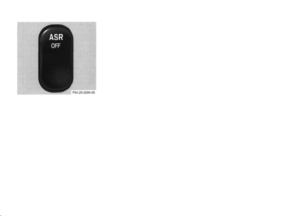
ASR Control Switch
ASR control switch located on center
console
The ASR warning lamp, located in the
speedometer dial, starts to flash at any
vehicle speed as soon as the tires lose
traction and the wheels begin to spin.
ASR control switch located in center
console
To improve the vehicle's traction when
driving with snow chains, or starting
off in deep snow, sand or gravel, press
the upper half of the ASR switch. The
ASR warning lamp, located in the
speedometer dial, is continuously
illuminated.
With the ASR system switched off, the
engine torque reduction feature is
cancelled. Therefore, the enhanced
vehicle stability offered by ASR is
unavailable.
Adapt your speed and driving to the
prevailing road conditions.
A portion of the ASR system remains
active, even with the switch in the OFF
position.
If one drive wheel loses traction and
begins to spin, the brake is applied
until the wheel regains sufficient
traction. The traction control engages
at vehicle speeds up to approximately
24 mph (40 km/h), and switches off at
50 mph (80 km/h).
To return to the enhanced vehicle
stability offered by ASR: press lower
half of the switch (the ASR warning
lamp in the speedometer dial goes out).
Important!
If the ASR warning lamp flashes:
• during take-off, apply as little
throttle as possible,
• while driving, ease up on the
accelerator.
87
Page 13

Electronic Stability Program
(ESP) Model E 420 (optional)
The ESP enhances directional control
and reduces driving wheel spin of the
vehicle under any driving condition.
Over/understeering of the vehicle is
counteracted by applying brakes to the
appropriate wheel to create a
counterpointing vehicle movement.
The ESP warning lamp, located in the
speedometer dial, starts to flash.
Important!
If the ESP warning lamp flashes, adapt
your speed and driving to the
prevailing road conditions.
Caution!
If the vehicle is towed with the front
axle raised (see Towing the vehicle in
Index), the engine must be shut off
(electronic key in steering lock position
0 or 1). Otherwise, the ESP will
immediately be engaged and will apply
the rear wheel brakes.
Notes:
If the ESP malfunction indicator lamp
comes on with the engine running, a
malfunction has been detected. It is
possible that now only partial engine
output is available.
Have the ESP checked at your
authorized Mercedes-Benz dealer as
soon as possible.
With the ABS malfunctioning, the ESP is
also switched off.
Driving the vehicle with varied size
tires will cause the wheels to rotate at
different speeds, therefore the ESP may
activate (yellow ESP warning lamp in
speedometer dial comes on). For this
reason, all wheels, including the spare
wheel, must have the same tire size.
When testing the parking brake on a
brake test dynamometer, the engine
must be shut off. Otherwise, the ESP
will immediately be engaged and will
apply the rear wheel brakes.
In winter operation, the maximum
effectiveness of the ESP is only
achieved with Mercedes-Benz
recommended M+S rated radial-ply
tires and/or snow chains.
88
Page 14
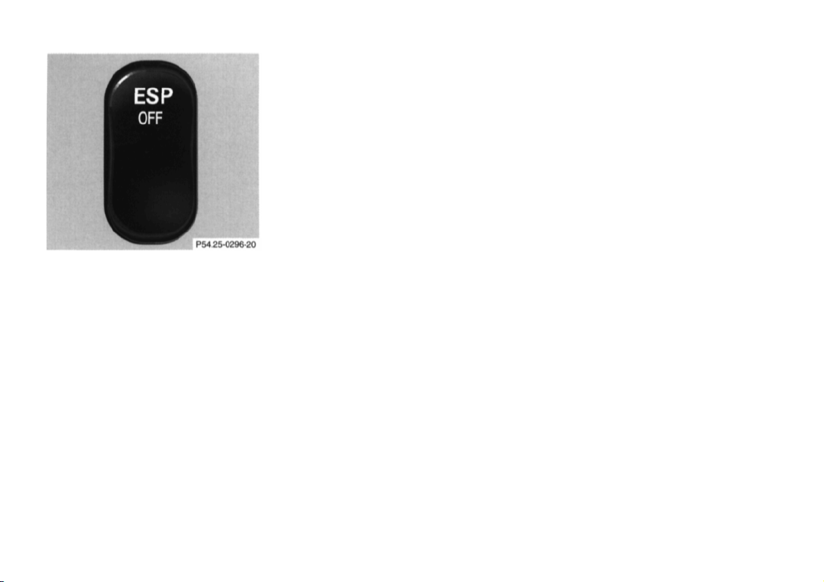
ESP control switch located on center
console
ESP Control Switch
To improve the vehicle's traction when
driving with snow chains, or starling
off in deep snow, sand or gravel, press
the upper half of the ESP switch. The
ESP warning lamp, located in the
speedometer dial, is continuously
illuminated.
With the ESP system switched off, the
engine torque reduction feature is
cancelled. Therefore, the enhanced
vehicle stability offered by ESP is
unavailable.
Adapt your speed and driving to the
prevailing road conditions.
A portion of the ESP system remains
active, even with the switch in the OFF
position.
If one drive wheel loses traction and
begins to spin, the brake is applied
until the wheel regains sufficient
traction. The traction control engages
at vehicle speeds up to approximately
24 mph (40 km/h), and switches off at
50 mph (80 km/h).
The ESP warning lamp, located in the
speedometer dial, starts to flash at any
vehicle speed as soon as the tires lose
traction and the wheels begin to spin.
To return to the enhanced vehicle
stability offered by ESP: press lower
half of the switch (the ESP warning
lamp in the speedometer dial goes out).
Important!
If the ESP warning lamp flashes:
• during take-off, apply as little
throttle as possible,
• while driving, ease up on the
accelerator.
89
Page 15

Emission Control
Warning!
Vehicles with gasoline engine
Certain systems of the engine serve to
keep the toxic components of the
exhaust gases within permissible limits
required by law.
These systems, of course, will function
properly only when maintained strictly
according to factory specifications.
Any adjustments on the engine should,
therefore, be carried out only by
qualified Mercedes-Benz authorized
dealer technicians. Engine adjustments
should not be altered in any way.
Moreover, the specified service jobs
must be carried out regularly according
to Mercedes-Benz servicing
requirements. For details refer to the
Service Booklet.
Inhalation of exhaust gas is
hazardous to your health. All
exhaust gas contains carbon
monoxide, and inhaling it can cause
unconsciousness and lead to death.
Do not run the engine in confined
areas (such as a garage) which are
not properly ventilated. If you think
that exhaust gas fumes are entering
the vehicle while driving, have the
cause determined and corrected
immediately. If you must drive
under these conditions, drive only
with at least one window fully open.
On-Board Diagnostic System
Vehicles with Diesel engine
Whenthe "CHECK ENGINE" malfunction indicator lamp comes on while
the engine is running, this indicates a
malfunction in the fuel injection system.
Only partial engine output is available.
Have the system checked at your
authorized Mercedes-Benz dealer as
soon as possible.
The Sequential Multiport Fuel
Injection (SFI) control module
monitors emission control components
that either provide input signals to or
receive output signals from the control
module. Malfunctions resulting from
interruptions or failure of any of these
components are indicated by the
"CHECK ENGINE" malfunction
indicator lamp in the instrument cluster
and are simultaneously stored in the
diagnostic module.
If the "CHECK ENGINE" malfunction
indicator lamp comes on, have the
system checked at your authorized
Mercedes-Benz dealer as soon as
possible.
An on-board diagnostic connector is
located in the passenger compartment
near to the parking brake pedal,
allowing the accurate identification of
system malfunctions through the
readout of diagnostic trouble codes.
90
Page 16

Winter Driving
Have your vehicle winterized at your
authorized Mercedes-Benz dealer
before the onset of winter.
• Change the engine oil if the engine
contains an oil which is not
approved for winter operation. For
viscosity (SAE/CCMC class) and
filling quantity, see Capacities:
Fuels, Coolants, Lubricants etc. in
Index.
• Test battery: Battery capacity
drops with decreasing ambient
temperature. A well charged
battery helps to ensure that the
engine can be started, even at low
ambient temperatures.
• Tires: We recommend M+S rated
radial-ply tires on all four wheels
for the winter season. Observe
permissible maximum speed for
M+S rated radial-ply tires and the
legal speed limit.
Vehicles with diesel engine –
• For diesel fuels, refer to Index.
• Engine block heater:
The engine is equipped with a
block heater. The electrical cable
may be installed free-of-charge at
your authorized Mercedes-Benz
dealer by using the coupon in the
"Owner's Service and Warranty
Policy" booklet. The coupon is valid
for 12 months from date of vehicle
delivery.
• Check engine coolant anticorrosion/
antifreeze concentration.
• Additive for the windshield washer
and headlamp cleaning system: Add
MB Concentrate "S" to a premixed
windshield washer solvent/
antifreeze which is formulated for
below freezing temperatures (see
Index).
Note:
In winter operation, the maximum
effectiveness of the acceleration slip
regulation or of the electronic traction
system can only be achieved with M+S
radial-ply tires and/or snow chains
recommended by Mercedes-Benz.
Snow chains maximize performance.
91
Page 17

Snow Chains
Use only snow chains that are tested
and recommended by Mercedes-Benz.
Your authorized Mercedes-Benz dealer
will be glad to advise you on this
subject.
Chains should only be used on the rear
wheels. Follow the manufacturer's
mounting instructions.
Snow chains should only be driven on
snow covered roads at speeds not to
exceed 30 mph (50 km/h). Remove
chains as soon as possible when
driving on roads without snow.
For tips on driving on slippery winter
roads, refer to Index.
Vehicles with Acceleration Slip
Regulation (ASR) or Electronic
Stability Program (ESP):
When driving with snow chains, press
the ASR control switch or the ESP
control switch, refer to Index.
Vehicles with Sport Package
Use of snow chains in not permissible
with tire size 235/45 ZR 17.
Traveling Abroad
Abroad, there is a widely-spread
Mercedes-Benz service network at
your disposal. If you plan to travel into
areas which are not listed in the index
of your dealer directory, you should
request pertinent information from
your authorized Mercedes-Benz dealer.
92
Page 18

Practical Hints
93
Page 19
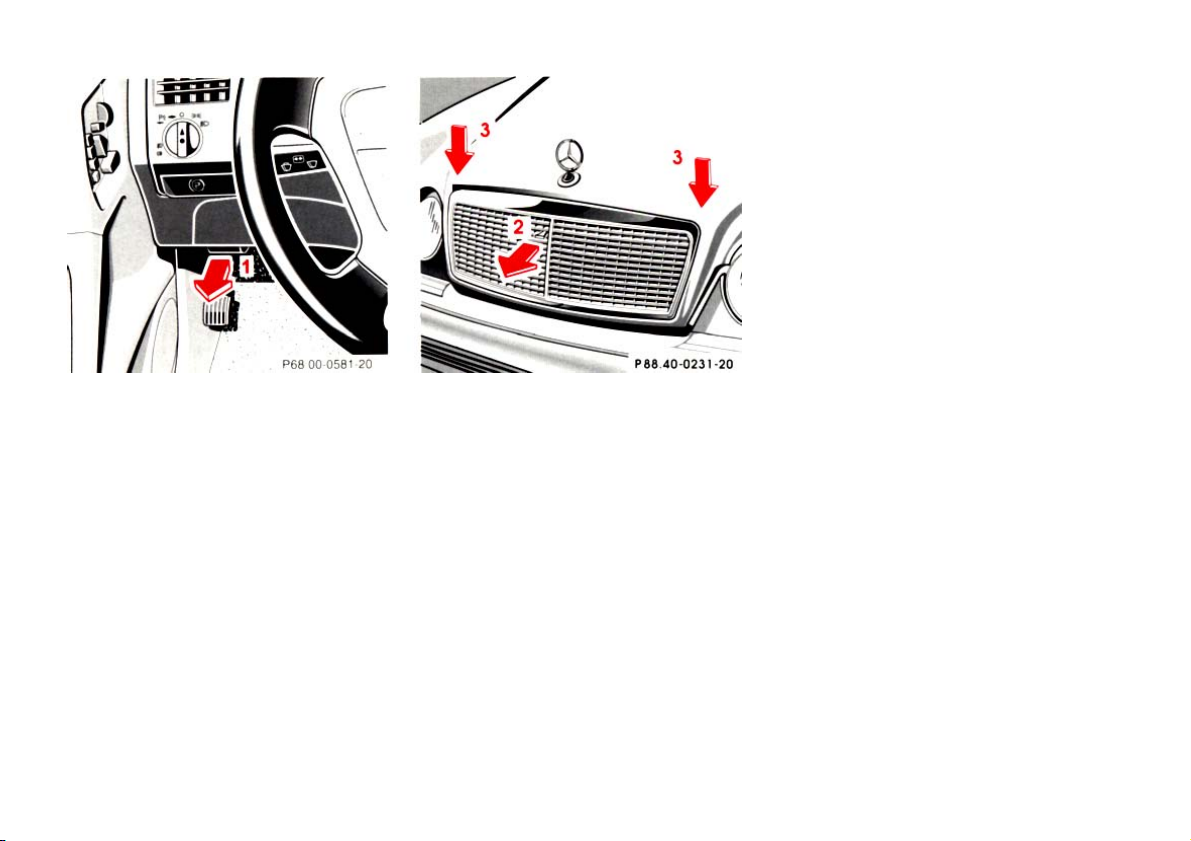
Hood
To open:
To unlock the hood, pull release lever
(1) under the driver's side of the
instrument panel. At the same time
handle (2) will extend out of the
radiator grill (it may be necessary to lift
the hood up slightly).
Pull handle (2) completely out of
radiator grill and open hood (do not
pull upon handle).
To close:
Lower hood and let it drop into lock
from a height of approx. 1 ft. (30 cm),
assisting with hands placed flat on
edges of hood (3).
Warning!
To help prevent personal injury, stay
clear of moving parts when the hood
is open and the engine is running. Be
sure the hood is properly closed
before driving. When closing hood,
use extreme caution not to catch
hands or fingers.
Warning!
Vehicles with gasoline engine:
The engine is equipped with a
transistorized ignition system.
Because of the high voltage it is
dangerous to touch any components
(ignition coils, spark plug sockets,
ignition cables, diagnostic socket)
of the ignition system
• with the engine running,
• while starting the engine,
• if ignition is "on" and the engine
is turned manually.
Caution!
To avoid damage to the windshield
wiper or hood, open the hood only with
wiper in the parked position.
To avoid hood damage, if hood is not
fully closed, repeat closing procedure.
Do not push down on hood to attempt to
fully close it.
94
Page 20
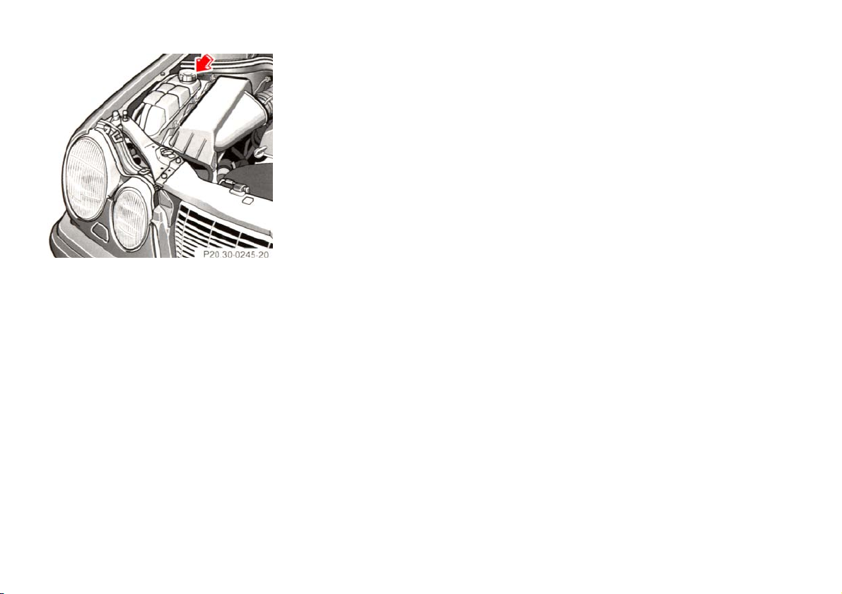
Adding Coolant
Warning!
Checking Coolant Level
To check the coolant level, the vehicle
must be parked on level ground and
the engine stopped.
Check coolant level only when coolant
is cold.
If coolant has to be added, a 50/50
mixture of water and MB
anticorrosion/antifreeze should be
added.
The drain plugs for the cooling system
are located on the right side of the
engine block and at the bottom of the
radiator.
Anticorrosion/antifreeze, see
Coolants in Index.
In order to avoid possible serious
burns or injury:
• Use extreme caution when
opening the hood if there are any
signs of steam or coolant leaking
from the cooling system, or if the
coolant temperature gauge
indicates that the coolant is
overheated.
• Do not remove pressure cap on
coolant reservoir if engine
temperature is above 194°F(90°C).
Allow engine to cool down before
removing cap. The coolant
reservoir contains hot fluid and is
under pressure.
• Using a rag, slowly open cap
approximately1/2turn to relieve
excess pressure. If opened
immediately, scalding hot fluid
and steam will be blown out
under pressure.
• Do not spill antifreeze on hot
engine parts. Antifreeze contains
etnylene glycol which may burn if
it comes into contact with hot
engine parts.
95
Page 21
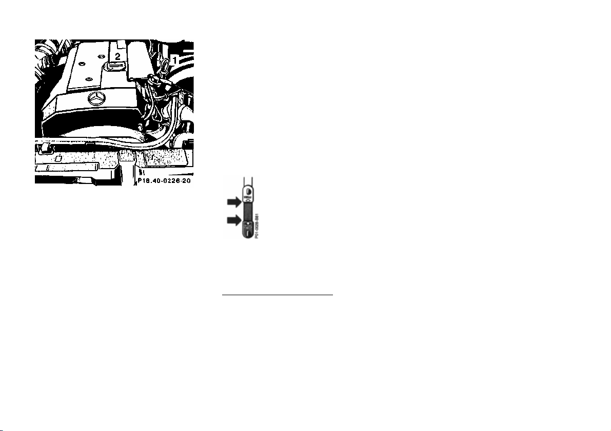
Checking Engine Oil Level
rument
1 Oil dipstick
2 Oil filler cap
The engine oil level can be checked by
either the oil dipstick or via the
multifunction indicator in the inst
cluster.
To check the engine oil level, park
vehicle on level ground, with engine at
normal operational temperature.
Check engine oil level approximately 5
minutes after stopping the engine,
allowing for the oil to return to the oil
pan.
Oil level must be between
the lower (min) and upper
(max) mark of the dipstick.
Fill quantity between upper and lower
dipstick marking level is approximately
2.1 US qt (2.0 l).
Do not overfill the engine. Excessive
oil must be drained or siphoned. It
could cause damage to engine and
catalytic converter not covered by the
Mercedes-Benz Limited Warranty.
Bleeding of Diesel Fuel System
If the engine ran out of fuel, the fuel
system has to be purged of air after
refilling the tank.
Turn the key in steering lock fully to the
right and crank engine (for up to 40
seconds maximum). Only release key
after engine fires evenly.
Automatic Transmission Fluid Level
The transmission has a permanent fill
of automatic transmission fluid.
Regular automatic transmission fluid
level checks and changes are not
required. For this reason the dipstick is
omitted.
When noticing fluid loss or gear
shifting malfunctions, have your
authorized Mercedes-Benz dealer
check the transmission fluid level.
For Low engine oil level warning, see
Index.
96
Page 22
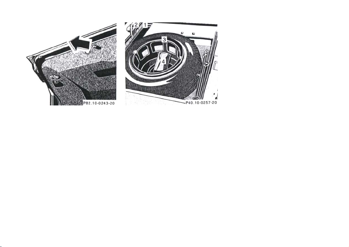
To remove spare tire: Turn luggage
bowl counterclockwise and remove.
To store spare tire: Place spare tire in
wheel well and secure it with luggage
bowl. Turn luggage bowl clockwise to
its stop.
Note:
Always lower trunk floor before
closing trunk lid.
Stowing Things in the Vehicle
Trunk Lamp
If the trunk is to remain open for a long
period of time, the trunk lamp can be
switched off by pulling out the plunger
in the switch (arrow). This prevents the
vehicle battery from being discharged.
When the trunk lid is closed, the switch
will reset and turn on the lamp next
time the lid is opened.
Spare Wheel, Vehicle Tools, Storage
Compartment
1 Trunk floor
2 Handle
3 Luggage bowl
4 Vehicle tools
Lift trunk floor and engage handle in
upper edge of the trunk.
Warning!
To help avoid personal injury during
a collision or sudden maneuver,
exercise care when stowing things.
Put luggage or cargo in the trunk if
possible. Do not pile luggage or
cargo higher than the seat backs. Do
not place anything on the shelf below
the rear window.
97
Page 23
Warning!
Wheels
Vehicle Jack
1 Jack arm
2 Jack base
The vehicle jack is stored behind the
spare wheel.
See illustration for proper storage ofjack.
To remove, first remove vehicle tools and
spare wheel. Then open clamp and
remove vehicle jack.
Before storing the jack in the spare wheel
well, the jack arm must be lowered
almost to the base of the jack.
The jack is designed exclusively for
jacking up the vehicle at the jack
tubes built into either side of the
vehicle. To help avoid personal
injury, use the jack only to lift the
vehicle during a wheel change. Never
get beneath the vehicle while it is
supported by the jack. Keep hands
and feet away from the area under
the lifted vehicle. Always firmly set
parking brake and block wheels
before raising vehicle with jack.
Do not disengage parking brake
while the vehicle is raised. Be certain
that the jack is always vertical when
in use, especially on hills. Always try
to use the jack on level surface. Be
sure that the jack arm is fully
inserted in the jack tube. Always
lower the vehicle onto sufficient
capacity jackstands before working
under the vehicle.
Replace rims or tires with the same
designation, manufacturer and type as
shown on the original part. See your
authorized Mercedes-Benz dealer for
further information.
Warning!
Do not mix different tire construction
types (i.e. radial, bias, and bias-belted)
on your car because handling may be
adversely affected and may result in
loss of control.
See your authorized Mercedes-Benz
dealer for information on tested and
recommended rims and tires for
summer and winter operation. They
can also offer advice concerning tire
service and purchase.
98
Page 24

Tire Replacement
Warning!
Important!
Front tires should be replaced in sets.
Furthermore - in the event of tire
replacement - the spare wheel (except
model E 420 with Sport Package), if
possible, should be used on the rear
axle. Rims and tires must be of the
correct size and type. For dimensions,
see "Technical Data".
We recommend that you break in new
tires for approx. 60 miles (100 km) at
moderate speed.
It is imperative that the wheel mounting
bolts be retightened after approximately
60-300 miles (100-500 km) whenever
wheels are fitted, e.g. when the spare
wheel is used for the first time or when a
set of wheels with M+S tires is installed.
Tightening torque:
80 ft.lb. (110 Nm).
For rim and tire specifications, refer to
"Technical Data".
Worn, old tires can cause accidents.
If the tire tread is badly worn, or if
the tires have sustained damage,
replace them.
When replacing rims, use only
genuine Mercedes-Benz wheel bolts
specified for the particular rim
type. Failure to do so can result in
the bolts loosening and possibly an
accident.
Rotating Wheels
The wheels can be rotated according to
the degree of tire wear while retaining
the same direction of travel.
Rotating, however, should be carried
out at the scheduled service intervals,
before the characteristic tire wear
pattern (shoulder wear on front wheels
and tread center wear on rear wheels)
becomes visible, as otherwise the
driving properties deteriorate.
Unidirectional tires must always be
mounted with arrow on tire sidewall
pointing in direction of vehicle forward
movement.
Notes:
Thoroughly clean the inner side of the
wheels any time you rotate the wheels
or wash the vehicle underside.
The use of retread tires is not
recommended. Retread tires may
adversely affect the handling
characteristics and safety of the vehicle.
Dented or bent rims can cause tire
pressure loss and damage to the tire
beads. For this reason, check rims for
damage at regular intervals. The rim
flanges must be checked for wear
before a tire is mounted. Remove burrs,
if any.
Check and ensure proper tire inflation
pressure after rotating the wheels. For
Tire Inflation Pressure refer to Index.
99
Page 25

Warning!
le. To help avoid personal injury,
and feet away from the area under the
the jack is always vertical when in use,
Spare Wheel for Sport Package
The jack is designed exclusively for
jacking up the vehicle at the jack
tubes built into either side of the
vehic
use the jack only to lift the vehicle
during a wheel change. Never get
beneath the vehicle while it is
supported by the jack. Keep hands
lifted vehicle. Always firmly set
parking brake and block wheels
before raising vehicle with jack.
Do not disengage parking brake while
the vehicle is raised. Be certain that
especially on hills. Always try to use
the jack on level surface. Be sure that
the jack arm is fully inserted in the
jack tube. Always lower the vehicle
onto sufficient capacity jackstands
before working under the vehicle.
The spare wheel rim size is 71/2Jx16 H
2 with tire size 215/55 R 16 93 H.
In the case of a flat tire or breakdown,
you may temporarily use a 71/2J x 16 H
2 instead of the 8 J x 16 H 2 wheel rim
on the rear axle, when observing the
following restrictions:
• Do not exceed vehicle speed of
50 mph (80 km/h).
• Drive to the nearest repair
facility.
For additional information, refer to
"Technical Data".
Changing Wheels
Move vehicle to a level area which is a
safe distance from the roadway.
1. Set parking brake and turn on
hazard warning flasher.
2. Move selector lever to position
"P" and turn off engine.
3. Prevent vehicle from rolling
away by blocking wheels with
wheel chocks (not supplied with
vehicle) or sizable wood block
or stone. When changing a
wheel on a hill, place chocks on
the downhill side blocking both
wheels of the other axle. On a
level road, place one chock in
front of and one behind the
wheel that is diagonally opposite
to the wheel being changed.
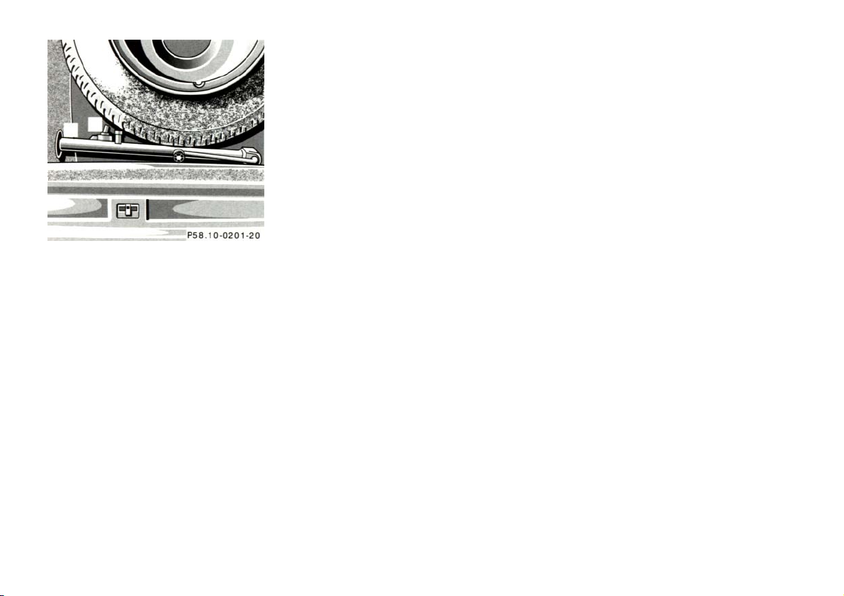
4. Using the wrench, loosen but do
not yet remove the wheel bolts.
100
Page 26

5. Remove the protective cover from
the jack support tube opening by
inserting the screwdriver (supplied
in the tool kit) in the opening and
prying it out.
The tube openings are located
directly behind the front wheel
housings and in front of the rear
wheel housings.
6. Insert jack arm fully into the tube
hole up to the stop. Place jack
on firm ground. Position the jack
so that it is always vertical
(plumb-line) as seen from the
side (see arrow), even if the
vehicle is parked on an incline.
7. Jack up the vehicle until the
wheel is clear of the ground.
Never start engine while vehicle
is raised.
8. Unscrew upper-most wheel bolt
and install alignment bolt (1)
supplied in the tool kit. Remove
the remaining bolts. Keep bolt
threads protected from dirt and
sand.
9. Remove wheel. Grip wheel from
the sides. Keep hands from
beneath the wheels.
101
Page 27

10. Clean contact surfaces of
wheel and wheel hub. Install
spare wheel on wheel hub.
Insert wheel bolts and tighten
them slightly.
To avoid paint damage, place
wheel flat against hub and hold it
there while installing first wheel
bolt.
Unscrew the alignment bolt (1) to
install the last wheel bolt.
11. Lower car. Remove jack and
insert jack tube cover.
Before storing the jack, the jack arm
must be lowered almost to the base of
the jack.
Warning!
Always replace wheel bolts that are
damaged or rusted.
Never apply oil or grease to wheel
bolts.
Damaged wheel hub threads should
be repaired immediately.
Incorrect mounting bolts or
improperly tightened mounting bolts
can cause the wheel to come off. This
could cause an accident. Be sure to
use the correct mounting bolts.
12. Using the wrench, tighten the
five bolts evenly, following the
sequence illustrated, until all
bolts are tight.
Observe a tightening torque of
80 ft.lb. (110 Nm).
13. Ensure proper tire pressure.
Important!
When installing new wheels the
mounting bolts must be retightened
after approx. 60 - 300 miles (100 to
500 km).
102
Page 28

Tire Inflation Pressure
A table (see fuel filler flap) lists the tire
inflation pressures specified for
Mercedes-Benz recommended tires as
well as for the varying operating
conditions.
Important!
Tire pressure changes by approx. 1.5
psi (0.1 bar) per 18°F (10°C) of air
temperature change. Keep this in mind
when checking tire pressure inside a
garage - especially in the winter.
Example:
If garage temperature = approx. +68°F
(+20°C) and ambient temperature =
approx. +32°F (0°C) then the adjusted
air pressure = specified air pressure +3
psi (+0.2 bar).
Tire pressures listed for light loads are
minimum values offering high driving
comfort. Increased inflation pressures
for heavy loads produce favorable
handling characteristics with lighter
loads and are perfectly permissible.
The ride of the vehicle, however, will
become somewhat harder.
Tire temperature and pressure
increase with the vehicle speed. Tire
pressure should therefore only be
corrected on cold tires. Correct tire
pressure in warm tires only if pressure
has dropped below the pressure listed
in the table and the respective
operating conditions are taken into
consideration.
An underinflated tire due to a slow
leak (e.g. due to a nail in the tire) may
cause damage such as tread
separation, bulging etc.. Regular tire
pressure checks (including the spare
tire) at intervals of no more than 14
days are therefore essential.
If a tire constantly loses air, it should
be inspected for damage.
Warning!
Do not overinflate tires.
Overinflating tires can result in
sudden deflation (blowout) because
they are more likely to become
punctured or damaged by road
debris, potholes etc.. Follow recommended inflation pressures.
Do not overload the tires by
exceeding the specified vehicle
capacity weight (as indicated by the
label on the driver's door latch post).
Overloading the tires can overheat
them, possibly causing a blowout.
103
Page 29

3 Clamps for headlamp cover
4 Bulb socket for turn signal lamp
5 Electrical connector for low
beam headlamp bulb
6 Electrical connector for high
beam headlamp bulb
Xenon lamp (optional) ignition
module for low beam
7 Bulb socket for parking and
standing lamp
8 Level for headlamp vertical
adjustment
Exterior Lamps
Headlamp Adjustment
Correct headlamp adjustment is
extremely important. Check and
readjust headlamps at regular intervals
and when a bulb has been replaced.
Headlamp Assembly
1 Headlamp horizontal adjustment
screw
2 Headlamp vertical adjustment
screw
104
Page 30

Replacing Bulb:
When replacing bulbs, install only 12
volt bulbs with the specified watt
rating.
When replacing halogen bulbs do not
touch glass portion of bulb with bare
hands. Use plain paper or a clean cloth.
Warning!
Halogen lamps contain pressurized
gas. A bulb can explode if you:
• touch or move it when hot,
• drop the bulb,
• scratch the bulb.
Wear eye and hand protection.
Bulbs for Low or High Beam
H7 (55 W)
Open hood.
Move retaining clamps (3) aside and
remove cover. Pull off electrical
connector (5) or (6). Unhook clamping
ring and pull out bulb together with
clamping ring. Remove bulb.
Insert new bulb (seating properly in
cutouts of bulb socket), mount clamping
ring. Reinstall and push electrical
connector on securely. Reinstall cover
and fasten with retaining clamps (3).
Xenon (optional)
Bulb for Low Beam
Warning!
Because of high voltage in Xenon
lamps, it is dangerous to replace the
bulb or repair the lamp and its
components. We recommend that
you have such work done by a
qualified technician.
Turn Signal Lamp
1156 NA (26.9/5 W/32/4 cp bulb)
Open hood.
Twist bulb socket (4) counterclockwise
and pull out. Push bulb into socket,
turn counterclockwise and remove.
Insert new bulb in socket, push in and
twist clockwise. Reinstall bulb socket.
Reinstall lamp assembly until properly
seated.
Parking and Standing Lamp
H 6W (6 W bulb)
Open hood.
Rotate cover (3) counterclockwise and
remove.
Twist bulb socket (7) counterclockwise
and pull out. Push bulb into socket,
turn counterclockwise and remove.
Insert new bulb in socket, push in and
twist clockwise. Reinstall bulb socket.
Reinstall lamp assembly until properly
seated.
105
Page 31

3. Move vehicle on the level
surface 25 feet (7.6 m) straight
back from the wall.
4. Open hood.
5. Vertical headlamp aim
(low beams on):
Turn adjusting screw (2) (counterclockwise to adjust headlamp
downward, clockwise upward) until
bubble in the level (8) is centered
on the "O" mark.
Graduations: 0.18° pitch.
Adjusting Headlamp
Correct headlamp adjustment is
extremely important. To check and
readjust a headlamp, follow steps 1
through 7. Please note:
• Low beam adjustments
simultaneously aim the high beam.
• Vehicle should have a normal trunk
load.
• Vertical aim adjustments change
horizontal aim.
1. Park vehicle on level surface approx.
6 inches (152 mm) from a vertical
test screen or wall. The centerline of
the vehicle must be at a 90° angle to
the test screen.
2. Using a "T" square and a carpenter's
level, align and mark a vertical
centerline (8) on the test screen using
the outer reference point (low beam)
as found on each headlamp lens.
As a check, the distance between
centerlines should be 491/4inches
(1250 mm).
106
Page 32

6. Horizontal headlamp aim
(low beams on):
Turn adjusting screw (1)
(counterclockwise to adjust to
the left, clockwise to the right)
until the headlamps (low beam)
illuminate the test screen as
shown. The vertex of the angle
formed in each beam image
should align with the vertical
centerline (11) of each lamp.
The left and right headlamps must be
adjusted individually
7. The "O" on the indicator wheel
(9) should align with projection
(10). If it does not, with a small
screwdriver, pry indicator wheel
up and rotate so that the "O"
aligns with projection (1). Push
down indicator wheel until it
snaps in place.
Graduations: 0.38° pitch.
107
Page 33

Taillamp Assemblies
Open trunk lid.
1 Turn signal lamp
(21 W/32 cp bulb)
2 Stop, tail and parking lamp
(21/4 W/35/1.2 cp bulb)
3 Tail, parking and side marker lamp
(5 W/4 cp bulb)
Swing cover aside. Twist bulb socket
counterclockwise and pull out. Push
bulb into socket, turn counterclockwise
and remove.
Insert new bulb in socket, push in and
twist clockweise. Reinstall bulb socket,
and close cover
4 Driver's side:
Rear fog lamp
(21 W/32 cp bulb)
5 Backup lamp
(21 W/32 cp bulb)
Twist bulb socket counterclockwise and
pull out. Push bulb into socket, turn
counterclockwise and remove.
Insert new bulb in socket, push in and
twist clockwise. Reinstall bulb socket.
License Plate Lamps
(5 W/4 cp bulb)
Loosen three securing screws (1),
remove trunk handle with lamps and
take out bulb.
108
Page 34

Battery
Important!
Side Marker Lamp, Front
(5 W/4 cp bulb)
From inside wheel house (arrow) reach
behind side marker lamp and press tab.
Remove lamp from bumper and take out
bulb.
Warning!
Failure to follow these
instructions can result in severe
injury or death.
Never lean over batteries while
connecting, you might get injured.
Battery fluid contains sulfuric acid.
Do not allow this fluid to come in
contact with eyes, skin or clothing.
In case it does, immediately flush
affected area with water and seek
medical help if necessary.
A battery will also produce hydrogen
gas, which is flammable and
explosive. Keep flames or sparks
away from battery, avoid improper
connection of jumper cables,
smoking etc..
Battery replacement information:
The maintenance-free battery is located
under the rear seat cushion. To minimize
the chance for acid leakage which could
cause severe burns during a crash or
rollover, a special acid leakage resistant
battery was factory installed. A
replacement battery for the car must not
leak acid when upside down for at least
15 minutes. Your authorized MercedesBenz dealer can provide such a special
battery.
The service life of the battery is
dependent on its condition of charge. The
battery should always be kept sufficiently
charged, in order to last an optimum
length of time.
109
Page 35

Therefore, we strongly recommend
that you have the battery charge
checked frequently, and corrected if
necessary, especially if you use the
vehicle less than approximately 200
miles (300 km) per month, mostly for
short distance trips, or if it is not used
for long periods of time.
Only charge a battery with a battery
charger after the battery has been
disconnected from the vehicle electrical
circuit.
Always disconnect the battery negative
lead first and connect last.
When removing and connecting the
battery, always make sure that all
electrical consumers are off and the key is
in steering lock position 0. The battery, its
filler caps, the vent tube and the opposite
plug must always be securely installed
when the car is in operation. During
removal and installation always protect
the disconnected battery positive (+)
terminal with the cover attached to the
battery.
While the engine is running the battery
terminal clamps must not be loosened
or detached, otherwise the generator
and other electronic components would
be damaged.
Notes:
After reconnecting the battery also
resynchronize the front seats, front seat
head restraints, the Express feature of
the power windows, and the Electronic
Stability Program (ESP) (see Power
seats, front, Head restraints, Power
windows, and Electronic stability
program in Index).
Battery Recycling
Batteries contain materials that can
harm the environment with improper
disposal.
Large 12 Volt storage batteries contain
lead.
Recycling of batteries is the
preferred method of disposal.
Many states require sellers of batteries
to accept old batteries for recycling.
110
Page 36

Fuses
Before replacing a blown fuse,
determine the cause of the short circuit.
Spare fuses are supplied inside the
main fuse box. Observe amperage and
color of fuse.
A special fuse puller is supplied with
the vehicle tools.
Always use a new fuse for replacement.
Never attempt to repair or bridge a
blown fuse.
1 Main fuse box in engine
compartment
To gain access to the main fuse
box (1), release clamp (arrow),
lift the fuse box cover up and
remove it.
To close the main fuse box,
engage right end of cover and
secure with clamp.
2 Auxiliary fuse box below rear
seat bench
To gain access, remove rear seat
bench. See Index.
3 Auxiliary fuse box to left of
Exterior lamp switch
To gain access, open door, pry off
cover and remove.
111
Page 37

Jump Starting
Warning!
If the battery is discharged, the engine
should be started with jumper cables and
the (12 V) battery of another vehicle.
Failure to follow these directions will
cause damage to the electronic
components, and can lead to a
battery explosion and severe injury
or death.
Never lean over batteries while
connecting or jump starting, you
might get injured.
Battery fluid contains sulfuric acid.
Do not allow this fluid to come in
contact with eyes, skin or clothing. In
case it does, immediately flush
affected area with water, and seek
medical help if necessary.
A battery will also produce hydrogen
gas, which is flammable and very
explosive. Keep flames or sparks
away from battery, avoid improper
connection of jumper cables,
smoking etc..
Read all instructions before
proceeding.
Jump start the car by using the battery
terminals located under hood.
Proceed as follows:
1. Position the vehicle with the
charged battery so that the
jumper cables will reach, but
never let the vehicles touch.
Make sure the jumper cables do
not have loose or missing
insulation.
2. On both vehicles:
• Turn off engine and all lights
and accessories, except
hazard warning flashers or
work lights.
• Apply parking brake and shift
selector lever to position "P".
Important!
3. Clamp one end of the first jumper
cable to the positive (+) terminal of
the discharged battery and the
other end to the positive (+)
terminal of the charged battery.
Make sure the cable clamps do not
touch any other metal parts.
4. Clamp one end of the second
jumper cable to the grounded
negative (-) terminal of the charged
battery and the final connection to
the negative (-) terminal of the
discharged battery.
112
Page 38

Important!
5. Start engine of the vehicle with
the charged battery and run at
high idle. Make sure the cables
are not on or near pulleys, fans,
or other parts that move when
the engine is started. Allow the
discharged battery to charge a
few minutes. Start engine of the
disabled vehicle in the usual
manner.
6. After the engine has started, remove
jumper cables by exactly reversing
the above installation sequence,
starting with the last connection
made first. When removing each
clamp, make sure that it does not
touch any other metal while the
other end is still attached.
Important!
A discharged battery can freeze at
approx. +14°F (-10°C). In that case, it
must be thawed out before jumper
cables are used. A frozen battery can
explode and cause personal injury.
Jumper cable specifications:
• Minimum cable cross-section of
25 mm2or approx. 2 AWG
• Maximum length of 11.5ft. (3.5 m).
Towing the Vehicle
The rear towing eye is located at the
right, below the bumper. The front
towing eye is located on the passenger
side behind a flap in the bumper panel.
Flap removal:
Insert finger in recess of flap and pull
flap out.
Flap installation:
Engage flap at bottom and press in top
securely.
We recommend that the vehicle be
transported using flat bed equipment.
This method is preferable to other types
of towing.
The vehicle may be towed with all
wheels on the ground and the selector
lever in position "N" for distances up to
30 miles (50 km) and at a speed not to
exceed 30 mph (50 km/h). The
electronic key must be in steering lock
position 2.
To positively avoid a possibility of
damage to the transmission, however,
we recommend to disconnect the drive
shaft at the rear axle drive flange on
any towing beyond a short tow to a
nearby garage.
Do not tow with sling-type equipment.
Towing with sling-type equipment over
bumpy roads will damage radiator and
supports.
Use wheel lift, dolly, or flat bed
equipment, with electronic key in
steering lock turned to position 0.
113
Page 39

Warning!
Caution!
Caution!
With the engine not running, there is
no power assistance for the braking
and steering systems. In this case, it
is important to keep in mind that a
considerably higher degree of effort
is necessary to brake and steer the
vehicle.
Note:
To signal turns while being towed with
hazard warning flasher in use, turn
electronic key in steering lock to
position 2 and activate combination
switch for left or right turn signal in
usual manner - only the selected turn
signal will operate.
Upon canceling the turn signal, the
hazard warning flasher will operate
again.
Vehicles with Acceleration Slip
Regulation (ASR)
If the vehicle is towed with the front
axle raised, the engine must be shut off
(electronic key in steering lock position
0 or 1). Otherwise, the ASR will
immediately be engaged and will apply
the rear wheel brakes.
Vehicles with Electronic Traction
System (ETS)
If the vehicle is towed with one axle
raised, the engine must be shut off
(key in steering lock position 0 or 1).
Otherwise, the ETS will immediately be
engaged and will apply the brakes
114
Page 40

Cleaning and Care of the Vehicle
Warning!
Many cleaning products can be
hazardous. Some are poisonous,
others are flammable. Always follow
the instructions on the particular
container. Always open your car's
doors or windows when cleaning the
inside.
Never use fluids or solvents that are
not designed for cleaning your car.
In operation, your vehicle is subjected
to varying external influences which, if
gone unchecked, can attack the paintwork as well as the underbody and
cause lasting damage.
Such damage is caused not only by
extreme and varying climatic
conditions, but also by air pollution,
road salt, tar, gravel and stone
chipping. Grease and oil, fuel, coolant,
brake fluid, bird droppings, insects, tree
resins etc. should be removed
immediately to avoid paint damage.
Frequent washing reduces and/or
eliminates the aggressiveness and
potency of the above adverse influences.
More frequent washings are necessary
to deal with unfavorable conditions; for
example, near the ocean, in industrial
areas (smoke, exhaust emissions), or
during winter operation.
You should check your vehicle from
time to time for stone chipping or other
damage. Any damage should be
repaired as soon as possible to prevent
the start of corrosion.
In doing so, do not neglect the
underside of the vehicle. A prerequisite
for a thorough check is a washing of
the underbody followed by a thorough
inspection. Damaged areas need to be
re-undercoated.
Your vehicle has been treated at the
factory with a wax-base rust-proofing
in the body cavities which will last for
the lifetime of the vehicle. Postproduction treatment is neither
necessary nor recommended by
Mercedes-Benz because of the
possibility of incompatibility between
materials used in the production
process and others applied later.
We have selected car-care products and
compiled recommendations which are
specially matched to our vehicles and
which always reflect the latest
technology. You can obtain MercedesBenz approved car-care products at
your authorized Mercedes-Benz dealer.
Scratches, corrosive deposits, corrosion
or damage due to negligent or incorrect
care cannot always be removed or
repaired with the car-care products
recommended here. In such cases it is
best to seek aid at your authorized
Mercedes-Benz dealer.
The following topics deal with the
cleaning and care of your vehicle
and give important "how-to"
information as well as references to
Mercedes-Benz approved car-care
products.
Additional information can be found in
the booklet titled "Car Care".
115
Page 41

Engine Cleaning
Prior to cleaning the engine
compartment make sure to protect
electrical components and connectors
from the intrusion of water and cleaning
agents.
Corrosion protection, such as MB
Anticorrosion Wax should be applied to
the engine compartment after every
engine cleaning. Before applying, all
control linkage bushings and joints
should be lubricated. The poly-V-belt
and all pulleys should be protected from
any wax.
Car Washing
ventilation intake. Use plenty of water
and rinse the sponge and chamois
frequently.
Rinse with clear water and thoroughly
wipe dry with a chamois. Do not allow
cleaning agents to dry on the finish.
If the vehicle has been run through an
automatic car wash - in particular one
of the older installations -rewipe the
recessed sections in the taillamps
(designed to prevent soiling) if
necessary. No solvents (fuels, thinners
etc.) must be used.
In the winter, thoroughly remove all
traces of road salt as soon as possible.
Window Cleaning
Use a window cleaning solution on all
glass surfaces. An automotive glass
cleaner is recommended.
Headlamps, Taillamps,
Turn Signal Lenses
Use a mild car wash detergent, such as
Mercedes-Benz approved Car
Shampoo, with plenty of water.
To prevent scratches, never apply
strong force or use a hard cloth when
cleaning the lenses. Do not attempt to
wipe dirty lenses with a dry cloth or
sponge.
Do not use hot water or wash your car
in direct sunlight. Use only a mild car
wash detergent, such as MercedesBenz approved Car Shampoo.
Thoroughly spray the car with a
diffused jet of water. Direct only a very
weak spray towards the.
When washing the underbody, do not
forget to clean the inner sides of the
wheels.
Tar Stains
Quickly remove tar stains before they
dry and become more difficult to
remove. A tar remover is recommended.
Plastic and Rubber Parts
Do not use oil or wax on these parts.
Wiper Blade
Clean the wiper blade rubber with a
clean cloth and detergent solution.
Replace blade twice a year; once
before and once after winter.
116
Page 42

Seat Belts
The webbing must not be treated with
chemical cleaning agents. Use only
clear, lukewarm water and soap. Do not
dry the webbing at temperatures above
176°F (80°C) or in direct sunlight.
Warning!
Do not bleach or dye seat belts as this
may severely weaken them. In a
crash they may not be able to
provide adequate protection.
Hard Plastic Trim Items
Pour Mercedes-Benz approved Interior
Care onto soft lint-free cloth and apply
with light pressure.
Headliner and
Shelf below Rear Window
Clean with soft bristle brush, or use a
dry-shampoo cleaner in case of
excessive dirt.
Instrument Cluster
Use a gentle dishwashing detergent or
mild detergent for delicate fabrics as a
washing solution. Wipe with a cloth
moistened in lukewarm solution. Do
not use scouring agents.
Steering Wheel and Gear
Selector Lever
Wipe with a damp cloth and dry
thoroughly or clean with MercedesBenz approved Leather Care.
Upholstery
Using aftermarket seat covers or
wearing clothing that have the
tendency to give off coloring (e.g.
when wet etc.) may cause the
upholstery to become permanently
discolored. By lining the seats with a
proper intermediate cover, contactdiscoloration will be prevented.
Leather Upholstery Wipe leather
upholstery with a damp cloth and dry
thoroughly or clean with MercedesBenz approved Leather Care. Exercise
particular care when cleaning
perforated leather as its underside
should not become wet.
MB Tex Upholstery Pour MercedesBenz approved Interior Care onto soft
lint-free cloth and apply with light
pressure.
117
Page 43

Paintwork, Painted Body
Up Stick
Components
Mercedes-Benz approved Paint Care
should be applied when water drops on
the paint surface do not "bead up";
normally in 3 to 5 months, depending
on climate and washing detergent used.
Mercedes-Benz approved Paint Cleaner
should be applied if paint surface
shows signs of dirt embedding (i.e. loss
of gloss).
Do not apply any of these products or
wax if your car is parked in the sun or
if the hood is still hot.
Use the appropriate MB-Touchfor quick and provisional repairs of
minor paint damage (i.e. chips from
stones, car doors etc.).
Light Alloy Wheels
Mercedes-Benz approved Wheel Care
should be used for regular cleaning of
the light alloy wheels.
If possible, clean wheels once a week
with Mercedes-Benz approved Wheel
Care, using a soft bristle brush and a
strong spray of water.
Follow instructions on container.
Note:
Use only acid-free cleaning materials.
The acid could lead to corrosion.
Ornamental Moldings
For regular cleaning and care of very
dirty chrome-plated parts, use a chrome
cleaner.
118
Page 44

Testing Infrared Remote Control
Checking Batteries:
If the transmit button (1) is pressed
longer than 1 second, the battery
indicator lamp in the transmitter eye
(2) briefly illuminates -indicating that
the batteries are in order.
Change batteries if the indicator lamp
does not come on.
Changing Batteries:
Slide release (3) laterally and pull off
battery cover (4).
Change batteries, inserting new ones
under contact spring (5) with plus ( + )
side facing up.
Press battery cover onto housing until
locked in place.
Important!
Batteries contain materials that can
harm the environment if disposed of
improperly. Recycling of batteries is
the preferred method of disposal. For
disposal, please follow manufacturer's
recommendation on battery package.
Replacement battery: Lithium,
type CR 2025 or equivalent.
Synchronizing System:
The system may have to be resynchronized, if the transmitter is
without voltage for several minutes.
To synchronize system, aim transmitter
eye (2) at inside rear view mirror
receiver and briefly press transmit
button (1) twice. Within approx. 30
seconds, insert key in steering lock and
turn it to position 2.
The infrared remote control should
once again be operational.
119
Page 45

Front Head Restraints
Installation:
Warning!
For your protection, drive only with
properly positioned head restraints.
Adjust head restraint to support the
back of the head approximately at
ear level.
Do not drive the vehicle without the
seat head restraints. Head restraints
are intended to help reduce injuries
during an accident.
Push button (1) of the power adjustable
head restraint up for approximately 5
seconds.
Insert the head restraint and push it
down to the stop.
Adjust head restraint to the desired
position.
For positioning of head restraints refer
to sections Power Seats, and Head
Restraints, Rear in Index.
Front seat head restraint, removal
Removal:
Push button (1) up to bring the power
adjustable head restraint to its highest
position.
Pull out head restraint completely with
both hands.
120
Page 46

Rear Seat Cushion
prevent
Removal: Pull locking tabs up (on left
and right side of seat) and lift seat at the
front.
Installation: Guide seat belt buckles
through openings in seat cushion. Slide
rear edge of cushion under the backrest
as far as it will go, and push front of
cushion down until it locks in place.
Emergency Operation of
Sliding/Pop-Up Roof
The sliding/pop-up roof can be opened
or closed manually should an electrical
malfunction occur.
The sliding/pop-up roof drive is located
behind the lens of the left interior lamp
between the sun visors.
To slide the roof closed or to raise the
roof at the rear: turn crank clockwise.
To slide the roof open or to lower the
roof at the rear: turn crank
counterclockwise.
Caution!
Watch out for sharp edges when
removing or installing the rear seat
cushion, and make sure that it is
securely locked in place again, to
personal injury.
1. Pry off lens (1) by using a screw
driver.
2. Obtain crank (2) (supplied with
vehicle) and insert it through
hole.
121
Page 47

Replacing Wiper Blade Insert
For safety reasons, remove electronic
key from steering lock before replacing
the wiper blade, otherwise the motor
can suddenly turn on and cause injury.
Notes:
Do not open engine hood with wiper
arm folded forward.
Do not allow the wiper arm to contact
the windshield glass without a wiper
blade inserted. The glass may be
scratched or broken.
Removal:
Installation:
Make certain that the wiper blade is
properly installed. An improperly
installed wiper blade may cause
windshield damage.
Fold wiper arm forward. Press safety
tab down (1), push wiper blade
downward (2) and remove.
Place wiper blade on firm support.
Slide (direction of arrow) the wiper
blade insert out of the retainer claws.
Slide (direction of arrow) wiper blade
insert into retainer claws until tabs are
engaged.
Insert wiper blade between tabs (3) on
the wiper arm, and slide into end of
wiper arm. Press safety tab upward
until it locks in place.
122
Page 48

Manual Release of Fuel Filler Flap
The manual release knob is located
behind the right side trunk panel.
In case the central locking system does
not release the fuel filler flap, pull the
manual release knob while
simultaneously opening the fuel filler
flap.
Roof Rack
Use only those roof racks approved by
Mercedes-Benz to avoid damage to the
vehicle. Follow manufacturer's
installation instructions.
Mount supports only between markings
on border of roof which are visible when
doors are opened.
Spare Parts Service
All authorized Mercedes-Benz dealers
maintain a stock of original spare parts
required for maintenance and repair
work. In addition, strategically located
parts distribution centers provide quick
and reliable parts service.
More than 300,000 different spare
parts, for other Mercedes-Benz models,
are available.
Mercedes-Benz original spare parts are
subjected to the most stringent quality
inspections. Each part has been
specifically developed, manufactured
or selected for and adapted to
Mercedes-Benz vehicles.
Therefore, Mercedes-Benz original
spare parts should be installed.
123
Page 49

E 300 DIESEL
E 320
E420
Layout of Poly-V-belt Drive
1 Automatic belt tensioner
2 Crankshaft
3 Air conditioning compressor
4 Fan
5 Idler pulley
6 Generator (alternator)
7 Idler pulley
8 Power steering pump
9 Model E 300 DIESEL: Coolant
pump, fan Models E 320, E 420:
Coolant pump
For dimensions of the poly-V-belt, see
Technical Data in Index.
124
Page 50

Technical Data
125
Page 51

Identification Labels
When ordering spare parts, please
specify vehicle identification and engine
numbers.
1 Certification Label
2 Vehicle Identification No. (VIN)
3 VIN, visible (lower edge of
windshield)
4 Engine No.
E 300 Diesel,
E 320
(E 420 only: front right)
5 Body No. and Paintwork No.
6 Emission Control Label
7 Information Label
California version
Vacuum line routing for
emission control system
126
Page 52

Vehicle Data Card
The vehicle data card contains all
important data pertaining to the vehicle.
It should be kept in the service booklet
where indicated, and it is needed when
obtaining replacement or additional
keys at your authorized MercedesBenz dealer.
Warranty Coverage
Your vehicle is covered under the
terms of the "warranties" printed in the
Owner's Service and Warranty
Information Booklet and your
authorized Mercedes-Benz dealer will
exchange or repair any defective parts
in accordance with the terms of the
following warranties:
1. New vehicle limited warranty
2. Emission systems warranty
3. Emission performance warranty
4. California and Massachusetts
emission control systems
warranty.
Loss of Owner's Service and
Warranty Information Booklet
Should you lose your Owner's Service
and Warranty Information Booklet,
have your authorized Mercedes-Benz
dealer arrange for a replacement. It
will be mailed to you.
127
Page 53

Technical Data Rims – Tires
00 rpm)
Model E 300 DIESEL (210 020)
1
Rims
(light alloy rims) 7
1
/² J x 16 H 2
Wheel offset 41 mm (1.6 in)
Engine
606 All season tires:
Mode of operation Diesel 4-stroke Radial-ply tires 215/55 R 16 93 H
Winter tires:
No. of cylinders 6 Radial-ply tires 215/55 R 16 93 H M+S
Bore 87.00 mm (3.43 in)
Stroke 84.00 mm (3.31 in)
Electrical System
Total piston displacement 2996 m³ (182.8 cu.in)
Compression ratio 22 Generator (alternator) 14 V/90 A
Output acc.to SAE J 1349 100 kW/5000 rpm Starter motor 12 V/2.2 kW
(134 hp/50
Battery 12 V/100 Ah
Maximum torque acc. to SAE J 1349 210 Nm/2600 rpm
(155 ft-lb/2600 rpm)
Maximum engine speed
5450 rpm
Firing order 1-5-3-6-2-4
Poly – V belts length 2140 mm
1
The quoted data apply only to the standard vehicle. See
an authorized Mercedes-Benz dealer for the corresponding
data of all special bodies and special equipment.
128
Page 54

Technical Data
Main Dimensions
Weights
Roof load max. 100 kg (220 lb) Overall vehicle length 4810 mm (189.4 in)
Trunk load max. 100 kg ( 220 lb) Overall vehicle width 1799 mm ( 70.8 in)
See certification tag
Overall height: 1439 mm ( 56.7 in)
Wheel base 2833 mm (111.5 in)
Track, front 1529 mm ( 60.2 in)
Track, rear 1521 mm ( 59.9 in)
129
Page 55

Technical Data E 300 Diesel Rims – Tires
00 rpm)
Model E 320 (210 055)
Engine
104 All season tires:
1
Rims
(light alloy rims) 7
Wheel offset
1
/² J x 16 H 2
41 mm (1.6 in)
Mode of operation 4-stroke engine, Radial-ply tires 215/55 R 16 99 H
gasoline injection Winter tires:
No. of cylinders 6 Radial-ply tires 215/55 R 16 93 H M+S
Bore 89.90 mm (3.54 in)
Stroke 84.00 mm (3.30 in)
Electrical System
Total piston displacement 3199 m³ (195.2 cu.in)
Compression ratio 10 Generator (alternator) 14 V/90 A
Output acc.to SAE J 1349 162 kW/5500 rpm Starter motor 12 V/1.7 kW
(217 hp/55
Battery 12 V/100 Ah
Maximum torque acc. to SAE J 1349 315 Nm/3850 rpm Spark plugs Bosch F 8 DPER
(232 ft-lb/3850 rpm) Beru 14 F-8 DPER
Maximum engine speed
6400 rpm Electrode gap 1.0 mm (0.039 in)
Firing order 1-5-3-6-2-4 Tightening torque 15-22 ft.lb. (20-30 Nm)
Poly – V belts length 2445 mm
1
The quoted data apply only to the standard vehicle. See
an authorized Mercedes-Benz dealer for the corresponding
data of all special bodies and special equipment.
130
Page 56

Technical Data E 320
Main Dimensions
Weights
Roof load max. 100 kg (220 lb) Overall vehicle length 4810 mm (189.4 in)
Trunk load max. 100 kg ( 220 lb) Overall vehicle width 1799 mm ( 70.8 in)
See certification tag
Overall height: 1439 mm ( 56.7 in)
Wheel base 2833 mm (111.5 in)
Track, front 1529 mm ( 60.2 in)
Track, rear 1521 mm ( 59.9 in)
131
Page 57

Technical Data Rims – Tires (expect Sport Package)
00 rpm)
Model E 420 (210 072)
Engine
119 All season tires:
1
Rims
(light alloy rims) 7
Wheel offset
1
/² J x 16 H 2
41 mm (1.6 in)
Mode of operation 4-stroke engine, Radial-ply tires 215/55 R 16 99 H
gasoline injection Winter tires:
No. of cylinders 8 Radial-ply tires 215/55 R 16 93 H M+S
Bore 92.00 mm (3.62 in)
Stroke 78.90 mm (3.11 in)
Rims and Summer Tires (Sport Package)
Total piston displacement 4196 m³ (256.1 cu.in) Rims
Compression ratio 10 AMG light alloy rims 71/² J x 17 H 2
Output acc.to SAE J 1349 205 kW/5700 rpm Wheel offset 35 mm (14 in)
(275 hp/57
Summer tires:
Maximum torque acc. to SAE J 1349 400 Nm/3900 rpm Radial-ply tires 235/45 R ZR 17 ²
(295 ft-lb/3900 rpm)
Maximum engine speed 6000 rpm
Spare Wheel
Firing order 1-5-4-8-6-7-2 Rims
Poly – V belts length 2510 mm (light alloy rims) 71/² J x 16 H 2
1
The quoted data apply only to the standard vehicle. See Summer tires:
Wheel offset 41 mm (1.6 in)
an authorized Mercedes-Benz dealer for the corresponding Radial-ply tires 215/55 R 16 93 H
data of all special bodies and special equipment.
2
Must not be used with snow chains.
132
Page 58

Technical Data E 420
Electrical System Weights
Roof load max. 100 kg (220 lb)
Generator (alternator) 14 V/115A Trunk load max. 100 kg ( 220 lb)
Starter motor 12 V/1.8 kW
Battery 12 V/100 Ah
Spark plugs Bosch F 8 DPER
Beru 14 F-8 DPER Overall vehicle length 4810 mm (189.4 in)
Electrode gap 1.0 mm (0.039 in) Overall vehicle width 1799 mm ( 70.8 in)
Tightening torque 15-22 ft.lb. (20-30 Nm) Overall height: 1439 mm ( 56.7 in)
Main Dimensions
Wheel base 2833 mm (111.5 in)
Track, front 1529 mm ( 60.2 in)
Track, rear 1521 mm ( 59.9 in)
See certification tag
133
Page 59

Fuels, Coolants, Lubricants etc. – Capacities
Vehicle components and their respective lubricants must match. Therefore use only brands tested and recommended by us.
Please refer to the Factory Approved Service Products pamphlet, or inquire at your authorized Mercedes-Benz dealer.
Model Capacity
E 300 Diesel 7.4 US qt (7.0 1) Recommended engine oils
Engine with oil filter E 320
E 420 8.5 US qt (8.0 1)
E 300 Diesel 7.5 US qt (7.1 1)
Automatic transmission E 320 7.7 US qt (7.3 1) Automatic transmission fluid
E 420 9.9 US qt (9.4 1)
E 300 Diesel 1.2 US qt (1.1 1)
Rear axle E 320 1.4 US qt (1.3 1) Hypoid gear oil SAE 90, 85 W 90
E 420
Power steering approx. 1.1 US qt (1.0 l) MB Power steering fluid
Front wheel hubs approx. 2.1 oz (60g) each High temperature roller bearing grease
Fuels, coolants, lubricants etc.
134
Page 60

Model Capacity Fuels, coolants, lubricants etc.
Accelerator control
Hydraulic fluid
linkage
Brake system approx. 0.5 US qt (0.5 1) MB Brake fluid (DOT 4)
Windshield washer
approx. 5.8 US qt (5.5 1) MB Windshield washer concentrate "S"
1
system
Headlamp washer system approx. 1 .9 US qt (1 .8 l) MB Windshield washer concentrate "S"
1
E 300 Diesel approx. 1 0.0 US qt (9.5 l) MB Anticorrosion/antifreeze
Cooling system E 320
E 420 approx. 1 6.4 US qt (15.5 l)
E 300 Diesel approx. 21.1 US gal (80.0 l)
approx. 2.6 US gal (10.01)
Diesel fuels ace. to ASTM D 975 grades 1-D
and 2-D
E 320 approx. 21.1 US gal (80.0 l) Premium unleaded gasoline: PostedFuel tank including a
reserve of
E 420 approx. 2.6 US gal (10.01) Octane 91 (Avg. of 96 RON/86 MON)
Air conditioner system R-134a refrigerant and special lubricant (Never
1
Use MB Windshield Washer Concentrate "S" and water for temperatures above freezing or MB
R-12)
Windshield Washer Concentrate "S" and commercially available premixed windshield washer
solvent/antifreeze for temperatures below freezing. Follow suggested mixing ratios, see
Windshield!Headlamp Washer System in Index.
135
Page 61

Engine Oils
Air Conditioner Refrigerant
Brake Fluid
Engine oils are specifically tested for
their suitability in our engines.
Therefore, use only engine oils
recommended by Mercedes-Benz.
Information on recommended brands is
available at your authorized MercedesBenz dealer.
Please follow Service Booklet
recommendations for scheduled oil
changes. Failure to do so could result in
engine damage not covered by the
Mercedes-Benz Limited Warranty.
Engine Oil Additives
Do not blend oil additives with engine
oil. They may be harmful to the engine
operation.
Damage or malfunctions resulting from
blending oil additives are not covered
by the Mercedes-Benz Limited
Warranty.
R-134a (HFC) refrigerant and special
PAG lubricating oil is used in the air
conditioner system.
Never use R-12 (CFC) or mineralbased lubricating oil, otherwise damage
to the system will occur.
During vehicle operation, the boiling
point of the brake fluid is continuously
reduced through the absorption of
moisture from the atmosphere. Under
extremely hard operating conditions,
this moisture content can lead to the
formation of bubbles in the system thus
reducing the system's efficiency.
The brake fluid must therefore be
replaced every two years, preferably
in the spring.
It is recommended to use only brake
fluid approved by Mercedes-Benz.
Your authorized Mercedes-Benz dealer
will provide you with additional
information.
136
Page 62

Vehicles with Gasoline Engine
Fuel Requirements
Gasoline Additives
Premium Unleaded Gasoline
Caution!
To maintain the engine's durability and
performance, premium unleaded
gasoline must be used. If premium
unleaded is not available and low octane
fuel is used, follow these precautions:
• have the fuel tank filled only partially
with unleaded regular and fill up with
premium unleaded as soon as
possible,
• avoid full throttle driving and abrupt
acceleration,
• do not exceed an engine speed of
3000 rpm, if the vehicle is loaded with
a light load such as two persons and
no luggage,
• do not exceed2/3of maximum
accelerator pedal position, if the
vehicle is fully loaded or operating in
mountainous terrain.
Use only Premium unleaded meeting
ASTM standard D 439:
The octane number (posted at the
pump) must be 91 min. It is an average
of both the Research (R) octane
number and the Motor (M) octane
number: [(R+M)/2]. This is also known
as ANTI-KNOCK INDEX.
Unleaded gasoline containing
oxygenates such as Ethanol, I PA, IBA
and TBA can be used provided the
ratio of any one of these oxygenates to
gasoline does not exceed 10%, MTBE
not to exceed 15%.
The ratio of Methanol to gasoline must
not exceed 3% plus additional
cosolvents.
Using mixtures of Ethanol and
Methanol is not allowed. Gasohol,
which contains 10% Ethanol and 90%
unleaded gasoline, can be used.
These blends must also meet all other
fuel requirements such as resistance to
spark knock, boiling range, vapor
pressure etc..
A major concern among engine
manufacturers is carbon build up
caused by gasoline. Mercedes-Benz
recommends the use of only quality
gasoline containing additives that
prevent the build up of carbon deposits.
After an extended period of using fuels
without such additives, carbon deposits
can build up especially on the intake
valves and in the combustion area,
leading to engine performance
problems such as:
• warm-up hesitation,
• unstable idle,
• knocking/pinging,
• misfire,
• power loss.
Do not blend other specific fuel
additives with fuel. They only result in
unnecessary cost, and may be harmful
to the engine operation.
Damage or malfunctions resulting from
poor fuel quality or from blending
specific fuel additives are not covered
by the Mercedes-Benz Limited
Warranty.
137
Page 63

Vehicles with Diesel Engine
Diesel Fuels
Use only commercially available
vehicular diesel fuels No. 2 or No. 1
(ASTM D 975 No. 2-D or No. 1-D).
If diesel fuels are used with a sulphur
content exceeding 0.5% by weight, refer
to the "Engine Oil Change and Oil Filter
Service" section. Marine diesel fuel,
heating oil or the like must not be used.
At very low temperatures the fluidity of
No. 2 diesel fuel may become
insufficient due to paraffin separation.
For this reason the vehicle comes
equipped with a fuel preheater. The fuel
preheater only works with the vehicles
interior heater operating. It permits a
troublefree engine operation to a
temperature of approximately +14°F (10°C) when using No. 2 diesel fuel.
To avoid malfunctions, No. 2 diesel fuel
of a lowered cloud point is marketed
during the cold season.
At temperatures below +14°F (-10°C)
use winterized or No. 1 diesel fuel only.
If not available, a certain quantity of
kerosene or fuel flow improver (refer
to MB Factory Approved Service
Products pamphlet) may be added.
Mixing only to be done within the cars'
fuel tank. Kerosene has to be filled in
before the diesel fuel.
Engine power may drop according to
the proportion of kerosene. For this
reason, keep percentage of kerosene
added to the minimum necessitated by
the ambient temperature.
The following table can be used as a
reference, if adding of kerosene
becomes necessary. The mixing ratios
shown refer to the total mixture.
Ambient temperature
+14°F to -4°F (-10°C to -20°C)
No. 2 Diesel Fuel: 70%
Kerosene: 30%
Ambient temperature
below -4°F (-20°C)
No. 2 Diesel Fuel: 50%
Kerosene: 50%
Even in extreme climatic conditions,
the maximum mixture ratio should not
exceed 50%. Adding of kerosene to
No. 1 diesel fuel is not recommended
even at low temperatures.
Do not blend other specific fuel
additives with fuel. They only result in
unnecessary cost, and may be harmful
to the engine operation. Damage or
malfunctions resulting from poor fuel
quality or from blending specific fuel
additives are not covered by the
Mercedes-Benz Limited Warranty.
Warning!
Under no circumstances should
gasoline be mixed with diesel fuel.
Always follow basic safety rules
when working with any combustible
material. Do not fill the fuel tank or
mix diesel fuel and kerosene when
smoking, near an open flame or
while the vehicle's engine is running.
An explosion or fire can result.
138
Page 64

Coolants
The engine coolant is a mixture of
water and anticorrosion/antifreeze,
which provides:
• corrosion protection,
• freeze protection,
• boiling protection (by increasing
the boiling point).
The cooling system was filled at the
factory with a coolant providing freeze
protection to approximately -22°F
(-30°C) and corrosion protection.
The coolant solution must be used year
round to provide the necessary
corrosion protection and increase in the
boil-over protection. You should have
it replaced every 3 years.
To provide the important corrosion
protection, the solution must be at least
45% anticorrosion/antifreeze (equals a
freeze protection to approx. -22°F
|-30°C]). If you use a solution that is
more than 55% anticorrosion/antifreeze
(freeze protection to approx. -49°F
|-45°C]), the engine temperature will
increase due to the lower heat transfer
capability of the solution. Therefore, do
not use more than this amount of
anticorrosion/ antifreeze.
If the coolant level is low, water and
MB anticorrosion/antifreeze should be
used to bring it up to the proper level
(have cooling system checked for signs
of leakage).
The water in the cooling system must
meet minimum requirements, which
are usually satisfied by normal drinking
water. If you are not sure about the
water quality, consult your authorized
Mercedes-Benz dealer.
Anticorrosion/antifreeze
Your vehicle contains a number of
aluminum parts. The use of aluminum
components in motor vehicle engines
necessitates that anticorrosion/
antifreeze coolant used in such engines
be specifically formulated to protect
the aluminum parts. (Failure to use
such anticorrosion/ antifreeze coolant
will result in a significantly shortened
service life.)
Therefore the following product is
strongly recommended for use in your
car: Mercedes-Benz Anti corrosion/
Antifreeze Agent.
Before the start of the winter season
(or once a year in the hot southern
regions), you should have the
anticorrosion/antifreeze concentration
checked. The coolant is also regularly
checked each time you bring your
vehicle to your authorized MercedesBenz dealer for service.
Anticorrosion/antifreeze quantity
Model Approx.
E 300 Diesel
E 320
E 420 5.0 US qt 5.5 US qt
freeze protection
-35 °F -49 °F
(-37 °C) (-45 °C )
(4.75 l) (5.25 l)
8.2 US qt 9.0 US qt
(7.75 l) (8.50 l)
139
Page 65

Consumer Information
This has been prepared as required of
all manufacturers of passenger cars
under Title 49, Code of U.S. Federal
Regulations, Part 575 pursuant to the
"National Traffic and Motor Vehicle
Safety Act of 1966".
Uniform Tire Quality Grading
Refer to the tire sidewall for the
specific tire grades for the tires with
which this vehicle is equipped.
All passenger car tires must conform to
federal safety requirements in addition
to these grades.
Treadwear
The treadwear grade is a comparative
rating based on the wear rate of the tire
when tested under controlled conditions
on a specified government test course.
For example, a tire graded 150 would
wear one and one-half (11/2) times as
well on the government course as a tire
graded 100. The relative performance
of tires depends upon the actual
conditions of their use, however, and
may depart significantly
from the norm due to variations in
driving habits, service practices and
differences in road characteristics and
climate.
Traction
The traction grades, from highest to
lowest, are AA, A, B, and C. Those
grades represent the tire's ability to stop
on wet pavement as measured under
controlled conditions on specified
government test surfaces of asphalt and
concrete. A tire marked C may have
poor traction performance.
Warning!
The traction grade assigned to this
tire is based on straight-ahead
braking traction tests, and does not
include acceleration, cornering,
hydroplaning, or peak traction
characteristics.
Temperature
The temperature grades are A (the
highest), B, and C, representing the
tire's resistance to the generation of
heat and its ability to dissipate heat
when tested under
controlled conditions on a specified
indoor laboratory test wheel. Sustained
high temperature can cause the material
of the tire to degenerate and reduce tire
life, and excessive temperature can
lead to sudden tire failure. The grade C
corresponds to a level of performance
which all passenger car tires must meet
under the Federal Motor Vehicle Safety
Standard No.109. Grades B and A
represent higher levels of performance
on the laboratory test wheel than the
minimum required by law.
Warning!
The temperature grade for this tire
is established for a tire that is
properly inflated and not
overloaded. Excessive speed,
underinflation, or excessive loading,
either separately or in combination,
can cause excessive heat build up
and possible tire failure.
140
Page 66

Problems with your Vehicle
If you should experience a problem with your vehicle, particularly one that you believe
may affect its safe operation, we urge you to immediately contact your authorized
Mercedes-Benz dealer to have the problem diagnosed and corrected if required. If
the matter is not handled to your satisfaction, please discuss the problem with the
dealership management, or if necessary contact us at the following addresses:
In the U.S.A.: Customer Assistance Center
Mercedes-Benz of North America Inc.
One Mercedes Drive Montvale,
NJ 07645-0350
In Canada: Customer Relations Department
Mercedes-Benz Canada Inc.
849 Eglinton Avenue East Toronto,
Ontario, M4G 2L5
141
Page 67

For the U.S.A. only.
The following text is published as required of manufacturers under Title 49, Code
of U.S. Federal Regulations, Part 575 pursuant to the "National Traffic and Motor
Vehicle Safety Act of 1966".
Reporting Safety Defects
If you believe that your vehicle has a defect which could cause a crash or could cause
injury or death, you should immediately inform the National Highway Traffic Safety
Administration (NHTSA) in addition to notifying Mercedes-Benz of North America
Inc..
If NHTSA receives similar complaints, it may open an investigation, and if it finds
that a safety defect exists in a group of vehicles, it may order a recall and remedy
campaign. However, NHTSA cannot become involved in individual problems
between you, your dealer, or Mercedes-Benz of North America Inc..
To contact NHTSA, you may either call the Auto Safety Hotline toll-free at 1-800424-9393 (or 366-0123 in Washington, D.C. area) or write to: NHTSA, U.S.
Department of Transportation, Washington, D.C. 20590. You can also obtain other
information about motor vehicle safety from the Hotline.
142
Page 68

Index
143
Page 69

ABS 75, 84-86, 88
Acceleration slip regulation (ASR) 86
Air conditioner refrigerant 136
Air distribution 26
Air volume 26 Airbag 49
Alarm system 37
Anticorrosion/antifreeze 91, 95, 135,139
Antilock brake system (ABS) 84
Antitheft alarm system 37
Armrest, rear bench 42
Ashtrays 60
AS R 84, 86-8 7,92 ,114
ASR Control Switch 87
Automatic climate control
Activated charcoal filter 25, 27
Air recirculation 25, 27
Basic setting 25
Dust filter 27
Economy 25, 27
Special setting
Defogging windows 26
Defrosting 26
Automatic transmission fluid level 96
Battery 109
Battery charge indicator 79
Battery not being charged
Charge indicator lamp 79
Brake fluid 18, 83,115,135-136
Brake pad wear indicator 83
Brake warning lamp
Brake fluid low 83
Brakes 18-19,72,74-75,78, 85 -
86,8 8,114
Capacities: Fuels, coolants,
lubricants etc. 134
Catalytic converter 15
Cellular telephone 69
Central locking switch 34
Central locking system 33
Check regularly and before a long
trip 150
Child restraint 47,51-53
Cleaning and care of the vehicle 115
Clock, setting 67
Combination switch 55
Consumer information 141
Coolant level low
Adding coolant 95
Coolant level, checking 95
Coolant temperature gauge 81-82
Coolants 139
Cruise control 77
Cup holder 42, 63
Diesel fuel system, bleeding 96
Display illumination 67
Doors 33
Drinking and driving 72
Driving instructions 18
Driving off 72
Electronic stability program (ESP) 88
Electronic traction system (ETS) 85
Emergency tensioning retractor (ETR)
48
Emission control 90
Engine malfunction
"CHECK ENGINE"malfunction
indicator lamp 76, 90
Engine oil additives 136
Engine oil consumption 80
Engine oil level low
Low engine oil level warning
lamp 96
Engine oil level, checking 96
Engine oils 134, 136
Engine overheating 81
Engine speed limit Overrevving 75
ESP 84, 88-89
ETS 84-85, 114
Exterior lamp failure indicator 83
Exterior lamp switch 57
144
Page 70

First aid kit 42
Front center console compartment
ventilation 28
Fuel
Diesel fuel additives 138
Diesel fuels 91, 135, 138
Gasoline additives 137
Premium unleaded gasoline 15,
135,137
Fuel filler flap, manual release 123
Fuel requirements 138
Fuel reserve warning lamp 80
Fuses 111
Garage door opener 68
Head restraints, front 38
Head restraints, rear 43
Head restraints, removal 120
Headlamp cleaning system 56
Headlights 57
Heated seats 41
Hood 94
Identification plates 126
Indicator lamp symbols 13
Instrument cluster 12
Instrument lamps 67
Interior lighting 62
Keys, vehicle 29
Lamps, exterior
Fog lamps 57
Headlamp, adjusting 106
Headlamps 57, 83, 104,107, 116
License plate lamp 57,108
Standing lamps 57, 64
Taillamps 57,108, 116
Layout of poly-V-belt drive 124
Lighter 61
Locking and unlocking 32
Low engine coolant level warning 82
Low engine oil level warning 80
Maintenance 4, 7
Memory
Recalling 39
Storing 28,39,59,98, 102
Mirror, exterior, rear view 59
Mirror, inside, rear view 58
Mirrors, adjusting 59
Malfunction indicator 13
Multicontour seat 40
Multifunction indicator
Defective 79
Language selection 79
Multiple malfunctions 79
Night security illumination 58
Outside temperature indicator 81
Parking brake 16-18,20,60, 72-75, 83,
85-86, 88, 90, 98, 100,112
Power seats, front 38
Power windows
Opening and closing 65
Synchronizing remote control 119
Problems with your vehicle 141
Radio transmitters 7
Rear passenger compartment
adjustable air outlet 28
Rear seat cushion 121
Rear window defroster 26
Rear window sunshade 66
Remote control, infrared 30, 119
Replacing bulbs 105
Residual engine heat utilization 28
Roadside assistance 5
Roof rack 123
Jump starting 112
145
Page 71

Safety guidelines for the seat belt,
emergency tensioning retractor and
airbag 52
Seat belts and warning system 44
Shelf below rear window 43
Side marker lamp 109
Sliding roof
Emergency operation 121
Sliding roof operation 64
Sliding/pop-up roof 36
Snow chains 92
Spare parts service 123
Spare wheel 97
Special Settings 26
SRS malfunction 49
Start lock-out 30
Starting and turning off
diesel engine 17,54,90-91
gasoline engine 16, 54, 90, 94
Steering lock 54
Steering wheel, adjustable 42
Storage compartments 63
Stowing things in the vehicle 97
Sun visors 61
Supplemental restraint system (SRS)
44, 47
Tachometer 80
Technical data 129
Temporarily switching off 79
Tie down hooks 43
Tire inflation pressure 103
Tires 18-20,85-89,91,98-99,
103, 128, 130,132, 140
Towing the vehicle 113
Transmission 73
Traveling abroad 92
Trip odometer 67
Trunk 35
Trunk lamp 97
Trunk lid Release switch 65-66
Trunk, separately locked 35
Turn signals 55-56
Vanity mirrors 61
Vehicle data card 128
Vehicle jack 98
Vehicle tools 97
Warranty coverage 127
Washing the car 116
Wheels
Alloy wheels 118
Rims and tires 98-99
Wheels, changing 100
Windshield/headlamp washer system
Fluid level low 82
Washer fluid mixing ratio 56
Winter driving 91
Winter driving instructions 21
Wiper blade insert, replacing 122
146
Page 72

Service and Literature
Warning!
Your authorized Mercedes-Benz dealer has trained
technicians and original Mercedes-Benz parts to service
your vehicle properly. For expert advice and quality
service, see your authorized Mercedes-Benz dealer.
If you are interested in obtaining service literature for your
vehicle, please contact your authorized Mercedes-Benz
dealer.
We consider this to be the best way for you to obtain
accurate information for your vehicle.
To help avoid personal injury, be extremely careful when
performing any service work or repairs. Improper or
incomplete service or the use of incorrect or inappropriate
parts or materials may damage the vehicle or its equipment,
which may in turn result in personal injury.
If you have any question about carrying out some service,
turn to the advice of an authorized Mercedes-Benz dealer.
147
Page 73

Check Regularly and Before a Long Trip
E 320 shown
1 Windshield Washer System
For refilling reservoir see Index
2 Headlamp Cleaning System
Auxiliary tank connected to windshield washer
reservoir. Open filler caps on both reservoirs during
refilling.
3 Coolant Level
See Adding coolant in Index.
4 Engine Oil Level
See Engine oil level, checking in Index.
5 Brake Fluid
See Brake fluid in Index.
Vehicle Lighting: Check function and cleanliness. For
replacement of light bulbs, see Lamps, exterior in Index.
• Fuel Supply
Open flap by pushing near front (arrow). Turn fuel cap to the
left and hold on to it until possible pressure in tank has been
released, then remove cap. Failure to remove slowly could
result in personal injury.
Warning!
Gasoline is highly flammable and poisonous. It burns
violently and can cause serious injury. Whenever you are
around gasoline, avoid inhaling fumes and skin contact,
extinguish all smoking materials. Never allow sparks,
flame or smoking materials near gasoline!
148
Page 74

What You Should Know at the Gas Station
• Spark Plugs:
• Fuel:
To prevent fuel vapors from escaping into open air,
fully insert filler nozzle unit.
Only fill fuel tank until the filler nozzle unit cuts out do not top up or overfill.
Leaving the engine running and the fuel cap open can
cause the "Check Engine" lamp to illuminate.
Use premium unleaded gasoline: Posted Octane Index
91 (Average of 96 RON/86 MON).
Fuel tank capacity approx. 16.4 US gal (62.0 l). This
includes approx. 2.1 US gal (8.0 l) reserve.
• Engine Oil:
Engine oil level check, see Index.
Fill quantity between upper and lower dipstick
marking level: 2.1 US qt (2.0 l).
Recommended engine oils, see Index.
• Coolant:
For normal replenishing, use water (potable water
quality).
For further information (e.g. anticorrosion/
antifreeze), refer to Index.
Approved spark plugs, refer to "Technical Data".
• Bulbs:
High and low beams: H7 (55 W), low beam:
Xenon (optional) fog lamps: H1 (55 W),
turn signal lamps, front: 11 56 NA
(26.9/5 W/32/4 cp),
parking and standing lamps, front: H6 W, side marker
lamps, front: 5 W/4 cp, turn signal lamps, side: W Y 5 W,
stop, tail, parking, and side marker lamps: 21/4 W, turn
signal lamps, rear: 21 W/24 cp, tail and parking lamp: 5
W/4 cp, rear fog lamp, driver's side: 21 W/32 cp, backup
lamps: 21 W/32 cp, license plate lamps: 5 W/4 cp.
• Tire Pressure:
For tire pressure, refer to tire pressure label inside the fuel
filler flap.
• Air Conditioner:
R-134a refrigerant and special PAG lubricant, refer to
"Technical Data" (also see Index).
149
 Loading...