

.,,,,,,,,
~,,,A+.<
,A.,,...
______........,,, __w ,,,, c ,......................................................................................................
Mercedes-Benz
Owner’s
IManual
1993

Kindly observe the
folio
wing in your own best interests:
We recommend using Mercedes-Benz original parts as
well as conversion parts and accessories explicitly approved
by us for your vehicle model.
We have subjected these parts to a special test in which
their reliability, safety and their special suitability for
Mercedes-Benz vehicles have been determined.
We are unable to make an assessment for other products
and therefore cannot be held responsible for them, even if in
individual cases an official approval or authorization by
governmental or approval agencies should exist.
Mercedes-Benz original parts as well as conversion parts
and accessories approved by us are available at your
Mercedes-Benz service station where you will receive
comprehensive information, a/so on permissible technical
modifications, and where expert installation will be
performed.
Printed in Germany
We reserve the
right
to
modify
the
technlcal details
of the
vehicle
as
given tn
the data
and
lllustratlons
of
this
Owner’s Manual.
Repnntlng, translation
and copying, even
of excerpts,
IS
not permitted without our prior
authortzation In wntlng.
Press
ttme
09.11 92
VP/P
12K

__________....,,,,,,,,
--,,.. ,,,,,,,,,,,,......._______
. . . . . . . . . . . . .
u,.“,.“,.., .,, xx..
Our company and staff congratulate you on the
purchase of your new Mercedes-Benz.
Your selection of our product is a demonstration of your
trust in our company name. Further, it exemplifies your
desire to own an automobile that will be as easy as
possible to operate and provide years of service.
Your Mercedes-Benz represents the efforts of many
skilled engineers and craftsmen. To ensure your
pleasure of ownership, we ask you to make a small
investment of your time:
*
Please
aside.
read
this manual carefully before putting
it
a
Please abide by the recommendations contained in
this manual. They are designed to acquaint you with
the operation of your Mercedes-Benz.
We extend our best
pleasurable driving.
wishes
for many milesofsafe,
Mercedes-Benz Aktiengeselschaft

Introduction
This Owner’s Manual contains a great deal of useful
information. We urge you to read it carefully and
familiarize yourself with the vehicle before driving.
For your own safety and longer service life of the
vehicle, we urge you to follow the instructions and
warnings. Ignoring them could result in damage to
the vehicle or personal injury.
Your vehicle may have some or all of the equipment
described. Therefore, you may find explanations of
equipment not installed in your vehicle. If you have
any questions about the operation of any equip-
ment, your authorized Mercedes-Benz dealer will be
glad to demonstrate the proper procedures.
Owner’s Service and Warranty Policy
The Owner’s Service and Warranty Policy Booklet
contains detailed information about the warranties
covering your Mercedes-Benz, including:
New Car Limited Warranty
Emission System Warranty
Emission Performance Warranty
California Emission Control System
Warranty (California Only)
State Warranty Enforcement Laws
(Lemon Laws)
Important Notice for California Retail Buyers of
Mercedes-Benz Automobiles
Under California law you may be entitled to a
replacement of your vehicle or a refund of the
P
urchase
price, if Mercedes-Benz of North America,
nc. or its authorized dealer fails to conform the
vehicle to its express warranties after a reasonable
number of repair attempts during the period of one
year or 12 000 miles from original delivery of the
vehicle. A reasonable number of repair attempts is
presumed for a retail buyer (1) if the vehicle is out
of service by reason of repair of substantial
non-
conformities for a cumulative total of more than
30 calendar days or (2) the same substantial nonconformity has been subject to repair four or more
times
and you have at least once directly notified
us in writing of the need to repair the
non-con-
formit
K
and have given us an opportunity to per-
form t
e repair ourselves. Notifications should
be sent to the nearest Mercedes-Benz Regional
Office listed in the Owner’s Service and Warranty Information Booklet.
Maintenance
The Maintenance Booklet describes all the
ne-
cessa
maintenance work which should be
per-
forme cr
at regular intervals.
Always have the Maintenance Booklet with you
when you take the vehicle to your authorized
Mercedes-Benz dealer for service. The service
advisor will record each service in the booklet for
you.
4
Roadside Assistance
The Mercedes-Benz Roadside Assistance Program
provides factory trained technical help in the event
of a breakdown. Calls to the toll-free Roadside
Assistance number:
l-800-222-01 00
(in the U.S.A. only)
will be answered by Mercedes-Benz Customer
Assistance Representatives 24 hours a day,
365 days a year.
For additional information refer to the
Mercedes-
Benz Roadside Assistance Program brochure in
your glove box.
Change of Address or Ownership
If
ou change your address, be sure to send in the
“c!hange of Address Notice” found in the Owner’s
Service and Warranty Policy Booklet. It is in your
own interest that we can contact you should the
need arise.
If you sell your Mercedes, please leave all owner’s
literature with the vehicle to make it available to the
next owner.
If you bought this vehicle used, be sure to send in
the “Notice of Purchase of Used Car” found in the
Owner’s Service and Warranty Policy Booklet.
Operating Your Vehicle Outside the U.S.A. or
Canada
If you plan to operate your vehicle in foreign
countries, please be aware that:
unleaded fuels for vehicles with catalytic
converters may not be available; the use of
leaded fuels will damage the catalysts,
fuel may have a considerably lower octane
rating, and improper fuel can cause engine
damage,
service facilities or replacement parts may not be
readily available.
Certain Mercedes-Benz models are available for
delivery in Europe under our European Delivery
Program. For details, consult your authorized
Mercedes-Benz dealer or write to:
Mercedes-Benz of North America, Inc.
European Delivery Department
One Mercedes Drive
Montvale, NJ 07645
In Canada write to:
Mercedes-Benz Canada, Inc.
Euro
ean Delivery Department
849gglinton
Avenue East
Toronto, Ontario
M4G 2L5

We continuous/y strive to improve our product, and ask
for your understanding that we reserve the right to make
changes in design and equipment. Therefore, information,
illustrations and descriptions in this Owner’s Manual might
differ from your vehicle.
Optional equipment is also described in this manual,
including operating instructions wherever necessary.
Since they are special-order items, the descriptions and
illustrations herein may vary slightly from the actual
equipment of your vehicle.
If there are any equipment details that are not shown or
described in this Owner’s Manual, your authorized
Mercedes-Benz dealer will be glad to inform you of
correct care and operating procedures.
The Owner’s Manual and Maintenance Booklet are
important documents and should be kept with the
vehicle.

. .. . . . . . . . . . . . . . . . . . . . . . . . . . . . . . . . . . . . . . . . . . . . . . . . . . . . . . . . . . . . . . . . . . . . . . . . . . . . . . . . . . . . . . . . . . .. . . . . . . . . . . . . . . . . . . . . . . . . .. . . . . . . . . . . . . . . . . . . . . . . . . . . . . . . . .
.
Instruments and Controls
Starting the Engine, Driving Instructions
Operation
Driving
Practical Hints
Technical Data
Fuels, Coolants, Lubricants etc.
Consumer Information
Index

The
First 1000 Miles
(1500
km)
The more cautiously you treat your
vehicle during the break-in period,
the more satisfied you will be with
its performance later on. There-
fore, drive your vehicle during the
first 1000 miles (1500 km) at
moderate vehicle and engine
speeds.
During this period, avoid heavy
loads (full throttle driving) and
high RPM (no more than
*/a
of
maximum permissible speed in
each gear as indicated on the
speedometer).
Downshift at proper engine speed!
On vehicles with automatic trans-
mission avoid accelerating by
kick-down. It is not recommended
to brake the vehicle by manually
shifting to a lower gear. We recommend to select positions
“3”
or “2” only at moderate speeds
(for hill driving).
After 1000 miles (1500 km)
speeds may gradually be
increased to the permissible
maximum.
heck
efore
See Index
ly
and
Trip
Maintenance
We strongly recommend that you
have your vehicle serviced by your
authorized Mercedes-Benz dealer,
in accordance with the Maintenance Booklet.
8

Instruments and Controls
Starting the Engine, Driving Instructions
Instruments and Controls
Instrument Cluster
1:
Indicator Lamp Symbols
13
Catalytic Converter
14
Starting and Turning Off the
Engine
15
Driving Instructions
16

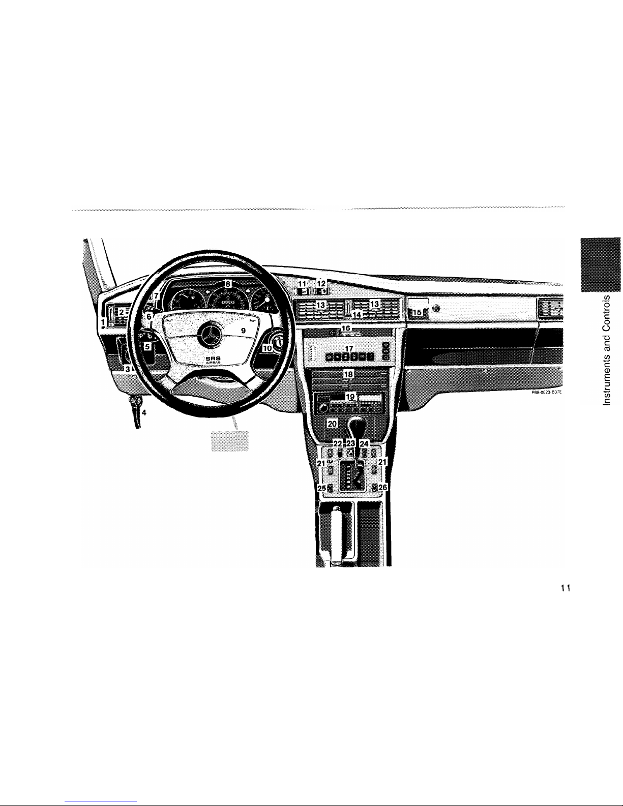
Instruments and Controls
For more detailed descriptions see Index.
14
15
1
2
3
4
5
6
7
8
9
10
11
12
13
Air volume control lever for side air outlets
Adjustable side air outlets
Exterior lamp switch
Hood lock release
Combination switch
Cruise control
Rear passenger compartment lamp switch
Instrument cluster
Horn, airbag
Steering lock with ignition/starter switch
Rear window defroster switch
Snow chain switch
Adjustable center air outlets
16
17
18
19
20
21
22
23
24
Loudspeaker front to rear fader control
25
Left front seat heater switch
26
Right front seat heater switch
Air volume control lever for center air outlets
Glove box, illuminated (only with key in steering
lock positions 1 or 2)
Fan speed control lever
Tempmatic climate control
Cassette box
Radio
Ashtray with lighter
Power window switch group
Hazard warning flasher switch
Adjusting switch for exterior mirror on front
passenger side
10
11
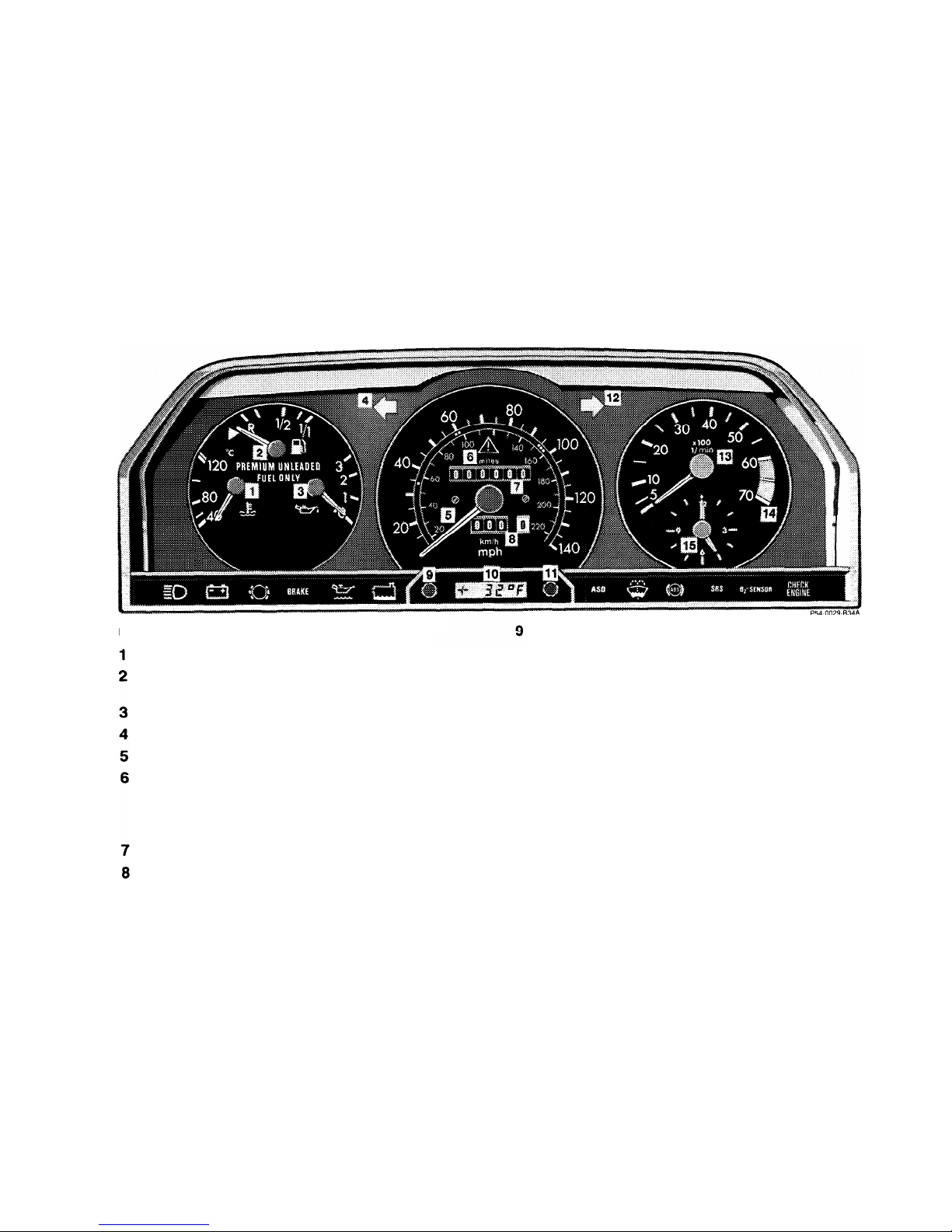
Instrument Cluster
Coolant temperature gauge. See Index
Fuel gauge with reserve warning lamp (yellow).
See Index
10
Engine oil pressure gauge (bar). See Index
Turn signal indicator lamp, left (green)
Speedometer
ASR function indicator lamp (yellow).
See Index
ASD function indicator lamp (yellow).
See Index
Main odometer
Trip odometer
11
12
13
14
15
Knob for instrument lamps and trip odometer
Rotate knob: to vary intensity of instrument
lamps
Depress knob: to reset trip odometer
Outside temperature indicator. See Index
Knob for clock adjustment
(press in and rotate for adjustments)
Turn signal indicator lamp, right (green)
Tachometer
Red marking on tachometer:
Excessive engine speed
Electric clock
12
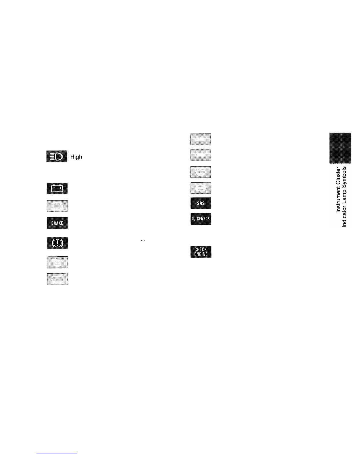
Indicator Lamp Symbols
Function Indicator Lamp
l-iigh
beam
Warning Lamps
(should go out with the engine running unless)
Battery not being charged.
See Index
Brake pads worn down.
See Index
Brake fluid low (except Canada).
Parking brake engaged.
See Index
Brake fluid low (Canada
only).
Parking brake engaged.
-.
See Index
Engine oil level low. See Index
Coolant level low. See Index
ASR malfunction. See Index
ASD malfunction. See Index
Fluid level for windshield and headlamp
washer system low.
See Index
ABS
malfunction. See
Index
SRS malfunction. See Index
190 E 2.3 (California version only)
Oxygen sensor replacement indicator
lamp: When the indicator lamp comes on,
the oxygen sensor must be checked and,
if necessary, replaced.
Engine malfunction indicator lamp
(California version only)
If the lamp comes on when the engine is
running, it indicates a malfunction in the
fuel injection system or emission control
system. In either case, we recommend
that you have the malfunction checked as
soon as possible.
See Index
13

Catalytic Converter
Your Mercedes-Benz is equipped
with monolithic catalytic converters, an important element in conjunction with the oxygen sensor to
achieve substantial control of the
pollutants in the exhaust
emissions. Keep your vehicle in
proper operating condition by
following our recommended
maintenance instructions as
outlined in your maintenance
booklet.
Caution!
To
prevent damage to the catalytic
converters, use only premium
unleaded gasoline in this vehicle.
Any noticeable irregularities in
engine operation should be repaired promptly. Otherwise
excessive unburned fuel may
reach the converter causing it to
overheat.
Warning!
As with any vehicle, do not
idle, park, or operate this vehicle in areas where combus-
tible materials such as grass,
hay or leaves can come into
contact with the hot exhaust
system, as these materials
could be ignited.
14

Starting and
Yurning
Off the
Engine
Before Starting
Engage parking brake and ensure
gearshift lever is in neutral (selector lever position “P” or “N” on
automatic transmissions). Turn key
in steering lock to position 2. The
charge indicator lamp should
come on.
Cold Engine
Do not depress accelerator. Turn
key in steering lock clockwise to
the stop. Release key only when
the engine is firing regularly.
Hot
Engine
Do not depress accelerator. Turn
key in steering lock clockwise to
the stop. If the engine has not
fired after approx. 4 seconds,
depress accelerator and continue
cranking until the engine is firing
regularly. Release key and back
off accelerator.
At very high coolant temperatures
the engine starting time can be
shortened if the accelerator is de-
pressed slowly at the beginning of
the starting process.
Turning off
Turn the key in the steering lock to
position 0 to stop the engine.
Note:
Vehicles with automatic trans-
mission: the key can only be removed with the selector lever in
position “P”.
If the coolant temperature is very
high (e. g. after hard driving on
mountain roads), do not shut off
the engine immediately, but allow
it to run for 1
-
2 minutes at in-
creased idle speed with selector
lever in neutral or position “P”.
Important!
Due to the installed starter
non-
repeat feature, the key must be
turned completely to the left before
attempting to start the engine
again.
Observe the oil pressure gauge
immediately after starting the
engine. In a very cold engine the
oil pressure will rise slowly after
the engine has started. Do not
speed up the engine before pressure is registered on the pressure
gauge. If you do not see the
gauge register oil pressure, stop
the engine and have it checked.
The charge indicator lamp should
go out as soon as the engine has
started.
In areas where temperatures
frequently drop below -13°F
(-25”C), we
recommend that an
engine block heater be installed.
Your authorized Mercedes-Benz
dealer will advise you on this
subject.
15
Driving Instructions
Power assistance
Warning!
When the engine is not
running, the brake and
steering systems are without
power assistance. Under these
circumstances, a much greater
effort is necessary to stop or
steer the vehicle.
Brakes
Caution!
When driving down long and steep
grades, relieve the load on the
brakes by shifting into a lower
gear (selector lever position “3”
or “2” in the case of automatic
transmission). This helps prevent
overheating of the brakes and
reduces brake pad wear. Do not
exceed engine speed limits (see
Index).
After hard braking it is advisable
to drive on for some time so the
air stream will cool down the
brakes faster.
Warning!
After driving in heavy rain for
some time without applying
the brakes or through water
deep enough to wet brake
components, the first braking
action may be somewhat reduced and increased pedal
pressure may be necessary.
Be sure to maintain a safe
distance from vehicles in
front.
The condition of the parking brake
system is checked each time the
car is in the shop for the required
maintenance.
Between maintenance checks, it is
a good practice to apply the parking brake once or twice while driving at aPproximately 30 mph
(50 km h) on a dry straight road.
Raise parking brake lever lightly
while holding the release button in
until a slight drag on the wheels is
felt. Keep applying brake for about
10 seconds while holding the
release button in before releasing
the parking brake completely. This
practice will keep the parking
brake at maximum efficiency.
Warning!
The stop lamps will not come
on when applying the parking
brake only. Perform the procedure in the previous paragraph only when the road is
clear of other traffic.
Resting your foot on the brake
pedal will cause excessive and
premature wear of the brake
pads.
It can also result in the brakes
overheating thereby significantly reducing their effective-
ness. It may not be possible to
stop the car in sufficient time
to avoid an accident.
All checks and maintenance work
on the brake system should be
carried out by an authorized
Mercedes-Benz dealer.
16
If the parking brake is released
and the brake warning lamp in the
instrument cluster stays on, the
brake fluid level in the reservoir is
too low.
Brake pad wear or a leak in the
system may be the reason for low
brake fluid in the reservoir.
Have the brake system inspected
at an authorized Mercedes-Benz
dealer immediately.
Install only brake pads and brake
fluid recommended by
Mercedes-
Benz.
Warning!
If other than recommended
brake pads are installed, the
braking properties of the vehicle can be affected to an
extent that safe braking is
substantially impaired.
. ... .
..... ... ... .
.................
..................................
......................
...........................................
.. ... .... .... ..
...
. .
.
‘.~.~.~.~.~.~.~.~.~.~.~.~.~.~.~.~.~.~.~.~.~.~.~.~.‘.~.~.‘.~.~.~.~.~.~.~.~.~.~.~.~.~.~.~.~.~.~.~.~.~.~.~.~.~.~.~.~.~
..........................................................
........................................................................................................
....................................................
.........................................................................................................
1801
...................................
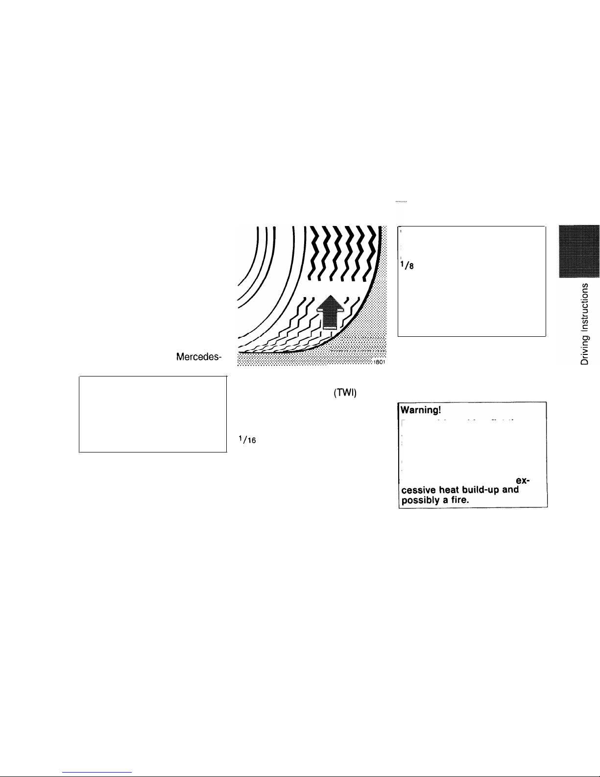
Tires
Tread wear indicators
(TWI)
are
required by law. These indicators
are located in six places on the
tread circumference and become
visible at a depth of approximately
l/16
in (2 mm), at which point the
tire is considered worn and should
be replaced.
The tread wear indicator appears
as a solid band across the tread.
Warning!
Do not allow your tires to wear
down too far. With less than
'/8
in (3 mm) of tread, the
adhesion properties on a wet
road fall off sharply.
Depending upon the weather
and/or road surface (conditions), the traction varies
widely.
Specified tire pressure must be
maintained. This applies particularly if the tires are subjected to
high loads (e. g. high speeds,
heavy loads, high ambient
temperatures).
Do
not drive withaflat tire.
A flat tire affects the ability to
steer or brake the vehicle. You
may lose control of the car.
Continued driving with a flat
tire or driving at high speed
with
a flat tire will cause
ex-
17
Aquaplaning
Depending on the depth of the
water layer on the road, aquaplaning may occur, even at low
speeds and with new tires. Avoid
track grooves in the road and
apply brakes cautiously in the rain.
Tire traction
The safe speed on a wet, snow
covered or icy road is always
lower than on a dry road.
You’ should pay particular attention
to the condition of the road as
soon as the prevailing temperatures fall close to the freezing
point.
trally
reduced.
Under such
weather conditions, drive,
steer and brake with
extreme
We recommend M + S radial-ply
tires for the winter season for all
four wheels to insure normal
balanced handling characteristics.
On packed snow, they can reduce
your stopping distance as compared with summer tires. Stopping
distance, however, is still considerably greater than when the road
is wet or dry.
Parking
Warning!
To reduce the risk of personal
injury as a result of vehicle
movement, before turning off
the engine and leaving the
vehicle always:
1. Keep foot on brake pedal.
2. Pull up parking brake lever.
3. Engage first or reverse gear
(selector lever position “P”
in the case of automatic
transmissions).
4. Slowly release brake pedal.
5. Turn front wheels towards
the road curb.
6. Turn the key to steering
lock position 0 and remove.
Important!
It is advisable to set the parking
brake whenever parking or leaving
the vehicle. In addition, engage
first or reverse gear (selector lever
position “P”).
When parking on hills, always
apply the parking brake.
Clutch
Caution!
Resting your foot on the clutch
pedal will cause excessive and
premature wear of the clutch disc.
18

Winter Driving Instructions
The most important rule for
slippery or icy roads is to drive
sensibly and to avoid abrupt ac-
celeration, braking and steering
action. Do not use the cruise
control system under such
conditions.
When the vehicle is in danger of
skidding, declutch, or in case of
an automatic transmission move
selector lever to position “N”. Try
to keep the vehicle under control
by corrective steering action.
..,,.
Road salts and chemicals can ad-
versely affect braking efficiency.
Increased pedal force may be-
come necessary to produce the
normal brake effect. We therefore
recommend depressing the brake
pedal periodically when traveling
at length on salt-strewn roads.
This can bring road salt impaired
braking efficiency back to normal.
A prerequisite is, however, that
this is done without endangering
other drivers on the road.
If the vehicle is parked after being
driven on salt treated roads, the
braking efficiency should be tested
as soon as possible after driving is
resumed while observing the safe-
ty rules in the previous paragraph.
Warning!
If the vehicle becomes stuck
in snow, make sure that snow
is kept clear of the exhaust
pipe and from around the ve-
,
hicle
with engine running.
Otherwise, deadly carbon
monoxide (CO) gases may
enter vehicle interior resulting
in unconsciousness and
death.
To assure sufficient fresh air
ventilation, open a window
slightly on the side of the car
that is out of the wind.
19
. . . . . . . . . . . . . . . . . . .
/
,.1_....,,.......,,.
%,.,” . . . . . . . . l...l . . . . . . . .
.,\....
.,
. . . . . . . . . . .
I
Tempmatic Climate Control
Car Keys
Opening the Doors
Lock;oysand
Unlocking of
Central Locking System
Anti-Theft Alarm System
Manual Seat Adjustment,
Front
Power Seats, Front
Orthopedic Seat Backrest
Armrest (Front Seats)
Armrest (Rear Bench Seat)
Head Restraints, Rear
Heated Seats
;8’
29
Operation
Seat Belts and Supplemental
Restraint System (SRS)
38
Steering Lock
Exterior Lamp Switch
2:
Combination Switch
51
Shelf below Rear Window
52
Inside Rear View Mirror
Exterior Rear View Mirrors
z:
Sun Visors
54
Interior Lamps
Rear Window Defroster
zz
Lighter
56
Sliding Roof with Rear
Pop-Up Feature
Power
Wrndows
55;
Antenna
58
Cellular Telephone
58
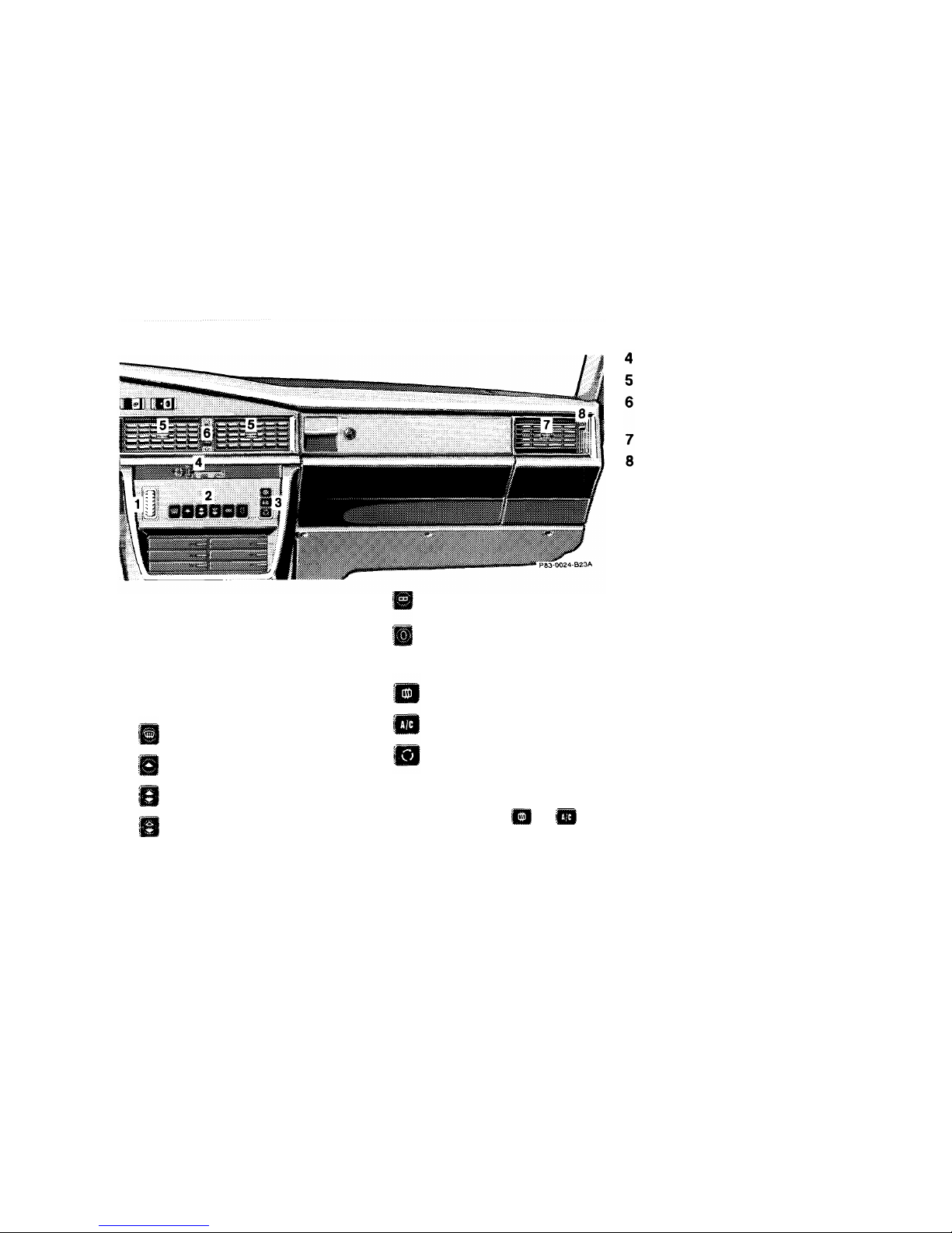
Tempmatic Climate Control
=
Normal cooling or fresh
The engine must be running for
air ventilation
the climate control system to
= Off (air supply off)
operate.
1
Temperature selector
3 Air conditioning mode control
2 Pushbuttons for function select-
ion (only press individually)
= Dehumidifying
= Defrost
= Normal setting
= Defog
= Recirculated air switch
(red indicator lamp in
= Heating and cooling
the button comes on. The but-
ton returns to initial position).
= Normal heating
If either button im or !m are
depressed, the air conditioning
compressor is switched on.
Fan speed control lever
Adjustable air outlets
Volume control lever for
adjustable air outlets (5)
Adjustable air outlets
Volume control lever for
adjustable air outlets (7)
The button symbols light up when
the vehicle’s exterior lamps are
turned on. The symbol is brighter
when depressed.
Close all windows and the sliding
roof to ensure proper operation of
the system. Air outlet temperature
is controlled automatically.
Note:
The air conditioner removes considerable moisture from the air
during operation. It is normal for
water to drip on the ground from
the underbody.
22
. . . . . . . . . . . . . . . . . . . . . . ,,,,,,,,,,,,,,,,,,,..,,,,,,.......
Air Distribution
Air conditioned, warmed, or fresh air may be
directed to the foot area, the windshield, and the
side outlets (7). The center outlets (5) are for
non-
heated air only.
The air volume through the center outlets (5) and
side outlets (7) can be varied with levers (6) and (8)
respectively. Pushing the lever up opens the air
outlets completely.
Temperature Selection
FR
Use the temperature selector to set the desired
1
i
temperature. The selected temperature is
I!J
reached as quickly as possible and maintained.
Use a basic setting of “72”. Refine your setting
only in small steps to avoid large temperature
fluctuations.
Turning downwards (notched-in) = maximum cooling
or fresh air dependent on push button selection of
the air conditioning mode control.
Turning upwards (notched-in) = maximum heating.
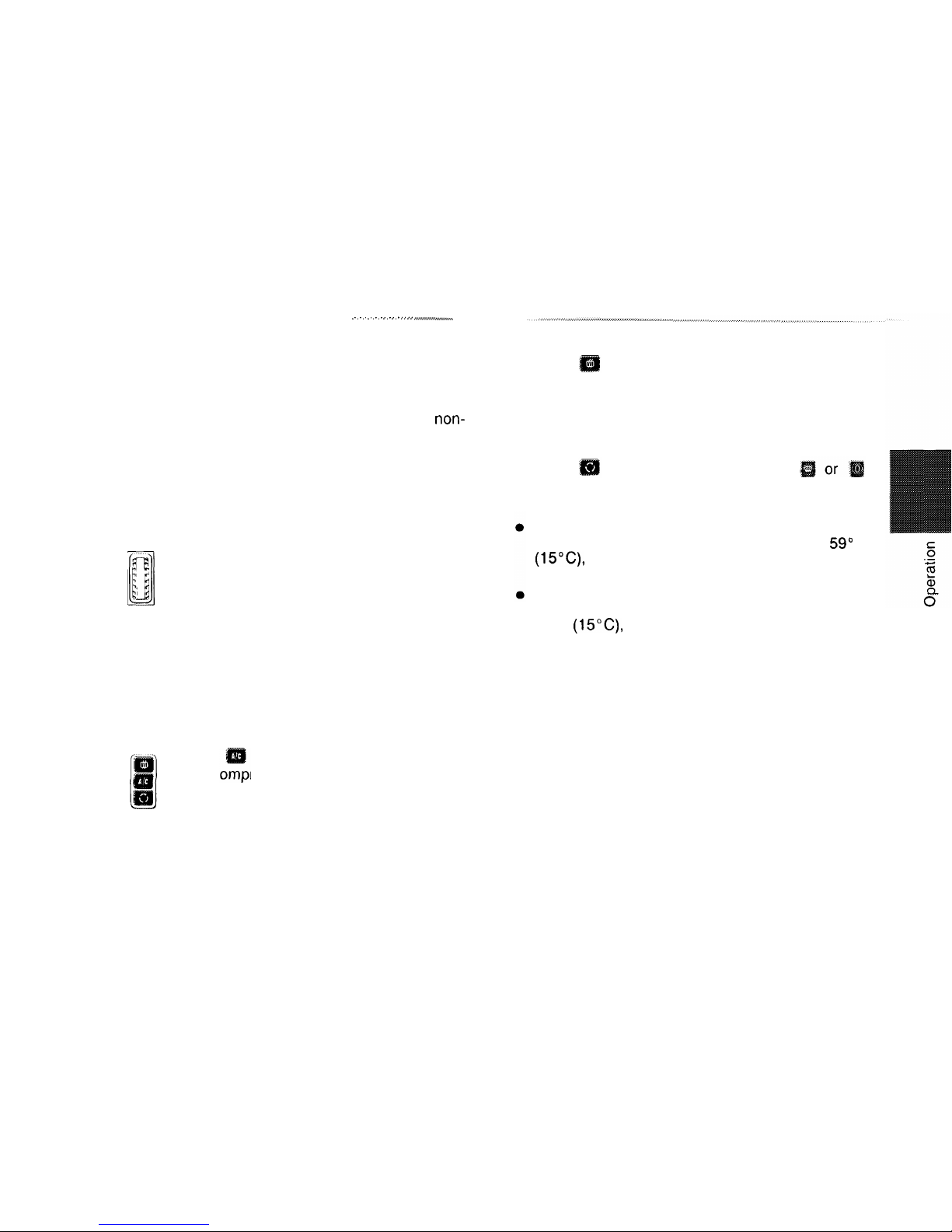
A/C Mode Control Switch
Position = Normal cooling, the air conditioning c
ressor is switched on.
The vehicle may be heated or cooled as de-
sired. The compressor comes on if the vehicle’s
interior temperature exceeds the selected temperature. The selected temperature is then maintained
by regulating the compressor’s running time.
Position
= Dehumidifying, the air conditioning
compressor is switched on.
The climate control system works at maximum
capacity, removing moisture from the air. This mode
is recommended during humid weather and when
windows must be defogged from inside.
Position
= Recirculated air (buttons
must not be depressed).
Recirculated air switch pressed:
Cooling Mode
If the outside temperature exceeds approx. 59” F
(15”C), the system will automatically change
from recirculated air to fresh air after 30 minutes.
Heating Mode
If the outside temperature is less than approx.
59°F
(15°C)
the system will automatically
change from recirculated air to fresh air after
5 minutes.
This setting can also be used if annoying odors or
dust are entering the car’s interior.
At high outside temperatures the air conditioning
system is automatically in the recirculated air mode,
providing increased cooling.
23
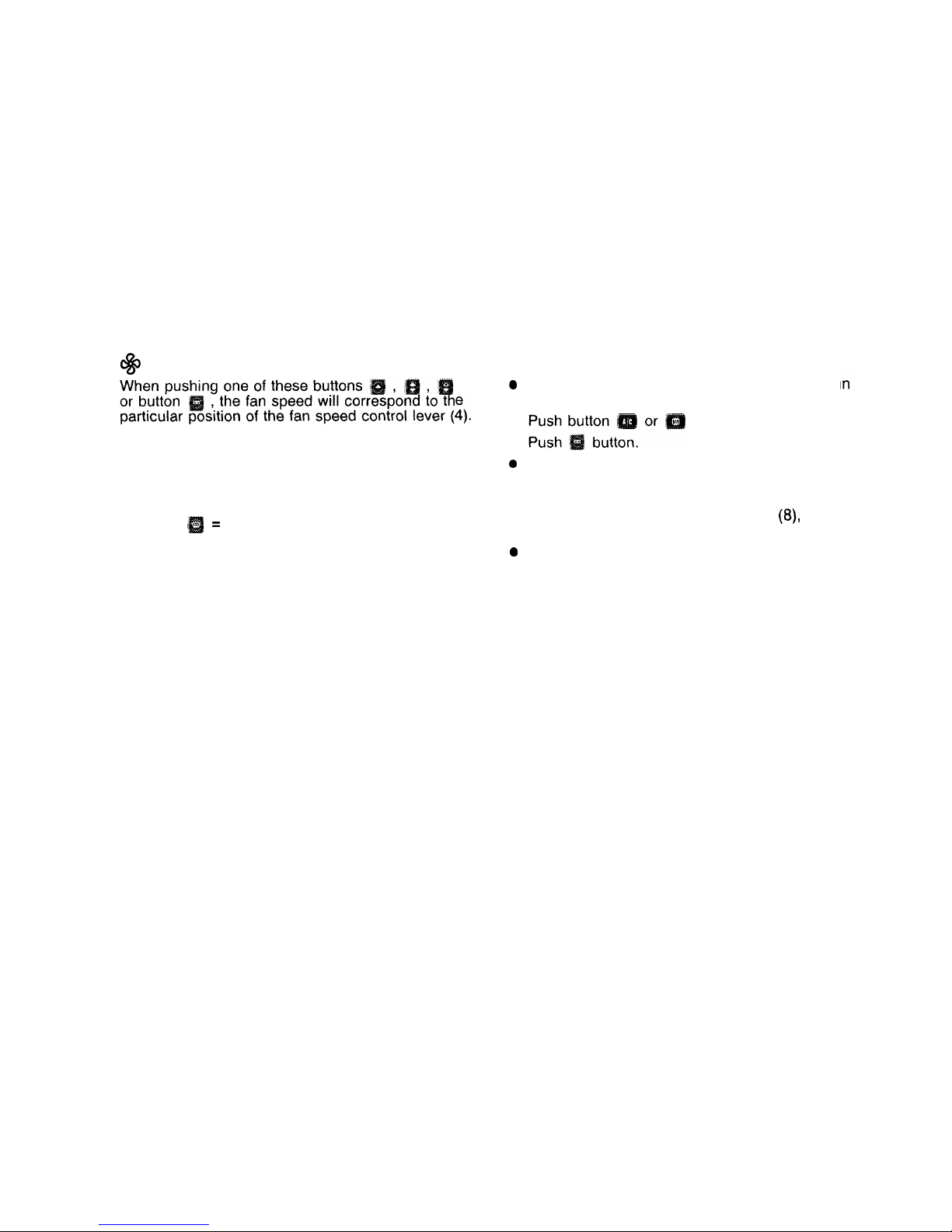
@
Fan Speed Selection
Fast Cooling
0
t.
l
The volume of fresh air supplied to the vehicle
interior can be increased by pushing lever (4) to the
l
right.
0
The fan speed may be changed by moving lever (4)
to position “II”, “II!” or “max”.
.
Function
I
=
Maximum fan speed engaged.
0
Turn temperature selector wheel (1) and lock
the lower end position.
in mode control (3).
Move fan speed control lever (4) to far right
“max” position.
Open adjustable air outlets (5) and (7) completely by pushing up levers (6) and
(8)
respectively.
Close windows and sliding roof completely.
Note:
Open the windows and/or sliding roof long enough
to let hot air inside the car escape. This helps reduce the time the air conditioner must run before
the car cools. Then, close windows and/or sliding
roof and allow air conditioner to operate to its full
capacity.
24
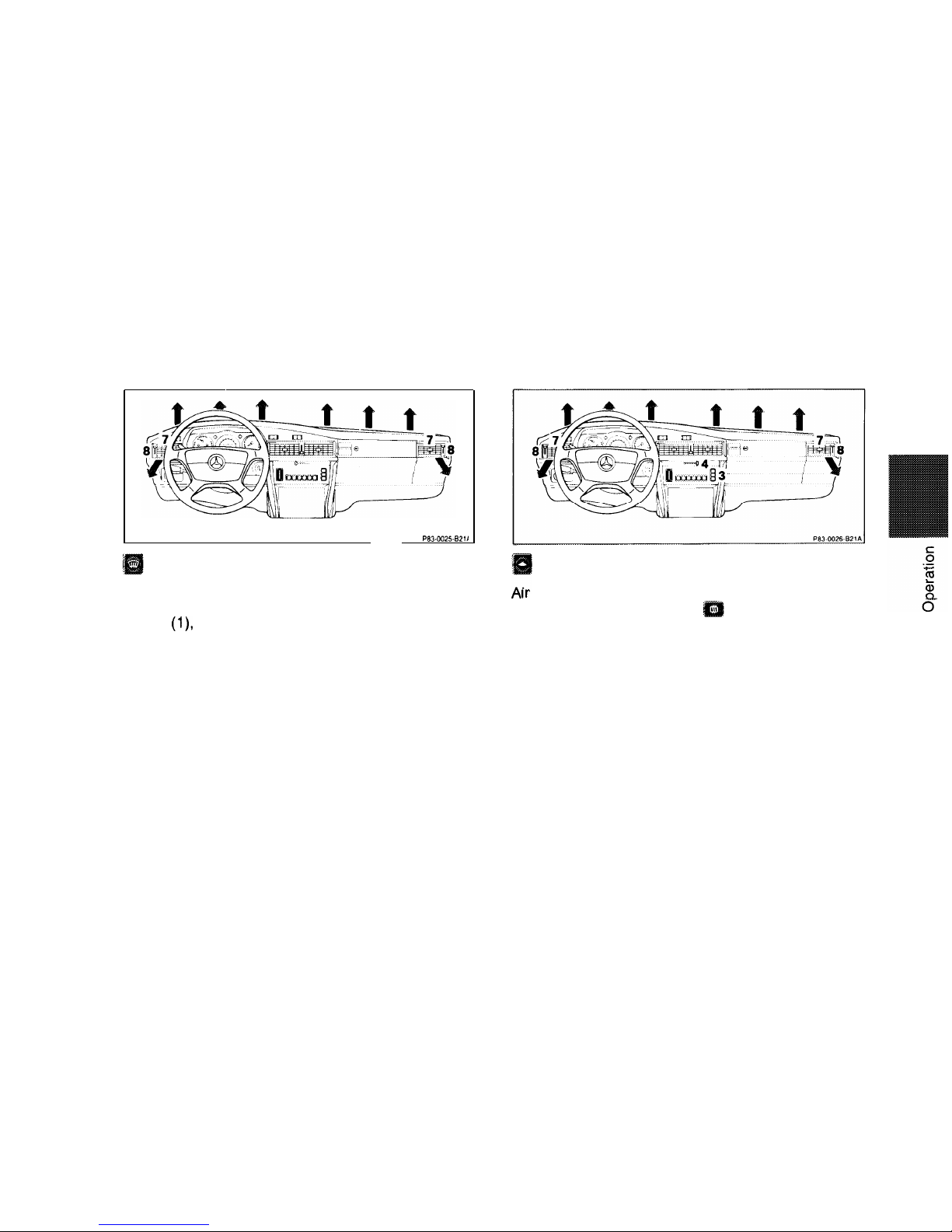
Examples of Air Flow Adjustments
Pm-0025-6211
Press to defrost or quickly defog windows.
Maximum heated air is directed to the windshield
and side windows, independent of the temperature
setting
(1)
mode control (3) and fan speed control
lever (4) position. The air volume through outlets (7)
may be adjusted with levers (8) as desired.
Press to defog the inside of the windshield.
rr
is directed to the windshield in the heating or
cooling mode. Press button
of mode control (3)
and increase fan speed for a short period with
lever (4). Adjust levers (8) for the desired air flow
through outlets (7).
It is possible for condensation to form on the outside of the windshield in humid weather in this
mode. If this happens, change the air flow or decrease the fan speed.
25
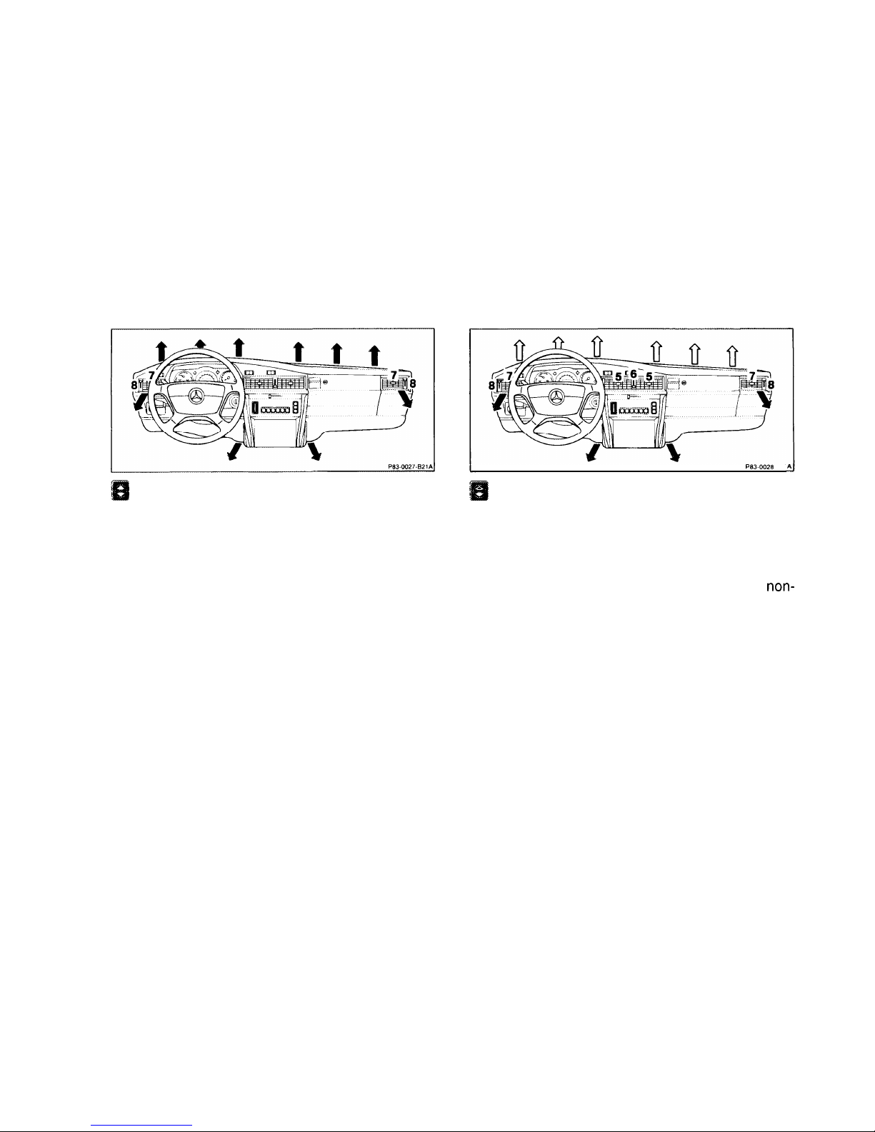
Press for heating.
In this type of operation, air is directed to the windshield and the foot area. The air outlets (7) may be
opened or closed with levers (8) as desired.
If the ambient temperature is above 32°F (0°C) the
air conditioning compressor may switch on automatically to dry the heated air.
Ptw0028
821
Press for normal heater operation.
Most of the air is directed to the foot area during
heater operation. A small amount of air is directed
to the windshield, just enough to keep it from fogging up during normal weather conditions. The air
outlets (5) and (7) may be opened or closed with
levers (6) and (8) respectively as desired. Only
non-
heated air is directed through outlets (5).
26
., ., ., . . . . . . .
I
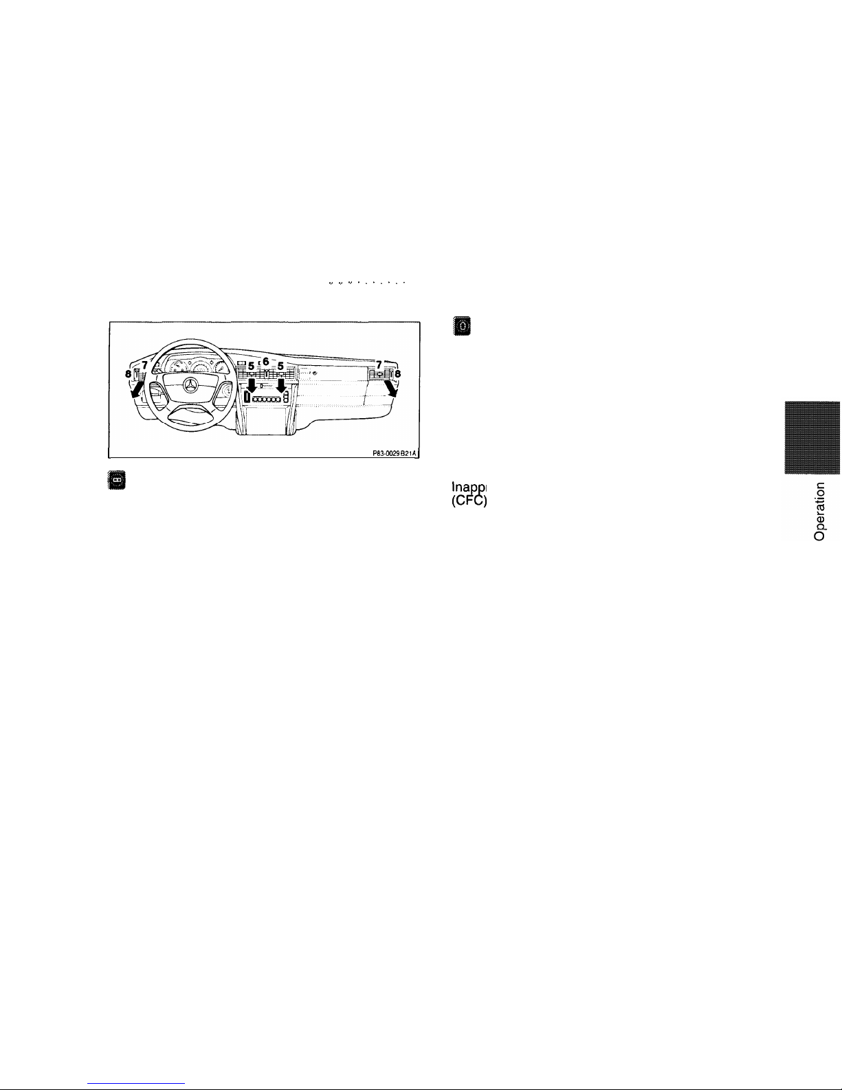
pm-0029 I321 P
Press for fresh air ventilation or air
conditioning.
For taking in fresh air or during air conditioner
operation, the air is directed to outlets (5) and (7).
Adjust the air flow with levers (6) and (8) respectively as desired.
Off.
In this setting, the Tempmatic Climate Control is
shut off, including the fresh air supply to the interior
of the car (to prevent entrance of odors, i. e. while
driving through tunnels etc. or to prevent the entrance of water from automatic car wash). Use this
setting only temporarily while driving with windows
and sliding roof closed since the vehicle’s normal
interior airflow will be disrupted.
Important!
Ina
ropriate repair work may cause refrigerant
(CPE;
to escape into the atmosphere and contribute
to the depletion of the earth’s ozone layer.
Repairs should always be performed by a qualified
technician, and refrigerant should be collected in a
recovery system for recycling.
27
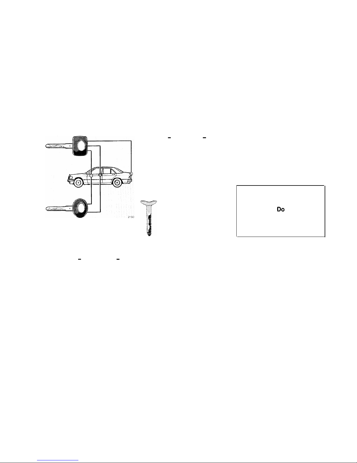
Car Keys
Included with your vehicle are two
master keys, one valet key and
one flat (master) key.
Master Key - square head - fits
all locks on the car. Arms/disarms
the anti-theft alarm system.
Note:
Do not give the master key to an
unauthorized oerson.
Valet Key - round head - works
only in the door locks and the
steering lock. Arms/disarms the
anti-theft alarm system. The valet
key will not fit the trunk or glove
box locks. This key should be
used whenever the car is left with
an attendant. Be sure to lock glove
box and trunk with the master key.
Flat Key
The flat key fits all
vehicle locks. Arms/
disarms the anti-theft
alarm system. We
recommend that you
carry the flat key with
you and keep it in a
safe place so that it is
always handy. Never
leave the flat key in the
vehicle.
Obtaining Replacement Keys
Your vehicle is equipped with a
theft deterrent locking system requiring a special key manufactur-
ing process. For security reasons,
replacement keys can only be
obtained from your authorized
Mercedes-Benz dealer.
Warning!
When leaving the vehicle al-
ways remove the key from the
steering lock. Do not leave
children unattended in the
vehicle. Unsupervised use of
vehicle equipment may cause
serious personal injury.
28
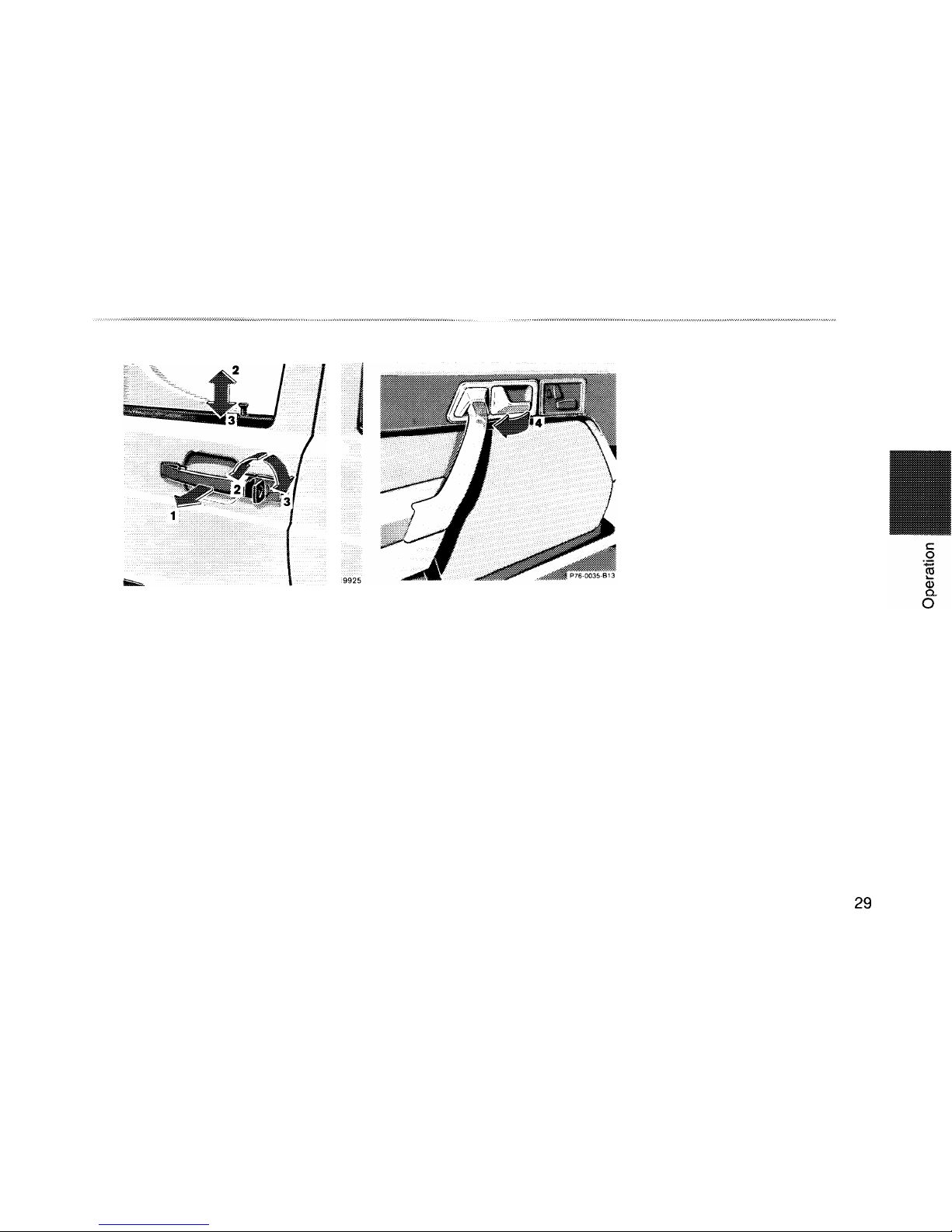
Opening the Doors
From outside: pull handle (1)
outwards.
From inside: pull handle (4) in
door trim panel.
Locking and Unlocking of Doors
From the outside: turn key.
From the inside: actuate door lock
button.
2 Unlocking
3 Locking
When the rear door lock buttons
are down, the rear doors cannot
be opened from the outside or the
inside, unless the door lock buttons are first pulled up.
One cannot lock:
l
the driver’s door if it is open
l
any door if the door latch has
not engaged fully. In this case
open the door and close it
again.
29

Central Locking System
The entire vehicle may be locked
or unlocked with the central lock-
ing system by:
l
Using the master
either front door.
or valet key in
l
Using the master key in the
trunk lock.
l
Pushing down or pulling up the
interior door lock button at
either front door.
The central locking system locks
or unlocks all doors, trunk lid and
fuel filler flap simultaneously.
Doors
When you lock the car, all door
lock buttons should move down. If
any one stays up, the respective
door is not properly closed. You
should then unlock the car, open
and
reclose
this door, and lock the
car again.
The central locking system can be
enaaged from the driver’s door
lot
button, provided the door is
completely closed. It can also be
engaged from the front passenger
door if the ignition key is removed,
or the key is inserted in the
steering lock without having been
turned (key in position 0).
If the car has been locked from
the outside, the anti-theft alarm (if
so equipped) will come on if a
door is opened from the inside.
Trunk
To unlock the trunk with the
central locking system, turn the
master key in the trunk lock completely to the left and return it to
the vertical position. Push in trunk
lock button and open the trunk. To
lock the trunk, turn the master key
completely to the right and return
it to the vertical position.
The trunk can remain locked while
the central locking system is un-
locked (e. g. while driving or when
leaving the car in a situation
where it must be driven using the
valet key but you wish the trunk to
remain locked at parking lots,
workshops etc.). Turn the master
key completely to the right and
pull it out in the horizontal position. Now the trunk can only be
unlocked with the master key by
turning it back completely to the
left.
Important!
If the trunk is unlocked with the
master key, the doors and fuel
filler flap will also be unlocked.
After closing the trunk, the central
locking system must again be
engaged using the key to
relock
the doors and fuel filler flap.
Note:
If the fuel filler flap cannot be
opened, refer to Manual Release
of Fuel
Filler
Flap (see Index).
30
Anti-Theft Alarm System
The anti-theft alarm is automatically armed or disarmed with the
master key, valet key or flat key by
locking or unlocking either front
door or the trunk.
Operation
Once the alarm system has been
armed, the exterior vehicle lamps
will flash and the horn will sound
intermittently when someone:
opens a door,
opens the trunk,
opens the hood,
removes the radio,
switches on or bridges the
ignition circuit,
steps on the brake pedal.
The alarm will last
aooroximatelv
Note:
150 seconds in the form of
blink-
ing exterior lamps. At the same
We recommend that you carry the
time an additional horn will sound
flat key safely with you so that it is
intermittently for 60 seconds,
always handy. This key has the
pause for 30 seconds, and repeat
same function as the master key.
for another 60 seconds.
The alarm will stay on even if the
activating element (a door, for example) is immediately closed.
31
 Loading...