

Page 1

r
Transporters • Electrical System
VITO/VIANO (Model 639)
Wiring Diagrams
a
mb
Technical training for Customers
As at 06/05
Page 2

Wiring Diagram Manuals Part Number: Z6517 2111 02
This document is intended solely for use in training and is not subject to regular updating. Part numbers and
documentation included in this document may change and the latest information should always be used.
Printed in England
Æ 2005 Copyright DaimlerChrysler UK LTD
Publisher: Mercedes-Benz CV Electrics & Telematics Team
This document with all its sections is protected under the laws of copyright. Its use for any purpose whatsoever
requires the prior written consent of DaimlerChrysler UK LTD. This applies in particular to its reproduction,
distribution, modification, translation, recording on microfilm or storage and/or processing in electronic systems,
including databases and on-line services.
Note:
The term »employees« does not imply any
preference of gender and incorporated male and
refers to male and female employees alike.
Page 3

Contents
Chapter Title
1 Use of wiring diagrams
2 Abbreviations for wiring diagrams
3 Location and assignment of ground points
4 Location and assignment of plug connectors
5 Battery starting charging circuit
6 Voltage supply fuses
7 Fuse and relay board (SRB)
8 Signal Acquisition and actuation module (SAM)
9 Exterior lights
10 Central locking
11 CAN bus
12 Instrument cluster (IC)
13 Electronic ignition switch (EIS)
14 Electronic stability control (ESP)
15 Common rail diesel injection (CDI)
16 Standard heater
06/05 Transporters • Electrics <>Van - Electrical Systems
Wiring Diagrams VITO (Model 639)
Page 4

Use of Wiring Diagrams Chapter 1
06/05 Transporters • Electrics <>Van - Electrical Systems
Wiring Diagrams VITO (Model 639)
Page 5

OV00.01-S-1901-03VA Use of wiring diagrams
Wiring diagrams
The wiring diagrams are assigned to the familiar function groupsa
00-91. The systems are listed alphabetically with an indication of
the function group/ function subgroup in the "Search aid for all
wiring diagram groups"
OV00.01-S-1901VA or A3 (paper version).
The wiring diagrams are filed in the respective function groupa
arranged according to the PE number,
e.g.: PE07.16-S-2000VA
PE07.16-S-2000IVB
To check the completeness of the volume the sequence of the
wiring diagrams filed can be seen from the lists of contents of the
respective function group. For supplements the wiring diagrams
should be filed as per the supplement sheet.
e.g.: PE00.19-P-1100VA Overview of wiring diagrams....
-----------------------------------------------------------------------------------
Noteson the accompanying documents for connectors/ terminala
blocks (B1)
Special equipment (SA) is specifically highlighted in the notes
column. For connectors, which are installed in special
equipment, the special equipment is specified in the notes
column in the row in front of the connector designation. For
connectors, which are installed as standard, special
equipment specification is noted directly at the respective jack
and/or connector.
The wiring diagramsare prepared as function diagrams or controla
unit diagrams and are built up as follows:
-Function diagrams
The control units and electrical components belonging to the
function are shown as symbols. The functional connections are
realized by direct lines or by the data bus.
-Control unit diagrams
Control units are represented complete with all connected
components. The feed of the control units appears first.
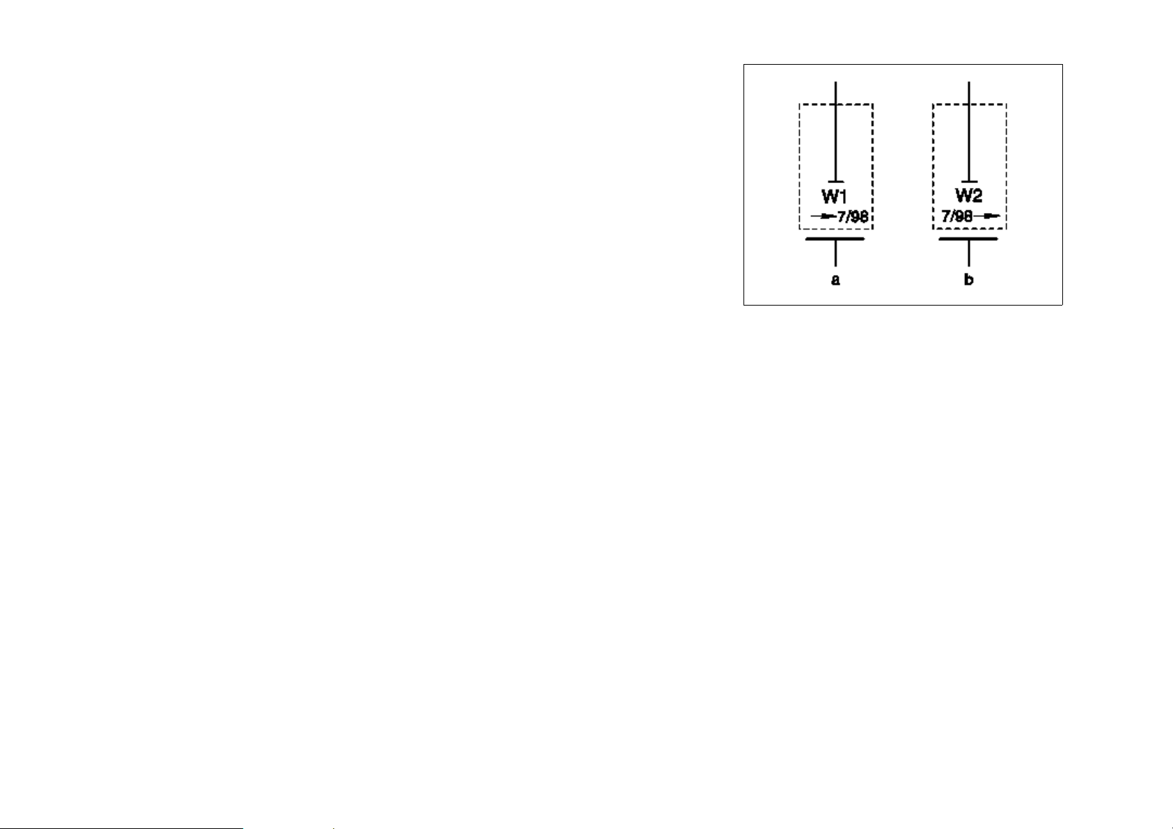
The wiring diagrams also contain linkages of possible versions and
functions.
Linkages, recognizable as versions, are framed and provided with
an abbreviated designation/ abbreviation.
The versions are designated with 1
and 2
-------------------------------------------------------------------------------------
The feed of the terminal blocks is shown by means of an
arrow pointing to the left, the outputs by means of arrows
pointing to the right. The grouping of the individual variants/
special equipment (SA) is highlighted by means of broken
lines. All outputs to components, which are installed as
standard, are listed up to the first broken line.
Page 6
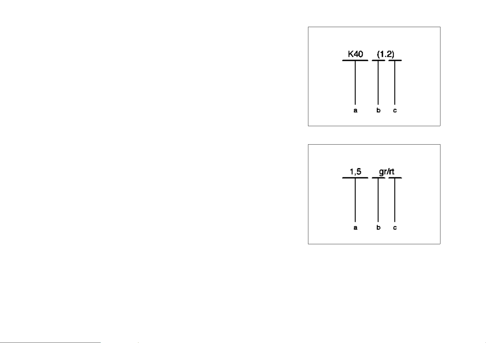
Connection designation
a Component
b Clutch
c Socket
Wire designation
a Conductor cross-section in mm
b Basic color
c Identification color
P00.19-0402-01
2
P00.19-0403-01
Page 7
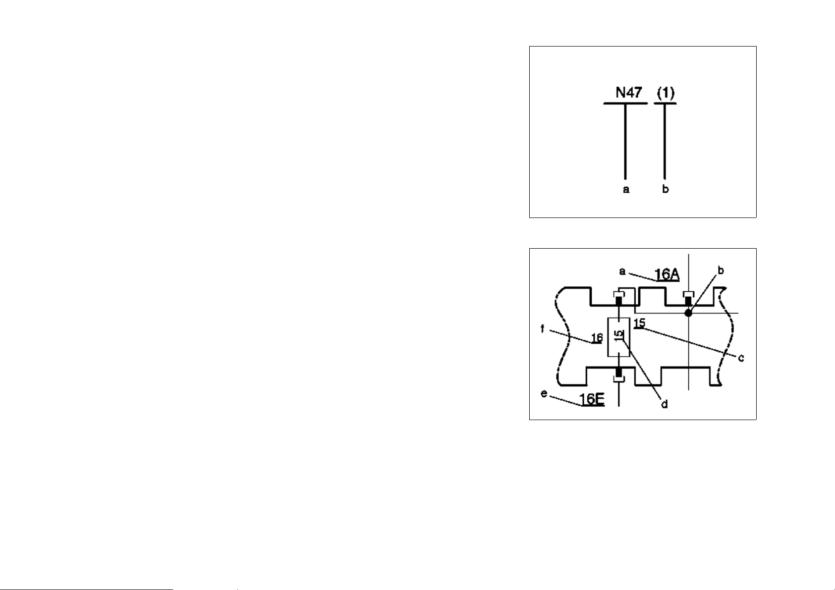
Identification of truncated wires
a Component to which the truncated electric line leads
b Connection designation on component
Fuse blocks
a Receptacle numbering, output (A, B, C or D)
b Line bridge
c Terminal designation
d Fuse rating in amp(s)
e Receptacle numbering, input (E)
f Fuse number
Page 8
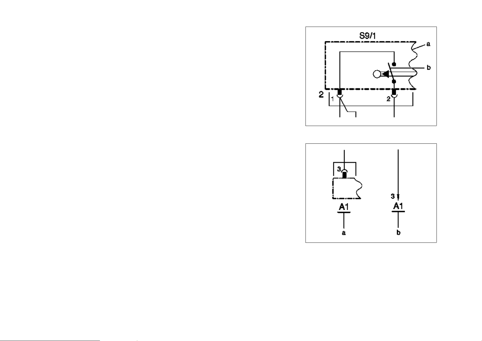
Components and switches
a Component which are not represented completely are shown dismantled.
b Switching contacts are shown in the rest position.
a Illustration of a function-specific component with connection designation and
corresponding line
b Illustration of a function-independent component connection with corresponding line
Page 9
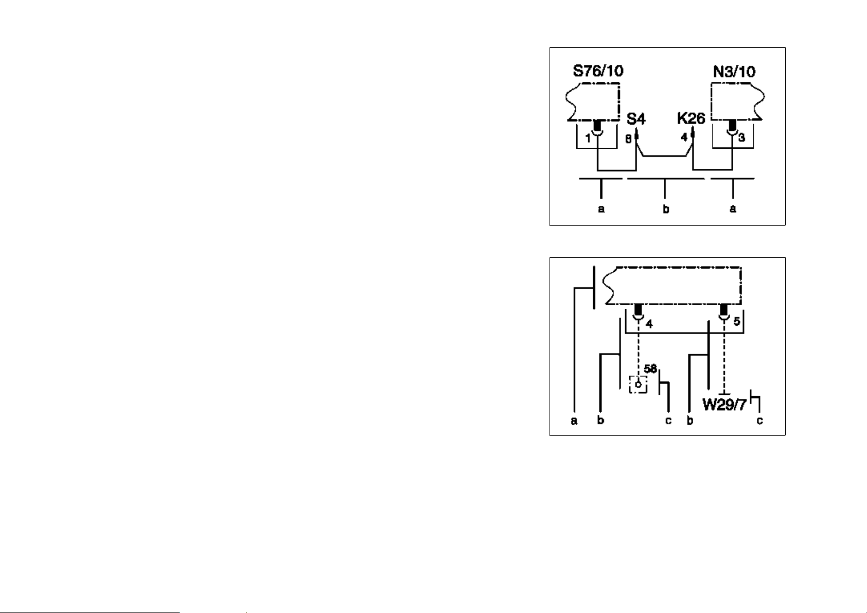
Looped lines
a Function-specific components
b The looped line connects two function-specific components across one or more function-
independent component connections.
Indirect line (only for terminal 31 or terminal 58)
a Function-specific component
b Indirect line for more than two intermediate function-independent component connections/
loops.
c Connection to either terminal 31 or terminal 58
P00.19-2089-01
Page 10
Installation date
a Installation of a component up to date
b Installation of a component as of date
BK = Black = black
BN = Brown = brown
BU = blue = blue
GN = green = green
GY = gray = gray
OG = orange = orange
PK = pink = pink
RD = red = red
TR = transparent = transparent
VT = violet = violet
WH = white = white
YE = yellow = yellow
P00.19-2094-01
Page 11

Abbreviations for Wiring Diagrams Chapter 2
06/05 Transporters • Electrics <>Van - Electrical Systems
Wiring Diagrams VITO (Model 639)
Page 12

OV00.01-S-1001-27VA Abbreviations for wiring diagrams MODEL 639.601/603/605/701/703/
705/711/713/811/813/815
Abbreviation Designation Code FG.FUG
AB Airbag 91.00
ABL Exterior lights 82.10
ABS Antilock brake system 42.30
AT Automatic transmission G40 - Automatic transmission 27.19
AHV Trailer hitch Q22 - Fixed trailer hitch
31.19
Q50 - Trailer hitch with detachable ball head
AKC Anti-knock control
ACSR Automatic child seat recognition 91.60
BCAPC Barometric pressure/charge air pressure
compensation
APS Auto pilot system EN2 - Auto pilot system with TMC interface
82.61
EN4 - Auto pilot system with TMC interface,
large display
EN9 - Auto pilot system for Japan, large display
EGR Exhaust gas recirculation 14.20
ART Adaptive cruise control IN18 - Distronic
DSV Drive authorization system shutoff valve (DSV) 80.35
ASR Acceleration slip regulation BB3 - Electronic Stability Program (ESP) 42.40
ATS Antenna systems 82.62
82.70
BAS Brake Assist BB3 - Electronic Stability Program (ESP) 42
CDI Common rail diesel injection 07.16
CDC CD changer EP5 - CD changer 82.64
D2B Digital data bus EH3 - Portable CTEL preinstallation linked to
82
D2B network
Copyright Daimler Chrysler AG 03.12.2005 CD-Aus gabe G/11/05 . This WIS print-out will not be recorded by M odification services . Page 1
Page 13

OCP Overhead control panel control unit LD0 - Dome lamp with reading lamp for
54.21
driver/front passenger
DTR Distronic (adaptive cruise control) IN18 - Distronic
EDC Electronic diesel control 07.16
EDS Electronic diesel system 07
ATA Anti-theft alarm system FZ5 - Anti-theft alarm system 80.50
EFH Power windows 72.29
ISC Electronic idle speed control 07
ELC Electronic level control CL0 - Rear lowerable/raisable air suspension 32.33
ESP Electronic stability program BB3 - Electronic Stability Program (ESP) 42.45
ESA Electric seat adjustment SF1 - Electrically adjustable luxury driver seat 91.00
DFI Diesel injection system (electronic distributor-
07.16
type fuel injection)
EIS Electronic ignition switch control unit 54.21
RFL/IRCL Radio frequency locking/infrared remote central
FZ5 - Anti-theft alarm system 80.50
locking
HFS Hands-free system 82.70
GPS Global positioning system
ETR Emergency tensioning retractor 91.00
HEAT Automatic heater 83
HFM-SFI HFM sequential multiport fuel injection/ignition
07.61
system
HHS Heated rear window 67.29
IRCL Infrared remote central locking 80.20
IMS Interior motion sensor 80.50
TWC Catalytic converter 07
IC Instrument cluster 54.30
AAC Automatic air conditioning HH4- Automatic air conditioning 83.00
LHD Left-hand drive vehicle
ISC Idle speed control
LS Power steering gear
Copyright Daimler Chrysler AG 03.12.2005 CD-Aus gabe G/11/05 . This WIS print-out will not be recorded by M odification services . Page 2
Page 14

HRA
Headlamp range adjustment
82.10
ME-SFI
MT
MOST
REST
OSL
PTS
RHD
SR
HS
SOUND
SPH
HCS
STH
TEL
ME-SFI fuel injection and ignition system
Manual transmission
Media Oriented System Transport
Residual engine heat utilization system
Orthopedic seat backrest
Parktronic system
Right-hand drive vehicle
Tilting/sliding roof
Heated seats
SOUND systems
Mirror heater
Headlamp cleaning system
Stationary heater
Telephone
EZ8 - Parktronic System (PTS)
D24 - Glass tilting/sliding roof in passenger
compartment
D27 - Glass tilting/sliding roof in driver
compartment
H15 - Heater for front passenger
H16 - Heater for driver seat
H12 - Warm water auxiliary heater
H85 - Preinstallation for auxiliary heater
HZ1 - Warm air auxiliary heater (Westfalia)
EH3 - Portable CTEL preinstallation linked to
D2B network
JV4 - Portable CTEL telephone preinstallation
07.61
82
54.65
54.21
77.20
91.00
82.85
88.79
82.35
83.70
82.70
TELE AID
Telematic Alarm Identification on Demand
(emergency call system)
DCU
HB
CL
Copyright Daimler Chrysler AG 03.12.2005 CD-Aus gabe G/11/05 . This WIS print-out will not be recorded by M odification services . Page 3
Door control unit
Heater booster
Central locking
EZ9 - Car telephone emergency call system
(Tele Aid)
HZ9 - Heater booster
72.29
83.70
80.20
Page 15

OV00.01-S-1001-28VA Abbreviations of signal and circuit designations
for wiring diagrams
Abbreviation Designation Notes
(+) Positive
(-) Negative
15 Switched positive
30 Battery voltage, positive (continuous positive)
31 Return line to battery negative or ground, direct
49 Turn signal generator input
49a Turn signal generator output
49L Left turn signal lamp
49R Right turn signal lamp
50 Starter control (direct)
55 Front fog lamp
56 Headlamp light
56a High beam and high beam indicator
56b Low beam
58 Position, tail, license plate and instrument lamps
58d Variable instrument/switch illumination
61 Alternator monitor
85 Negative or ground winding end
86 Start of winding
87 Input
87a First output (NC side)
87b Second output
87c Third output
A-CDW-SIG CD-player with changer signal
Copyright Daimler Chrysler AG 03.12.2005 CD-Aus gabe G/11/05 . This WIS print-out will not be recorded by M odification services . Page 1
Page 16

A-P-EV1 Output - pulse width signal - injection valve, cyl. 1
A-P-EV2 Output - pulse width signal - injection valve, cyl. 2
A-P-EV3 Output - pulse width signal - injection valve, cyl. 3
A-P-EV4 Output - pulse width signal - injection valve, cyl. 4
A-S-LSHVK Output - shift signal - oxygen sensor heater
A-S-RPR Output - fuel pumps signal - relay
A-STAR Output - starting relay
A-T-LUES Output, fan control
A-ZUE1 Output, ignition coil 1
A-ZUE2 Output, ignition coil 2
AE Trailer recognition
AKSE (CSD) Automatic child seat recognition (ACSR)
AL Exit lamp
AS Towing sensor
ASS/IRS Towing sensor/interior protection
ASV 1 Intake solenoid valve 1
ASV 2 Intake solenoid valve 2
Autom. Ant. Automatic antenna
A_AGR Actuation of exhaust gas recirculation positioner
A_ANR Output, fuse and relay box
A_Dachz_1 Roof sign lamp
A_Dachz_2 Roof sign lamp
A_DKS Intake air throttle valve actuator
A_DRV Grounded output, pressure regulator valve
A_EC_Daten Mirror taximeter
A_EKA Actuation of inlet port shutoff switchover valve
A_EKP Actuation of inlet port shutoff switchover valve
A_IRS_2_ALARM Interior protection
A_IRS_2_ALARM Output, alarm
A_KEH Grounded output, vent line heater element
Copyright Daimler Chrysler AG 03.12.2005 CD-Aus gabe G/11/05 . This WIS print-out will not be recorded by M odification services . Page 2
Page 17

A_Kl.31_MIC Voltage supply, microphone ground
A_LDR Grounded output, boost pressure control pressure transducer
A_LED_Funk Roof sign switch LED
A_LSH1 Output, O2 sensor, upstream from TWC
A_Mute Radio muting
A_RS485_H RS 485 interface, high signal
A_RS485_L RS 485 interface, low signal
A_TEL_Mute Telephone muting
A_VDK Actuation of intake air throttle valve actuator
A_Wegstr_SPT Output, mirror taximeter vehicle speed signal
A_ZME Grounded output, quantity control valve
B - Battery negative
B+ Battery positive
B-D-DIAK Bus - data transfer - diagnosis (K-line)
BBVVR Brake wear, right front
BF Front passenger
BFT Front passenger door
BLS Stop lamp switch NO contact
BS Stop lamp switch NC contact
BSA (17, ADXL76) Acceleration pick-up (piezoelectric, micromechanical)
CAN (H) CAN (high)
CAN (L) CAN (low)
CD Compact Disc
CDW Bus CD changer bus
CDW Masse CD changer ground
CDW Steuerung CD changer control
CDW Versorg. CD changer supply
Cod. RXD Coding for service bus (RXD)
Cod. TXD Coding for service bus (TXD)
CROA Crash output, analog
Copyright Daimler Chrysler AG 03.12.2005 CD-Aus gabe G/11/05 . This WIS print-out will not be recorded by M odification services . Page 3
Page 18

D- Dynamo, negative
D+ Dynamo, positive
D2B IN Input, digital data bus
D2B OUT Output, digital data bus
Daten IR Infrared
DBE Overhead control panel
DFA hi.li. Rpm sensor output, left rear
DFA hi.re. Rpm sensor output, right rear
DFA-HR Rpm sensor output, right rear
DFHL Rpm sensor, left rear
DFHR Rpm sensor, right rear
DFVL Rpm sensor, left front
DFVR Rpm sensor, right front
Diag. Diagnosis
Diag. Sthzg Stationary heater diagnosis
DRS-1 Yaw rate and lateral acceleration sensor
DRS-AY Yaw rate and lateral acceleration sensor
DRS-Ref Yaw rate and lateral acceleration sensor
DRSS Yaw rate and lateral acceleration sensor
DS Pressure switch
E-A-Crash Input - analog signal - crash
E-A-Kupp. Input - analog - clutch switch
E-A-LSVK Input - analog - oxygen sensor
E-A-TMOT Input - analog - coolant temperature
E-F-KS Input frequency - knock sensor
E-F-KWDGB Input frequency - crankshaft sensor
E-F-NWHG Input frequency - camshaft Hall sensor
E-S-AUS Input - shift signal - off
E-S-FSMOEL Input - signal - oil fill level and temperature
E-S-KSK Input - shift signal - control shift contact
Copyright Daimler Chrysler AG 03.12.2005 CD-Aus gabe G/11/05 . This WIS print-out will not be recorded by M odification services . Page 4
Page 19

E-S-S+B Input - shift signal - set plus accelerate
E-S-S-B Input - shift signal - set - accelerate (decelerate)
E-S-v. Begr. Input - signal - variable limit
E-S-WA Input - shift signal - resume
ED Duty cycle
EDW D ATA data
EDW M Ground
EDW-ZA ATA state display
EHD Electrohydraulic pressure supply
ELV Magnetabsch. Solenoid switch for electric steering adjustment
ELV-Daten Electric steering lock control unit data
EMV Electromagnetic compatibility
ENR-OFF Actuation of level control lock-out switch LED
ER Capacitor
ESG Electrical control unit
E_AT_NOTA Input, emergency alarm system activate button
E_Dachz/Funk_UBF Input, roof sign switch
E_DPF Input, pressure differential sensor CAT (NAFTA)
E_HFM Input, mass air flow sensor hot film
E_HFM2 Input, mass air flow sensor hot film
E_HFMT1 Input, mass air flow sensor hot film, temperature 1
E_IRS_2_DATAS Signal, interior protection sensor, rear
E_KIK Input, kickdown switch pedal value sensor
E_KT_Dachz/Stat
Input, taximeter
WLH_WVC
E_KUP1 Input, clutch pedal switch
E_KW+ Signal, crankshaft position sensor
E_KW- Signal, crankshaft position sensor
E_LDF Input, charge pressure sensor
E_LSH1 Input, O2 sensor, upstream from TWC
Copyright Daimler Chrysler AG 03.12.2005 CD-Aus gabe G/11/05 . This WIS print-out will not be recorded by M odification services . Page 5
Page 20

E_LSIA1 Input, O2 sensor, upstream from TWC
E_LSIP1 Input, O2 sensor, upstream from TWC
E_LSIP2 Input, common rail high pressure pump
E_LSUN1 Input, O2 sensor, upstream from TWC
E_LSVM1 Input, O2 sensor, upstream from TWC
E_MOK Input, oil sensor (oil level, temperature and quality)
E_NWDG Input, Hall sensor for camshaft
E_P1 Input, pressure sensor, downstream from air filter
E_P3 Input, charge pressure sensor
E_PWG1 Input, pedal value sensor
E_PWG2 Input, pedal value sensor
E_RDS Input, rail pressure sensor
E_RT_NOTA Input, emergency alarm system cancel button
E_Sitz_Bel/Stat ASD_WVC Input, pop-up roof (Westfalia)
E_T1_2 Input, mass air flow sensor hot film
E_TANS Input, charge air temperature sensor
E_TKS Input, fuel temperature sensor
E_TMOT Input, coolant temperature sensor
E_WSG Input, fuel filter water level sensor
F Driver
FMEA Failure mode and effect analysis
FSB Parking brake
FT Driver door
FTA Failure tree analysis
Fz Vehicle
GAL Speed-dependent volume control
Gnd. RF-Ant. Ground, radio frequency antenne
GPS-Ant. Global positioning system antenna
GS Emergency tensioning retractor
GSL Seat belt buckle
Copyright Daimler Chrysler AG 03.12.2005 CD-Aus gabe G/11/05 . This WIS print-out will not be recorded by M odification services . Page 6
Page 21

GSLBF + Front passenger seat belt buckle, positive
GSLFA+ Driver seat belt buckle, positive
GUSFO li.
-
Left rear emergency tensioning retractor, negative
GUSFO li.+ Left rear emergency tensioning retractor, positive
GUSFO re.
-
Right rear emergency tensioning retractor, negative
GUSFO re.+ Right rear emergency tensioning retractor, positive
HFE Remote trunk lid release
HFE-HS Switch on rear lock for remote trunk lid release
HFE-IS Interior switch for remote trunk lid release
HHS Heated rear window
HL AV Left rear pressure reduction solenoid valve
HL EV Left rear pressure hold solenoid valve
HR AV Right rear pressure reduction solenoid valve
HR EV Right rear pressure hold solenoid valve
IP1S Actual value potentiometer 1
IP2S Actual value potentiometer 2
IPA Drive actual value potentiometer
IPDK Throttle valve actual value potentiometer
IRS1 Signal, interior protection sensor, front
IS Interior safety switch
KDS Kickdown switch position
L/R Left/right
Lsp. hi.li. + Left rear speaker, positive
Lsp. hi.li.
-
Left rear speaker, negative
Lsp. hi.re. + Right rear speaker, positive
Lsp. hi.re.
-
Right rear speaker, negative
L_GAL Speed-dependent volume control
L_MIC Microphone for speed-dependent volume control
M SENS Ground, sensor
M-C-KS Ground - knock sensor
Copyright Daimler Chrysler AG 03.12.2005 CD-Aus gabe G/11/05 . This WIS print-out will not be recorded by M odification services . Page 7
Page 22

M-C-KWDGB Ground - crankshaft sensor
M-R-LSVK Ground - oxygen sensor
MBBVVR Ground, brake pad wear, right front
MDFHL Ground, vehicle speed sensor, rear left
MDFHR Ground, vehicle speed sensor, right rear
MDFVL Ground, vehicle speed sensor, left front
MDFVR Ground, vehicle rpm sensor, right front
MH Engine hood
Mikr.
-
Microphone negative
Mikr.+ Microphone positive
MKL Multicontour backrest
MMV Solenoid valve
MRS Multiple restraint system
MTSG Motor - door control unit
MV+ Solenoid valve positive
M_AGR Ground, exhaust gas recirculation positioner
M_DPF Ground, pressure differential sensor CAT (NAFTA)
M_EDW Ground, interior protection sensor, rear
M_EKA Ground, inlet port shutoff switchover valve
M_HFM Ground, mass air flow sensor hot film
M_KW Ground, crankshaft position sensor
M_LDF Ground, charge pressure sensor
M_MOK Ground, oil sensor (oil level, temperature and quality)
M_NWDG Ground, Hall sensor for camshaft
M_P1 Ground, pressure sensor, downstream from air filter
M_PWG1 Ground, pedal value sensor
M_PWG2 Ground, pedal value sensor
M_RDS Ground, rail pressure sensor
M_TANS Ground, charge air temperature sensor
M_TKS Ground, fuel temperature sensor
Copyright Daimler Chrysler AG 03.12.2005 CD-Aus gabe G/11/05 . This WIS print-out will not be recorded by M odification services . Page 8
Page 23

M_TMOT Ground, coolant temperature sensor
M_VDK Ground, intake air throttle valve actuator
M_WSG Ground, fuel filter water level sensor
N-R-NWHC Ground - camshaft Hall sensor
NAV MUTE Navigation system muting
NAV NF
-
Navigation low frequency negative
NF Low frequency
NF li Low frequency, left
NF re Low frequency, right
NOE Emergency opening
NSL -LL Rear fog lamp - left-hand drive vehicle
NSL -RL Rear fog lamp - right-hand drive vehicle
NV Ancillary consumer (accessory)
P1 Gearshift lever gear recognition
P2 Selector lever gear recognition
P3 Shift intention detection
PIC Peripheral integrated circuit (peripheral component with various functions)
Poti (+) Potentiometer (positive)
Poti (
-)
P
u
P
ü
Potentiometer (negative)
Vacuum
Overpressure
RL Backup lamp
RT Interior temperature
RW Residual heat utilization
SAB Sidebag
SAL Left sidebag
SAR Right sidebag
SBE Seat occupied recognition
SEO Selective unlocking
SFS Safingswitch, mechanical safety switch
Copyright Daimler Chrysler AG 03.12.2005 CD-Aus gabe G/11/05 . This WIS print-out will not be recorded by M odification services . Page 9
Page 24

Sig. Signal
Sig. RF-Ant. Signal, radio frequency antenna
SL -1 Signal, level sensor, left rear
SL -2 Signal, level sensor, left rear
SL-GND Ground, level sensor, left rear
SL_Vcc Voltage supply, level sensor, left rear
SN Lock switch
SN-HD Trunk lid lock switch (voltage-coded)
SN1 Lock switch 1
SN2 Lock switch 2
SP1M Set value potentiometer 1 ground
SP1S Set value potentiometer 1 signal
SP2M Set value potentiometer 2 ground
SP2S Set value potentiometer 2 signal
SR-1 Signal, level sensor, right rear
SR-2 Signal, level sensor, right rear
SR-GND Ground, level sensor, right rear
SRU Manifold vacuum assist
SR_Vcc Voltage supply, level sensor, right rear
STÖ Tappet switch (trunk lid)
T-HS Raise/lower level adjustment switch
T-OFF Level control lock-out switch
TD Tank lid
Temp
-
Temperature negative
Temp+ Temperature positive
TK Door contact
TKBFT Door contact front passenger door
TKFT Door contact driver door
TKHT Door contact rear doors and tailgate
U87 Voltage supply, circuit (terminal) 87
Copyright Daimler Chrysler AG 03.12.2005 CD-Aus gabe G/11/05 . This WIS print-out will not be recorded by M odification services . Page 10
Page 25

UB Voltage operation
ÜKB Excess force limiter
UMRFP Return flow pump monitor
USP1 Voltage supply, set value potentiometer 1
USP2 Voltage supply, set value potentiometer 2
USV 1 Switchover solenoid valve 1
USV 2 Switchover solenoid valve 2
U_DPF Voltage supply, pressure differential sensor CAT (NAFTA)
U_DRV Voltage supply, pressure regulator valve
U_DRVa Voltage supply, pressure regulator valve
U_EDW Voltage supply, interior protection sensor, rear
U_HFMb Voltage supply, mass air flow sensor hot film
U_KEH Voltage supply, vent line heater element
U_LDF Voltage supply, charge pressure sensor
U_LDRb Voltage supply, boost pressure control pressure transducer
U_MOK Voltage supply, oil sensor (oil level, temperature and quality)
U_NWDG Voltage supply, Hall sensor for camshaft
U_P1 Voltage supply, pressure sensor, downstream from air filter
U_PWG Voltage supply, pedal value sensor
U_RDS Voltage supply, rail pressure sensor
U_V2 Voltage supply, charge pressure sensor
U_WSGb Voltage supply, fuel filter water level sensor
U_ZMEa Voltage supply, grounded output
U_ZMEb Voltage supply, common rail high pressure pump
V-AB Air suspension compressor assembly valve
V-QL ELC [ENR] valve unit
V-QR ELC [ENR] valve unit
VL AV Left front pressure reduction solenoid valve
VLEV Left front pressure hold solenoid valve
vo.li.
-
Copyright Daimler Chrysler AG 03.12.2005 CD-Aus gabe G/11/05 . This WIS print-out will not be recorded by M odification services . Page 11
Left front negative
Page 26

vo.li. + Left front positive
vo.re. + Right front positive
vo.re.
-
Right front negative
VR AV Right front pressure reduction solenoid valve
VR EV Right front pressure hold solenoid valve
V_Signal_Eing. Input, mirror taximeter vehicle speed signal
WALA See WL
WL (SRS) Warning lamp (supplemental restraint system)
ZA State display
ZA-LED State displays - light emitting diode
ZK Ignition circuit(s)
Zp. AB, BF- Front passenger airbag squib, negative
Zp. AB, BF+ Front passenger airbag squib, positive
Zp. AB, FA- Driver airbag squib, negative
Zp. AB, FA+ Driver airbag squib, positive
Zp. GS, BF - Front passenger ETR [GUS] squib, negative
Zp. GS, BF+ Front passenger ETR [GUS] squib, positive
Zp. GS, FA - Driver ETR [GUS] squib, negative
Zp. GS, FA+ Driver ETR [GUS] squib, positive
Zp. SB,li.
-
Left sidebag squib, negative
Zp. SB,li.+ Left sidebag squib, positive
Zp. SB,re.
-
Right sidebag squib, negative
Zp. SB,re.+ Right sidebag squib, positive
Copyright Daimler Chrysler AG 03.12.2005 CD-Aus gabe G/11/05 . This WIS print-out will not be recorded by M odification services . Page 12
Page 27

Location and assignment of ground points Chapter 3
06/05 Transporters • Electrics <>Van - Electrical Systems
Wiring Diagrams VITO (Model 639)
Page 28

GF00.19-S-2000VB
Location and assignment of ground points
MODEL 639.601 /603 /605 /701 /703 /705 /711 /713 /811 /813 /815
19.7.05
W10
W10/4
W12
W2
W2/1
W26
W29/8
W29/9
W33/4
W38
W43/1
W43/2
W9
W9/3
GF00.19-S-2000-01VB
GF00.19-S-2000-02VB
GF00.19-S-2000-04VB
GF00.19-S-2000-05VB
GF00.19-S-2000-21VB
Ground (battery)
Ground (additional battery)
Ground (cockpit and center console)
Ground (right front lamp unit)
Ground (right front ABS)
Ground (restraint systems control unit)
Ground (left D-pillar)
Ground (right D-pillar)
Ground (tank filler neck)
Ground (roof)
Ground (left interior compartment firewall)
Ground (right interior compartment firewall)
Ground (left front lamp unit)
Ground (left front ABS)
Arrangement and assignment of ground points,
engine compartment, left
Location and assignment of ground points,
engine compartment, right
Arrangement and assignment of ground points -
interior left
Location and assignment of ground points,
interior compartment, right
Location and assignment of ground points - rear-
end
GF00.19-S-2000-04VB
GF00.19-S-2000-05VB
GF00.19-S-2000-26VB
GF00.19-S-2000-02VB
GF00.19-S-2000-02VB
GF00.19-S-2000-26VB
GF00.19-S-2000-21VB
GF00.19-S-2000-21VB
GF00.19-S-2000-25VB
GF00.19-S-2000-24VB
GF00.19-S-2000-30VB
GF00.19-S-2000-34VB
GF00.19-S-2000-01VB
GF00.19-S-2000-01VB
GF00.19-S-2000-01VB
GF00.19-S-2000-02VB
GF00.19-S-2000-04VB
GF00.19-S-2000-05VB
GF00.19-S-2000-21VB
Copyright Daimler Chrysler AG 03.12.2005 CD-Aus gabe G/11/05 . This WIS print-out will not be recorded by M odification services . Page 1
Page 29
GF00.19-S-2000-01VB
Location and assignment of ground points,
engine compartment, left
Model 639
N01.00-2433-06
Ground point
Designation
Component
Designation
Con-
nector.
Pin
Copyright Daimler Chrysler AG 03.12.2005 CD-Aus gabe G/11/05 . This WIS print-out will not be recorded by M odification services . Page 1
Page 30

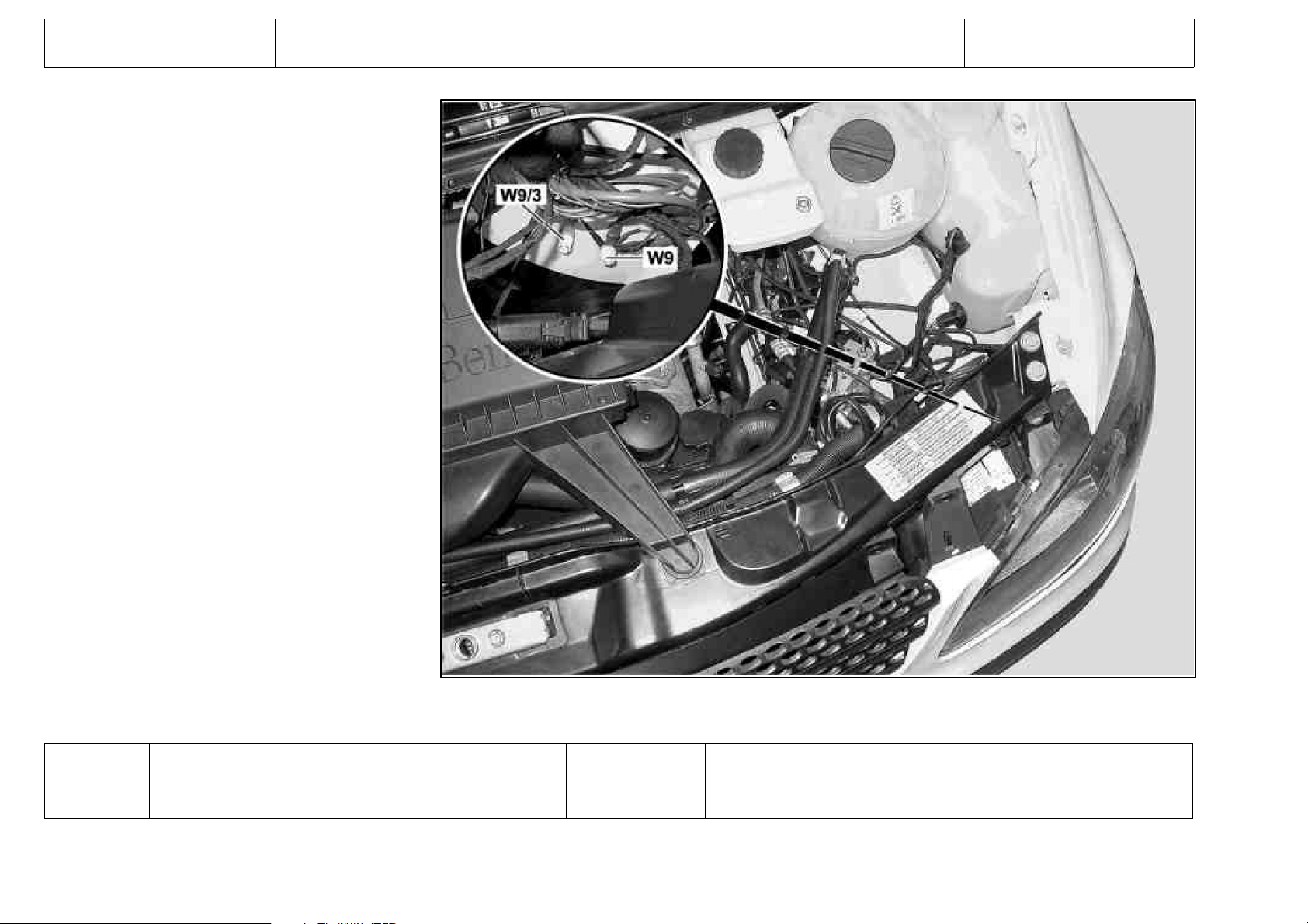
W9
Ground (left front lamp unit)
E1
E1 Lamp unit, left front
E1 Lamp unit, left front
E22/1 Additional turn signal lamp, left
K40/9 Fuse and relay block
M5/1 Windshield washer fluid pump
Lamp unit, left front
3
4
8
2
MK2.7
2
M5/2 HCS [SRA] pump
M5/3 Rear window washer fluid pump
M5/31 Rear window washer fluid pump with headlamp
cleaning system
M6/1 Windshield wiper motor
N3/9 CDI control unit
N3/9 CDI control unit
N3/9 CDI control unit
N3/10 ME control unit
N3/10 ME control unit
N3/10 ME control unit
N3/10 ME control unit
N3/20 CDI control unit
N3/20 CDI control unit
N3/20 CDI control unit
N14/2 Glow output stage
S11 Brake fluid indicator switch
S62/5 Emergency alarm system cancel button
X15 Engine fan 100 °C temperature switch connector
X25/14 O2 sensor/exhaust gas temperature sensor connector
Y19/2k1
Water valve relay
2
2
2
4
2.2
2.4
2.6
5.5
5.6
5.7
5.8
2.2
2.4
2.6
2.1
1
3
2
11
9
N30/4
W9/3
Copyright Daimler Chrysler AG 03.12.2005 CD-Aus gabe G/11/05 . This WIS print-out will not be recorded by M odification services . Page 2
Ground (left front ABS)
N30/4
ESP control unit
ESP control unit
A. 1
A. 5
Page 31

GF00.19-S-2000-02VB
Location and assignment of ground points,
engine compartment, right
Model 639
N62.20-2030-06
Ground point
Designation
Component
Designation
Con-
nector.
Pin
Copyright Daimler Chrysler AG 03.12.2005 CD-Aus gabe G/11/05 . This WIS print-out will not be recorded by M odification services . Page 1
Page 32

W2
Ground (right front lamp unit)
M13/5
E2 Lamp unit, right front
E2 Lamp unit, right front
E2 Lamp unit, right front
E22/2 Additional turn signal lamp, right
H1 Audible warning device
Heating water circulation pump
1
3
4
8
2
A
H3/1 Alarm signal horn with additional battery
K2 Headlamp cleaning system relay
K40/9 Fuse and relay block
M5/1 Windshield washer fluid pump
M5/2 HCS [SRA] pump
M5/3 Rear window washer fluid pump
M5/31 Rear window washer fluid pump with headlamp
cleaning system
N14/2 Glow output stage
N3/9 CDI control unit
N3/9 CDI control unit
N3/9 CDI control unit
N3/10 ME control unit
N3/10 ME control unit
N3/10 ME control unit
N3/10 ME control unit
N3/20 CDI control unit
N3/20 CDI control unit
N3/20 CDI control unit
S11 Brake fluid indicator switch
X25/14 O2 sensor/exhaust gas temperature sensor connector
X42/30
ATA [EDW] separation point, engine hood contact
2
4
MK2.7
2
2
2
2
2.1
2.2
2.4
2.6
5.5
5.6
5.7
5.8
2.2
2.4
2.6
1
11
2
N30/4
W2/1
Copyright Daimler Chrysler AG 03.12.2005 CD-Aus gabe G/11/05 . This WIS print-out will not be recorded by M odification services . Page 2
Ground (right front ABS)
N30/4
ESP control unit
ESP control unit
A. 1
A. 5
Page 33

GF00.19-S-2000-04VB
Arrangement and assignment of ground points interior left
Type 639
N91.10-2171-11
Ground point
Designation
Component
Designation
Con-
nector.
Pin
W10
Copyright Daimler Chrysler AG 03.12.2005 CD-Aus gabe G/11/05 . This WIS print-out will not be recorded by M odification services . Page 1
Ground (battery)
G1
Battery
2
Page 34

GF00.19-S-2000-05VB
Location and assignment of ground points,
interior compartment, right
Type 639
N91.10-2170-11
Ground point
Designation
Component
Designation
Con-
nector.
Pin
W10/4
Copyright Daimler Chrysler AG 03.12.2005 CD-Aus gabe G/11/05 . This WIS print-out will not be recorded by M odification services . Page 1
Ground (additional battery)
G1/1
Additional battery
2
Page 35

GF00.19-S-2000-21VB
Location and assignment of ground points - rearend
Type 639
N64.20-2014-11
Copyright Daimler Chrysler AG 03.12.2005 CD-Aus gabe G/11/05 . This WIS print-out will not be recorded by M odification services . Page 1
Page 36

N64.20-2015-11
Ground point
Designation
Comp-onent
Designation
Connector.
Pin
Copyright Daimler Chrysler AG 03.12.2005 CD-Aus gabe G/11/05 . This WIS print-out will not be recorded by M odification services . Page 2
Page 37

W29/8
Ground (left D-pillar)
E3
E22/3 Additional turn signal lamp, left rear
N19/3 Rear AC control unit FONDKLA
N125 Telephone high frequency compensator
S81/1 Rear heater operating switch
X8/22 Left rear-end door connector
Taillamp, left
3
A. 4
1.2
A. 4
8
W29/9
Ground (right D-pillar)
X8/23 Left rear-end door connector
X8/23 Left rear-end door connector
X52/5 Left taillamp connector
X58/4 Load compartment socket, left front
X96/5 Rear recirculation unit connector 3
Y67
A9/1
E4 Taillamp, right
E22/4 Additional turn signal lamp, right rear
H3/4 Backup warning horn
N9/1 Additional turn signal module control unit
N28/1 Trailer connection unit [AAG] control unit
N28/1 Trailer connection unit [AAG] control unit
N51/3 ENR control unit
S77 Raise/lower level adjustment switch
S77/1 Level control lock-out switch
X8/20 Right rear-end door connector
X8/20 Right rear-end door connector
X8/21 Tailgate connector
X8/21 Tailgate connector
X8/24 Pop-up roof connector (Westfalia)
X11/35 Air suspension compressor assembly connector
X20/11 Center high-mounted stop lamp connector, rear-end door
X52/6 Right taillamp connector
X58 Trailer hitch socket (13-pin)
X58 Trailer hitch socket (13-pin)
X58/12 Load compartment socket, right rear
Refrigerant shutoff valve
Air suspension compressor assembly
1
5
3
1
1
1.2
3
2
17
1.3
2.2
1.6
10
10
6
8
1
5
8
1
2
3
3
13
1
Copyright Daimler Chrysler AG 03.12.2005 CD-Aus gabe G/11/05 . This WIS print-out will not be recorded by M odification services . Page 3
Page 38

GF00.19-S-2000-24VB
Location and assignment of ground points - roof
Model 639
N65.00-2028-11
Ground point
Designation
Component
Designation
Con-
nector.
Pin
W38
Copyright Daimler Chrysler AG 03.12.2005 CD-Aus gabe G/11/05 . This WIS print-out will not be recorded by M odification services . Page 1
Ground (roof)
A50
E15 Dome lamp with reading lamp, front
E15/6 Interior lamp, left front grab handle
E15/7 Interior lamp, right front grab handle
E15/8 Interior lamp, left rear grab handle
E15/9 Interior lamp, right rear grab handle
E25/7 Transistor lamp, left
E25/8 Transistor lamp, right 2
Taximeter
8
1
A
A
A
A
2
Page 39

N70 Overhead control panel control unit
N70/1 Rear sliding roof unit control unit (SDE-H)
S62/6 Emergency alarm system activate button
S138/1 Left sun visor illumination switch
S138/2 Right sun visor illumination switch
X2/17 Antenna amplifier voltage supply connector
X2/79 TV antenna selector connector
1.2
1.2
2
2
2
1
1
X2/97 TV double amplifier 1 connector
X2/98 TV double amplifier 2 connector
X8/25 Sliding roof in pop-up roof separation point (Westfalia)
X29/17 MQS coupling (10-pin)
X41/6 Mirror taximeter separation point
Z20/62 Screening end connector sleeve
Z83/15
Shielding connector sleeve
1
1
2
8
2
Copyright Daimler Chrysler AG 03.12.2005 CD-Aus gabe G/11/05 . This WIS print-out will not be recorded by M odification services . Page 2
Page 40

GF00.19-S-2000-26VB
Location and assignment of ground points center console
Model 639
N68.20-2061-11
Copyright Daimler Chrysler AG 03.12.2005 CD-Aus gabe G/11/05 . This WIS print-out will not be recorded by M odification services . Page 1
Page 41

N68.20-2062-11
Ground point
Designation
Component
Designation
Con-
nector.
Pin
Copyright Daimler Chrysler AG 03.12.2005 CD-Aus gabe G/11/05 . This WIS print-out will not be recorded by M odification services . Page 2
Page 42

W12
Ground (cockpit and center console)
A1
A1 Instrument cluster
A2/77 Telephone and communication unit
A2/77 Telephone and communication unit
A2/78 Audio-Video-Navigation (AVN)
A35/11 SBS control unit
Instrument cluster
8
12
j8.12
j8.13
AB. A8
1.3
A35/13 D2B telephone transmitter/receiver
A45/1 Steering wheel clock spring contact
A49 Taxi two-way radio
A49/4 STH radio receiver
A56 Modular tachograph
E9/7 Illumination, front ashtray
E13/1 Glove compartment light
K23/1 Blower motor relay
N15/5 Electronic selector lever module control unit
N26/5 Electric steering lock control unit
N33/4 Heater booster control unit
N66/4 Rear conversation unit control unit
N72/1 Upper control panel control unit
N73 EIS [EZS] control unit
N123 Hands-free system control unit
R3 Front cigar lighter (with illumination)
S13/3 Taxi two-way radio/roof sign switch
S16/2 Backup lamp switch
S46/10 Stationary heater switch
S66/4 Rear entertainment system switch
S98 Air conditioning operating module
S144 Combination switch
X11 Data link connector
X11 Data link connector
X11/32 Connector between selector lever module and data link
connector
X31/12
Blower connector, terminal 31
1.3
9
1.8
6
A. 5
1
1
6
1.2
3
PTCA
1.1
1.1
B. 2
1.1
1
10
1
10
10
B. 12
4
4
5
2
MK2.7
A53
W26
Copyright Daimler Chrysler AG 03.12.2005 CD-Aus gabe G/11/05 . This WIS print-out will not be recorded by M odification services . Page 3
Ground (restraint systems control unit)
Thoraxbag and windowbag sensor, left
1
Page 43

A54 Thoraxbag and windowbag sensor, right
N2/2 SRS control unit
N2/2 SRS control unit
N2/10 SRS control unit
N2/10 SRS control unit
N2/11 ARCADE airbag control unit
N2/11 ARCADE airbag control unit
1
1.83
1.84
1.83
1.84
1.15
1.16
X28/18 Seat occupied recognition with ACSR [AKSE] connector
X55/32 Switch connector, driver seat belt buckle
X55/42
Switch connector, front passenger seat belt buckle
3
1
1
Copyright Daimler Chrysler AG 03.12.2005 CD-Aus gabe G/11/05 . This WIS print-out will not be recorded by M odification services . Page 4
Page 44

GF00.19-S-2000-25VB
Location and assignment of ground points - side
panel
Type 639
N63.00-2004-11
Ground point
Designation
Component
Designation
Con-
nector.
Pin
W33/4
Copyright Daimler Chrysler AG 03.12.2005 CD-Aus gabe G/11/05 . This WIS print-out will not be recorded by M odification services . Page 1
Ground (tank filler neck)
W43/1
Ground (left interior compartment firewall)
Page 45

GF00.19-S-2000-30VB
Location and assignment of ground points - left
firewall
Model 639
N62.25-2068-11
Ground point
Designation
Component
Designation
Con-
nector.
Pin
W43/1
Copyright Daimler Chrysler AG 03.12.2005 CD-Aus gabe G/11/05 . This WIS print-out will not be recorded by M odification services . Page 1
Ground (left interior compartment firewall)
A6n1
K40/9 Fuse and relay block
M3/3 Fuel pump with fuel level sensor
M28/11 Lumbar support adjustment motor, right
M28/12 Lumbar support adjustment motor, left
M46/1 STH fuel metering pump
N10/16 COU [ZBE] control unit 1.8
N10/16 COU [ZBE] control unit 1.25
STH control unit
1.2
I1.6
4
2
2
2
Page 46

N32/1 Left front seat adjustment control unit with memory
N32/2 Right front seat adjustment control unit with memory
N33/5 Hot air stationary heater control unit
N34 STH timer
N69/1 Door control unit, left front
S12 Parking brake indicator switch
X54/29 Heated seats connector, left front
2.2
2.2
1.10
1.4
2.4
1
1
X54/30 Heated seats connector, right front
X58/1 Interior socket
X58/17
12V socket
1
1
1
Copyright Daimler Chrysler AG 03.12.2005 CD-Aus gabe G/11/05 . This WIS print-out will not be recorded by M odification services . Page 2
Page 47

GF00.19-S-2000-34VB
Location and assignment of ground points - right
firewall
Type 639
N62.25-2067-11
Ground point
Designation
Component
Designation
Con-
nector.
Pin
W43/2
Copyright Daimler Chrysler AG 03.12.2005 CD-Aus gabe G/11/05 . This WIS print-out will not be recorded by M odification services . Page 1
Ground (right interior compartment firewall)
A6n1
B37/3 Pedal value sensor
K2 Headlamp cleaning system relay
K40/9 Fuse and relay block
M28/11 Lumbar support adjustment motor, right
M28/12 Lumbar support adjustment motor, left
N26/15 PSM control unit 2.3
N32/1 Left front seat adjustment control unit with memory 2.2
STH control unit
1.2
2.2
4
I1.6
2
2
Page 48

N32/2 Right front seat adjustment control unit with memory
N62 PTS control unit
N69/2 Door control unit, right front
S12 Parking brake indicator switch
S40/3 Clutch pedal switch
X30/27 Engine CAN bus connector
X54/29-2 Heated seats connector, left front
2.2
1.10
2.4
1
1
1.3
1
X54/30-1
Heated seats connector, right front
1
Copyright Daimler Chrysler AG 03.12.2005 CD-Aus gabe G/11/05 . This WIS print-out will not be recorded by M odification services . Page 2
Page 49

Location and assignment of plug connections Chapter 4
06/05 Transporters • Electrics <>Van - Electrical Systems
Wiring Diagrams VITO (Model 639)
Page 50

GF00.19-S-1000VB
Location and assignment of line and plug connectors 19.7.05
X1/30 Speaker connector
X8/20 Right rear-end door connector
X8/22 Left rear-end door connector
X11/32 Connector between selector lever module and
data link connector
X15 Engine fan 100 °C temperature
switch connector
X18/2 Load compartment lamp connector
X18/23 Telephone ON Telephone connector
X26/23 Engine compartment to cockpit connector
X28/23 Airbag connector, driver and front passenger
X30/24 Interior CAN bus connector
X30/27 Engine CAN bus connector
X52 Trailer hitch connector
X54/12 2-pin heated seats connector, left and right
X62/6 Rpm sensor and brake wear sensor connector,
right front
X62/7 Rpm sensor and brake wear sensor connector,
left front
X62/8 Rpm sensor and brake wear sensor connector,
left rear
X62/21 ABS/ASR rpm signal connector, left rear
X62/22 ABS/ASR rpm signal connector, right rear
X62/28 Rpm sensor connector
X62/39 BBV rear axle connector, left
X62/40 BBV rear axle connector, right
X72 STH connector
GF00.19-S-1000-05VB
GF00.19-S-1000-20VB
GF00.19-S-1000-20VB
GF00.19-S-1000-05VB
GF00.19-S-1000-33VB
GF00.19-S-1000-05VB
GF00.19-S-1000-05VB
GF00.19-S-1000-05VB
GF00.19-S-1000-28VB
GF00.19-S-1000-05VB
GF00.19-S-1000-05VB
GF00.19-S-1000-20VB
GF00.19-S-1000-05VB
GF00.19-S-1000-33VB
GF00.19-S-1000-33VB
GF00.19-S-1000-24VB
GF00.19-S-1000-24VB
GF00.19-S-1000-24VB
GF00.19-S-1000-05VB
GF00.19-S-1000-24VB
GF00.19-S-1000-24VB
GF00.19-S-1000-05VB
Copyright Daimler Chrysler AG 03.12.2005 CD-Aus gabe G/11/05 . This WIS print-out will not be recorded by M odification services . Page 1
Page 51

GF00.19-S-1000-05VB Location and assignment of line and plug
connectors, interior compartment, right
Model 639
N68.10-2199-08
Code Designation Cable colors Cable colors Notes
Copyright Daimler Chrysler AG 03.12.2005 CD-Aus gabe G/11/05 . This WIS print-out will not be recorded by M odification services . Page 1
Page 52

X1/30 Speaker connector
GY
1
GY
X11/32 Connector between selector lever module and data link
connector
X18/2 Load compartment lamp connector
X18/23 Telephone ON Telephone connector
BNGY
WH
BNWH
green
BNGN
BU
BUBN
PKYE
bn
RDWH
RD
YE
2
BNGY
3
WH
4
BNWH
5
gn
6
BNGN
7
BU
8
BUBN
1
PKYE
2
bn
1
RDWH
2
RD
1
YE
Copyright Daimler Chrysler AG 03.12.2005 CD-Aus gabe G/11/05 . This WIS print-out will not be recorded by M odification services . Page 2
Page 53

X26/23 Engine compartment to cockpit connector
GNGY
3
GNGY
GNWH
GNYE
BNBU
BURD
green
BUVT
BUWH
BUGY
YERD
YEWH
RDBU
GNYE
BKGN
BN
4
5
7
8
9
10
11
12
13
14
15
16
17
18
GNWH
GNYE
BNBU
BURD
GNWH
BU
BUWH
BUGY
YERD
YEWH
RDBU
GNYE
BKGN
BN
RDGN
BNGN
X30/24 Interior CAN bus connector
X30/27 Engine CAN bus connector
X54/12 2-pin heated seats connector, left and right
BKGY
Copyright Daimler Chrysler AG 03.12.2005 CD-Aus gabe G/11/05 . This WIS print-out will not be recorded by M odification services . Page 3
BKBU
BKVT
19
20
21
1
2
1
2
3
1
2
RDGN
BNGN
BKBU
BNRD
BN
GNWH
GN
BNYE
BKVT
BKGY
Page 54

X62/28 Rpm sensor connector
BUBN
1
BUBN
X72 STH connector
BU
YEBN
YE
VTGN
VTBK
VTYE
OG
YEGN
BUGY
2
BU
3
YEBN
4
YE
1
VTGN
2
VTBK
3
VTYE
4
OG
5
YEGN
6
BUGY
Copyright Daimler Chrysler AG 03.12.2005 CD-Aus gabe G/11/05 . This WIS print-out will not be recorded by M odification services . Page 4
Page 55

GF00.19-S-1000-20VB Location and assignment of line and plug
connectors - rear
Model 639
N68.30-2073-12
Code Designation Cable colors Cable colors Notes
Copyright Daimler Chrysler AG 03.12.2005 CD-Aus gabe G/11/05 . This WIS print-out will not be recorded by M odification services . Page 1
Page 56

X8/20 Right rear-end door connector
BURD
1
BURD
X8/22 Left rear-end door connector
X52 Trailer hitch connector
BUBK
BUWH
BUGN
BKYE
BN
GYGN
BN
BUWH
GYGN
BN
BUGN
BUWH
BKBN
2
3
4
5
6
7
8
10
7
8
9
10
1
BUBK
BUWH
BUGN
BKYE
BN
GYGN
BN
BUWH
GYGN
BN
BUGN
BUWH
BKBN
BKRD
RDYE
BNBU
Copyright Daimler Chrysler AG 03.12.2005 CD-Aus gabe G/11/05 . This WIS print-out will not be recorded by M odification services . Page 2
BN
2
BKRD
3
RDYE
4
BNBU
5
BN
Page 57

GF00.19-S-1000-24VB Location and assignment of line and plug Model 639
connectors - underfloor
Shown on left side of vehicle
S54.18-4517-05
Copyright DaimlerChrysler AG 12/3/05 G/11/05. This WIS printout will not be recorded by the update service. Page 1
Page 58

Illustrated on right side of vehicle
S35.00-4510-06
Code Designation Notes
X62/8 1Rpm sensor and brake wear sensor connector, left rear
Copyright DaimlerChrysler AG 12/3/05 G/11/05. This WIS printout will not be recorded by the update service. Page 2
Cable colors Cable colors
BK GNRD
WH GNBN
WH BU
2
1
Page 59

BK BUBN
WH YE
BK YEBN
BK green
WH GNRD
2
1
2
1
2
X62/21 1ABS/ASR rpm signal connector, left rear
X62/22 1ABS/ASR rpm signal connector, right rear
X62/39 1BBV rear axle connector, left
X62/40 1
BBV rear axle connector, right
WH YE
BK YEBN
WH BU
BK BUBN
BK GN
WH GNRD
BK GNRD
WH GNBN
2
2
2
2
Copyright DaimlerChrysler AG 12/3/05 G/11/05. This WIS printout will not be recorded by the update service. Page 3
Page 60

GF00.19-S-1000-28VB Location and assignment of line and plug Model 639
connectors - center console
Code Designation Notes
X28/23 1
Copyright DaimlerChrysler AG 12/3/05 G/11/05. This WIS printout will not be recorded by the update service. Page 1
Airbag connector, driver and front passenger
Cable colors Cable colors
VT VT
GN GN
BUGN BUGN
BNBK BNBK
2
3
4
Page 61

N01.00-2432-06
Code Designation Notes
X15 1Engine fan 100 °C temperature switch connector
Copyright DaimlerChrysler AG 12/3/05 G/11/05. This WIS printout will not be recorded by the update service. Page 2
Cable colors Cable colors
RD RD
BN BN
BUVT BU
2
3
Page 62

BUWH BUWH
4
X62/6 1
X62/7 1Rpm sensor and brake wear sensor connector, left front
Rpm sensor and brake wear sensor connector, right
front
WH WH
BK WHYE
BK
WH
WH BK
BK BKYE
BK
WH
2
1
2
3
4
2
1
2
3
4
YEVT
VTGN
VTWH
YEVT
Copyright DaimlerChrysler AG 12/3/05 G/11/05. This WIS printout will not be recorded by the update service. Page 3
Page 63

Battery, starting charging circuit Chapter 5
06/05 Transporters • Electrics <>Van - Electrical Systems
Wiring Diagrams VITO (Model 639)
Page 64

PE15.00-S-2000VA
Wiring diagram for starter, alternator 25.3.03
ENGINES 646.982 /983, 112.951 /976, 642.990 up to 28.2.05 in MODELS 639.601 /603 /605 /701 /703 /705 up to 28.2.05
ENGINES 646.982, 112.951 /976, 642.990 up to 28.2.05 in MODELS 639.711 /713 /811 /813 /815 up to 28.2.05
PE15.00-S-2000-99VA Wiring diagram for starter, alternator
PE15.00-S-2000-60VA Legend of wiring diagram for starter, alternator
OV00.01-S-1901-03VA Use of wiring diagrams
OV00.01-S-1901VA Search aid for all wiring diagram groups
OV00.01-S-1909VA Search aid for all electrical components Components from A to E
OV00.01-S-1909VB Search aid for all electrical components Components from F to J
OV00.01-S-1909VC Search aid for all electrical components Components from K to O
OV00.01-S-1909VD Search aid for all electrical components Components from P to T
OV00.01-S-1909VE Search aid for all electrical components Components from U to Z
OV00.01-S-1001-27VA Abbreviations for wiring diagrams
OV00.01-S-1001-28VA Abbreviations of signal and circuit designations
for wiring diagrams
GF00.19-S-1000VB Location and assignment of line and plug
connectors
GF00.19-S-1100VB Location and assignment of connectors and
sockets
GF00.19-S-2000VB Location and assignment of ground points
GF00.19-S-3000VB Location and assignment of Z connector sleeves
(line connectors in wiring harness)
GF54.15-S-0900VA Fuse and relay box - location/assignment
PE15.00-S-2000-99VA
PE15.00-S-2000-60VA
OV00.01-S-1901-03VA
OV00.01-S-1901VA
OV00.01-S-1909VA
OV00.01-S-1909VB
OV00.01-S-1909VC
OV00.01-S-1909VD
OV00.01-S-1909VE
OV00.01-S-1001-27VA
OV00.01-S-1001-28VA
GF00.19-S-1000VB
GF00.19-S-1100VB
GF00.19-S-2000VB
GF00.19-S-3000VB
GF54.15-S-0900VA
Copyright Daimler Chrysler AG 03.12.2005 CD-Aus gabe G/11/05 . This WIS print-out will not be recorded by M odification services . Page 1
Page 65

PE15.00-S-2000-60VA Legend of wiring diagram for starter, alternator ENGINES 646.982 /983, 112.951 /976,
642.990 up to 28.2.05 in
MODELS 639.601 /603 /605/
701 /703 /705 up to 28.2.05
ENGINES 646.982, 112.951 /976, 642.990
up to 28.2.05 in MODELS
639.711 /713 /811/ 813 /815 up
to 28.2.05
Code Designation Coordinates
A0 Color code key 48L
F1 1-pin prefuse box 12G
F4 Fuse box (1-pin) 27L
F5 Fuse box (1-pin) 24L
F34 Fuse block, 22-pin 29K
F35 Fuse block, 22-pin 32L
G1 Battery 12K
G2/2 Alternator 40A
G2/5 200 A Alternator 4A
K40/9 Fuse and relay block 2K
9K
19K
21K
39K
M1 Starter 10A
N3/9 CDI control unit 5K
N14/2 Glow output stage 34K
N33/4 Heater booster control unit 16K
U53 Valid for automatic air conditioning "Thermotronic" 26H
U54 Valid for regulated air conditioning "Tempmatic" 26H
U1001 Valid for engine OM 646 with automatic transmission 1A
U1002 Valid for PTC element 16H
Copyright Daimler Chrysler AG 03.12.2005 CD-Aus gabe G/11/05 . This WIS print-out will not be recorded by M odification services . Page 1
Page 66

U1080 Valid for alternator 14V / 200 A without automatic transmission 41F
U150 Valid for engine M 112 24H
37B
U740 Valid for engine OM 646 34H
U999 Valid for engine OM 646 without automatic transmission 37A
X22 Engine compartment and engine connector 3H
Z66/1 Additional fuse box feed connector sleeve 30F
Copyright Daimler Chrysler AG 03.12.2005 CD-Aus gabe G/11/05 . This WIS print-out will not be recorded by M odification services . Page 2
Page 67

Copyright Daimler Chrysler AG 03.12.2005 CD-Aus gabe G/11/05 . This WIS print-out will not be recorded by M odification services . Page 1
Page 68

Copyright Daimler Chrysler AG 03.12.2005 CD-Aus gabe G/11/05 . This WIS print-out will not be recorded by M odification services . Page 2
Page 69

Copyright Daimler Chrysler AG 03.12.2005 CD-Aus gabe G/11/05 . This WIS print-out will not be recorded by M odification services . Page 3
Page 70

PE15.00-S-2000VB
Wiring diagram for starter, alternator 24.8.05
ENGINES 646.982 /983, 112.951 /976, 642.990 as of 1.3.05 in MODELS 639.601 /603 /605 /701 /703 /705 as of 1.3.05
ENGINES 646.982, 112.951 /976, 642.990 as of 1.3.05 in MODELS 639.711 /713 /811 /813 /815 as of 1.3.05
PE15.00-S-2000-99VB Wiring diagram for starter, alternator
PE15.00-S-2000-60VB Legend of wiring diagram for starter, alternator
OV00.01-S-1901-03VA Use of wiring diagrams
OV00.01-S-1901VA Search aid for all wiring diagram groups
OV00.01-S-1909VA Search aid for all electrical components Components from A to E
OV00.01-S-1909VB Search aid for all electrical components Components from F to J
OV00.01-S-1909VC Search aid for all electrical components Components from K to O
OV00.01-S-1909VD Search aid for all electrical components Components from P to T
OV00.01-S-1909VE Search aid for all electrical components Components from U to Z
OV00.01-S-1001-27VA Abbreviations for wiring diagrams
OV00.01-S-1001-28VA Abbreviations of signal and circuit designations
for wiring diagrams
GF00.19-S-1000VB Location and assignment of line and plug
connectors
GF00.19-S-1100VB Location and assignment of connectors and
sockets
GF00.19-S-2000VB Location and assignment of ground points
GF00.19-S-3000VB Location and assignment of Z connector sleeves
(line connectors in wiring harness)
GF54.15-S-0900VA Fuse and relay box - location/assignment
PE15.00-S-2000-99VB
PE15.00-S-2000-60VB
OV00.01-S-1901-03VA
OV00.01-S-1901VA
OV00.01-S-1909VA
OV00.01-S-1909VB
OV00.01-S-1909VC
OV00.01-S-1909VD
OV00.01-S-1909VE
OV00.01-S-1001-27VA
OV00.01-S-1001-28VA
GF00.19-S-1000VB
GF00.19-S-1100VB
GF00.19-S-2000VB
GF00.19-S-3000VB
GF54.15-S-0900VA
Copyright Daimler Chrysler AG 03.12.2005 CD-Aus gabe G/11/05 . This WIS print-out will not be recorded by M odification services . Page 1
Page 71

PE15.00-S-2000-60VB Legend of wiring diagram for starter, alternator ENGINES 646.982 /983, 112.951 /976,
642.990 from 1.3.05 in
MODELS 639.601 /603 /605/
701 /703 /705 from 1.3.05
ENGINES 646.982, 112.951 /976, 642.990
from 1.3.05 in MODELS
639.711 /713 /811/ 813 /815
from 1.3.05
Code Designation Coordinates
A0 Color code key 64L
F1 1-pin prefuse box 31G
F4 Fuse box (1-pin) 53K
F5 Fuse box (1-pin) 50K
F34 Fuse block, 22-pin 42K
F35 Fuse block, 22-pin 44K
G1 Battery 35K
G2/2 Alternator 24B
G2/5 200 A Alternator 17B
G2/6 Alternator 200 A with LIN bus 4B
K40/9 Fuse and relay block 8K
15K
22K
29K
37K
40K
M1 Starter 29A
N3/9 CDI control unit 18K
N3/20 CDI control unit 3L
N14/2 Glow output stage 58K
N14/3 Glow output stage 11L
55K
Copyright Daimler Chrysler AG 03.12.2005 CD-Aus gabe G/11/05 . This WIS print-out will not be recorded by M odification services . Page 1
Page 72

N33/4 Heater booster control unit 47L
U53 Valid for automatic air conditioning "Thermotronic" 52H
U54 Valid for regulated air conditioning "Tempmatic" 52H
U1001 Valid for engine OM 646 with automatic transmission 15B
U1002 Valid for PTC element 47H
U1080 Valid for alternator 14V / 200 A without automatic transmission 23G
U150 Valid for engine M 112 21B
50H
U740 Valid for engine OM 646 58H
U960 Valid for engine OM 642 1B
55H
U999 Valid for engine OM 646 without automatic transmission 21B
X22 Engine compartment and engine connector 16H
Z66/1 Additional fuse box feed connector sleeve 43G
Z203/3 Alternator connector sleeve 3H
Copyright Daimler Chrysler AG 03.12.2005 CD-Aus gabe G/11/05 . This WIS print-out will not be recorded by M odification services . Page 2
Page 73

Copyright Daimler Chrysler AG 03.12.2005 CD-Aus gabe G/11/05 . This WIS print-out will not be recorded by M odification services . Page 1
Page 74

Copyright Daimler Chrysler AG 03.12.2005 CD-Aus gabe G/11/05 . This WIS print-out will not be recorded by M odification services . Page 2
Page 75

Copyright Daimler Chrysler AG 03.12.2005 CD-Aus gabe G/11/05 . This WIS print-out will not be recorded by M odification services . Page 3
Page 76

Copyright Daimler Chrysler AG 03.12.2005 CD-Aus gabe G/11/05 . This WIS print-out will not be recorded by M odification services . Page 4
Page 77

Voltage supply fuses Chapter 6
06/05 Transporters • Electrics <>Van - Electrical Systems
Wiring Diagrams VITO (Model 639)
Page 78

PE54.15-S-2005VA
Wiring diagram of voltage supply of fuses 25.3.03
MODEL 639.601 /603 /605 /701 /703 /705 /711 /713 /811 /813 /815
left seat frame
PE54.15-S-2005-99VA Wiring diagram of voltage supply of fuses
PE54.15-S-2005-60VA Legend of wiring diagram for voltage supply of
fuses
OV00.01-S-1901-03VA Use of wiring diagrams
OV00.01-S-1901VA Search aid for all wiring diagram groups
OV00.01-S-1909VA Search aid for all electrical components Components from A to E
OV00.01-S-1909VB Search aid for all electrical components Components from F to J
OV00.01-S-1909VC Search aid for all electrical components Components from K to O
OV00.01-S-1909VD Search aid for all electrical components Components from P to T
OV00.01-S-1909VE Search aid for all electrical components Components from U to Z
OV00.01-S-1001-27VA Abbreviations for wiring diagrams
OV00.01-S-1001-28VA Abbreviations of signal and circuit designations
for wiring diagrams
GF00.19-S-1000VB Location and assignment of line and plug
connectors
GF00.19-S-1100VB Location and assignment of connectors and
sockets
GF00.19-S-2000VB Location and assignment of ground points
GF00.19-S-3000VB Location and assignment of Z connector sleeves
(line connectors in wiring harness)
GF54.15-S-0900VA Fuse and relay box, location/assignment
PE54.15-S-2005-99VA
PE54.15-S-2005-60VA
OV00.01-S-1901-03VA
OV00.01-S-1901VA
OV00.01-S-1909VA
OV00.01-S-1909VB
OV00.01-S-1909VC
OV00.01-S-1909VD
OV00.01-S-1909VE
OV00.01-S-1001-27VA
OV00.01-S-1001-28VA
GF00.19-S-1000VB
GF00.19-S-1100VB
GF00.19-S-2000VB
GF00.19-S-3000VB
GF54.15-S-0900VA
Copyright Daimler Chrysler AG 03.12.2005 CD-Aus gabe G/11/05 . This WIS print-out will not be recorded by M odification services . Page 1
Page 79

PE54.15-S-2005-60VA Legend of wiring diagram for voltage supply of
fuses
MODEL 639.601 /603 /605 /701 /703
/705 /711 /713 /811 /813 /815
left seat frame
Code Designation Coordinates
E25/7 Transistor lamp, left 24K
E25/8 Transistor lamp, right 27K
F6 Fuse box (1-pin) 3E
F7 Fuse block (9-pin) 6E
F7-b1 Fuse connector (2-pin) 7D
F7-b2 Fuse connector (2-pin) 12D
F7-b3 Fuse connector (2-pin) 17D
F7-b4 Fuse connector (2-pin) 22D
F7-b5 Fuse connector (1-pin) 34D
F7f1 Left door control unit fuse 7D
F7f2 Right door control unit fuse 9D
F7f3 Fuse 1 (PSM) 12D
F7f4 Fuse 2 (PSM) 14D
F7f5 12V socket fuse, front passenger seat box 17D
F7f6 Charge line to vehicle battery fuse 20D
F7f7 Timer and illumination power supply fuse 22D
F7f8 STH power supply fuse 30D
F7f9 Pop-up roof power supply fuse 34D
G1 Battery 1E
G1/1 Additional battery 37E
K40/9 Fuse and relay block 3K
N26/15 PSM control unit 12K
N33/5 Hot air stationary heater control unit 30K
Copyright Daimler Chrysler AG 03.12.2005 CD-Aus gabe G/11/05 . This WIS print-out will not be recorded by M odification services . Page 1
Page 80

N34 STH timer 22K
N69/1 Door control unit, left front 6K
N69/2 Door control unit, right front 9K
U26 Valid for taxi version with emergency alarm system 11G
U27 Valid for taxi version without emergency alarm system 11G
U1025 Valid for warm air auxiliary heater with timer and temperature control 29G
U1036 Valid for freezer vehicle 11H
U1037 Valid for refrigerator vehicle 11H
U1038 Valid for FUN equipment line with refrigerator box 16G
19B
U1039 Valid for warm air auxiliary heater with timer and temperature control with FUN equipment line or comfort plus
21G
package
U1040 Valid for FUN equipment line or comfort plus package without additional heavy-duty battery 29B
U1041 Valid for FUN equipment line or comfort plus package with heavy-duty battery in addition or for "Marco Polo"
31B
camper
U1042 Valid for electrohydraulic "Easy up" pop-up roof without heavy-duty battery in addition 33B
U1043 Valid for electrohydraulic "Easy up" pop-up roof with heavy-duty battery in addition or gel additional battery 12V
35B
80Ah
U914 Valid for rental vehicle package with emergency alarm system 11H
U934 Valid for rental vehicle package without emergency alarm system 11J
U947 Valid for parameterizable special module 11G
14C
U953 Valid for electrohydraulic "Easy up" pop-up roof 11G
34G
U978 Valid for FUN equipment line 24G
U980 Valid for "Marco Polo" camper 19G
20B
24G
W10 Ground (battery) 2L
W10/4 Ground (additional battery) 37L
X8/24 Pop-up roof connector (Westfalia) 34L
X8/29 Separation point 2 (Westfalia) 20L
X58/17 12V socket 16K
Copyright Daimler Chrysler AG 03.12.2005 CD-Aus gabe G/11/05 . This WIS print-out will not be recorded by M odification services . Page 2
Page 81

Copyright Daimler Chrysler AG 03.12.2005 CD-Aus gabe G/11/05 . This WIS print-out will not be recorded by M odification services . Page 1
Page 82

Copyright Daimler Chrysler AG 03.12.2005 CD-Aus gabe G/11/05 . This WIS print-out will not be recorded by M odification services . Page 2
Page 83

Copyright Daimler Chrysler AG 03.12.2005 CD-Aus gabe G/11/05 . This WIS print-out will not be recorded by M odification services . Page 3
Page 84

PE54.15-S-2005VB
Wiring diagram of voltage supply of fuses 25.7.03
MODEL 639.601 /603 /605 /701 /703 /705 /711 /713 /811 /813 /815
Sheet 1,
E-box F34
PE54.15-S-2005-99VB Wiring diagram of voltage supply of fuses Sheet 1
PE54.15-S-2005-60VB Legend of wiring diagram for voltage supply of
fuses
OV00.01-S-1901-03VA Use of wiring diagrams
OV00.01-S-1901VA Search aid for all wiring diagram groups
OV00.01-S-1909VA Search aid for all electrical components Components from A to E
OV00.01-S-1909VB Search aid for all electrical components Components from F to J
OV00.01-S-1909VC Search aid for all electrical components Components from K to O
OV00.01-S-1909VD Search aid for all electrical components Components from P to T
OV00.01-S-1909VE Search aid for all electrical components Components from U to Z
OV00.01-S-1001-27VA Abbreviations for wiring diagrams
OV00.01-S-1001-28VA Abbreviations of signal and circuit designations
for wiring diagrams
GF00.19-S-1000VB Location and assignment of line and plug
connectors
GF00.19-S-1100VB Location and assignment of connectors and
sockets
GF00.19-S-2000VB Location and assignment of ground points
GF00.19-S-3000VB Location and assignment of Z connector sleeves
(line connectors in wiring harness)
GF54.15-S-0900VA Fuse and relay box, location/assignment
Sheet 1
PE54.15-S-2005-99VB
PE54.15-S-2005-60VB
OV00.01-S-1901-03VA
OV00.01-S-1901VA
OV00.01-S-1909VA
OV00.01-S-1909VB
OV00.01-S-1909VC
OV00.01-S-1909VD
OV00.01-S-1909VE
OV00.01-S-1001-27VA
OV00.01-S-1001-28VA
GF00.19-S-1000VB
GF00.19-S-1100VB
GF00.19-S-2000VB
GF00.19-S-3000VB
GF54.15-S-0900VA
Copyright Daimler Chrysler AG 03.12.2005 CD-Aus gabe G/11/05 . This WIS print-out will not be recorded by M odification services . Page 1
Page 85

PE54.15-S-2005-60VB Legend of wiring diagram for voltage supply of
fuses
MODEL 639.601 /603 /605 /701 /703
/705 /711 /713 /811 /813 /815
Sheet 1,
E-box F34
Code Designation Coordinates
A49/4 STH radio receiver 69K
E15 Dome lamp with reading lamp, front 54K
E15/3 Dome lamp, front of rear 50K
E15/4 Dome lamp, rear of rear 48K
E15/6 Interior lamp, left front grab handle 37K
E15/7 Interior lamp, right front grab handle 39K
E15/8 Interior lamp, left rear grab handle 42K
E15/9 Interior lamp, right rear grab handle 45K
E15/29 Load compartment lamp 1, right 20K
30K
E15/30 Load compartment lamp 2, left 23K
33K
E18/1 Trunk lamp 17K
27K
F34 Fuse block, 22-pin 6C
F34f21 Exterior lamp switch fuse 7B
F34f22 TV console fuse 11B
F34f23 Interior lamps fuse 37B
F34f24 SHD overhead control panel fuse 58B
F34f25 Rear sliding roof fuse 64B
F34f26 STH radio receiver fuse 69B
F34f27 Front climate control fuse 73B
F34f28 Socket fuse, TV console 76B
Copyright Daimler Chrysler AG 03.12.2005 CD-Aus gabe G/11/05 . This WIS print-out will not be recorded by M odification services . Page 1
Page 86

N66/4 Rear conversation unit control unit 13K
75K
N70 Overhead control panel control unit 58K
N70/1 Rear sliding roof unit control unit (SDE-H) 65K
N72/1 Upper control panel control unit 6K
S1 Exterior lamp switch 4K
S66/4 Rear entertainment system switch 11K
S98 Air conditioning operating module 72K
U15 Valid for screen in rear and DVD player 11D
75D
U16 Valid for screen in rear, DVD player and TV tuner 11E
75E
U37 Valid for ATA [EDW] I 57E
U38 Valid for ATA [EDW] II 57E
U53 Valid for automatic air conditioning "Thermotronic" 72D
U54 Valid for regulated air conditioning "Tempmatic" 72E
U1003 Valid for additional interior lamp in passenger compartment 26E
36G
U1004 Valid for interior lamp in rear 26E
47G
U1005 Valid without additional interior lamp in passenger compartment 16E
U1006 Valid without interior lamp in rear 16E
20G
30G
U1007 Valid for additional interior lamp in load compartment without interior lamp in rear 23G
33G
U1009 Valid for light/rain sensor 57E
U1011 Valid without glass tilting/sliding roof in passenger compartment 53G
U1012 Valid without glass tilting/sliding roof in driver/passenger compartment 53G
U1013 Valid without anti-theft alarm system with interior protection (EDW II) 53G
U1014 Valid for warm water auxiliary heater with radio remote control 68D
U1015 Valid for glass tilting/sliding roof in passenger compartment and roof and rear-end doors, high version 65E
U1016 Valid for glass tilting/sliding roof in passenger compartment without roof and rear-end doors, high version 65D
Copyright Daimler Chrysler AG 03.12.2005 CD-Aus gabe G/11/05 . This WIS print-out will not be recorded by M odification services . Page 2
Page 87

U1017 Valid for electrohydraulic "Easy up" pop-up roof and glass sliding/lifting roof in driver area/front passenger area 62D
U1018 Valid without EDW I 53H
U1019 Valid without light/rain sensor 53H
U1024 Valid for DBE with 2 reading spotlights or garage door opener without glass tilting/sliding roof in
59D
driver/passenger compartment, glass tilting/sliding roof in passenger compartment, light/rain sensor, EDW II or
EDW I
U949 Valid for glass tilting/sliding roof in passenger compartment 57E
U954 Valid for glass tilting/sliding roof in driver/passenger compartment 57D
U955 Valid for alternator 14V / 200 Ah 72E
U978 Valid for FUN equipment line 17G
27G
36G
U980 Valid for "Marco Polo" camper 17H
27H
36G
U982 Valid for MPV 17G
27G
U983 Valid for TREND equipment line 17G
27G
U984 Valid for AMBIENTE equipment line 17H
27H
U987 Valid without DBE with 2 reading spotlights 53H
W29/9 Ground (right D-pillar) 62L
X8/25 Sliding roof in pop-up roof separation point (Westfalia) 63L
X18/2 Load compartment lamp connector 21F
30F
Z4/1 Ceiling illumination terminal 30 connector sleeve 41G
49G
54G
Z66/1 Additional fuse box feed connector sleeve 1G
Copyright Daimler Chrysler AG 03.12.2005 CD-Aus gabe G/11/05 . This WIS print-out will not be recorded by M odification services . Page 3
Page 88

Copyright Daimler Chrysler AG 03.12.2005 CD-Aus gabe G/11/05 . This WIS print-out will not be recorded by M odification services . Page 1
Page 89

Copyright Daimler Chrysler AG 03.12.2005 CD-Aus gabe G/11/05 . This WIS print-out will not be recorded by M odification services . Page 2
Page 90

Copyright Daimler Chrysler AG 03.12.2005 CD-Aus gabe G/11/05 . This WIS print-out will not be recorded by M odification services . Page 3
Page 91

Copyright Daimler Chrysler AG 03.12.2005 CD-Aus gabe G/11/05 . This WIS print-out will not be recorded by M odification services . Page 4
Page 92

Copyright Daimler Chrysler AG 03.12.2005 CD-Aus gabe G/11/05 . This WIS print-out will not be recorded by M odification services . Page 5
Page 93

PE54.15-S-2005VC
Wiring diagram of voltage supply of fuses 25.7.03
MODEL 639.601 /603 /605 /701 /703 /705 /711 /713 /811 /813 /815
Sheet 2,
E-box F34
PE54.15-S-2005-99VC Wiring diagram of voltage supply of fuses Sheet 2
PE54.15-S-2005-60VC Legend of wiring diagram for voltage supply of
fuses
OV00.01-S-1901-03VA Use of wiring diagrams
OV00.01-S-1901VA Search aid for all wiring diagram groups
OV00.01-S-1909VA Search aid for all electrical components Components from A to E
OV00.01-S-1909VB Search aid for all electrical components Components from F to J
OV00.01-S-1909VC Search aid for all electrical components Components from K to O
OV00.01-S-1909VD Search aid for all electrical components Components from P to T
OV00.01-S-1909VE Search aid for all electrical components Components from U to Z
OV00.01-S-1001-27VA Abbreviations for wiring diagrams
OV00.01-S-1001-28VA Abbreviations of signal and circuit designations
for wiring diagrams
GF00.19-S-1000VB Location and assignment of line and plug
connectors
GF00.19-S-1100VB Location and assignment of connectors and
sockets
GF00.19-S-2000VB Location and assignment of ground points
GF00.19-S-3000VB Location and assignment of Z connector sleeves
(line connectors in wiring harness)
GF54.15-S-0900VA Fuse and relay box, location/assignment
Sheet 2
PE54.15-S-2005-99VC
PE54.15-S-2005-60VC
OV00.01-S-1901-03VA
OV00.01-S-1901VA
OV00.01-S-1909VA
OV00.01-S-1909VB
OV00.01-S-1909VC
OV00.01-S-1909VD
OV00.01-S-1909VE
OV00.01-S-1001-27VA
OV00.01-S-1001-28VA
GF00.19-S-1000VB
GF00.19-S-1100VB
GF00.19-S-2000VB
GF00.19-S-3000VB
GF54.15-S-0900VA
Copyright Daimler Chrysler AG 03.12.2005 CD-Aus gabe G/11/05 . This WIS print-out will not be recorded by M odification services . Page 1
Page 94

PE54.15-S-2005-60VC Legend of wiring diagram for voltage supply of
fuses
MODEL 639.601 /603 /605 /701 /703
/705 /711 /713 /811 /813 /815
Sheet 2,
E-box F34
Code Designation Coordinates
A0 Color code key 72L
A2 Radio / Sound 10 / Sound 40 / Audio 10 58K
61K
64K
A2/56 Radio and navigation unit 54K
A2/78 Audio-Video-Navigation (AVN) 51K
A35/11 SBS control unit 4L
A35/13 Telephone transmitter/receiver, D2B 7L
A40/3 COMAND operating, display and control unit 48L
A56 Modular tachograph 17K
F34 Fuse block, 22-pin 7C
F34f29 D2BPortable CTEL fuse, portable CTEL and SBS 8B
F34f30 Heated seats fuse 14B
F34f31 Fuse, tachograph 18B
F34f32 Fuse 32 20B
F34f33 Data link connector fuse 23B
F34f34 Fuse 34 24B
F34f35 Air conditioning pulsed valve power supply fuse 26B
F34f36 SRA fuse 27B
F34f37 ATA [EDW] siren fuse 30B
F34f38 EIS [EZS] steering lock fuse 33B
F34f39 Front blower fuse 36B
F34f40 Brake system valve fuse 45B
Copyright Daimler Chrysler AG 03.12.2005 CD-Aus gabe G/11/05 . This WIS print-out will not be recorded by M odification services . Page 1
Page 95

F34f41 Brake system delivery pump fuse 46B
F34f42 Radio fuse or DIN navigation 57B
H3/1 Alarm signal horn with additional battery 30K
K2 Headlamp cleaning system relay 27K
K23/1 Blower motor relay 41L
N30/4 ESP control unit 45K
N72/1 Upper control panel control unit 14K
N73 EIS [EZS] control unit 33K
N123 Hands-free system control unit 10L
S98 Air conditioning operating module 36L
U10 Valid for Sound 40 Pro radio 64D
U11 Valid for radio with cassette drive, Latin America 61E
U13 Valid for auto pilot system with TMC interface 48D
U38 Valid for ATA [EDW] II 30D
U51 Valid for telephone preinstallation 10D
U52 Valid for voice control 4D
U53 Valid for automatic air conditioning "Thermotronic" 38G
U55 Not valid for air conditioning 35G
U285 Valid for partially electric seat adjustment, driver 14E
U286 Valid for partially electric seat adjustment, front passenger 14E
U507 Valid for Electronic Stability Program (ESP) 45D
U909 Valid for radio preinstallation 67D
U910 Valid for radio Sound 10 with cassette drive 57D
U913 Valid for networked telephone preinstallation 7D
U922 Valid for heater for front passenger seat 14D
U923 Valid for heater for driver seat 14D
U928 Valid for headlamp cleaning system 27D
U956 Valid for auto pilot system for Japan, large display 51D
U957 Valid for Audio 10 radio with cassette drive 61D
U958 Valid for Audio 10 radio with CD 61E
Copyright Daimler Chrysler AG 03.12.2005 CD-Aus gabe G/11/05 . This WIS print-out will not be recorded by M odification services . Page 2
Page 96

U959 Valid for Audio 30 APS radio with TMC interface 54D
U968 Valid for 1 day/2 driver tachograph 17D
U998 Valid for auxiliary heater without air conditioning system 41G
W12 Ground (cockpit and center console) 20L
X31/9 Blower switch feed-in connector 36F
Z66/1 Additional fuse box feed connector sleeve 2G
Z151/3 A/C 1st stage connector sleeve 39H
Copyright Daimler Chrysler AG 03.12.2005 CD-Aus gabe G/11/05 . This WIS print-out will not be recorded by M odification services . Page 3
Page 97

Copyright Daimler Chrysler AG 03.12.2005 CD-Aus gabe G/11/05 . This WIS print-out will not be recorded by M odification services . Page 1
Page 98

Copyright Daimler Chrysler AG 03.12.2005 CD-Aus gabe G/11/05 . This WIS print-out will not be recorded by M odification services . Page 2
Page 99

Copyright Daimler Chrysler AG 03.12.2005 CD-Aus gabe G/11/05 . This WIS print-out will not be recorded by M odification services . Page 3
Page 100

Copyright Daimler Chrysler AG 03.12.2005 CD-Aus gabe G/11/05 . This WIS print-out will not be recorded by M odification services . Page 4
 Loading...