

Page 1
Operating Instructions
Vito
Nur fuer internen Gebrauch
Page 2

Symbols
G Warning
H Environmental note
! Possible vehicle damage
i Tip
E Action required
ee Continuation symbol
e page) Page reference
(
Display On-board computer display
The illustrations in these Operating Instructions apply to a left-hand-drive vehicle. In particular, the layout of switches,
levers, stowage compartments, etc., differs accordingly on right-hand-drive vehicles.
The layout of switches and the location of
indicator and warning lamps may vary
and/or individual indicator and warning
lamps may be deactivated depending on
your vehicle's equipment.
The vehicle can be equipped with version A or version B of the instrument
cluster.
Nur fuer internen Gebrauch
Page 3

Thank you for choosing MercedesBenz.
Please familiarise yourself with your vehicle, its operation and the driving, control
and convenience functions.
Please read the Operating Instructions before starting your first journey. This will
help you to get more enjoyment from your
vehicle and avoid endangering yourself
and others.
The equipment in the vehicle may differ
from some of the descriptions and illustrations you see here as the scope of delivery
depends on the equipment ordered. These
Operating Instructions also describe items
of equipment available as optional extras,
if their operation needs explanation.
Country-specific vehicle equipment,
limited availability of optional equipment
or different product designations are possible in certain countries.
DaimlerChrysler reserves the right to
change the design, equipment and technical features. For this reason, no claims
may be based on the data, illustrations or
descriptions contained in these Operating
Instructions.
If you have any further questions, your
nearest Mercedes-Benz Service Centre will
be pleased to assist you.
The Operating Instructions, Brief Instructions, Maintenance Booklet and any Equipment Supplements are an integral part of
the vehicle. You should therefore always
keep them in the vehicle and pass them
on to the new owner if you sell the vehicle.
The technical documentation team at
DaimlerChrysler AG wishes you safe and
pleasant motoring.
Nur fuer internen Gebrauch
Page 4

Contents
Keywords
Introduction
Protection of the environment. . ..... 15
Operating safety and vehicle approval. 16
1 At a glance
Cockpit ........................ 20
Instrument cluster versions......... 22
Steering wheel with buttons . . . ..... 29
Centre console .................. 30
Switch units . . ................... 31
2 Safety
Occupant safety. ................. 36
General safety notes . . ............ 55
Tyres and wheels ................. 56
3 Controls
Opening and closing . . ............ 62
Anti-theft systems ................ 79
Seats .......................... 81
Steering wheel................... 97
Mirrors......................... 97
Instrument cluster ................ 99
On-board computer without steering
wheel buttons - version A ......... 102
On-board computer with steering
wheel buttons - version A ......... 104
On-board computer without steering
wheel buttons - version B ......... 118
On-board computer with steering
wheel buttons - version B ......... 120
Lighting ....................... 138
Good visibility .................. 144
Climate control ................. 147
Driving and parking . . . ........... 171
Braking ....................... 177
Shifting gears. .................. 179
Operating the vehicle. . ........... 182
Driving systems ................. 188
Level control . .................. 198
Features....................... 200
Communications ................ 208
4 Operation
Driving tips . . .................. 212
Refuelling...................... 215
Transporting loads with the vehicle . . 217
Winter driving .................. 235
Service products ................ 237
Cleaning and care ............... 243
Maintenance . .................. 248
5 Practical advice
Where will I find...? . . . ........... 264
Troubleshooting................. 270
Engine ........................ 315
Tyres and wheels ................ 316
Electrical system ................ 325
Batteries for the remote control .... 336
Locking and unlocking in an emer-
gency ......................... 337
Automatic transmission........... 340
Jump-starting, towing and tow-start-
ing........................... 341
6 Technical data
Genuine Mercedes-Benz parts. . .... 347
Vehicle electronics . . . ........... 348
Vehicle identification plates . . . .... 349
Operating data.................. 350
Capacities . . . .................. 360
Nur fuer internen Gebrauch
Page 5

Keywords
A
AAS
see Start-off assist . . . ......... 182
ABS
see Anti-lock braking system . . . . 177
Acceleration skid control (ASR) ...183
Indicator lamp ........... 270, 272
Warning lamp ........... 183, 270
Accessories and conversions
see Add-on equipment ..... 17, 347
Adapter cable ..................234
Additional battery ...............261
Additional turn signal lamp
Changing bulbs ...........328- 329
Additional turn signals
Roof .......................326
Air conditioning
Automatic climate control in
the rear compartment . .........157
Basic settings ................154
Control panel ................161
Economy mode ...............154
Reheat function (dehumidification) 156
Residual heat ................156
Special settings ...............156
Air distribution
adjustment (automatic climate
control) .....................162
Setting (air-conditioning system) . 155
Setting (heating) ..............149
Air filter
Display message ..............295
Indicator lamp ................279
Air pressure
see Tyre pressure ......... 57, 352
Air suspension
see Electronic level control (ENR) . 198
Airbag
Activation . . . .................39
Control unit . . .................39
Driver's ......................43
Front passenger ...............43
How the airbags work . .......... 42
System ......................41
Thorax/side-impact airbags . . . . . . 43
Windowbags . ................. 44
Air-conditioning system ..........152
Air distribution ...............155
Airflow ......................155
Air-recirculation mode .........155
Control panel ................153
Residual heat Malfunction ...... 298
Temperature . ................154
Airflow
adjustment (automatic climate
control) .....................162
(heating) ....................149
Setting (air-conditioning system) . 155
Air-recirculation mode
Air-conditioning system ........155
Automatic climate control .......163
Heating
Antifreeze additives
see Coolant . . ................239
Anti-lock braking system (ABS) ...177
Display message ......... 284, 288
Warning lamp ........... 270, 273
Anti-theft alarm system (ATA) ......79
Stop alarm . . ................. 79
Anti-theft alarm system (EDW)
Malfunction . . ................299
Anti-theft system
see Anti-theft alarm system (ATA) . 79
Armrests .......................95
Ashtray .......................200
ASR
see Acceleration skid control . . . . 183
Attachments
see Bodies . . . ................. 17
Audible warning signal ...........299
Automatic car wash .............246
Automatic climate control ........159
Air distribution ...............162
Airflow ......................162
Air-recirculation mode .........163
Basic settings ................161
Economy mode ...............161
Rear compartment . . . .........164
.....................150
Nur fuer internen Gebrauch
3
Page 6

Keywords
Residual heat ................163
Special settings ...............164
Temperature . ................162
Automatic transmission .........179
Driving tips . . ................181
Malfunction . . ................303
One-touch gearshifting ......... 180
Releasing the parking lock man-
ually ........................340
Shift ranges . . ................181
Auxiliary heating
Heater booster function ........170
Malfunction . . ................307
With water heater .............166
Auxiliary heating and ventilating
system
Observe when selling the vehicle . 256
Auxiliary heating and ventilation . . 166
Maintenance . ................256
B
BAS
see Brake Assist ..............177
Battery ........................258
Changing (auxiliary heating re-
mote control) ................337
Changing (key) ...............336
Charge indicator lamp . .........275
Charging ....................260
Disconnecting ................259
Display message ..............288
Note on care . ................261
Reconnecting ................260
Removing/fitting ..............260
Belt force limiters ................40
Activation . . . .................39
Belt tensioners ..................40
Activation . . . .................39
Bicycle carrier ..................229
Bio-diesel ......................241
Bleeding the fuel system .........316
Bodies .................... 17, 347
Body/equipment mounting di-
rectives for trucks ..............17
Bonnet
Opening/closing ..............250
Bonnet release lever
Release lever . ................250
Brake
Brake lining wear (display mes-
sage) .......................289
Brake lining wear indicator lamp . . 276
Malfunction . . ................284
Brake Assist (BAS) ..............177
Display message ..............284
Warning lamp ........... 270, 272
Brake fluid .....................238
Display message ..............289
Fluid level . . . ................252
Brake lamp
Changing bulbs ...............326
Brake lining
Indicator lamp ................276
Brake linings
Display message ..............289
Brake system ..................252
Parking brake ................178
Brakes
Warning lamp ............270- 271
C
Capacities .....................360
Care of the vehicle ..............244
Cassette player .................109
CD player/CD changer ...... 109, 125
Central locking ..................63
Central locking system
Troubleshooting ..............309
Central unlocking
Key ......................62-63
Centre console ..................30
Changing bulbs
Additional turn signal
lamp ...................328- 329
Dipped-beam headlamps .......326
Exterior lighting ...............326
Headlamps . . ................325
Interior lamp . ................329
License plate lamp . . . .........328
4
Nur fuer internen Gebrauch
Page 7

Keywords
Notes ......................325
Rear lamps . . ............326- 327
Changing lamps
see Changing bulbs . . . .........325
Chassis number
see Vehicle identification number . 349
Child
-proof door lock ............... 54
-proof hinged window lock .......55
-proof sliding sunroof lock .......55
Seat securing system ISOFIX . . . . . 52
seats ........................46
Child seat
ISOFIX ....................... 52
Recommendations . . . ..........49
Suitable positions ..............48
Children
In the vehicle . ................. 45
Restraint systems ..............46
Cigarette lighter ................200
Cleaning
After driving off-road or on con-
struction sites ................246
Engine wash . ................246
High-pressure cleaning .........245
In the automatic car wash .......246
Light alloy wheels .............246
Vehicle exterior ...............244
Vehicle interior ............... 244
Cleaning and care ...............244
Cockpit
Overview .....................20
Combination switch .............140
Constant headlamp mode . 113,
132, 138
Consumption statistics (vehicles
with steering wheel but-
tons) ..................... 115, 134
Control panel
overhead .....................32
Convenience closing feature .......66
Conversions and accessories
see Add-on equipment ..... 17, 347
Coolant ........................239
Display message ..............290
level ........................251
Temperature gauge (Vehicles
with steering wheel buttons) . . . . . 124
Topping up . . ................251
Warning lamp ................277
Correct use .....................17
Cruise control ..................191
Display message ......... 287, 295
Problems ....................305
Cup holder .....................205
Centre console ...............205
Cockpit .....................205
D
Delayed switch-off ......... 114, 133
Diesel
Consumption . ................357
Fuels .......................241
Low outside temperatures ......243
Reserve fuel warning lamp ......278
Tank content . ................360
Diesel engine
Winter driving ................243
Digital speedometer ..............16
Setting the unit (vehicles with
steering wheel buttons) . . . 112, 129
Setting the unit (vehicles with-
out steering wheel buttons) . . . . . 103
Digital Speedometer (Vehicles
with steering wheel buttons) .....108
Digital total distance recorder .....16
Dipped beam headlamps
Driving abroad ................212
Dipped-beam headlamps .........138
Automatic headlamp mode* . . . . . 138
Changing bulbs ...........325- 326
Constant headlamp mode (vehicles with steering wheel but-
tons) .................. 113, 132
Direction of rotation, tyres ........59
Display
Vehicles with steering wheel
buttons
Display messages .......... 284
Outside temperature . . . 108, 124
Nur fuer internen Gebrauch
5
Page 8

Keywords
Standard display ...... 108, 124
Vehicles without steering wheel
buttons Display messages ......283
Doors
Display message ..............296
Indicator lamp ................281
Downhill gradients
Cruise control ................192
Speedtronic . . ................ 189
Driver's door and co-driver's door ..67
Driving abroad .................212
Driving off-road .................212
Driving on rough terrain
see Driving off-road . . . .........212
Driving safety system
ABS ........................177
BAS ........................177
EBV ........................177
Driving system .................188
Cruise control ................191
Malfunctions . ................304
Parktronic . . . ................194
Speedtronic . . ................ 188
Driving tips ....................212
Driving abroad ................212
Trailer towing ................231
E
E box fan
Indicator lamp ................281
e mark ........................348
EBD
see Electronic brake-power dis-
tribution (EBV) ................177
Electric sliding door* .............68
Electrical heater booster system . . 171
Electrical/electronic equipment
Retrofitting . . ................348
Electronic brake-power distribu-
tion (EBV) ......................177
Display message ..............289
Warning lamps ...............270
Electronic communications
equipment .....................208
Electronic level control (ENR) .....198
Indicator lamp ................282
Electronic Stability Program
®
(ESP
) .........................184
Display message ..............285
Indicator lamp ........... 270, 274
Warning lamp ................270
Electronic traction support (4-ETS) 184
Emergency equipment ...........264
Emergency locking
Vehicle .....................339
Emergency unlocking
Vehicle .....................337
Engine
Changing the power output . . . . . . 16
Diagnostics, indicator lamp ...... 279
Display message ..............293
electronics . . ................348
Maximum speeds .............346
number .....................349
Operating safety ...............16
Starting with the key . . .........172
Technical data ................350
Wash .......................246
Engine oil ......................238
Checking the oil level (dipstick) . . 255
Checking the oil level (on-board
computer) . . . ................254
Consumption . ................214
Display message ..............294
Mixing ......................239
Oil change . . . ................238
SAE classification .............239
Topping up . . ................256
Warning lamp ................276
Error memory
see Malfunction memory (vehicles with steering wheel but-
tons) .................. 109, 126
®
ESP
see Electronic Stability Program . . 184
Exterior lighting
Changing bulbs ...............325
Constant headlamp mode (vehicles with steering wheel but-
tons) .................. 113, 132
6
Nur fuer internen Gebrauch
Page 9

Keywords
Delayed switch-off (vehicles
with steering wheel but-
tons) .................. 114, 133
Locator lighting (vehicles with
steering wheel buttons) . . . 114, 132
Exterior mirrors .................98
F
Fire extinguisher ................266
First-aid kit ....................266
Flat tyre
Preparing the vehicle . .........317
Wheel change ................320
Fording depth ..................212
Front foglamps .................139
Changing bulbs ...........325- 326
Fuel ..........................240
Consumption . ........... 214, 357
Diesel ......................241
Gauge ......................101
Petrol ......................240
Fuel filter with water separator ...315
Indicator lamp ................280
Fuel tank
Display message ..............295
Fuse box under the driver's seat . . 334
Fuses .........................329
Fuse allocation .......... 332, 335
G
Garage door opener .............207
Clearing the memory . . .........208
General driving tips .............174
General safety notes .............55
Genuine parts ..................347
Glove compartment .............203
H
Hand brake
see Parking brake .............178
Hazard warning lamps ...........140
Headlamp
Cleaning system ......... 146, 253
Headlamp flasher ...............140
Headlamp mode (automatic) ......138
Headlamp range ................139
Headlamps
Changing bulbs ...........325- 326
Cleaning ....................245
Misted up . . . ................312
Heating .......................147
Air distribution ...............149
Airflow ......................149
Air-recirculation mode .........150
Basic settings ................149
Control panel ................148
Heating in the rear compartment . 150
Special settings ...............150
Temperature . ................149
High-pressure cleaners ..........245
I
Ignition lock ....................67
Indicator and warning lamp
Coolant .....................277
Engine diagnostic .............279
LIM ........................192
Reserve fuel . ................278
Seat belt ....................281
SRS ......................... 39
Tyre pressure monitoring system . 280
Indicator and warning lamps .....270
AAS ........................272
ABS ................... 270, 273
Air filter .....................279
ASR ...............183, 270, 272
BAS ................... 270, 272
Battery charge ................275
Brake lining wear .............276
Brakes ..................270- 271
Doors ......................281
Eboxfan....................281
Electronic level control (ENR) . . . . 282
Engine oil level ...............276
®
ESP
.................. 270, 274
LIM ........................188
PASSENGER AIRBAG OFF .......298
Poly-V-belt . . . ................275
Preglow .....................278
Nur fuer internen Gebrauch
7
Page 10

Keywords
SRS ........................275
Washer fluid . ................280
Water separator ..............280
Indicator lamp
see Indicator and warning lamp
Instrument cluster ........22, 26, 99
Lighting .....................101
Rev counter . . ................101
Speedometer ................101
Instrument cluster illumination
see Instrument lighting .........101
Instrument lighting .............101
Interior lamp
Changing bulbs ...............329
Interior lighting
Changing bulbs ...............325
Front .......................141
Rear ........................143
Interior lighting, rear ............143
Interior motion sensor ............80
Intermittent wipe
Windscreen wipers . . . .........144
ISOFIX child seat securing system ..52
J
Jack ..........................264
Aligning .....................322
Jump-starting ..................341
K
Key ............................62
Changing the battery . .........336
Display message ..............293
Key positions ...................67
Kickdown ......................181
L
Lamps
Display message ..............291
Language
Display (vehicles with steering
wheel buttons) .......... 112, 130
Lashing eyelet
Permissible tensile load ........354
Lashing eyelets .................219
Lashing points and lashing materials
Permissible tensile load ........354
Lashing points and materials .....219
License plate lamp
Changing bulbs .......... 326, 328
Lighting
Changing bulbs ...............325
Exterior, see Exterior lighting . . . . 325
Instrument . . ................101
Interior, front . ................141
Interior, rear . ................143
Lights
Combination switch . . .........140
Headlamp range control ........139
Light switch . . ................138
Reading lamp ................141
LIM indicator lamp
Cruise control ................192
Speedtronic . . ................188
Load compartment
Cover .......................226
Floor (retractable) .............226
Options .....................219
Load distribution ...............218
Load protection grille ............224
Full-height . . . ................224
Split ........................225
Load protection net .............222
Loading guidelines ..............217
Loads
Securing ....................219
Transporting . ............217- 218
Locator lighting
Setting (vehicles with steering
wheel buttons) .......... 114, 132
Locking
Automatic . . . .................65
Manually .....................63
Luggage net ....................222
Lumbar support .................84
8
Nur fuer internen Gebrauch
Page 11

Keywords
M
Main fuse box ..................329
Main-beam headlamps ...........140
Changing bulbs ...........325- 326
Maintenance points under the
front flap ......................251
Malfunction memory (vehicles
with steering wheel but-
tons) ..................... 109, 126
Manual transmission ............179
Maximum speed
Technical data ................346
Memory function ................83
Menu (vehicles with steering
wheel buttons)
Audio .................. 108, 124
Malfunction memory . . .... 109, 126
Navigation . . . ........... 109, 125
Operation . . . ........... 108, 124
Settings ................ 110, 126
Telephone . . . ........... 116, 135
Trip computer ........... 115, 134
Messages
Vehicles with steering wheel
buttons .....................284
Vehicles without steering wheel
buttons .....................283
Mirrors
Exterior mirrors ................98
Rear-view mirror ...............97
Mobile phone ...................209
Installation . . ................348
Modifying the programming
Key .........................63
O
On-board computer
Vehicles with steering wheel
buttons ................ 104, 120
Vehicles without steering wheel
buttons ................ 102, 118
One-touch gearshifting ..........180
Opening and closing the tailgate
From the inside ................71
Opening/closing the windows .....74
Operating the vehicle ............182
Outside temperature display
Vehicles with steering wheel
buttons ................ 108, 124
Vehicles without steering wheel
buttons ................ 102, 119
Overhead control panel
Interior lighting ...............142
Overview .....................32
Overrevving range ..............101
Overview
Menus (Vehicles with steering
wheel buttons) .......... 106, 122
P
Parking aid
see Parktronic ................194
Parking brake ..................178
Parking lamp
Changing bulbs ...............325
Parking lamps ..................138
Parktronic (PTS) ................194
Cleaning sensors ..............245
Indicator lamp ................304
Malfunction . . ................304
trailer towing . ................197
warning display .......... 196, 304
Parktronic (PTS)sensor range .....195
PASSENGER AIRBAG OFF warn-
ing lamp .......................298
Permanent Speedtronic ..........190
Petrol
Consumption . ................357
Minimum grade ...............240
Reserve fuel warning lamp ......278
Tank content . ................360
Poly-V-belt
Malfunction . . ................275
Power supply
Fuses .......................329
Nur fuer internen Gebrauch
9
Page 12

Keywords
Power windows ..................74
Practical advice
Auxiliary heating system ........307
Central locking system .........309
Engine ......................301
Fuel and fuel tank .............314
Headlamps and turn signals . . . . . 312
Windscreen wipers . . . .........313
Preparing for a journey ..........171
Checks in the vehicle . .........172
Visual check of the vehicle exte-
rior ........................171
Protection of the environment .....15
PTS
see Parktronic ................194
Pulling away ...................173
R
Radio
Changing stations (vehicles
with steering wheel but-
tons) .................. 108, 124
Setting station selection (vehicles with steering wheel but-
tons) .................. 115, 133
Rail transport ..................214
Rain sensor
Windscreen wipers . . . .........144
Reading lamp ..................141
Rear bench seat .................85
Rear door .......................72
Closing from the outside .........73
Opening from the outside ........72
Opening/closing from the inside . . 74
Rear foglamp ...................139
Changing bulbs ...............326
Rear lamp
Changing bulbs ...............326
Rear window heating ............146
Malfunction . . ................297
Rear window wiper ..............145
Rear-view mirror .................97
Refuelling ......................215
Remote control
Changing the batteries (auxili-
ary heating) . . ................337
Programming (garage door
opener) .....................207
Replacing bulbs
Indicator and warning lamps . . . . . 281
Replacing the wiper blades .......257
Reserve fuel
Fuel tank ....................278
Residual heat
Automatic climate control .......163
Restraint system ................36
Airbags ......................41
Belt force limiter ............... 40
Belt tensioner ................. 40
Child restraint systems .......... 46
Display message ..............287
Front airbags . ................. 43
Malfunction . . ................275
Seat belt .....................37
SRS (supplemental) . . . ..........39
Thorax/side-impact airbags . . . . . . 43
Warning lamp ................. 39
Windowbags . ................. 44
Retreaded tyres .................59
Rev counter ....................101
Reverse gear
Engaging (automatic transmis-
sion) .......................180
Engaging (manual transmission) . . 179
Reverse warning feature .........215
Reversing lamp
Changing bulbs ...............326
Roof load, maximum ............354
Roof rack ................. 229, 354
Running in .....................212
S
SAE classification (engine oils) ....239
Safety notes, general .............55
Seat
Co-driver's seat ................ 81
Driver's seat . ................. 81
Suspension seat ............... 85
10
Nur fuer internen Gebrauch
Page 13

Keywords
Seat belt .......................37
Adjusting the height . . ..........38
Belt force limiter ............... 40
Belt tensioner ................. 40
Cleaning ....................244
Display message ..............290
Fastening . . . ................. 38
Warning lamp ................281
Seat heating ....................96
Malfunction . . ................297
Seats and Bench seat .............85
Selector lever position ...........180
Service life, tyres ................58
Service products
Bio-diesel fuel (FAME fuel) ......241
Brake fluid...................238
Coolant .....................239
Engine oils . . . ................238
Filling capacities ..............360
Fuel ........................240
Setting the date
Vehicles with steering wheel
buttons .....................132
Vehicles without steering wheel
buttons .....................120
Settings
Factory (key) . .............. 62-63
Reset submenus (vehicles with
steering wheel buttons) ........127
Resetting all (vehicles with
steering wheel buttons) ........127
Shift ranges
Automatic transmission ........ 181
Side lamp
Changing bulbs ...............325
Side lamps .....................138
Side window
Resetting ..................... 75
Sliding door .....................67
Sliding/tilting sunroof ............77
Closing manually ..............339
Resetting ..................... 77
Snow chains ...................236
Socket ........................207
Spare wheel ....................266
Rear compartment . . . .........266
Under the rear of the vehicle . . . . 267
Spectacles compartment .........204
Speed
Limiting, see Speedtronic ....... 188
Setting, see Cruise control ......193
Speedometer ...................101
Setting the unit (vehicles with
steering wheel buttons) ........129
Speedtronic ....................188
Display message ..... 286- 287, 295
Permanent . . ................190
Problems ....................305
Variable .....................188
SRS (Supplemental Restraint
System) ........................39
Display message ..............287
Warning lamp ............ 39, 275
Start-off assist system (AAS)
Indicator lamp ................272
Start-off assist(AAS) .............182
Steering wheel ..................97
Adjusting .....................97
Buttons (Vehicles with steering
wheel buttons) .......... 104, 120
with buttons . .................29
Stickers ........................55
Stopping the vehicle and switch-
ing off the engine ...............176
Storage, tyres ...................60
Stowage spaces and stowage
compartments .................201
Glove compartment . . .........203
Rear ........................203
Spectacles compartment .......204
Steering wheel stowage com-
partment ....................201
Stowage compartment in the
centre console ...............202
Stowage compartment in the
dashboard . . . ................201
Stowage compartment in the door 203
Stowage compartment on the
co-driver side ................203
Nur fuer internen Gebrauch
11
Page 14

Keywords
Submenu
Convenience . ................134
Instrument cluster ........ 111, 129
Lighting ................ 113, 132
Overview of settings . . .... 111, 128
Selecting ............... 110, 127
Time/Date . . ................131
Vehicle ................ 115, 133
Surround lighting
see Locator lighting . . .... 114, 132
Switch Parktronic (PTS)
on/off ......................197
Switch unit
centre console ................31
driver's door . .................33
T
Tailgate ........................71
Opening/closing from the outside . 71
Tank
Reserve, warning lamp .........278
Tank capacity ..................101
Technical data
Filling capacities ..............360
Fuel consumption .............357
Speed ......................346
Tyre pressure ................352
Vehicle dimensions . . . .........346
Vehicle weights ...............346
Telephone .....................209
Display message ..............289
Operation (vehicles with steer-
ing wheel buttons) . . . .... 116, 135
Temperature
adjustment (automatic climate
control) .....................162
Setting (air-conditioning system) . 154
Setting (heating) ..............149
Setting the unit (vehicles with
steering wheel buttons) . . . 112, 129
Setting the unit (vehicles with-
out steering wheel buttons) . . . . . 103
Thermotronic ..................159
Tightening torques
Wheel bolts . . ........... 324, 354
Time
Setting the clock
Vehicles with steering wheel
buttons ............. 111, 131
Vehicles without steering
wheel buttons ........ 103, 119
TIREFIT kit
Using .......................317
Total distance recorder ..... 102, 119
Setting the unit (vehicles with
steering wheel buttons) . . . 112, 129
Setting the unit (vehicles with-
out steering wheel buttons) . . . . . 103
Trip meter . . . ........... 102, 119
Tow-away protection .............80
Towing ........................343
Towing eye ....................343
Tow-starting ...................342
TPMS
see Tyre pressure monitor ......185
Trailer
Adapter cable ................234
Driving when towing . . .........231
Towing with Parktronic ......... 197
Trailer coupling Installation di-
mensions ................. 355
Trailer coupling, installation di-
mensions ......................355
Trailer tow hitch ........... 230, 306
Adapter cable ................234
Detachable . . ................232
Notes on care ................ 230
Trailer towing ............. 230, 306
Transportation aids
Load compartment cover .......226
Load compartment floor (re-
tractable) ....................226
Load protection grille . .........224
Load protection net . . . .........222
Luggage net . ................222
Transporting
Load compartment variations . . . . 219
Load distribution ..............218
Loading .....................217
12
Nur fuer internen Gebrauch
Page 15

Keywords
Securing a load ...............219
Transportation aids . . . .........222
Trip computer (vehicles with
steering wheel buttons) ..... 115, 134
Trip meter ................ 102, 119
Resetting ....................101
Troubleshooting
Automatic transmission ........ 303
Driving systems ..............304
Turn signals ....................140
Changing bulbs ...........325- 326
Twin co-driver's seat ........ 85, 204
Two-way radio
Installation . . ................348
Tyre
age .........................58
condition .....................58
damage ......................58
load-bearing capacity . ..........58
maximum speed ............... 58
tread ........................57
types ........................58
wear ........................57
Tyre pressure
Calling up (vehicles with steer-
ing wheel buttons) . . . .........185
Display message ......... 286, 294
monitor ...................... 57
Monitoring (on-board computer) . . 185
Setting the unit (vehicles with
steering wheel buttons) ........131
Tables ......................352
Warning lamp ................280
Tyre sealant TIREFIT
Using .......................317
Tyres ..................... 56, 351
Direction of rotation . . ..........59
Operating safety ...............56
Replacing wheels .............. 59
Retreaded . . . ................. 59
Storage ......................60
Winter ......................235
U
Uphill gradients
Cruise control ................192
V
Variable Speedtronic ............188
Vehicle
Cleaning ....................244
Correct use . . .................17
dimensions . . ................346
electronics . . ................348
Emergency unlocking . .... 337, 339
Identification number . ......... 349
Individual settings (vehicles
with steering wheel but-
tons) .................. 110, 126
Registration . . .................16
Towing ......................343
Tow-starting . ................342
Transporting . ................344
weights .....................346
Vehicle assemblies ..............256
Vehicle identification plates ......349
Vehicle key .....................62
Vehicle tool kit .................264
W
Warning and indicator lamps
Parktronic . . . ................304
Warning signal
Audible .....................299
Warning triangle ................265
Washer fluid
Indicator lamp ................280
Wear, tyres .....................57
Wearing seat belts ...............38
Wheel
Changing ....................320
Replacing . . . ................. 59
Wheel bolts
Retightening . ................324
Tightening torque ........ 324, 354
Wheels
Operating safety ...............56
Nur fuer internen Gebrauch
13
Page 16

Keywords
Window
Washer fluid . ................145
Washing system ......... 145, 253
Windows
Cleaning ....................244
Cleaning the windscreen ........245
Windscreen
Cleaning ....................245
Windscreen washer fluid
Display message ..............296
Indicator lamp ................280
Topping up . . ................253
Wiping with . . ................145
Windscreen wipers ..............144
Intermittent wipe .............144
Malfunction . . ................313
Rain sensor . . ................144
Replacing the wiper blades ......257
Winter diesel ...................243
Winter tyres ...................235
Setting a limit speed . . .........190
14
Nur fuer internen Gebrauch
Page 17

Protection of the environment
Environmental note
H
DaimlerChrysler's declared policy is one of
integrated environmental protection.
The objectives are for the natural resources
which form the basis of our existence on
this planet to be used sparingly and in a
manner which takes the requirements of
both nature and humanity into account.
You too can help to protect the environment
by operating your vehicle in an environmentally-responsible manner.
Fuel consumption and the rate of engine,
transmission, brake and tyre wear depend
on the following factors:
I
Operating conditions of your vehicle
I
Your personal driving style
You can influence both factors.
You should bear the following in mind:
Operating conditions
I
Avoid short trips as these increase fuel
consumption.
I
Make sure that the tyre pressures are always correct.
I
Do not carry any unnecessary weight.
I
Keep an eye on the vehicle's fuel consumption.
I
Remove roof racks once you no longer
need them.
I
A regularly serviced vehicle will contribute to environmental protection. You
should therefore adhere to the service
intervals.
I
Always have maintenance work carried
out at a qualified specialist workshop,
e.g. a Mercedes-Benz Service Centre.
Personal driving style
I
Do not depress the accelerator pedal
when starting the engine.
I
Do not warm up the engine with the vehicle stationary.
I
Drive carefully and maintain a safe distance from the vehicle in front.
I
Avoid frequent, sudden acceleration.
I
Change gear in good time and use each
gear only up to
2
/3of its maximum en-
gine speed.
I
Switch off the engine in stationary traffic.
Introduction
Protection of the environment
Returning used vehicles
Mercedes-Benz will take back your
Mercedes-Benz to dispose of it in an environmentally-responsible manner, in accordance with the European Union (EU)
End of Life Vehicles Directive.
Depending on national regulations, the return of used vehicles applies to vehicles
up to 3.5 t permissible gross weight. The
Vito has already been meeting legal requirements for design in terms of suitability for recycling and reuse of parts for several years.
There is a network of collection points and
vehicle dismantlers where your vehicle
can be recycled in an environmentally-responsible manner. The methods employed
in vehicle and parts recycling are continuously being further developed and improved. The Vito will therefore meet even
future, legally required increases in recycling quotas within the specified time.
You can obtain further information from
the Mercedes-Benz homepage for your
country or by contacting your local
Mercedes-Benz hotline number.
Nur fuer internen Gebrauch
15
Page 18

Introduction
Operating safety and vehicle approval
Operating safety and vehicle approval
Risk of injury
G
Tampering with electronic components and
their software could cause these to stop
working. Due to the networked structure of
the electronics, systems could be affected
that should not be altered in any way. Malfunctions in the electronics could considerably jeopardise the operating safety of your
vehicle.
All maintenance work should be carried out
at a qualified specialist workshop.
DaimlerChrysler recommends that you use
a Mercedes-Benz Service Centre for this
purpose, as these centres have the necessary specialist knowledge and tools to carry
out the work required. In particular, all work
relevant to safety or on safety-related systems must be carried out at a qualified specialist workshop.
Other work carried out incorrectly or modifications to the vehicle may also jeopardise
operating safety.
Some safety systems only function while
the engine is running. Therefore, do not
switch off the engine when driving.
Registering your vehicle
Mercedes-Benz may ask its Service
Centres to carry out technical inspections
on certain vehicles to improve their quality
or safety.
If you did not purchase your vehicle from
an authorised specialist dealer and your
vehicle has never been inspected at a
Mercedes-Benz Service Centre, it is possible that your vehicle is not registered in
your name with Mercedes-Benz.
Mercedes-Benz can only inform you about
vehicle checks if it has your registration
data.
It is advisable to register your vehicle with
a Mercedes-Benz Service Centre.
Inform Mercedes-Benz as soon as possible
about any change of address or vehicle
ownership.
Digital speedometer and total distance recorder
Do not attempt to modify the electronically stored total distance reading for the
vehicle by tampering with the electronics.
If the total distance reading has been altered and you subsequently sell the ve-
hicle but do not inform the buyer, this may
constitute a punishable offence under local legislation.
Changing the engine power output
Any tampering with the electronic engine
management system in order to increase
the engine power output will lead to the invalidation of the vehicle’s general operating permit and its insurance cover as well
as to the loss of guarantee and warranty
rights.
Changes in power output require the vehicle to be recertified and must be reported to the vehicle insurers. Tyres, suspension, brakes and cooling systems must
be adapted to the increased engine power
output.
Tampering with the electronic engine management system will change emission levels and the operating safety of the engine
cannot always be guaranteed. Increased
power could cause malfunctions and consequential damage to other assemblies.
If the power output of the vehicle’s engine
has been modified and you subsequently
sell the vehicle but do not inform the
16
Nur fuer internen Gebrauch
Page 19

buyer, this may constitute a punishable offence under local legislation.
Attachments, bodies, equipment and
conversions
Mercedes-Benz recommends genuine
Mercedes-Benz parts and conversion parts
and accessories that have been approved
by Mercedes-Benz expressly for the type
of vehicle concerned.
These parts have been specially tested to
establish their safety, reliability and suitability.
! For safety reasons, have bodies manufac-
tured and fitted in accordance with the valid
Mercedes-Benz body/equipment mounting directives. These body/equipment mounting directives ensure that the chassis and the body
form one unit and that maximum operating and
road safety is achieved.
For safety reasons, Mercedes-Benz recommends that:
I
no other modifications be made to the vehicle
I
agreement should be obtained from
Mercedes-Benz in the event of deviations
from approved body/equipment mounting
directives
Approval from official test centres or official
approbations cannot rule out risks to your
safety.
You can obtain body/equipment
mounting directives from:
Telephone:
+49 (0)711 17 58 438
Fax:
+49 (0)711 17 32 323
or on the Internet at:
http://abh-infoportal.mercedes-benz.com
You may obtain further information from
any Mercedes-Benz Service Centre.
Correct use
Observe the following when using your vehicle:
I
the safety notes in these Operating Instructions
I
national road traffic regulations
I
national road traffic licensing regulations
Introduction
Operating safety and vehicle approval
Nur fuer internen Gebrauch
17
Page 20

18
Nur fuer internen Gebrauch
Page 21

At a glance
Cockpit . . . . . . . . . . . . . . . . . . . . . . 20
Instrument cluster versions . . . . 22
Steering wheel with buttons . . . . 29
Centre console. . . . . . . . . . . . . . . . 30
Switch units . . . . . . . . . . . . . . . . . . 31
1
Nur fuer internen Gebrauch
19
Page 22
At a glance
Cockpit
Cockpit
1
20
Nur fuer internen Gebrauch
Page 23

At a glance
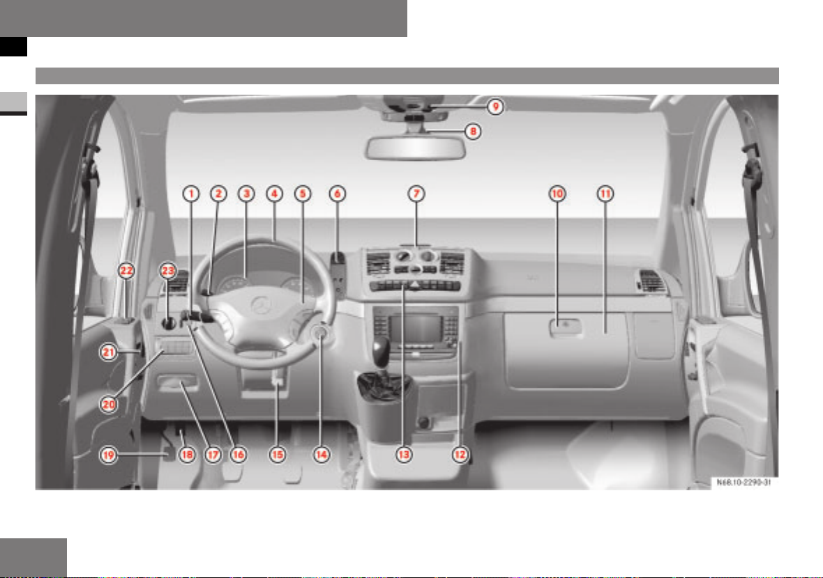
Cockpit
Function Page
1 Combination switch
• Turn signal 140
• Windscreen wipers 144
• Main-beam headlamps 140
2 Cruise control lever
• Cruise control 191
• Speedtronic 188
3 Instrument cluster 22, 26
4 • Steering wheel 97
• Steering wheel with buttons
5 Horn
6 Mobile phone fittings 209
29
Function Page
7 Warning display for Park-
tronic system
8 Rain/light sensor
9 Overhead control panel 32
a Opens the glove compart-
ment
b Glove compartment 203
c Centre console (COMAND,
Audio system or tachograph, see the separate
Operating Instructions)
d Switch unit with hazard
warning lamps switch
e Ignition lock 67
194
203
30
31
Function Page
f Adjusts the steering wheel 97
g Cleans the headlamps 146
h Releases the parking
brake
j Opens the bonnet 249
k Parking brake 178
l Auxiliary heating 166
m Adjusts the seat electri-
cally
n Door control panel 33
o Light switch 138
178
81
1
Nur fuer internen Gebrauch
21
Page 24
At a glance
Instrument cluster versions
Instrument cluster versions
1
Version A
22
Nur fuer internen Gebrauch
Page 25

At a glance
Instrument cluster versions
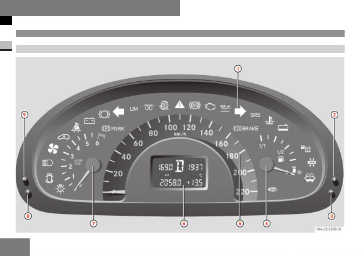
Function Page
1 Indicator and warning
lamps
2 , Button
• Instrument lighting
brighter
• Setting the time 119
• Display settings (for ve-
hicles without steering
wheel buttons)
3 . Button
• Instrument lighting dimmer
• Display settings (for vehicles without steering
wheel buttons)
4 Fuel gauge with reserve
fuel warning lamp
5 Speedometer 101
6 Display 118,
7 Rev counter 101
8 Reset button 4 99
23
101
119
101
119
278
120
Function Page
9 5 Button 99
Indicator and warning
lamps
. Bulb defective 281
9 Door open 64
A Main-beam headlamps 140
R Fan for electronics box de-
fective
ú Electronic level control
(ENR)
< Fasten seat belt 37,
# Battery not being charged 275
2 Brake pads/linings worn 276
7 Parking brake applied 178
& Turn signal, left 140
m Speed limiter 188
q Preglow indicator lamp 173,
281
198
281
278
Function Page
k ASR or AAS malfunction 272
BAS malfunction 272
®
v ESP
- ABS malfunction 273
± Engine diagnostic indica-
N Engine oil level too low 276
/ Turn signal, right 140
6 Brake fluid level too low 271
1 Restraint systems mal-
D Coolant temperature too
/ Coolant level too low 277
M Water in fuel filter 280
A Reserve fuel warning lamp 278
warning lamp 184,
270
ASR warning lamp 183,
270
279
tor lamp
EBV malfunction 270
39,
function
high
275
277
1
ee
Nur fuer internen Gebrauch
23
Page 26

At a glance
Instrument cluster versions
Function Page
1
È Air filter dirty 279
J Washer fluid level too low 280,
i Vehicles with steering wheel buttons:
Corresponding messages may also be shown in
display
6 (e page 284).
296
24
Nur fuer internen Gebrauch
Page 27

At a glance
Instrument cluster versions
1
Nur fuer internen Gebrauch
25
Page 28
At a glance
Instrument cluster versions
Version B
1
26
Nur fuer internen Gebrauch
Page 29

At a glance
Instrument cluster versions
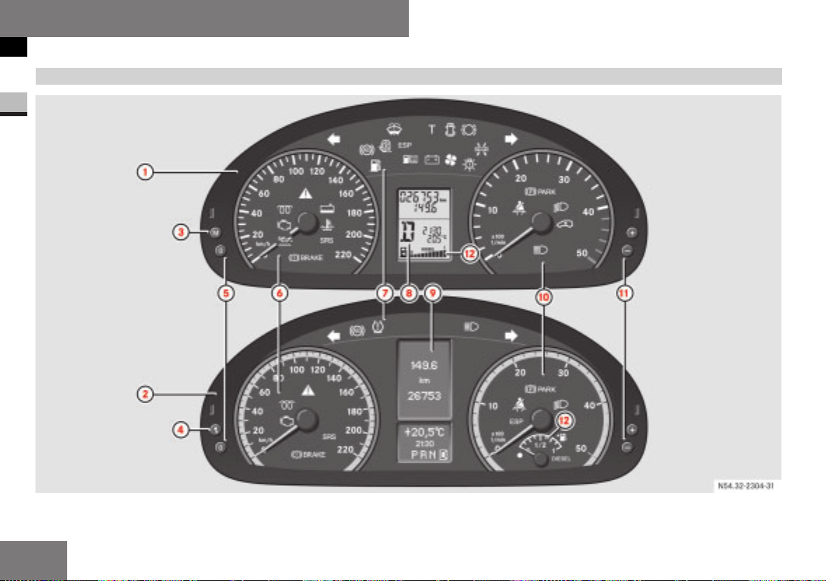
Function Page
1 Instrument cluster in ve-
hicles without steering
wheel buttons
2 Instrument cluster in ve-
hicles with steering wheel
buttons
3 5 In vehicles without
steering wheel buttons:
• Changes the standard
display
• Selects menu 119
4 > In vehicles with
steering wheel buttons:
Checks the engine oil level 254
5 Reset button 0 99
6 Speedometer with: 101
Indicator and warning
lamps
7 Indicator and warning
lamps
8 Display on vehicles with-
out steering wheel buttons
99
99
27
119
Function Page
9 Display on vehicles with
steering wheel buttons
a Rev counter with 101
Indicator and warning
lamps
b ,, . Instrument cluster
illumination brighter/dimmer
c Fuel gauge with: 101
• Reserve fuel warning
lamp
• Location indicator for
fuel filler flap
filler cap is on the left
Indicator and warning
lamps
®
v ESP
/ Coolant level too low 277
D Coolant temperature too
warning lamp 184,
ASR warning lamp 183,
high
Ö: fuel
120
101
278
270
270
277
Function Page
1 Restraint systems mal-
function
6 Brake fluid level too low 271
EBV malfunction 271
N Engine oil level warning 276
± Engine diagnostic indica-
tor lamp
q Preglow system 173,
& Turn signal, left 140
X Tyre pressure warning
lamp
J Windscreen washer/
headlamp cleaning system
washer fluid level too low
9 Door open 281
2 Brake pads/linings worn 276
/ Turn signal, right 140
- ABS malfunction 273
k ASR or AAS malfunction 272
BAS malfunction 272
275
279
278
280
280
1
ee
Nur fuer internen Gebrauch
27
Page 30

At a glance
Instrument cluster versions
Function Page
1
# ESP®malfunction 270
; Air filter dirty 279
A Reserve fuel 278
/ Water in the fuel 280
i Vehicles without steering wheel buttons:
there is a digital fuel gauge in display
Vehicles with steering wheel buttons: there is
an analogue fuel gauge in the rev counter.
i Vehicles with steering wheel buttons:
Corresponding messages may also be shown in
display
6 (
e page 283).
8.
Function Page
# Battery charge malfunc-
tion
R Fan for electronics box de-
fective
. Bulb defective 281
275
281
Function Page
7 Parking brake applied 178
B Dipped-beam headlamps
on
A Main-beam headlamps on 140
< Fasten seat belt 281
138
28
Nur fuer internen Gebrauch
Page 31

At a glance
Steering wheel with buttons
Steering wheel with buttons
Function Page
1 Display 120
Controls on-board computer
2 Selecting a submenu or
adjusting the volume
æ Up / increases the
volume
- Down / decreases
the volume
3 Using the telephone 135
í Accepts a call /
starts dialling
ì Ends a call / rejects
an incoming call
120
Function Page
4 Jumping from one menu to
another
è Forwards
ÿ Back
5 Jumping from one subme-
nu to another
j Forwards
k Back
120
120
1
Nur fuer internen Gebrauch
29
Page 32

At a glance
Centre console
Centre console
1
Function Page
1 Stowage compartment 201
2 • Heating control panel 147
• Air-conditioning control
panel
• Automatic climate control panel
3 COMAND, Audio system
or tachograph, see the
separate Operating Instructions
4 Stowage compartment 201
5 Ashtray with cup holder 200,
6 Cigarette lighter 200
7 Centre console switch unit 31
152
159
205
30
Nur fuer internen Gebrauch
Page 33

At a glance
Switch units
Switch units
Centre console
Function Page
1 Electric sliding door, left-
hand side
2 Switches the rear window
heater on/off
3 Activates/deactivates
ASR
4 Switches the hazard warn-
ing lamps on / off
5 Central locking of entire
vehicle/rear doors
6 Switches the Parktronic
system on/off
7 Electric sliding door, right-
hand side
68
146
183
140
63
194
68
Function Page
8 Switches the right-hand
seat heater on/off
9 Rear interior lighting 143
a PASSENGER AIRBAG OFF
warning lamp
b Switches the rear window
wiper on/off
c Switches the left-hand
seat heater on/off
96
51
145
96
1
Nur fuer internen Gebrauch
31
Page 34

At a glance
Switch units
Roof
1
Function Page
1 Hands-free microphone
for telephone
2 X Switches the right-
hand reading lamp on/off
3 T Sliding/tilting sun-
roof
4 S Switches automatic
interior lighting on/off
209
141
141
Function Page
5 Spectacles compartment 204
Not available with the antitheft alarm system (ATA)
6 W Interior lighting, per-
manently on
7 U Front/rear sliding
sunroof selector switch
8 X Switches the left-
hand reading lamp on/off
79
142
77
141
32
Nur fuer internen Gebrauch
Page 35

At a glance
Switch units
Driver’s door
Function Page
1 Door control panel
• Adjusts the exterior mirrors
• Opens/closes the sliding sunroof
• Opens/closes the
hinged window
• Override switches for
hinged window in the rear
compartment and for the
sliding/tilting sunroof
2 Opens the door 67
3 Adjusts the driver's seat 81
4 Memory function 83
98
74
76
54
1
Nur fuer internen Gebrauch
33
Page 36

34
Nur fuer internen Gebrauch
Page 37

Safety
Occupant safety . . . . . . . . . . . . . . 36
General safety notes . . . . . . . . . . . 55
Tyres and wheels . . . . . . . . . . . . . 56
2
Nur fuer internen Gebrauch
35
Page 38

Safety
Occupant safety
Occupant safety
Restraint systems
This section will familiarise you with the
2
most important features of the restraint
systems in your vehicle. In the event of an
accident, your vehicle may collide with another object, e.g. another vehicle. This
may cause your vehicle to accelerate or
decelerate suddenly. During this acceleration or deceleration, the vehicle occupants
are always thrown towards the force of
the impact. This means that there is a risk
of vehicle occupants being injured on the
vehicle interior or on parts of the vehicle.
The purpose of supplementary restraint
systems, i.e. principally the seat belts supplemented by belt tensioners, belt force
limiters and airbags where necessary, is to
minimise this risk of injury. However, seat
belts and airbags are generally unable to
prevent injuries caused by objects penetrating the vehicle from the outside.
The most important restraint systems are:
I
Seat belts
I
Restraint systems for children, as they
are the most effective means to restrict
occupant movement in the event of an
accident
Additional protection is provided by:
I
The SRS (Supplemental Restraint System) consisting of:
I
1 warning lamp
I
Belt tensioners
I
Belt force limiters
I
Airbag system
i An airbag increases the degree of protec-
tion afforded to a vehicle occupant who is
wearing a seat belt and is therefore supplemental to the seat belt. All vehicle occupants must
wear their seat belt correctly at all times, even
if the vehicle is equipped with airbags. This is
because – on the one hand – airbags are not
deployed in all types of accident, as in some
situations airbag deployment would not increase the protection afforded to vehicle occupants, provided they are wearing their seat belt
correctly.
On the other hand, airbag deployment only provides increased protection if the seat belt is
worn correctly, because:
I
the seat belt helps to keep the vehicle occupant in the best position in relation to the
airbag
I
for example, in a head-on collision, the seat
belt can more adequately prevent the occupant from being propelled towards the force
of the impact, and is thus better suited to
prevent injury
Thus, in accident situations where an airbag is
deployed, it only provides protection in addition
to the seat belt if the seat belt is being worn
correctly.
Risk of injury
G
Modifications to or work performed incorrectly on restraint systems (seat belts, anchorages, belt tensioners, belt force limiters
or airbags) or their wiring, as well as work
on other networked electronic systems,
may prevent the restraint systems from
working correctly. Airbags and belt tensioners could fail, e.g. in the event of an accident, the deceleration force of which
would normally be sufficient to trigger the
systems, or could be triggered unintentionally. Never carry out any modifications on
the restraint systems. Never tamper with
electronic components and their software.
36
Nur fuer internen Gebrauch
Page 39

Seat belts
Risk of injury
G
Airbags provide additional protection; however they are not a replacement for the seat
belts. To reduce the risk of serious or fatal
injuries, make sure that all occupants ‑ in
particular, pregnant women ‑ wear their seat
belt correctly at all times, have adopted a
normal sitting position, and that their seat is
positioned as close to the vertical as possible.
The most important restraint systems are
the seat belts and restraint systems for
children in the vehicle. In the event of an
accident, they are the most effective
means of preventing vehicle occupants
from moving in the direction of the impact
and thus reducing the danger of them hitting parts of the vehicle interior.
i In many countries there are laws concern-
ing the use of seat belts and child restraint systems.
Risk of injury
G
A seat belt which is not worn, which is worn
incorrectly, or which has not been engaged
in the seat belt buckle correctly, cannot perform its intended protective function. Under
certain circumstances this could even cause
severe or fatal injuries. Make sure that all
vehicle occupants ‑ in particular, pregnant
women ‑ wear their seat belt correctly at all
times.
You must make sure that the belt:
I
is routed as low as possible across your
pelvic area, i.e. across your hip joints
and not across your abdomen
I
fits closely
I
is not twisted
I
is routed across the middle of your
shoulder
I
is not routed across your neck or under
your arm
I
fits closely across your pelvic area, by
pulling upwards on the shoulder section
of the belt
Do not secure any objects with a seat belt if
the seat belt is being used by one of the vehicle's occupants.
Avoid wearing bulky clothing, e.g. a winter
coat.
Do not route the belt strap across sharpedged or fragile objects, especially if these
are on or in your clothing, e.g. spectacles,
pencils, keys, etc. The seat belt strap could
be damaged and you could be injured.
Safety
Occupant safety
Only one person should use each seat belt
at any one time.
On no account should children travel sitting
on the lap of another occupant. It would not
be possible to restrain the child, and the
child or other vehicle occupants could be injured seriously in the event of abrupt braking or even fatally in the event of an accident.
Persons under 1.50 m tall or under twelve
years of age cannot wear the seat belts
properly. They therefore require additional
suitable restraint systems on appropriate
seats for protection in an accident. Always
follow the manufacturer's installation instructions when fitting a child seat.
Risk of injury
G
A seat belt only offers its intended degree
of protection if the backrest is positioned as
close to the vertical as possible and the occupant is sitting upright. Avoid seat positions that prevent the seat belt from being
correctly routed . You should therefore position the backrest as close to the vertical as
possible. Never drive with the backrest
tilted too far back. You could otherwise be
seriously or fatally injured in the event of an
accident or sudden braking.
2
ee
Nur fuer internen Gebrauch
37
Page 40

Safety
Occupant safety
Risk of injury
G
The seat belt cannot function correctly if the
belt or buckle is dirty or damaged. Keep the
belt and buckle clean, otherwise the belt
2
tongue cannot engage correctly.
Regularly check the seat belts to make sure
that they:
I
are not damaged
I
are not routed over sharp edges
I
are not trapped
Otherwise the belt could tear in the event of
an accident. You or others could be seriously or fatally injured.
Have seat belts which have been damaged
or subjected to heavy loads in an accident
replaced and have their anchorages
checked.
Mercedes-Benz recommends that, for safety
reasons, you only use seat belts which have
been specially approved for your vehicle by
Mercedes-Benz.
Wearing seat belts
1 Belt sash guide
2 Belt tongue
3 Release button
4 Buckle
E To fasten the seat belt: pull the belt
smoothly out of the belt reel.
E Route the belt across your shoulder.
E Click belt tongue 2 into seat belt
buckle
4.
E If necessary, pull upwards on the shoul-
der section of the belt to tighten it
across your body.
E Adjust the belt to the appropriate
height as necessary.
E To release the seat belt: press re-
lease button
3 on seat belt buckle 4.
Belt height adjustment
Risk of accident
G
Only adjust the seat belt height when the
vehicle is stationary and the pedal-operated
parking brake is applied.
You could otherwise lose control of the vehicle as a result of seat adjusting movements and thereby endanger yourself and
others.
Adjust the belt to a height that allows it to
be routed across the middle of your shoulder.
38
Nur fuer internen Gebrauch
Page 41

5 Release button
E To raise: slide belt sash guide 1 up-
wards.
Belt sash guide
1 engages in various
positions.
E To lower: keep release button 5
pressed.
E Adjust belt sash guide 1 to the appro-
priate height.
E Let go of release button 5 and make
sure that belt sash guide
1 has en-
gaged.
Supplemental Restraint System
(SRS)
The SRS (Supplemental Restraint System)
consists of:
I
1 warning lamp
I
Belt tensioners
I
Belt force limiters
I
Airbag system with:
I
Airbag control unit
I
Airbags
1 warning lamp
The SRS regularly performs a self-check
when the ignition is switched on and while
the engine is running. This allows faults to
be detected in good time.
The
1 warning lamp in the instrument
panel lights up when you switch on the
ignition and goes out a few seconds after
the engine is started.
Risk of injury
G
A malfunction has occurred if the 1
warning lamp:
Safety
Occupant safety
I
does not light up when you switch on
the ignition
I
does not go out after the engine has
been running for a few seconds
I
lights up again
Individual systems could be triggered inadvertently or could fail in the event of an accident with a high rate of vehicle deceleration.
If any of the above occurs, have the SRS
checked and repaired immediately at a
qualified specialist workshop which has the
necessary specialist knowledge and tools to
carry out the work required. Mercedes-Benz
recommends that you use a Mercedes-Benz
Service Centre for this purpose. In particular, work relevant to safety or on safety-related systems must be carried out at a qualified specialist workshop.
Triggering of belt tensioners, belt force
limiters and airbags
In the event of a collision, the sensor in
the airbag control unit evaluates important
physical data, such as the duration, direction and rate of vehicle deceleration or acceleration. Based on the evaluation of this
data and depending on the vehicle’s rate
of longitudinal deceleration in a collision,
2
ee
Nur fuer internen Gebrauch
39
Page 42

Safety
Occupant safety
the belt tensioners are the first to be triggered by the airbag control unit.
The front airbags are not deployed unless
a second activation threshold is reached,
i.e. there is a higher rate of vehicle decel-
2
eration in a longitudinal direction.
! The seat belt for the middle seat is only fit-
ted with a belt tensioner on vehicles with a codriver's double airbag.
Criteria for triggering belt tensioners
and airbags
In the first stages of a collision, the sensor
in the airbag control unit evaluates physical data, such as duration, direction and
rate of vehicle deceleration or acceleration
in order to determine whether it is necessary to trigger the belt tensioners and/or
deploy the airbags.
The triggering thresholds for the belt tensioners and airbags are variable and are
adapted to the rate of vehicle deceleration. This process is pre-emptive in nature
since the airbag must be deployed during,
and not at the end of, the collision.
i Airbags are not deployed in all types of ac-
cident. They are controlled by a complex sensor system and evaluation logic. This process is
pre-emptive in nature as airbag deployment
must take place during the impact and must be
adapted to provide calculated, additional protection for the vehicle occupants. Not all airbags are deployed in an accident.
The various airbag systems work independently
of each other. However, the deployment of
each individual system depends on the type of
impact (head-on or side impact) and the severity of the impact (in particular, the vehicle's
rate of deceleration or acceleration) as determined by the control system in the initial
stages of the accident.
Vehicle deceleration or acceleration and
the direction of the force are essentially
determined by:
I
the distribution of the force during the
impact
I
the collision angle
I
the deformation characteristics of the
vehicle
I
the characteristics of the object with
which the vehicle has collided, e.g. the
other vehicle
Factors which can only be seen and measured after the collision has occurred, do
not determine whether the airbags are deployed and do not provide an indication of
their deployment.
The vehicle may be considerably deformed
without an airbag being deployed if, for example, only relatively easily deformable
parts, such as the bonnet or wings, have
been hit and the required rate of deceleration has not been reached. It is also possible that airbags may be deployed even
though the vehicle is only slightly deformed, if, for example, very rigid vehicle
parts such as the longitudinal members
are hit in an accident and the rate of deceleration is sufficient.
Belt tensioners, belt force limiters
The front seat belts have belt tensioners.
Belt tensioners tighten the seat belts in an
accident, pulling them close against the
seat occupant's body.
i Belt tensioners do not correct:
I
incorrect sitting positions
I
incorrectly worn seat belts
Belt tensioners do not pull occupants back towards the backrest.
If the seat belt is also equipped with a belt
force limiter, the force exerted by the seat
belt on the seat occupant is reduced.
40
Nur fuer internen Gebrauch
Page 43

The belt force limiter is fine-tuned to the
front airbag, which takes over a part of the
restraining forces, thus spreading the
forces exerted on the occupant over a
greater area.
When the ignition is switched on, the belt
tensioner is activated:
I
only when the restraint systems are operational (the
1 warning lamp lights
up after the ignition is switched on and
goes out once the engine is running)
(
e page 39)
I
in the event of a head-on or rear-end
collision if the vehicle decelerates or
accelerates rapidly in a longitudinal direction during the initial stages of the
collision
If the belt tensioners are triggered, you will
hear a bang, which will not cause any
harm to your hearing, and a small amount
of powder may also be released. The
1
warning lamp lights up.
Risk of injury
G
Have belt tensioners which have been triggered replaced at a qualified specialist
workshop which has the necessary specialist knowledge and tools to carry out the
work required. Mercedes-Benz recommends
that you use a Mercedes-Benz Service
Centre for this purpose. In particular, work
relevant to safety or on safety-related systems must be carried out at a qualified specialist workshop
Comply with safety regulations when disposing of belt tensioners. Any MercedesBenz Service Centre can provide details of
these regulations.
Airbag system
Risk of injury
G
To reduce the risk of serious or fatal injuries
in the event of an accident or similar situation with a high rate of deceleration, e.g. injuries caused by an airbag inflating within
milliseconds or sudden braking, please observe the following points:
I
All vehicle occupants must select a seat
position that allows the seat belt to be
worn correctly and that is as far away
from the airbag as possible. The seat position of the driver must still allow him
to control the vehicle safely. The driver
must maintain a distance from the pedals such that he can depress them fully.
The distance between the driver’s chest
and the centre of the airbag cover must
Occupant safety
be more than 25 cm. The driver’s arms
should be slightly bent when holding the
steering wheel.
I
Vehicle occupants should always wear
their seat belt correctly and position
their backrest as close to the vertical as
possible. The head restraints should
support the back of the head at about
eye level.
I
Move the co-driver's seat as far back as
possible, especially if a child is secured
in a restraint system on this seat.
I
Rearward-facing child restraint systems
must not be fitted to the co-driver's seat
unless the co-driver's front airbag has
been deactivated. In Mercedes-Benz vehicles, the co-driver's front airbag is deactivated if a child restraint system with
automatic child seat recognition is fitted
to the co-driver's seat of a vehicle with
automatic child seat recognition on the
co-driver's seat and the PASSENGER
AIRBAG OFF warning lamp remains lit
continuously.
If the rearward-facing child restraint system does not have automatic child seat
recognition, or if your vehicle does not
have automatic child seat recognition on
the co-driver's seat, children must be secured in a child restraint system on a
Safety
2
ee
Nur fuer internen Gebrauch
41
Page 44

Safety
Occupant safety
suitable seat in the rear. If you secure a
forward-facing child restraint system to
the co-driver's seat, you must move the
co-driver's seat as far back as possible.
I
2
Do not lean forwards, e.g. over the padded boss of the steering wheel, particularly when the vehicle is in motion.
I
Do not put your feet on the dashboard.
I
Only hold the steering wheel by the rim.
This allows the airbag to inflate fully. If
you hold on to the inside of the steering
wheel, you could be injured if the airbag
is deployed.
I
Do not lean on the doors from inside the
vehicle.
I
Make sure that there are no people, animals or objects between the vehicle occupants and the area of deployment of
the airbags.
I
Do not place any objects between the
seat backrest and the door.
I
Do not hang any hard objects, e.g. coat
hangers, on the grab handles or coat
hooks.
Due to the high speed at which airbags have
to deploy, the risk of injuries caused by airbag deployment cannot be completely ruled
out.
Risk of injury
G
The airbag function is only guaranteed if
you:
I
do not cover or affix badges or stickers
to the padded boss of the steering
wheel, the co-driver's front airbag cover,
the thorax/side-impact airbag cover on
the side cushions of the front seats and
the windowbag covers in the roof frame
I
do not modify the restraint system components, including the wiring
Your vehicle is equipped with the following
airbags, depending on the equipment version:
I
Driver’s front airbag, located in the
steering wheel
I
Co-driver’s front airbag located above
the glove compartment
I
Thorax/side-impact airbags in the side
cushions on the outer side of the front
seats (individual seats only)
I
Windowbags in the side roof frame between the A-pillar and B-pillar
Airbag deployment
An airbag inflates within milliseconds. The
1 warning lamp lights up.
i If the airbag is deployed, you will hear a
bang and a small amount of powder may also
be released. The bang will not damage your
hearing and the powder does not constitute a
health hazard.
An inflated airbag slows and reduces the
movement of the vehicle occupants.
When the vehicle occupant makes contact
with the airbag, hot gas flows out of the inflated airbag. This feature is designed to
reduce the force acting on the occupant’s
head and chest. The airbag is therefore in
a deflated state after an accident.
Risk of injury
G
After an airbag has been deployed:
I
airbag parts are hot. Do not touch them,
or you could be burned
I
it must be replaced at a qualified specialist workshop which has the necessary specialist knowledge and tools to
carry out the work required. MercedesBenz recommends that you use a
Mercedes-Benz Service Centre for this
purpose. In particular, work relevant to
safety or on safety-related systems must
be carried out at a qualified specialist
workshop
42
Nur fuer internen Gebrauch
Page 45

Risk of injury
G
A small amount of powder is released when
an airbag is deployed. This powder is not
hazardous to health and does not indicate
that there is a fire in the vehicle. The powder could cause short-term breathing difficulties in people with asthma or breathing
problems. To prevent these breathing difficulties, you should either:
I
leave the vehicle immediately, if it is safe
to do so
or
I
open a window to allow fresh air to enter
Front airbags
The front airbags are designed to increase
the degree of protection afforded to the
driver and co-driver against head and
chest injuries. The driver's front airbag
and co-driver's front airbag are deployed:
I
in the initial stages of an accident with
a high rate of vehicle acceleration or
deceleration in a longitudinal direction
I
if the system determines that airbag
deployment can offer additional protection to that provided by the seat belt
I
if the seat belt is fastened
I
independently of other airbags in the
vehicle
I
if the vehicle overturns, never, unless
the system detects high vehicle deceleration in a longitudinal direction
The driver’s front airbag is located in the
steering wheel; the co-driver’s front airbag
is located above the glove compartment.
12
N91.60-2036-31
1 Driver’s front airbag
2 Co-driver’s front airbag
Driver's front airbag
1 deploys in front of
the steering wheel; co-driver's front airbag
2 deploys in front of and above the glove
compartment.
i Vehicles with automatic child seat recogni-
tion in the co-driver's seat:
Safety
Occupant safety
Co-driver's front airbag
the PASSENGER AIRBAG OFF warning lamp below the hazard warning lamp switch is not lit
(
e page 30). This means that a child restraint
system with automatic child seat recognition
has not been fitted to the co-driver's seat or
has been fitted incorrectly.
Thorax/side-impact airbags
Risk of injury
G
For safety reasons, Mercedes-Benz recommends that you use seat covers that have
been tested for Mercedes-Benz vehicles and
which have a special recess for thorax/sideimpact airbags. A thorax/side-impact airbag
may otherwise not inflate correctly and may
fail to provide the intended degree of protection in the event of a collision. You can
obtain these covers from a Mercedes-Benz
Service Centre, for example.
Risk of injury
G
To reduce the risk of injury when a thorax/
side-impact airbag is deployed, you should
make sure that:
I
no persons, animals or objects are
present between the vehicle occupants
2 is only activated if
2
ee
Nur fuer internen Gebrauch
43
Page 46

Safety
Occupant safety
and the thorax/side-impact airbag’s deployment range
I
no accessories, e.g. drinks can holders,
are attached to the doors
I
2
only light clothing is hung on the coat
hooks in the vehicle
I
there are no heavy or sharp objects in
the pockets of items of clothing
Risk of injury
G
To reduce the risk of severe or fatal injury
when the thorax/side-impact airbag is deployed, you must ensure that:
I
vehicle occupants – in particular, children – never lean their head in the area
of the window where the thorax/sideimpact airbag inflates.
I
vehicle occupants wear their seat belt
correctly at all times and lean back
against the backrest, which should be
positioned as close to the vertical as
possible.
I
children less than 1.50 m tall or under
12 years of age are secured in suitable
child restraint systems.
The purpose of thorax/side-impact airbag
deployment is to enhance the level of protection for the thorax (but not the head,
neck or arms) of the vehicle occupants on
the side of the vehicle on which the impact
occurs.
The thorax/side-impact airbags are integrated into the outer side of the backrests
on the front seats (individual seats only).
1 Thorax/side-impact airbag
The thorax/side-impact airbags inflate between the door and occupants in the area
of the thorax.
The thorax/side-impact airbags are deployed:
I
at the start of an accident with a high
rate of lateral vehicle deceleration or
acceleration, e.g. in a side impact
I
on the side on which the impact occurs
I
whether or not the seat belt is fastened
I
independently of the front airbags
I
independently of the belt tensioner
i Vehicles with automatic child seat recogni-
tion in the co-driver's seat:
The co-driver's thorax/side-impact airbag is activated even if the PASSENGER AIRBAG OFF
warning lamp below the hazard warning lamp
switch is lit (
straint system with automatic child seat recognition is fitted on the co-driver's seat.
e page 30), i.e. even if a child re-
i You will find additional information about
airbag deployment on (
You can find further information about the triggering of belt tensioners and belt force limiters
on (
e page 39).
Windowbags
Risk of injury
G
In order for the windowbag to provide its intended level of protection, make sure that
there are no objects between the vehicle occupants and the area of deployment of the
windowbags.
Risk of injury
G
Observe the following notes to reduce the
risk of serious or fatal injury if the windowbag is deployed:
e page 42).
44
Nur fuer internen Gebrauch
Page 47

I
Vehicle occupants ‑ in particular, children ‑ must not lean their head on the
area of the window in which the windowbag is deployed
I
Vehicle occupants must always have
their seat belts fastened correctly
I
Always secure children less than 1.50 m
tall or under 12 years of age in suitable
child restraint systems
The purpose of windowbag deployment is
to enhance protection for the head (but
not the chest or arms) of the vehicle occupants on the side of the vehicle on which
the impact occurs.
The windowbags are integrated into the
side of the roof frame and run from in front
of the front door (A-pillar) to behind the
front door (B-pillar).
1 Windowbag
The windowbags are deployed:
I
in the initial stages of an accident with
a high rate of vehicle acceleration or
deceleration in a lateral direction
I
on the side on which the impact occurs
I
regardless of whether the co-driver's
seat is occupied
I
whether or not the seat belt is fastened
I
independently of the front airbags
I
independently of the belt tensioner
Safety
Occupant safety
i You will find additional information about
airbag deployment on (
You can find further information about the triggering of belt tensioners and belt force limiters
on (
e page 39).
Children in the vehicle
If a child is travelling in the vehicle:
I
secure the child, preferably on a suitable rear seat, using a child restraint
system appropriate to his/her age and
size and which has been approved for
Mercedes-Benz vehicles
I
ensure that the child is strapped in
throughout the trip
I
activate the child-proof locks for the
vehicle doors and for the hinged window and the sliding sunroof in the rear
You can obtain child seats and information
about the correct child restraint system
from any Mercedes-Benz Service Centre.
Risk of injury
G
Do not leave children unsupervised in the
vehicle, even if they are secured in a child
restraint system. The children could:
e page 42).
2
ee
Nur fuer internen Gebrauch
45
Page 48

Safety
Occupant safety
I
injure themselves on parts of the vehicle
I
be severely or even fatally harmed by
prolonged exposure to intense heat or
cold
Do not expose the child restraint system to
2
direct sunlight, as this could cause, for example, metallic parts of the child restraint
system to become very hot. Touching these
parts could cause skin burns.
If the children open a door, they could:
I
injure other people in doing so
I
get out of the vehicle and thereby injure
themselves or be injured by a passing
vehicle
Do not carry heavy or hard objects inside
the vehicle unless they are secured. You will
find further information under “Loading
guidelines” in the index.
An unsecured or incorrectly positioned load
increases the risk of injury to the child in
the event of:
I
sharp braking
I
a sudden change in direction
I
an accident
Child restraint systems
Mercedes-Benz recommends that you only
use child restraint systems suitable for the
age and size of the children on the different seats. (
G
To reduce the risk of serious or fatal injury
to the child in the event of an accident,
braking or sudden change in direction:
I
I
I
e page 49)
Risk of injury
Always secure children less than 1.50 m
tall and under 12 years of age in a special child restraint system installed on a
suitable vehicle seat, as the seat belts
are not designed for passengers of this
size.
Do not allow children under 12 years of
age to sit on the co-driver's seat unless
they are secured in a child restraint system with automatic child seat recognition in vehicles which also have automatic child seat recognition on the codriver's seat.
On no account should children travel sitting on the lap of another occupant. The
forces produced in the event of an accident, sharp braking or a sudden change
in direction make it impossible for a
child to be held securely. He/she may
be thrown against parts of the vehicle interior and be seriously or fatally injured.
I
All vehicle occupants must always have
their seat belt fastened correctly.
I
If you fit a child restraint system to the
co-driver's seat, you must move the codriver's seat as far back as possible.
Risk of injury
G
If the child restraint system is not fitted correctly to a suitable seat, the child may no
longer be secured in the event of an accident or sudden braking and may be seriously or fatally injured. When fitting a child restraint system, you must observe the manufacturer's installation instructions and correct use of the child restraint system.
Child restraint systems should preferably be
fitted to the rear seats. The child is generally
better protected there.
Never place objects, e.g. cushions, under
the child restraint system. The entire base
of the child restraint system must always be
resting on the seat cushion.
Child restraint systems must not be used
without their original cover. Only replace
damaged covers with genuine MercedesBenz covers.
Only use child restraint systems which have
been recommended for Mercedes-Benz on
the rear seats.
46
Nur fuer internen Gebrauch
Page 49

Risk of injury
G
If you no longer require the child restraint
system, remove it from the vehicle or secure
it with the seat belt.
The restraint system could otherwise be
thrown through the vehicle interior in the
event of an accident.
Risk of injury
G
If the child restraint system or its securing
system has already been damaged or subjected to a load in an accident, a child subsequently secured in it could be seriously or
fatally injured in the event of an accident,
braking or a sudden change in direction.
Have restraint systems and their securing
systems which have been damaged or subjected to a load in an accident checked and,
if necessary, replaced immediately at a
qualified specialist workshop which has the
necessary specialist knowledge and tools
for the work required.
Mercedes-Benz recommends that you use a
Mercedes-Benz Service Centre for this purpose. All work relevant to safety or on
safety-related systems must be carried out
at a qualified specialist workshop.
Safety
Occupant safety
2
Nur fuer internen Gebrauch
47
Page 50

Safety
Occupant safety
Suitable vehicle seats
Weight and age categories Child restraint system on the
co-driver's seat
Category 0: up to 10 kg
2
up to approximately 9 months
Category 0+: up to 13 kg
As recommended
as recommended
1
1
Child restraint system on
the individual seat (rear)
Universal
Universal
2
2
Child restraint system on the
rear bench seat
Universal
Universal
2
2
up to approximately 18 months
Category I: 9to18kg
Universal
3
Universal Universal
between approximately 8 months
and 4 years
Category II/III: 15 to 36 kg
Universal
3
Universal Universal
between approximately 3½ and 12
years
1
Only use child restraint systems with automatic child seat recognition.
2
Forward-facing child restraint system in the “Universal” category.
3
If you are using a child restraint system without automatic child seat recognition, move the co-driver's seat to its rearmost position. The automatic child seat recognition is only available with comfort and deluxe seats (individual seat).
48
Nur fuer internen Gebrauch
Page 51

Safety
Occupant safety
“Universal” category child restraint systems can be recognised by their orange
approval label. The label is affixed to the
child seat and identifies the type of child
seat.
Example of an approval label on the child
restraint system
Recommended child restraint systems
Weight and age categories Manufacturer Model Type approval number DaimlerChrysler order
number
Category 0: up to 10 kg
up to approximately 9 months
Category 0+: up to 13 kg
up to approximately
18 months
Britax Römer BABY SAFE PLUS E1 03 301146 B6 6 86 8212
B6 686 8213
Britax Römer BABY SAFE PLUS E1 03 301146 B6 6 86 8212
B6 686 8213
2
ee
Nur fuer internen Gebrauch
49
Page 52

Safety
Occupant safety
Weight and age categories Manufacturer Model Type approval number DaimlerChrysler order
number
Category I: 9to18kg
between approximately 8
2
months and 4 years
Category II/III: 15 to 36 kg
between approximately
3½ and 12 years
Britax Römer DUO PLUS E1 03 301133 B6 6 86 8217
B6 6 86 8218
Britax Römer KID E1 03 301148 B6 6 86 8308
B6 6 86 8309
B6 6 86 8302
B6 6 86 8303
Warning sticker on the co-driver's sun visor
50
Risk of injury
G
The co-driver's front airbag is not deactivated:
I
in vehicles without automatic child seat
recognition on the co-driver's seat
I
in vehicles with automatic child seat recognition on the co-driver's seat, if a special child restraint system with automatic child seat recognition has not
been fitted to the co-driver's seat or the
PASSENGER AIRBAG OFF warning lamp
is not lit
If the co-driver's front airbag is not deactivated, a child secured in a child restraint
system on the co-driver's seat could be seri-
ously or fatally injured by the co-driver's
front airbag deploying in the event of an accident, especially if the child is in the immediate vicinity of the co-driver's front airbag
when it is deployed.
To draw attention to this danger, there is an
appropriate warning sticker on the dashboard as well as on either side of the codriver's sun visor.
If the co-driver's front airbag is not deactivated, a child must never be secured on the
co-driver's seat in a rearward-facing child restraint system. Only secure a rearwardfacing child restraint system to a suitable
rear seat.
Nur fuer internen Gebrauch
Page 53

If you secure a child in a forward-facing
child restraint system on the co-driver's
seat and the co-driver's front airbag is not
deactivated (e.g. in vehicles without automatic child seat recognition on the co-driver's or in vehicles with automatic child seat
recognition on the co-driver's seat and if the
PASSENGER AIRBAG OFF warning lamp is
not lit), always position the co-driver's seat
in its rearmost position.
Information about recommended child restraint systems is available at any
Mercedes-Benz Service Centre.
Do not place any objects, e.g. a cushion,
under the child restraint system. The entire
base of the child restraint system must always be resting on the seat cushion. An incorrectly fitted child restraint system cannot
perform its intended protective function in
the event of an accident, and could even
lead to injuries.
N00.00-2620-31
Warning symbol for a rearward-facing child
restraint system
Automatic child seat recognition on
the co-driver's seat
If your vehicle does not have automatic
child seat recognition on the co-driver's
seat, this is indicated by a special sticker.
The sticker is affixed to the side of the
dashboard on the co-driver's side. It is visible when you open the co-driver's door.
(
e page 51)
Safety
Occupant safety
The warning lamp is below the hazard
warning lamp switch on the centre console.
2
1 PASSENGER AIRBAG OFF warning
lamp
The sensor system for the comfort and deluxe co-driver’s seats automatically detects if a special Mercedes-Benz child seat
with automatic child seat recognition is fitted there. If this is the case, the
PASSENGER AIRBAG OFF warning lamp
lights up on the centre console. The codriver's front airbag has been disabled.
Nur fuer internen Gebrauch
Risk of injury
G
If the PASSENGER AIRBAG OFF warning
lamp does not light up when the child restraint system is fitted, the co-driver's front
ee
51
Page 54

Safety
Occupant safety
airbag has not been deactivated. The child
could suffer life-threatening injuries if the
co-driver's front airbag is deployed.
If the PASSENGER AIRBAG OFF warning
lamp does not light up, proceed as follows:
2
I
Do not use a rearward-facing child restraint system on the co-driver's seat.
I
Fit a rearward-facing child restraint system on a suitable rear seat.
or
I
Only use a forward-facing child seat on
the co-driver's seat. When doing so,
move the co-driver’s seat to its rearmost
position.
I
Have the automatic child seat recognition system checked at a qualified specialist workshop which has the necessary specialist knowledge and tools to
carry out the work required. MercedesBenz recommends that you use a
Mercedes-Benz Service Centre for this
purpose. In particular, work relevant to
safety or on safety-related systems must
be carried out at a qualified specialist
workshop.
To ensure that the automatic child seat recognition on the co-driver's seat functions
correctly, never place objects (e.g. a cushion) under the child restraint system. The
entire base of the child restraint system
must always be resting on the seat cushion.
An incorrectly fitted child restraint system
cannot perform its intended protective function in the event of an accident, and could
even lead to injuries.
i The windowbag, the thorax/side-impact
airbag and the belt tensioner on the co-driver’s
side remain enabled even if the co-driver’s front
airbag is disabled.
Risk of injury
G
Do not place items of electronic equipment
on the co-driver's seat, e.g.:
I
laptops, if switched on
I
mobile phones
I
cards with transponders, e.g. ski passes
or access passes
as the signals from electronic equipment
can cause interference in the sensor system
of the automatic child seat recognition system. This can lead to a system malfunction
and cause the PASSENGER AIRBAG OFF
warning lamp:
I
to light up even when there is no child
seat with automatic child seat recognition fitted, meaning that the co-driver's
front airbag will not be deployed in the
event of an accident
I
not to light up briefly when the key is
turned to position 2 in the ignition lock
ISOFIX child seat securing system
ISOFIX is a standardised securing system
for special child seats in the rear. The securing rings for the child restraint systems
are located between the seat cushions
and the backrest.
Risk of injury
G
A child restraint system secured by the ISOFIX child seat securing system does not provide sufficient protection for children weighing more than 22 kg. For this reason, do not
secure children weighing more than 22 kg
in a child restraint system secured by the
ISOFIX child seat securing system. If the
child weighs more than 22 kg, secure the
child restraint system using a lap-shoulder
belt.
52
Nur fuer internen Gebrauch
Page 55

Risk of injury
G
If the child restraint system is not fitted correctly to a suitable vehicle seat, the child
may not be secured in the event of an accident or sudden braking and may be seriously or fatally injured. Follow the manufacturer's installation instructions when fitting the
child restraint system.
On the rear seats, only use child restraint
systems with an ISOFIX child seat securing
system and which have been recommended
for use in Mercedes-Benz vehicles.
An incorrectly fitted child restraint system
could come loose and fatally injure the child
or other vehicle occupants. When fitting the
child restraint system, make sure that it is
engaged in the securing rings on both sides.
Risk of injury
G
If the child restraint system or its securing
system, e.g. ISOFIX child seat securing system, has been damaged or subjected to a
load in an accident, the child secured in it
could be seriously or fatally injured in the
event of an accident, braking or a sudden
change in direction.
Always have child restraint systems and
their securing systems which are damaged
or have been subjected to a heavy load in
an accident checked and, if necessary, replaced immediately at a qualified specialist
workshop which has the necessary specialist knowledge and tools to carry out the
work required. Mercedes-Benz recommends
that you use a Mercedes-Benz Service
Centre for this purpose. In particular, work
relevant to safety or on safety-related systems must be carried out at a qualified specialist workshop.
! When fitting the child restraint system in
vehicles with a rear bench seat, make sure that
the seat belt for the middle seat does not get
trapped.
1 Securing rings (not visible)
E To fit the child seat: move the back-
rest to the rearmost detent position
(comfort seats).
Safety
Occupant safety
E Secure the child seat to the two secur-
ing rings
seat manufacturer's instructions.
E Return the backrest to the foremost
detent position.
E To remove the child seat: see the
child-seat manufacturer's instructions.
G
Do not leave children unsupervised in the
vehicle, even if they are secured in a child
restraint system. The children could:
I
injure themselves on parts of the vehicle
I
be severely or even fatally injured by
prolonged exposure to intense heat or
cold
Do not expose the child restraint system to
direct sunlight, as this could cause, for example, metal parts of the child restraint system to become very hot. Touching these
parts could cause skin burns.
If the children open a door, they could:
I
thereby cause injury to other persons
I
get out of the vehicle and injure themselves or be injured by a passing vehicle
1, as described in the child-
Risk of injury
2
Nur fuer internen Gebrauch
53
Page 56

Safety
Occupant safety
Child-proof locks
If children are travelling in the vehicle, you
can activate the child-proof locks for the
rear.
2
When the child-proof locks for the doors
are activated, you can childproof the sliding doors and the tailgate/rear door individually. If a door has been childproofed:
I
it cannot be opened from the inside
I
it can only be opened from the outside
if the vehicle is unlocked
Risk of injury
G
Activate the child-proof locks on the rear
doors and deactivate the hinged window
and sliding sunroof controls in the rear compartment when children are travelling in the
vehicle. The children could otherwise open
the doors, hinged windows or sliding sunroof in the rear while the vehicle is in motion, thereby injuring themselves and
others.
Child-proof locks on sliding doors
The rotary mechanism for the child-proof
locks is located towards the rear edge of
the sliding doors.
1 Child-proof locks
E To activate: use a suitable object to
turn child-proof lock
1 to the on posi-
tion.
E Check that the child-proof locks are
working properly.
E To deactivate: use a suitable object to
turn child-proof lock
1 to the off posi-
tion.
i When you activate the child-proof lock in
the electric sliding door, the buttons on the Bpillar and on the interior door handle of the
electric sliding door are not operational.
Child-proof locks on the tailgate/rear
door
The latch for the child-proof lock is located
on the lower edge of the tailgate or on the
front edge of the right-hand rear door.
1 Latch for the child-proof lock
E To activate: slide latch 1 to the
right/downwards.
E Check that the child-proof locks are
working properly.
54
Nur fuer internen Gebrauch
Page 57

E To deactivate: slide latch 1 to the
left/upwards.
Child-proof locks for rear electric
hinged windows and the sliding sunroof in the rear
Risk of injury
G
Activate the child-proof locks on the rear
doors and deactivate the hinged window
and sliding sunroof controls in the rear compartment when children are travelling in the
vehicle. The children could otherwise open
the doors, hinged windows or sliding sunroof in the rear while the vehicle is in motion, thereby injuring themselves and
others.
The switch is located in the door control
panel on the driver's door.
1 Switch
E To activate or deactivate: press
switch
1.
1 engages or extends. If the
Switch
switch is engaged, you can no longer
operate the rear hinged windows and
the sliding sunroof in the rear using the
switches in the rear compartment.
i Even if switch 1 is engaged, you can still
open the rear hinged windows using the
switches on the driver's door.
Safety
General safety notes
General safety notes
Stickers
There are various warning stickers affixed
to your vehicle. They serve to make you
and others aware of various dangers.
Risk of injury
G
Do not remove any warning stickers.
If you remove warning stickers, it may prevent you or others from recognising dangers. This could result in injury to yourself
or others.
Substances constituting a health
hazard
Do not store or transport in the cab substances which are hazardous to health and
substances which react aggressively.
These include:
I
solvents
I
fuels
I
oils and grease
I
cleaning agents
I
acids
2
ee
Nur fuer internen Gebrauch
55
Page 58

Safety
Tyres and wheels
Risk of fire and accident
G
Do not store or transport in the cab substances which are hazardous to health and
substances which react aggressively. Gases
2
and fluids can escape even from securely
closed containers. This can:
I
compromise your health and ability to
concentrate on driving the vehicle
I
damage electrical components (e.g. control units and plug connectors), resulting
in malfunctions, system failures and
even short circuits, which could start a
fire
You could cause an accident and injure
yourself and others.
Tyres and wheels
Operating and driving safety
Tyres are particularly important for the operating reliability and driving safety of the
vehicle. You should therefore check the
tyre pressure, tyre tread and tyre condition
on a regular basis.
A specialist tyre store, a qualified specialist workshop or any Mercedes-Benz
Service Centre will be able to give you further information about:
I
List of recommended makes of tyre
I
Tyre load-bearing capacity (LI Load Index)
I
Speed index (maximum permissible
tyre speed)
I
Tyre age
I
Causes and effects of tyre wear
I
Measures to be taken in the event of
tyre damage
I
Tyre types for specific regions, areas of
operation or conditions of vehicle use
I
Possibilities for changing tyres, etc.
Modifications to the brake system or
wheels are not permissible, nor is the use
of spacer plates or brake dust shields. Any
such modifications will invalidate the vehicle's general operating permit.
Risk of accident
G
For safety reasons, Mercedes-Benz recommends that you only use tyres which have
been approved by Mercedes-Benz specifically for your vehicle. These tyres are specially adapted for the vehicle handling characteristics, comfort, wear and for use with
the control systems, such as ABS or ESP
If you use other tyres, Mercedes-Benz cannot accept any responsibility for damage
which may occur. You can obtain information about tyres from any Mercedes-Benz
Service Centre.
If you fit tyres other than those tested and
recommended for Mercedes-Benz, characteristics such as handling, noise levels, fuel
consumption and wear, etc. may be adversely affected. In addition, when driving
with a load, dimensional variations and different tyre deformation characteristics
could cause the tyres to make contact with
the bodywork and axle components. This
could result in damage to the tyres or the
vehicle.
®
.
56
Nur fuer internen Gebrauch
Page 59

Run in new tyres at moderate speeds for
the first 100 km.
Risk of accident
G
Loose wheel nuts or bolts could cause you
to lose a wheel while the vehicle is in motion. You could lose control of the vehicle as
a result, cause an accident and injure yourself or others.
You should therefore tighten the wheel nuts
or wheel bolts regularly, at least once a
year, to the specified tightening torque.
You will find further information on winter
tyres in the “Operation” section
(
e page 235).
You will find information about the tightening torque for wheel bolts in the “Technical
data” section (
e page 354).
Tyre pressures
Risk of accident
G
Always observe the specified tyre pressures
for your vehicle.
The tyre temperature and pressure increase
when the vehicle is in motion. You should
therefore never reduce the pressure of
warm tyres. The pressure would then be too
low once the tyres have cooled.
The tyre pressure must be adjusted to the
load of the vehicle. If the tyre pressure is
too low, it may cause the tyre to burst, especially at higher loads and speeds. A tyre
pressure that is too high can cause a longer
braking distance and a poorer tyre grip.
If the tyre pressure has been incorrectly set,
you could lose control of your vehicle, causing an accident and injuring yourself or
others.
Check the specified tyre pressure regularly
when the tyres are cold. You should do
this at least once every two weeks and before long journeys.
Correct the tyre pressure before loading
the vehicle. Check tyre pressures after
loading the vehicle and correct them as
necessary.
I
If the tyre pressure is too low, it can
cause excessive tyre temperatures, increased tyre wear, altered directional
stability and increased fuel consumption.
I
If the tyre pressure is too high, it can
cause a longer stopping distance, poorer tyre grip and increased tyre wear.
Safety
Tyres and wheels
I
Valve caps on the tyre valves protect
the valve core from moisture and dirt.
You must therefore always screw the
valve caps tightly onto the tyre valves.
I
If there is repeated pressure loss from
the tyres, this may be caused by external damage, foreign objects in the tyre
tread, cracks, bulges or leaking tyre
valves.
You will find the tyre inflation pressure tables in the “Technical data” section
(
e page 352).
Tyre tread
A minimum tyre tread depth is specified
by law. You should therefore observe the
respective legal requirements for the relevant country.
I
The smaller the remaining tread depth,
the poorer the grip and handling of the
vehicle will be, especially on wet or
snow-covered road surfaces.
I
When the tread depth is less than
3 mm, tyre grip is drastically reduced
on wet roads, for example. For safety
reasons, you should have the tyres replaced before they reach the minimum
tread depth specified by law.
2
ee
Nur fuer internen Gebrauch
57
Page 60

Safety
Tyres and wheels
Risk of accident
G
You should always make sure that there is
sufficient tyre tread. If the tyre tread depth
is insufficient, the risk of aquaplaning in
2
heavy rain or slush and at high speeds increases. The tyre tread is no longer able to
route the water away. You could lose control of the vehicle as a result, cause an accident and injure yourself or others.
Tyre condition
you to lose control of the vehicle, causing
an accident and injuring yourself or others.
Have damaged tyres replaced immediately.
Tyre age
Tyres age, even if they are rarely used or
not used at all. Operating and driving
safety diminishes with tyre age. You
should therefore have tyres more than six
years old replaced. This also applies to the
spare wheel.
Damage to the tyre substructure cannot be
detected until later and can cause the tyre
to burst.
You could lose control of the vehicle as a result, cause an accident and injure yourself
or others.
Avoid tyre impact with kerbs or parking with
part of the tyre tread on the kerb.
Tyre load capacity, maximum tyre
speed and types of tyre
Check the tyre condition regularly, at least
once every two weeks and before long
journeys, e.g. for:
I
external damage
I
foreign objects in the tread
I
cracks, bulges
I
tyre tread depth and/or one-sided or
uneven tread wear. Turn the front
wheels inwards to check the inside of
the front wheels better. Always check
the insides of the tread on the rear
tyres too.
Risk of accident
G
Note that cracks, bulges and other damage
can cause a tyre to burst. This could cause
58
Nur fuer internen Gebrauch
Tyre damage
Tyre damage can be caused by:
I
the operating conditions of the vehicle
I
tyre ageing
I
kerbs
I
foreign objects
I
insufficient or excessive tyre pressure
I
weather or environmental conditions
I
contact with oil, grease, fuel, etc.
Risk of accident
G
Driving over kerbs or sharp-edged objects
can cause damage to the tyre substructure
which is not visible from the outside.
Risk of accident
G
Exceeding the specified tyre load capacity
or the maximum permissible speed can
cause tyre damage or tyre failure. You could
lose control of the vehicle as a result, cause
an accident and injure yourself or others.
You must therefore only use tyre types and
sizes which have been approved for your vehicle model and must observe the tyre load
capacity and speed index required.
Note in particular the vehicle approval regulations relating to tyres that are applicable
in the country concerned. These regulations
may specify certain tyre types for the vehicle, or may prohibit the use of certain tyre
types that are permissible in other countries.
Page 61

In addition, the use of a certain tyre type
may be advisable in certain regions and for
certain areas of operation. You can obtain
information about tyres from any MercedesBenz Service Centre.
Retreaded tyres
Retreaded tyres are not tested for
Mercedes-Benz and are therefore not recommended. Previous damage is not always detected during the retreading process. The use of retreaded tyres therefore
means that driving safety cannot be guaranteed to the same extent as if original
tyres are used.
Direction of rotation
Tyres with a specified direction of rotation
offer additional benefits, e.g. with regard
to aquaplaning. These benefits are only applicable if the direction of rotation is observed. The direction of rotation is indicated by an arrow on the tyre sidewall.
Replacing tyres and wheels
I
Only fit tyres and wheels of the same
type and make.
I
Only fit tyres of the correct size onto
the wheels.
I
Fit new tyres on the front wheels first if
tyres of the same size are required on
the front and rear wheels.
Risk of accident
G
For safety reasons, Mercedes-Benz recommends that you only use tyres which have
been approved by Mercedes-Benz specifically for your vehicle. These tyres are specially adapted for the vehicle handling characteristics, comfort, wear and for use with
the control systems, such as ABS or ESP
If you use other tyres, Mercedes-Benz cannot accept any responsibility for damage
which may occur. You can obtain information about tyres from any Mercedes-Benz
Service Centre.
If you fit tyres other than those tested and
recommended for Mercedes-Benz, characteristics such as handling, noise levels, fuel
consumption and wear, etc. may be adversely affected. In addition, when driving
with a load, dimensional variations and different tyre deformation characteristics
Tyres and wheels
could cause the tyres to make contact with
the bodywork and axle components. This
could result in damage to the tyres or the
vehicle.
Run in new tyres at moderate speeds for
the first 100 km.
Risk of accident
G
Only interchange the front and rear wheels
if they are of the same size. If the interchanged wheels are of a different size, the
handling characteristics of the vehicle can
change considerably. Operating safety may
no longer be guaranteed.
! If your vehicle is equipped with the tyre
pressure monitor, there are electronic compo-
®
nents in the wheels.
.
Fitting tools must not be used in the area of
the valve. Otherwise, the electronic components could be damaged.
Always have the tyres replaced at a qualified
specialist workshop, e.g. a Mercedes-Benz
Service Centre.
Provided that the vehicle has the same
size wheels, they can be interchanged
every 5,000 to 10,000 km, depending on
the degree of tyre wear. Do not reverse
Safety
2
ee
Nur fuer internen Gebrauch
59
Page 62

Safety
Tyres and wheels
the direction of wheel rotation
(
e page 59).
Interchange the wheels before too definite
a wear pattern has formed on the tyres.
The front tyres typically wear more on the
2
outer shoulder, and the rear tyres in the
centre of the tread.
Clean the inside of the wheels thoroughly
whenever the wheels are interchanged.
After interchanging wheels, correct the
tyre pressures.
You will find information about changing a
wheel in the “Practical advice” section
(
e page 320).
Storage of tyres
Store tyres in a cool, dry and, if possible,
dark place.
Protect the tyres from oil, grease and fuel.
Do not clean your wheels with acidic
wheel cleaners since these could corrode
the wheel bolt heads.
60
Nur fuer internen Gebrauch
Page 63

Controls
Opening and closing . . . . . . . . . . . 62
Anti-theft systems. . . . . . . . . . . . . 79
Seats. . . . . . . . . . . . . . . . . . . . . . . . 81
Steering wheel. . . . . . . . . . . . . . . . 97
Mirrors . . . . . . . . . . . . . . . . . . . . . . 97
Instrument cluster . . . . . . . . . . . . 99
On-board computer without
steering wheel buttons - version
A ..........................102
On-board computer with steering wheel buttons - version A . .104
On-board computer without
steering wheel buttons - version
B ..........................118
On-board computer with steering wheel buttons - version B . .120
Lighting . . . . . . . . . . . . . . . . . . . .138
Good visibility . . . . . . . . . . . . . . .144
Climate control . . . . . . . . . . . . . .147
Driving and parking. . . . . . . . . . . 171
Braking . . . . . . . . . . . . . . . . . . . . .177
Shifting gears . . . . . . . . . . . . . . .179
Operating the vehicle . . . . . . . . .182
Driving systems. . . . . . . . . . . . . . 188
Level control . . . . . . . . . . . . . . . .198
Features . . . . . . . . . . . . . . . . . . . .200
Communications . . . . . . . . . . . . .208
3
Nur fuer internen Gebrauch
61
Page 64

Controls
Opening and closing
Opening and closing
Vehicle key
The vehicle’s equipment includes 2 keys.
There is an emergency key element in
each key.
The key can be used to unlock the vehicle
3
from some distance.
The key’s factory setting enables you to
centrally lock and unlock the following:
I
the driver’s and the co-driver's door
I
the sliding doors
I
the tailgate/rear door
Risk of injury
G
Do not leave children unsupervised in the
vehicle, even if they are secured by a child
restraint system.
They could:
I
injure themselves on parts of the vehicle
I
release the child-proof locks on vehicles
with an electric sliding door by pressing
the central locking button, and then
open the doors and thereby injure other
persons
I
get out of the vehicle and thereby injure
themselves in the process or they could
be injured by passing traffic
I
be severely or even fatally harmed by
prolonged exposure to intense heat
Activate the child-proof door locks if children are travelling in the vehicle. The children could otherwise open the doors while
you are driving, injuring themselves or
others.
Key with remote control
1 Battery check lamp
2 j Locking button
3 D Locking and unlocking button
Locks and unlocks the sliding doors
and rear door or rear door/unlocks
and opens the electric sliding door.
4 Emergency key element release catch
5 Emergency key element
6 k Release button
i Change the batteries immediately if battery
check lamp
briefly with every press of a button.
1 (e page 336) does not light up
! Do not expose the key to high levels of
electromagnetic radiation since this could interfere with the operation of the key.
Protect the key from moisture to prevent malfunctions.
Do not attach items to the eyelet on the emergency key element (e.g. mascots). The emergency key element could otherwise be yanked
out and be lost.
i To prevent theft, only use the key in the im-
mediate vicinity of the vehicle.
In an emergency, the driver’s or co-driver’s
door can also be unlocked manually using the
emergency key element (
e page 337).
Factory settings
E To unlock centrally: Press release
k.
button
The turn signals flash once. The antitheft alarm system is deactivated.
i If you unlock the vehicle using the key and
do not open a door or the tailgate/rear door
62
Nur fuer internen Gebrauch
Page 65

within 40 seconds, the vehicle locks again automatically.
E To lock centrally: press the j lock-
ing button.
The turn signals flash 3 times when
I
the drive authorisation system or
the anti-theft alarm system (ATA) is
activated
I
all the doors and the tailgate/rear
door are closed
i Make sure that the locking knobs have
dropped down.
Individual settings
If you frequently travel alone, you may
wish to change the function of the remote
control. Pressing the
locks the:
I
driver’s and co-driver's door (panel van)
or
I
driver’s door (crewbus)
E Press and hold the k and j but-
tons simultaneously for approximately
6 seconds until battery check lamp
flashes twice.
The key then functions as follows:
k button then un-
1
E To unlock the driver's and co-driv-
er's doors (panel van): press the
k button once.
The turn signals flash once.
E To unlock the driver's door (crew-
bus): press the
k button once.
The turn signals flash once.
E To unlock centrally: press the k
button twice briefly.
The turn signals flash once.
E To lock centrally: press the j but-
ton.
The turn signals flash three times when
the vehicle is locked.
Restoring factory settings
E Press and hold the k and j but-
tons simultaneously for approximately
6 seconds until battery check lamp
1
flashes twice.
The key unlocks the vehicle again centrally.
Controls
Opening and closing
Unlocking the sliding doors and the
tailgate/rear door
When the vehicle is locked, pressing the
D button will unlock only the sliding
doors and the tailgate/rear door.
E Press the D button.
The turn signals flash once.
Central locking
Locking and unlocking manually
Using the central locking switch, you can
centrally lock or unlock from the inside either the entire vehicle or the sliding doors
and rear doors only.
Risk of injury
G
Do not leave children unsupervised in the
vehicle, even if they are secured by a child
restraint system. They could:
I
injure themselves on parts of the vehicle
I
be severely or even fatally harmed by
prolonged exposure to intense heat
If the children open a door, they could:
3
ee
Nur fuer internen Gebrauch
63
Page 66

Controls
Opening and closing
I
thereby cause injury to other persons
I
get out of the vehicle and thereby injure
themselves in the process or they could
be injured by passing traffic
I
sustain serious injuries if they were to
fall out of the vehicle, due in particular
to the height of the passenger compart-
3
ment from the ground
Activate the child-proof door locks if children are travelling in the vehicle. The children could otherwise open the doors while
you are driving, injuring themselves or
others.
i You can open a locked door from the inside
at any time.
The switch is located on the centre console.
1 To lock/unlock the entire vehicle
2 To lock/unlock the rear doors
i If the key is in position 0 or no longer in
the ignition lock, the indicator lamp in the central locking switch lights up for 5 seconds after
it is pressed. If the key is in position 1 or 2 in
the ignition lock, the indicator lamp remains lit.
The indicator lamp in the central locking
switch indicates when the sliding doors
and the tailgate/rear door are locked.
E To lock the entire vehicle: press
upper section
the doors are closed.
The indicator lamp in the switch comes
on.
1 of the switch when
E To unlock the entire vehicle: press
upper section
1 of the switch.
The indicator lamp in the switch goes
out.
E To lock the rear doors: press lower
section
2 of the switch when the
doors are closed.
The indicator lamp in the switch comes
on.
E To unlock the rear doors: press lower
section
2 of the switch.
The indicator lamp in the switch goes
out.
i The vehicle will not be unlocked with the
central locking switch if the vehicle was previously centrally locked from the outside.
Warning when a door is open (instrument cluster)
9 “door open” indicator lamp in
The
the instrument cluster (
on if:
I
a door is not properly closed
and
I
the key is in position 2 in the ignition
lock.
e page 26) comes
64
Nur fuer internen Gebrauch
Page 67

E Close all the doors.
The
9 "door open" indicator lamp
goes out.
E Press upper section 1 of the switch.
The entire vehicle is locked.
or
E Press lower section 2 of the switch.
The rear doors lock.
Warning when a door is open (on-board
computer)
The display shows the
8 DOOR OPEN!
message if:
I
a door is not properly closed
and
I
the vehicle is moving at walking pace
or faster
E Stop the vehicle.
E Close all the doors.
The message in the display goes out.
E Press upper section 1 of the switch.
The entire vehicle is locked.
or
E Press lower section 2 of the switch.
The rear doors lock.
Automatic locking
All the doors lock automatically after the
vehicle pulls away.
You can open a locked door from the inside at any time.
Opening of the electric sliding door is disabled while the vehicle is in motion. You
can close the electric sliding door while
the vehicle is in motion.
The central locking switch is located on
the centre console.
1 To lock/unlock the entire vehicle
2 To lock/unlock the rear doors
Controls
Opening and closing
! If the vehicle is centrally locked, this could
hinder assistance from the outside in the event
of an accident.
When the automatic locking when driving function is activated, there is a risk of being locked
out if the vehicle is pushed or towed.
For this reason, always deactivate the automatic locking when driving function:
I
before pushing the vehicle
I
before towing the vehicle
I
if you are only leaving the vehicle for a brief
period
i The vehicle is locked automatically when
the ignition is switched on and the vehicle is
moving.
i If the vehicle is unlocked or locked using
the central locking switch, automatic locking is
deactivated.
Automatic locking is reactivated after the ignition is switched off or a door is opened with
the vehicle stationary.
E To activate the “automatic locking
when driving” function for the entire
vehicle: close all the doors.
E Turn the key to position 2 in the igni-
tion lock.
3
ee
Nur fuer internen Gebrauch
65
Page 68

Controls
Opening and closing
E Press and hold upper section 1 of the
switch for approximately 5 seconds.
The indicator lamp in the switch will
flash four times.
E To deactivate the “automatic lock-
ing when driving” function for the
entire vehicle: close all the doors.
3
E Turn the key to position 2 in the igni-
tion lock.
E Press and hold upper section 1 of the
switch for approximately 5 seconds.
The indicator lamp in the switch will
flash twice.
E To activate the “automatic locking
when driving” function for the rear
doors: close all the doors.
E Turn the key to position 2 in the igni-
tion lock.
E Press and hold lower section 2 of the
switch for approximately 5 seconds.
The indicator lamp in the switch will
flash four times.
E To deactivate the “automatic lock-
ing when driving” function for the
rear doors: close all the doors.
E Turn the key to position 2 in the igni-
tion lock.
E Press and hold lower section 2 of the
switch for approximately 5 seconds.
The indicator lamp in the switch will
flash twice.
Enhanced central locking system
Convenience opening feature
i For security reasons, the convenience
opening feature can only be triggered if an infrared connection is established between the
key and the driver’s door from close distance.
The key can be used to open the following
simultaneously:
I
the side windows
I
the sliding sunroofs
I
the electric hinged windows
E Point the tip of the key at the driver’s
door handle.
E Unlock the vehicle and keep the k
button pressed until the side windows
and the sliding sunroofs have reached
the desired position.
To cancel the procedure, release the
k button.
Convenience closing
Risk of injury
G
When you use the convenience closing feature, the central locking automatically
closes the windows and the sliding sunroofs. Make sure that nobody can become
trapped.
i For security reasons, the convenience clos-
ing feature can only be triggered if an infrared
connection is established between the key and
the driver’s door from close distance.
The key can be used to close the following
simultaneously:
I
the side windows
I
the sliding sunroofs
I
the electric hinged windows
E Close all doors.
E Point the tip of the key at the driver’s
door handle.
66
Nur fuer internen Gebrauch
Page 69

E Lock the vehicle and keep the j
button pressed until the side windows
and the sliding sunroofs are fully
closed.
To cancel the procedure, release the
j button.
Check that all the side windows and the
sliding/tilting sunroofs are closed before
leaving the vehicle.
Ignition lock
0 To remove the key/to lock the steering
wheel
1 Steering wheel unlocked/power supply
for some consumers, e.g. radio
2 Ignition switched on/ power supply for
all consumers. Preglow
4
and drive posi-
tion.
3 To start the engine
i To unlock the steering, move the steering
wheel slightly while turning the key to position
1.
Driver's door and co-driver's door
You can open the driver’s/co-driver’ s door
from the inside at any time, even if it is
locked.
1 Locking knob
2 Inside door handle
Controls
Opening and closing
E Pull door handle 2.
Locking knob
The door opens.
Sliding door
Risk of injury
G
If the vehicle is parked on an incline, the
sliding door may move of its own accord if it
is open but not engaged. You and others
could then become trapped.
Make sure that the sliding door is engaged
in the active retainer.
1 pops up.
i The sliding door is equipped with an active
retainer, which engages the door at the end
stop when opened. Always make sure that the
open sliding door is correctly engaged in the
detent.
To open the sliding door, it is necessary to pull
the outside door handle first, or press the button on the inside handle, to release the sliding
door from its detent.
! When you open the sliding door, first make
sure that:
3
ee
4
Only vehicles with a diesel engine.
67
Nur fuer internen Gebrauch
Page 70

Controls
Opening and closing
I
the rear door is not opened to an angle of
270°
I
the rear door is not clipped into the door retainer
The sliding door could otherwise collide with
the opened rear door and the doors could be
damaged.
i Information about opening and closing the
3
rear doors can be found on (
Opening/closing the sliding door from
the outside
1 Outside door handle
E To open: pull door handle 1 to open
the sliding door.
E Slide the sliding door by its handle 1
back to the stop.
e page 72).
E To close: pull door handle 1 to disen-
gage the sliding door.
E Slide the sliding door firmly forwards
by door handle
1 until it engages.
Opening/closing the sliding door from
the inside
1 Button
2 Inside door handle
3 Locking knob
i The locking knob pops up when you open a
locked sliding door from the inside. Only this
sliding door is unlocked. The other doors remain locked.
E To open: press knob 1 to open the
sliding door.
E Slide the sliding door by its handle 2
back to the stop.
E To close: press knob 1 to disengage
the sliding door.
E Slide the sliding door firmly forwards
by door handle
2 until it engages.
Electric sliding door*
Depending on the vehicle’s equipment,
there is an electric sliding door on the left
and/or right-hand side.
Risk of injury
G
If the sliding door moves uncontrollably to
either end position (open/closed), you and
others could be injured.
If the vehicle is standing on an uphill or
downhill gradient, the sliding door will be
slowed when opening/closing. However, if
the anti-trap function was previously triggered twice in succession, the sliding door
is not slowed as it is opened/closed.
You can operate the electric sliding door
using the following:
I
The switch in the centre console
I
The switch on the B-pillar
I
The remote control in the key
68
Nur fuer internen Gebrauch
Page 71

i After serious malfunctions or if the battery
has been disconnected, close the sliding door
fully once.
Opening/closing using the switch
Observe the notes on anti-entrapment protection (
Sliding door switch on the centre console
1 To close the sliding door/to program
2 To open the sliding door
e page 70).
the key
Sliding door switch in the doorway
3 To open/close the sliding door
E To open: briefly press the lower sec-
tion of switch
or the switch in doorway
2 on the centre console
3.
The indicator lamp in the switch
flashes. The sliding door unlocks and
opens.
E Again briefly press the lower section of
switch
2 on the centre console or the
switch in doorway
3.
The sliding door stops moving.
i If you have stopped the sliding door before
it was fully open by pressing a control during
opening, the sliding door will be closed the next
time the sliding door is operated using the
switch in the doorway or the remote control in
the key.
Controls
Opening and closing
E To close: briefly press the upper sec-
tion of switch
or the switch in doorway
The indicator lamp in the switch
flashes. The sliding door closes and
you will hear a signal.
E Again press the lower/upper section of
the switch on the centre console or the
switch in doorway
The sliding door stops moving.
Proceed as follows in the event of unfavourable operating conditions, e.g. frost,
ice or heavy dirt:
E To open: press and hold the lower sec-
tion of switch
or the switch in doorway
The indicator lamp in the switch
flashes. The sliding door unlocks and
opens.
E Release switch 2 on the centre con-
sole or the switch in doorway
the sliding door has reached the desired position.
The sliding door stops moving.
1 on the centre console
3.
3.
2 on the centre console
3.
3 once
3
ee
Nur fuer internen Gebrauch
69
Page 72

Controls
Opening and closing
E To close: press and hold the upper
section of switch
sole or the switch in doorway
The indicator lamp in the switch
flashes. The sliding door closes and
you will hear a signal.
E Release switch 2 on the centre con-
3
sole or the switch in doorway
the sliding door has reached the desired position.
The sliding door stops moving.
1 on the centre con-
i The indicator lamp in the centre console
lights up when the vehicle is stationary or while
the vehicle is in motion if the sliding door is
open.
Opening/closing using the key
3.
3 once
E To open: press button 1 for longer
than 0.5 seconds.
The sliding door unlocks and opens or
the sliding door closes.
E To close: press button 1 again.
The sliding door stops moving.
If the vehicle is equipped with two electric
sliding doors, it is only possible to program
the remote control to one of the sliding
doors. You can program the remote control in both keys independently.
E Make sure that the doors are closed.
E Switch on the ignition.
E Press switch 1 or 2 for the desired
door for approximately 5 seconds.
The indicator lamp in the switch
flashes. A signal sounds three times as
confirmation. You can use the remote
control to operate the sliding door selected above.
Anti-entrapment feature
Risk of injury
G
The anti-entrapment protection function
does not eliminate the possibility of fingers
or other parts of the body being trapped
against the door frame and therefore does
not eliminate the risk of injury.
Always make sure that nobody is present
within the operating range of the sliding
door.
1 D To open/close the sliding door
70
1 Switch for sliding door on left-hand
side
2 Switch for sliding door on right-hand
side
E To program the key: insert the key in-
to the ignition lock.
If the electric sliding door is obstructed
during opening, the sliding door moves a
few centimetres in the opposite direction
and stops.
If the electric sliding door is obstructed
during closing, it reopens completely.
Nur fuer internen Gebrauch
Page 73

If the anti-entrapment feature is activated:
I
you will hear three warning tones from
the instrument cluster
I
the indicator lamp in the switch on the
centre console lights up
I
you will also hear three warning tones
from the electric sliding door control
unit
i The anti-entrapment function is less sensi-
tive when the door is operated by pressing and
holding the switch on the centre console or the
switch in the doorway than when the door operates automatically.
Electric sliding door open warning
The indicator lamp in the switch on the
centre console lights up when the vehicle
is stationary or while the vehicle is in motion if the sliding door is open.
Tailgate
! The tailgate swings upwards and out. Make
sure that there is sufficient clearance.
Risk of poisoning
G
Make sure that the tailgate is always closed
when the engine is running. Otherwise, you
could be poisoned by exhaust fumes entering the vehicle.
Opening/closing the tailgate from the
outside
1 Handle
E To open: pull handle 1.
E Swing the tailgate upwards.
Risk of injury
G
Make sure that nobody can become trapped
as you close the tailgate. Pay particular attention if small children are near the vehicle.
Controls
Opening and closing
2 Strap
E To close: pull the tailgate firmly down-
wards by strap
outside.
Opening and closing the tailgate from
the inside
The handle is on the inside of the tailgate.
A white section indicates that the tailgate
is locked.
2 and close it from
3
ee
Nur fuer internen Gebrauch
71
Page 74

Controls
Opening and closing
gate from the inside, even if it is locked, endangering themselves and others.
Risk of injury
G
Make sure that nobody can become trapped
as you close the tailgate.
too late that it is an obstruction. This could
lead to an accident.
You should ensure that the vehicle is visible
from the rear in accordance with the relevant national regulations, using the warning
triangle for instance.
3
Tailgate
1 Handle
2 Latch
E To unlock: slide latch 2 on the tail-
gate up.
The white section is no longer visible.
E To lock: slide latch 2 on the tailgate
down.
The white section is visible.
E To open: pull handle 1 in the direction
of the arrow and swing the tailgate upwards.
Risk of accident
G
Do not leave children unsupervised in the
vehicle. They could otherwise open the tail-
72
E To close: pull the tailgate firmly down-
wards by strap
e page 71) and
2 (
Opening the rear doors from the outside
close it from outside.
Opening the right-hand rear door
Rear doors
You can lock the rear doors at an angle of
approximately 90°, 180° or 270°.
Risk of injury
G
When you open the rear door, make sure
that:
I
there is sufficient clearance
I
make sure that nobody can become
trapped
1 Handle
Risk of accident
G
The rear light will be covered if you open the
rear doors to the 90° detent position.
The vehicle will then be unsafe as its rear
lights will not be visible for approaching traffic. Other road users may not realise until
E Pull handle 1.
E Swing the door open to the side until it
Always make sure that the open rear door
is correctly engaged in the detent.
Nur fuer internen Gebrauch
engages.
Page 75

Opening the left-hand rear door
2 Release lever
E Make sure that the right-hand rear door
is open and engaged.
E Pull release lever 2 in the direction of
the arrow.
E Swing the rear door open to the side
until it engages.
Opening the rear doors to an angle of
180° or 270°
Risk of injury
G
Make sure that there is no traffic approaching when opening the rear doors beyond
90°.
You could otherwise cause injury to yourself
and others.
! Before you open the rear door, make sure
that the sliding door is closed.
The rear door could otherwise collide with the
opened sliding door and the doors could be
damaged.
If you open the rear door while a hinged window is open, the rear window wiper could collide with the hinged window. This would happen
if the rear window wiper was in use at the time.
1 Retainer
E Open the rear door to about 45°.
E Pull and hold retainer 1 in the direc-
tion of the arrow.
E Open the rear door to more than 90°
so that the retainer can no longer engage.
Controls
Opening and closing
E Release the retainer and open the rear
door to an angle of 180° or 270°.
2 Door retainer
E Press the rear door against door re-
tainer
2 on the side panel.
The door is held in this position by a
magnet.
Closing the rear doors from the outside
Risk of injury
G
Make sure that nobody can become trapped
as you close the rear door.
E Close the left-hand rear door firmly
from the outside.
E Close the right-hand rear door firmly
from the outside.
3
Nur fuer internen Gebrauch
73
Page 76

Controls
Opening and closing
Closing the rear doors from the 180°
position
E Push the rear door closed.
Retainer
disengages.
Closing the rear doors from the 270°
position
3
E Pull the door off door retainer 2
(e page 73).
E Push the rear door closed.
Retainer
disengages.
Opening/closing the rear door from
the inside
The handle is on the inside of the righthand rear door. A white section indicates
that the rear door is locked.
1 (e page 73) automatically
1 (e page 73) automatically
Rear door
3 Handle
4 Latch
E To unlock: slide latch 4 on the rear
door in the direction of the arrow.
The white section is no longer visible.
E To lock: slide latch 4 on the rear door
to the left.
The white section is visible.
E To open the rear door: pull handle 3
in the direction of the arrow and swing
the rear door outwards.
i If you open a locked rear door from the in-
side, latch
section is no longer visible. Only the rear door
unlocks. The other doors remain locked.
4 moves to the right and the white
Risk of injury
G
Make sure that nobody can become trapped
as you close the rear door.
E To close the rear door: make sure
that the left-hand door is closed.
E Pull the right-hand rear door closed by
the door handle.
Opening/closing the windows
Side windows
You can open and close the side windows
electrically.
Risk of injury
G
Make sure that nobody can become trapped
as you close a side window.
Remove the key from the ignition lock even
if you are only leaving the vehicle for a short
time.
Never leave children unsupervised in the vehicle.
74
Nur fuer internen Gebrauch
Page 77

The switches for all side windows are located on the door control panel.
1 Power window, left
2 Power window, right
E Make sure that the key is in position 2
in the ignition lock.
E To open/close: pull or press and hold
switch
1 or 2 until the window has
reached the desired position.
i If you press the switch beyond the pressure
point and then release it, the window opens automatically. To stop the window, pull or press
the switch again.
Resetting the side windows
The side windows must be reset if the battery has been disconnected.
E Pull the two power-window switches
until the side windows are closed.
E Hold the switches in this position for
about one second.
The side windows are reset.
Sliding windows
1 Catch
Risk of injury
G
Make sure that nobody can become trapped
as you operate the sliding window or the
sliding door with sliding window.
Remove the key from the ignition lock even
if you are only leaving the vehicle for a short
time.
Never leave children unsupervised in the vehicle.
Controls
Opening and closing
E To open: press the two catches 1 to-
gether and move the sliding window to
the desired position.
E To close: press the two catches 1 to-
gether and close the sliding window.
The catches must engage audibly.
Hinged windows
Risk of injury
G
Make sure that nobody can become trapped
as you close a hinged window.
Remove the key from the ignition lock even
if you are only leaving the vehicle for a short
time.
Never leave children unsupervised in the vehicle.
3
Nur fuer internen Gebrauch
75
Page 78

Controls
Opening and closing
Manually-operated hinged windows
3
1 Latch
2 Rear
E To open: hold latch 1 at the rear 2
and pull it towards you.
E Press the hinged window outwards un-
til latch
E To close: hold latch 1 at the rear 2
and pull it towards you.
E Swing the hinged window in and push
latch
gages.
1 engages.
1 away from you until it en-
Electric hinged windows
The switches for the hinged windows are
located on the door control panel.
Switches on the driver’s door
1 Hinged window, rear left
2 Hinged window, rear right
3 Override switch for the electric hinged
windows in the rear (
E To open: press and hold switch 1 or
e page 55)
2 until the hinged window has
reached the desired position.
i If you press the switch beyond the pressure
point and then release it, the hinged window
opens automatically. To stop the window, pull
or press the switch again.
E To close: pull and hold switch 1 or 2
until the hinged window has reached
the desired position.
The switches for the hinged windows are
located on the upper section of the door
trims in the rear.
Switches in the rear (left-hand side of the
vehicle)
4 Hinged windows
E To open from the rear compartment:
press and hold switch
4 until the
hinged window has reached the desired
position.
i If you press the switch beyond the pressure
point and then release it, the hinged window
opens automatically. To stop the window, pull
or press the switch again.
E To close from the rear compart-
ment: press and hold switch
the hinged window has reached the desired position.
4 until
76
Nur fuer internen Gebrauch
Page 79

Sliding/tilting sunroof
Risk of injury
G
Make sure that nobody can become trapped
as you close the sliding/tilting sunroof.
The glass could break in an accident.
If you or other occupants are not wearing
your seat belt there is a risk of being thrown
out of the opening in the event of the vehicle overturning. Therefore, always wear a
seat belt to reduce the risk of injuries. In accidents in which the vehicle overturns, there
is an increased risk of injury even for occupants who have fastened their seat belts
correctly, as their head or limbs could be
thrust through the opening.
Remove the key from the ignition lock even
if you are only leaving the vehicle for a short
time.
Sliding/tilting sunroof switch
1 To open
2 To close
3 To raise
4 To lower
5 To switch between front/rear sliding
sunroof
! Do not raise the sliding/tilting sunroof if
you have fitted a roof rack system. It could otherwise hit the roof rack.
This could damage both the sliding/tilting sunroof and the roof rack system.
! Do not open the sliding sunroof in the rear
if there is snow or ice on the roof, as this could
result in malfunctions.
E Turn the key to position 2 in the igni-
tion lock.
Controls
Opening and closing
E Press switch 5 to switch between op-
erating the front sliding/tilting sunroof
and the rear sliding sunroof.
E Press the sliding/tilting sunroof switch
in the desired direction as far as the
pressure point.
E Release the sliding/tilting sunroof
switch when the desired position has
been reached.
i If you press the sliding/tilting sunroof
switch beyond the pressure point and then release it, the sliding/tilting sunroof automatically opens or closes fully.
To stop the sunroof, press the sliding/tilting
sunroof switch again in any direction.
If the sliding/tilting sunroof is obstructed during automatic closing, it will stop and open
again.
! Do not transport objects which protrude
from the sliding/tilting sunroof. You could otherwise damage the sliding/tilting sunroof.
Resetting the sliding/tilting sunroof
The sliding/tilting sunroof must be reset
after:
3
ee
Nur fuer internen Gebrauch
77
Page 80

Controls
Opening and closing
I
the sunroof has been closed manually
using the T-shaped emergency key
(
e page 339)
I
has not opened smoothly
I
a malfunction
I
an interruption in the voltage supply as
3
a result of a disconnected or flat battery
E Turn the key to position 2 in the igni-
tion lock.
E Press the sliding/tilting sunroof switch
to
2.
E Once the sliding/tilting sunroof is
closed keep the switch pressed for approximately three seconds.
The sliding/tilting sunroof is reset.
Opening and closing the sliding sunroof using the control panel in the rear
compartment
i The sliding sunroof in the rear compart-
ment consists of two separate roof sections.
The rear roof can be operated from the rear
compartment.
The switch for the sliding sunroof is located on the roof cross member in the
rear compartment.
1 To open
2 To close
E Turn the key to position 2 in the igni-
tion lock.
E Press the sliding sunroof switch in the
desired direction as far as the first
pressure point.
E Release the sliding sunroof switch
when the desired position has been
reached.
i If you press the sliding sunroof
switch beyond the pressure point and then release it, the sliding sunroof automatically opens
or closes fully.
To stop the sunroof, press the sliding sunroof
switch again in any direction.
! Do not transport objects which protrude
from the sliding sunroof. You could otherwise
damage the sliding sunroof.
Opening and closing the roller sunblind
1 Release button
E To open: press the dimpled surface of
release button
1 to open the roller
sunblind.
! When you open the roller sunblind, you
must guide it as far as it will go to the rear, otherwise it could be pulled back by the tension of
the spring.
This could result in damage to the roller sunblind. Only close the roller sunblind when the
sliding/tilting sunroof is closed.
78
Nur fuer internen Gebrauch
Page 81

E To close: slide the roller sunblind for-
wards until the release button reengages.
Anti-theft systems
Immobiliser
The immobiliser prevents the vehicle from
being started without the correct key.
E To activate: remove the key from the
ignition lock.
E To deactivate: insert the key into the
ignition lock and turn to position 2.
! A malfunction has developed if:
I
you are unable to start the engine
I
the Á and î displays light up alternately in the display.
Have the immobiliser checked at a qualified
specialist workshop or a Mercedes-Benz
Service Centre.
Anti-theft alarm system (ATA)
If the alarm system is primed, a visual and
audible alarm is triggered when the following are opened:
I
a door,
I
the tailgate/rear door,
I
the bonnet.
Controls
Anti-theft systems
Priming the alarm system
E Close all the doors and the tailgate/
rear door.
E Lock the vehicle using the button j
on the key. (
The indicator lamp in the central locking switch (
Deactivating the anti-theft alarm system
E Unlock the vehicle using the button
k on the key. (e page 62)
The indicator lamp in the central locking switch (
e page 62)
e page 64) flashes.
e page 64) goes out.
i The vehicle automatically locks again if you
do not open a door or the tailgate/rear door
within 40 seconds.
i The alarm system will be triggered if the ve-
hicle was previously locked with the key and is
then unlocked from the inside.
Stopping the alarm
E Insert the key into the ignition lock.
or
E Press button k.(e page 62)
The alarm is switched off.
3
Nur fuer internen Gebrauch
79
Page 82

Controls
Anti-theft systems
Tow-away protection
A visual and audible alarm is triggered if
the inclination of the vehicle changes
when tow-away protection is primed.
i The tow-away protection alarm is triggered,
e.g. if the vehicle is jacked up on one side.
Priming tow-away protection
3
When you lock the vehicle, tow-away protection is automatically primed after approximately 15 seconds.
Tow-away protection is automatically deactivated when you unlock the vehicle.
Deactivating the tow-away protection
for transportation
Deactivate tow-away protection if the vehicle is being transported or loaded onto
another vehicle. This will prevent a false
alarm.
The button is located on the overhead control panel.
1 To deactivate tow-away protection
2 Indicator lamp
E Turn the key to position 0 or 1 in the
ignition lock or remove the key.
E Press button 1.
Indicator lamp
2 lights up for approxi-
mately 5 seconds after the button is released.
E Lock the vehicle with the key.
i Tow-away protection remains deactivated
until you lock the vehicle again.
Interior motion sensor
If the anti-theft alarm system is primed
and the vehicle is locked, a visual and
audible alarm is triggered if one of the side
windows or the rear window on your vehicle is smashed and someone reaches into the interior, for example.
Priming the interior motion sensor
E Close the side windows, sliding/tilting
sunroof and sliding sunroof in the rear.
The interior motion sensor is not
primed if:
I
the sliding/tilting sunroof is open
I
the sliding sunroof in the rear is
open
I
the windows are not closed
I
the windows have not been reset
E Lock the vehicle.
The interior motion sensor is primed
after approximately 15 seconds.
i Do not leave anything (e.g. mascots or coat
hangers) hanging on the rear-view mirror or on
the grab handles on the roof lining. This will
prevent a false alarm.
80
Nur fuer internen Gebrauch
Page 83

To deactivate the interior motion sensor
Deactivate the interior motion sensor if
people or animals remain in the locked vehicle. This will prevent a false alarm.
The button is located on the overhead control panel.
1 Indicator lamp
2 To deactivate the interior motion sen-
sor
E Turn the key to position 0 or 1 in the
ignition lock or remove the key.
E Press button 2.
Indicator lamp
mately 5 seconds after the button is released.
1 lights up for approxi-
E Lock the vehicle with the key.
i The interior motion sensor remains deacti-
vated until you lock the vehicle again.
Controls
Seats
Seats
Driver’s and co-driver’s seats
You can adjust the seats either electrically
or manually, depending on the vehicle's
equipment.
Risk of accident
G
If you adjust the driver's seat while the vehicle is in motion, your attention will be distracted from the traffic conditions. You
could lose control of the vehicle as a result
of sudden seat movements and thereby
cause an accident.
Therefore, only adjust the driver's seat when
the vehicle is stationary and the parking
brake is applied.
Risk of injury
G
Make sure that nobody can become trapped
as you adjust the seat. Never place your
hands under the seat or in the vicinity of
moving parts.
Your seat must be adjusted in such a way
that you can wear the seat belt correctly.
Observe the following points:
3
ee
Nur fuer internen Gebrauch
81
Page 84

Controls
Seats
I
Position the backrest in an almost vertical position so that you are sitting virtually upright.
I
Avoid seat positions that prevent the
seat belt from being routed correctly.
The shoulder section of the belt must be
routed over the middle of your shoulder
and be pulled tight against your upper
3
body. The lap belt must always pass
across your lap as low down as possible,
i.e. over your hip joints. Do not drive
with the backrest reclined too far back.
I
Your arms should be slightly bent when
you are holding the steering wheel.
I
The distance from the pedals should be
such that you can depress them fully.
I
Adjust your head restraint so that its
upper edge is at the same level as the
top of your head.
I
Make sure that you hear the seat engage. Otherwise, the seat is not correctly locked in place.
Injuries may be caused if these notes are
not observed.
Adjusting the seat manually
The levers for:
I
Seat height adjustment
I
Backrest angle adjustment
I
Seat cushion angle adjustment
are on the outside of the seat.
The lever for seat fore-and-aft adjustment
is located at the front of the seat below
the seat cushion.
1 Lumbar support adjustment
2 Fore-and-aft adjustment
3 Seat cushion angle adjustment
4 Seat height adjustment
5 Backrest adjustment
E To adjust the seat's fore-and-aft po-
sition: pull lever
2 upwards.
E Slide the seat forwards or backwards.
E Release lever 2.
Make sure that you hear the seat engage audibly.
E To adjust the seat's height: press or
pull lever
4 until you have reached the
desired seat height.
E To adjust the backrest: turn adjust-
ment wheel
5 towards the front.
The backrest moves to an upright position.
E Turn adjustment wheel 5 towards the
rear.
The backrest tilts towards the rear.
i Relieving the load from the backrest makes
it easier to adjust.
Always keep your back in light contact with the
backrest while you are making this adjustment.
This is the best way to find the most comfortable position.
E To adjust the seat angle: turn adjust-
ment wheel
The front of the seat cushion tilts
down.
3 towards the front..
82
Nur fuer internen Gebrauch
Page 85

E Turn adjustment wheel 3 towards the
rear.
The front of the seat cushion tilts up.
Adjusting the seat electrically
The switches for adjusting the seat electrically are located on the door trim.
E Turn the key to position 2.
or
E Open a door.
or
E Press a switch.
You can adjust the seat electrically.
i If the ignition is not switched on, you can
adjust the seats for 30 seconds after unlocking
the doors.
If you wish to adjust the seat electrically after
the 30 seconds have elapsed:
I
Remove the key from the ignition and press
the
k button to unlock the doors.
I
Adjust the seat using the buttons on the
door trim.
1 Head restraint height adjustment
2 Backrest adjustment
3 Fore-and-aft adjustment
4 Seat cushion angle adjustment
5 Seat height adjustment
E To adjust the fore-and-aft position:
slide the switch forwards or backwards
in the direction of arrow
E To adjust the seat height: slide the
3.
switch up or down in the direction of
arrow
5.
E To adjust the seat angle: tilt the
switch up or down in the direction of
arrow
4 until your thighs are gently
supported by the seat.
E To adjust the backrest: slide the
switch forwards or backwards in the direction of arrow
2.
Controls
Seats
Memory function
Risk of accident
G
Only use the memory function on the driver’s side while the vehicle is stationary. Otherwise you might be distracted when the
seat starts to move on its own.
You can adjust and store your individual
seat settings. Memory button
2 for adjusting seat settings are located
on the door trim.
1 Memory button M
2 Rotary switch for memory positions 1,
2 and 3
You can store three different seat settings
for the driver’s and co-driver’s seats on
each key.
1 and knob
3
ee
Nur fuer internen Gebrauch
83
Page 86

Controls
Seats
E Turn the key to position 2.
or
E Open the appropriate door.
i You can adjust the seat for 30 seconds
after unlocking the doors. (
E To store seat settings: adjust seat.
E Press memory button M 1.
3
E Select storage position 1, 2 or 3 with
knob
2 within 3 seconds.
E Press knob 2.
The seat position is stored.
e page 83)
i You can use the on-board computer to dis-
engage the key-dependent storage function
(
e page 115) or (e page 134).
E To recall seat settings: turn knob 2
to desired storage position 1, 2 or 3.
E Press knob 2.
The seat moves to the stored position
as long as you keep knob
2 pressed.
Lumbar support
i The lumbar support provides support for
your spinal column in the lumbar region.
When the lumbar support is correctly adjusted,
it reduces strain on your back while driving.
Keep your back in contact with the backrest
while you are adjusting the lumbar support.
Only then can you find the most suitable setting.
Adjusting lumbar support electrically
1 To increase lumbar support
2 To reduce lumbar support
E To adjust the lumbar support elec-
trically: press switch
1 forwards.
This increases the support provided to
the lumbar region.
E Press switch 2 backwards.
This decreases the support provided to
the lumbar region.
Adjusting lumbar support manually
3 Lumbar support adjustment
E To adjust the lumbar support man-
ually: turn adjustment wheel
3 to-
wards the front.
This increases the support provided to
the lumbar region.
E Turn adjustment wheel 3 towards the
rear.
This decreases the support provided to
the lumbar region.
84
Nur fuer internen Gebrauch
Page 87

Turning the driver's and co-driver's
seat
Risk of accident
G
Do not start the engine unless the driver's
and co-driver's seats are positioned facing
the direction of travel. You will otherwise
not be able to control the vehicle safely and
could thus cause an accident.
The safety systems only work when the driver's and co-driver's seats are facing the direction of travel.
The driver's and co-driver's seats can be
turned outwards by an angle of about 50°
to make getting in and out of the vehicle
easier.
1 Release lever
E Slide release catch 1 in the direction
of the arrow.
E Turn the seat by approximately 50° in
the desired direction.
The seat engages audibly.
E Return the seats to their original posi-
tions after getting in or out of the vehicle.
To make it more comfortable, for example,
to hold a conversation, the driver’s seat
and co-driver’s seat can be rotated inwards by 180° when the vehicle is stationary.
E Slide release catch 1 in the direction
of the arrow.
E Turn the seat inwards.
The seat engages audibly.
Twin co-driver's seat
Risk of injury
G
To reduce the risk of severe or even fatal injuries to a child in an accident, during braking or sudden changes in direction, the child
seat must not be fitted in the centre of the
twin co-driver seat.
Controls
Seats
i The twin co-driver's seat does not provide
the same level of comfort as the driver’s and
co-driver's seats.
The seat width and legroom are restricted.
Information about the twin co-driver's seat is
also available at (
Rear seats and rear bench seat
For a variable configuration of the
passenger and load compartment, you
can:
Standard rear bench seat
I
remove the rear bench seat by releasing the quick-locking mechanism
I
install the rear bench seats in the rear
in the face-to-face position
Comfort rear bench seat
I
adjust the backrests
I
fold each backrest forward individually
to the table position
I
move the rear bench seat forwards and
backwards
I
fold the rear bench seat forwards
e page 204).
3
ee
Nur fuer internen Gebrauch
85
Page 88

Controls
Seats
I
remove the rear bench seat by releasing the quick-locking mechanism
I
install the rear bench seat in the faceto-face position
Easy-entry/exit feature
Risk of injury
G
3
Before starting your journey, always fold the
easy-entry section of the rear bench seat
back into the upright position. Do not allow
persons to sit behind the easy-entry section
if it has been folded forward. The folded
easy-entry section could swing back while
the vehicle is in motion and injure the person sitting immediately behind.
Standard rear bench seat with Easy-Entry
1 Rear bench seat anchorage - easy-en-
try seat
2 Easy-entry release lever
3 Release lever for front seat legs
It is easier to get into or out of the third
row of seats if the easy-entry section of
the rear bench seat is folded forwards.
E To fold the easy-entry section for-
wards: pull easy-entry release lever
2
in the direction of the arrow.
E Fold the easy-entry section of the rear
bench seat forwards using release lever
2 until it contacts the co-driver seat
or the stop.
E To fold the easy-entry section back:
fold the easy-entry section back until it
engages in the floor anchorages.
Risk of injury
G
When you fold the easy-entry section back,
make sure that your own feet or those of
other passengers are not in the area of the
seat anchorages. When folding back the
easy-entry section of the rear bench seat,
the feet of anyone standing in the area of
danger could become trapped and injured.
E To remove the easy-entry section:
pull release levers
3 for the two front
seat legs up.
E Pull easy-entry release lever 2 up.
E Fold the easy-entry section of the rear
bench seat forwards.
E Lift the easy-entry section up and out
of the anchorage.
Risk of injury
G
Before you start your journey, make sure
that the rear seat bench is engaged.
The seat is not correctly engaged if the indicator tab is not properly retracted into the
seat leg. In this case, repeat the seat engagement process.
In the event of heavy braking or a sudden
change in the direction of travel, a rear
bench seat that is improperly engaged could
86
Nur fuer internen Gebrauch
Page 89

be thrown about the vehicle interior and
cause severe or fatal injuries to you and
others.
E To fit the easy-entry section: place
front anchorage
1 of the easy-entry
section in the mounting on the rear
bench seat or the front seat leg of the
easy-entry section on the floor anchorage.
E Tilt the easy-entry section forwards
slightly.
Both anchorages engage audibly.
E Fold the easy-entry section back.
The rear seat leg is correctly engaged if
I
the indicator tab for correct floor
anchorage in the rear seat leg is retracted
I
the seat leg engages audibly
Comfort rear bench seat with Easy-Entry
1 Easy-entry release lever
2 Release lever for front seat legs
3 Handle
It is easier to get in and out of the third
row of seats if you:
I
fold the easy-entry section of the rear
bench seat to the table position
(
e page 90)
I
then fold the easy-entry section of the
rear bench seat forwards
Controls
Seats
E To fold the easy-entry section for-
wards: pull easy-entry release lever
up.
E Fold the easy-entry section forward as
far as it will go using release lever
Risk of injury
G
When you fold the easy-entry section back,
make sure that your own feet or those of
other passengers are not in the area of the
seat anchorages. When folding back the
easy-entry section of the rear bench seat,
the feet of anyone standing in the area of
danger could become trapped and injured.
E To fold the easy-entry section back:
fold the easy-entry section back until it
engages in the floor anchorages.
E To remove the easy-entry section:
pull the release lever for adjusting the
backrest up and fold the backrest to
the table position. (
E Pull easy-entry release lever 1 up.
E Fold the easy-entry section forwards.
E Pull the release lever for front seat legs
e page 90)
2 up.
E Fold the easy-entry section slightly fur-
ther forwards.
1
1.
3
ee
Nur fuer internen Gebrauch
87
Page 90

Controls
Seats
E Lift the easy-entry section up and out
of the anchorage.
Risk of injury
G
Before you start your journey, make sure
that the rear seat bench is engaged.
The seat is not correctly engaged if the indicator tab is not properly retracted into the
3
seat leg. In this case, repeat the seat engagement process.
In the event of heavy braking or a sudden
change in the direction of travel, a rear
bench seat that is improperly engaged could
be thrown about the vehicle interior and
cause severe or fatal injuries to you and
others.
E To fit the easy-entry section: place
front seat legs
section on the floor anchorage.
E Tilt the easy-entry section backwards
slightly.
Both front seat legs engage audibly.
E Fold the easy-entry section back.
The rear seat leg of the easy-entry section engages audibly.
E Fold the backrest back from the table
position to the seat position.
2 of the easy- entry
If you cannot fold the backrest back to the
upright position, the easy-entry section of
the rear bench seat is not correctly engaged.
E Fold the easy-entry section forwards.
E Fold the easy-entry section back again.
Adjusting the backrest
Comfort rear bench seat
1 Backrest release catch
E Pull backrest release catch 1 up at
the front or on the backrest and hold it.
E Move the backrest to the desired posi-
tion.
E Let go of release catch 1.
The backrest engages.
Seat anchorage
Seat anchorages with quick-locking mechanism
1 Seat anchorage
You can use seat anchorages
1 to anchor
standard and comfort bench seats.
88
Nur fuer internen Gebrauch
Page 91

The rear seat bench must be securely engaged in the seat rails in the fore-and-aft direction, because improperly anchored seating could move out of position when braking. The seat belts would not be able to provide adequate protection for yourself and
others.
Controls
Seats
Seat rail system with quick-locking mechanism
1 Seat rail
On rails
1 of the seat rail system, you
can:
I
fit rear bench seats (e page 91)
I
adjust the position of rear bench seats
(
e page 89)
Moving/rotating the rear bench seat
Risk of injury
G
If passengers are to sit on the rear bench
seat, do not under any circumstances adjust
it by more than 5 cm to the front or to the
rear of the basic position marked on the
seat rail. The reduced legroom could cause
injury to passengers when braking.
Nur fuer internen Gebrauch
i You can only install rear bench seats in the
face-to-face position if the vehicle floor has
four seat anchorages in the second row of
seats.
On vehicles with three seat anchorages for
each row of seats, it is not possible to lock all
the seat legs in the face-to-face position.
i Only move the rear bench seat when no-
body is sitting on it.
Moving the comfort rear bench seat
1 Backrest release catch
2 Release lever for fore-and-aft adjust-
ment
E To move the rear bench seat: move
the head restraints fully down
(
e page 93).
E Pull backrest release catch 1 up.
E Fold the backrest to the table position.
e page 90)
(
E Pull the release lever for fore-and-aft
adjustment
E Move the rear bench seat to the de-
2 up.
sired position by the handles.
(
e page 90)
89
3
ee
Page 92

Controls
Seats
E Let go of release lever 2.
The release lever returns to its original
position.
E Make sure that the carriage for fore-
and-aft adjustment engages audibly on
both sides.
3
It should not be possible to move the
rear bench seat.
Folding the rear bench seat down/up
You can fold the rear bench seat fully forwards.
Risk of injury
G
Nobody should travel sitting behind a rear
seat that has been folded forwards.
While the vehicle is in motion, a rear seat
bench that has been folded forwards could
swing back suddenly, e.g. in the event of
sudden acceleration, sudden changes in direction or a collision, and cause injury to
persons sitting on the seats behind.
1 Handle
2 Backrest release catch
3 Release handle of rear seat anchorage
E To fold down the backrest of the
comfort rear bench seat (table position): pull backrest release catch
2
up and hold it.
E Fold the backrest forwards until it en-
gages.
The backrest engages automatically.
E To fold the comfort rear bench seat
forwards: fold the rear bench seat
backrests to the table position.
E Pull the release handle of rear anchor-
age
3 up and tilt the rear bench seat.
E Hold the rear bench seat by handle 1
and fold it forwards.
Removing/fitting the rear bench seat
Standard rear bench seat
1 Release lever for rear seat legs
E To remove: fold release lever for rear
seat legs
E Tilt the rear bench seat forward by the
1 up.
upper edge of the backrest.
90
Nur fuer internen Gebrauch
Page 93

rages in the floor free from dirt and foreign
objects.
Seats that are not correctly engaged could
be thrown about the vehicle interior in the
event of heavy braking or a sudden change
of direction and cause severe or fatal injuries to yourself and other people.
Controls
Seats
Standard rear bench seat
2 Release lever for front seat legs
3 Floor anchorages
E Pull the release lever for front seat legs
2 up.
E Hold the rear bench seat by the lower
edge of the seat cushion.
E Fold the bench seat forwards slightly
and lift it out of floor anchorages
Risk of injury
G
In order to ensure that the rear seat bench
can securely engage, keep the seat ancho-
3.
Nur fuer internen Gebrauch
E To fit: hold the bench seat by the lower
edge of the seat cushion.
E Guide the rear bench seat into front
floor anchorages
3, slide it in from
above and allow it to engage.
E Fold release lever 2 down towards the
vehicle floor.
Fitting the standard rear bench seat
1 Release lever for rear seat legs
4 Indicator tab for correct floor anchor-
age
E Fold the rear bench seat back to the
upright position.
The rear bench seat is correctly engaged if:
I
indicator tabs 4 for correct floor
anchorage are fully retracted into
the seat legs
I
the seat legs engage audibly
Risk of injury
G
Before you start your journey, make sure
that the rear seat bench is engaged.
3
ee
91
Page 94

Controls
Seats
The seat is not correctly engaged if the indicator tab is not properly retracted into the
seat leg. In this case, repeat the seat engagement process.
In the event of heavy braking or a sudden
change in the direction of travel, a rear
bench seat that is improperly engaged could
be thrown about the vehicle interior and
cause severe or fatal injuries to you and
3
others.
4 Release lever for front seat legs
5 Floor anchorages
E To remove the comfort rear bench
seat: fold the rear bench seat forwards. (
E Pull release lever 4 up.
e page 90)
E Hold the bench seat by handle 1
(e page 90) and lift it out of floor anchorages
G
In order to ensure that the rear seat bench
can securely engage, keep the seat anchorages in the floor free from dirt and foreign
objects.
Seats that are not correctly engaged could
be thrown about the vehicle interior in the
event of heavy braking or a sudden change
of direction and cause severe or fatal injuries to yourself and other people.
E To fit the comfort rear bench seat:
hold the bench seat by handle
(
e page 90) guide it into front floor an-
chorages
5.
Risk of injury
1,
5 and slide it in from above
with the seat tilted toward the front.
E Tilt the bench seat back slightly and al-
low it to engage.
Release handle
3(e page 90) folds
down towards the vehicle floor.
E Fold the rear bench seat back to the
upright position.
Risk of injury
G
Before you start your journey, make sure
that the rear seat bench is engaged.
In the event of heavy braking or a sudden
change in the direction of travel, a rear
bench seat that is improperly engaged could
be thrown about the vehicle interior and
cause severe or fatal injuries to you and
others.
i If you are unable to position the backrest
vertically after the rear bench seat has been installed, the rear seat legs are not correctly engaged.
E If this happens, release the rear seat
legs again with release lever
(
e page 90)
E Pull the seat back by handle 1
e page 90) with a little more force so
(
that the seat legs engage correctly.
The backrest can then be positioned
vertically.
3.
92
Nur fuer internen Gebrauch
Page 95

Head restraints
Risk of injury
G
Only drive with the head restraints fitted.
You could otherwise suffer serious or fatal
injuries in the area of the upper spinal column.
Adjust your head restraint so that its upper
edge is at the same level as the top of your
head.
Adjust your head restraint so that when
your head is relaxed the back of your head
rests as close as possible to the head restraint. This will support your head effectively in an accident. The head restraint
must be engaged in a detent.
Adjusting the head restraints manually
Head restraint for standard seat
1 Release button
2 Height adjustment
Controls
Seats
Head restraint for comfort seat
1 Release button
2 Height adjustment
3 Angle adjustment
To adjust the head restraint height
E slide the head restraint up by hand to
the desired detent.
E Press and hold release button 1, then
slide the head restraint down by hand
to the desired position.
To adjust the head restraint angle
E hold the head restraint by the lower
edge and fold it to the desired position.
To improve the driver’s field of vision to
the rear when reversing (parking, rear
seats with comfort head restraints):
3
ee
Nur fuer internen Gebrauch
93
Page 96

Controls
Seats
E press release button 1 and slide the
head restraint down until it is resting
on the backrest.
i This position is not suitable when the seat
is occupied. It serves merely to improve the
field of vision to the rear when reversing (parking). Before driving, the head restraints must
be pulled up again until they are heard to en-
3
gage in the detent. You can then adjust the
head restraints as described above.
ing). Before driving, adjust the head restraints
again as described above.
Removing the head restraints (manual
head restraint adjustment)
Adjusting the head restraints electrically
! Do not adjust the height of the electrically
adjustable head restraint by hand. You could
otherwise damage the head restraint’s mechanism.
1 Electric head restraint height adjust-
ment
94
1 Manual head restraint height adjust-
ment
2 Manual angle adjustment
E Slide the switch up or down in the di-
rection of arrow
E Adjust the angle of the head restraint
manually. To do this, pull or push the
bottom of head restraint
To improve the driver’s field of vision to
the rear when reversing (parking, rear
1.
2.
Standard seat
1 Release button
2 Height adjustment
E Pull the head restraint up to the stop.
E Press release button 1 and pull out
seats with comfort head restraints):
E slide the switch down in the direction
of arrow
1 until the head restraint is
resting on the backrest.
i If the middle seat is not occupied, you can
remove the middle head restraint; this will provide a better view towards the rear.
i This position is not suitable when the seat
is occupied. It serves merely to improve the
field of vision to the rear when reversing (park-
Nur fuer internen Gebrauch
the head restraint.
Page 97

Comfort seat
1 Release button
2 Height adjustment
3 Angle adjustment
E Pull the head restraint up to the stop.
E Press release button 1 and pull out
the head restraint.
Removing the head restraints (electric
head restraint adjustment)
E Move the head restraint upwards as far
as it will go.
E Pull the head restraint up and out by
the two support rods. Some force may
be required to overcome the resistance.
Fitting the head restraints (manual
head restraint adjustment)
i Always make sure that the head restraint is
installed in such a way that its front faces in
the direction of travel.
E Insert the head restraints so that the
notches in the support rods face in the
direction of travel.
E Push the head restraint down until it
engages.
Fitting the head restraints (electric
head restraint adjustment)
i Always make sure that the head restraint is
installed in such a way that its front faces in
the direction of travel.
E Make sure that the drive of the electric
head restraint height adjustment is in
the fully raised position.
E Guide the two head restraint support
rods parallel into the head restraint
guide.
E Press the head restraint down
smoothly until it engages audibly in the
electric drive.
E Adjust the head restraint to the desired
height with the adjustment button.
Controls
Seats
Armrests
1 To fold the armrest up
2 To release the armrest
3 To move the armrest to the desired de-
tent position
E To set the armrest angle: fold the
armrest upwards to an angle of more
than 45° to release it
E Fold the armrest forwards to the stop
3. Six different detent positions can
be set by moving the armrest upwards
slightly.
E To fold the armrest up: fold the arm-
rest upwards to an angle of more than
90°
1.
2.
3
Nur fuer internen Gebrauch
95
Page 98

Controls
Seats
Seat heating
The switches are located on the centre
console.
3
1 Normal heating mode
2 Rapid heating mode
E Make sure that the key is in position 2
in the ignition lock.
Normal heating mode
E To switch on: press upper part of the
& switch.
An indicator lamp in the switch comes
on.
E To switch off: press upper part of the
& switch again.
The indicator lamp in the switch goes
out.
Rapid heating mode
E To switch on: press lower part of the
( switch.
Both indicator lamps in the switch
come on.
E To switch off: press lower part of
( the switch again.
The indicator lamps in the switch go
out.
E To switch back to normal heating:
press upper part of the
& switch.
An indicator lamp in the switch comes
on.
i The seat heating switches automatically to
normal heating mode after approximately 5 minutes.
Only one indicator lamp in the switch remains
lit.
i If many electrical consumers are switched
on, or if the battery charge is not sufficient, the
seat heating could automatically switch down
to a lower heating level. In this case, one or
both indicator lamps in the switch flash.
The seat heating will automatically switch back
to the heating level that you selected when sufficient voltage is available again.
96
Nur fuer internen Gebrauch
Page 99

Steering wheel
Risk of accident
G
Only adjust the steering wheel when the vehicle is stationary. Only drive with the steering wheel locked in position.
An incorrectly secured steering wheel could
make it more difficult to steer the vehicle
safely since the steering wheel could move
unexpectedly when turned. This could result
in you losing control of the vehicle and causing an accident, thereby endangering yourself and others.
Risk of injury
G
Never leave children unsupervised in the vehicle. They could become trapped if they try
to adjust the steering column.
The lever for adjusting the steering column
is located below the steering wheel.
1 Steering column fore-and-aft adjust-
ment
2 Steering column height
3 Lever
E Push lever 3 down to the stop.
The steering wheel is unlocked.
E Move the steering wheel to the desired
position.
E Pull lever 3 upwards to the stop.
The steering wheel is locked again.
Controls
Mirrors
Mirrors
Before starting off, adjust the rear-view
mirror and the exterior mirrors in such a
way that you can get a good overview of
road and traffic conditions.
Rear-view mirror
E Adjust the rear-view mirror manually.
1 Anti-dazzle switch
E Anti-dazzle mode: push anti-dazzle
switch
1 back.
3
Nur fuer internen Gebrauch
97
Page 100

Controls
Mirrors
Exterior mirrors
Risk of accident
G
The exterior mirrors reduce the size of the
image. The objects are actually closer than
they appear. You could cause an accident if
you only observe the traffic through the exterior mirrors.
3
Therefore, observe the traffic behind you using the rear-view mirror as well, especially
when manoeuvring or overtaking.
Adjusting manually
E Adjust the exterior mirrors manually.
Adjusting electrically
i The exterior mirrors are automatically
heated at low outside temperatures.
The switch and the button for adjusting
the exterior mirrors are located on the interior trim of the driver's door.
1 Left-hand exterior mirror
2 Right-hand exterior mirror
3 Adjustment button
E Turn the key to position 1 or 2 in the
ignition lock.
E Press the switch to position 1 for the
left-hand exterior mirror or to position
2 for the right-hand exterior mirror.
E Press the top, bottom, right or left sec-
tion of button
3 to adjust the mirror.
E Press the switch for selecting the left-
hand or right-hand exterior mirror to
the centre position.
E To fold in: press the lower section of
button
3.
E To fold out: press the upper section of
button
3.
Do not fold in the electric exterior mirrors
by hand as this will not lock them in place
correctly.
E If you have folded an electric exterior
mirror in by hand, you should fold it in
and out again electrically.
The exterior mirror is locked in place
again when it is folded out electrically.
98
Folding in/out electrically
E Turn the key to position 2 in the igni-
tion lock.
Nur fuer internen Gebrauch
 Loading...