

Page 1
US/Canadian2007SprinterDieselV6DodgeServiceManualSwirlValveInfo
Actuator-Swirl Valve
DESCRIPTION
The swirl valve linkage links the swirl valves
in the intake manifold to the swirl valve
actuator.
The swirl valve linkage has two different
style clips. The square clip (1) is a two piece
design, and the round clip (2) is a one piece
design.
Page 2

REMOVAL
1. Disconnect the negative battery cable.
(Refer to 8 - ELECTRICAL/BATTERY
SYSTEM/CABLES - REMOVAL)
2. Remove the engine cover. (Refer to 9 -
ENGINE - REMOVAL)
3. Remove the air cleaner assembly. (Refer to
9 - ENGINE/AIR INTAKE SYSTEM/AIR
CLEANER HOUSING - REMOVAL)
4. Remove the air charge resonator.
5. Remove the air charge outlet tube (4).
6. Remove the vapor control valve.
7. Drain the coolant. (Refer to 7 - COOLING
- STANDARD PROCEDURE)
8. Remove the belly pan.
9. Remove the turbocharger. (Refer to 11 -
EXHAUST SYSTEM/TURBOCHARGER
SYSTEM/TURBOCHARGER REMOVAL)
10. Remove the EGR tube (3).
Page 3
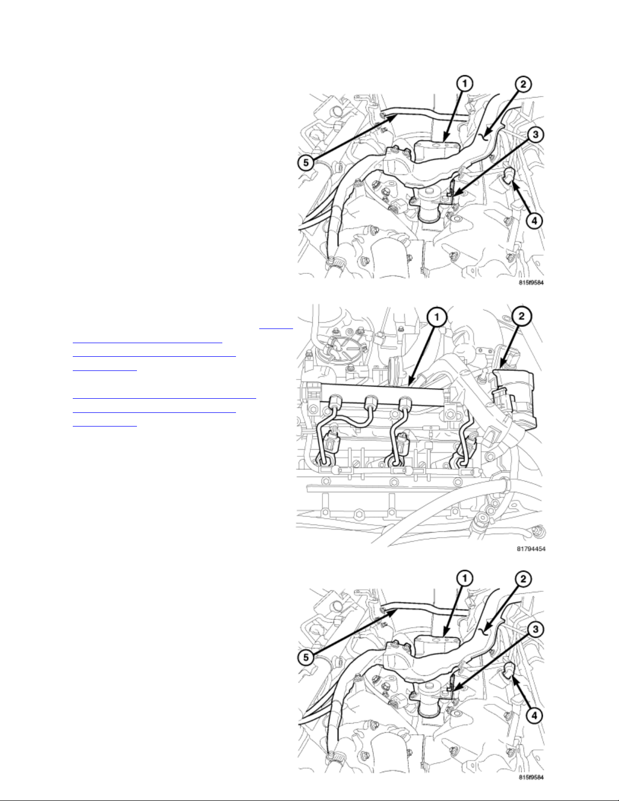
11. Remove the oil housing adapter (1).
12. Remove the rear engine lift bracket at the
intake manifold.
13. Remove the front engine lift bracket at
the cylinder heads.
14. Remove the left fuel rail and lines. (Refer
to 14 - FUEL SYSTEM/FUEL
INJECTION/FUEL INJECTOR REMOVAL)
15. Remove the right fuel rail and lines.
(Refer to 14 - FUEL SYSTEM/FUEL
INJECTION/FUEL INJECTOR REMOVAL)
16. Disconnect the engine harness (2) and
position aside.
17. Remove the swirl port actuator (3).
18. Remove the heater hose at the EGR
valve.
19. Remove the EGR control assembly.
Page 4

20. Remove the coolant hose at the
thermostat housing.
21. Remove the glow plug module.
22. Remove the throttle control assembly.
23. Remove the intake manifold.
24. Loosen the EGR cooler bolts to gain
access to the swirl valve linkage clips.
25. Remove the swirl valve linkage clips (2).
Page 5

INSTALLATION
1. Install the round clips (2) into the swirl
valve linkage.
2. Clean the intake manifold sealing surfaces.
3. Install new intake manifold gaskets.
12. Install the swirl valve actuator. (Refer to
9 - ENGINE/MANIFOLDS/ACTUATORSWIRL VALVE - INSTALLATION).
13. Install the fuel filter assembly (Refer to
14 - FUEL SYSTEM/FUEL
4. Install the EGR cooler.
5. Position the intake manifold and torque to 20.34
N.m (180 lbs. in.)
6. Install the throttle control assembly.
7. Instal the glow plug module.
8. Install the coolant hose at the thermostat
housing.
9. Install the EGR control assembly.
10. Install the EGR control assembly chamber
retaining bolts.
11. Install the EGR control assembly retaining
bracket.
Page 6

DELIVERY/FUEL FILTER - INSTALLATION).
14. Install the fuel lines. (Refer to 14 - FUEL SYSTEM/FUEL DELIVERY/FUEL LINES -
INSTALLATION)
15. Position and connect the engine harness.
16. Install the front lifting bracket.
17. Install rear lifting bracket.
18. Install the EGR tube.
19. Install the turbocharger. (Refer to 11 - EXHAUST SYSTEM/TURBOCHARGER
SYSTEM/TURBOCHARGER - INSTALLATION)
20. Install the engine compartment lower silencer.
21. Fill the cooling system. (Refer to 7 - COOLING - STANDARD PROCEDURE)
22. Install the vapor control valve.
23. Instal the charge air outlet tube (4).
24. Install the charge air resonator.
25. Install the air cleaner assembly. (Refer to 9 - ENGINE/AIR INTAKE SYSTEM/AIR
CLEANER HOUSING - INSTALLATION)
26. Install the engine cover. (Refer to 9 - ENGINE - INSTALLATION)
27. Connect the batteries. (Refer to 8 - ELECTRICAL/BATTERY SYSTEM/CABLES -
INSTALLATION)
Page 7

Linkage-Swirl Valve
DESCRIPTION
The intake manifolds feature swirl intake
ports to reduce particulates at low engine
speeds. Each cylinder incorporates one swirl
port and one charge port. The swirl ports can
be closed by the swirl valves. The valves are
connected together via a linkage which is
operated by the swirl valve actuator.
The swirl valves are normally open by spring
tension. The spring is integral with the swirl
valve actuator. In the lower engine speed and
load range, the swirl valves are closed by the
swirl valve actuator. The entire air mass
flows through the charge ports only, which
results in greater swirling. The increased
swirling produces uniform combustion for better engine performance and reduction of
particulates. As rotational speed and load increases, the swirl valves open, so that optimal
swirling and the required air mass are provided for the current operating conditions.
The linkage between the swirl valve actuator
and the intake manifold has two different
style clips. The square clip (1) is a two piece
design, and the round clip (2) is a one piece
design.
Page 8

REMOVAL
1. Disconnect negative battery cable. (Refer
to 8 - ELECTRICAL/BATTERY
SYSTEM/CABLES - REMOVAL)
2. Remove the engine cover. (Refer to 9 -
ENGINE - REMOVAL)
3. Drain the coolant. (Refer to 7 - COOLING
- STANDARD PROCEDURE)
4. Remove the strut tower support (2).
5. Remove the intake air housing and tube.
(Refer to 9 - ENGINE/AIR INTAKE
SYSTEM/AIR CLEANER HOUSING REMOVAL)
6. Remove the charge air cooler tube (4).
7. Remove the resonator.
8. Remove the EGR tube.
CAUTION: Observe the position of the
turbocharger oil passage housing and
gasket. Failure to properly position the gasket during assembly will result in immediate
turbocharger failure after assembly.
9. Remove the turbocharger (3). (Refer to 11 - EXHAUST SYSTEM/TURBOCHARGER
SYSTEM/TURBOCHARGER - REMOVAL)
10. Disconnect the engine harness and
position aside.
11. Disconnect the swirl valve actuator
connector.
12. Remove the swirl valve actuator (3) clips.
13. Remove the swirl valve actuator.
Page 9

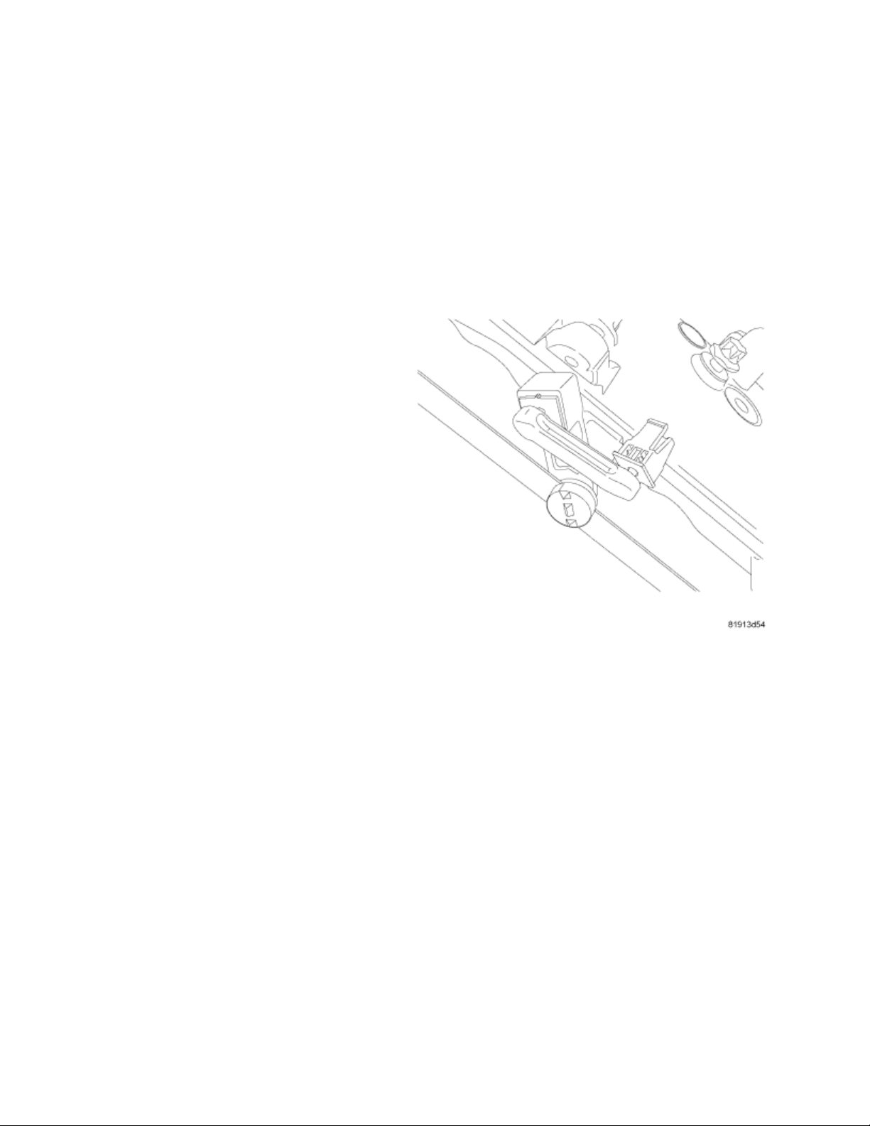
INSTALLATION
1. Assemble the two halves of the square clip
around the actuator arm, and place a 5/16” Oring (2) around the base of the clip (1) to hold
it together.
2. Position the clip into the actuator arm and push
the clip partially into the arm.
3. Cut the O-ring and press the clip the rest of the
way into the actuator arm. Make sure the clip
clicks into place.
Page 10

4. Install the swirl valve actuator. Tighten the bolts to 8 nm (44 lbs. in.).
5. Connect the swirl valve connector.
6. Position and connect the engine harness.
CAUTION: Observe the position of the turbocharger oil passage housing and gasket.
Failure to properly position the gasket during assembly will result in immediate
turbocharger failure after assembly.
7. Install the turbocharger. (Refer to 11 - EXHAUST SYSTEM/TURBOCHARGER
SYSTEM/TURBOCHARGER - INSTALLATION)
8. Install the EGR tube.
9. Install the resonator.
10. Install the charge air cooler tube (4).
11. Install the air cleaner housing and air
tube. (Refer to 9 - ENGINE/AIR INTAKE
SYSTEM/AIR CLEANER HOUSING INSTALLATION)
12. Install the strut tower support (2).
13. Fill the cooling system. (Refer to 7 -
COOLING - STANDARD PROCEDURE)
14. Install the engine cover. (Refer to 9 -
ENGINE - INSTALLATION)
15. Connect the battery. (Refer to 8 -
ELECTRICAL/BATTERY
SYSTEM/CABLES - INSTALLATION)
 Loading...