

Mercedes-Benz
S 32
0
S42
0
S
500
Operator's Manual
1

Product information
Kindly observe the following in your own best interest:
We recommend using Mercedes-Benz original parts as well as conversion parts and accessories explicitly approved by us for
your vehicle model. We have tested these parts to determine their reliability, safety and their special suitability for MercedesBenz vehicles.
We are unable to make an assessment for other products and therefore cannot be held responsible for them, even if in individual cases
an official approval or authorization by governmental or other agencies should exist. Use of such parts and accessories could
adversely affect the safety, performance or reliability of your vehicle. Please do not use them. Mercedes-Benz original parts as well as
conversion parts and accessories approved by us are available at your authorized Mercedes-Benz Center where you will receive
comprehensive information, also on permissible technical modifications, and where proper installation will be performed.
Our company and staff congratulate you on the purchase of your new Mercedes-Benz.
Your selection of our product is a demonstration of your trust in our company name. Further, it exemplifies your desire to own an
automobile that will be as easy as possible to operate and provide years of service.
Your Mercedes-Benz represents the efforts of many skilled engineers and craftsmen. To ensure your pleasure of ownership, and
for your safety and that of your passengers, we ask you to make a small investment of your time:
• Please read this manual carefully before putting it aside. Then return it to your vehicle where it will be handy for
your reference.
• Please abide by the recommendations contained in this manual. They are designed to acquaint you with the
operation of your Mercedes-Benz.
• Please abide by the warnings and cautions contained in this manual. They are designed to help improve the safety
of the vehicle operator and occupants.
•
We extend our best wishes for many miles of safe, pleasurable driving.
DaimlerChrysler AG
2

Operator's manual
This Operator's Manual contains a great deal of useful information.
We urge you to read it carefully and familiarize yourself with the vehicle before driving.
For your own safety and longer service life of the vehicle, we urge you to follow the instructions and warnings contained in this
manual. Ignoring them could result in damage to the vehicle or personal injury to you or others. Vehicle damage caused by failure to
follow instructions is not covered by the Mercedes-Benz Limited Warranty.
Your vehicle may have some or all of the equipment described in this manual. Therefore, you may find explanations for optional
equipment not installed in your vehicle. If you have any questions about the operation of any equipment, your authorized MercedesBenz Center will be glad to demonstrate the proper procedures.
Owner’s Service and Warranty Policy
The Owner’s Service and Warranty Information Booklet contains detailed information about the warranties covering your
Mercedes-Benz, including:
• New Car Limited Warranty,
• Emission System Warranty,
• Emission Performance Warranty,
• State Warranty Enforcement Laws (Lemon Laws).
3

Important notice for California retail buyers of Mercedes-Benz automobiles
Under California law you may be entitled to a replacement of your vehicle or a refund of the purchase price, if Mercedes-Benz USA,LLC
or its authorized Mercedes-Benz Center fails to conform the vehicle to its express warranties after a reasonable number of repair attempts
during the period of one year or 12 000 miles from original delivery of the vehicle. A reasonable number of repair attempts is presumed for
a retail buyer (1) if the vehicle is out of service by reason of repair of substantial nonconformities for a cumulative total of more than 30
calendar days or (2) the same substantial non-conformity has been subject to repair four or more times and you have at least once
directly notified us in writing of the need to repair the non-conformity and have given us an opportunity to perform the repair
ourselves. Notifications should be sent to the nearest Mercedes-Benz Regional Office listed in the Service and Warranty
Information Booklet.
Maintenance
The Service Booklet describes all the necessary maintenance work which should be performed at regular intervals.
Always have the Service Booklet with you when you take the vehicle to your authorized Mercedes-Benz Center for service.
The service advisor will record each service in the booklet for you.
Roadside assistance
The Mercedes-Benz Roadside Assistance Program provides factory trained technical help in the event of a breakdown. Calls to the
toll-free Roadside Assistance number:
1-800-222-0100 (inthe USA) only
will be answered by Mercedes-Benz Client Assistance Representatives 24 hours a day, 365 days a year.
For additional information refer to the Mercedes-Benz Roadside Assistance Program brochure in your glove box.
4

Change of address or ownership
If you change your address, be sure to send in the "Change of Address Notice" found in the Owner's Service
and Warranty Policy Booklet. It is in your own interest that we can contact you should the need arise.
If you sell your Mercedes, please leave all owner's literature with the vehicle to make it available to the next owner.
If you bought this vehicle used, be sure to send in the "Notice of Purchase of Used Car" found in the Owner's
Service and Warranty Policy Booklet.
Operating your vehicle outside the USA or Canada
If you plan to operate your vehicle in foreign countries, please be aware that service facilities or replacement
parts may not be readily available.
Certain Mercedes-Benz models are available for delivery in Europe under our European Delivery Program.
For details, consult your authorized Mercedes-Benz dealer or write to:
In the USA: In Canada:
Mercedes-Benz USA, Mercedes-Benz Canada, Inc.
LLCEuropean Delivery Department European Delivery Department
One Mercedes Drive 849 Eglinton Avenue East
Montvale, NJ 07645 Toronto, Ontario M4G 2L5
5

We continuously strive to improve our product, and ask for your understanding that we reserve the right to make changes in design and
equipment. Therefore, information, illustrations and descriptions in this Operator's Manual might differ from your vehicle.
Optional equipment is also described in this manual, including operating instructions wherever necessary. Since they are special-order
items, the descriptions and illustrations herein may vary slightly from the actual equipment of your vehicle.
If there are any equipment details that are not shown or described in this Operator's Manual, your authorized MercedesBenz Center will be glad to inform you of correct care and operating procedures.
The Operator's Manual and Service Booklet are important documents and should be kept with the vehicle.
6

Check Regularly and Before a Long Trip
See Index
The First 1000 Miles (1500 km)
The more cautiously you treat your vehicle during the break-in period, the more satisfied you will be with its performance
later on. Therefore, drive your vehicle during the first 1500 km (1000 miles) at moderate vehicle and engine-speeds.
During this period, avoid heavy loads (full throttle driving) and high RPM (no more than 2/3 of maximum permissible speed in
each gear as indicated on the speedometer).
Avoid accelerating by kickdown. It is not recommended to brake the vehicle by manually shifting to a lower gear. We
recommend to select positions "3" or "2"only at moderate speeds (for hill driving).
After 1000 miles (1500 km) speeds may be gradually increased to the permissible maximum
Maintenance
We strongly recommend that you have your vehicle serviced by your authorized Mercedes-Benz dealer, in accordance with the
Maintenance Booklet.
Failure to have the vehicle maintained in accordance with the Maintenance Booklet may result in vehicle damage not covered by
the Mercedes-Benz Limited Warranty.
Radio Transmitters
Warning!
Never operate radio transmitters equipped with a built-in or attached antenna (i.e. without the telephone
connected to an external antenna) from inside the vehicle while the engine is running. Doing so could lead
to a malfunction of the vehicle's electronic system, possibly resulting in an accident and personal injury.
Radio transmitters, such as a portable telephone or a citicens band unit should only be used inside the passenger compartment, if
they are connected to a Mercedes-Benz approved antenna that is installed on the outside of the vehicle.
7

Introduction
(ETR)
Product information 2 Central Locking Switch 34 First Aid Kit 68
Operator's manual 4 Trunk 35 Stowing Things in the Vehicle 69
Consumer Information
Problems with your vehicle 154
Reporting Safety Defects 155 Anti-Theft Alarm System 38 Sliding /Pop-up Roof 70
Index
Instruments and controls Multicontour Backrest
Instruments and controls
Instrument Cluster 12 Power Seats, Rear 45 Display Illumination 74
Indicator Lamp Symbols 13 Armrest, Rear 46 Trip Odometer 74
Catalytic Converter
Starting and Turning Off the Engine 16 Power Head Restraints, Rear 47 Garage Door Opener 75
Driving Instructions 17 Adjustable Steering Wheel 48 Antenna 76
Operation Restraint system (SRS) 49
Automatic Climate Control
Basic Setting – Automatic Mode 24 Deactivation 52 Drinking and driving 78
Defogging Windows 24 Self Test 53 Parking Brake 78
Defrosting
Rear Window Defroster 24 Airbag 54 Automatic Transmission 79
Air circulation 25 Child Restraint 57 Cruise Control 83
Activated Charcoal Control
Rear passenger compartment Combination Switch 60 Charge Indicator Lamp 88
Adjustable Air Outlet 27 Exterior Lamp Switch 62 Engine Oil Pressure Gauge
Climate Control 27 Night Security Illumination 63 Low Engine Oil Level Warning Lamp 88
Car keys 28 Inside Rear View Mirror 63 Engine Oil Consumption 89
Start Lock-out 29 Exterior Rear View Mirror 63 Fuel Consumption Gauge 89
Central Locking System
Radio Frequency Infrared Remote Control
Doors
153
Power Window and Sliding/Pop-Up Roof
Power Closing Ass. f Door and Trunk lid
158 Power Seats, Front 39 Power Windows 71
Lumbar Support 42 Rear Window Sunshade 73
Armrest, Front 43 Shelf Below Rear Window 73
10 Heated Seats 44 Instrument Lamps 74
15 Head Restraints, Rear 46 Clock 74
Seat belts and Supplemental
Seat belts 49 Driving
22 Baby Smart Airbag System
24 Emergency tensioning retractor
26 Steering lock 59 Parking Assist (Parktronic) 85
29 Sun Visors 65 Fuel Reserve and Fuel Cap 89
Vanity mirrors 65 Placement Warning Lamp 89
29 Interior Lighting 66
33 Storage Compartments 67
36 Ashtrays 69
37 Lighter 69
42 Trunk Lid Release switch 73
Cellular telephone 76
53 Driving off 78
8

Outside Temperature Indicator 90 Checking Engine Oil Level 108 Technical Data. Fuels,
Automatic Trans. Fluid Level
BENZ
Tachometer 90
Coolant Temperature Gauge 90 Spare Wheel 109 Information
Low Engine Coolant Level
Warning Lamp 91 Vehicle Jack 110 Identification Plates 140
Low Windshield and Headlamp Vehicle Tools 110 Warranty Coverage 141
Washer Fluid Level Warning
Lamp 91 tool box 110 S 420 144
Exterior Lamp Failure Indicator Wheels 111 S 500 146
Lamp 92 Changing Wheels 112 Fuels, Coolants, Lubricants etc. 148
Brake Pad Wear Indicator Lamp 92 Tire in Inflation Pressure 115 Capacities 148
Brake Warning Lamp 93 Exterior Lamps 116 Engine Oils 150
Flexible Service System (FSS)
Antilock Brake System (ABS) 95 Fuses 125 Air Conditioner Refrigerant 150
Brake Assist System (BAS) 96 Jump Starting 125 Brake Fluid 150
Acceleration Slip Regulation (ASR) 97 Towing the Vehicle 127 Premium Unleaded Gasoline 150
Electronic Stability program (ESP) 99 Cleaning and Care of the Vehicle 128 Fuel Requirements 151
Adaptive damping system (ADS) 101 Testing Infrared Remote Control 132 Gasoline Additives 151
Emission Control
On-Board Diagnostic System 102 Rear Seat Cushion 134 Service and Literature 163
Traveling Abroad 103
Winter Driving 103 Replacing Wiper Blades 135
Snow Chains 103 Manual Closing of Trunk Lid 136
Practical Hints Roof Rack 137
Hood 106 MERCEDESChecking Coolant Level 107 Spare Part Service 138
Adding Coolant 107
Trunk Lamp 109
Storage compartment below vehicle Technical Data S 320 142
93 Battery 124 Engine Oils Additives 150
102 Front Head Restraints 133 Coolants 152
Emergency Operation of Sliding Roof
Manual Release of Fuel Filler Flap 136
Layout of Poly-V-Belt Drive 137
109 Coolants, Lubricants etc. Consumer
134 Check Regularly Before a long Trip 164
9

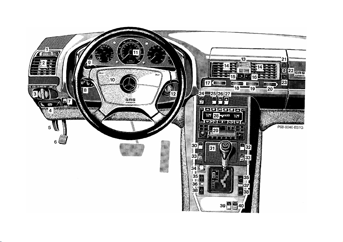
Instruments and Controls For more detailed descriptions see Index
14
1 Left Front Parktronic warning indicator 21 Storage/eyeglasses compartment
2
Side air outlet, adjustable 22 Lock for storage/eyeglasses compartment and eye glove
3
Exterior lamp switch 23
4 Parking brake release 24 Switch for rear seat head restraints
5
Hood lock release 25 Trunk lid release switch
6 Parking brake pedal 26 Central locking switch, Indicator for anti-theft alarm
7 Steering wheel adjustment switch 27 Hazard warning flasher switch
8 Combination switch 28 Automatic climate control, Power window defroster switch
Cruise control 29 Radio
9
10 Horn, airbag 30 ASR or ESP control switch
11 Instrument cluster 31 Ashtray with lighter
12 Steering lock with ignition/starter 32 Adaptive damping system adjustment switch
13 Right front Parktronic warning indicator 33 Seat heater switch
Center air outlet, adjustable 34 Mirror adjustment switch
15 Heated air supply button - center air outlet 35 Power window switch, front doors
16 Non heated/cooled air supply button - center air outlet 36 Power window safety switch, rear doors
17 Air volume control for left air outlet 37 Airbag Off indicator lamp
18 Air volume control for left center air outlet 38 Power window switches, rear doors
19 Air volume control for right center air outlet 39 Parktronic switch
20 Air volume control for right air outlet 40 Switch for rear window sunshade
Glove box (illuminated with key in steering lock position 1 or 2)
Activated charcoal filter switch
system
10
11
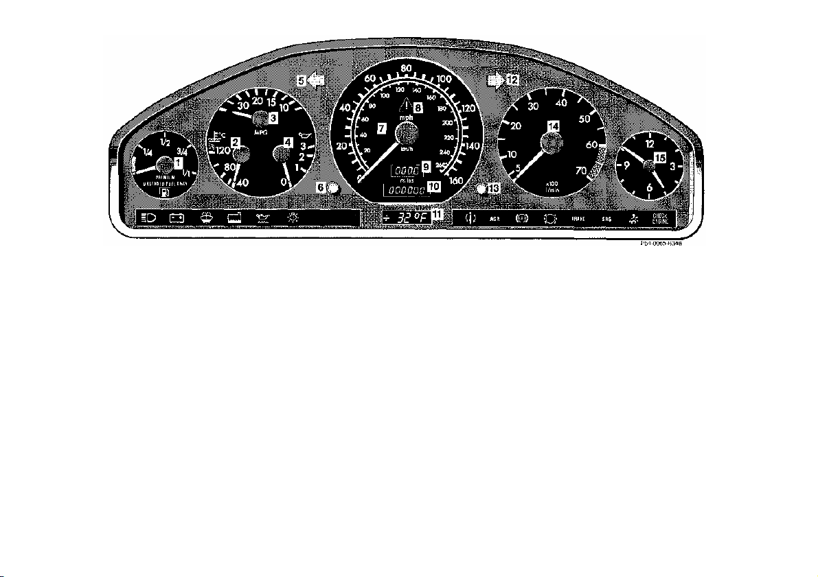
Instrument Cluster
ASR function indicator lamp (yellow).
Fuel gauge with reserve and fuel cap placement warning
1
lamp (yellow). See Index
Coolant temperature gauge. See Index
2
Fuel consumption gauge. See Index
3
Engine oil pressure gauge (bar). See Index
4
Left turn signal indicator lamp (green). See Index
5
Knob for instrument lamps and trip odometer and FSS.
6
See Index
Speedometer See Index
7
8
ESP function indicator lamp (yellow). See Index.
Main/trip odometer. See Index
9
Outside temperature indicator. See Index
10
Right turn signal indicator lamp (green) See Index
11
Knob for setting clock. See Index
12
Tachometer. See Index
13
Clock. See Index
14
12
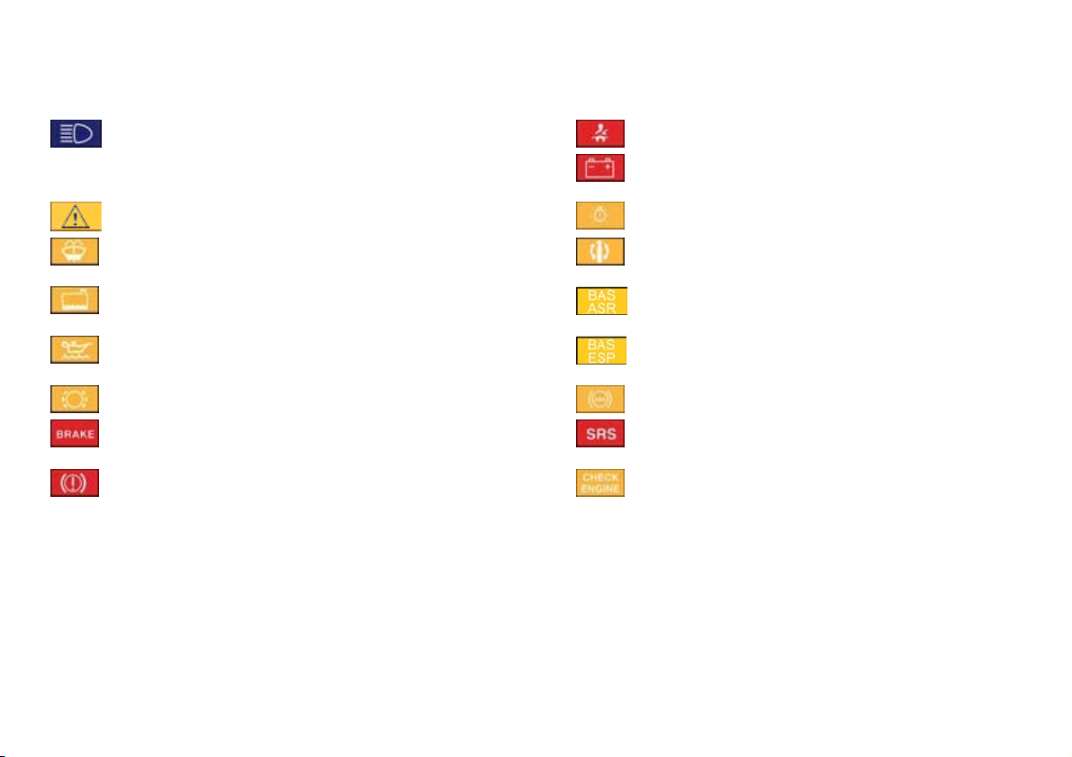
Indicator Lamp Symbols
BAS malfunction. See Index
on. See Index
Function Indicator Lamp
High beam
Warning Lamp
(should go out with the engine running unless)
ESP Adjust driving to road condition. See Index Exterior lamp failure. See Index.
Fluid level for windshield and headlamp washer
system low. See Index.
Coolant level low. See Index.
Engine oil level low. See Index. BAS malfuncti
Brake pads worn down. See Index. ABS malfunction. See Index
Brake fluid low (except Canada). Parking brake
engaged. See Index.
Brake fluid low (Canada only). Parking brake
engaged. See Index.
Fasten seat belts. See Index.
Battery not being charged properly. See Index
ADS malfunction. See Index
ASR malfunction. See Index
ESP malfunction. See Index
SRS malfunction. See Index
Engine malfunction.
If the lamp comes on when the engine is running, it
indicates a malfunction of the 02-sensor on Federal
version vehicles, and fuel injection system or
emission control system on the California version
vehicles. In either case, we recommend that you
have the malfunction checked as soon as possible.
See Index.
13

Additional Function Indicator Lamps
in the Odometer Display
Start Lock-Out malfunction. See Index. Passenger Airbag automatically switched off.
FSS indicator (days). See Index
FSS indicator (distance). See Index
Additional Function Indicator Lamp on the Center
Console
See Index
14

Catalytic Converter
Caution!
Warning!
Your MERCEDES-BENZ is equipped
with monolithic type catalytic
converters, an important element in
conjunction with the O2sensor to
achieve substantial control of the
pollutants in the exhaust emissions.
Keep your vehicle in proper operating
condition by following our recommended maintenance instructions
as outlined in your Maintenance
Booklet.
To prevent damage to the catalytic
converters, use only premium unleaded
gasoline in this vehicle.
Any noticeable irregularities in engine
operation should be repaired promptly.
Otherwise, excessive unburned fuel
may reach the catalytic converter
causing it to overheat, which could
start a fire.
As with any vehicle, do not idle, park
or operate this vehicle in areas where
combustible materials such as grass,
hay or leaves can come into contact
with the hot exhaust system, as these
materials could be ignited and cause
a vehicle fire.
15

Starting and Turning Off the Engine
Important!
Turning Off
Before Starting
Ensure that parking brake is engaged
and that selector lever is in position "P"
or "N". Turn key in steering lock to
position 2. The charge indicator lamp
should come on.
Starting
Do not depress accelerator.
Turn key in steering lock clockwise to
the stop. Release key only when the
engine is firing regularly.
Due to the installed starter non-repeat
feature, the key must be turned
completely to the left before attempting
to start the engine again.
Observe the oil pressure gauge
immediately after starting the engine.
In a very cold engine the oil pressure
will rise slowly after the engine has
started. Do not speed up the engine
before pressure is registered on the
pressure gauge. If you do not see the
gauge register oil pressure, stop the
engine and have it checked.
The charge indicator lamp should go
out as soon as the engine has started.
In areas where temperatures frequently
drop below -4°F (-20°C) we
recommend that an engine block heater
be installed. Your authorized
Mercedes-Benz dealer will advise you
on this subject.
Turn the key in the steering lock to
position 0 to stop the engine.
The key can only be removed with the
foot off the brake pedal and the selector
lever in position "P".
16

Driving Instructions
Warning!
If you feel a sudden significant
vibration or ride disturbance, or you
suspect that possible damage to your
vehicle has occurred, you should
turn on the hazard flashers, carefully
slow down, and drive with caution to
an area which is a safe distance from
the roadway.
Brakes
Warning!
After driving in heavy rain for some
time without applying the brakes or
through water deep enough to wet
brake components, the first braking
action may be somewhat reduced
and increased pedal pressure may be
necessary. Be sure to maintain a safe
distance from vehicles in front.
If the parking brake is released and the
brake warning lamp in the instrument
cluster stays on, the brake fluid level in
the reservoir is too low.
Brake pad wear or a leak in the system
may be the reason for low brake fluid
in the reservoir.
Have the brake system inspected at an
authorized Mercedes-Benz dealer
immediately.
Inspect the tires and under the
vehicle for possible damage. If the
vehicle or tires appear unsafe, have it
towed to the nearest Mercedes-Benz
or tire dealer for repairs.
Power Assistance
When the engine is not running, the
brake and steering systems are
without power assistance. Under
these circumstances, a much greater
effort is necessary to stop or steer the
vehicle.
Resting your foot on the brake pedal
will cause excessive and premature
wear of the brake pads.
It can also result in the brakes
overheating thereby significantly
reducing their effectiveness. It may
not be possible to stop the car in
sufficient time to avoid an accident.
The condition of the parking brake
system is checked each time the car is
in the shop for the required service.
All checks and maintenance work on
the brake system should be carried out
by an authorized MERCEDES-BENZ
dealer.
Install only brake pads and brake fluid
recommended by Mercedes-Benz.
Warning!
If other than recommended brake
pads are installed, or other than
recommended brake fluid is used,
the braking properties of the vehicle
can be degraded to an extent that
safe braking is substantially
impaired. This could result in an
accident.
17
Caution!
When driving down long and steep
grades, relieve the load on the brakes
by shifting into a lower gear. This helps
prevent overheating of the brakes and
reduces brake pad wear.
Specified tire pressures must be
maintained. This applies particularly if
the tires are subjected to high loads
(e.g. high speeds, heavy loads, high
ambient temperatures).
Warning!
After hard braking, it is advisable to
drive on for some time, rather than
immediately parking, so the air stream
will cool down the brakes faster.
Tires
Tread wear indicators (TWI) are
required by law. These indicators are
located in six places on the tread
circumference and become visible at a
depth of approx. 2 mm (1/16 in), at
which point the tire is considered worn
and should be replaced.
The tread wear indicator appears as a
solid band across the tread.
Warning!
Do not allow your tires to wear down
too far. With less than 1.5 mm (1/16
in) of tread, the adhesion properties
on a wet road are sharply reduced.
Depending upon the weather and/or
road surface (conditions), the tire
traction varies widely.
Do not drive with a flat tire. A flat
tire affects the ability to steer or
brake the vehicle. You may lose
control of the car. Continued driving
with a flat tire or driving at high
speed with a flat tire will cause
excessive heat build-up and possibly
a fire, or tire blowout.
Aquaplaning
Depending on the depth of the water
layer on the road, aquaplaning may
occur, even at low speeds and with new
tires. Avoid track grooves in the road
arid apply brakes cautiously in the rain.
18

Tire Traction
he tire rating, local speed limits
fore
vehicle.
Tire Speed Rating
Parking
The safe speed on a wet, snow covered
or icy road is always lower than on a
dry road.
You should pay particular attention to
the condition of the road as soon as the
prevailing temperatures fall close to the
freezing point.
Warning!
If ice has formed on the road, tire
traction will be substantially
reduced. Under such weather
conditions, drive, steer and brake
with extreme caution.
We recommend M+S rated radial-ply
tires for the winter season for all four
wheels to insure normal balanced
handling characteristics.
On packed snow, they can reduce your
stopping distance as compared with
summer tires. Stopping distance,
however, is still considerably greater
than when the road is not snow or ice
covered.
Your vehicle is factory equipped with
"H" -rated tires, which have a European
speed rating of 130 mph (210 km/h). An
electronic speed limiter prevents your
vehicle from exceeding the speed rating.
Despite t
should be obeyed. Use prudent driving
speeds appropriate to prevailing
conditions.
Warning!
Even when permitted by law, never
operate a vehicle at speeds greater
than the maximum speed rating of
the tires.
Exceeding the maximum speed for
which tires are rated can lead to
sudden tire failure causing loss of
vehicle control and resulting in
personal injury and possible death.
Warning!
To reduce the risk of personal injury
as a result of vehicle movement, be
turning off the engine and leaving the
vehicle always:
1. Keep foot on brake pedal.
2. Firmly depress parking brake
pedal.
3. Engage first or reverse gear
(selector lever position "P" in the
case of automatic transmissions).
4. Slowly release brake pedal.
5. Turn front wheels towards the
road curb,
6. Turn the key to steering lock
position 0 and remove.
7. Take your key and lock vehicle
when leaving.
Important!
It is advisable to set the parking brake
whenever parking or leaving the
In addition, engage first or reverse gear
(selector lever position "P").
When parking on hills, always set the
parking brake.
19

Winter Driving Instructions
The most important rule for slippery or
icy roads is to drive sensibly and to
avoid abrupt acceleration, braking and
steering action. Do not use the cruise
control system under such conditions.
When the vehicle is in danger of
skidding, declutch, or in case of
automatic transmission move selector
lever to position "N". Try to keep the
vehicle under control by corrective
steering action.
Road salts and chemicals can adversely
affect braking efficiency. Increased
pedal force may become necessary to
produce the normal brake effect. We
therefore recommend depressing the
brake pedal repeatedly when traveling
on salt-strewn roads at length. This can
bring road salt impaired braking
efficiency back to normal. A
prerequisite is, however, that this is
possible without endangering other
drivers on the road.
If the vehicle is parked after being
driven on salt treated roads, the braking
efficiency should be tested as soon as
possible after driving is resumed while
observing the safety rules in the
previous paragraph.
Warning!
If the vehicle becomes stuck in snow,
make sure that snow is kept clear of
the exhaust pipe and from around
the vehicle with engine running.
Otherwise, deadly carbon monoxide
(CO) gases may enter vehicle interior
resulting in unconsciousness and
death.
To assure sufficient fresh air
ventilation, open a window slightly
on the side of the car that is out of
the wind.
Deep Water
Caution!
Do not drive through flooded areas or
water of unknown depth.
If you must drive through deep water,
drive slowly to prevent water from
entering the engine compartment or
being ingested by the air intake,
possibly causing damage to electrical
components or wiring, to engine or
transmission that is not covered by the
Mercedes-Benz Limited Warranty.
Passenger Compartment
Warning!
Always fasten items being carried as
securely as possible.
In an accident, during hard braking
or suden maneuvers, loose items will
be thrown around inside the vehicle,
and cause injury to vehicle occupants unless the items are securely
fastened in the vehicle.
20

Operation
21
Automatic Climate Control
The system is always at operational
readiness, except when manually
switched off.
The automatic climate control only
operates with the engine running
The temperature selector should be left
at the desired temperature setting. The
temperature selected is reached as
quickly as possible.
The system will not heat or cool any
quicker by setting a higher or lower
temperature.
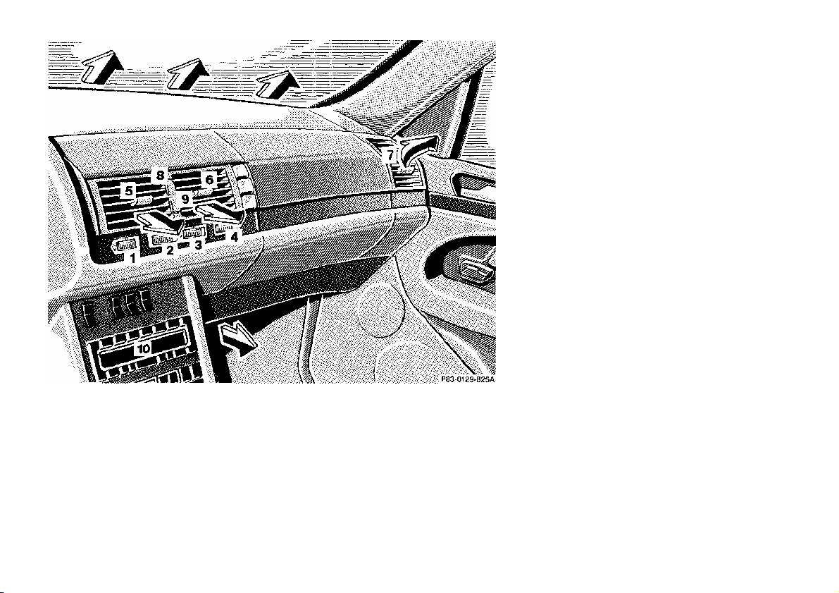
1 Air volume control
for left air outlet,
turn left to open
2 Air volume control
for left center air outlet,
turn left to open
3 Air volume control
for right center air outlet,
turn left to open
4 Air volume control
for right air outlet,
turn left to open
5 Left center air outlet,
adjustable
6 Right center air outlet,
adjustable
7 Side air outlet,
left and right,
adjustable
Push-buttons for center air outlets
8 Heated air supply
9 Non-heated/cooled air supply
Basic mode:
None of the push-buttons
(8 or 9) is pressed.
10 Display and Controls
22
The automatic climate control
removes considerable moisture from
the air during operation in the cooling
mode. It is normal for water to drip on
the ground through ducts in the
underbody.
The desired interior temperature can
be selected separately for the left and
right side of the passenger
compartment.
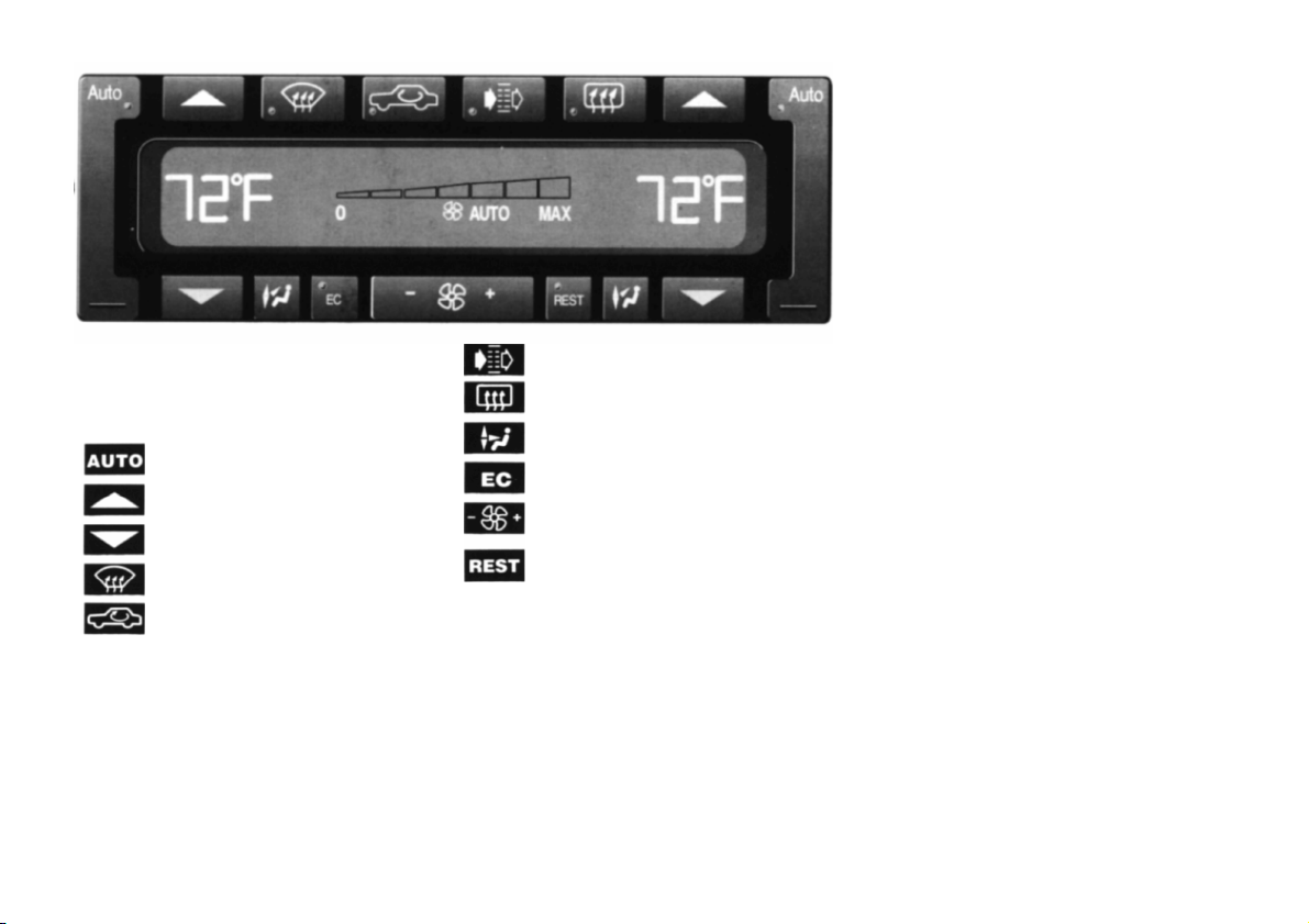
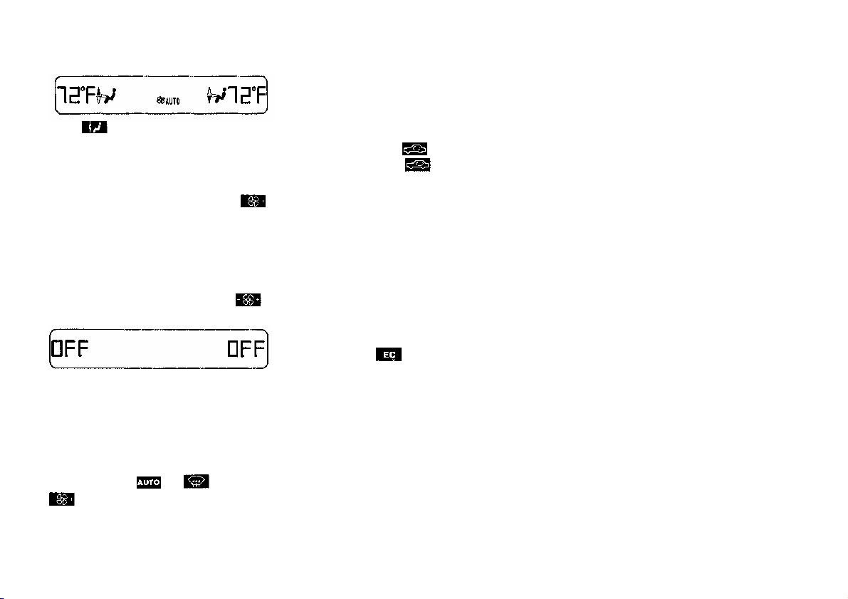
Display and Controls
Press to activate, indicator lamp is on
while activated.
Automatic mode
Raise temperature
Lower temperature
Defrost
Air recirculation
Activated charcoal filter
Rear window defroster
Air distribution, manual
Economy mode
Air volume, manual
Residual engine heat
utilization
Important!
This vehicle is equipped with an
air conditioner system that uses
HFC-134a (ozone-friendly hydrofluorocarbon) as a refrigerant. Repairs
should always be performed by a
qualified technician, and refrigerant
should be collected in a recovery
system for recycling.
23
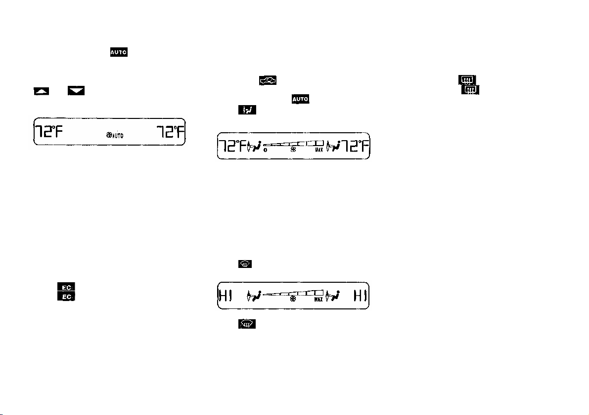
Basic Setting - Automatic Mode
Press left and right for
automatic mode.
Special Settings
(use only for short duration)
Defogging Windows
Rear Window Defroster
Turn key in steering lock to
position 2.
Simultaneously press both
and for temperature setting of
72°F.
Air volume and distribution are
controlled automatically.
This setting can be used all year around.
Economy
The function of this setting corresponds
to the automatic mode. However,
because the air conditioning compressor
will not engage (fuel savings), it is not
possible to air condition in this setting.
Press button to activate.
Press button once again to return
to previous setting.
Switch off button.
Press left and right buttons.
Press button repeatedly until air is
directed upward.
Turn wheels (1 and 4) left to open left
and right air outlets (7). Adjust air
outlets upward.
Defrosting
Turn wheels (1 and 4) left to open left
and right air outlets (7). Adjust air
outlets upward.
Press button once again to return
to previous setting.
Press button. Maximum heated
and automatically controlled amount of
air is directed to the windshield and
side windows.
To select, press button.
To cancel, press button again.
Note:
Heavy accumulation of snow and ice
should be removed before activating
the defroster.
The rear window defroster uses a large
amount of power. To keep the battery
drain to a minimum, turn off the
defroster as soon as the window is
clear.
The defroster is automatically
turned off after a maximum of 12
minutes of operation.
If several power consumers are turned
on simultaneously, or the battery is
only partially charged, it is possible
that the defroster will automatically
turn itself off. When this happens, the
indicator lamp inside the switch starts
blinking.
As soon as the battery has sufficient
voltage, the defroster automatically
turns itself back on.
24
Air Distribution
Air Recirculation
Dust Filter
Press button repeatedly until
the requested symbol is displayed.
Air Volume
Press - or + side of rocker switch
until the requested blower speed is
attained. A choice of 7 blower speeds is
available.
To switch the automatic climate control
off, press - side of rocker switch
until symbol OFF is displayed.
The fresh air supply to the car interior
is shut off.
While driving, use this setting only
temporarily, otherwise the windshield
could fog up.
To switch the automatic climate control
on again, press , or + side of
- .
This mode can be selected to prevent
annoying odors or dust from entering
the car's interior.
Outside air is not supplied to the car's
interior.
To select, press button.
To cancel, press button
again.
The system will automatically
switch from recirculated air to
fresh air
• after approx. 5 minutes at
outside temperatures below
approx. 40°F (5°C),
• after approx. 30 minutes, at
outside temperatures above
approx. 40°F (5°C),
• after approx. 5 minutes, if
button is pressed.
Notes:
If the windows should fog up from the
inside, switch from recirculated air
back to fresh air.
At high outside temperatures, the
system automatically engages the
recirculated air mode thereby
increasing the cooling capacity
performance, switching to partially
fresh air within 20 minutes.
Dust particles (down to a certain size)
and pollen are filtered out before
outside air enters the passenger
compartment through the air
distribution system.
Notes:
Do not obstruct the air flow by placing
objects on the air flow-through exhaust
slots below the rear window.
Also keep the air intake grille in front
of windshield free of snow and
debris.
25

Activated Charcoal Filter
Notes:
Residual Engine Heat Utilization
To select, press button.
To cancel, press button
again.
An activated charcoal filter markedly
reduces bad odors and removes
pollutants from the air entering the
passenger compartment.
The blower speed is slightly increased
to supply a constant volume of air.
The system switches automatically to
the air recirculation mode, if the carbon
monoxide (CO) or nitric oxide (NOX)
of the outside air increases.
When pressing button or
, the filter is also switched off.
The automatic air recirculation does
not function when selecting the
Economy mode , or the outside
temperature is below 45°F (7°C).
The activated charcoal filter should be
switched off when windows fog up on
the inside, or if the passenger
compartment needs to be quickly
heated or cooled down.
With the engine switched off, it is
possible to continue heating the interior
for a short while.
Air volume and distribution are
controlled automatically.
To select:
Turn key in steering lock to position 1
or 0 or remove key. Close air outlet in
rear passenger compartment.
Press button.
This function selection will not activate
if the battery charge level is
insufficient.
To cancel:
Press button.
The system will automatically shut off
• if you turn key in steering lock
to position 2,
• after approx. 30 minutes,
• if the battery voltage drops.
26
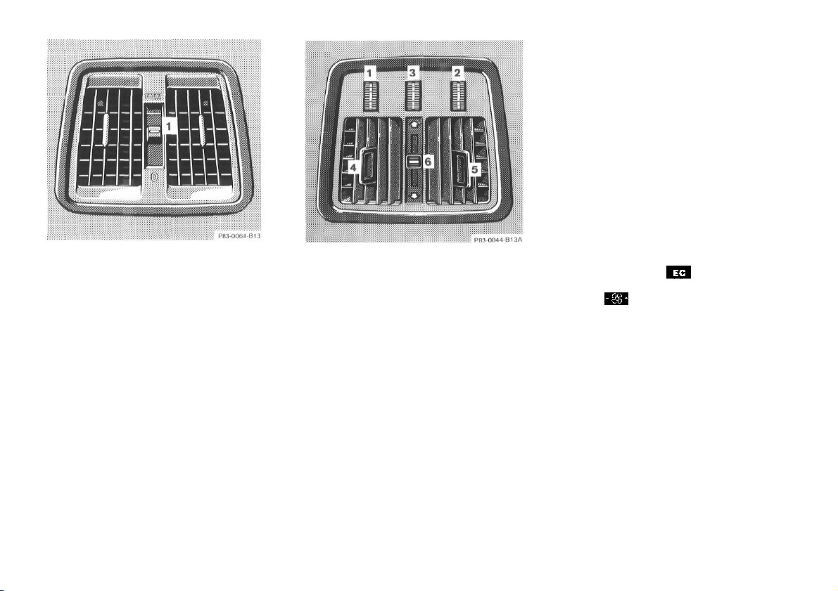
Rear Passenger Compartment
Adjustable Air Outlet
Vehicles without rear passenger
compartment climate control.
Rear Passenger Compartment
Climate Control
1 Temperature selector, left side
2 Temperature selector, right side
4 Adjustable air outlet, left side
5 Adjustable air outlet, right side
6 Air distribution slide
Top position: air flow from air
outlets (4 and 5).
Bottom position: air flow from air
outlets beneath front seats.
Intermediate positions can be
selected for a mixed air flow.
Note:
The rear passenger climate control
does not operate with automatic
climate control in mode or
switched off with the air volume
control .
Slide switch (1) up to open outlet for
fresh/cooled air only.
The air outlet is adjustable.
A basic setting in the white field of the
selector is recommended.
3 Air volume selector
The air volume can be varied
continuously. The air flow is switched
off with selector in position "0".
27
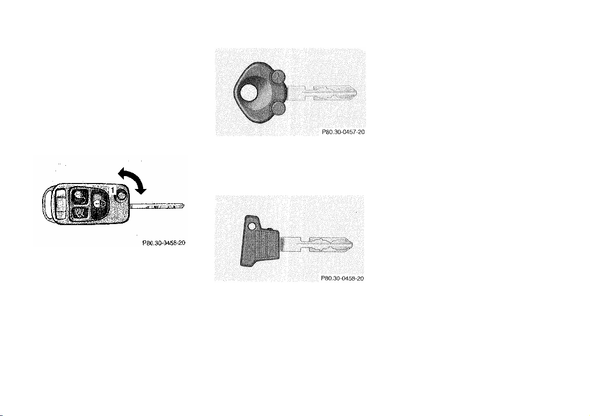
Car Keys
Included with your vehicle are
• 2 remote controls with
folding master keys,
• 1 Valet key,
• 1 Flat key.
Infrared Remote Control with
Folding Master Key
The infrared receivers are located in
the door front handles.
The valet key works only in the driver's
door lock and the steering lock.
Thevalet key will not workin the trunk
and storage compartments locks.
Notes:
Do not give the master key to an
unauthorized person.
We recommend that you carry the flat
key with you and keep it in a safe place
(e.g. your wallet) so that it is always
handy. Never leave the flat key in the
vehicle.
Warning!
When leaving the vehicle always
remove the key from the steering
lock. Do not leave children
unattended in the vehicle.
Unsupervised use of vehicle
equipment may cause serious
personal injury.
Obtaining Replacement Keys
The master key fits all locks on the car.
To release the key, press button (1).
The key unfolds from the holder by
itself.
The transmitter for the infrared remote
control is located in the key holder.
The flat key fits all locks on the Car.
Your vehicle is equipped with a theft
deterrent locking system requiring a
special key manufacturing process. For
security reasons, replacement keys can
only be obtained from your authorized
Mercedes-Benz dealer.
28
Starter Lock-Out
Central Locking System
Important!
Removing the key from the steering
lock activates the start lock-out. The
engine cannot be started.
Turning the key in the steering lock to
position 2 deactivates the start lock-out.
Note:
In case the engine cannot be started,
and the message START-ERROR
shows in the odometer display field,
the system is not operational. Contact
an authorized Mercedes-Benz dealer or
call 1-800-FOR-MERCedes.
Radio Frequency and Infrared
Remote Control
The master key has an integrated radio
frequency and infrared remote control.
Due to the extended operational range
of the remote control, it could be
possible to unintentionally lock or
unlock the vehicle by pressing the
transmit button.
The vehicle doors, trunk and fuel filler
flap can be centrally locked and
unlocked.
Closing the windows and sliding/popup roof can only be done with the
infrared portion of the remote control.
Aim transmitter eye (4) at a receiver (5
or 6) and press transmit button.
With vehicle centrally locked, the trunk
can also be opened by using the remote
control.
If the key is inserted in steering lock,
the vehicle cannot be locked or
unlocked with the remote control.
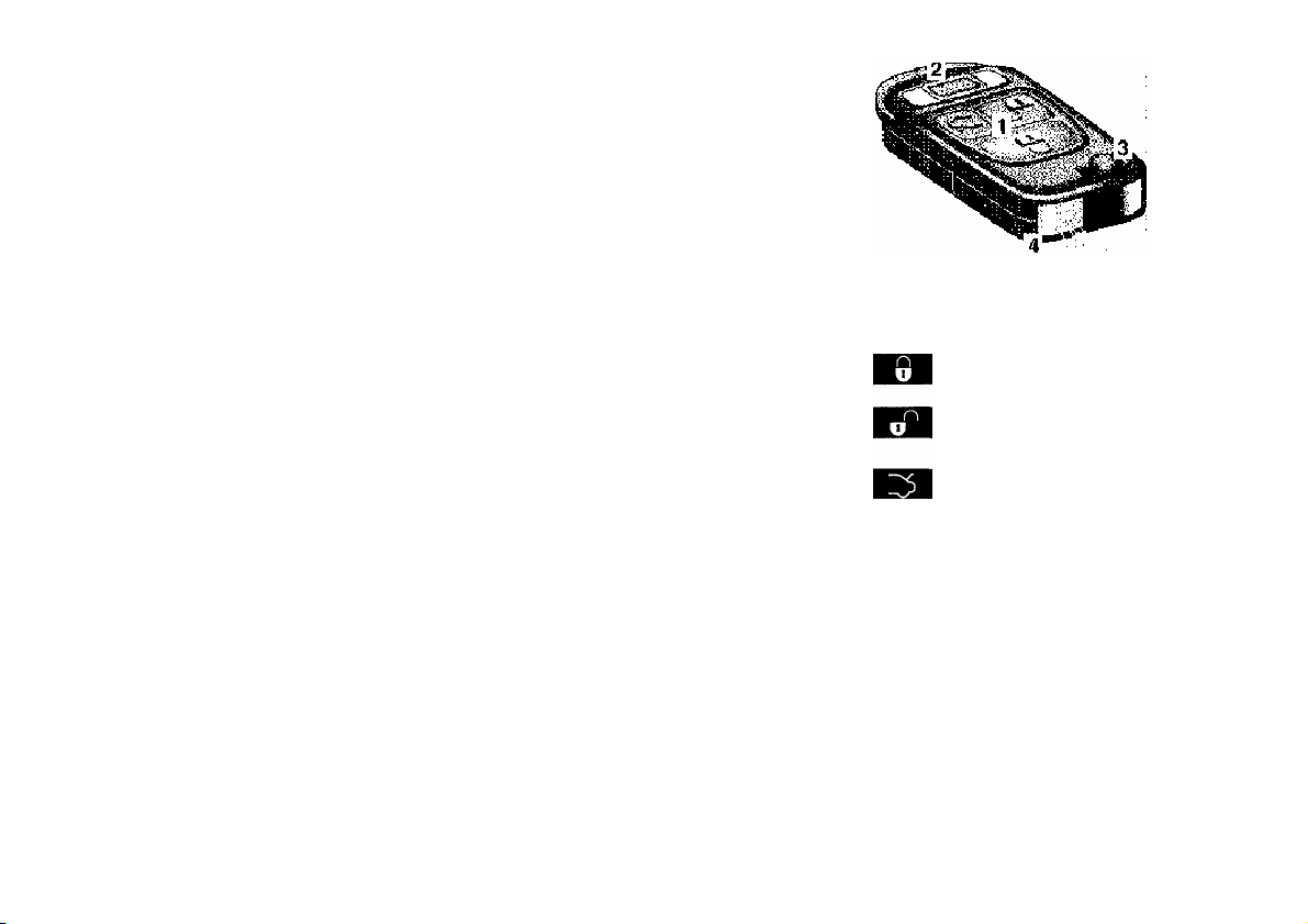
1 Transmit button
Locking
Unlocking
Opening trunk
(if not key locked)
2 PANIC button
3 Key release button
4 Lamp for battery check
and transmitter eye
29
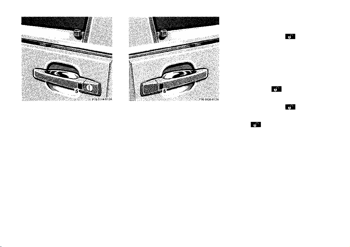
Locking and Unlocking
5 Infrared receiver in driver's door
handle
6 Infrared receiver in front
passenger door handle
Unlocking:
Press transmit button
signal lamps blink once to indicate that
the vehicle is unlocked.
The remote control can be programmed
for two kinds of unlocking methods
(see below):
Selective unlocking mode - Press
transmit button
driver's door and fuel filler flap.
Press transmit button
unlock doors, fuel filler flap, and trunk.
Global unlocking mode-Press transmit
button
filler flap, and trunk.
Notes:
If the trunk was previously locked
separately, it will remain locked (see
Index).
The presently active unlocking mode
(selective or global) can only be
determined by unlocking the vehicle
with the remote control (see below for
changing mode).
once to unlock doors, fuel
. All turn
once to unlock
twice to
30

The vehicle is automatically locked
again, if within 40 seconds of
unlocking with the remote control,
neither door or trunk is opened, the
key is not inserted in the steering lock,
or the central locking switch is not
activated.
Locking:
Press transmit button
turn signal lamps blink three times to
indicate that the vehicle is locked.
Note:
If the vehicle cannot be locked or
unlocked by pressing the transmit
button, then it may be necessary to
change the batteries in the transmitter
(if ok, battery check lamp in transmitter
will light briefly when transmitting) or
to synchronize the system, see Remote
Control in Index.
once. All
For operation in the USA only: This
devise complies with Part 15 of the
FCC Rules. Operation is subject to the
following two conditions:
(1) This device may not cause
harmful interference, and
(2) this device must accept any
interference received, including
interference that may cause
undesired operation.
Any unauthorized modification to this
device could void the user's authority
to operate the equipment
Choosing Global or Selective Mode
on Remote Control
Press and hold transmit buttons
and simultaneously for five
seconds to reprogram the remote
control. Battery check lamp will blink
two times indicating the completed
mode change.
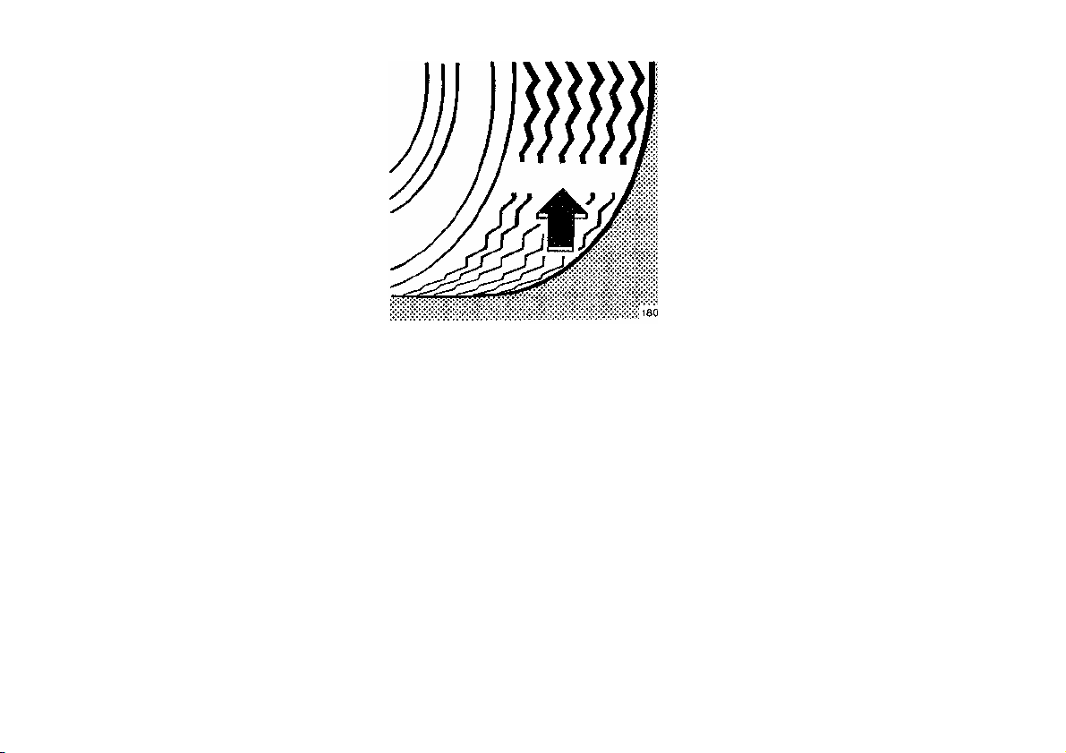
Opening the Trunk
A minimum height clearance of 5.9 ft.
(1.8 m) is required to open the trunk
lid.
Press transmit button
lid is released.
Important!
Do not place remote control in trunk
since trunk is locked again when
closing the lid.
Note:
If the trunk was previously locked
separately, it will remain locked
(see Index).
until trunk
31

Opening and Closing Windows and
Sliding/Pop-Up Roof from Outside
Aim transmitter eye (4) of remote
control at door receivers (5 or 6).
To open:
Continue to press transmit button
after unlocking car.
The windows and sliding/pop-up roof
begin to open after approx. 1 second.
To interrupt opening procedure,
release button.
To close:
Continue to press transmit button
after locking car.
The windows and sliding/pop-up roof
begin to close after approx. 1 second.
To interrupt closing procedure, release
button.
Warning!
Never operate the windows or
sliding/pop-up roof if there is the
possibility of anyone being harmed
by the opening or closing procedure.
In case the procedure causes
potential danger, the procedure can
be immediately halted by releasing
the remote control button. To
reverse direction of movement press
for opening or for closing.
The sliding/pop-up roof will only
open if it was not fully closed.
Note:
If the windows and sliding/pop-up roof
cannot be operated automatically by
pressing the transmit button of the
remote control then it may be
necessary to change the batteries in the
transmitter (if ok, battery check lamp
in transmitter will light briefly when
transmitting), or to synchronize the
system, see Remote Control, in Index.
Panic Button
To activate press and hold button (1)
for at least one second. The alarm will
last for approximately 3 minutes in
form of blinking exterior lamps, and
an additional horn will sound
intermittently.
To deactivate press button (1) again, or
turn key in steering lock to position 2.
32

Doors
The entire vehicle may be locked or
unlocked by either using the master
key in the door or trunk locks, or
central locking switch located in center
console. The central locking system
also locks or unlocks the fuel filler flap.
Note:
If the fuel filler flap cannot be opened,
refer to Fuel Filler Flap, Manual
Release (see Index).
1 Opening - pull handle
2 Unlocking
3 Locking
4 Individual door from inside:
• Push lock button down to lock.
• Pull lock button up to unlock.
When you lock the car, all door lock
buttons should move down. If any one
stays up, the respective door is not
properly closed.
You should then unlock the car, open
and reclose this door, and lock the car
again. Each individual door can be
locked with door lock button - the
driver's door can only be locked when
it is closed.
If the car has previously been locked
from the outside, only the door being
opened from the inside will unlock, and
the alarm will come on. The remaining
doors, the trunk lid and fuel filler flap
remain locked.
Note:
In case of a malfunction in the central
locking system the doors can be locked
and unlocked individually.
33
Central locking switch
1 Locking
2 Unlocking
The central locking switch is located in
the center console.
The doors and trunk can only be locked
with the central locking switch, if the
front doors are closed.
If the car was previously locked with
the remote control or key, the doors
and trunk cannot be unlocked with the
central locking switch.
If the car was previously locked with
the central locking switch, while in the
selective remote control mode, only the
door opened from the inside is
unlocked.
If the car was previously locked with
the central locking switch, while in the
global remote control mode, the
complete vehicle is unlocked when a
front door is opened from the inside.
Automatic Central Locking
The central locking switch also
operates the automatic central locking.
To activate:
With key in steering lock position 2
hold upper portion of switch (1) for a
minimum of 5 seconds.
To deactivate:
With key in steering lock position 2
hold lower portion of switch (2) for a
minimum of 5 seconds.
With the automatic central locking
system activated, the doors and trunk
are locked at vehicle speeds of approx.
9 mph (15 km/h) or more. The fuel
filler flap remains unlocked.
Notes:
If doors are unlocked with the central
locking switch after activating the
automatic central locking, and neither
door is opened, then the doors remain
unlocked even at vehicle speeds of
approx. 9 mph (15 km/h) or more.
Opening a door from the inside at
speeds of approx. 9 mph (15 km/h) or
less with the automatic central locking
activated, the door will again be
automatically locked at speeds of
approx. 9 mph (15 km/h) or more.
Emergency Unlocking in Case of
Accident
The doors unlock automatically a short
time after an accident (this is intended
to aid rescue and exit). However, the
key must still be in steering lock
position 2.
34

Notes:
In case of a malfunction in the central
locking system the doors and trunk can
be locked and unlocked individually.
If the fuel filler flap cannot be opened,
refer to Fuel Filler Flap, Manual
Release (see Index).
Trunk
0 Neutral position - push to open
1 Unlocking
2 Locking (detent)
3 Separate locking of trunk -
remove key in this position.
When the trunk is separately locked, it
remains locked when unlocking any
door.
To deny any unauthorized person
access to the trunk, lock it separately.
Leave only the valet key with the
vehicle.
The trunk lid can be lowered by using the
recessed grips in the trunk lid liner, and
closed with the dirt-free retracting handle.
If the trunk lid cannot be closed, refer to
Trunk Lid, Manual Closing (see Index).
35

Power Windows and Sliding/
Pop-Up Roof
1 Closing
2 Interrupting
3 Opening
When locking doors or trunk, turn key
in door lock or trunk lock to position
3 and hold. The windows and the
sliding/pop-up roof begin to close
automatically after approximately 2
seconds.
To interrupt the closing procedure, turn
key to position 2.
When unlocking doors or trunk, turn
key in door lock or trunk lock to
position 1 and hold. The windows and
the sliding/pop-up roof begin to open
automatically after approximately 1
second.
To interrupt the opening procedure,
turn key to position 2.
Warning!
Never operate the windows or
sliding/pop-up roof if there is the
possiblity of anyone being harmed
by the procedure.
In case the procedure causes
potential danger, the procedure can
be immediately reversed by turning
the key to the reversed operational
direction within 10 seconds:
• for opening position (1)
• for closing position (3).
The sliding/pop-up roof will only
open if it was not fully closed.
Note:
If the opening/closing procedure is
interrupted, it can only be continued
by first turning the key to the
interrupting position (2) and then
again to the opening/closing position
(1 or 3) and hold.
36

Power Closing Assist for Doors and
Trunk Lid
The doors and trunk lid close
automatically if:
• doors are pushed against the lock,
• trunk lid is lowered against the lock.
It is not necessary to slam doors or
trunk lid closed, a pneumatic powerassisted mechanism will latch doors
and trunk lid quietly and automatically
once the lid or door has been brought to
a close. When the pneumatic powerassisted mechanism has stopped, doors
and/or trunk can be reopened.
Note:
If the trunk lid does not close, refer to
Trunk Lid, Manual Closing in Index.
Warning!
To prevent possible personal injury,
always keep hands and fingers away
from the door or trunk opening
when closing a door or the trunk lid.
Be especially careful when small
children are around.
The pneumatic power closing assist
mechanism cannot be interrupted
once it has been engaged.
To prevent personal injury, never
activate the closing assist mechanism
by tampering with the door or trunk
lid latch.
37

1 Indicator lamp in switch located in
center console
Anti-Theft Alarm System
The anti-theft alarm is automatically
armed or disarmed with any of your
vehicle's keys or infrared remote
control by locking or unlocking either
front door or the trunk.
A blinking lamp (1) indicates that the
alarm is armed.
Operation:
Once the alarm system has been
armed, the exterior vehicle lamps will
flash and the horn will sound
intermittently when someone:
• opens a door,
• opens the trunk,
• opens the hood,
• switches on or bridges the
ignition circuit,
• steps on the brake pedal.
The alarm will last approximately
150 seconds in the form of blinking
exterior lamps. At the same time an
alarm horn will sound intermittently
for 60 seconds, pause for 30 seconds,
and repeat for another 60 seconds. The
alarm will stay on even if the activating
element (a door, for example) is
immediately closed.
Note:
We recommend that you carry the flat
key safely with you so that it is always
handy. The flat key has the same
functions as the master key.
38

Power Seats, Front
Warning!
Do not adjust the driver's seat while
driving. Adjusting the seat while
driving could cause the driver to lose
control of the vehicle.
Turn key in steering lock to position 1
or 2 (with the driver's or front
passenger's door open, the power
seats can also be operated with the
key removed or in steering lock
position 0).
Seat and head restraint adjustment:
Never ride in a moving vehicle with
the seat back reclined. Sitting in an
excessively reclined position can be
dangerous. You could slide under the
seat belt in a collision. If you side
under it, the belt would apply force
at the abdomen or neck. That could
cause serious or even fatal injuries.
The seat back and seat belts provide
the best restraint when the wearer is
in an upright position and belts are
properly positioned on the body.
Never place hands under seat or near
any moving parts while a seat is
being adjusted.
The slide switches are located in each
front door.
Warning!
When leaving the vehicle always
remove the key from the steering
lock.
The power seats can also be
operated with the driver's or front
passenger door open. Do not leave
children unattended in the vehicle.
Unsupervised use of vehicle
equipment may cause serious
personal injury.
A Seat, fore/aft, up/down
B Seat tilt
C Seat cushion depth
D Backrest tilt
E Head restraint Adjust head restraint
to support the back of the head
approximately at ear level. The head
restraint inclination can also be
adjusted manually.
Note:
Your car is equipped with power
head restraints, do not try to raise
or lower them manually.
39

Storing seat/head restraint/ steering
wheel and exterior rear view mirror
positions in memory:
Recalling seat/head restraint/ steering
wheel and exterior rear view mirror
positions stored in memory:
F Memory button
G Position buttons
Three sets of seat/head restraint/
steering wheel and exterior rear view
mirror positions may be programmed
into memory. After the seat/head
restraint/steering wheel and exterior
rear view mirrors are positioned, push
memory button F, release, and within 3
seconds push position button "1". A
second and third set of positions for the
same seat/ head restraint/steering wheel
and exterior rear view mirrors can be
programmed into memory by pushing
first button "F" and then "2",
respectively "3".
Note:
See Index for instructions on
adjustment of steering wheel and
mirrors.
To recall a seat/head restraint/ steering
wheel and exterior rear view mirror
position, push and hold position button
"1", "2" or "3" until seat/head
restraint/steering wheel/ and exterior
rear view mirror movement has
stopped. The seat/head
restraint/steering wheel and exterior
rear view mirror movement stops when
the position button is released.
Caution!
Do not remove head restraints except
when mounting seat covers. For
removal and installation refer to Head
Restraints, Removal in Index.
Whenever restraints have been
removed be sure to reinstall them
before driving.
40

Important!
Bring seat backrest to upright position
before recalling a stored seat/head
restraint/steering wheel and exterior
rear view mirror position, otherwise the
front seats could get forced against a
rear seat and be damaged.
Prior to operating the vehicle, the driver
should adjust the seat height for proper
vision as well as fore/aft placement and
seat back angle to insure adequate
control, reach, operation, and comfort.
The head restraint should also be
adjusted for proper height. See also
airbag section for proper seat
positioning.
Both the inside and outside rear view
mirrors should be adjusted for adequate
rearward vision.
Fasten seat belts. Infants and small
children should be seated in a properly
secured restraint system that complies
with U.S. Federal Motor Vehicle Safety
Standard 213 and Canadian Motor
Vehicle Safety Standard 213.1.
All seat, head restraint, and rear view
mirror adjustments as well as fastening
of seat belts should be done before the
vehicle is put into motion.
Warning!
Children 12 years old and under must
never ride in the front seat, except in
a Mercedes-Benz authorized
BabySmart™ compatible child seat,
which operates with the BabySmart™
system installed in the vehicle to
deactivate the passenger side front
airbag when it is properly installed.
Otherwise they will be struck by the
airbag when it inflates in a crash. If
this happens, serious or fatal injury
will result.
The back seat is the safest place for
children. Infants and small children
must ride in the back seats and be
seated in an infant or child restraint
system, which is properly secured
with the vehicle's seat belt, fully in
accordance with the seat
manufacturer's instructions.
A child’s risk of serious or fatal
injuries is significantly increased if
the child restraints are not properly
secured in the vehicle and they are
not properly secured in the child
restraint.
41

and side support.
The amount of cushion height and
curvature may be adjusted after turning
the key in steering lock to position 2.
The center section (2) can be selected
together with bottom section (1) or top
section (3).
The inflation pressure of the air cushion
can be continuously varied between
position "0" = without pressure, and
position "5" = maximum pressure, by
changing the pressure regulator (4)
setting.
Lumbar Support
1 Pressure regulator
The seats have an inflatable air
cushion built into the backrest to
provide additional lumbar support.
The inflation pressure of the air
cushion can be continuously varied
between position "0" = without
pressure, and position "5" = maximum
pressure, by changing the pressure
regulator (1) setting.
Multicontour Backrest
1 Bottom
2 Center
3 Top
4 Pressure regulator
5 Side bolster adjustment
Some models may be equipped with
multicontour seats. These seats have
inflatable air cushions built into the
backrest to provide additional lumbar
The side bolsters of the backrest can be
adjusted with push button (5):
• pushing forward increase side support,
• pushing backward -decrease
side support.
If the engine is turned off, the last
cushion setting is retained in memory,
and automatically adjusts the cushion to
this setting when the engine is
restarted.
42
Raise armrest to desired position.
Caution!
Keep compartment lids closed. This
will prevent stored objects from being
thrown about and injuring vehicle
occupants during an accident.
Keep cup holder closed while
traveling. Place only containers that fit
into the cup holder to prevent spills.
Do not fill containers to a height where
the contents could spill during vehicle
maneuvers, especially hot liquids.
Armrest with Compartments for
Cup Holder and Telephone
Handset (Front Seats)
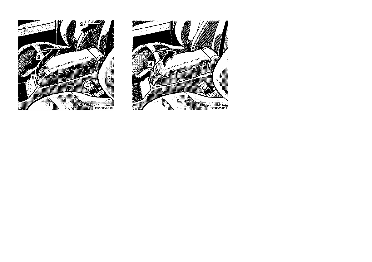
1 Armrest folded down
2 Normal use
(3 comfort positions)
3 Armrest folded up
Folding down:
Raise armrest past top comfort
position and push down.
Adjusting height:
Telephone Handset
Press button (4) to open cover.
Cup Holder
Press button (5) to open cup holder.
To close cup holder, push button (6)
down until cup holder engages.
Close cover.
Warning!
The armrest does not suffice as a
child restraint system. In case of a
frontal collision a child can be
catapulted forward over the locked
armrest. Infants and small children
should always be seated in a
properly secured restraint system
that complies with U.S. Federal
Motor Vehicle Safety Standard 213
and Canadian Motor Vehicle Safety
Standard 213.1.
43

Heated Seats
The front seat heaters can be switched
minutes of operation.
Note:
The front seat heater switches are
located to the left and right side of the
center console ashtray.
The rear seat heater switches are
located in each rear door.
on with the key in steering lock
positions 1 or 2, the rear seat heaters
only in steering lock position 2.
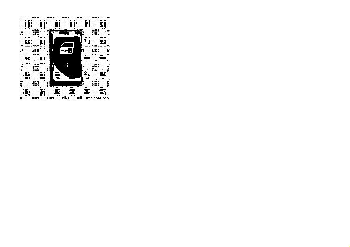
Press switch to turn on heater:
1 Normal heating mode. One
indicator lamp in the switch
lights up.
2 Rapid heating mode. Both
indicator lamps in the switch
light up.
After approximately 5 minutes in
the rapid heating mode, the heater
automatically switches to normal
operation and only one indicator
lamp will stay on.
Turning off heater:
If one indicator lamp is on, press
upper half of switch.
If both indicator lamps are on, press
lower half of switch.
If left on, the heater automatically
turns off after approximately 30
When in operation, the seat heater
consumes a large amount of power. It
is advisable not to use the seat heater
longer than necessary.
The seat heaters may automatically
switch off if too many power
consumers are switched on at the same
time, or if the battery charge is low.
When this occurs, the indicator lamp in
the switch will blink (both indicator
lamps blink during rapid seat heating).
The seat heaters will switch on again
automatically as soon as sufficient
voltage is available.
If the blinking of the indicator lamps is
distracting to you, the seat heaters can
be switched off.
44

Power Seats, Rear
The seats can be adjusted using the
slide switches located in either of the
rear doors.
Turn key in steering lock to position 1
or 2 (with the driver's or front
passenger's door open, the power seats
can also be operated with the key
removed or in steering lock position 0).
Seat Bench
1 Backrest tilt
Individual Seats
1 Backrest tilt
The seat cushion moves fore/aft
together with the inclination of the
backrest.
2 Seat tilt
45

.
restraints.
Armrest with Integrated
Compartment (Rear Bench Seat)
Pull down the armrest by its strap.
Before storing the armrest in the
backrest, close its storage compartment lid.
For the removal of the Rear Seat
Cushion, see Index.
Power Head Restraints, Rear
(Vehicles without rear power seats)
Turn key in steering lock to position
1 or 2.
Press symbol-side of rocker switch to
release the head restraints. The head
restraints will then fold back ward for
increased visibility.
Placing head restraints upright:
Pull head restraint forward by its strap
until it locks in position.
Inclination of head restraints:
The head restraint inclination can be
adjusted manually.
Important!
For safety reasons, always drive with
the rear head restraints in the upright
position when the rear seats are
occupied.
Keep area around head restraints clear
of articles (e.g. clothing) to not obstruct
the folding operation of the head
46

Switch on center console
2
Fold head restraint backward.
Power Head Restraints, Rear
(Vehicles with rear power seats)
Turn key in steering lock to position 1
or 2 (with the driver's or front
passenger's door open, the power head
restraints can also be operated with the
key removed or in steering lock
position 0).
Activate switch:
1 Place head restraint upright.
Switches in rear doors
Switch in center console:
Both head restraints together can be
placed in either upright or fold-down
position.
Switches in rear doors:
The head restraints can be placed
individually in either upright or folddown position.
Angle of head restraints:
The head restraint angle can be
adjusted manually.
Important!
For safety reasons, always drive with
the rear head restraints in the upright
position when the rear seats are
occupied.
Keep area around head restraints clear
of articles (e.g. clothing) to not obstruct
the folding operation of the head
restraints.
47

Adjustable Steering Wheel
Turn key in steering lock to position 1
Note:
or 2 (with the driver's or front
passenger's door open, the steering
wheel can also be operated with the
key removed or in steering lock
position 0).
To lengthen or shorten the steering
column, push in or pull out switch (1).
To raise or lower steering wheel, push
switch (1) up or down.
The steering wheel position can be
stored in memory together with the
seat/head restraint/exterior and inside
rear view mirror positions, see Index.
Warning!
Do not adjust the steering wheel
while driving. Adjusting the steering
wheel while driving could cause the
driver to lose control of the vehicle.
48

Seat Belts and Supplemental
for all seats, emergency ten™ tensioning
passengers we strongly recommend their
Restraint System (SRS)
Your vehicle is equipped with seat belts
retractors for the front seats, as well as
front and side impact airbags, and knee
bolsters for driver and front passenger.
Seat Belts
Important!
Laws in most states and all Canadian
provinces require seat belt use.
All states and provinces require use of
child restraints that comply with U.S.
Federal Motor Vehicle Safety Standard
213 and Canadian Motor Vehicle
Safety Standard 213.1.
For your safety and that of your
Warning!
Children 12 years old and under
must never ride in the front seat,
except in a Mercedes-Benz
authorized BabySmart™ compatible
child seat, which operates with the
BabySmart™ system installed in the
vehicle to deactivate the passenger
side front airbag when it is properly
installed. Otherwise they will be
struck by the airbag when it inflates
in a crash. If this happens, serious or
fatal injury will result.
The back seat is the safest place for
children. Infants and small children
must ride in back seats and be seated
in an infant or child restraint system,
which is properly secured with the
vehicle's seat belt, fully in accordance
with the seat manufacturer's
instructions.
Warning!
Never ride in a moving vehicle with
the seat back reclined. Sitting in an
excessively reclined position can be
dangerous. You could slide under the
seat belt in a collision. If you slide
under it, the belt would apply force
at the abdomen or neck. That could
cause serious or even fatal injuries.
The seat back and seat belts provide
the best restraint when the wearer is
in an upright position and belts are
properly positioned on the body.
use.
A child’s risk of serious or fatal
injuries is significantly increased if
the child restraints are not properly
secured in the vehicle and they are
not properly secured in the child
restraint.
49

Seat Belt Warning System
With the key in steering lock position
2, a warning sounds for a short time if
the driver's seat belt is not fastened.
Warning!
Failure to wear and properly fasten
and position your seat belt greatly
increases your risk of injuries and their
likely severity in an accident. You and
your passengers should always wear
seat belts.
If you are ever in an accident, your
injuries can be considerably more
severe without your seat belt properly
buckled. Without your seat belt buckled, you are much more likely to hit the
interior of the vehicle or be ejected
from it. You can be seriously injured
or killed.
In the same crash, the possibility for
injury or death is lessened with your
seat belt buckled.
Fastening of Seat Belts
1 Latch plate
2 Buckle
3 Release button
Push latch plate (1) into buckle (2)
until it clicks.
The lap belt should be positioned as
low as possible on your hips and not
across the abdomen.
Three-point seat belt:
Tighten the lap portion to a snug
fit by pulling shoulder portion up.
Rear center seat belt: Tighten to a snug
fit by feeding belt toward retractor.
Adjust seat belt so that shoulder
portion is located as close as possible
to the middle of your shoulder. Do not
twist the belt. A twisted seat belt may
cause injury.
The shoulder portion of the seat belt
must be pulled snug and checked for
snugness immediately after engaging
it. The height setting for the shoulder
portion of the front seat belts are
automatically adjusted by the fore/ aft
movement of the front seat.
Seat moved to front: Belt outlet fully
lowered.
Seat moved to rear: Belt outlet fully
raised.
50

Caution!
For safety reasons, avoid adjusting the
belt.
USE SEAT BELTS PROPERLY.
apply too much force to the
pre
ssure
on the abdomen.
seat or seat back into positions which
could affect the correct seat belt
position.
Unfastening of Seat Belts
Push the release button (3) in the belt
buckle (2).
Allow the retractor to completely
rewind the seat belt by guiding the
latch plate (1).
Notes:
The rear seat belt buckles can be stored
in the space next to the rear armrest (to
the left and right of armrest). The rear
center seat belt should be latched and
stored under the armrest.
For cleaning and care of the seat belts,
see Cleaning and Care of the Vehicle
in Index.
Operation:
The inertia reel stops the belt from
unwinding during sudden vehicle stops
or when quickly pulling on the belt.
The locking function of the reel may be
checked by quickly pulling out the
Warning!
• Each occupant should wear their
seat belt at all times, because seat
belts help reduce the likelihood of
and potential severity of injuries
in accidents, including rollovers.
"SRS" (driver airbag, passenger
airbag), "ETR" (seat belt
emergency tensioning retractors),
and knee bolsters are designed
to enhance the protection offered
to properly belted occupants in
certain frontal impacts which
exceed preset deployment
thresholds.
• Improperly positioned seat belts
do not provide maximum
protection and may cause serious
injuries in case of an accident.
• Never wear the shoulder belt
under your arm, against your
neck or off your shoulder. In a
crash, your body would move
too far forward. That would
increase the chance of head and
neck injuries. The belt would also
ribs or abdomen, which could
severely injure internal
organs such as your liver or
spleen.
• Position the lap belt as low as
possible on your hips and not
across the abdomen. If the
belt is positioned across your
abdomen, it could cause
serious injuries in a crash.
• Each seat belt should never be
used for more than one person
at a time. Do not fasten a seat
belt around a person and
objects.
• Belts should not be worn
twisted. In a crash, you wouldn't
have the full width of the belt to
take impact forces. The twisted
belt against your body could
cause injuries.
• Pregnant women should also
use a lap-shoulder belt. The
lap belt portion should be
positioned as low as possible on
the hips to avoid any possible
51

Warning!
USE CHILD RESTRAINTS
PROPERLY.
Children 12 years old and under
must never ride in the front seat,
except in a Mercedes-Benz
authorized BabySmart™ compatible
child seat, which operates with the
BabySmart™ system installed in the
vehicle to deactivate the passenger
side front airbag when it is properly
installed. Otherwise they will be
struck by the airbag when it inflates
in a crash. If this happens, serious or
fatal injury will result.
The back seat is the safest place for
children. Infants and small children
must ride in back seats and be seated
in an appropriate infant or child
restraint system, which is properly
secured with the vehicle's seat belt,
fully in accordance with the seat
manufacturer's instructions.
A child's risk of serious or fatal
injuries is significantly increased if
the child restraints are not properly
secured in the vehicle and the child is
not properly secured in the child
restraint.
Children too big for child restraint
systems must ride in back seats
using regular seal belts. Position
shoulder belt across chest and
shoulder, not face or neck. A
booster seat may be necessary to
achieve proper belt positioning.
BabySmart™ Airbag
Deactivation System
Special child seats, designed for use
with the Mercedes-Benz system and
available at any authorized MercedesBenz dealer are required for use with
the BabySmart™ airbag deactivation
system.
With the special child seat properly
installed, the passenger front airbag
will not deploy. The
lamp located on the center console
will be illuminated, except with key
removed or in steering lock position
0. The system does not deactivate the
door mounted side impact airbag.
BabySmart™ is a trademark of
Siemens Automotive Corp.
indicator
Warning!
The BabySmart™ Airbag
Deactivation System will ONLY
work with a special seat designed to
operate with it. It will not work with
seats which are not BabySmart™
compatible. Never place anything
between seat cushion and child seat
(e.g. pillow), since it reduces the
effectiveness of the deactivation
system. Follow the manufacturer's
instructions for installation of special
child seats. The passenger front
airbag will not deploy only if the
indicator lamp remains illuminated.
Please be sure to check the indicator
every time you use the special system
child seat. Should the light go out
while the restraint is installed,
Please check installation. If the light
remains out, do not use the
BabySmart™ restraint to transport
children, or other wise - do not
transport child restraints on the
front passenger seat until the system
has been repaired.
52

Self-Test BabySmart™
Without Special Child Seat
installed
After turning key in steering lock to
position 1 or 2, the indicator
lamp located on center console comes
on for approx. 6 seconds.
If the lamp should not come on or is
continuously lit, the system is not
functioning. You must see an authorized
Mercedes-Benz dealer before using any
child seat.
BabySmart™ is a trademark of
Siemens Automotive Corp.
The SRS uses two crash severity levels
(thresholds) to activate either the ETR
or airbag or both. Activation depends
on the direction and severity of the
impact, exceeding the thresholds and
fastening of the seat belt.
Seat belt fastened
• first threshold exceeded:
ETR activates
• second threshold exceeded:
airbag also activates
Seat belt not fastened
• first threshold exceeded:
airbag activates, but not ETR
The emergency tensioning retractors are
designed to activate only when the seat
belts are fastened during frontal and
front-angled impacts exceeding the first
threshold of the SRS. They remove slack
from the belts in such a way that the seat
belts fit more snugly against the body
restricting its forward movement as
much as possible.
In cases of other frontal impacts, rollovers, certain side impacts, rear
collisions, or other accidents without
frontal forces, the emergency tensioning
retractors will not be activated. The
driver and passengers will then be
protected by the fastened seat belts and
inertia reel in the usual manner.
Supplemental Restraint System
(SRS)
The term Supplemental Restraint
System means that airbags are intended
as a supplement to seat belts. Airbags
alone cannot protect as well as airbags
plus seat belts in impacts for which the
airbags were designed to operate, and
do not afford any protection
whatsoever in crashes for which the
system is not designed to deploy.
Driver and front passenger systems
operate independently from each other.
Emergency Tensioning
Retractor (ETR)
The seat belts for the front seats are
equipped with emergency tensioning
retractors. These tensioning retractors
are located in each belt's inertia reel
and become operationally ready with
the key in steering lock position 1 or 2.
For seat belt and emergency tensioning
retractor safety guidelines see Safety
Guidelines in Index.
53

Airbags
1 Driver airbag
2 Front passenger airbag
3 Side impact airbag
The most effective occupant restraint
system yet developed for use in
production vehicles is the seat belt. In
some cases, however, the protective
effect of a seat belt can be further
enhanced by an airbag.
The driver airbag is located in the
steering wheel hub. The passenger
airbag is located in the dashboard
ahead of the passenger.
The side impact airbags are located in
the front doors. In conjunction with
wearing the seat belts with emergency
tensioning retractors, the airbags can
provide increased protection for the
driver and passenger in certain major
frontal and front-angled and side
impacts.
The operational readiness of the airbag
system is verified by the indicator
lamp "SRS" in the instrument cluster.
If no fault is detected, the lamp will go
out after approximately 4 seconds;
after the lamp goes out, the system
continues to monitor the components
and circuitry of the airbag system and
will indicate a malfunction by
coming on again.
The following system components are
monitored or undergo a self-check:
crash-sensor, airbag ignition circuits,
driver and passenger seat belt buckles.
Initially, when the key is turned from
steering lock position 0 to positions 1
or 2, malfunctions in the crash-sensor
are detected and indicated (the "SRS"
indicator lamp stays on longer than 4
seconds).
Initially, when the key is turned from
steering lock position 0 to positions 1 or
2, malfunctions in the crash-sensor are
detected and indicated (the "SRS"
indicator lamp stays on longer than 4
seconds). In the operational mode,
54

after the indicator lamp has gone out
following the initial check, interruptions and short circuits in the airbag
ignition circuit and in the driver and
passenger seat belt buckle harnesses,
and low voltage in the entire system are
detected and indicated.
Warning!
The passenger front airbag deploys
only if the passenger seat is occupied.
Note:
Heavy objects on passenger seat can
cause the front airbag to deploy in a
crash.
Side Impact Airbags
Only during these types of impacts,
if of sufficient severity to meet the
deployment thresholds, will they
provide their supplemental
protection. The driver and passenger
should always wear the seat belts,
otherwise it is not possible for the
airbags to provide their intended
supplemental protection.
In the event a malfunction of the
"SRS" is indicated as outlined above,
the "SRS" may not be operational.
For your safety, we strongly recommend that you visit an authorized
Mercedes-Benz dealer immediately
to have the system checked;
otherwise the "SRS" may not be
activated when needed in an
accident, which could result in
serious or fatal injury, or it might deploy unexpectedly and unneccesarily
which could also result in injury.
Front Airbags
The driver and passenger front "SRS"
airbags are designed to activate only in
certain frontal impacts.
The side impact "SRS" airbags are
designed to activate only in certain side
impacts. Only the side airbag on the
impacted side of the vehicle deploys.
The side impact airbag for the front
passenger deploys only if the seat is
occupied.
Side impact airbags operate best in
conjunction with a properly positioned
and fastened seat belt.
Note:
Heavy objects on passenger seat can
cause the side impact airbag to
deploy in a crash.
Important!
The "SRS" airbags are designed to
activate only in certain frontal or
side impacts.
In cases of other frontal impacts,
roll-overs, other side impacts, rear
collisions, or other accidents without
sufficient forces, the airbag will not
be activated. The driver and
passengers will then be protected by
the fastened seat belts.
We caution you not to rely on the
presence of an airbag in order to
avoid wearing your seat belt.
The "SRS" is designed to reduce the
potential of injury in certain frontal,
front-angled and side impacts which
may cause injuries, however, no
system available today can totally
eliminate injuries and fatalities.
55

The activation of the "SRS"
temporarily releases a small amount
of dust from the airbags.
This dust, however, is neither
injurious to your health, nor does it
indicate a fire in the vehicle.
The service life of the airbags
extends to the date indicated on the
label located on the driver-side door
latch post. To provide continued
reliability after that date, they should
be inspected by an authorized
Mercedes-Benz dealer at that time
and replaced when necessary.
Warning!
It is very important for your
safety to always be in a properly
seated position and to wear your seat
belt.
For maximum protection in the event
of a collision always be in normal
seated position with your back
against the seat back. Fasten your
seat belt and ensure that it is
properly positioned on the body.
Since the airbag inflates with
considerable speed and force, a
proper seating and hands on steering
wheel position will help to keep you
in a safe distance from the airbag:
• Sit properly belted in an upright
position with your back against
the seat back.
• Adjust the driver seat as far as
possible rearward, still
permitting proper operation of
vehicle controls.
• Do not lean with your head or
chest close to the steering wheel
or dashboard.
• Keep hands on the outside of
steering wheel rim. Placing
hands and arms inside the rim
can increase
the risk and potential severity of
hand/arm injury when airbag
inflates.
• Adjust the front passenger seat
rearward as far as possible from
the dashboard when the seat is
occupied.
• Children 12 years old and under
must never ride in the front seat,
except in a Mercedes-Benz
authorized BabySmart™
compatible child seat, which
operates with the BabySmart™
system installed in the vehicle to
deactivate the passenger side
front airbag when it is properly
installed. Otherwise they will be
struck by the airbag when it
inflates in a crash. If this
happens, serious or fatal injury
will result.
Failure to follow these instructions
can result in severe injuries to you or
other occupants.
56

Safety Guidelines for the Seat Belt,
within the steering wheel gets
Emergency Tensioning Retractor
and Airbag
Warning!
• Damaged belts or belts that
were highly stressed in an
accident must be replaced
and their anchoring points
must also be checked. Use only
belts installed or supplied by
an authorized Mercedes-Benz
dealer.
• Do not pass belts over sharp
edges.
• Do not make any modification
that could change the
effectiveness of the belts.
• The "SRS" is designed to
function on a one-time-only
basis. An airbag or emergency
tensioning retractor (ETR) that
was activated must be replaced.
• No modifications of any kind
may be made to any
components or wiring of the
"SRS". This includes the
installation of additional trim
material, badges etc. over the
steering wheel hub or front
passenger airbag cover and
installation of additional
electrical/electronic equipment
on or near "SRS" components
and wiring.
• An airbag system component
hot after the airbag has inflated.
• Improper work on the system,
including incorrect installation
and removal, can lead to
possible injury through an
uncontrolled
activation of the "SRS".
• In addition, through improper
work there is the risk of
rendering the "SRS"
inoperative. Work on the
"SRS" must therefore only be
performed by an authorized
Mercedes-Benz dealer.
• When scrapping the airbag
unit or emergency tensioning
retractor, it is mandatory
to follow our safety instruct
ions. These instructions are
available at your authorized
Mercedes-Benz dealer.
When you sell the vehicle we strongly
urge you to give notice to the subsequent
owner that it is equipped with an "SRS"
by alerting him to the applicable section
in the Owner's Manual.
Infant and Child Restraint
Systems
We recommend that all infants and
children be properly restrained at all
times while the vehicle is in motion.
All lap-shoulder belts except driver seat
have special seat belt retractors for
secure fastening of child restraints. To
fasten a child restraint, use this seat
belt: Follow child restraint instructions
for routing. Then pull shoulder belt out
completely and let it retract. The belt is
now locked. Push down on child
restraint to take up any slack.
57

Important!
ride in the front seat, except in a
The use of infant or child restraints is
required by law in all 50 states and all
Canadian provinces.
Infants and small children should be
seated in an infant or child restraint
system properly secured by a lap
shoulder belt, and that complies with
U.S. Federal Motor Vehicle Safety
Standard 213 and Canadian Motor
Vehicle Safety Standard 213.1. A
statement by the child restraint
manufacturer of compliance with this
standard can be found on the
instruction label on the restraint and in
the instruction manual provided with
the restraint.
When using any infant or child restraint
system, be sure to carefully read and
follow all manufacturer's instructions
for installation and use.
Please read and observe warning labels
affixed to inside of vehicle.
Warning!
Children 12 years old and under must
never
Mercedes-Benz authorized
BabySmart™ compatible child seat,
which operates with the
BabySmart™ system installed in the
vehicle to deactivate the passenger
side front airbag when it is properly
installed. Otherwise they will be
struck by the airbag when it inflates
in a crash. If this happens, serious or
fatal injury will result.
The back seat is the safest place for
children. Infants and small children
must ride in back seats and be seated
in an infant or child restraint system,
which is properly secured with the
vehicle's seat belt, fully in accordance
with the seat manufacturer's
instructions.
Infants and small children should
never share a seat belt with another
occupant. During an accident, they
could be crushed between the
occupant and seat belt.
Children too big for child restraint
systems must ride in back seats using
regular seat belts. Position shoulder
belt across chest and shoulder, not
face or neck. A booster seat is
necessary to achieve proper belt
positioning for children from 41 Ibs.
to the point where a lap/shoulder belt
fits properly without one.
When the child restraint is not in use,
remove it from the car or secure it
with the seat belt to prevent the child
restraint from becoming a projectile
in the event of an accident.
U.S.A. Models only: Since 1986 all
U.S. child restraints comply with U.S.
regulations without the use of a tether
strap.
Canada Models only:
This vehicle is provided with tether
anchorages for a top tether strap.
Consult your authorized MercedesBenz dealer for installation of these
anchorages.
In compliance with Canadian Motor
Vehicle Safety Standard 210.1, child
restraint tether anchorage hardware is
attached to the tool kit located in the
trunk.
58

1 Steering is unlocked.
(If necessary, move steering wheel
slightly to allow the key to be turned
clockwise to position 1.)
Most electrical consumers can be
operated. For detailed information
see respective subjects.
2 Driving position.
Notes:
A warning sounds when the driver's
door is opened with the key in steering
lock position 1 or 0.
With the engine at idle speed, the
charging rate of the alternator (output)
is limited.
Steering Lock
0 The key can be withdrawn in this
position only. The steering is
locked with the key removed
from the steering lock. The key
can be removed only with the
selector lever in position "P".
After removing the key or with
the key in steering lock position 0,
the selector lever is locked in
position "P".
3 Starting position.
Refer to Index for Starting and turning
off the engine.
Warning!
When leaving the vehicle always
remove the key from the steering
lock. Do not leave children
unattended in the vehicle.
Unsupervised use of vehicle
equipment may cause serious
personal injury.
It is therefore recommended to turn off
unnecessary electrical consumers while
driving in stop-and-go traffic. This
precaution helps to avoid draining of
the battery.
Unnecessary strain on the battery and
charging system may be minimized by
turning off the following power
consumers, for example: Heated seats,
rear window defroster. In addition, the
automatic climate air volume control
should be set to the lowest position.
Caution!
To prevent accelerated battery
discharge and a possible dead battery,
always remove the key from the
steering lock. Do not leave the key in
steering lock position 0.
59

Combination Switch
1. Low beam (exterior lamp
switch position )
2. High beam (exterior lamp
switch position )
3. High beam flasher (high beam
available independent of
exterior lamp switch position)
4. Turn signals, right
5. Turn signals, left
To signal minor directional changes,
such as changing lanes on a highway,
move combination switch to the point
of resistance only and hold it there.
To operate the turn signals
continuously, move the combination
switch past the point of resistance (up
or down). The switch is automatically
canceled when the steering wheel is
turned to a large enough degree.
6. Press switch briefly:
One wipe without washer water
(select only if window is wet)
Press switch past resistance point:
Windshield washer, windshield
wiper; headlamp cleaning system
(only in exterior lamp switch
positions or .
7. Windshield wiper
O Wiper off
I Intermittent wiping
One initial wipe, pauses
between wipes are
automatically controlled by a
rain sensor monitoring the
wetness of the windshield.
II Normal wiper speed
III Fast wiper speed
Note:
The windshield washer reservoir,
hoses and nozzles are automatically
heated.
Turn Signal Failure
If one of the turn signals fails, the turn
signal indicator system flashes and
sounds at a faster than normal rate.
60

Windshield Washer Fluid Mixing
Ratio
For temperatures above freezing:
MB Windshield Washer
Concentrate "S" and water
1 part "S" to 100 parts water (40
ml "S" to 1 gallon water).
For temperature below freezing:
MB Windshield Washer Concentrate
"S" and commercially available
premixed windshield washer
solvent/antifreeze
1 part "S" to 100 parts solvent (40 ml
"S" to 1 gallon solvent).
Windshield Wiper Smears
If the windshield wiper smears the
windshield, even during rain, activate
the washer system as often as
necessary. The fluid in the washer
reservoir should be mixed in the
correct ratio.
Blocked Windshield Wiper
If the windshield wiper becomes
blocked (for example, due to snow),
switch off the wiper motor.
For safety reasons before removing ice
or snow, remove key from steering
lock. Remove blockage.
Activate combination switch again
(key in steering lock position 1).
Emergency Operation of
Windshield Wiper
In case of windshield wiper malfunction in switch positions I or III,
turn combination switch to wiper
setting II.
Have the system checked at your
authorized MERCEDES-BENZ dealer
as soon as possible.
61

Exterior Lamp Switch
Rear fog lamp (pull out to 2nd
Off
Parking lamps (also side
marker lamps, taillamps,
license plate lamps,
instrument panel lamps)
Canada only: When the
engine is running, the low
beam is additionally switched
on.
Parking lamps plus low beam
or high beam headlamps
(combination switch pushed
forward)
Standing lamps, right
(turn left one stop)
Standing lamps, left
(turn left two stops)
Front fog lamps
(pull out one stop) with
parking lamps and/or low
beam headlamps on.
detent) in addition to fog
lamps. Yellow indicator lamp
in lamp switch comes on
Standing Lamps
When the vehicle is parked on the
street the standing lamps (right or left
side parking lamps) can be turned on,
making the vehicle more visible to
passing vehicles.
The standing lamps cannot be operated
with the electronic key in steering lock
position 2.
Note:
With the key removed and the driver's
door open, a warning sounds if the
vehicle's exterior lamps (except
standing lamps) are not switched off.
.
Fog lamps will operate with the
parking lamps and/or the low beam
headlamps on. Fog lamps should only
be used in conjunction with low beam
headlamps. Consult your State or
Province Motor Vehicle Regulations
regarding allowable lamp operation.
Fog lamps are automatically switched
off when the exterior lamp switch is
turned to position
Daytime Running Lamps
(Canada only)
When the engine is running and the
selector lever is in a driving position,
the low beam (includes parking lamps,
side marker lamps, taillamps and
license plate lamps) are automatically
switched on.
When shifting from a driving position
to position "N" or "P", the low beam
switches off (2 seconds delay).
For nighttime driving the exterior lamp
switch should be turned to position
to permit activation of the high
beam headlamps.
.
62
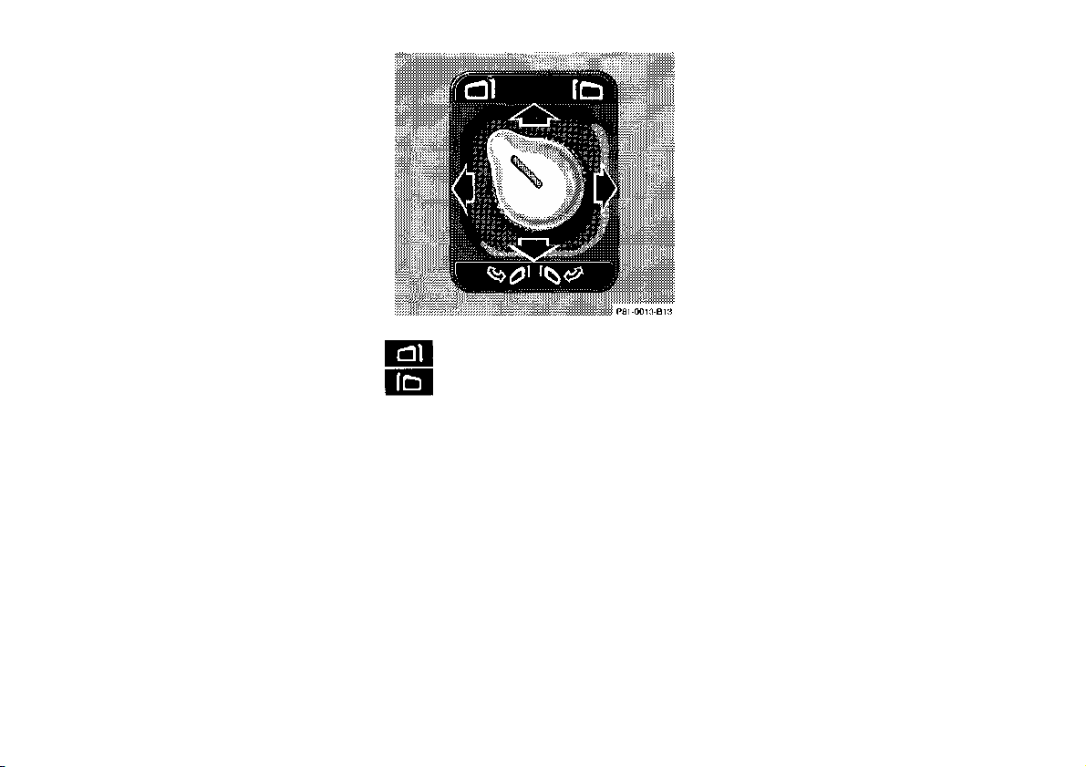
Night Security Illumination
When exiting the vehicle after driving
with the exterior lamps on, the
headlamps switch on for added security
for approximately 30 seconds after
closing the last door. The lamp-on time
period can be changed at your
Mercedes-Benz dealer.
reflection brightness responds to
changes in light sensitivity.
With gear selector lever in position
"R", or with the interior lamp switched
on, the mirror brightness does not
respond to changes in light sensitivity.
Note:
Inside Rear View Mirror
Manually adjust the mirror.
Use your inside mirror to deter-mine
the size and distance of objects seen in
the passenger convex mirror.
Antiglare Night Position
With the key in steering lock position
2, the mirror reflection brightness
responds to changes in light sensitivity.
With gear selector lever in position "R",
or with the interior lamp switched on,
the mirror brightness does not respond
to changes in light sensitivity.
Note:
The automatic antiglare function is
restricted, if incoming light is not
aimed directly at sensors in the
mirror.
Exterior rear view mirror, left
Exterior rear view mirror, right
Exterior Rear View Mirrors
Turn key in steering lock to position
2 (with either front door open, the
mirrors can be operated with key
removed or in steering lock
position 0 or 1).
Turn switch to select the mirror to be
adjusted.
To adjust, move the switch forward,
backward or to either side.
With the key in steering lock position
2, the driver's side mirror
The exterior mirrors have electrically
heated glass. The heater switches on
automatically, depending on outside
temperature.
If an exterior mirror housing is forcibly
pivoted from its normal position, it
must be repositioned by applying firm
pressure until it snaps into place.
Warning!
Exercise care when using the
passenger-side mirror. The
passenger-side exterior mirror is
convex (outwardly curved surface
for a wider field of view). Objects in
mirror are closer than they appear.
Check your inside rear view mirror
or glance over your shoulder before
changing lanes.
63

Exterior Rear View Mirror
Multiple Images
This vehicle is equipped with antifogging dual-pane side windows to
provide extra insulation against heat,
cold and noise. Because of the second
pane of glass, under certain light and
weather conditions a multiple image
may become noticable, especially when
looking through the side windows at an
outside rear view mirror.
Storing Mirror Positions in
Memory
The exterior and inside rear view
mirror positions are stored in memory
with the seat/head restraint/ steering
column position and can be recalled
when necessary, see Index.
Folding the mirrors out
Turn switch to point rearward. Press
switch forward until the mirrors are
folded out.
Important!
Do not fold mirrors out, forcing them
by hand. This will damage the
operating mechanism of the mirrors.
Folding the mirrors in
Turn switch to point rearward. Press
switch rearward until the mirrors are
folded in.
Important!
Before running the vehicle through an
automatic car wash, fold mirror in,
otherwise they may get damaged.
64

Sun Visors
Illuminated Vanity Mirrors
Roar seats:
Swing sun visors down to protect
against sun glare.
If sunlight enters through a side
window, disengage visor from inner
mounting and pivot to the side.
Front seats:
With the visor engaged in its inner
mounting, the lamp can be switched
on by opening the cover.
Warning!
Do not use the vanity mirror while
driving.
Touch the cover to lower the mirror.
The lamp will switch on automatically.
Close the cover and the lamp will go
out.
65

Interior Lighting
1 Interior Lamps (Door contact)
A B
A Interior lamps are switched on,
and off delayed, when unlocking
or locking the vehicle, or when
opening or closing either front
door. However, there will be no
delay when the key is in steering
lock position 2.
B Interior lamps switched off.
2 Interior Lamps
A B
A Interior lamps switched off.
B Interior lamps switched on,
3 Rear Courtesy Lamps
A B
A Courtesy lamps switched off.
B Courtesy lamps switched on.
Note:
The courtesy lamps cannot be
switched off as long as a rear door is
open.
2 Reading Lamps, Front
A
B
A Reading lamp switched off.
B Reading lamp switched on.
5 Reading Lamps, Rear
The lamps are switched on and off
individually with a switch in the
respective lamp.
Entrance Lamps, Exit Lamps
The lamps are switched on and off by
the door contact switches.
Note:
To prevent the vehicle battery from
being discharged, do not leave doors
open for a long period of time.
66

Storage Compartments
in the Dashboard
1 Storage/eyeglasses
compartment
Storage/Eyeglasses Compartment
To open: Press button (2).
Glove Box
Storage Compartments
Caution!
Keep compartment lids closed. This
will prevent stored objects from being
thrown about and injuring vehicle
occupants during an accident.
2 Button for storage/
eyeglasses compartment
3 Glove box
4 Button for glove box
5 Lock
The glove box lid is equipped with a
container for coins and small
accessories.
To open: Press button (4).
Note:
The storage compartments may be
locked and unlocked by using the
master key in lock (5).
Locking:
Turn master key in lock (5) to the
right and remove.
Unlocking:
Turn master key back to vertical
position.
67

Storage Compartment below the
Front Armrest
(Vehicles without rear passenger
compartment climate control)
Slide cover to
6 open,
7 close.
Storage Compartments in the Rear
Passenger Compartment
(Vehicles with individual seats)
Slide cover to
6 open,
7 close.
First Aid Kit
1 Opening lid
The first aid kit is stored in the shelf
below the rear window.
Stowing Things in the Vehicle
Warning!
To help avoid personal injury
during a collision or sudden
maneuver, exercise care when
stowing things. Put luggage or cargo
in the trunk if possible. Do not pile
luggage or cargo higher than the
seat backs. Do not place anything on
the shelf below the rear window.
68

in center console, front
in rear doors
Lighter
Ashtrays
By touching the top of the cover
lightly, the ashtray opens automatically.
Warning!
Remove front ashtray only with
vehicle standing still. With the gear
selector lever in position "N", turn
off the engine and set the parking
brake. Otherwise the vehicle might
move as a result of unintended
contact with the gear selector lever.
To remove ashtray from center
console:
Push sliding knob (1) toward the
right to eject the insert.
To remove ashtray from rear door:
Hold left and right side of insert and
pull up.
To install ashtray:
Install insert into ashtray frame
and push down to engage.
Turn key in steering lock to position
1 or 2.
Push in lighter (1); it will pop out
automatically when hot.
Warning!
Never touch the heating element or
sides of the lighter, hold at knob
only.
Note:
The lighter socket can be used to
accomodate electrical accessories up to
maximum 85 W.
69

Sliding/Pop-Up Roof (optional)
1 to slide roof open
2 to slide roof closed
3 to raise roof at rear
4 to lower roof at rear
Turn key in steering lock to position
1 or 2.
The switch is illuminated when the
exterior lamps are switched on (except
standing lamps).
With the roof closed or tilted open, a
screen can be slid into the roof opening
to guard against sun rays. When sliding
the roof open, the screen will also
retract.
Warning!
When closing the sliding roof, be
sure that there is no danger of
anyone being harmed by the closing
procedure.
Notes:
The sliding roof can be opened or
closed manually should an electrical
malfunction occur, refer to Emergency
Operation in Index.
The sliding roof can also be closed
with the key or infrared remote control
while locking the vehicle doors or
trunk (see Central Locking System in
Index).
70

in center console, front
Power Windows
Switches for:
1 left, front
2 left, rear
3 right, front
4 right, rear
5 Switch for rear door window
override
6 individual switches
(rear center doors)
in rear doors
Turn key in steering lock to
position 1 or 2.
Press switch in to resistance point:
to close
to open
Release switch when window is in
desired position.
Express Opening and Closing
Press switch or past resistance
point and release - window opens or
closes completely.
To interrupt procedure, briefly
press or .
If the upward movement of the
window is blocked during the closing
procedure, the window will stop during
the last few inches before closure and
open slightly.
When pressing and holding the switch
to close the window, and upward
movement of the window is blocked
during the last few inches before
closure, it will stop but not open
slightly.
Blocking of Rear Door Window
Operation
If no operation of the rear windows by
switch (6) (for instance by children) is
desired, slide safety switch (5) to right,
symbol becomes visible.
71

Warning!
When closing the windows, be sure
that there is no danger of anyone
being harmed by the closing
procedure.
In case of obstruction, the automatic
reversal will not operate if a window
is being closed by pressing the switch
to its resistance point and holding it
there, or when using a key or the
remote control.
The closing procedure can be
immediately reversed by either
pressing the switch , turning the
key to the unlocking position, or
releasing and pressing the transmit
button, and holding it.
The power windows can also be closed
with the key or infrared remote control
while locking the vehicle doors or
trunk (see Central Locking System in
Index).
Warning!
When leaving the vehicle,
always remove the key from
the steering lock. Do not leave
children unattended in the
vehicle. Unsupervised use of
vehicle equipment can cause
serious personal injury.
Synchronizing Power Windows
If the power supply was interrupted
(battery disconnected or empty), the
windows cannot be opened or closed
by the Express feature.
To resynchronize the Express feature,
press side of power window switch
until the window is completely closed
and hold for additional 2 seconds.
Repeat procedure for each window.
The automatic full opening and closing
procedure of the windows should now
be restored.
72

Rear Window Sunshade
Note:
The trunk lid cannot be released by
the switch when previously locked
with the key. To open, refer to Trunk,
separately locked (in Index).
Shelf below Rear Window
Warning!
The shelf below the rear window
should not be used to carry objects.
This will prevent such objects from
being thrown about and injuring
vehicle occupants during an accident
or sudden maneuver.
Trunk Lid Release Switch
1. Hold to raise
2. Hold to lower
The switches are located on the center
console and between the single rear
seats
The sunshade should always be either
fully raised or fully lowered
The switch is located in the center
console.
A minimum height clearance of 1.8 m
(5.9 ft) is required to open the trunk
lid.
To open the trunk, the vehicle must
be parked and unlocked. Press symbol
side of switch until trunk lid is open.
With vehicle centrally locked, the trunk
can also be opened by using the
infrared remote control. twice. Press
button .
73

Instrument Lamps
Rotate adjusting knob (1) to vary
intensity of instrument lamps.
Display Illumination
Press adjusting knob to briefly
illuminate the display (with key
removed or in steering lock
position 0 or 1).
With exterior lamps switched on
the display illumination becomes
automatically dim.
1 Adjusting knob
Rotate adjusting knob clockwise to
its stop to override the dimmed
illumination.
Trip odometer
To reset:
• Press adjusting knob (1) once
(with key in steering lock
position 2).
• Press adjusting knob (1) twice
(with key removed or in
steering lock position 0 or 1).
Clock
Adjusting clock one minute ahead or
back:
Pull out adjustment knob (2), briefly
turn to the right respectively left and
release knob.
Adjusting clock more than one minute
ahead or back: Pull out adjustment
knob (2), turn to the right respectively
left and hold until the desired time is
set. Within the first 2 seconds, the
minute hand advances 8 minutes and
advances another 8 minutes every
additional second thereafter
74

located on
Warning!
When programming a garage door
opener, the door moves up or down.
(2) this device must accept any
interference received, including
interference that may cause undesired
operation.
Garage Door Opener
1 Remote control transmitter
inside rear view mirror
2 Portable remote control transmitter
The built-in remote control is capable of
operating up to three separately
controlled objects.
When programming or operating the
remote control make sure there is no
possibility of anyone being harmed by
the moving door.
Notes:
Certain types of garage door openers
are incompatible with the integrated
opener. If you should experience
difficulties with programming the
transmitter, contact your authorized
Mercedes-Benz dealer or call
Mercedes-Benz Customer Assistance
Center (in the U.S.A. only) at 1-800FOR-MERCedes.
For operation in the USA only: This
devise complies with Part 15 of the
FCC Rules. Operation is subject to the
following two conditions:
(1) This device may not cause harmful
interference, and
Any unauthorized modification to this
device could void the user's authority
to operate the equipment.
Programming the remote control:
1. Turn key in steering lock to
position 1 or 2.
2. Press and hold one button of
the remote control located on
the inside rear view mirror until
its control light begins to flash at
a rate of about once a second.
Continue holding down the
button.
3. Hold end opposite to battery of
portable remote control against
the inside rear view mirror transmitter to be programmed. While
still holding down the button on
the transmitter on the inside rear
view mirror, press down the but
ton on your portable remote control,
until the inside rear view mirror
75

remote control light starts to flash, first
slowly, then rapidly. This means that
the integrated remote control has
accepted the frequency and code of the
portable transmitter.
4. If you wish to reprogram or program
the remaining buttons, repeat steps 1
and 3.
Note:
If the garage door opener is equipped
with the "rolling code feature", it needs
to be trained to accept the remote
control command.
To do so, the assistance of a
second person is required.
1. Locate training button (part of
the opener unit in the garage).
2. Press and hold training button
until training light next to the
button begins to flash (in two
seconds).
3. Now have the second person
press and hold the previously
programmed button on the
interior rear view mirror until the
training light on the garage door
opener is lit continuously (in two
seconds).
4. Release and press the programmed
button on the rear view mirror
once again to turn off the training
light in the garage door opener.
5. Confirm the garage door
operation by pressing the
programmed button on the
interior rear view mirror.
Operation of remote control:
1. Turn key in steering lock to
position 1 or 2.
2. Select and press the appropriate
button (1, 2 or 3) to activate the
remote controlled device. The
remote control transmitter
continues to send the signal as long
as the button is pressed - up to 20
seconds.
Erasing the remote control
memory:
1. Turn key in steering lock to
position 1 or 2.
2. Simultaneousy holding down the
left and right side buttons for
approximately 20 seconds, or
until the control light blinks
rapidly, will erase the codes of
all three channels.
Antenna
The antenna extends when switching
on the telephone.
Note:
To retract the antenna (e.g. when
entering a car wash) the telephone
must be switched off.
Cellular Telephone
The vehicle is prepared for the
installation of a cellular telephone. For
further information and installation
contact your authorized MercedesBenz dealer
.
Warning!
Some jurisdictions prohibit the
driver from using a cellular
telephone while driving a vehicle.
Whether or not prohibited by law,
for safety reasons, the driver should
not use the cellular telephone while
the vehicle is in motion. Stop the
vehicle in a safe location before
answering or placing a call.
76

Driving
77

Drinking and Driving
Driving Off
Warning!
Drinking and driving can be a very
dangerous combination. Even a small
amount of alcohol or drugs can affect
your reflexes, perceptions and
judgement.
The possibility of a serious or even
fatal accident is sharply increased
when you drink and drive.
Please don't drink and drive or allow
anyone to drive after drinking.
Test the brakes briefly after driving off.
Perform this procedure only when the
road is clear of other traffic.
Warm up the engine smoothly. Do not
place full load on the engine until the
operating temperature has been reached.
Warning!
Keep driver's foot area clear at all
times. Objects stored in this area may
impair pedal movement.
Parking Brake
To engage, depress parking brake
pedal. When the key is in steering lock
position 2, the brake warning lamp in
the instrument cluster should come on
brightly.
To release the parking brake, pull
handle on instrument panel. The brake
warning lamp in the instrument cluster
should go out.
A warning sounds, if you start to drive
without having released the parking
brake.
Also see Brake Warning Lamp Test in
Index.
78

Automatic Transmission
move
driving
The automatic transmission selects
individual gears automatically,
dependent upon
• Selector lever position
• Program mode selector
• Accelerator position
• Vehicle speed
Important!
When parking the car or before
working on the vehicle with the
engine running, firmly depress the
parking brake pedal and shift the
selector lever into "P".
Driving
The selector lever is automatically
locked while in position "P". To
the selector lever out of position "P",
the service brake pedal must be firmly
depressed before the shift lock will
release.
Shift selector lever to the desired
position only when the engine is
idling and the service brake is applied.
Do not release the brake until ready to
drive. The vehicle may otherwise start
creeping when the selector lever is in
drive or reverse position.
Warning!
It is dangerous to shift the selector
lever out of "P" or "N" if the engine
speed is higher than idle speed. If
your foot is not on the brake pedal,
the car could accelerate quickly
forward or in reverse. You could lose
control of the car and hit someone or
something. Only shift into gear when
the engine is idling normally and
when your right foot is firmly on the
brake pedal.
Important!
After selecting any driving position
from "N" or "P", wait a moment to
allow the gear to fully engage before
accelerating, especially when the
engine is cold.
Accelerator position
Partial throttle = early upshifting
= normal acceleration
Full throttle = later upshifting
= rapid acceleration
Kickdown (depressing the accelerator
beyond full throttle) = downshifting
to next lowest gear = maximum
acceleration. Once the desired speed
is attained, ease up on the accelerator
- the transmission shifts up again.
79

Note:
The key can be removed from the
steering lock only with the selector
lever in position "P". With the key
removed, the selector lever is
locked in position "P".
R Reverse gear.
Shift to reverse gear only with the
car stopped.
D The transmission automatically
upshifts through 5th gear. Position
"D" provides optimum driving
characteristics under all normal
operating conditions.
4 Upshift through 4th gear only.
Suitable for performance driving. To
shift from position "D" to "4", push
selector lever to the left.
Selector Lever Positions
The automatic gear shifting process
can be adapted to specific operating
conditions using the selector lever.
P Parking position.
The parking position is to be used
when parking the vehicle. Engage
only with the car stopped. The
parking position is not intended to
serve as a brake when the vehicle is
parked. Rather, the driver should
always use the parking brake in
addition to placing the selector lever
in park to secure the vehicle.
N Neutral.
No power is transmitted from the
engine to the rear axle. When the
brakes conditions. are released, the
vehicle can be moved freely (pushed
or towed). Do not engage "N" while
driving except to coast when the
vehicle is in danger of skidding
(e.g. on icy roads, see Winter
Driving Instructions in Index).
Important!
Coasting the vehicle, or driving for
any other reason with selector lever
in "N", can result in transmission
damage that is not covered by the
Mercedes-Benz Limited Warranty.
3 Upshift to 3rd gear only. Suitable
for moderately steep hills. Since the
transmission does not shift higher
than 3rd gear, this gear selection
will allow use of the engine's braking power downhill.
2 Upshift to 2nd gear only. For
driving in mountainous regions or
under extreme operating conditions.
This gear selection will allow use
of the engine's braking power when
descending steep grades.
1 In this position, the engine's braking
effect is utilized by shifting into 1st
gear. Use this position while
descending very steep or lengthy
downgrades and only at speeds
below 40 mph (60 km/h).
80

Important!
To rock a car out of soft ground (mud or
With selector lever in position "D", "4"
or "3", upshifting from 1st to 2nd to
3rd gear is delayed depending on
vehicle speed and engine temperature.
This allows the catalytic converter
converter to heat up more quickly to
operating temperatures.
During the brief warm-up period this
delayed upshift and increased engine
noise might be perceived as a
malfunction. However, neither the
engine nor transmission are negatively
affected by this mode of operation.
The delayed upshift is effective with
vehicle speeds below 31 mph (50
km/h) at partial throttle and engine
temperatures below 95°F (35°C).
To avoid overrevving the engine when
the selector lever is moved to a lower
driving range, the transmission will not
shift to a lower gear as long as the
vehicle speed exceeds the speed limit
of that gear.
To prevent the engine from laboring at
low RPMs, do not allow the engine
speed to drop too low on uphill
gradients.
Depending on the degree of the incline,
shift selector lever to a lower gear
range early enough to maintain engine
RPM within the best torque range.
Warning!
On slippery road surfaces, never
downshift in order to obtain braking
action. This could result in rear
wheel slip and reduced vehicle
control. Your vehicle's ABS will not
prevent this type of loss of control.
Maneuvering
To maneuver in tight areas, e.g. when
pulling into parking space, control the
car speed by gradually releasing the
brakes. Accelerate gently and never
abruptly step on the accelerator.
snow), alternately shift from forward to
reverse, while applying slight partial
throttle.
Rocking a car free in this manner may
cause the ABS warning lamp to come
on. Turn off and restart the engine to
clear the malfunction indication.
Stopping
For brief stops, e.g. at traffic lights,
leave the transmission in gear and hold
vehicle with the service brake.
For longer stops with the engine idling,
shift into "N" or "P".
When stopping the car on an uphill
incline, do not hold it with the
accelerator, use the brake. This avoids
unnecessary transmission heat build up.
Warning!
Getting out of your car with the
selector lever not fully engaged in
position "P" is dangerous. When
parked on a steep incline, position
"P" alone may not prevent your
vehicle from moving, possibly hitting
people or objects.
Always set the parking brake in
addition to shifting to position "P".
When parked on an incline, also turn
front wheel against curb.
81

Program Mode Selector Switch
The transmission is provided with a
selector switch for Standard "S" and
Winter (snow and ice) "W" program
modes.
Important!
Always be certain of the program mode
selected since the vehicle driving
characteristics change with the
selection of the program mode.
S Standard mode
Press switch on symbol "S". Use
this mode for all regular driving.
The vehicle starts out in 1st
gear.
W Winter (snow and ice) mode
Press switch on symbol "W". The
vehicle starts out in 2nd gear, except
with selector lever in 1 st gear, or
with accelerator pedal in kick-down
position.
The "W" mode helps to improve
traction and driving stability of the
vehicle.
With hard acceleration the upshifts
occur at lower vehicle and engine
speeds than in the "S" program
mode.
Caution!
Never change the program mode when
the selector lever is out of position "P".
It could result in a change of driving
characteristics for which you may not
be prepared.
Emergency Operation
(Limp Home Mode)
If vehicle acceleration worsens, or the
transmission no longer shifts, the
transmission operates in Limp Home
Mode. In addition the "CHECK
ENGINE" malfunction indicator lamp
in the instrument cluster may come on.
In this mode only the 2nd gear or
reverse gear can be activated.
To engage 2nd gear or reverse:
1. Stop the vehicle.
2. Move selector lever to
position "P".
3. Turn off the engine.
4. Wait 10 seconds.
5. Restart the engine.
6. Move selector lever to
position "D" (for 2nd gear), or
move selector lever to position "R"
(for reverse gear).
Have the transmission checked at your
authorized Mercedes-Benz dealer as
soon as possible.
82

Cruise Control
Any given speed above approximately
22 mph (35 km/h) can be maintained
with the cruise control by operating the
lever.
1 Accelerate and set:
Lift lever briefly to set speed. Hold
lever up to accelerate.
2 Decelerate and set:
Depress lever briefly to set speed.
Hold lever down to decelerate.
Normally the vehicle is accelerated to
the desired speed with the accelerator.
Speed is set by briefly pushing the
lever to position 1 or 2. The accelerator
can be released.
The speed can be increased (e.g. for
passing) by using the accelerator. As
soon as the accelerator is released, the
previously set speed will be resumed
automatically.
If a set speed is to be increased or
decreased slightly, e.g. to adapt to the
traffic flow, hold lever in position 1 or
2 until the desired speed is reached, or
briefly tip the control lever in the
appropriate direction for increases or
decreases in 0.6 mph (1 km/h)
increments. When the lever is released,
the newly set speed remains.
3 Canceling
To cancel the cruise control,
briefly push lever to position 3.
When you step on the brake or the
vehicle speed drops below approx.
22 mph (35 km/h), for example
when driving upgrade, the cruise
control will be canceled.
If the cruise control cancels by
itself and remains inoperative until
the engine is restarted, have the
system checked at your authorized
Mercedes-Benz dealer as soon as
possible.
4 Resume
If the lever is briefly pushed to
position 4 when driving at a speed
exceeding approx. 22 mph (35
km/h), the vehicle resumes the
speed which was set prior to the
cancellation of the cruise control.
The last memorized speed is
canceled when the key in the
steering lock is turned to position 1
or 0.
83

Note:
Important!
Warning!
If the engine does not brake the vehicle
sufficiently while driving on a
downgrade, the speed you set on the
cruise control may be exceeded and
you may have to step on the brake
pedal to slow down. As soon as the
grade eases, the cruise controlled speed
will again be maintained as long as the
brakes were not previously applied, or
the lever may be used to resume the
previously set speed if the brakes were
applied.
Moving gear selector lever to position
"N" switches the cruise control off.
Only use the cruise control if the
traffic and weather conditions make
it advisable to travel at a steady
speed.
• The use of cruise control
can be dangerous on winding
roads or in heavy traffic
because conditions do not
allow safe driving at a
steady speed.
• The use of cruise control
can be dangerous on slippery
roads. Rapid changes
in tire adhesion can result
in wheel spin and loss of
control.
The "Resume" function should only
be operated if the driver is fully
aware of the previously set speed and
wishes to resume this particular
preset speed.
84

Parking Assist (Parktronic)
faces or low
(optional)
The Parktronic assists the driver
during parking maneuvers. It visually
and audibly indicates the distance
between the vehicle and an obstacle.
The front area of the vehicle is
monitored when driving forward.
When reversing, the front as well as
the rear areas are monitored.
With the key in steering lock position
2, the Parktronic engages automatically
at speeds up to approx. 10 mph (15
km/h) and deactivates during higher
speeds.
The Parktronic can be switched off by
a control switch located in the center
console.
Warning!
Parktronic is a supplemental system.
It is not intended to nor does it
replace the need for extreme care.
The responsibility during parking
and other critical maneuvers rests
always with the driver.
Special attention must be paid to
objects having smooth sur
silhouettes (e.g. trailer couplings,
painted posts, or street curbs). Such
objects may not be detected by the
system and can damage the vehicle.
The operational function of the
Parktronic can be affected by
dirty sensors, especially at times of
snow and ice.
Interference caused by other
ultrasonic signals (e.g. working
jackhammers or the air brakes of
trucks) should be taken into
consideration.
Sensors
A total of 10 sensors monitor the
vehicle front and rear areas. Six sensors
are located in the front bumper, four
sensor in the rear bumper.
1 Sensor located in bumper
For proper operation of the Parktronic
always keep the sensors clean.
Use a mild car wash detergent, such
as Mercedes-Benz approved Car
Shampoo, with plenty of water.
To prevent scratches, never apply
strong force or use a hard cloth when
cleaning the sensors. Do not attempt to
wipe dirty sensors with a dry cloth or
sponge.
85

Warning Indicators
1. Warning indicators for front area
2. Warning indicators for rear area
Warning indicator for the rear area are
located in the rear interior lamp.
The frames are illuminated in white
when the Parktronic is engaged.
3. Frame
4. Segments
Visual and audible signals indicate to
the driver the distance between the
vehicle and an obstacle.
Warning indicators for the front area
are located above the left and center air
outlets in the dashboard.
Each of the warning indicator has 6
yellow and 2 red segments.
As soon as the sensors realize an
obstacle, one or more segments light
up, depending on the distance.
86

Monitoring reach of sensors
Front bumper.
center approx. 40 in (100 cm)
corner approx. 24 in (60 cm)
Rear bumper:
center approx. 48 in (120 cm)
corner approx. 32 in (80 cm)
The first yellow segment lights up at
above distance. Additional segments
light up as the vehicle comes closer to
the obstacle.
Minimum distance between vehicle and
obstacle
Front
corners approx. 6 in (15 cm)
center approx. 8 in (20 cm)
rear approx. 8 in (20 cm)
One or both red segments light up.
In addition, an alarm sounds for
approximately 3 seconds.
The obstacle may not be recognized if
outside the shaded sensor field, and no
longer be indicated when approaching it
any closer (warning indicators go out).
Parktronic Switch
1. Parktronic switched off
2. Parktronic switched on
3. Indicator light - comes on when
Parktronic is switched off.
The switch is located on the center
console.
87

Parktronic Malfunction
Charge Indicator Lamp
Engine Oil Pressure Gauge
All red segments of the warning
indicators light up, and a warning
sounds for 3 seconds, if Parktronic
does not function properly.
A dirty sensor could be the reason.
After cleaning the sensors, turn key in
steering lock to position 2. If the defect
continues to be displayed, have the
system checked at your authorized
Mercedes-Benz dealer.
Should the charge indicator lamp fail to
come on prior to starting when the key
is in steering lock position 2 or should
it fail to go out after starting or during
operation, this indicates a fault which
must be repaired at an authorized
Mercedes-Benz dealer immediately.
If the charge indicator lamp comes on
while the engine is running, this may
indicate that the poly-V-belt has
broken. Should this condition occur,
the poly-V-belt must be replaced
before continuing to operate the
vehicle. Otherwise, the engine will
overheat due to an inoperative water
pump which may result in damage to
the engine.
Do not continue to drive the vehicle
with the charge indicator lamp
illuminated. Doing so could result in
engine damage that is not covered by
the Mercedes-Benz Limited Warranty.
The oil pressure at idle speed may drop
if the engine is at operating
temperature. This will not jeopardize
the engine's operational reliability.
Pressure must, however, rise
immediately upon acceleration.
Note:
If the oil pressure gauge needle drops
to "0" with the engine running, then
damage to the engine may occur with
continued operation. Turn off engine
immediately and contact an authorized
Mercedes-Benz dealer. Do not operate
the car until the condition is repaired.
88

Low Engine Oil Level Warning
Lamp
With the key in steering lock position
2, the oil level warning lamp comes on
and should go out when the engine is
running.
In addition to the warning lamp, the
engine oil level should be periodically
checked with the dipstick, for example
during a fuel stop, or before a long trip
(see Index).
Engine Oil Consumption
Fuel Reserve and Fuel Cap
Placement Warning Lamps
With the key in steering lock position
2, the fuel reserve warning lamps come
on and should go out when the engine
is running.
If the warning lamp comes on with the
engine running and at operating
temperature, the engine oil level has
dropped to approximately the
minimum mark on the dipstick.
When this occurs, the warning lamp
will first come on intermittently and
then stay on if the oil level drops
further.
If no oil leaks are noted and there is no
loss in engine oil pressure, continue to
drive to the nearest service station
where the engine oil should be topped
to the "full" mark on the dipstick with
an approved oil.
The low engine oil level warning light
should not be ignored. Extended
driving with the light illuminated could
result in serious engine damage that is
not covered by the Mercedes-Benz
Limited Warranty.
Engine oil consumption checks should
only be made after the break-in period.
During the break-in period, higher oil
consumption may be noticed and is
normal. Frequent driving at high
engine speeds results in increased
consumption.
Fuel Consumption Gauge
While driving, current fuel
consumption is indicated in miles per
gallon (mpg), or in Canada liters per
100 kilometers (1/100 km).
With the engine switched off, the
needle reads "0".
Due to system design, minimum
consumption is indicated at engine idle
speed.
If the warning lamps do not go out
after starting the engine or if they come
on while driving, it indicates that the
fuel level is down to the reserve
quantity of approx. 3.3 gal (12.5 liters).
The warning lamp blinks when the fuel
cap is not closed, or a fuel system leak
has been detected. Retighten cap and
see if lamp goes out.
If the warning lamp continues to blink
after closing the fuel cap correctly,
have the fuel system checked at your
authorized Mercedes-Benz dealer as
soon as possible.
Leaving the engine running and the
fuel cap open can cause the "Check
Engine" lamp to illuminate.
89

Outside Temperature Indicator
Tachometer
Warning!
The temperature sensor is located in the
front bumper area. Due to its location,
the sensor can be affected by road or
engine heat during idling or slow
driving. This means that the accuracy
of the displayed temperature can only
be verified by comparison to a
thermometer placed next to the sensor,
not by comparison to external displays
(e.g. bank signs, etc.).
Adaptation to ambient temperature
takes place in steps and depends on the
prevailing driving conditions (stop-andgo or moderate, constant driving) and
amount of temperature change.
Warning!
The outside temperature indicator is
not designed to serve as an IceWarning Device and is therefore unsuitable for that purpose. Indicated
temperatures just above the freezing
point do not guarantee that the road
surface is free of ice.
Red marking on tachometer:
Excessive engine speed.
Avoid this engine speed, as it may
result in engine damage that is not
covered by the Mercedes-Benz Limited
Warranty.
For engine protection, the fuel supply
is interrupted if the engine is operated
within the red marking.
Coolant Temperature Gauge
If the antifreeze mixture is effective to 30°C (- 22°F), the boiling point of the
coolant in the pressurized cooling
system of your vehicle is approx. 130°C
(266 °F).
During severe operating conditions and
stop-and-go city traffic, the coolant
temperature may rise close to the red
marking.
The engine should not be operated with
the coolant temperature in the red zone.
The engine should not be operated with
the coolant temperature in the red zone.
Doing so may cause serious engine
damage which is not covered by the
Mercedes-Benz Limited Warranty.
• Driving when your engine is
badly overheated can cause
some fluids which may
have leaked into the engine
compartment to catch fire.
You could be seriously
burned.
• Steam from an overheated
engine can cause serious
burns and can occur just by
opening the engine hood.
Stay away from the engine
if you see or hear steam
coming from it.
Turn off the engine, get out of the
car and do not stand near the car
until it cools down.
90

Low Engine Coolant Level
Warning Lamp
With the key in steering lock position
2, the warning lamp comes on and goes
out with the engine running.
If the warning lamp does not go out
after starting the engine, or if it comes
on while driving, then the coolant level
has dropped below the required level. If
no leaks are noticeable and the engine
temperature does not increase, continue
to drive to the nearest service station
and have coolant added to the coolant
system (see Index).
The low engine coolant level warning
light should not be ignored. Extended
driving with the light illuminated may
cause serious engine damage not
covered by the Mercedes-Benz Limited
Warranty.
In cases of major or frequent minor
coolant loss, have the cooling system
checked at your authorized MercedesBenz dealer as soon as possible.
Note:
Do not drive without coolant in the
cooling system. The engine will
overheat causing major engine damage.
Monitor the coolant temperature gauge
while driving.
Warning!
Do not spill antifreeze on hot engine
parts. Antifreeze contains ethylene
glycol which may burn if it comes
into contact with hot engine parts.
You can be seriously burned.
Low Windshield and Headlamp
Washer System Fluid Level
Warning Lamp
With the key in steering lock position
2, the warning lamp comes on and goes
out with the engine running.
If the warning lamp comes on with
the engine running, the level of the
reservoir has dropped to approx.1/
4
of the total volume. The reservoir
should be refilled with MB Windshield
Washer Concentrate "S" and water
(or commercially available premixed
windshield washer solvent/antifreeze,
depending on ambient temperature see Index) at the next opportunity.
The reservoir for the windshield and
headlamp washer system is located in
the engine compartment next to the
radiator.
91

Exterior Lamp Failure Indicator
Lamp
With the key in steering lock position
2, a dim indicator lamp comes on, and
goes out when the engine is running.
With the key in steering lock position 2
or with the engine running, a bright
illumination of this lamp indicates an
exterior lamp failure.
Seat Belt Warning Lamp
With the key in steering lock position
2, the warning lamp comes on and an
audible warning sounds for a short time
if the driver's seat belt is not fastened.
After starting the engine, the warning
lamp blinks for a brief period to remind
the driver and passengers to fasten seat
belts before driving off.
Brake Pad Wear Indicator Lamp
The brake pad wear indicator lamp in
the instrument cluster comes on when
the key in the steering lock is turned to
position 2 and goes out when the
engine is running.
If the indicator lamp lights up during
braking, this indicates that the front
wheel brake pads are worn down.
If an exterior lamp fails, the indicator
lamp will come on only when that
lamp is switched on.
If a brake or turn signal lamp fails, the
lamp failure indicator will come on
when applying the brake or actuating
the turn signal and stay on until the
engine is turned off.
Note:
The indicator lamp will also come on if
an incorrect bulb is installed.
If additional lighting equipment is
installed (e.g. auxiliary headlamps etc.)
be certain to connect into the fuse
before the failure indicator monitoring
unit in order to avoid damaging the
system.
Have the brake system checked at your
authorized Mercedes-Benz dealer as
soon as possible.
92

Brake Warning Lamp
The brake warning lamp will come on
with the key in steering lock position
2 and should go out when the engine
is running.
The brake warning lamp will come
on:
• when there is insufficient brake
fluid in the reservoir (engine
running and parking brake
released)
If you find that the minimum mark on
the brake fluid reservoir is reached,
have the brake system checked for
brake pad thickness and leaks.
To test the brake warning lamp, turn
key in steering lock to position 2. The
brake warning lamp comes on, and
should go out when the engine is
running.
• when the parking brake is set
(engine running).
Warning!
Driving with the brake warning
lamp on can result in an accident.
Have your brake system checked
immediately if the brake warning
lamp stays on. Don't add brake fluid
before checking the brake system.
Overfilling the brake fluid reservoir
can result in spilling brake fluid on
hot engine parts and the brake fluid
catching fire. You can be seriously
burned.
Flexible Service System (FSS)
The FSS permits a flexible service
schedule that is directly related to the
operating conditions of the vehicle.
The symbol or appears in the
main odometer field prior to the next
suggested service.
Depending on operating conditions
throughput the year, the next service is
calculated and displayed in days or
distance remaining.
93

The message is displayed for approx.
10 seconds when turning the key in
steering lock to position 2, or it can be
canceled manually by pressing button
(1).
Once the suggested term has passed,
the message plus symbol
or , preceded by a -(minus
symbol) blinks, when turning the
electronic key to position 2.
The FSS display can also be called up
for approx.10 seconds with display
illuminated by pressing button (1)
twice.
Following a completed service the
Mercedes-Benz dealer sets the counter
to 10 000 miles (Canada: 15 000 km)
and 365 days.
The counter can also be set by any
individual. To do so:
1. Turn key in steering lock to
position 2.
2. Within 4 seconds press button
(1) twice.
3. The present status for days or
distance is displayed. Within
10 seconds turn key in steering
lock to position 0.
4. Press and hold button (1), while
turning key in steering lock to
position 2 again. The present
status for days or distance is
displayed once more. Continue
to hold button (1).
After approx. 10 seconds a
signal sounds, and the display
shows 10 000 miles (Canada:
15000km).
5. Release button (1).
If the FSS counter was inadvertently
reset, have a Mercedes-Benz dealer
correct it.
Notes:
When disconnecting vehicle battery for
one or more days at a time, such days
will not be counted. Any such days not
counted by the FSS can be added by
your Mercedes-Benz dealer.
The interval between services is
determined by the kind of vehicle
operation. Driving at extreme speeds,
and cold starts combined with short
distance driving in which the engine
does not reach normal operating
temperature, reduce the interval
between services.
The FSS allows for distances between
10 000 miles (Canada: 15 000 km) and
15 000 miles (Canada: 22 500 km), or
from 365 to 730 days between
services.
However you choose to set your
reference numbers, the scheduled
services as posted in the Service
Booklet must be followed to properly
care for your vehicle.
94

Antilock Brake System (ABS)
ABS Control
Warning!
The ABS improves steering control of
the vehicle during braking maneuvers.
Do not pump the brake pedal, rather
use firm, steady brake pedal pressure.
Pumping the brake pedal defeats the
purpose for ABS and significantly
reduces braking effectiveness.
The ABS prevents the wheels from
locking up above a vehicle speed of
approximately 5 mph (8 km/h)
independent of road surface conditions.
At the instant one of the wheels is
about to lock up, a slight pulsation can
be felt in the brake pedal, indicating
that the ABS is in the regulating mode.
Keep firm and steady pressure on the
brake pedal while experiencing the
pulsation.
On slippery road surfaces, the ABS
will respond even with light brake
pedal pressure because of the increased
likelihood of locking wheels. The
pulsating brake pedal can be an
indication of hazardous road conditions
and functions as a reminder to take
extra care while driving.
The ABS malfunction indicator lamp in
the instrument cluster comes on with
the key in steering lock position 2 and
should go out when the engine is
running.
If the charging voltage falls below 10
volts, the malfunction indicator lamp
comes on and the ABS is switched off.
When the voltage is above this value
again, the malfunction indicator lamp
should go out and the ABS is
operational.
If the ABS malfunction indicator lamp
does not go out or comes on while
driving, it indicates that the ABS has
detected a malfunction and has
switched off. In this case, the brake
system functions in the usual manner,
but without antilock assistance.
With the ABS malfunctioning, the
ASR or ESP are also switched off.
Both malfunction indicator lamps come
on with the key in steering lock
position 2.
Have the system checked at your
authorized Mercedes-Benz dealer as
soon as possible.
Even the ABS cannot prevent the
natural laws of physics from acting
on the vehicle. The ABS cannot
prevent accidents, including those
resulting from excessive speed in
turns, following another vehicle too
closely, or aquaplaning. Only a safe,
attentive, and skillful driver can
prevent accidents. The capabilities of
an ABS equipped car must never be
exploited in a reckless or dangerous
manner which could jeopardize the
user's safety or the safety of others.
Note:
To alert following vehicles to slippery
road conditions you discover, operate
your hazard warning flashers as
appropriate.
95

Brake Assist System (BAS)
Warning!
BAS cannot prevent the natural laws
of physics from acting on the vehicle,
nor can it increase braking efficiency
beyond that afforded by the
condition of the vehicle brakes and
tires or the traction afforded. The
BAS cannot prevent accidents,
including those resulting from
excessive speed in turns, following
another vehicle too closely, or
aquaplaning. Only a safe, attentive,
and skillful driver can prevent
accidents. The capabilities of a BAS
equipped car must never be exploited
in a reckless or dangerous manner
which could jeopardize the user's
safety or the safety of others.
The Brake Assist System is designed
to maximize the vehicle's braking
capability during emergency braking
maneuvers by having maximum
power boost applied to the brakes
more quickly in emergency braking
conditions than might otherwise be
afforded solely by the driver's braking
style. This can help reduce braking
distances over what ordinary driving
and braking style might do. The BAS
complements the Antilock Brake
System (ABS).
To receive the benefit of the system
you must apply continuous full
braking power during the stopping
sequence. Do not reduce brake pedal
pressure.
Once the brake pedal is released, the
BAS is deactivated
The indicator lamps for the ASR and
ESP are combined with the BAS
indicator lamp.
The BAS/ASR or BAS/ESP
malfunction indicator lamp in the
instrument cluster come on with the
key in steering lock position 2 and
should go out with the engine running.
If the BAS/ASR or BAS/ESP
malfunction indicator lamp comes on
while the engine is running, a
malfunction has been detected in
either system. As a result, it is
possible that now only partial engine
output will be available, and pressing
the accelerator pedal will require more
effort. If the BAS malfunctions, the
brake system functions in the usual
manner, but without BAS.
If the charging voltage falls below 10
volts, the malfunction indicator lamp
comes on and the BAS is switched off.
When the voltage is above this value
again, the malfunction indicator lamp
should go out and the BAS is
operational.
With the ABS malfunctioning, the
BAS, ASR or ESP are also switched
off. Both malfunction indicator lamps
come on with the engine running.
Have the BAS, ASR or ESP checked
at your authorized Mercedes-Benz
dealer as soon as possbile.
96

Acceleration Slip Regulation
The acceleration slip regulation will
engage at all vehicle speeds, if one or
both drive wheels begin to lose traction
and spin in acceleration. While
engaged, the yellow warning lamp in
the speedometer flashes.
With the acceleration slip regulation
engaged, the brake is applied to the
spinning drive wheel until slip is
brought under control. If both drive
wheels spin, the brake is applied to
both drive wheels and simultaneously,
engine torque is limited, to improve the
vehicle's driving stability.
As traction on the road surface
increases, thus allowing acceleration
without slip, the allowable engine
torque also increases again and the
brake is no longer applied to drive
wheels.
Important!
If the ASR warning lamp flashes, adapt
your speed and driving to the prevailing
road conditions.
Caution!
If the vehicle is towed with the front
axle raised (see Towing the vehicle in
Index), the engine must be shut off (key
in steering lock position 0 or 1).
Otherwise, the acceleration slip
regulation will immediately be engaged
and will apply the rear wheel brakes.
Notes:
The indicator lamp for the ASR is
combined with that of the BAS.
With the key in steering lock position
2, the yellow malfunction indicator
lamp in the instrument cluster and the
yellow ASR warning lamp in the
speedometer dial come on. They must
go out when the engine is running.
If the BAS/ASR malfunction indicator
lamp comes on with the engine
running, a malfunction has been
detected in either system. Pressing the
accelerator pedal will require greater
effort. Only partial engine output will
be available.
If the BAS malfunctions, the brake
system functions in the usual manner,
but without BAS.
Have the BAS or ASR checked at your
authorized Mercedes-Benz dealer as
soon as possible.
With the ABS malfunctioning, the
ASR is also switched off.
Driving the vehicle with varied size
tires will cause the wheels to rotate at
different speeds, therefore the
acceleration slip regulation may
activate (yellow ASR warning lamp in
instrument cluster comes on). For this
reason, all wheels, including the spare
wheel, must have the same tire size.
When testing the parking brake on a
brake test dynamometer, the engine
must be shut off. Otherwise, the
acceleration slip regulation will
immediately be engaged and will apply
the rear wheel brakes.
In winter operation, the maximum
effectiveness of the acceleration slip
regulation is only achieved with
Mercedes-Benz recommended M+S
rated radial-ply tires and/or snow
chains.
97

ASR Control Switch
ASR control switch located on center
console
To improve the vehicle's traction when
driving with snow chains, or starting
off in deep snow, sand or gravel, press
the upper half of the ASR switch. The
ASR warning lamp, located in the
speedometer dial, is continuously
illuminated.
With the ASR system switched off, the
engine torque reduction feature is
cancelled. Therefore, the enhanced
vehicle stability offered by ASR is
unavailable.
Adapt your speed and driving to the
prevailing road conditions.
A portion of the ASR system re mains
active, even with the switch in the OFF
position.
If one drive wheel loses traction and
begins to spin, the brake is applied
until the wheel regains sufficient
traction. The traction control engages
at vehicle speeds up to approximately
24 mph (40 km/h), and switches off at
50 mph (80 km/h).
Note:
Avoid spinning of one drive wheel.
Doing so may cause serious damage to
the drive train which is not covered by
the Mercedes-Benz Limited Warranty.
The ASR warning lamp, located in the
speedometer dial, starts to flash at any
vehicle speed as soon as the tires lose
traction and the wheels begin to spin.
To return to the enhanced vehicle
stability offered by ASR: press lower
half of the switch (the ASR warning
lamp in the speedometer dial goes out).
Important!
If the ASR warning lamp flashes:
• during take-off, apply as little
throttle as possible,
• while driving, ease up on the
accelerator.
98

Electronic Stability Program (ESP)
(optional)
The ESP enhances directional control
and improves traction of the vehicle
under any driving condition.
Over/understeering of the vehicle is
counteracted by applying brakes to
the left or right side wheels. The
ESP warning lamp, located in the
speedometer dial, starts to flash.
Important!
If the ESP warning lamp flashes,
adapt your speed and driving to the
prevailing road conditions.
Caution!
If the vehicle is towed with the front
axle raised (see Towing the vehicle in
Index), the engine must be shut off.
Otherwise, the electronic stability
program will immediately be engaged
and will apply the rear wheel brakes.
Notes:
The indicator lamp for the ESP is
combined with that of the BAS.
With the key in steering lock position
2, the yellow BAS/ESP malfunction
indicator lamps in the instrument
cluster and the yellow warning lamp in
the speedometer dial come on. They
must go out when the engine is
running.
If the BAS/ESP malfunction indicator
lamp comes on with the engine
running, a malfunction has been
detected in either system. Pressing the
accelerator pedal will require greater
effort. Only partial engine output will
be available.
Have the BAS or ESP checked at your
authorized Mercedes-Benz dealer as
soon as possible.
With the ABS malfunctioning, the ESP
is also switched off.
Driving the vehicle with varied size
tires will cause the wheels to rotate at
different speeds, therefore the
electronic stability program may
activate (yellow ESP malfunction
indicator lamp in instrument cluster
comes on). For this reason, all wheels,
including the spare wheel, must have
the same tire size.
When testing the parking brake on a
brake test dynamometer, the engine
must be shut off. Otherwise, the
electronic stability program will
immediately be engaged and will apply
the rear wheel brakes.
In winter operation, the maximum
effectiveness of the electronic stability
program is only achieved with
Mercedes-Benz recommended M + S
radial-ply tires and/or snow chains.
99

With the ESP system switched off, the
engine torque reduction feature is
cancelled. Therefore, the enhanced
vehicle stability offered by ESP is
unavailable.
Adapt your speed and driving to the
prevailing road conditions.
The ESP warning lamp, located in the
speedometer dial, starts to flash at any
vehicle speed as soon as the tires lose
traction and the wheels begin to spin.
To return to the enhanced vehicle
stability offered by ESP: press lower
half of the switch (the ESP warning
lamp in the speedometer dial goes out).
ESP Control Switch
ESP control switch located in center
console
To improve the vehicle's traction when
driving with snow chains, or starting
off in deep snow, sand or gravel, press
the upper half of the ESP switch. The
ESP warning lamp, located in the
speedometer dial, is continuously
illuminated.
A portion of the ESP system remains
active, even with the switch in the OFF
position.
If one drive wheel loses traction and
begins to spin, the brake is applied
until the wheel regains sufficient
traction. The traction control engages
at vehicle speeds up to approximately
24 mph (40 km/h), and switches off at
50 mph (80 km/h).
Note:
Avoid spinning of one drive wheel.
Doing so may cause serious damage to
the drives train which is not covered by
the Mercedes-Benz Limited Warranty.
Important!
If the ESP warning lamp flashes:
• during take-off, apply as little
throttle as possible,
• while driving, ease up on the
accelerator.
100
 Loading...