

Page 1

Citan
Operating Instructions
Page 2

Symbols
WARNING
G
Warning notes make you aware of dangers
which could pose a threat to your health or
life, or to the health and life of others.
Environmental note
H
Environmental notes provide you with information on environmentally aware actions or
disposal.
Notes on
!
gers that could lead to damage to your vehicle.
These symbols indicate useful instructions
i
or further information that could be helpful to
you.
X
X
(Y
page)
Y Y
material damage alert you to dan-
This symbol designates an instruction
you must follow.
Several consecutive symbols indicate
an instruction with several steps.
This symbol tells you where you can
find further information on a topic.
This symbol indicates a warning or an
instruction that is continued on the
next page.
Page 3

Welcome to the world of Mercedes-Benz
Before you first drive off, read these Operating
Instructions carefully and familiarise yourself
with your
vehicle. For your own safety and a longer vehicle life, follow the instructions and warning notices in these operating instructions. Disregarding them may lead to damage to the vehicle or personal injury.
The standard equipment and product description of your vehicle may vary, depending on:
R
model
R
order
R
country variant
R
availability
The illustrations in these Operating Instructions
show a left-hand-drive vehicle. In right-handdrive vehicles, the arrangement and location of
vehicle parts and controls differ accordingly.
Mercedes-Benz is constantly updating its vehicles to the state of the art.
Mercedes-Benz reserves the right to make
changes to the following:
R
design
R
equipment
R
technical features
Descriptions may therefore differ from your
vehicle in individual cases.
The following are integral parts of the vehicle:
R
Operating Instructions
R
Maintenance or Service Booklet
R
Supplements relating to vehicle equipment
Keep these documents in the vehicle at all
times. If you sell the vehicle, always pass the
documents on to the new owner.
You can get to know the important features
i
of your vehicle in German or English in the
interactive Operating Instructions on the
Internet at:
www.mercedes-benz.de/
betriebsanleitung-transporter
The technical documentation team at Daimler
AG wishes you safe and pleasant motoring.
4155840202
É4155840202ÀËÍ
Page 4

2
Contents
Index ....................................................... 3
Introduction ......................................... 15
At a glance ........................................... 23
Safety ................................................... 29
Opening and closing ........................... 51
Seats, steering wheel and mirrors .... 66
Lights and windscreen wipers ........... 76
Climate control .................................... 91
Driving and parking .......................... 102
On-board computer and displays .... 124
Stowing and features ....................... 142
Maintenance and care ...................... 159
Breakdown assistance ..................... 171
Tyres and wheels .............................. 187
Technical data ................................... 199
Page 5

Index
3
1, 2, 3 ...
12 V socket
see Sockets
A
ABS (Anti-lock Braking System)
Function/notes
Important safety notes .................... 47
Warning lamp ................................. 136
Activating/deactivating air-recir-
culation mode .................................... 100
Activating/deactivating cooling
with air dehumidification ................... 95
Additives (engine oil) ........................ 205
Adjusting the headlamp range ........... 77
Adjusting the seat ............................... 68
Air vents
Important safety notes .................. 100
Setting the centre air vents ........... 101
Setting the side air vents ............... 101
Airbag
Introduction ..................................... 33
Airbags
Front airbag (driver, front
passenger) ....................................... 34
Important safety guidelines ............. 33
Indicator lamp ................................ 137
Sidebag ............................................ 34
Triggering ......................................... 35
Windowbag ...................................... 34
Alarm
ATA (Anti-Theft Alarm system) ......... 49
Switching off (ATA) .......................... 49
Switching the function on/off
(ATA) ................................................ 49
Aquaplaning ....................................... 113
Ashtray ............................................... 157
ASR (acceleration skid control)
Activating/deactivating ................... 48
Function/instructions ...................... 48
Important safety notes .................... 48
Warning lamp ................................... 48
ATA (Anti-Theft Alarm system)
Activating/deactivating ................... 49
Function ........................................... 49
Switching off the alarm .................... 49
................................
47
Attachments/add-on equipment .......
Automatic
stop function) .................................... 105
Automatic engine switch-off (ECO
start/stop function) .......................... 104
Automatic headlamp mode ................ 76
Automatic locking ............................... 55
Axle load, permissible (trailer tow-
ing) ...................................................... 209
engine start (ECO start/
18
B
Backrest
Folding forwards/backwards,
third row of seats
Ball coupling
Fitting ............................................ 121
Removing ....................................... 122
BAS
see Brake Assist (BAS) ..................... 49
Battery
Indicator lamp ................................ 140
Battery (key)
Important safety notes .................... 52
Replacing ......................................... 53
Battery (vehicle)
Charging ........................................ 177
Important safety notes .................. 175
Jump starting ................................. 179
Belt tensioner
Activation ......................................... 35
Bio-diesel ........................................... 202
Bonnet
Closing ........................................... 160
Important safety notes .................. 159
Opening ......................................... 160
Boot load (maximum) ........................ 208
Bottle holder ...................................... 156
Bottle holders .................................... 156
Brake Assist (BAS) ............................... 49
Brake fluid
Notes ............................................. 206
Brake lamps
Changing bulbs ................................ 83
Brakes
ABS .................................................. 47
Brake fluid (notes) ......................... 206
Important safety notes .................. 112
.............................
69
Page 6

Index
4
Parking brake ................................ 111
Warning lamp .................................
Breakdown
Where will I find...? ........................ 171
see Flat tyre
see Towing away
see Towing away/tow-starting
Bulbs
see Replacing bulbs
136
C
Capacities
see Technical data
Car wash (care) .................................
Care
Automatic car wash .......................
Carpets .......................................... 170
Display ........................................... 169
Exhaust pipe .................................. 168
Exterior .......................................... 166
Exterior lighting ............................. 168
Front tilting skylights ..................... 169
Gear or selector lever .................... 170
High-pressure cleaner for the
exterior .......................................... 166
High-pressure cleaner for the inte-
rior ................................................. 169
Interior ........................................... 169
Notes ............................................. 165
Paint .............................................. 167
Panorama roof ............................... 169
Plastic trim .................................... 169
Reversing camera .......................... 168
Roof lining ...................................... 170
Seat belt ........................................ 170
Seat cover ..................................... 170
Sensors ......................................... 168
Steering wheel ............................... 170
Trim pieces .................................... 170
Washing by hand ........................... 166
Wheels ........................................... 167
Windows ........................................ 167
Wiper blades .................................. 168
Central locking
Automatic locking ............................ 55
Locking/unlocking (key) .................. 51
Centre console overview .................... 27
166
166
Changing bulbs
Brake lamps ..................................... 83
Dipped-beam headlamps ................. 82
Front foglamp .................................. 83
Licence plate lighting ....................... 85
Main-beam headlamps ..................... 82
Rear foglamp ................................... 85
Reversing lamps .............................. 83
Standing lamps ................................ 82
Tail lamps ........................................ 83
Turn signals (front) ........................... 83
Turn signals (rear) ............................ 83
Child
Restraint system .............................. 37
Child seat
Forward-facing restraint system ...... 40
ISOFIX .............................................. 38
On the front-passenger seat ............ 39
Rearward-facing restraint system .... 40
Recommendations ........................... 45
Suitable positions ............................ 40
Top Tether ....................................... 38
Child-proof locks
Doors ............................................... 46
Important safety notes .................... 46
Cigarette lighter ................................ 157
Cleaning
Trailer tow hitch ............................. 169
Climate control
Air conditioning ................................ 93
Controlling automatically ................. 96
Cooling with air dehumidification ..... 95
Demisting the windows .................... 98
Demisting the windscreen ............... 97
Heating ............................................ 92
Important safety notes .................... 91
Notes on using the air-condition-
ing system ....................................... 93
Notes on using the heating .............. 92
Notes on using the TEMPMATIC
air conditioning system (semi-
automatic) ....................................... 94
Problem with the rear window
heating .......................................... 100
Problems with cooling with air
dehumidification .............................. 96
Setting the air distribution ............... 97
Setting the airflow ........................... 97
Page 7

Index
5
Setting the temperature .................. 96
Switching air-recirculation mode
on/off ............................................
Switching on/off .............................. 95
Switching the rear window heat-
ing on/off ........................................ 98
TEMPMATIC air-conditioning sys-
tem (semi-automatic) ....................... 94
Coat hooks ......................................... 153
Cockpit ................................................. 23
see Instrument cluster
Combination switch ............................ 78
Consumption statistics (on-board
computer) .......................................... 126
Conversions/equipment .................... 18
Coolant
Warning lamp ................................. 139
Coolant (engine)
Checking the level ......................... 163
Notes ............................................. 206
Coolant temperature display ........... 124
Cruise control
Activation conditions ..................... 114
Cruise control lever ....................... 114
Deactivating ................................... 115
Important safety notes .................. 114
LIM indicator lamp ......................... 114
Selecting ........................................ 114
Setting a speed .............................. 115
Storing and maintaining current
speed ............................................. 115
Cup holder
Centre console .............................. 155
Folding table .................................. 156
Important safety notes .................. 155
100
D
Daytime driving lights
Replacing bulbs
Switching on/off (switch) ................ 76
Declarations of conformity ................. 17
Diagnostics connection
Operating safety and vehicle
approval ........................................... 17
Diesel ......................................... 108, 202
Diesel particle filter .......................... 202
Short-distance driving .................... 206
...............................
83
Dipped-beam headlamps
Changing bulbs
Setting for driving abroad (sym-
metrical) .......................................... 79
Switching on/off .............................. 77
Display (cleaning instructions) ........ 169
Display message
Fault messages .............................. 129
Warning messages ......................... 131
Display messages
General information ....................... 127
Information messages ................... 128
Service interval display .................. 164
Door
Automatic locking (switch) ............... 55
Central locking/unlocking (key) ...... 51
Emergency locking, left-hand rear
door ................................................. 60
Emergency locking, right-hand
front door ......................................... 57
Emergency locking, sliding door ...... 58
Emergency locking/unlocking,
left-hand front door .......................... 56
Emergency unlocking, tailgate ......... 61
Selective locking of the doors .......... 52
Doors
Control panel ................................... 28
Opening (from the inside) ................ 55
Double lock function ........................... 52
Driver's door and co-driver's door ..... 55
Driving abroad
Mercedes-Benz Service ................. 165
Symmetrical dipped beam ............... 79
Driving on flooded roads .................. 113
Driving safety system
ASR (acceleration skid control) ........ 48
Wireless tyre pressure monitor ...... 191
Driving safety systems
ABS (Anti-lock Braking System) ....... 47
BAS .................................................. 49
ESP® ................................................ 49
Important safety guidelines ............. 47
Overview .......................................... 47
Driving system
Reversing aid ................................. 117
Driving systems
Reversing camera .......................... 118
................................
82
Page 8

Index
6
Driving tips
Aquaplaning ...................................
Downhill gradient ........................... 112
Driving abroad ................................. 79
Driving on flooded roads ................ 113
Driving on wet roads ...................... 113
General .......................................... 112
Icy road surfaces ........................... 113
Limited braking efficiency on sal-
ted roads ....................................... 112
New brake pads/linings ................ 113
Running-in tips ............................... 102
Snow chains .................................. 189
Symmetrical dipped beam ............... 79
Towing a trailer .............................. 119
Wet road surface ........................... 112
113
E
E/e mark ............................................ 199
ECO start/stop function
Automatic engine start
Automatic engine switch-off .......... 104
Deactivating/activating ................. 105
General information ....................... 104
Electrical/electronic equipment
Retrofitting .................................... 199
Electronic Stability Program
(ESP®) ................................................... 49
Emergency locking
Left-hand front door ......................... 56
Left-hand rear door .......................... 60
Right-hand front door ....................... 57
Sliding door ..................................... 58
Vehicle, central locking button ........ 56
Emergency unlocking
Left-hand front door ......................... 56
Tailgate ............................................ 61
Engaging reverse gear (manual
transmission) ..................................... 108
Engine
Changing the power output ............. 17
ECO start/stop function ................ 104
Electronics ..................................... 199
Emergency starting ........................ 183
Engine number ............................... 201
Operating safety .............................. 17
Running irregularly ......................... 106
.................. 105
Starting problems .......................... 106
Starting the engine with the key
Stopping ........................................ 111
Warning lamp (engine diagnos-
tics) ............................................... 139
Engine electronics
Problem (fault) ............................... 106
Engine oil
Additives ........................................ 205
Checking the oil level ............ 160, 161
Checking the oil level (on-board
computer) ...................................... 161
Checking the oil level using the
dipstick .......................................... 161
Filling capacity ............................... 205
Information about oil consump-
tion ................................................ 206
Mixing ............................................ 205
Notes about oil grades ................... 204
Notes on oil level/consumption .... 160
Oil change ...................................... 205
Topping up ..................................... 162
Viscosity ........................................ 204
Warning lamp ................................. 140
Environmental protection
Returning an end-of-life vehicle ....... 16
®
ESP
see Electronic Stability Program
(ESP®) .............................................. 49
ESP® (Electronic Stability Program)
Warning lamp ................................. 137
Exhaust pipe (cleaning instruc-
tions) .................................................. 168
Exterior lighting
Settings options ............................... 76
Exterior mirrors
Adjusting ......................................... 73
Adjusting (manually) ........................ 74
Folding in/out (electrically) ............. 74
Important safety notes .................... 73
Out of position (troubleshooting) ..... 75
Setting (electrically) ......................... 74
....
103
F
Fatty acid methyl ester FAME .......... 202
messages (display message) .. 129
Fault
Page 9

Index
7
Filler cap
see Fuel filler flap
Fire extinguisher ............................... 171
First-aid kit .........................................
Fitting a wheel
Fitting a wheel ............................... 194
Lowering the vehicle ...................... 195
Preparing the vehicle ..................... 193
Raising the vehicle ......................... 193
Flat tyre
Changing a wheel/fitting the
spare wheel ................................... 193
Preparing the vehicle ..................... 173
TIREFIT kit ...................................... 173
Using tyre sealant .......................... 173
Floormat ............................................. 158
Foglamps
Switching on/off .............................. 77
Folding table ...................................... 145
Follow-me-home function ................... 78
Front foglamps
Changing bulbs ................................ 83
Front tilting skylights
Cleaning instructions ..................... 169
Opening/closing .............................. 64
Fuel
Consumption information .............. 203
Consumption statistics .................. 126
Diesel at very low outside temper-
atures ............................................ 203
Displaying the range ...................... 126
Grade (petrol) ................................ 202
Important safety notes .................. 201
Problem (malfunction) ................... 110
Quality (diesel) ............................... 202
Refuelling ....................................... 108
Tank content/reserve fuel ............. 202
Fuel consumption ............................. 126
Display (on-board computer) ......... 126
Fuel filler flap
Opening/closing ............................ 109
Fuel tank
Capacity ........................................ 202
Problem (malfunction) ................... 110
Fuses .................................................. 183
Before changing ............................. 184
Dashboard fuse box ....................... 186
171
Fuse allocation .............................. 185
Important safety notes
..................
183
G
Gear or selector lever (cleaning
instructions) ......................................
Genuine Mercedes-Benz parts
Glove compartment .......................... 143
........... 19
170
H
Handbrake
see Parking brake
Hazard warning lamps ........................
Head restraint
General notes
Removing/fitting (front) ................... 70
Head restraints
Adjusting ......................................... 69
Adjusting (front) ............................... 70
Adjusting (rear) ................................ 71
Fitting/removing (rear) .................... 71
Important safety notes .................... 69
Headlamp flasher ................................ 78
Headlamps
Misting up ........................................ 79
Topping up the cleaning system .... 164
see Automatic headlamp mode
High-pressure cleaners .................... 166
Hill start assist .................................. 104
.................................. 70
79
I
Ignition lock
see Key positions
Immobiliser ..........................................
Implied warranty .................................
Indicator and warning lamps
Engine diagnostics ......................... 139
Information messages (on-board
computer) .......................................... 128
Insect protection on the radia-
tor ................................................. 18, 160
Instrument cluster
Displays and controls ...................... 24
Warning and indicator lamps ........... 26
49
15
Page 10

Index
8
Interior lighting ................................... 79
Automatic control system
Changing bulbs ................................ 85
Overview .......................................... 79
Reading lamp ................................... 79
ISOFIX child seat securing system .... 38
................ 80
J
Jack
Storage location
Using ............................................. 193
Jump starting (engine) ...................... 179
............................
172
K
Key
Changing the battery
Door central locking/unlocking ....... 51
Important safety notes .................... 51
Loss ................................................. 54
Overview .......................................... 51
Positions (ignition lock) ................. 103
Problem (malfunction) ..................... 54
Key positions
Key ................................................ 103
Key positions (ignition lock) ............ 103
.......................
53
L
Lashing eyelets ................................. 149
Permissible tensile load
Licence plate lighting
Changing bulbs ................................ 85
Lights
Automatic headlamp mode .............. 76
Dipped-beam headlamps ................. 77
Driving abroad ................................. 79
Foglamps ......................................... 77
Follow-me-home function ................ 78
Hazard warning lamps ..................... 79
Headlamp flasher ............................. 78
Headlamp range .............................. 77
Light switch ..................................... 76
Main-beam headlamps ..................... 78
Rear foglamp ................................... 77
Side lamps ....................................... 77
Switching the daytime driving
lights on/off (switch) ....................... 76
................. 209
Turn signals ..................................... 78
see Interior lighting
see Replacing bulbs
LIM indicator lamp
Cruise control ................................
Variable SPEEDTRONIC ................. 116
Load protection grille ....................... 152
Loading guidelines ............................ 142
Locking
Automatic ........................................ 55
Emergency locking, left-hand
front door ......................................... 56
Emergency locking, left-hand rear
door ................................................. 60
Emergency locking, right-hand
front door ......................................... 57
Emergency locking, sliding door ...... 58
Vehicle emergency locking, cen-
tral locking button ........................... 56
With button ...................................... 55
see Central locking
Locking centrally
see Central locking
Luggage compartment cover
Important safety notes .................. 150
114
M
M+S tyres ........................................... 189
Main-beam headlamps
Changing bulbs
Switching on/off .............................. 78
Manual transmission
Engaging reverse gear ................... 108
Gear lever (5-gear) ......................... 107
Gear lever (6-gear) ......................... 107
Pulling away ................................... 104
Shift recommendation ................... 108
Starting the engine ........................ 103
Mirrors
see Exterior mirrors
see Rear-view mirror
see Vanity mirror
Mobile phone
Installation ..................................... 199
Multifunction display ........................ 125
................................ 82
Page 11

Index
9
N
Notes on running in a new vehicle .. 102
O
Occupant safety
Children in the vehicle
Important safety notes .................... 29
Pets in the vehicle ........................... 47
Restraint system introduction .......... 29
Restraint system warning lamp ........ 29
Seat belts ........................................ 30
Odometer
see Trip meter
On-board computer
Important safety notes .................. 124
Menu overview .............................. 126
Operation ....................................... 125
Total distance recorder .................. 126
Trip meter ...................................... 126
Opening/closing the windows ........... 61
Hinged windows ............................... 63
Operating Instructions
Before the first journey .................... 15
General notes .................................. 15
Implied warranty .............................. 15
Vehicle equipment ........................... 15
Operating safety
Implied warranty .............................. 15
Operating safety and registration
Attachments/add-on equipment ..... 18
Changes in engine performance ...... 17
Installations and conversions ........... 18
Notes on body/equipment
mounting directives ......................... 18
Operating safety and vehicle
approval
Correct use ...................................... 15
Declaration of conformity ................ 17
Notes on operating the vehicle ........ 17
Qualified specialist workshops ........ 18
Registering your vehicle ................... 18
Outside temperature display ........... 124
.....................
36
P
Paint code .......................................... 200
Paintwork (cleaning instructions) ...
167
Panorama roof
Cleaning instructions ..................... 169
General notes
Panorama roof and two front tilting
skylights
Opening/closing .............................. 64
Parking ............................................... 110
Important safety notes .................. 110
Parking brake ................................ 111
Reversing aid ................................. 117
Reversing camera .......................... 118
Parking aid
see Reversing camera
Parking Assist
Reversing camera .......................... 117
Parking brake .................................... 111
Indicator lamp ................................ 137
Notes/function .............................. 111
Petrol .................................................. 202
Pets in the vehicle ............................... 47
Plastic trim (cleaning instruc-
tions) .................................................. 169
Power windows ................................... 62
Protection against theft
ATA (Anti-Theft Alarm system) ......... 49
Immobiliser ...................................... 49
Protection of the environment
General notes .................................. 16
Pulling away
Manual transmission ...................... 104
.................................. 64
Q
QR code
Rescue card
Qualified specialist workshop ........... 18
.....................................
19
R
Radiator cover ............................. 18
Radio-based vehicle components
Declaration of conformity ................ 17
Range (on-board computer) ............. 126
Reading lamp ....................................... 79
Rear compartment
Stowage compartment .................. 144
Rear doors ............................................ 58
, 160
Page 12

10
Index
Rear foglamp
Changing bulbs ................................
Switching on/off .............................. 77
Rear lamps
Changing bulbs ................................ 83
Rear seat (folding the backrest for-
wards/back) ...................................... 147
Rear seat partition grille
Folding forwards/back .................. 147
Rear view camera
Important safety notes .................. 118
Rear window heating
Problem (fault) ............................... 100
Switching on/off .............................. 98
Rear window wiper
Replacing the wiper blade ................ 89
Switching on/off .............................. 87
Rear-view mirror
Dipping (automatic) ......................... 73
Dipping (manual) .............................. 73
Refuelling
Displaying the range (on-board
computer) ...................................... 126
Fuel gauge ....................................... 24
Refuelling process ......................... 109
see Fuel
Replacing bulbs
Important safety notes .................... 80
Overview of bulb types .................... 81
Replacing the bulb
Interior lighting ................................ 85
Third brake lamp .............................. 84
Turn signals ..................................... 83
Rescue card ......................................... 19
Reserve (fuel tank)
see Fuel
Reserve fuel
Warning lamp ................................. 141
Restraint system
Introduction ..................................... 29
Warning lamp (function) ................... 29
Rev counter ........................................ 124
Reversing aid
Activating/deactivating ................. 117
Function/notes ............................. 117
Important safety notes .................. 117
Reversing camera
Cleaning instructions ..................... 168
85
Function/notes ............................. 118
Messages in the display
Switching on/off ........................... 118
Reversing lamp
Changing bulbs ................................ 83
Roof aerial
Removing/refitting ........................ 166
Roof carrier ........................................ 153
Roof hatch ............................................ 63
Roof lining and carpets (cleaning
instructions) ...................................... 170
Roof load (maximum) ........................ 208
.................
118
S
Safety
Children in the vehicle
Operating safety .............................. 17
Safety net
Attaching ....................................... 152
Important safety information ......... 152
Seat
adjusting, driver's seat and co-
driver's single seat ........................... 68
Adjusting, folding co-driver's sin-
gle seat ............................................ 68
Adjusting, third row of seats ............ 68
Third row of seats, fitting/remov-
ing seats ........................................ 148
Seat backrest
Folding forwards/back .................. 146
Folding forwards/backwards, co-
driver's bench seat .......................... 69
Seat belt
Correct usage .................................. 31
Seat belts
Adjusting the height ......................... 32
Cleaning ......................................... 170
Fastening ......................................... 32
Important safety guidelines ............. 30
Introduction ..................................... 30
Releasing ......................................... 32
Warning lamp ................................. 135
Warning lamp (function) ................... 32
Seats
Adjusting the head restraint ............ 69
Cleaning the cover ......................... 170
Correct driver's seat position ........... 66
.....................
36
Page 13

Index
11
Important safety notes .................... 67
Switching seat heating on/off .........
Sensors (cleaning instructions) ....... 168
Service interval display
Displaying service messages ......... 165
Notes ............................................. 165
Service messages .......................... 164
Service products
Bio-diesel ....................................... 202
Brake fluid ..................................... 206
Coolant (engine) ............................ 206
Engine oil ....................................... 204
Fuel ................................................ 201
Important safety notes .................. 201
Washer fluid ................................... 207
Setting the air distribution ................. 97
Setting the airflow .............................. 97
Setting the time ................................. 125
Side lamps
Changing bulbs ................................ 82
Switching on/off .............................. 77
Side windows
Problem (malfunction) ..................... 63
Sidebag ................................................ 34
Sliding door
Important safety notes .................... 57
Opening/closing .............................. 57
Snow chains ...................................... 189
Socket
Points to observe before use ......... 157
Sockets
Centre console .............................. 158
Rear compartment ......................... 158
Spare wheel
General notes ................................ 198
Important safety notes .................. 197
Spare wheel carrier under the
vehicle ........................................... 198
Storage location ............................ 198
Technical data ............................... 198
Specialist workshop ............................ 18
Spectacles compartment ................. 144
Speedometer ..................................... 124
see Instrument cluster
SPEEDTRONIC
Deactivating variable ..................... 116
Function/notes ............................. 116
71
Important safety notes .................. 115
LIM indicator lamp
Selecting ........................................ 116
Storing the current speed .............. 116
Variable ......................................... 116
Start/stop function
see ECO start/stop function
Starting
see Starting the engine
Steering wheel
Adjusting ......................................... 72
Cleaning ......................................... 170
Important safety notes .................... 72
Problem ........................................... 73
Stickers
General safety notes ........................ 15
STOP
Warning lamp ................................. 134
Stowage compartment
Armrest, vehicles with co-driver's
bench seat ..................................... 143
Co-driver's seat, vehicles with co-
driver's bench seat ........................ 143
Stowage compartments
Armrest (under) ............................. 143
Cup holder ..................................... 155
Door ............................................... 144
Glove compartment ....................... 143
Important safety information ......... 142
Spectacles compartment ............... 144
Stowage space
Dashboard ..................................... 143
Roof trim ........................................ 144
Sliding door ................................... 144
Stowage compartment in the foot-
well ................................................ 145
Stowage compartment in the roof
trim ................................................ 144
Summer tyres .................................... 188
Sun visor ............................................ 156
Switch unit
Driver's door .................................... 28
......................... 116
T
Tailgate
Important safety notes
Opening/closing .............................. 60
....................
60
Page 14

12
Index
Opening/closing from the out-
side ..................................................
Technical data
Information .................................... 199
Lashing eyelets .............................. 209
Trailer loads ................................... 209
Tyres/wheels ................................. 197
Vehicle data ................................... 208
Temperature
Coolant .......................................... 124
Setting (climate control) .................. 96
TEMPOMAT
Function/notes ............................. 114
Third brake lamp
Replacing the bulb ........................... 84
Third row of seats
Fitting/removing ........................... 148
Through-loading facility
Co-driver's seat ............................. 145
Rear bench seat ............................. 146
TIREFIT kit
Using ............................................. 173
Top Tether ............................................ 38
Total distance recorder .................... 126
Tow-starting
Emergency engine starting ............ 183
Fitting the towing eye .................... 182
Important safety notes .................. 181
Removing the towing eye ............... 182
Towing
Fitting/removing the towing eye ... 182
Important safety notes .................. 181
Towing a trailer
Axle load, permissible .................... 209
Towing away
Fitting the towing eye .................... 182
Removing the towing eye ............... 182
With both axles on the ground ....... 182
With front axle raised ..................... 182
Trailer coupling
Height-adjustable .......................... 122
see Towing a trailer
Trailer towing
7-pin connector ............................. 123
Cleaning the trailer tow hitch ......... 169
Coupling up a trailer ...................... 121
Decoupling a trailer ....................... 122
Driving tips .................................... 119
60
Fitting the ball coupling ................. 121
Important safety notes
Mounting dimensions .................... 209
Power supply ................................. 123
Removing the ball coupling ............ 122
Trailer loads ................................... 209
Ultrasonic reversing aid ................. 118
Transmission
see Manual transmission
Transporting the vehicle .................. 183
Trim pieces (cleaning instruc-
tions) .................................................. 170
Trip meter
Calling up ....................................... 126
Reset ............................................. 125
Turn signals
Changing bulbs (front) ..................... 83
Changing bulbs (rear) ....................... 83
Replacing the bulb ........................... 83
Switching on/off .............................. 78
Two-way radio
Installation ..................................... 199
Type identification plate
see Vehicle identification plate
Tyre changing tool kit ....................... 172
Tyre pressure
Not reached (tyre sealant) ............. 174
Reached (tyre sealant) ................... 174
Recommended ............................... 190
Tyre sealant
Using ............................................. 173
Tyres
Checking ........................................ 188
Direction of rotation ...................... 193
Important safety notes .................. 187
M+S tyres ...................................... 189
Replacing ....................................... 192
Service life ..................................... 188
Storing ........................................... 193
Summer tyres ................................ 113
Tyre tread ...................................... 188
see Flat tyre
.................. 119
U
Ultrasonic reversing aid
Trailer towing .................................
Unladen weight .................................
118
208
Page 15

Index
13
Unlocking
Emergency unlocking, left-hand
front door .........................................
With button ...................................... 55
56
V
Vanity mirror (in sun visor) .............. 156
Variable SPEEDTRONIC
see SPEEDTRONIC
Vehicle
Data acquisition
Electronics ..................................... 199
Emergency locking, central lock-
ing button ........................................ 56
Equipment ....................................... 15
Implied warranty .............................. 15
Leaving parked up ......................... 111
Locking (key) ................................... 52
Lowering ........................................ 195
Operating safety .............................. 17
Raising ........................................... 193
Registration ..................................... 18
Tow-starting ................................... 181
Towing away .................................. 181
Transporting .................................. 183
Unlocking (key) ................................ 52
Vehicle data ................................... 208
Vehicle bodies ..................................... 18
Vehicle data ....................................... 208
Vehicle dimensions ........................... 208
Vehicle identification number
see VIN
Vehicle identification plate .............. 200
Overview ........................................ 200
Vehicle tool kit
Storage location ............................ 171
Vehicle weights ................................. 208
VIN ...................................................... 200
Visit workshop
Indicator lamp ................................ 134
Voltage supply
Fuses ............................................. 183
............................... 19
W
Warning and indicator lamps
................................................
ABS
136
Airbag ............................................ 137
ASR (acceleration skid control)
Battery ........................................... 140
Brakes ........................................... 136
Coolant .......................................... 139
Door ............................................... 141
Engine oil level ............................... 140
ESP® .............................................. 137
ESP® OFF ....................................... 137
Fuel tank ........................................ 141
LIM (cruise control) ........................ 114
LIM (variable SPEEDTRONIC) ......... 116
Parking brake ................................ 137
Reserve fuel ................................... 141
Seat belt ........................................ 135
STOP .............................................. 134
Visit workshop ............................... 134
Warning messages (display mes-
sage) ................................................... 131
Warning triangle ................................ 171
Warnings
Stickers ........................................... 15
Washer fluid
see Windscreen washer system
Wheel bolt tightening torque ........... 195
Wheel chock ...................................... 193
Wheels
Changing a wheel .......................... 193
Changing/replacing ....................... 192
Checking ........................................ 188
Cleaning ......................................... 167
Fitting a new wheel ........................ 194
Fitting a wheel ............................... 193
Important safety notes .................. 187
Storing ........................................... 193
Tightening torque ........................... 195
Windowbag
Operation ......................................... 34
Windows
Cleaning ......................................... 167
Windscreen
Demisting ........................................ 97
Windscreen washer system ............. 164
Notes ............................................. 207
Windscreen wipers
Problem (malfunction) ..................... 90
Rear window wiper .......................... 87
........
48
Page 16

Index
14
Switching on/off .............................. 86
Winter diesel ..................................... 203
Winter driving
General notes ................................
Winter operation
Important safety notes .................. 188
Radiator cover ......................... 18, 160
Slippery road surfaces ................... 113
Snow chains .................................. 189
Winter tyres
M+S tyres ...................................... 189
Wiper blades
Cleaning ......................................... 168
Important safety notes .................... 87
Replacing (on the rear window) ....... 89
Replacing (windscreen) .................... 88
Wireless tyre pressure monitor
Important safety notes .................. 191
Snow chains .................................. 189
Warning signals ............................. 191
113
Page 17

Introduction
15
Operating Instructions
Before the first journey
The Operating
vice Booklet and the equipment-dependent Supplements are integral parts of the vehicle. Keep
these documents in the vehicle at all times. If
you sell the vehicle, always pass all of the documents on to the new owner.
Read these documents carefully and familiarise
yourself with the vehicle before the first journey.
For your own safety and a longer vehicle life,
always follow the instructions and warning notices in these Operating Instructions. Disregarding them may lead to damage to the vehicle or
personal injury.
Instructions, Maintenance or Ser-
Implied warranty
Follow the
!
the proper operation of your vehicle as well as
about possible vehicle damage. Damage to
your vehicle that arises from culpable contraventions against these instructions are not
covered either by Mercedes-Benz implied
warranty or by the New or Used-Vehicle Warranty.
instructions in this manual about
Vehicle equipment
These Operating Instructions describe all the
models and
your vehicle that were available at the time of
going to print. Country-specific deviations are
possible. Bear in mind that your vehicle may not
be equipped with all the functions described.
This also applies to safety-relevant systems and
functions. The equipment in your vehicle may
therefore differ from that shown in the descriptions and illustrations.
All systems found in your vehicle are listed in
your vehicle's original purchase agreement.
Contact a Mercedes-Benz Service Centre if you
have any questions about equipment or operation.
standard and optional equipment of
Correct use
Observe the
your vehicle:
R
the safety notes in these Operating Instructions
R
the technical data in these Operating Instructions
R
traffic rules and regulations
R
laws and safety standards pertaining to motor
vehicles
Various warning stickers are attached to the
vehicle. If you remove any warning stickers, you
or others could fail to recognise certain dangers.
Leave warning stickers in position.
G
Modifications to electronic components, their
software as well as wiring could affect their
function and/or the operation of other networked components. This could in particular
also be the case for systems relevant to
safety. They might not function properly anymore and/or jeopardise the operational
safety of the vehicle. There is an increased
risk of an accident and injury.
Do not
electronic components or their software.
Always have work on electrical and electronic
components carried out at a qualified specialist workshop.
If you carry out modifications to electronic components, their software or wiring, this could
result in the invalidation of your vehicle's operating permit.
G
Gases and liquids from substances that constitute a health hazard or react aggressively
can escape, even from securely closed containers. If you transport these substances
inside the
and impair your concentration while you are
driving. It may also cause malfunctions or
electrical component system failures. There is
a risk of fire and accident.
following information when driving
WARNING
attempt to modify the wiring as well as
WARNING
vehicle, this may affect your health
Z
Page 18

Introduction
16
Do not store or transport any substances in
the vehicle that are hazardous to health or
react aggressively.
Substances that constitute a health hazard or
react aggressively include, for example:
R
solvents
R
fuel
R
oil and grease
R
cleaning agents
R
acid
Protection of the environment
Economical and environmentally aware driving
Environmental note
H
Daimler's declared policy is one of comprehensive environmental protection.
Our objectives are to use the natural resources which form the basis of our existence on
this planet sparingly and in a manner which
takes the requirements of both nature and
humanity into consideration.
You too can help to protect the environment
by operating your vehicle in an environmentally-responsible manner.
Fuel consumption and the rate of engine,
transmission, brake
the following factors:
R
operating conditions of your vehicle
R
your personal driving style
You can influence both factors. Therefore,
please bear the following in mind:
Operating conditions:
R
avoid short trips, as these increase fuel
consumption.
R
observe the correct tyre pressure.
R
do not carry any unnecessary weight in the
vehicle.
R
remove the roof rack once you no longer
need it.
and tyre wear depend on
R
a regularly serviced vehicle will contribute
to environmental protection. You should
therefore adhere to the service intervals.
R
all maintenance work should be carried out
at a qualified specialist workshop.
Personal driving style:
R
do not depress the accelerator pedal when
starting the engine.
R
do not warm up the engine when the vehicle
is stationary.
R
drive carefully and maintain a safe distance
from the vehicle in front.
R
avoid frequent, sudden acceleration and
braking.
R
change gear in good time and use each gear
only up to Ô of its maximum engine speed.
R
switch off the engine in stationary traffic.
R
monitor the vehicle's fuel consumption.
Returning a used vehicle
Only for EU countries:
Mercedes-Benz will take back your end-of-life
vehicle for environment-friendly disposal in
accordance with the European Union (EU) Endof-Life Vehicles Directive.
A network of vehicle collection points and disassembly plants
return your vehicle. You can leave it at any of
these points free of charge. This makes an
important contribution to closing the recycling
circle and conserving resources.
For further information about recycling and disposing of end-of-life vehicles, and the take-back
conditions, please visit the national MercedesBenz website for your country.
has been established for you to
Page 19

Introduction
17
Operating safety and vehicle approval
Information on vehicle operation
There is a risk of damage to the vehicle if:
R
the vehicle makes contact with the ground,
e.g. on a high kerb or a loose road surface
R
you drive too quickly over an obstacle, e.g. a
kerb or a pothole
R
a heavy object hits the underbody or chassis
components
In these
or similar situations, the vehicle body/
frame, the underbody, chassis components,
wheels or tyres could be damaged even if this is
not visible from the outside. Components that
have been damaged in this way can unexpectedly fail or no longer be able to assimilate the
loads occurring in the event of an accident. If the
underbody panelling is damaged, flammable
material, such as leaves, grass or twigs, could
collect between the underbody and underbody
panelling. These materials could ignite if they
remain in contact with hot components of the
exhaust system for an extended period.
WARNING
G
Flammable material such as leaves, grass or
twigs may
ignite if they come into contact with
hot parts of the exhaust system. There is a risk
of fire.
When driving off road or on unpaved roads,
check the vehicle's underside regularly. In
particular, remove parts of plants or other
flammable materials which have become
trapped. In the case of damage, contact a
qualified specialist workshop.
Have the vehicle checked and repaired immediately at a qualified specialist workshop. If you
become aware when continuing the journey that
driving safety has been effected, stop as soon as
possible in accordance with the traffic conditions. In such cases, consult a qualified specialist workshop.
Declaration of conformity
Radio-based vehicle components
The following note applies to all radio-based
components of the vehicle and the information
systems and communication devices integrated
in the vehicle:
The components of the vehicle which receive
and/or
transmit
radio waves are compliant with
the basic requirements and all other relevant
regulations stipulated by Directive 1999/5/EC.
You can obtain further information from any
Mercedes-Benz Service Centre.
Diagnostics connection
The diagnostics
the connection of diagnostic equipment at a
qualified specialist workshop.
WARNING
G
If you connect equipment to a diagnostics
connection in the vehicle, it can affect the
operation of the vehicle systems. This may
affect the operating safety of the vehicle.
There is a risk of an accident.
Do not connect any equipment to a diagnostics connection in the vehicle.
connection is only intended for
Changing the engine power output
Increased power could:
!
R
change emission levels
R
cause malfunctions
R
lead to consequential damage
The operating
guaranteed in all situations.
Any tampering with the engine management
system in order to increase the engine power
output will lead to the loss of warranty entitlements.
If the vehicle's engine power output is
increased:
R
tyres, suspension, braking and engine cooling
systems must be adapted to the increased
engine power output.
R
have the vehicle recertified.
R
report changes in power output to the vehicle
insurers.
This will otherwise lead to the invalidation of the
vehicle’s general operating permit and its insurance cover.
safety of the engine cannot be
Z
Page 20

Introduction
18
If you sell the vehicle, inform the buyer of any
alterations to
the vehicle's engine power output.
If you do not inform the buyer, this may constitute a punishable offence under national legislation.
Qualified specialist workshops
A qualified specialist workshop has the necessary specialist knowledge, tools and qualifica-
correctly carry out the work required on
tions to
the vehicle.
This is especially the case for work relevant to
safety. Observe the notes in the Maintenance or
Service Booklet.
The following work should always be carried out
at a qualified specialist workshop:
R
work relevant to safety
R
service and maintenance work
R
repair work
R
modifications as well as installations and
alterations
R
work on electronic components
Mercedes-Benz recommends that you use a
Mercedes-Benz Service Centre.
Only have work carried out on the engine
!
electronics and its associated parts, such as
control units, sensors, actuating components
and connector leads, at a qualified specialist
workshop. Vehicle components may otherwise wear more quickly and the vehicle's
operating permit may be invalidated.
Registering your vehicle
Mercedes-Benz may ask its Service Centres to
carry out technical inspections on certain vehicles. This is always the case if the quality or
safety of the vehicle is improved as a result of
the inspection. Mercedes-Benz can only inform
you about
tion data.
Your registration data is not stored if:
R
R
It is advisable to register your vehicle with a
Mercedes-Benz Service Centre. Inform
vehicle checks if it has your registra-
you did not purchase your vehicle at an
authorised specialist dealer.
your vehicle has not been inspected at a
Mercedes-Benz Service Centre.
Mercedes-Benz as soon as possible about any
change of address or vehicle ownership.
Attachments, bodies, equipment and conversions
Notes on body/equipment mounting
directives
For safety reasons, have bodies manufac-
!
tured and
fitted in accordance with the applicable Mercedes-Benz body/equipment
mounting directives. These body/equipment
mounting directives ensure that the chassis
and the body form one unit and that maximum
operating and road safety is achieved.
For safety reasons, Mercedes-Benz recommends that:
R
no other modifications should be made to
the vehicle.
R
approval should be obtained from
Mercedes-Benz in the event of deviations
from approved body/equipment mounting
directives.
Approval from certified inspection agencies
or official approvals cannot rule out risks to
your safety.
Observe the information on genuine MercedesBenz parts (Y page 19).
The Mercedes-Benz body/equipment mounting
directives can be found on the Internet at
https://bb-portal.mercedes-benz.com.
There you can also find information on PIN
assignment and changing fuses.
You can obtain further information from any
Mercedes-Benz Service Centre.
Notes on the radiator
Even seemingly small changes to the vehicle,
such as
attaching a radiator trim for winter driving, is not permitted. Do not cover up the radiator. Do not use thermal mats, insect protection
covers or anything similar.
Otherwise, the values of the diagnostic system
may be affected. In some countries, the recording of engine diagnostic data is a legal requirement, and must always be verifiable and accurate.
Page 21

Introduction
19
Genuine Mercedes-Benz parts
Environmental note
H
Daimler AG also supplies reconditioned
assemblies and parts which are of the same
quality as
ranty applies as for new parts.
If you use parts, tyres, wheels or safety-relevant
equipment which has not been approved by
Mercedes-Benz, the operational safety of the
vehicle may be jeopardised. Safety-relevant systems, e.g. the brake system, may malfunction.
Only use genuine Mercedes-Benz parts or parts
of an equivalent quality standard. Only use
tyres, wheels and accessory parts that are
approved for your type of vehicle.
Genuine Mercedes-Benz parts and conversion
parts and accessories that have been approved
for your vehicle are tested by Mercedes-Benz
for:
R
reliability
R
safety
R
suitability
Despite ongoing market research, MercedesBenz is unable to assess other parts. MercedesBenz accepts no responsibility for the use of
such parts in Mercedes-Benz vehicles, even if
they have been independently or officially
approved.
In Germany, certain parts are only officially
approved for installation or modification if they
comply with legal requirements. This also
applies to some other countries. All genuine
Mercedes-Benz parts meet the approval
requirements. The use of non-approved parts
may invalidate the vehicle's general operating
permit.
This is the case if:
R
it results in a change to the vehicle type from
that for which the vehicle's general operating
permit was granted
R
they pose a possible risk for road users
R
they adversely affect the emission or noise
levels
Always specify the vehicle identification number
(VIN) (Y page 200) when ordering genuine
Mercedes-Benz parts.
new parts. For these, the same war-
QR codes for rescue card
code stickers are affixed in the fuel filler
The QR
flap and on the right-hand B-pillar.
In the event of an accident, rescue services can
use the QR code to quickly determine the corresponding rescue card for your vehicle. The
current rescue card contains, in compact form,
the most important information about your vehicle e.g. the routing of electric cables.
Further information can be found under http://
portal.aftersales.i.daimler.com.
Data stored in the vehicle
A wide range of electronic components in your
vehicle contain data memories.
These data memories temporarily or permanently store technical information about:
R
the vehicle's operating status
R
events
R
malfunctions
In general, this technical information documents the state of a component, a module, a
system or the surroundings.
This includes, for example:
R
operating conditions of system components,
e.g. fluid levels.
R
the vehicle's
individual components, e.g. number of wheel
revolutions/speed, deceleration in movement, lateral acceleration, accelerator pedal
position.
R
malfunctions and defects in important system
components, e.g. lights, brakes.
R
the vehicle's reactions and operating statuses in special driving situations. e.g. airbag
deployment, intervention of stability control
systems.
R
ambient conditions, e.g. outside temperature.
This data is exclusively technical in nature and
can be used to:
R
assist in the detection and rectification of
faults and defects
R
analyse vehicle functions, e.g. after an accident
R
optimise vehicle functions
status messages and those of its
Z
Page 22

Introduction
20
The data cannot be used to trace the vehicle's
movements.
When you use one of the available services,
technical information may be read from the
event data memory and fault data memory.
Services include, for example:
R
repair services
R
service processes
R
warranty claims
R
quality assurance
read by service network employees (includ-
It is
ing the manufacturer) using special diagnostic
testers. Further information is available there if
required.
After a fault has been rectified, the information
is deleted from the fault memory or is continually overwritten.
When operating the vehicle, situations are conceivable in which this technical data, in connection with other information - if necessary, under
consultation with an authorised expert - could
be traced to a person.
Examples include:
R
accident reports
R
damage to the vehicle
R
witness statements
Further additional functions which are contractually agreed with the customer likewise allow
specific vehicle data to be obtained from the
vehicle. Such additional functions include vehicle locating in an emergency, for example.
Page 23

Introduction
Mercedes-Benz Service24h
General notes
If your vehicle will not start or you experience a breakdown on your journey, Mercedes-Benz Service24h will
the Mercedes-Benz Service24h emergency call centre using the phone numbers listed below.
Please only select the phone number valid for your country of residence.
Keep the following information at hand so that we can assist you as quickly as possible:
R
personal data
R
telephone number where you can be contacted
R
vehicle model and registration number
R
date of first registration
R
current vehicle position
R
nature of the damage
Service24h phone numbers
Country Service24h hotline Alternative phone number
Belgium
Bulgaria 02 919 87 87 +359 2 919 87 87
Denmark 33 78 55 55 +45 33 78 55 55
Germany
Estonia 515 1512 +372 515 1512
Finland 0400 41 31 13 +358 400 41 31 13
France
Greece 6944 35 47 00 +30 6944 35 47 00
United Kingdom
Iceland +354 590 2170 +354 664 2130
Italy/Vatican City
Croatia 0800 10 40 +385 1 36 44 873
Latvia +371-29488557 +371-67099888
Lithuania 8 698 24950 +370 698 24950
Luxembourg
Netherlands
Norway 67 90 83 00 +47 67 90 83 00
Austria
provide assistance throughout Europe 365 days a year, around the clock. You can reach
00800 3 777 7777
00800 3 777 7777
00800 3 777 7777
00800 3 777 7777
00800 3 777 7777
00800 3 777 7777
00800 3 777 7777
00800 3 777 7777
1
1
1
1
1
1
1
1
+32 2 620 03 06
+49 69 95 30 74 16
+33 1 70 48 01 51
+44 207 660 9991
+39 023 859 13 29
+352 27 30 22 63
+ 31 20 721 90 98
+43 1 36 027 730 21
21
1
Free of charge, in exceptional cases this can incur costs made by your own mobile phone network.
Z
Page 24

Introduction
22
Country Service24h hotline Alternative phone number
Poland
00800 3 777 7777
1
+48 22 583 43 00
Portugal 800 200 752 +351 219 42 91 15
Romania 0745 23 24 24 +40 745 23 24 24
Sweden 020 78 44 78 +46 8 644 62 76
Switzerland
00800 3 777 7777
1
+41 22 567 53 34
Serbia 011-3019-019 +381 11 3019 019
Slovakia
00800 3 777 7777
1
+421 2 50102653
Slovenia 080 19 11 +386 1 530 53 15
Spain/Andorra/Gibraltar
Czech Republic
00800 3 777 7777
00800 3 777 7777
1
1
+34 91 3754 122
+420 296 335 697
Turkey 444 62 44 +90 212 444 62 44
Hungary
00800 3 777 7777
1
+36 1 3285303
Cyprus (South) 99 62 77 62 +357 99 62 77 62
Please only select the phone number valid for your country of residence.
1
Free of charge, in exceptional cases this can incur costs made by your own mobile phone network.
Page 25
Cockpit
Cockpit
23
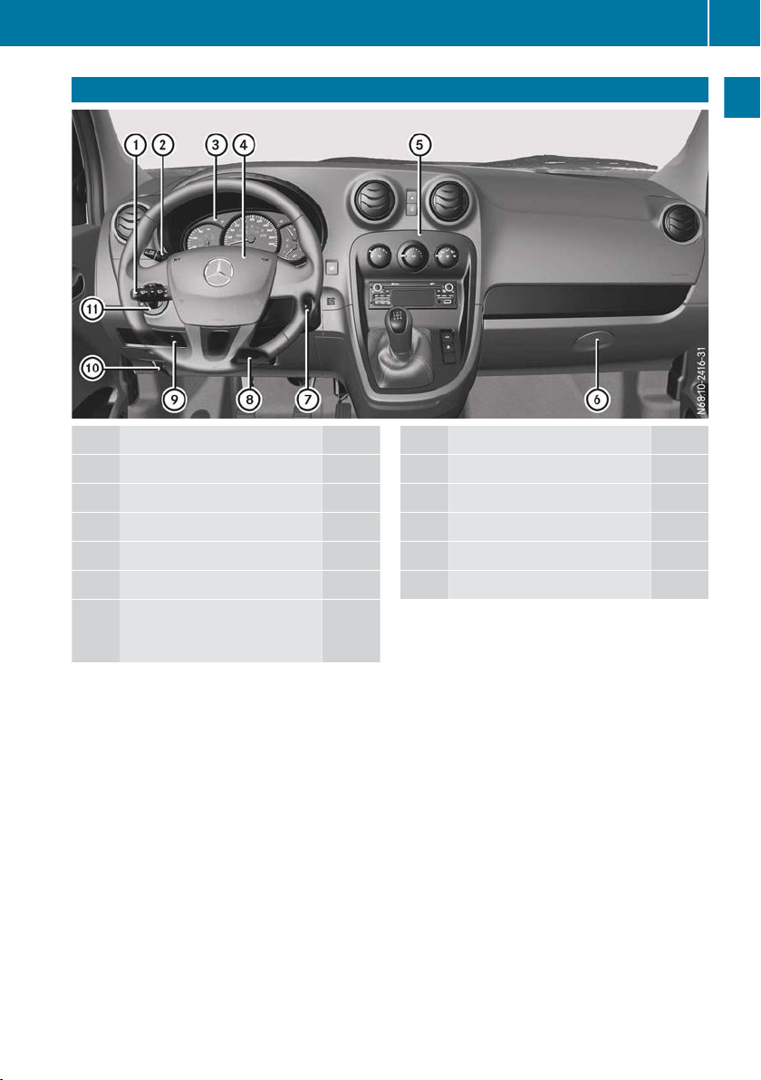
At a glance
Function Page
:
Combination switch 78
;
Cruise control lever 114
=
Instrument cluster 24
?
Horn
A
Centre console 27
B
Glove compartment or stowage compartment in the
instrument panel 142
Function Page
C
Ignition lock 103
D
Adjusting the steering wheel 72
E
Headlamp range control 77
F
Opens the bonnet 160
G
Light switch 76
Page 26
Instrument cluster and display
24
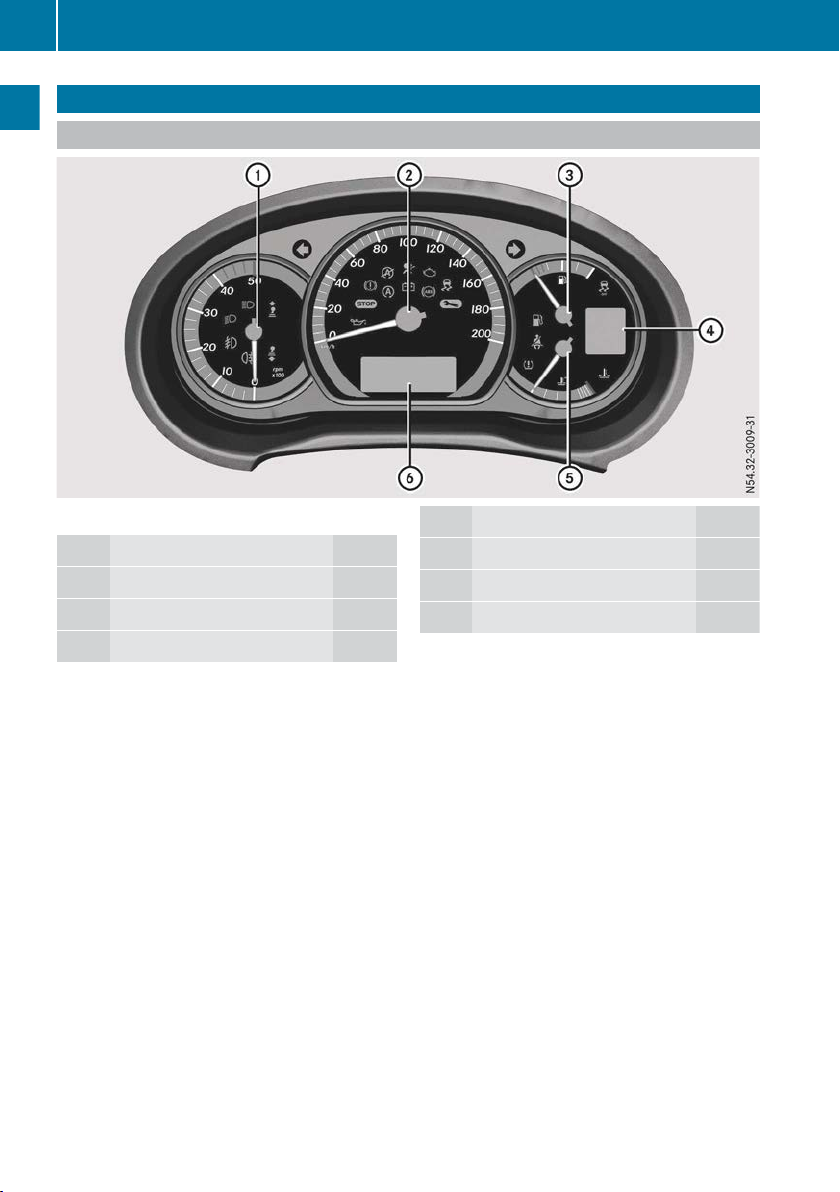
Instrument cluster and display
Displays and controls
At a glance
Instrument cluster: kilometres
i
Function Page
:
Rev counter 124
;
Speedometer 124
=
Fuel level 108
Function Page
?
Display screen 141
A
Coolant temperature 124
B
Multifunction display 125
Page 27
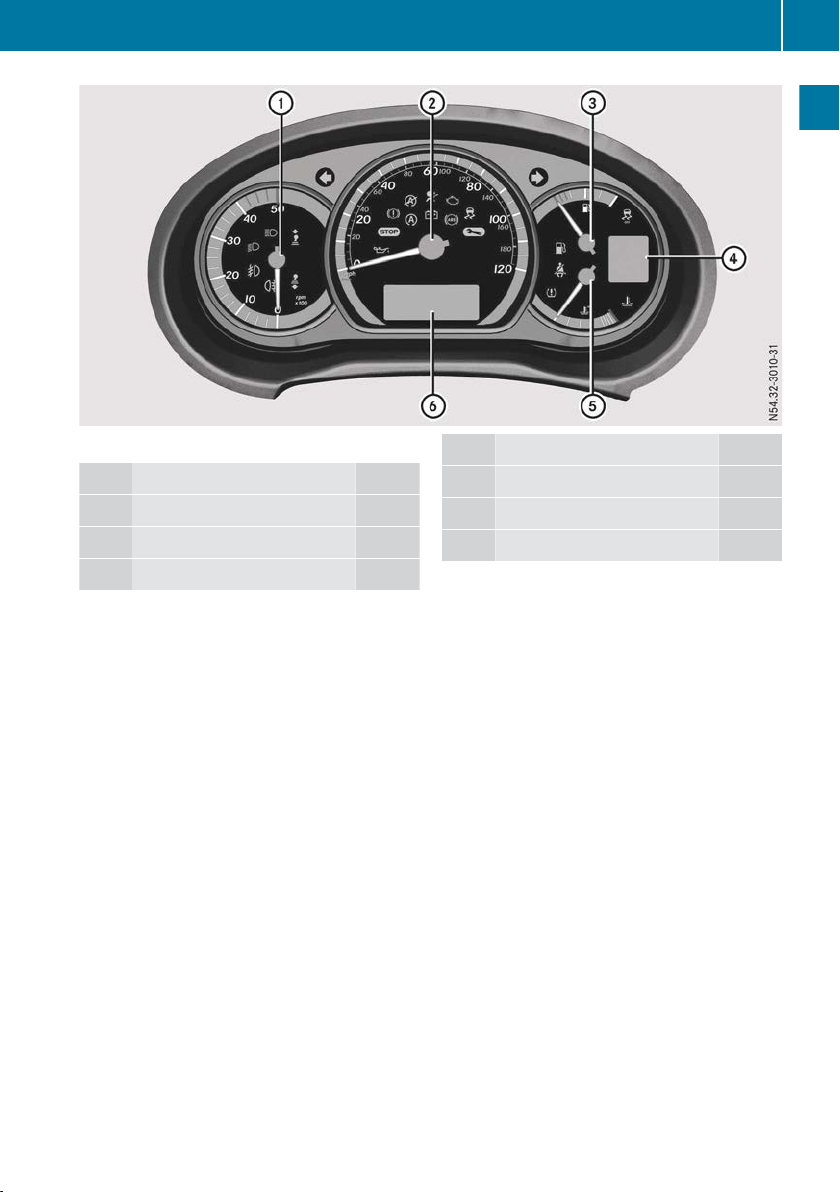
Instrument cluster: miles
i
Function Page
:
Rev counter 124
;
Speedometer 124
=
Fuel level 108
Instrument cluster and display
Function Page
?
Display screen 141
A
Coolant temperature 124
B
Multifunction display 125
25
At a glance
Page 28
Instrument cluster and display
26
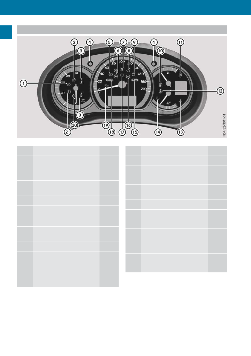
Indicator and warning lamps
At a glance
Example: indicator and warning lamps
Function Page
:
L Dipped-beam headlamps 77
;
K Main-beam headlamps
=
& * Gearshift indicator for reduced consumption 108
?
# ! Turn signal
A
J Parking brake/
malfunction in
tem
B
è ç Status indicator
for ECO start/stop function
C
6 Airbag
D
; Engine diagnostics
E
÷ ESP
÷ ASR
F
6 Reserve fuel
the brake sys-
®
78
78
136
104
137
139
49
48
141
Function Page
G
å ASR OFF
H
ü Seat belt
I
? Coolant
J
h Wireless tyre pressure
monitor 191
K
¯ Visit workshop
L
! ABS
M
# Battery
N
¤ Stop the vehicle and
switch off the engine 134
O
1 Engine oil level
P
R Rear foglamp
Q
N Front foglamps
48
32
139
134
136
140
140
77
77
Page 29
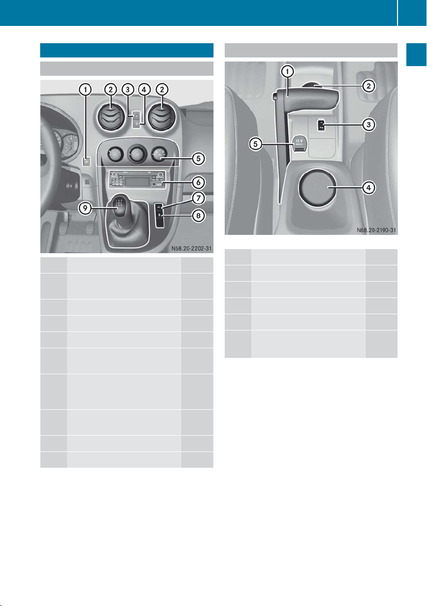
Centre console
27
Centre console
Upper section
Function Page
:
Operates the on-board computer 125
;
Air vents 101
=
Hazard warning lamps 79
?
Central locking 55
A
Control panel for climate
control systems 93
B
Radio or navigation system
including radio (see the separate operating instructions)
C
Activating/deactivating the
ECO start/stop function 104
D
Activates/deactivates ASR 48
E
Gear lever 107
Lower section
Centre console, lower section (example)
Function Page
:
Parking brake 111
;
Ashtray 157
=
Reversing aid 117
?
Cup holder 155
A
12 V socket 157
Cigarette lighter 157
At a glance
Page 30
Door control panel
28
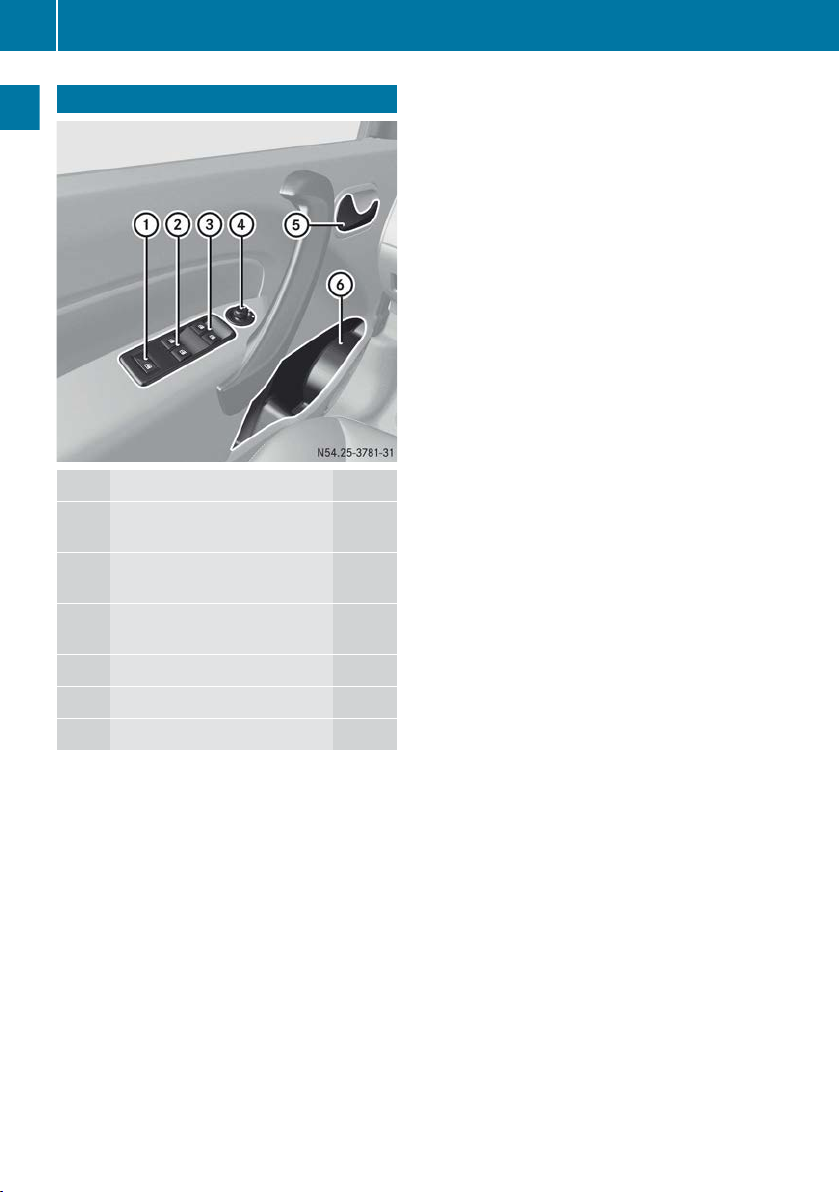
Door control panel
At a glance
Function Page
:
Override feature for side windows in the rear 62
;
Opens/closes rear side windows 62
=
Opens/closes front side windows 62
?
Adjusts the exterior mirrors 73
A
Opens the door 55
B
Stowage compartment 144
Page 31

Occupant safety
29
Useful information
These Operating Instructions describe all
i
models as well as standard and optional
equipment of your vehicle that was available
time of going to print. Country-specific
at the
variations are possible. Note that your vehicle
may not be fitted with all of the described
functions. This also applies to safety-relevant
systems and functions.
Read the information on qualified specialist
i
workshops (Y page 18).
Occupant safety
Restraint system introduction
The restraint
cle occupants coming into contact with parts of
the vehicle's interior in the event of an accident.
The restraint system can also reduce the forces
to which vehicle occupants are subjected during
an accident.
The restraint system comprises:
R
Seat belt system
R
Airbags
R
Child restraint system
R
Child seat securing systems
The components of the restraint system work in
conjunction with each other. They can only
deploy their protective function if all vehicle
occupants always:
R
fasten their seat belts correctly
(Y page 31)
R
adjust their seat and head restraint properly
(Y page 67).
As the driver, you also have to make sure that
the steering wheel is adjusted correctly.
Observe the information relating to the correct
driver's seat position (Y page 66).
You also have to make sure that an airbag can
inflate properly if deployed (Y page 33).
An airbag supplements a correctly fastened seat
belt. As an additional safety device, the airbag
increases the level of protection for vehicle
occupants in the event of an accident. For example, if the protection of the seat belt is sufficient
in an accident, the airbags are not deployed. In
the event of an accident, only the airbags that
increase protection in the relevant accident sit-
system can reduce the risk of vehi-
uation are deployed. However, seat belts and
airbags generally
do not protect against objects
penetrating the vehicle from the outside.
Information on the restraint system operation
can be found under "Triggering of belt tensioners and airbags" (Y page 35).
For more information about children travelling
with you in the vehicle, see "Children in the vehicle" (Y page 36).
Important safety notes
WARNING
G
If the restraint system is modified, it may no
longer work
as intended. The restraint system
may then not perform its intended protective
function by failing in an accident or triggering
unexpectedly, for example. There is an
increased risk of injury, possibly even fatal.
Never modify parts of the restraint system. Do
not attempt to modify the wiring as well as
electronic components or their software.
If it is necessary to modify an airbag system to
accommodate a person with disabilities, contact a Mercedes-Benz Service Centre.
Restraint system warning lamp
The functions of the restraint system are
checked after
regular intervals while the engine is running.
Therefore, malfunctions can be detected in
good time.
The 6 restraint system warning lamp in the
instrument cluster lights up when the ignition is
switched on. It goes out no later than a few seconds after the vehicle is started. The components of the restraint system are in operational
readiness.
A malfunction has occurred if the 6 restraint
system warning lamp:
R
does not light up after the ignition is switched
on
R
does not go out after a few seconds with the
engine running
R
lights up again while the engine is running
the ignition is switched on and at
Safety
Z
Page 32

Occupant safety
30
WARNING
G
If the restraint system is malfunctioning,
restraint system components may be triggered unintentionally or might not be triggered at
high rate of vehicle deceleration. This can
effect belt tensioners or airbags, for example.
There is an increased risk of serious or even
Safety
fatal injuries.
Have the restraint system checked and
repaired immediately at a qualified specialist
workshop.
all in the event of an accident with a
Seat belts
Introduction
A correctly fastened seat belt is the most effective means
cle occupants in the event of an accident or
overturn. This reduces the risk of vehicle occupants coming into contact with parts of the vehicle interior or being thrown from the vehicle. The
seat belt also helps to keep the vehicle occupants in the best position in relation to the airbag deployed.
The seat belt system consists of:
R
Seat belts
R
Belt tensioners and belt force limiters
If the seat belt is pulled quickly or suddenly from
the belt sash guide, the inertia reel locks. The
belt strap cannot be pulled out further.
The belt tensioner tightens the seat belt to lie
close against your body in the event of a collision. However, it does not pull the vehicle occupants back towards the seat backrest.
The belt tensioner also does not correct an
incorrect seat position or the strap layout of a
seat belt that is worn incorrectly.
When triggered, seat belt force limiters help to
reduce the peak force exerted by the seat belt
on the vehicle occupant.
The belt force limiters are synchronised with the
front airbags, which absorb part of the deceleration force, This makes it possible to reduce the
forces to which vehicle occupants are subjected
during an accident.
The belt tensioner is triggered regardless of the
lock status of the seat belt.
of restraining the movement of vehi-
Important safety notes
WARNING
G
The seat belt cannot perform its intended pro-
function
tective
Also, an improperly fastened seat belt can
cause additional injuries in the event of an
accident, sudden braking or abrupt changes
of direction. There is an increased risk of
injury, possibly even fatal.
Always make sure that all vehicle occupants
are wearing their seat belt properly and are
seated correctly.
WARNING
G
The seat belt does not offer the intended level
protection
of
rest to an almost vertical position. When braking or in the event of an accident, you could
slide underneath the seat belt and sustain
abdomen or neck injuries, for example. This
poses an increased risk of injury or even fatal
injury.
Adjust the seat properly before beginning
your journey. Always ensure that the backrest
is in an almost vertical position and that the
shoulder section of your seatbelt is routed
across the centre of your shoulder.
WARNING
G
Persons under 1.50 m tall cannot wear the
seat belts correctly without a suitable, additional restraint system. The seat belt cannot
perform
not fastened correctly. Also, an improperly
fastened seat belt can cause additional injuries in the event of an accident, sudden braking or abrupt changes of direction. There is an
increased risk of injury, possibly even fatal.
Secure persons less than 1.50 m tall in a suitable restraint system.
If a child younger than twelve years old and
under 1.50 m in height is travelling in the vehicle:
R
always secure the child in a child restraint
system suitable for this Mercedes-Benz vehi-
if it is not fastened correctly.
if you have not moved the back-
its
intended protective function if it is
Page 33

Occupant safety
31
cle. The child restraint system must be appropriate to
R
always observe the instructions and safety
the age, weight and size of the child.
notes on "Children in the vehicle" in this Owner's Manual (Y page 36) in addition to the
child restraint system manufacturer's installation instructions
WARNING
G
Seat belts cannot protect as intended, if:
R
they are
damaged, have been modified, are
extremely dirty, bleached or dyed
R
the seat belt buckle is damaged or
extremely dirty
R
modifications have been made to the belt
tensioners, belt anchorages or inertia reels
Seat belts may sustain non-visible damage in
an accident, e.g. due to glass splinters. Modified or damaged seat belts can tear or fail, for
example in the event of an accident. Modified
seat belt tensioners may be deployed unintentionally or fail to be deployed when
required. There is an increased risk of injury,
possibly even fatal.
Never modify safety belts, seat belt tensioners, seat belt anchorages and inertia reels.
Ensure that seat belts are not damaged or
worn and are clean. After an accident, have
the seat belts checked immediately at a qualified specialist workshop.
Mercedes-Benz recommends that you only use
seat belts which have been approved specifically for your vehicle by Mercedes-Benz. Otherwise, your vehicle's general operating permit
could be invalidated.
Correct use of the seat belts
Pay attention to the safety notes about the seat
belt (Y page 30
All vehicle occupants must fasten their seat
belts correctly before you start driving. You
must also make sure that all vehicle occupants
have fastened their seat belts correctly during
the journey.
).
When fastening your seat belt, always make
sure that:
R
the seat belt tongue is inserted into the belt
buckle that belongs to the seat.
R
the seat belt is tightened across your body.
Avoid wearing bulky clothing, e.g. a winter
coat.
R
the seat belt is not twisted.
Only then can the forces which occur be dis-
tributed over the area of the belt.
R
the shoulder section of the belt is routed
across the centre of your shoulder.
The shoulder section of the belt must not
come into
contact with your neck or be routed
under your arm. Where possible, adjust the
seat belt to the appropriate height.
R
The lap belt must be taut and as low as possible over your lap.
The lap belt must always be routed across
your hip joints and not across your abdomen.
Pregnant women must take particular care
with this. If necessary, push the lap belt down
to your hip joint and pull it tight using the
shoulder section of the belt.
R
The seat belt is not routed over sharp, pointed
or fragile objects.
If such objects are located on or in your clothing, e.g. pens, keys, spectacles, etc. stow
these in a suitable location.
R
Only one person should use each seat belt at
any one time.
Babies and children must never travel sitting
on the lap of another vehicle occupant. In the
event of an accident, they could be crushed
between the vehicle occupant and seat belt.
R
Do not secure any objects with a seat belt if
the seat belt is being used by one of the vehicle's occupants.
Also ensure that no objects are placed
between a person and the seat. e.g. a cushion.
Seat belts are solely intended to secure and
restrain persons. To secure objects, luggage or
loads, always observe the "Loading guidelines"
(Y page 142).
Vehicles with co-driver's bench seat: if the
i
inside co-driver's seat is not occupied, insert
the seat belt tongue into the belt buckle
belonging to that seat.
Safety
Z
Page 34
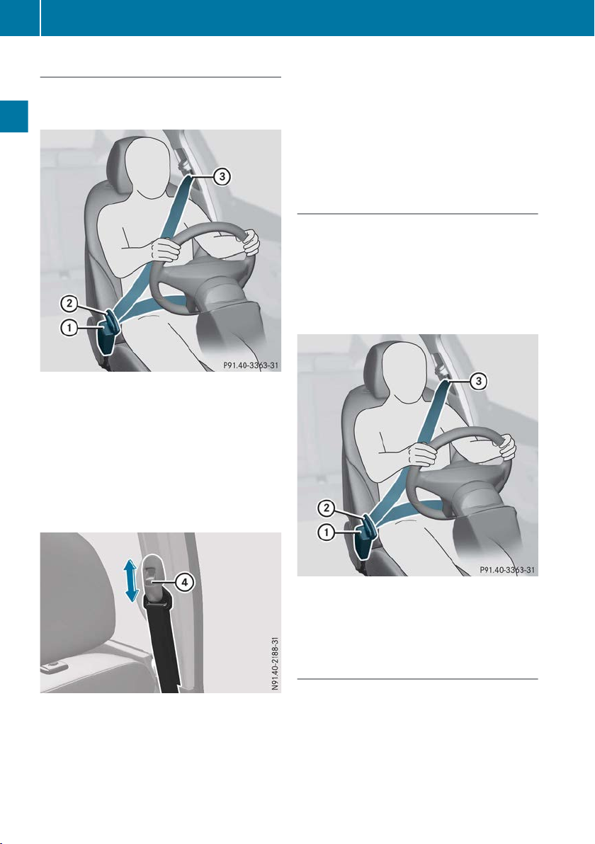
Occupant safety
32
Fastening and adjusting the seat belts
Observe the safety notes on the seat belt
(Y page 30
) and the information on the correct
use of the seat belt (Y page 31).
Safety
Basic illustration
X
Adjust the seat (Y page 66).
The seat backrest must be in an almost vertical position.
X
the seat belt smoothly from belt outlet =
Pull
and engage belt tongue ; into belt
buckle :.
X
If necessary, pull upwards on the shoulder
section of the seat belt to tighten the belt
across your body.
The shoulder section of the seat belt must
always be
routed across the centre of the shoul-
der. Adjust the belt outlet if necessary.
X
Press and hold belt outlet release ? and slide
it up or down.
X
Let go of belt outlet release ? in the
desired
position and make sure that the belt outlet
engages.
Releasing the seat belts
Make sure
!
Otherwise, the seat belt or belt tongue will be
trapped in the door or in the seat mechanism.
This could damage the door, the door trim
panel and the seat belt. Damaged seat belts
can no longer fulfil their protective function
and must be replaced. Visit a qualified specialist workshop.
that the seat belt is fully rolled up.
Basic illustration
X
Press release button :,
hold
belt tongue ;
firmly and guide it back towards belt outlet
=.
Belt warning for driver and co-driver
The 7 seat belt warning lamp in the instrument cluster
pants must wear their seat belts. It may light up
continuously or flash. In addition, a warning tone
may sound.
The 7 seat belt warning lamp goes out and
the warning tone ceases when the driver and the
front passenger have fastened their seat belt.
is a reminder that all vehicle occu-
Page 35

Occupant safety
33
Depending on the vehicle's equipment, the
7 seat belt warning lamp goes out and the
warning tone
ceases when the driver's seat belt
is fastened.
Airbags
Introduction
The installation location of an airbag is identified
by the AIRBAG symbol.
An airbag supplements a correctly worn seat
belt. It
is not a replacement for the seat belt. The
airbag offers additional protection in corresponding accident situations.
Not all airbags are deployed in an accident. The
different airbag systems work independently of
each other (Y page 35).
However, no system available today can completely eliminate injuries and fatalities.
It is also not possible to completely rule out a
risk of injury caused by an airbag due to the
speed at which the airbag must be deployed.
Important safety notes
WARNING
G
If you deviate from the correct seat position,
the airbag cannot perform its intended protective function and can even cause additional injuries when deployed. There is an
increased risk
In order to avoid such risks, always ensure
that all vehicle occupants:
R
fasten their seatbelts correctly, including
pregnant women
R
are seated correctly and maintain the furthest possible distance from the airbags
R
observe the following notes
Always ensure that there are no objects located between the airbag and the vehicle occupant.
R
Adjust the seats properly before beginning
your journey. Always make sure that the seat
is in an almost upright position. The centre of
of serious or even fatal injuries.
the head restraint must support the head at
about eye level.
R
Move the driver's and co-driver's seat as far
back as possible. The driver's seat position
must allow the vehicle to be driven safely.
R
Only hold the steering wheel by the rim; this
allows the airbag to deploy fully.
R
Always lean against the seat backrest when
the vehicle
is in motion. Do not lean forwards
or lean against the door or the side window.
Otherwise, you are in the airbags' deployment
area.
R
Always keep your feet in the footwell in front
of your seat. Do not place your feet on the
dashboard, for example. Otherwise, your feet
are in the airbag's deployment area.
R
For this reason, always secure persons less
than 1.50 m tall in suitable restraint systems.
The seat belt cannot be worn properly on people under this height.
If children are travelling in the vehicle, also
observe the following notes.
R
Always secure children younger than twelve
years of age and under 1.50 m tall in suitable
child restraint systems.
R
Child restraint systems should be fitted to the
rear seats.
R
Vehicles with co-driver's front airbag: if you
secure a child in a rearward-facing child
restraint system, always do so on a suitable
rear seat. The co-driver's front airbag cannot
be disabled.
R
Be sure to observe the instructions and safety
notes on "Children in the vehicle"
(Y page 36) and "Child restraint system on
the co-driver's seat" (Y page 39) in addition
to the child restraint system manufacturer's
installation instructions.
Objects in the vehicle interior could jeopardise the correct functioning of an airbag.
To prevent risks due to the required airbag
speed after deployment, ensure the following
before starting the journey:
R
there are no people, animals or objects
between the vehicle occupants and the airbag.
R
there are no objects between the seat, door
and B-pillar.
R
there are no hard objects, e.g. coat hangers,
hanging on the grab handles or coat hooks.
Safety
Z
Page 36

Occupant safety
34
R
no accessories, such as drinks can holders,
are attached
e.g. on doors or side windows.
R
there are no heavy, sharp or fragile objects in
the pockets of items of clothing. Stow such
objects in a suitable place.
WARNING
G
If you modify an airbag cover or affix objects
Safety
such as
function correctly. There is an increased risk
of injury.
Never modify an airbag cover or affix objects
to it.
in the airbag's deployment area,
stickers to it, the airbag can no longer
Front airbags
Driver's airbag : deploys in front of the steering wheel.
front of and above the glove compartment.
When deployed, the front airbags offer additional head and thorax protection on the driver's
and co-driver's seats.
Vehicles with a co-driver's bench seat: the
additional protection offered by the co-driver's
airbag is available to the person sitting in the
outer co-driver's seat in corresponding accident
situations. The person sitting on the inner codriver's seat is protected by a properly fastened
seat belt.
Co-driver's front airbag ; inflates in
into the seats. The airbags may then fail to
protect the vehicle occupants as intended.
There is an increased risk of injury, possibly
even fatal.
Use only
ically approved for the respective seat by
Mercedes-Benz.
Sidebags : deploy next to the outer cushions
of the seat backrest.
When deployed, the sidebag offers additional
thorax protection.
R
R
R
In the event of a side impact, the sidebag is
deployed on the side on which the impact
occurs.
seat covers which have been specif-
However, it does not protect:
the head
the neck
the arms
Windowbags
Sidebags
Sidebags are integrated on single front seats
depending on the vehicle equipment, see AIRBAG symbol on the outer side of the backrest.
WARNING
G
Unsuitable seat covers may obstruct or even
prevent deployment
of the airbags integrated
Windowbags : are integrated into the side of
the roof frame above the doors.
When deployed, the windowbag offers additional head protection. However, it does not
protect the thorax or arms.
Page 37

Occupant safety
35
In the event of a side impact, the windowbag is
deployed on the side on which the impact
occurs.
If the system determines that it can offer additional protection to that provided by the seat
belt, a windowbag may be deployed in other
accident situations (Y page 35
).
Deployment of belt tensioners and airbags
Important safety notes
WARNING
G
After the airbag deploys, the airbag parts are
hot. There is a risk of injury.
Do not touch the airbag parts. Have a
deployed airbag replaced at a qualified specialist workshop as soon as possible.
WARNING
G
Pyrotechnic seat belt tensioners that have
been deployed are no longer operational and
are unable to perform their intended protective function. This poses an increased risk of
injury or even fatal injury.
Therefore, have pyrotechnic belt tensioners
which have been triggered immediately
replaced at a qualified specialist workshop.
Mercedes-Benz recommends that you have the
towed
vehicle
after an accident. This is particularly important if
a belt tensioner or an airbag has been triggered.
If the belt tensioners or airbags are deployed,
you will hear a bang, and a small amount of
powder may also be released. The 6
restraint system warning lamp lights up.
Only in rare cases will the bang affect your hearing. The powder that is released generally does
not constitute a health hazard, however it may
cause short-term breathing difficulties to persons suffering from asthma or other pulmonary
conditions. If it is safe to do so, you should leave
the vehicle immediately or open a window in
order to prevent breathing difficulties.
to a qualified specialist workshop
Mode of operation
During the first stage of a collision, the restraint
system control unit evaluates important physical data
relating to vehicle deceleration or accel-
eration, such as:
R
duration
R
direction
R
intensity
Based on the evaluation of this data, the
restraint system control unit triggers the belt
tensioners in the event of a frontal or rear collision.
A belt tensioner can only be triggered if:
R
the ignition is switched on
R
the components of the restraint system are
operational. You can find further information
under "Restraint system warning lamp"
(Y page 29)
The belt tensioner can only be triggered if:
R
the ignition is switched on
R
the components of the restraint system are
operational. You can find further information
under "Restraint system warning lamp"
(Y page 29)
If the restraint system control unit detects a high
accident severity, additional components of the
restraint system are activated independently of
one another in certain frontal collision situations:
R
Driver's airbag
R
Co-driver's airbag
The activation thresholds for the belt tensioner
and airbag are determined by evaluating the
vehicle deceleration or vehicle acceleration that
occurs at different points in the vehicle. This
process is pre-emptive in nature. The triggering
process must take place in good time at the
start of the collision.
The vehicle's rate of deceleration or acceleration and the direction of the force are essentially
determined by:
R
the distribution of the force during the impact
R
the collision angle
R
the deformation characteristics of the vehicle
R
the characteristics of the object with which
the vehicle has collided
Factors which can only be seen and measured
after the collision has occurred do not play a
decisive role in the deployment of an airbag. Nor
Safety
Z
Page 38

Children in the vehicle
36
do they provide an indication of airbag deployment.
The vehicle
may be deformed significantly without an airbag being deployed. This is the case if
only parts which are relatively easily deformed
are affected and the rate of deceleration is not
high. Conversely, an airbag may be deployed
even though the vehicle suffers only minor
deformation. This is the case if, for example,
Safety
very rigid vehicle parts such as longitudinal body
members are hit, and sufficient deceleration
occurs as a result.
If the restraint system control unit detects a side
impact situation, the applicable components of
the restraint system are activated independently of each other.
R
Sidebag on the side on which the impact
occurs, independently of the belt tensioner
and of the use of the seat belt
R
Windowbag on the side on which the impact
occurs, independently of the use of the seat
belt and independently of whether the codriver's seat is occupied
R
Vehicles with a sidebag and/or windowbag:
seat belt tensioners, if the system determines
that they can offer additional protection for
the vehicle occupants in this situation
Not all airbags are deployed in an accident.
i
The various airbag systems work independently of one another.
How the airbag system works is determined
by the severity of the accident detected,
especially the vehicle deceleration or acceleration, and the apparent type of accident:
R
frontal collision
R
side impact
Children in the vehicle
Child restraint system
Important safety notes
Accident statistics show that children secured
in the
rear seats are safer than children secured
in the front seats. For this reason, MercedesBenz strongly advises that you fit a child
restraint system on a rear seat. Children are
generally better protected there.
If a child younger than twelve years old and
under 1.50 m
in height is travelling in the vehi-
cle:
R
always secure the child in a child restraint
system suitable for Mercedes-Benz vehicles.
The child restraint system must be appropriate to the age, weight and size of the child.
R
be sure to observe the instructions and safety
notes in this section in addition to the child
restraint system manufacturer's installation
instructions.
Vehicles with a twin co-driver's seat: the
middle seat is not suitable for installing a child
restraint system. Children under the age of
twelve and under 1.50 m in height are not permitted to travel on the middle seat.
WARNING
G
If you leave children unattended in the vehicle, they may be able to set the vehicle in
motion if, for example, they:
R
release the parking brake
R
shift the manual transmission into neutral
R
start the engine
In addition, they may operate vehicle equipment and become trapped. There is a risk of
an accident and injury.
When leaving
the vehicle, always take the key
with you and lock the vehicle. Never leave
children unattended in the vehicle.
WARNING
G
If persons (particularly children) are exposed
or cold for a prolonged period, there is
to heat
a risk of serious or even fatal injuries. Never
leave persons (particularly children) unattended in the vehicle.
WARNING
G
If the child restraint system is placed in direct
sunlight, the parts could become very hot.
Children could be suffer burns by touching
these parts,
in particular on the metallic parts
of the child restraint system. There is a risk of
injury.
If you and your child leave the vehicle, always
make sure that the child restraint system is
not in direct sunlight. Cover it with a blanket,
Page 39

Children in the vehicle
37
for example. If the child restraint system has
been exposed to direct sunlight, leave it to
cool down before securing the child in it.
Never leave children unattended in the vehicle.
Always ensure that all vehicle occupants have
their seat
properly. Particular attention must be paid to
children.
Observe the safety notes on the seat belt
(Y page 30) and the notes on how to use the seat
belt properly (Y page 31).
belts fastened correctly and are sitting
Child restraint system
Be sure to observe the correct use of the child
restraint system (
For safety reasons, Mercedes-Benz recommends that you only use a child restraint system
recommended by Mercedes-Benz
(Y page 45).
WARNING
G
If the child restraint system is incorrectly fitted on the seat position suitable for this purpose, it cannot perform its intended protective function. In the event of an accident,
braking
sharp
the child may not be held securely. There is an
increased risk of serious or even fatal injuries.
Observe the manufacturer's installation
instructions and the correct use for the child
restraint system. Make sure that the entire
surface of the child restraint system is resting
on the seat surface. Never place objects
under or behind the child restraint system,
e.g. cushions. Only use child restraint systems with the original cover designed for
them. Only replace damaged covers with genuine covers.
Y page 40).
or a sudden change in direction,
be restrained in the event of an accident, for
instance. There is an increased risk of injury,
possibly even fatal.
Always ensure
before fitting a rearward-facing child restraint
system on it.
WARNING
G
If the child restraint system is fitted incorrectly or is not secured, it can come loose in
the event of an accident, heavy braking or a
sudden change in direction. The child
restraint system
ing vehicle occupants. There is an increased
risk of injury, possibly even fatal.
Always fit child restraint systems properly,
even if they are not being used. Make sure
that you observe the child restraint system
manufacturer's installation instructions.
You will find further information on stowing
objects, luggage and loads securely under
"Loading guidelines" .
WARNING
G
Child restraint systems or their securing systems that
a load in an accident cannot perform their
intended protective function. In the event of
an accident, sharp braking or a sudden
change in direction, the child may not be held
securely. There is an increased risk of serious
or even fatal injuries.
Immediately replace child restraint systems
that have been damaged or subjected to a
load in an accident. Have the child restraint
securing systems checked in a qualified specialist workshop before fitting a child restraint
system again.
the rear seat is facing forwards
could be thrown about, strik-
have been damaged or subjected to
Safety
WARNING
G
If a rearward-facing child restraint system is
mounted facing forwards by mistake, it can-
provide
not
for example, be the case if a rearward-facing
child restraint system is fitted on a rear seat
which is facing backwards. The child cannot
the intended protection. This can,
Securing systems for child restraint systems
include:
R
the seat belt system
R
the ISOFIX securing rings
R
Top Tether anchorage points
If it is absolutely necessary to fit a child restraint
system on the co-driver's seat, be sure to
Z
Page 40

Children in the vehicle
38
observe the notes on "Child restraint systems
on the co-driver's seat" (Y page 39
Observe the warning labels in the vehicle interior and on the child restraint system.
It is advisable to use Mercedes-Benz care
i
products to clean child restraint systems recommended by Mercedes-Benz. You can
obtain information from any Mercedes-Benz
Service Centre.
Safety
).
ISOFIX child seat securing system
WARNING
G
ISOFIX child restraint systems do not offer
sufficient
weight is greater than 22 kg who are secured
using the safety belt integrated in the child
restraint system. The child could, for example,
not be restrained correctly in the event of an
accident. This poses an increased risk of
injury or even fatal injury.
If the child weighs more than 22 kg, only use
ISOFIX child restraint systems with which the
child is also secured with the vehicle seat belt.
Also secure the child restraint system with the
Top Tether belt, if available.
protective
effect for children whose
X
Install the ISOFIX child restraint system on
both ISOFIX securing rings :.
ISOFIX is a standardised securing system for
special child
seat2 and the rear bench seat. ISOFIX securing
rings : for ISOFIX child restraint systems are
located between the seat cushions and the seat
backrest and indicated by information tags on
the seat cushions.
Secure child restraint systems without an ISOFIX child seat securing system using the seat
belts in the vehicle. Always observe the notes on
using the child restraint system (Y page 40) as
well as the installation and operating instructions provided by the manufacturer for the child
restraint system being used.
restraint systems on the co-driver's
Always observe the notes on using the child
restraint system (Y page 40) as well as the
installation and operating instructions provided
by the manufacturer for the child restraint system being used.
Before each journey, make sure that the ISOFIX
child restraint system is properly engaged in
both ISOFIX securing rings.
When fitting the child restraint system,
!
make sure that the seat belt for the centre
seat does not get trapped. Otherwise, the
seat belt could be damaged.
2
Not every co-driver's seat is equipped with ISOFIX securing rings.
Top Tether
Introduction
Top Tether provides an additional connection
between
ISOFIX and the vehicle. It helps reduce the risk
of injury even further. If the child restraint system is fitted with a Top Tether belt, this should
always be used.
Important safety notes
G
If the rear seat backrests are not locked, they
could fold forwards in the event of an accident, heavy braking or sudden changes of
direction. As a result, child restraint systems
cannot perform their intended protective
function. Rear seat backrests that are not
locked can
child restraint system secured with
the
WARNING
also cause additional injuries, e.g.
Page 41

Children in the vehicle
39
in the event of an accident. This poses an
increased risk of injury or even fatal injury.
Always lock
rear seat backrests after fitting a
Top Tether belt. Adjust the rear seat backrests so that they are positioned upright.
Make sure that the backrest in the rear engages
fully. To do this, pull the backrest firmly.
Top Tether anchorage points
Example: rear bench seat
X
Co-driver's seat3:
attach
Top Tether hook =
to the lashing eyelet behind the guide rail of
the co-driver's seat. When doing so, make
sure Top Tether belt ? can move freely.
X
Fit the ISOFIX child restraint system with Top
Tether. Always
comply with the child restraint
system manufacturer's installation instructions when doing so.
Do not use the lashing eyelets in the load compartment if they are already being used to fasten
two of the following three components:
R
Safety net
R
Load in the load compartment
R
Child seat
Child restraint system on the co-driver's seat
General notes
Accident statistics show that children secured
in the
rear seats are safer than children secured
in the front-passenger seat. For this reason,
Mercedes-Benz strongly advises that you install
a child restraint system on a rear seat.
You can thus avoid the risks that could arise as
a result of an unsuitable positioning of the child
restraint system, e.g. too close to the dashboard.
Safety
Vehicles for Australia: for the middle seat,
i
there is a Top Tether anchorage located on
the rear side of the rear bench seat.
X
Rear seat bench: make sure that the rear
bench seat backrest is correctly engaged.
X
Slide head restraint : upwards.
X
Route the Top Tether belt ? under head
restraint : between the two head restraint
bars.
X
Rear bench seat:
Top Tether hook =
attach
to lashing eyelet ; in the load compartment.
When doing so, make sure Top Tether belt ?
can move freely.
3
Not every co-driver's seat is equipped with Top Tether anchorages.
Please observe the warning notice on the frontpassenger sun visor, see the illustration.
G
If you secure a child in a rearward-facing child
restraint system on the co-driver's seat, the
child can
if it is deployed in an accident.
WARNING
be hit by the co-driver's front airbag
Z
Page 42
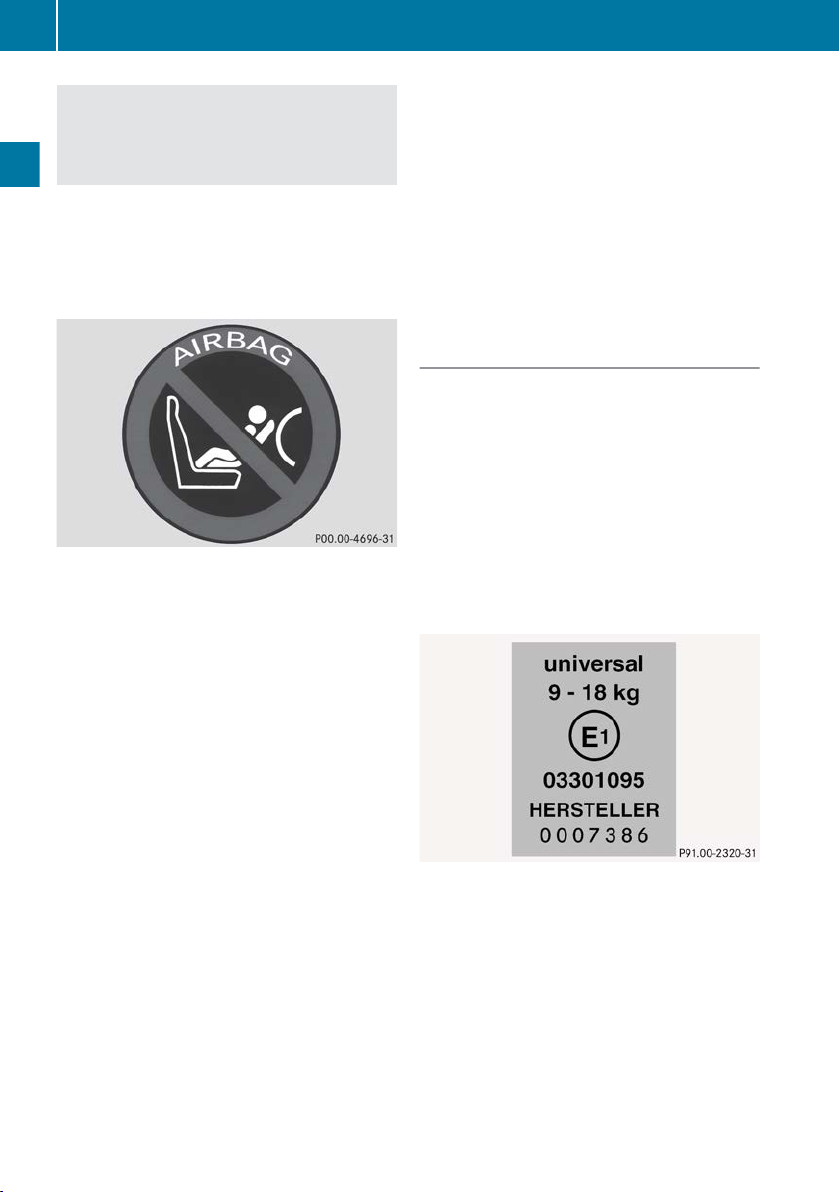
Children in the vehicle
40
There is an increased risk of injury, possibly
even fatal.
Therefore, always fit a rearward-facing child
restraint system on a suitable rear seat.
NEVER use
seat protected by an ACTIVE AIRBAG in front of
it; DEATH or SERIOUS INJURY to the CHILD can
occur.
Safety
a rearward facing child restraint on a
Rearward-facing child restraint system
Warning symbol for a rearward-facing child
restraint system.
The front-passenger front airbag cannot be disabled. This
sticker is affixed to the side of the dashboard on
the front-passenger side. The sticker is visible
when you open the front-passenger door.
Always fit the child restraint system to a suitable
rear seat (Y page 40).
Always observe the information on suitable
positioning of the child restraint system
(Y page 40) in addition to the child restraint
system manufacturer's installation and operating instructions.
is indicated by a special sticker. The
Forward-facing child restraint system
If it is absolutely necessary to fit a forwardfacing child restraint system to the frontpassenger seat, always move the frontpassenger seat as far back as possible. The
entire base of the child restraint system must
always rest on the seat cushion of the frontpassenger seat. The backrest of the child
restraint system must, as far as possible, lie flat
against the backrest of the front-passenger
seat. The child restraint system must not touch
the roof or be put under strain by the head
restraint. Adjust the angle of the seat backrest
and the head restraint position accordingly.
Always make sure that the shoulder belt strap is
correctly routed from the vehicle belt outlet to
the shoulder belt guide on the child restraint
system. The
forwards and downwards from the vehicle belt
outlet. If necessary, adjust the vehicle belt outlet and the front-passenger seat accordingly.
Always observe the information on suitable
positioning of the child restraint system
(Y page 40) in addition to the child restraint
system manufacturer's installation and operating instructions.
shoulder belt strap must be routed
Suitable positioning of the child
restraint system
Introduction
Only child
in accordance with the ECE standard ECE R44
are permitted for use in the vehicle.
For certain child restraint systems in weight category III, this can mean that the area of use is
restricted. The maximum size setting of the child
restraint system is not possible due to possible
contact with the roof.
Child restraint systems belonging to the "Universal" category can be recognised by their
orange approval label and the word "Universal".
Example: approval label on the child restraint system
“Universal” category
be used on the seats marked with U, UF or IUF
according to the tables “Suitability of the seats
for attaching a belt-secured child restraint system” or “Suitability of the seats for attaching an
ISOFIX child restraint system”.
Semi-universal child restraint systems are indicated by the text "Semi-universal" on the
approval label. These can be used if the vehicle
and the seat are listed in the child restraint system manufacturer's vehicle model list. For more
restraint systems which are approved
child restraint systems can
Page 43

information, contact the child restraint system
manufacturer or visit their website.
Child restraint system on the co-driver's
seat – if it is absolutely necessary to secure a
child in a child restraint system on the frontpassenger seat:
X
Always pay attention to the instructions under
"Child restraint system on the frontpassenger seat" (
Y page 39).
There you will find instructions on how to correctly route the shoulder belt strap from the
vehicle belt sash guide to the shoulder belt
guide on the child restraint system
(Y page 40).
X
Move the front-passenger seat as far back as
possible and into the highest position.
If you secure a child in a forward-facing child
restraint system on the front-passenger seat,
you must also move the front-passenger seat
to the highest position.
X
Move the backrest to an almost upright position.
The base of the child restraint system must lie
fully on the front-passenger seat cushion. The
backrest of a forwards-facing child restraint
system must, as far as possible, rest on the
backrest of the front-passenger seat. The
child restraint system may not touch the roof
or be put under strain by the head restraint.
Adjust the angle of the seat backrest and the
head restraint position accordingly. Also
observe the child restraint system manufacturer's installation instructions.
Children in the vehicle
41
Safety
Z
Page 44

Children in the vehicle
42
Suitability of the seats for attaching a belt-secured child restraint system
If you are using a baby car seat of weight category 0 or 0+, or a category I rearward-facing child
restraint system
that it does not come into contact with the child restraint system.
If you are using a category I, forward-facing child restraint system, you must remove the head
restraint of the respective seat (Y page 71), if possible. The backrest of the child restraint system
must, as far as possible, rest against the backrest of the seat.
In addition, always observe the notes found under “Child restraint system” (Y page 37), as well as
the child restraint system manufacturer's installation instructions.
Safety
When you remove the child restraint system, you must replace the head restraints again immediately (Y page 69). All vehicle occupants must adjust their head restraints correctly before beginning the journey.
Legend for the table:
X Seat that is not suitable for children of this weight category.
U Suitable for child restraint systems in the "Universal" category that are approved for use in this
weight category.
UF Suitable for forward-facing child restraint systems that belong to the "Universal" category and
are approved for use in this weight category.
L Suitable for child restraint systems as recommended; see the table “Recommended child
restraint systems” (Y
vehicle and the seat are listed in the child restraint system manufacturer's vehicle model list.
Front-passenger seat
on a rear seat, the driver's or front-passenger seat must be adjusted in such a way
page 45). Suitable for semi-universal child restraint systems if the
4
Weight category With front-
Carry cot/pushchair attachment at right angles to
the direction of travel
0
0+
I
II
III
4
Vehicles with
a twin front-passenger seat: the middle seat is not suitable for installing a child restraint system.
up to 10 kg X U, L
up to 13 kg X U, L
9 kg to 18 kg UF, L U, L
15 kg to 25 kg UF, L U, L
22 kg to 36 kg UF, L U, L
passenger
front airbag
X X
Without frontpassenger
front airbag
Page 45

Children in the vehicle
43
Rear seats
5, 6
Weight category Left, right Centre Rear seats in
the third row
Carry cot/pushchair attachment at right
7
U
X X
angles to the direction of travel
0
0+
I
up to 10 kg
up to 13 kg
9 kg to
U8, L
U8, L
8, 9
U
, L
8
8
8, 9
U8, L
U8, L
8, 9
U
, L
8
8
8, 9
X
X
UF
10, 11
, L
10, 11
18 kg
II
15 kg to
U9, L
9
U9, L
9
UF
10, 11
, L
10, 11
25 kg
III
22 kg to
U9, L
9
U9, L
9
UF
10, 11
, L
10, 11
36 kg
Suitability of the seats for attaching an ISOFIX child restraint system
If you are using a baby car seat of weight category 0 or 0+, or a category I rearward-facing child
restraint system
on a rear seat, the driver's or front-passenger seat must be adjusted in such a way
that it does not come into contact with the child restraint system.
If you are using a category I, forward-facing child restraint system, you must remove the head
restraint of the respective seat (Y page 71), if possible. The backrest of the child restraint system
must, as far as possible, rest against the backrest of the seat.
In addition, always observe the notes found under “Child restraint system” (Y page 37), as well as
the child restraint system manufacturer's installation instructions.
When you remove the child restraint system, you must replace the head restraints again immediately (Y page 69). All vehicle occupants must adjust their head restraints correctly before beginning the journey.
Legend for the table:
X ISOFIX position that is not suitable for ISOFIX child restraint systems in this weight category
and/or size category.
IUF Suitable for forward-facing ISOFIX child seat securing systems that belong to the "Universal"
category which are approved for use in this weight category.
IL Suitable for ISOFIX child restraint systems as recommended; see the following table of "Rec-
ommended child restraint systems" (Y page 45).
Safety
5
If you are using a baby car seat in the 0 or 0+ category on a rear seat, you must adjust the driver or frontpassenger seat so that the seat does not touch the baby car seat.
6
Child restraint systems are not permitted on a rear bench seat with a partition grille.
7
Fit the
pushchair attachment across at least two seats. The child's head must be facing towards the centre
of the vehicle.
8
Move the front seat as far forward as possible when fitting the child seat. Then slide the front seat backwards
as specified in the child seat operating instructions. The front seat must not touch the child seat.
9
The child seat backrest must lie flush against the vehicle seat backrest. Adjust the head restraint height or
remove the head restraint completely. Move the seat in front of the child seat in the fore-and-aft direction to
the centre position. Do not tilt the seat backrest in front of the child seat more than 25°.
10
Move the rear seats in the third row to the rearmost position of the fore-and-aft adjustment.
11
The child seat backrest must lie flush against the vehicle seat backrest. Adjust the head restraint height or
remove the head restraint completely.
Z
Page 46

Children in the vehicle
44
The manufacturer will also recommend a suitable ISOFIX child restraint system. For this, your
vehicle and
the seat must be listed in the child restraint system manufacturer's model list. For
more information, contact the child restraint system manufacturer or visit their website.
Front-passenger seat
Weight category Size catego-
12, 13
ries
With frontpassenger
front airbag
Safety
Carry cot/pushchair attachment at
right angles to the direction of travel
0
up to 10 kg
F X X
G X X
E X IL
up to approximately 6 months
0+
up to 13 kg
up to approximately 15 months
E X IL
D X IL
C X IL
I
9 kg to 18 kg
between approximately 9 months
and 4 years
D IUF, IL IUF, IL
C IUF, IL IUF, IL
B IUF, IL IUF, IL
B1 IUF, IL IUF, IL
A IUF, IL IUF, IL
Rear seats
14
Without front-
passenger
front airbag
Weight category Size cate-
gories
Left, right Centre Rear seats,
third row of
seats
Carry cot/pushchair attachment at right angles to the
direction of travel
0
up to 10 kg
F
G
E
15
IL
15
IL
16
IL
X X
X X
X X
up to approximately
6 months
0+
up to 13 kg
up to approximately
15 months
12
Vehicles with
13
Not all front-passenger seats are fitted with ISOFIX child seat securing systems.
14
Child restraint systems are not permitted on a rear bench seat with a partition grille.
15
Fit the pushchair attachment across at least two seats. The child's head must be facing towards the centre
of the vehicle.
16
Move the front seat as far forward as possible when fitting the child seat. Then slide the front seat backwards
as specified in the child seat operating instructions. The front seat must not touch the child seat in the
process.
a twin front-passenger seat: the middle seat is not suitable for installing a child restraint system.
E
D
16
IL
16
IL
X X
X X
Page 47

Children in the vehicle
45
Weight category Size cate-
gories
Left, right Centre Rear seats,
third row of
seats
I
9 kg to 18 kg
between approximately
9 months and 4 years
C
D
C
B
B1
A
IL
IL
IL
IL
IL
16
IL
16, 17
16, 17
16, 17
16, 17
16, 17
X X
X X
X X
X X
X X
X X
The child restraint system must not touch the roof or be subjected to a load by the head restraint.
Adjust the head restraint position accordingly. Also observe the child restraint system manufacturer's installation instructions.
Move the front seat to the highest position.
Recommended child restraint systems
Always observe the information on "Child restraint systems on the front-passenger seat"
(Y page 39
You can obtain further information about the correct child restraint system from any Mercedes-Benz
Service Centre.
Weight and age categories
Category 0+: up to
13 kg
up to approximately
18 months
) and on "Suitable positioning of the child restraint system" (Y page 40).
Manufacturer Type Order number
Britax Römer
BABY SAFE PLUS
BABY SAFE ISOFIX
18, 19
plus
18
A 000 970 10 00
B6 6 86 8224
Safety
16
Move the
as specified in the child seat operating instructions. The front seat must not touch the child seat in the
process.
17
The child seat backrest must lie flush against the vehicle seat backrest. Adjust the head restraint height or
remove the head restraint completely. Move the seat in front of the child seat to the centre position in the foreand-aft direction. Do not tilt the seat backrest in front of the child seat more than 25°.
18
Secured with a three-point seat belt
19
Secured with an ISOFIX child seat securing system
front seat as far forward as possible when fitting the child seat. Then slide the front seat backwards
Z
Page 48

Children in the vehicle
46
Weight and age cat-
Manufacturer Type Order number
egories
Category I: 9 to
Britax Römer
18 kg
between approx-
imately 8 months
and 4 years
Safety
Group II/III: 15 to
Britax Römer
36 kg
between approx-
imately 3.5
and
12 years
Child-proof locks
Important safety notes
WARNING
G
If children are travelling in the vehicle, they
could:
R
open doors,
or road users
R
exit the vehicle and be caught by oncoming
traffic
R
operate vehicle equipment and become
trapped, for example
There is a risk of an accident and injury.
Always activate the child-proof locks and
override feature if children are travelling in the
vehicle. When leaving the vehicle, always take
the key with you and lock the vehicle. Never
leave children unattended in the vehicle.
thus endangering other people
DUO plus
18, 21
KIDFIX
20
A 000 970 16 00
A 000 970 19 00
18,
In addition, they may operate vehicle equipment and become trapped. There is a risk of
an accident and injury.
When leaving
the vehicle, always take the key
with you and lock the vehicle. Never leave
children unattended in the vehicle.
Child-proof locks for rear doors
If children are travelling in the vehicle, you can
activate the child-proof locks for the rear.
You can use the child-proof lock to secure the
rear doors individually.
WARNING
G
If you leave children unattended in the vehicle, they may be able to set the vehicle in
motion if, for example, they:
R
release the parking brake
R
shift the manual transmission into neutral
R
start the engine
18
Secured with a three-point seat belt
20
Secured with an ISOFIX child seat securing system and Top Tether
21
Secured with a three-point seat belt and an ISOFIX child seat securing system
Left-hand side of vehicle (example)
X
To activate: push the latch upwards :.
X
To deactivate:
X
Then, make sure that the child-proof locks are
working properly.
push
the latch downwards ;.
Page 49

Driving safety systems
47
A door with an activated child-proof lock cannot
be opened
from the outside if the vehicle is unlocked.
from the inside. It can only be opened
Pets in the vehicle
WARNING
G
If you leave animals unsupervised or unsecured in the vehicle, they may push a button
or a switch, for example.
They could:
R
activate vehicle equipment and become
trapped, for example
R
switch vehicle systems on or off, thus
endangering other road users
event of an accident, sudden braking or
In the
abrupt changes of direction, unsecured animals could be flung around the vehicle, injuring the vehicle occupants. There is a risk of an
accident and injury.
Never leave animals unattended in the vehicle. Always secure animals correctly during a
journey, e.g. in an animal transport box.
Driving safety systems
Driving safety systems overview
This section
ing driving safety systems:
R
ABS (Anti-lock Braking System)
R
ESP® (Electronic Stability Program) with
understeering control
R
ASR (acceleration skid control or Acceleration Slip Regulation)
R
BAS (Brake Assist System)
contains information on the follow-
Important safety notes
If you
fail to adapt your driving style, the driving
safety systems can neither reduce the risk of
accident nor override the laws of physics. Driving safety systems are merely aids designed to
assist driving. You are responsible for the distance to the vehicle in front, for vehicle speed
and for braking in good time. Always adapt your
driving style to the prevailing road and weather
conditions as well as the traffic conditions and
maintain a sufficient, safe distance from other
road users. Drive carefully.
Only with
i
tyres and the road can the described driving
safety systems attain their maximum effectiveness. Pay special attention to the notes on
tyres, the recommended minimum tyre tread
depths, etc., in the "Wheels and tyres" section
(Y page 187).
Use winter tyres (M+S tyres), with snow
chains if necessary, when the conditions are
wintry. Only then will the driving safety systems described in this section achieve their
maximum effect.
the best possible contact between
ABS (Anti-lock Braking System)
Important safety notes
Note the
i
(Y page 47).
G
If ABS is faulty, the wheels could lock when
braking. The steerability and braking characteristics may be severely impaired. Additionally, further driving safety systems are deactivated.
ding and accidents.
Drive on carefully. Have ABS checked immediately at a qualified specialist workshop.
If ABS is malfunctioning, other systems will also
fail, including driving safety systems. Observe
the information relating to the ABS warning
lamp (Y page 136) and to the messages which
may be displayed in the instrument cluster
(Y page 129).
ABS controls the braking pressure so that the
wheels do not lock when braking. This maintains
the steerability of your vehicle while braking.
ABS acts from a speed of about 8 km/h
upwards, regardless of road surface conditions.
On a slippery road surface, ABS intervenes even
if you only brake gently.
The yellow ! ABS warning lamp in the instru-
ment cluster lights up when the ignition is
switched on. The lamp goes out when the engine
starts running.
section on 'Important safety notes'
WARNING
There
is an increased danger of skid-
Safety
Z
Page 50

Driving safety systems
48
Braking
X
If ABS intervenes: keep the brake pedal
firmly depressed until the braking situation
has passed.
X
To make a full brake application: depress
the brake pedal with full force.
If ABS intervenes when braking, you will feel a
pulsating in the brake pedal.
Safety
The pulsating brake pedal can be an indication
of hazardous
road conditions and functions as a
reminder to take extra care while driving.
ASR (acceleration skid control)
Important safety notes
Note the
i
(Y page 47).
ASR improves traction, i.e. the transfer of power
from the tyres to the road surface, for a sustained period and, thereby, also improves the
driving stability of the vehicle. ASR assists you
when pulling away and accelerating, especially
on smooth and slippery surfaces.
ASR brakes the individual drive wheels and limits the engine torque. This prevents the drive
wheels from spinning.
If traction on the road surface is not sufficient,
even ASR will not allow you to pull away without
difficulty. This also applies when tyres, load and
gradient are taken into account.
If ASR malfunctions, engine power output may
be reduced.
ASR can neither reduce the risk of an accident
nor suspend the laws of physics if the driver
does not pay attention when pulling away or
accelerating. ASR is only an aid. Always adapt
your driving style to suit the prevailing road and
weather conditions.
section on 'Important safety notes'
Activating/deactivating ASR
WARNING
G
If deactivated, ASR will not attempt to stabilise the
vehicle during pulling away and acceleration. There is an increased risk of skidding
and of an accident.
Only deactivate ASR in the situations described in the following.
It may be best to deactivate ASR briefly in the
following situations:
R
if snow chains are being used
R
in deep snow
R
on sand or gravel
If the brake system is used for prolonged
!
periods because
ESP intervenes frequently, it
can overheat or even be damaged. Therefore,
only deactivate ASR briefly.
If you deactivate ASR:
R
engine torque is not limited and the drive
wheels are able to spin. The spinning wheels
produce a cutting effect which improves traction.
R
traction control still intervenes by braking if
one drive wheel reaches its grip limit, e.g. if
the surface under one side of the vehicle is
slippery. In this situation, the wheel is then
braked to increase traction.
If you deactivate ASR, ESP® will
still intervene to
stabilise the vehicle. When ESP® is intervening
and the ÷ warning lamp in the instrument
cluster is flashing, leave ASR on. In this case,
only depress the accelerator pedal as far as
required when pulling away.
X
To deactivate: press button :.
The å warning lamp in the instrument
cluster lights up. In addition, the Slippery
surface
message
is shown in the instrument
cluster.
If
is not switched off, the Normal sur‐
ASR
i
face message is shown in the instrument
cluster.
ASR will switch on again automatically:
R
if you are driving faster than 50 km/h or
R
the vehicle handling becomes unstable.
ASR is automatically activated when the engine
is started.
Page 51

Driving safety systems
49
The ECO start/stop function automatically
switches the
ped. When pulling away again, the engine starts
automatically. ASR then remains in the previously selected status. For example: if ASR was
deactivated before the engine was automatically switched off, ASR will also remain off after
the engine is automatically started.
engine off when the vehicle is stop-
ESP® (Electronic Stability Program)
Note the
i
(Y page 47).
G
If ESP® is malfunctioning it will not provide
any vehicle stabilisation. There is an
increased risk of skidding or of an accident.
Exercise caution when continuing to drive.
Have ESP® checked at a qualified specialist
workshop.
If ESP® is malfunctioning, the ÷ indicator
lamp lights up while the engine is running and
the engine power may be reduced
(Y page
ESP® monitors driving stability and detects
understeering or oversteering (skidding) in good
time. If ESP® detects that the vehicle is deviating from the direction desired by the driver, one
or more wheels are braked to stabilise the vehicle. The engine output is also modified to keep
the vehicle on the desired course within physical
limits. ESP® greatly assists you when driving on
wet or slippery road surfaces. ESP® also stabilises the vehicle when braking.
The ÷ warning lamp in the instrument cluster
flashes when ESP® is intervening.
If ESP® intervenes:
X
ASR must not be switched off under any circumstances.
X
When pulling away, only depress the accelerator pedal as far as required.
X
Adapt your driving style to suit the prevailing
road and weather conditions.
section on 'Important safety notes'
WARNING
137
).
BAS (Brake Assist)
Note the
i
(Y page 47).
G
If BAS is malfunctioning, the braking distance
in an emergency braking situation is
increased. There is a risk of accident.
In an emergency braking situation, depress
the brake pedal with full force. ABS prevents
the wheels from locking.
Brake Assist
uations. If you depress the brake quickly, BAS
automatically increases the brake pressure,
thereby reducing the stopping distance.
When you release the brake pedal, the brakes
function as usual again. BAS is deactivated.
section on 'Important safety notes'
WARNING
operates in emergency braking sit-
Protection against theft
Immobiliser
The immobiliser prevents your vehicle from
being started without the correct key.
X
To activate: remove
lock.
X
To deactivate: turn the key to position 2 in
the ignition lock.
Always take the key with you and lock the vehicle when
in the vehicle, anyone can start the engine.
i
leaving the vehicle. If you leave the key
Starting the engine always deactivates the
immobiliser.
the key from the ignition
ATA (Anti-Theft Alarm system)
When ATA is primed, a visual and audible alarm
is
triggered
is detected in the vehicle interior. This can occur
if someone reaches into the vehicle interior, for
example.
if the bonnet is opened or movement
Safety
wheels with the recommended tyre
only
Use
i
sizes. Only then will ESP® function properly.
Z
Page 52

Driving safety systems
50
Sensors in the vehicle interior
Safety
:
Sensors in the A-pillar
Switching on
X
Make sure that:
R
the side windows are closed
R
the front tilting skylights are closed
R
no objects, such as mascots, are dangling
in front of sensors :
This will prevent false alarms.
X
Make sure that:
R
the doors are closed
R
the tailgate is closed or the rear doors are
closed
R
the bonnet is closed
Only then can ATA be activated.
X
Lock the vehicle with the key.
ATA is primed after approximately ten seconds.
Switching off
X
Unlock the vehicle with the key.
or
X
Insert the key into the ignition lock.
ATA switches off automatically.
Page 53

Key
51
Useful information
These Operating Instructions describe all
i
models as well as standard and optional
equipment of your vehicle that was available
time of going to print. Country-specific
at the
variations are possible. Note that your vehicle
may not be fitted with all of the described
functions. This also applies to safety-relevant
systems and functions.
Read the information on qualified specialist
i
workshops (Y page 18).
Key
Key functions
Important safety notes
WARNING
G
If children are left unattended in the vehicle,
they could:
R
doors,
open
or road users
R
exit the vehicle and be caught by oncoming
traffic
R
operate vehicle equipment and become
trapped
Children could also set the vehicle in motion
by, for example:
R
releasing the parking brake
R
shifting the manual transmission into neutral
R
starting the engine
There is a risk of an accident and injury.
When leaving the vehicle, always take the key
with you and lock the vehicle. Never leave
children and animals unattended in the vehicle. Keep the key out of the reach of children.
thus endangering other people
Do not attach any heavy or large objects to the
key. Remove
any bulky keyrings before insert-
ing the key into the ignition lock.
Keep the key away from strong magnetic
!
fields. Otherwise, the remote control function
could be affected.
Strong magnetic fields can occur in the vicinity of powerful electrical installations.
Do not keep the key:
R
with electronic devices, e.g. a mobile phone
or another key
R
with metallic objects, e.g. coins or metal foil
R
in metallic objects, e.g. metal cases
Key overview
Folding key
:
& To lock the vehicle
;
% To unlock the vehicle
=
Key for ignition lock, fuel filler cap and righthand front door
?
To fold the key in and out
Opening and closing
WARNING
G
If you attach heavy or large objects to the key,
key
could be unintentionally turned in the
the
ignition lock. This could cause the engine to
be switched off. There is a risk of an accident.
Z
Page 54

Key
52
Fixed key
:
& To lock the vehicle
;
% To unlock the vehicle
=
Key for ignition lock, fuel filler cap and righthand front door
Folding the key in and out
X
To fold out: press button ?.
Opening and closing
X
To fold in:
press button ?
and fold in key =
until it engages.
X
Release button ?.
Locking and unlocking centrally
The key centrally locks/unlocks:
R
the doors
R
the sliding doors
R
the tailgate/rear doors
X
To unlock centrally: press the % but-
ton ;.
The turn signals flash once.
If you do not open the vehicle within approximately 120 seconds of unlocking, the vehicle
will lock again.
X
To lock centrally: press
The turn signals flash twice.
the & button :.
Selective locking of the doors, only
right-hand drive vehicles
X
To lock: press the & button :.
All doors are locked. The turn signals flash
twice.
X
To unlock: press the % button ;.
The driver's door unlocks. The turn signals
flash once.
X
Press the % button ;
twice in quick succession.
All doors are unlocked. The turn signals flash
once.
Double lock function, only right-hand
drive vehicles
On vehicles with the double lock function, all
doors can be locked and may no longer be
opened from
the inside. If the side windows are
open or have been smashed in, for example, the
doors may no longer be opened from the inside.
X
To activate the double lock function: press
the & button : twice in quick succession.
The double lock function is activated. The
indicator lamps flash twice and then a further
five times at a quicker rate.
The double
i
lock function is not permanently
activated and must be reactivated every time
it is required.
Battery of the key
Important safety notes
WARNING
G
Batteries contain toxic and corrosive substan-
batteries are swallowed, it can result in
ces. If
severe health problems. There is a risk of fatal
injury.
Keep batteries out of the reach of children. If
a battery is swallowed, seek medical attention
immediately.
Environmental note
H
Batteries contain pollutants.
It is
with the household rubbish.
They must be collected sep-
illegal to dispose of them
Page 55

arately and disposed of in an
environmentally responsible
recycling system.
Dispose of batteries in an
environmentally responsible
manner. Take discharged
batteries to a qualified specialist workshop or to a collection point
for used batter-
ies.
Mercedes-Benz recommends that you have batteries changed at a qualified specialist workshop.
Changing the battery
You can obtain suitable batteries from a qualified specialist
battery is approximately two years.
workshop. The operating life of a
X
Lift off cover : (arrow) using a screwdriver,
for example.
X
Both keys: remove cover :.
Folding key
Key
53
Opening and closing
Folding key
Fixed key
X
Folding key: lift off cover : using a coin.
X
Fixed key: remove screw ;.
Fixed key
X
Remove battery =.
X
Clean new battery = with a lint-free cloth.
X
Insert the new battery with the positive terminal
downwards. Use a lint-free cloth
facing
to do so.
X
Insert cover : and press it closed until it
engages.
X
Check the function of the % and &
buttons on the vehicle.
Z
Page 56

Key
54
Problems with the key
Problem
You cannot lock or
unlock the vehicle using
the key.
Opening and closing
You have lost a key.
Possible causes/consequences and M Solutions
The key battery is weak or discharged.
X
Try again to lock/unlock the vehicle using the remote control function of the key. Point the tip of the key at the driver's door handle
from close range and press the % or & button.
If this does not work:
X
Replace the key battery, if required (Y page 53
).
If this does not work:
X
Lock the vehicle with the emergency key element (Y page 56).
The key is faulty.
X
Lock the vehicle with the emergency key element (Y page 56
X
Have the key checked at a qualified specialist workshop.
The starter battery is discharged.
X
Charge the starter battery (Y page 175
).
The starter battery is discharged and cannot be charged.
X
Lock or unlock the left-hand front door manually (Y page 56
X
Lock the right-hand front door manually (Y page 57).
X
Lock the sliding door manually (Y page 58).
X
Lock the left-hand rear door manually (Y page 60)
X
Unlock the tailgate manually from the inside (Y page 61)
X
Have the key deactivated at a qualified specialist workshop.
X
Report the loss immediately to the vehicle insurers.
X
If necessary, have the mechanical locks replaced.
).
).
The engine cannot be
started using the key.
The on-board voltage is too low.
X
Switch off non-essential consumers, e.g. seat heating or interior
lighting, and try to start the engine again.
If this does not work:
X
Check the starter battery and charge it if necessary (Y page 175).
or
X
Jump-start the vehicle (
Y page 179).
or
X
Consult a qualified specialist workshop.
An attempt was made to start the vehicle with the wrong key.
X
Turn the correct key for the vehicle to position 2 in
X
Wait for approximately 20 seconds.
the ignition lock.
The immobiliser is deactivated.
X
Start the engine.
Page 57
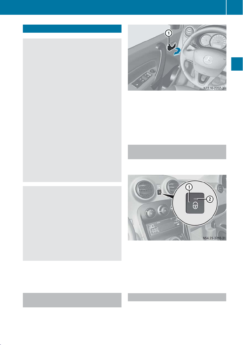
Doors
WARNING
G
If children are left unattended in the vehicle,
they could:
R
open doors,
or road users
R
exit the vehicle and be caught by oncoming
traffic
R
operate vehicle equipment and become
trapped
Children could also set the vehicle in motion
by, for example:
R
releasing the parking brake
R
shifting the manual transmission into neutral
R
starting the engine
There is a risk of an accident and injury.
When leaving the vehicle, always take the key
with you and lock the vehicle. Never leave
children and animals unattended in the vehicle. Keep the key out of the reach of children.
thus endangering other people
Doors
Example: driver's door
X
Pull door handle :.
The door unlocks and opens.
In the right-hand section of the instrument
i
cluster there is a display that indicates if a
door is open or not closed properly.
Centrally locking and unlocking the vehicle from the inside
You can centrally lock and unlock the vehicle
from the inside.
55
Opening and closing
WARNING
G
When the double locks are activated, the
doors can no longer be opened from the
inside. People
in the vehicle can no longer get
out, e.g. in hazardous situations. There is a
risk of injury.
Therefore, do not leave any people unsupervised in the vehicle, particularly children, elderly people or people in need of special assistance. Do not activate the double lock when
people are in the vehicle.
Stow luggage or cargo preferably in the load
compartment. Observe the loading guidelines
(Y page 142).
Unlocking and opening the doors from the inside
You can also open the driver's or co-driver's
door from the inside at any time, even if it is
locked.
X
To lock: with the doors closed, press button :.
Indicator lamp ; in the button lights up.
X
To unlock: with the doors closed, press button :.
Indicator lamp ; in the button goes out.
Automatic locking feature
If you
activate the "Automatic locking" function,
the vehicle doors lock automatically from a
speed of 7 km/h.
Z
Page 58
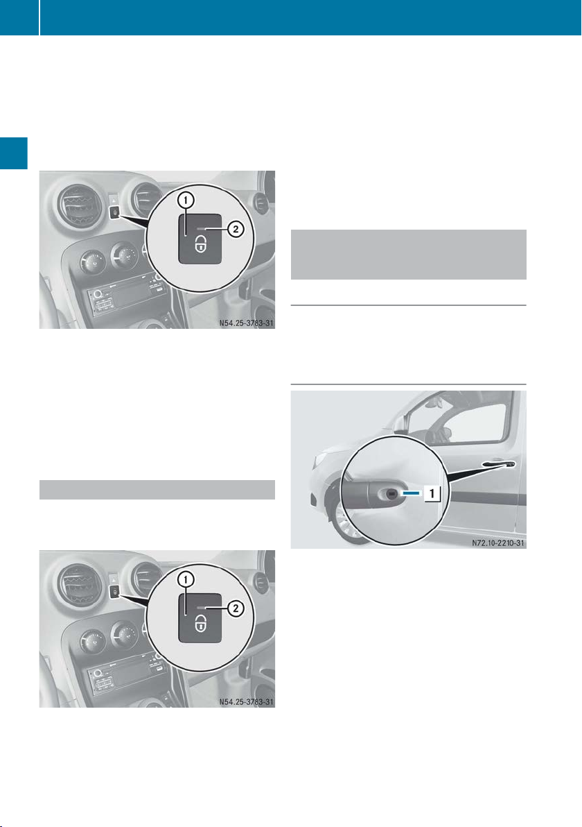
56
Doors
The vehicle is locked automatically when the
ignition is
switched on and the wheels are turn-
ing.
You could therefore be locked out if:
R
the vehicle is being pushed.
R
the vehicle is being towed.
R
the vehicle is being tested on a dynamometer.
Opening and closing
X
Start the engine.
X
To activate: press button :
for approx. five
seconds, until an acoustic tone sounds twice.
Indicator lamp ; in the button lights up.
X
To deactivate: press button : for approx.
five seconds, until an acoustic tone sounds
once.
Indicator lamp ; in the button goes out.
X
Press and hold button : for
approx. five seconds.
The vehicle is locked, unlocked and locked
again. Indicator lamp ; in the button lights
up.
X
Make sure that the key is not inside the vehicle.
X
Close the driver's door.
X
Check whether the doors, the sliding door and
the tailgate or rear door are closed.
Manually locking/unlocking the lefthand front door (emergency locking/
unlocking)
General notes
If the starter battery is discharged, the left-hand
front door can also be locked and unlocked
using the lock.
Unlocking
Vehicle emergency locking
can no longer lock the vehicle with the key
If you
when the starter battery is charged, use the
central locking button.
X
Open the driver’s door.
X
Make sure that the co-driver's door, the sliding door and the tailgate or rear door are
closed.
X
Push the key into the lock as far as it will go.
X
Turn the key clockwise to position : and
remove.
The door is unlocked.
X
Pull door handle.
Page 59

Sliding door
57
Locking
X
Push the key into the lock as far as it will go.
X
Turn the key anti-clockwise to position : and
remove.
The door is locked.
Manually locking the right-hand front door (emergency locking)
If the
starter battery is discharged, you can also
lock the right-hand front door using a switch on
the door.
Sliding door
Important safety notes
WARNING
G
If the open sliding door is not engaged, it could
move on its own if the vehicle is on a slope.
This could
trap you or other persons. There is
a risk of injury.
Always make sure that the open sliding door is
engaged.
Only open the doors when traffic conditions
!
permit. Make sure that there is sufficient
clearance when opening the doors. Otherwise, you could damage your vehicle or other
vehicles.
Crewbus and Mixto: when you open the
i
fuel tank flap (Y page 109), the sliding door
on that side is locked. The sliding door cannot
then collide with the fuel tank flap during refuelling.
Opening/closing the sliding door from the outside
Opening and closing
X
Open the door.
X
Turn switch : to the right using the key.
X
Close the door.
The door is locked.
If the door is opened from the inside or the %
button on the key is pressed, the door will
unlock again.
X
To open: pull door handle :.
The sliding door opens.
X
Slide the sliding door by handle :
back
stop.
X
Make sure that the sliding door engages at the
retainer.
X
To close: pull door handle :
in the direction
of closing to release the sliding door from its
detent.
X
Slide the sliding door firmly forwards by door
handle : until it engages.
to the
Z
Page 60

Rear doors
58
Opening/closing the sliding door from the inside
X
Open the sliding door.
X
Right-hand sliding door: turn switch : to
the right using the key.
or
X
Left-hand sliding door: turn
left using the key.
X
Close the sliding door.
The sliding door is locked.
If the sliding door is opened from the inside or
the % button on
ing door will unlock again.
the key is pressed, the slid-
switch : to the
You can only open the sliding door from the
inside if the child-proof locks (Y page 46) have
not been activated.
X
To open:
X
Slide the sliding door by handle : back
Opening and closing
stop.
X
Make sure that the sliding door engages in the
catch.
X
To close: slide the sliding door firmly forwards by door handle : until it engages.
pull door handle ;.
Manually locking the sliding door (emergency locking)
starter battery is discharged, you can also
If the
lock the right-hand sliding door using a switch
on the sliding door.
to the
Rear doors
Important safety notes
WARNING
G
If you open the rear doors 90°, the
are covered. The vehicle is then difficult or
impossible to recognise for other road users,
in particular when it is dark or visibility is poor.
There is a risk of an accident.
You should ensure that in these or similar situations the vehicle is visible from the rear in
accordance with the relevant national regulations, by using the warning triangle, for
instance.
WARNING
G
Combustion engines emit poisonous exhaust
gases such as carbon monoxide. If the rear
open when the engine is running, par-
door is
ticularly if the vehicle is moving, exhaust
fumes could enter the passenger compartment. There is a risk of poisoning.
Turn off the engine before opening the rear
door. Never drive with the rear door open.
Make sure that there is sufficient clearance
!
when opening the rear doors. You could otherwise damage the vehicle and objects in
close range of the rear doors.
You can lock the rear doors at an angle of 90°.
Always make sure that the open rear door is
correctly engaged in the detent.
rear lights
Page 61

Rear doors
59
Opening the rear doors from the outside
Opening the left-hand rear door
X
Pull handle :.
X
Swing the left-hand rear door to the side until
it engages.
Opening the right-hand rear door
Opening the rear doors to an angle of
180°
X
Open the rear door by 90°.
X
Pull on handle plate : in the
direction of the
arrow.
The door detent is released.
X
Open the rear door by more than 90°
so that
the door retainer cannot engage.
X
Release the door retainer and open the door
to an angle of 180°.
Closing the rear doors from the outside
X
Close the right-hand rear door firmly from the
outside.
X
Close the left-hand rear door firmly from the
outside.
Opening and closing
X
Make sure that the left-hand rear door is open
and engaged.
X
Pull lever : backwards.
X
Swing the right-hand rear door to the side
until it engages.
Opening/closing the rear doors from the inside
Example: rear doors
Handle : and
equipment.
lever ; depend on the vehicle's
Z
Page 62

Tailgate
60
X
To open: pull handle : and open the left-
hand rear door.
X
Press lever ; and open the right-hand rear
door.
X
To close: make sure that the right-hand rear
door is closed.
X
Close the left-hand rear door from the outside.
Manually locking the left-hand rear door (emergency locking)
starter battery is discharged, you can also
If the
lock the rear door by means of a screw on the
rear door.
Opening and closing
WARNING
G
If you leave children unattended in the vehicle, they
could set the vehicle in motion by, for
example:
R
releasing the parking brake
R
shifting the transmission into neutral
R
starting the engine
They could also operate the vehicle's equipment and become trapped. There is a risk of
an accident and injury.
When leaving the vehicle, always take the key
with you and lock the vehicle. Never leave
children unattended in the vehicle.
When opening, the tailgate swings up and
!
out. Therefore, make sure that there is sufficient clearance above and behind the tailgate.
Do not leave the key in the luggage compartment. You could otherwise lock yourself out.
Opening/closing the tailgate from the outside
X
Open the left-hand rear door.
X
Turn switch : to the left using the key.
X
Close the left-hand rear door.
The rear doors are locked.
If the left-hand rear door is opened from the
inside or
the % button on the key is pressed,
the left-hand rear door will unlock again.
Tailgate
Important safety notes
WARNING
G
Combustion engines emit poisonous exhaust
such
gases
is open when the engine is running, particularly if the vehicle is moving, exhaust fumes
could enter the passenger compartment.
There is a risk of poisoning.
Turn off the engine before opening the tailgate. Never drive with the tailgate open.
as carbon monoxide. If the tailgate
X
To open: pull handle :.
X
Swing the tailgate upwards.
Page 63

X
To close: pull the tailgate down by inside handles ;
and close it from outside with some
force.
or
X
Pull the tailgate downwards using strap =
and close it from outside with some force.
Manually unlocking the tailgate from the inside (emergency unlocking)
If the starter battery is discharged, the tailgate
can also
the inside.
be manually unlocked and opened from
Side windows
Side windows
Opening and closing the side windows
Important safety notes
WARNING
G
While opening the side windows, body parts
become
could
dow and the door frame as the side window
moves. There is a risk of injury.
Make sure that nobody touches the side window during the opening procedure. If somebody becomes trapped, release the switch or
pull the switch to close the side window again.
WARNING
G
While closing the side windows, body parts in
closing
the
is a risk of injury.
When closing make sure that no parts of the
body are in the closing area. If somebody
becomes trapped, release the switch or press
the switch to open the side window again.
trapped between the side win-
area could become trapped. There
61
Opening and closing
X
Push a pen or similar implement into the
opening of slider :.
X
Push slider : to
arrow using the pen.
The tailgate unlocks and opens slightly.
X
Push the tailgate up.
the left in the direction of the
WARNING
G
If children operate the side windows they
become
could
left unsupervised. There is a risk of injury.
Activate the override feature for the rear side
windows. When leaving the vehicle, always
take the key with you and lock the vehicle.
Never leave children unattended in the vehicle.
trapped, particularly if they are
Z
Page 64

Side windows
62
Opening and closing the side windows
manually
X
Turn crank :.
Opening and closing the side windows
Opening and closing
Override feature for power windows in
the rear
You can override the rear window switches from
the driver's side in order to prevent children
from opening the windows.
X
To activate: press button :.
The button
engages. The rear windows can no
longer be operated with the switches in the
rear.
X
To deactivate: press button : again.
Power windows in the rear
:
Front left
;
Front right
=
Rear right
?
Rear left
The switches for all side windows are located on
the driver's door. Depending on the vehicle,
there is also a switch on each door for the corresponding side window.
X
Turn the key to position 1
X
To open: press and hold the relevant button
the ignition lock.
in
until the corresponding window has reached
the desired position.
X
To close: pull the relevant switch until the
corresponding window has reached the
desired position.
Switch in the rear (right-hand side of vehicle)
X
To open: press switch :.
X
To close: pull switch :.
Page 65

Roof hatch
63
Power windows with one-touch function
One-touch mode is an additional function to the
power window functions already described.
X
To open: briefly press switch :.
The window opens fully.
X
Press the switch again to halt the opening
process.
X
To close: briefly pull switch :.
The window closes fully.
X
Pull the switch again to halt the closing process.
This function
i
is only available for the window
in the driver's door.
Hinged windows
Problems with the side windows
Problem: a side window cannot be closed
and you cannot see the cause.
WARNING
G
If you close a side window again immediately
after it has been blocked or reset, the side
window closes with increased or maximum
force. The reversing function is then not
active. Parts of the body could be trapped in
the closing
increased risk of injury or even fatal injury.
Make sure that no parts of the body are in the
closing area. To stop the closing process,
release the switch or push the switch again to
reopen the side window.
If a side window blocks during closing and
reopens again slightly:
X
Immediately after the window blocks, pull the
corresponding switch again until the side window has closed.
The side window is closed with increased
force.
If a side window blocks again during closing and
reopens again slightly:
X
Immediately after the window blocks, pull the
corresponding switch again until the side window has closed.
The side window is closed without the antientrapment feature.
area in the process. This poses an
Opening and closing
X
To open: hold latch : at rear and pull it
towards you.
X
Press latch : in order to lock the hinged
window in position.
X
To close: swing latch : inwards.
X
Push back latch : as far as it will go.
The hinged window is locked.
Roof hatch
Opening the roof hatch
Z
Page 66

Panorama roof and two front tilting skylights
64
X
Open the rear door.
X
Unlock lever ;.
The roof hatch is automatically raised.
X
Make sure there are no objects that could
prevent the hatch from opening.
X
Press the roof hatch with handle : in the
direction
the vehicle until lever ; engages.
of
the arrow up towards the front of
Cross member
Opening and closing
The cross member can be folded down to load
bulky objects:
X
Unlock handle :.
X
Lift the cross member and guide it to the door
pillar.
X
Reinsert and lock the cross member after
loading the objects to be transported.
Before starting the journey, always return
i
and correctly lock the cross member into
position.
Locking the rear doors is only possible once
the cross member is engaged.
Closing the roof hatch
X
Make sure that the cross member is engaged.
X
Unlock lever ;.
The roof
X
Pull handle : until the roof hatch is fully
closed and engage lever ; in place.
hatch is automatically raised slightly.
Panorama roof and two front tilting
skylights
Panorama roof
The panorama roof is integrated and cannot be
opened.
Opening/closing the front tilting skylights
Important safety notes
WARNING
G
Children could become trapped if they operate the tilting skylights, particularly when
unsupervised. There is a risk of injury.
When leaving
with you and lock the vehicle. Never leave
children unattended in the vehicle.
Only open the tilting skylights when they are
!
free of snow or ice. Otherwise they may malfunction.
Do not allow any objects to stick out of the
front tilting skylights. The seals could become
damaged.
The weather can change suddenly. It can
!
start to rain or snow. Make sure that the tilting
skylights are closed when you leave the vehicle. If water enters the vehicle interior, the
vehicle's electronics system may be damaged.
Vehicles with a roof carrier: position the
!
load on the roof carrier in such a way that the
vehicle will not sustain damage when the
vehicle is in motion. Make sure that the tilting
skylights can be lifted fully when the roof carrier is fitted.
Do not open the tilting skylights immediately
after it has rained or the vehicle has been
washed. Water could otherwise drip into the
vehicle interior.
the vehicle, always take the key
Page 67

Panorama roof and two front tilting skylights
Opening the tilting skylights
65
X
First detent position: swing
handle : down
until it engages.
The tilting skylight is lifted.
X
Second detent position:
press
and hold han-
dle plate ;.
X
Fold handle : forwards until it engages.
The tilting skylight is lifted.
Closing the tilting skylights
Opening and closing
X
Press and hold handle plate ;.
X
Swing handle : upwards and backwards
until it engages.
Z
Page 68

Correct driver's seat position
66
Useful information
These Operating Instructions describe all
i
models as well as standard and optional
equipment of your vehicle that was available
time of going to print. Country-specific
at the
variations are possible. Note that your vehicle
may not be fitted with all of the described
functions. This also applies to safety-relevant
systems and functions.
Read the information on qualified specialist
i
workshops (Y page 18).
Correct driver's seat position
WARNING
G
You could lose control of the vehicle while
driving if you:
R
adjust the driver's seat, steering wheel or
mirrors
R
fasten the seat belt
There is a risk of an accident.
Adjust the
driver's seat, head restraint, steering wheel and mirrors and fasten your seat
belt before starting the engine.
Seats, steering wheel and mirrors
When adjusting the seat, make sure that:
R
as far away from the driver's airbag
you are
as possible.
R
you are sitting in a normal upright position.
R
you can fasten the seat belt properly.
R
you have moved the backrest to an almost
vertical position.
R
you can depress the pedals properly.
X
Check whether the head restraint is adjusted
properly (Y page 69).
When doing so, make sure that you have
adjusted the head restraint so that the back of
your head is supported at eye level by the
centre of the head restraint.
Observe the safety notes on steering wheel
adjustment (Y page 72).
X
Make sure that steering wheel : is adjusted
properly.
Adjust the steering wheel manually
(Y page 72)
When adjusting the steering wheel, make
sure that:
R
you can hold the steering wheel with your
arms slightly bent.
R
you can move your legs freely.
R
you can see all the displays in the instrument cluster clearly.
Observe the safety guidelines for seat belts
(Y page 30
X
Check whether you have fastened seat
).
belt ; properly (Y page 32).
The seat belt should:
R
fit snugly across your body
R
be routed across the middle of your shoulder
R
be routed in your pelvic area across the hip
joints
X
Before starting off, adjust the rear-view mirror
exterior mirrors in such a way that you
and the
have a good view of road and traffic conditions (Y page 73).
Observe the safety notes on seat adjustment
(Y page 67).
X
Make sure that seat =
is adjusted properly.
Manual seat adjustment (Y page 68)
Page 69

Seats
67
Seats
Important safety notes
WARNING
G
If children adjust the seats, they could
become trapped, especially if they are unattended. There is a risk of injury.
When leaving
with you and lock the vehicle. Never leave
children unattended in the vehicle.
WARNING
G
When adjusting a seat, you or another vehicle
occupant could
rail of the seat, for instance. There is a risk of
injury.
Make sure that no one has any part of their
body within the sweep of the seat when
adjusting it.
WARNING
G
The head restraints cannot provide the intended protection unless they are fitted and
adjusted correctly.
of injury to the head and neck in the event of
an accident or sudden braking, for example.
Always drive with the head restraints fitted.
Ensure that the centre of the head restraints
support the back of each vehicle occupant's
head at eye level before driving off.
WARNING
G
If a seat is not engaged, it may be thrown
about while the vehicle is moving. There is a
risk of an accident and injury.
Always make sure that all seats are engaged
as described.
WARNING
G
You could lose control of the vehicle while
driving if you:
R
adjust the driver's seat, steering wheel or
mirrors
R
fasten the seat belt
There is a risk of an accident.
the vehicle, always take the key
become trapped by the guide
There is an increased risk
Adjust the driver's seat, head restraint, steering wheel and mirrors and fasten your seat
belt before starting the engine.
To avoid damage to the seats and the seat
!
heating, observe the following information:
R
spill any liquids on the seats. If liquid
do not
is spilled on the seats, dry them as soon as
possible.
R
if the seat covers are damp or wet, do not
switch on the seat heating. The seat heating should also not be used to dry the seats.
R
clean the seat covers as recommended;
see the "Interior care" section.
R
do not transport heavy loads on the seats.
Do not place sharp objects on the seat
cushions, e.g. knives, nails or tools. The
seats should only be occupied by passengers, if possible.
R
when the seat heating is in operation, do
not cover the seats with insulating materials, e.g. blankets, coats, bags, seat covers,
child seats or booster seats.
Make sure that there are no objects in the
!
footwell under or behind the seats when moving the seats back. There is a risk that the
seats and/or the objects could be damaged.
Do not place heavy objects on the co-driver's
seat. Otherwise, the seat occupancy sensor may
be activated and the seat belt warning signal
may sound. Therefore, put heavy objects in the
co-driver's footwell.
Observe the notes on the correct positioning of
child restraint systems in the vehicle Operating
Instructions.
Only fit seats in the third row facing forwards.
Set the backrests of the seats in the second row
in an upright position before starting off, even if
only one of the seats in the third row is occupied.
i Further related subjects:
R
Important safety notes for airbags
(Y page 33)
R
Children in the vehicle (Y page 36)
Seats, steering wheel and mirrors
Z
Page 70

68
Seats
Adjusting the seats
Driver's seat
Example: driver's seat
and co-driver's single seat
Seat fore-and-aft adjustment
X
Raise lever : and push the seat backwards
or forwards.
X
Release lever :.
Make sure that you hear the seat engage
audibly.
Backrest angle
X
Relieve the pressure on the backrest.
X
Move lever = down until the backrest is in
the desired position.
The seat backrest engages.
Seats, steering wheel and mirrors
Seat height
X
Keep raising or pressing down lever ; until
the seat reaches the desired height.
Seat fore-and-aft adjustment
X
Pull handle ; and slide the seat backwards
or forwards.
X
Release handle ;.
Make sure that you hear the seat engage
audibly.
Backrest angle
X
Relieve the pressure on the backrest.
X
Push lever :
down
until the backrest is in the
desired position.
X
Release lever :.
The seat backrest must engage audibly.
Third row of seats
Seat fore-and-aft adjustment
Folding co-driver's single seat
X
Raise lever : and push the seat backwards
or forwards.
X
Release lever :.
Make sure that you hear the seat engage
audibly.
Page 71

Folding the seat backrests forwards/ backwards
Co-driver's bench seat
Folding the backrests forwards
X
Outer seat: pull tab ?.
Backrest : is released.
X
Fold backrest : forward.
X
Inner seat: pull tab =.
Backrest ; is released.
X
Fold backrest ; forwards.
Folding back the seat backrests
X
Fold backrest :
back until it engages.
or ;
X
Turn release lever = anti-clockwise.
X
Fold backrest ? forwards
onto the seat cushion.
The seat backrest engages audibly.
Folding back the seat backrests
Seats
69
Third row of seats
Folding the backrests forwards
X
Attach seat belt : of the respective seat in
the third row to hook ;.
X
Move the head restraint to the lowest position
(Y page
69
).
X
Turn release lever : anti-clockwise.
X
Pull backrest ; up until it engages.
Adjusting the head restraints
Important safety notes
WARNING
G
You could lose control of the vehicle while
driving if you:
R
adjust the driver's seat, steering wheel or
mirrors
R
fasten the seat belt
There is a risk of an accident.
Adjust the
ing wheel and mirrors and fasten your seat
belt before starting the engine.
driver's seat, head restraint, steer-
Seats, steering wheel and mirrors
Z
Page 72

Seats
70
WARNING
G
The head restraints cannot provide the intended protection unless they are fitted and
adjusted correctly.
of injury to the head and neck in the event of
an accident or sudden braking, for example.
Always drive with the head restraints fitted.
Ensure that the centre of the head restraints
support the back of each vehicle occupant's
head at eye level before driving off.
There is an increased risk
General notes
Observe the important safety notes (Y page
Do not swap the head restraints for the front and
rear seats. Otherwise, you cannot adjust the
height of the head restraints properly.
Front head restraints
Adjusting the height of the head
restraints
Head restraint, version C (example)
X
To raise: pull the head restraint up to the
67).
desired position.
X
To lower: press release catch or release
tab : (depending
push the head restraint down to the desired
position.
on
Removing/fitting head restraints
the head restraint) and
Seats, steering wheel and mirrors
Head restraint, version A (example)
Head restraint, version B (example)
Head restraint, version A (example)
Head restraint, version B (example)
Page 73

Head restraint, version C (example)
Removing:
X
Pull the head restraint up to the uppermost
position.
X
Head restraint, versions A and B: press
release
catch :
in the direction of the arrow
and pull the head restraint from the guides.
X
Head restraint, version C: simultaneously
press release
catches : and ; in the direc-
tion of the arrow and pull the head restraint
from the guides.
Make sure the bars of the removed head
restraints do not become bent or dirty.
Fitting:
X
Adjust the seat in such a way that the head
restraint
X
Head restraint, versions A and B: place the
mechanism
can be easily accessed.
bars into the guides on the seat with the teeth
to the front and push the head restraint as far
as it will go.
X
Set the head restraint to the desired height
(Y page 70
X
Head restraint, version C: press release
).
catch ; and place the bars in the guides on
the seat with the teeth to the front.
X
Push the head restraint as far as it will go.
X
Press release catch : and set the head
restraint to the desired height.
Seats
Rear head restraints
Adjusting the height of the head
restraints
Rear head restraint (example)
X
To raise: pull the head restraint up to the
desired position.
X
To lower: pull the head restraint forwards and
then press it down into the desired position.
Removing/fitting head restraints
X
To remove:
stop.
X
Press release catch : on
the head restraint out of the guides.
X
To install: press release catch : on both
sides and
seat with the teeth to the front.
X
Push the head restraints down to the desired
position.
Switching the seat heating on/off
pull the head restraint up to the
both sides and pull
place the bars into the guides on the
71
Seats, steering wheel and mirrors
Z
Page 74
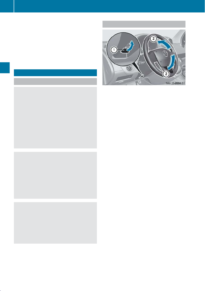
Steering wheel
72
X
Make sure the engine is running.
X
To switch on: press button =.
Indicator lamp ; lights up.
X
To switch off: press button :.
Indicator lamp ; goes out.
The seat heating does not switch off auto-
i
matically.
Steering wheel
Important safety notes
Adjusting the steering wheel
WARNING
G
You could lose control of the vehicle while
driving if you:
R
adjust the driver's seat, steering wheel or
mirrors
R
fasten the seat belt
There is a risk of an accident.
Adjust the
driver's seat, head restraint, steering wheel and mirrors and fasten your seat
belt before starting the engine.
WARNING
G
The steering wheel may move unexpectedly if
you adjust it while driving. This could cause
Seats, steering wheel and mirrors
you to lose control of the vehicle. There is a
risk of an accident.
Make sure that the steering wheel is locked
before driving off. Never unlock the steering
wheel when the vehicle is in motion.
WARNING
G
Children could become trapped by the steering wheel if they adjust it. There is a risk of
injury.
When leaving
the vehicle, always take the key
with you and lock the vehicle. Never leave
children unattended in the vehicle.
X
Fold release lever : up completely.
The steering column is released.
X
Set desired steering wheel height ;.
X
Fold release lever : down completely.
The steering column is locked.
X
Check whether the steering column is locked.
do
this, try to push the steering wheel up or
To
down.
Page 75

Problems with the steering wheel
Mirrors
73
Problem
The steering wheel
remains locked.
Possible causes/consequences and M Solutions
The steering wheel lock is enabled.
X
Move the key and steering wheel slightly (Y page 103
The steering wheel lock is disabled. The steering wheel is unlocked.
The vehicle is hard to
steer.
The power steering may be overheated.
X
Have the power steering checked at a qualified specialist workshop.
Mirrors
Rear-view mirror
Rear-view mirror with manual anti-dazzle function
X
Anti-dazzle mode:
forwards or back.
flick
anti-dazzle switch :
Rear-view mirror with automatic antidazzle function
WARNING
G
Electrolyte may escape if the glass of an automatic anti-dazzle mirror breaks. Electrolyte is
harmful and causes irritation. It must not
come into contact with your skin, eyes, respiratory organs or clothing or be swallowed.
There is a risk of injury.
).
If you come into contact with electrolyte,
observe the following:
R
immediately rinse
off electrolyte from your
skin with water.
R
immediately and thoroughly rinse electrolyte out of eyes using clean water.
R
if electrolyte is swallowed, immediately
rinse out your mouth thoroughly. Do not
induce vomiting.
R
if electrolyte comes into contact with skin
or eyes or is swallowed, seek medical attention immediately.
R
immediately change out of clothing that has
been in contact with electrolyte.
R
if an allergic reaction occurs, seek medical
attention immediately.
The anti-dazzle function of the rear-view mirror
is activated automatically if:
R
the ignition is switched on
R
incident light from headlamps falls on the
sensor in the rear-view mirror.
The rear-view mirror's automatic anti-dazzle
function does not operate if reverse gear is
engaged or the interior lighting is switched on.
Exterior mirrors
Important safety notes
Seats, steering wheel and mirrors
WARNING
G
The exterior mirrors reduce the size of the
image. Objects visible in the mirrors are
closer than they appear. You could misjudge
the distance from road users driving behind
Z
Page 76

Mirrors
74
you when changing lanes, for instance. There
is a risk of an accident.
You should therefore always look over your
shoulder to determine the actual distance
from road users driving behind you.
Adjusting the exterior mirrors electrically
X
Turn the key to position 2 in the ignition lock
Y page 103).
(
X
Turn control : to position 1 for the lefthand mirror or position 3 for the right-hand
mirror.
X
Press the top, bottom, left or right section of
control :
correct position.
Seats, steering wheel and mirrors
You should have a good view of traffic condi-
until the exterior mirror is in the
tions.
X
Turn the control to position 2.
this
position, the setting of the exterior mir-
In
ror is fixed and can no longer be changed.
Adjusting the exterior mirrors manually
With electrically heated and adjustable exterior
mirrors: when
window heating is switched on, the exterior mirrors are heated.
the engine is running and the rear
X
Move lever : until
the exterior mirror is in the
correct position.
You should have a good view of traffic conditions.
Folding the exterior mirrors in or out
electrically
X
Turn the key to position 2 in the ignition lock
page 103).
(Y
X
To fold in: turn the control to position 3.
Both exterior mirrors fold in.
X
To fold out: turn the control to position 1
2.
Both exterior mirrors fold out.
Make sure that the exterior mirrors are
i
always folded out fully while driving. They
could otherwise vibrate.
or
Page 77

Disengaged exterior mirrors
If an exterior mirror has been forcibly disengaged, proceed as follows:
X
Move the exterior mirror into the correct position manually.
or
X
Fold in the exterior mirror electrically
(Y page 74
The mirror housing is engaged again and you
can adjust the exterior mirrors as usual
(Y page 73).
If you want to fold in a disengaged exterior
i
mirror electrically, you may have to use the
fold-in procedure repeatedly until it folds in.
).
Mirrors
75
Seats, steering wheel and mirrors
Z
Page 78
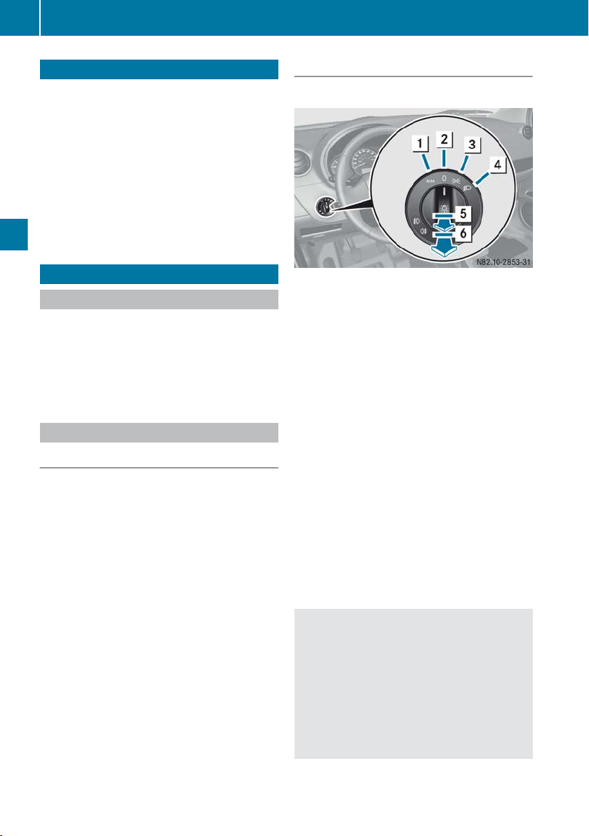
Exterior lighting
76
Useful information
These Operating Instructions describe all
i
models as well as standard and optional
equipment of your vehicle that was available
time of going to print. Country-specific
at the
variations are possible. Note that your vehicle
may not be fitted with all of the described
functions. This also applies to safety-relevant
systems and functions.
Read the information on qualified specialist
i
workshops (Y page 18).
Exterior lighting
Important safety notes
For reasons of safety, Mercedes-Benz recommends that
even during the daytime. There may be differences in operation due to legal requirements
and voluntary recommendations in some countries.
you drive with the lights switched on
Setting the exterior lighting
Setting options
Exterior lighting can be set using the:
Lights and windscreen wipers
R
light switch
R
headlamp range control (
R
combination switch (Y page 78)
Y page 77)
Light switch
Operation
1Ã
Automatic headlamp mode, controlled
by the light sensor/daytime driving
lights
2$
3T
Lights off/daytime driving lights
Side lamps, licence plate and instru-
ment cluster lighting
4L
5N
6R
Dipped-beam/main-beam headlamps
Front foglamps
Rear foglamp
If you hear a warning tone when you leave the
vehicle, the lights may still be switched on.
X
Turn the light switch to $ or Ã.
or
X
If the rear foglamp is switched on: press the
light switch in to the stop.
The exterior lighting (except the side lamps)
switches off automatically if you:
R
remove the key from the ignition lock
R
open
driver's door with the key in position
the
1
Automatic headlamp mode
WARNING
G
When the light switch is set to Ã, the
dipped-beam
headlamps
may not be switched
on automatically if there is fog, snow or other
causes of poor visibility due to the weather
conditions such as spray. There is a risk of an
accident.
In such situations, turn the light switch to
L.
Page 79

Exterior lighting
77
Automatic headlamp mode is only a driving aid.
responsible for the vehicle lighting at all
You are
times.
à is the preferred light switch setting. The
light setting is automatically selected according
to the brightness of the ambient light (exception: poor visibility due to weather conditions
such as fog, snow or spray):
R
Key in position 1 in the ignition lock: the side
lamps are switched on or off automatically
depending on the brightness of the ambient
light.
R
When the engine is on: depending on the
ambient light conditions, the daytime driving
lights or the side lamps and dipped-beam
headlamps are switched on or off automatically.
To switch on automatic headlamp mode:
X
turn the light switch to Ã.
The daytime driving lights improve the visibility
of your vehicle during the day.
When
dipped-beam headlamps are switched
the
on, the green L indicator lamp in the instrument cluster lights up and the daytime driving
lights switch off.
Dipped-beam headlamps
Even if the light sensor does not detect that it is
dark, the side lamps and dipped-beam headlamps switch on when the key is inserted into
the ignition lock and the light switch is set to the
L position. This is a particularly useful function in the event of rain and fog.
To switch on the dipped-beam headlamps:
X
turn the key to position 2 in the ignition lock
or start the engine.
X
Turn the light switch to the L position.
The green L indicator lamp in the instrument cluster lights up.
X
Pull the light switch out to the first detent.
The green N indicator lamp on the light
switch lights up.
X
To switch off the front foglamps: press
the
light switch in as far as it will go.
The green N indicator lamp on the light
switch goes out.
Rear foglamp
The rear
foglamp improves visibility of your vehicle for the traffic behind in the event of heavy
fog. Please take note of the country-specific
regulations for the use of rear foglamps.
X
To switch on the rear foglamp: start the
engine.
X
Turn the light switch to L or T. When
the light switch is set to Ã, you cannot
switch on the rear foglamp.
X
Pull the light switch out to the second detent.
The yellow R indicator lamp on the light
switch lights up.
X
To switch off the rear foglamp: press the
light switch in as far as it will go.
The yellow R indicator lamp on the light
switch goes out.
Side lamps
X
To switch on: turn the light switch to the
T position.
Adjusting the headlamp range (halogen
headlamps)
Lights and windscreen wipers
Front foglamps
Front foglamps help you to see and be seen in
conditions of poor visibility due to fog or precipitation. They can be operated with the side
lamps, or with the side lamps and the dippedbeam headlamps.
X
To switch on the front foglamps: start the
engine.
X
Turn the light switch to L or T. If the
light switch
is set to Ã, you cannot switch
on the front foglamps.
Headlamp range control : allows
you to adjust
the cone of light from the headlamps to suit the
vehicle load. The cone of light from the headlamps changes if seats are occupied or if the
load compartment is being loaded or unloaded.
This can impair visibility and dazzle oncoming
traffic.
Z
Page 80
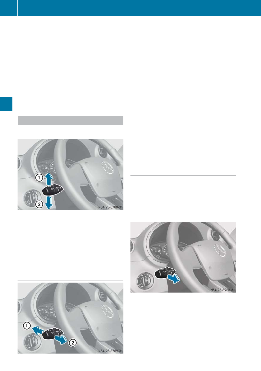
Exterior lighting
78
X
Turn the key to position 2 in the ignition lock
or start the engine.
X
Turn the light switch to the
X
Turn headlamp range control : downwards
L position.
to position the dipped beams lower and
upwards to position them higher.
X
Turn headlamp range control : to
position 0
or 1 for an unladen vehicle and to positions 1
to 4 for a partially or fully laden vehicle.
The road ahead should be lit up for 40 mto
100 m and the dipped-beam headlamps
should not dazzle oncoming traffic.
Combination switch
Turn signal
X
To indicate: press the combination switch
Lights and windscreen wipers
beyond the pressure point in the direction of
arrow : or ;.
X
Brief turn signals: briefly press the combination switch in the direction of arrow :
or ;.
The turn signal flashes three times.
To switch on the main-beam headlamps:
X
start the engine.
X
Turn the light switch to L or Ã.
X
Press the combination switch beyond the
pressure point in the direction of arrow :.
In the à position, the main-beam head-
are
lamps
only switched on when it is dark and
the engine is running.
The K indicator lamp in the instrument
cluster lights up when the main-beam headlamps are switched on.
To switch off the main-beam headlamps:
X
move the
combination switch back to its nor-
mal position.
The K indicator lamp in the instrument
cluster goes out.
X
To switch on the headlamp flasher: turn
to position 1 or 2 in the ignition lock or
the key
start the engine.
X
Pull the combination switch in the direction of
arrow ;.
Follow-me-home function
This function can be used to briefly switch on the
dipped-beam headlamps, e.g. when opening a
garage door. If the function is activated once,
the dipped-beam headlamps remain switched
on for 30 seconds after leaving the vehicle. You
can activate the function up to four times to give
a total operating time of 2 minutes.
Main-beam headlamps and headlamp
flasher
X
To activate: pull the combination switch in
the direction of the arrow.
The dipped-beam headlamps switch on for
approx. 30 seconds.
Page 81

Interior lighting
79
Notes on driving abroad
Switching to symmetrical dipped beams
when driving abroad: when driving in coun-
which traffic drives on the opposite side
tries in
of the road to the country where the vehicle is
registered, the headlamps should be switched
to symmetrical dipped beam. This prevents
oncoming traffic from being dazzled. Symmetrical beams illuminate less of the edge of the carriageway in terms of height and distance.
Have the headlamps adjusted at a qualified specialist workshop before you cross the border,
but as close to it as possible.
Switching to asymmetrical dipped beams
when returning from abroad: have the head-
lamps adjusted at a qualified specialist workshop after crossing over the border again, but as
close to it as possible.
Hazard warning lamps
Headlamps misted up on the inside
The headlamps may mist up on the inside if
there is high atmospheric humidity.
X
Drive with the headlamps switched on.
The level of moisture diminishes, depending
on the length of the journey and the weather
conditions (humidity and temperature).
If the level of moisture does not diminish:
X
Have the headlamps checked at a qualified
specialist workshop.
Interior lighting
Interior lighting overview
Front interior lighting
To switch on the hazard warning lamps:
X
press button :.
All turn signals flash.
To switch off the hazard warning lamps:
X
press button :.
The hazard warning lamps automatically switch
on if:
R
an airbag is deployed.
R
the vehicle decelerates rapidly from a speed
of more
than 70 km/h and comes to a stand-
still.
The hazard warning lamps switch off automatically if the vehicle reaches a speed of over
10 km/h again after a full brake application.
The hazard warning lamps still operate if the
i
ignition is switched off.
Front overhead control panel
:
To switch off the front interior lighting
;
Automatic light control
=
To switch on the front interior lighting
?
To switch off the reading lamp in the codriver's area
A
To switch on the reading lamp in the co-driver's area
Lights and windscreen wipers
Z
Page 82

Replacing bulbs
80
Reading lamp (depending on vehicle)
:
To switch the reading lamp on/off
Switching on the interior lighting when the door
is open: if the respective door is closed correctly, the interior lighting will switch off.
Load compartment lights
Lights and windscreen wipers
Depending on vehicle
;
To switch the load compartment lights
on/off
Interior light in the rear compartment
Depending on the vehicle, the interior light: for
the third
roof lining.
X
X
row of seats is located overhead on the
To switch on the interior light: press
switch =.
To switch off the interior light: press
switch ;.
rocker
rocker
Interior lighting control
If the
doors are unlocked using the remote control, the timer for the interior lighting will be triggered. The timer is reset when the front or rear
door is opened.
The front interior lights and the lights in the load
compartment gradually switch off.
The interior lighting timer switches off when:
R
a door remains open (after 15 minutes)
R
all doors are closed (after 15 seconds or
5 minutes depending on the vehicle)
R
switching on the ignition.
Side sliding door (depending on vehicle)
=
To switch the lighting on/off
Switching on the lighting when the side sliding
door is open: if the respective door is closed
correctly, the lighting will switch off.
Replacing bulbs
Important safety notes
WARNING
G
Bulbs, lamps and plug connectors can
become very
bulb, you could burn yourself on these components. There is a risk of injury.
Allow these components to cool down before
replacing the bulb.
hot during use. When replacing a
Page 83

Do not use a bulb that has been dropped or that
has scratches on its glass tube.
The bulb could explode if:
R
you touch it
R
it is hot
R
you drop it
R
you scratch or score it.
Only operate bulbs in closed lamps which have
been designed for this purpose. Only fit spare
bulbs of the same type and the specified voltage.
Marks on the glass tube shorten the operating
a bulb. Do not hold the glass bulb with your
life of
bare hands. If necessary, clean the glass bulb
with alcohol or spirit while it is cold and wipe
with a lint-free cloth.
Protect the bulbs against moisture when in use.
Do not allow the bulbs to come in contact with
liquids.
Replace only the bulbs listed (Y page 81).
Have bulbs that you cannot replace yourself
replaced at a qualified specialist workshop.
If you require assistance changing bulbs, consult a qualified specialist workshop.
If the new bulb still does not light up, consult a
qualified specialist workshop.
Bulbs and lamps are an important aspect of
vehicle safety. You must therefore make sure
that these function correctly at all times. Have
the headlamp setting checked regularly.
Replacing bulbs – Overview of bulb types
The following
replaced:
lamps with their bulb types can be
Replacing bulbs
Front bulbs
:
Side turn signals: WY 5W
;
Turn signals: PY 21 W
=
Dipped-beam/main-beam headlamps:
H4 60/55 W
?
Side lamps: P 21 5W
Rear bulbs
:
Third brake lamp: W 16W
;
Tail/brake lamp: P 21/5W
=
Reversing lamp: P 21 W
?
Turn signals: PY 21 W
A
Licence plate lamp: W 5W
Interior lighting:
R
Front interior light, left: W 5W
R
Front interior light, right: W 5W
R
Reading lamp: W 6W
R
Load compartment light: W 5W or W 6W
(depending on vehicle)
R
Illumination of side sliding door: W 6W
(depending on vehicle)
81
Lights and windscreen wipers
Z
Page 84

Replacing bulbs
82
Changing the front bulbs
Dipped-beam/main-beam headlamps
X
Switch off the lighting system.
X
Open the bonnet.
X
Push down lever : and unclip the cover.
X
Remove the cover.
Side lamps
X
Switch off the lighting system.
X
Open the bonnet.
X
Push down lever : and unclip the cover.
X
Remove the cover.
Lights and windscreen wipers
X
Hold bulb = and pull out the connector.
X
Release the clips and pull out bulb =.
X
Insert the new bulb and insert the connector.
X
Engage the clips.
X
Attach the cover, ensuring that lugs ;
bottom of the cover are inserted correctly.
X
Clip in the cover.
on
the
X
Remove the connector for the dipped/mainbeam headlamp.
X
Remove bulb holder =.
X
Remove the bulb.
X
Insert the new bulb and clip bulb holder =
into place.
X
Insert the connector for the dipped/mainbeam headlamp.
X
Attach the cover, ensuring that lugs ;
bottom of the cover are inserted correctly.
X
Clip in the cover.
on
the
Page 85

Turn signal
X
Switch off the lighting system.
X
Open the bonnet.
X
Turn bulb holder : anti-clockwise and
remove it.
X
Turn the bulb anti-clockwise, applying slight
pressure,
X
Insert the new bulb into bulb holder : and
and
remove it from bulb holder :.
turn it clockwise.
X
Insert bulb holder : and turn it clockwise.
Turn signals
Replacing bulbs
X
Turn bulb holder ; 90° anti-clockwise.
X
Remove the bulb.
X
Insert the new bulb into bulb holder ;.
X
Tighten bulb holder ;.
X
Insert turn signal :.
Front foglamps/daytime driving lights
Due to the installation position of front foglamps/daytime driving lights :, MercedesBenz recommends that you have the bulbs
changed at a qualified specialist workshop (the
removal of the bumper is necessary, for example).
83
X
Using a flat tool, push turn signal : forwards
and lever it out.
Replacing the rear bulbs
Tail lamp
X
Switch off the lighting system.
X
Open the rear door or the tailgate.
X
Undo 3 screws : on
key.
X
Using a suitable tool, carefully lever out the
tail lamp.
tail lamp ; using a Torx
Lights and windscreen wipers
Z
Page 86

Replacing bulbs
84
X
Press the release catch and pull out connector =.
X
Unclip catches ? on bulb holder A.
Bulb holder
B
Tail/brake lamp
C
Reversing lamp
Lights and windscreen wipers
D
Turn signal
X
Pull out the respective bulb.
X
Insert the respective new bulb.
X
Clip catches ? onto bulb holder A.
X
Insert connector =.
X
Tighten 3 screws : on tail lamp ; using a
Torx key.
Third brake lamp
The third brake lamp is:
R
R
centre above the rear window (vehicles
in the
with tailgate)
above the rear window on the left door (vehicles with rear door)
: Third brake lamp (vehicles with rear doors)
X
Switch off the lighting system.
Vehicles with rear door
X
Remove both plastic caps :
X
Use a screwdriver, for instance, to press
from
the inside.
metal clips ; into the bracket.
The brake lamp disengages.
X
Remove bulb = from the outside and insert
the new bulb.
X
Push the bulb back in.
X
Make sure the brake lamp correctly engages.
X
Attach both plastic caps :.
Page 87

Rear foglamp
Due to the installation position of front foglamps :, Mercedes-Benz recommends that
you have the bulbs changed at a qualified specialist workshop
(removal of the bumper is nec-
essary, for example).
Licence plate illumination
Replacing bulbs
X
Replace the bulb.
X
Insert lamp lens = into the licence plate
lamp.
X
Insert the connector.
X
Insert bulb holder : and clip it into place.
Replacing the interior lighting
Interior lighting
Front interior lighting
85
X
Switch off the lights.
X
Unclip, release and remove bulb holder :.
X
Press the catch and pull out the connector.
X
Using a suitable tool, release catch ;
lens = on the left and right.
X
Remove lamp lens =.
of
Example: rear interior lighting
X
Lift off lamp lens : (arrow) using a flat tool
such as a screwdriver.
X
Remove lamp lens :.
lamp
Lights and windscreen wipers
Z
Page 88
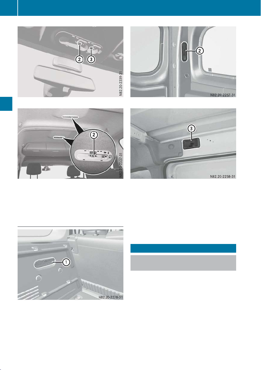
Windscreen wipers
86
Front interior lighting
Example: rear interior lighting
X
Pull bulb ;
X
Insert new bulb into the holder.
X
Replace lamp lens :.
Lights and windscreen wipers
Load compartment lights
Example
or =
down and out of the holder.
Example
Example: side sliding door
X
Lift off lamp lens :, ;
or =
using a flat tool
such as a screwdriver.
X
Remove lamp lens :, ; or =.
X
Pull bulb down and out of the holder.
X
Insert new bulb into the holder.
X
Replace lamp lens :, ; or =.
Windscreen wipers
Switching the windscreen wipers on/ off
Do not
!
the windscreen is dry, as this could damage
the wiper blades. Moreover, dust that has collected on the windscreen can scratch the
glass if wiping takes place when the windscreen is dry.
If it is necessary to switch on the windscreen
wipers in dry weather conditions, always
operate them using washer fluid.
!
the windscreen after the vehicle has been
washed in an automatic car wash, this may be
operate the windscreen wipers when
If the windscreen wipers leave smears on
Page 89

Windscreen wipers
87
due to wax or other residue. Clean the windscreen with washer fluid after an automatic
car wash.
Intermittent wiping
!
with rain sensor: due to
optical influences and the windscreen becoming dirty in dry weather conditions, the windscreen wipers may be activated inadvertently.
This could damage the windscreen wiper
blades or scratch the windscreen.
For this reason, you should always switch off
the windscreen wipers in dry weather.
Combination switch
1
$ Windscreen wipers off
2
Ä Intermittent wipe
3
° Continuous wipe, slow
4
¯ Continuous wipe, fast
A
í Single wipe/î To wipe with
washer fluid
X
Turn the key to position 2
Y page 103).
(
X
Turn the combination switch to the appropri-
in the ignition lock
ate position.
Vehicles with rain sensor: in the Ä posi-
tion, the appropriate wiping frequency is set
automatically according to the intensity of the
rain.
All vehicles: the windscreen will no longer be
wiped properly
if the wiper blades are worn. This
may prevent you from observing the traffic conditions.
Switching the rear window wiper on/ off
Combination switch
:
è Rear window wiper switch
2
ô To wipe with washer fluid
3
I To switch on intermittent wiping
4
0 To switch off intermittent wiping
5
ô To wipe with washer fluid
X
Turn the key to position 2
Y page 103).
(
X
Turn switch : on the combination switch to
in the ignition lock
the appropriate position.
The rear window wiper switches on auto-
i
matically in intermittent mode if you engage
reverse gear
while the windscreen wipers are
on.
Replacing the wiper blades
Important safety notes
WARNING
G
If the windscreen wipers begin to move while
you are
changing the wiper blades, you can be
trapped by the wiper arm. There is a risk of
injury.
Always switch off the windscreen wipers and
ignition before changing the wiper blades.
Lights and windscreen wipers
Never open the bonnet/tailgate if a wiper
!
arm is folded away from the windscreen/rear
window.
Never fold a windscreen wiper arm without a
wiper blade back onto the windscreen/rear
window.
Z
Page 90

Windscreen wipers
88
Hold the windscreen wiper arm firmly when
you change
the wiper blade. If you release the
wiper arm without a wiper blade and it falls
onto the windscreen/rear window, the windscreen/rear window may be damaged by the
force of the impact.
Mercedes-Benz recommends that you have
the wiper blades changed at a qualified specialist workshop.
To avoid damaging the windscreen wiper
!
blades, make sure that you touch only the
wiper arm of the windscreen wiper.
Depending on the equipment level of your vehicle, there are two variants of wiper blade; these
are fitted and removed in different ways. Based
on the diagrams, check which system is fitted in
your vehicle.
Replacing the windscreen wiper blades
(variant 1)
Removing the wiper blades
X
Remove the key from the ignition lock.
X
Raise the wiper arm and hold it in that position.
Lights and windscreen wipers
Assembling the wiper blades
X
Position new wiper blade : with recess B
on lug A.
X
Fold wiper blade : in the direction of
arrow = onto the wiper arm, until retaining
clips ; engage in bracket ?.
X
Make sure that wiper blade :
is seated cor-
rectly.
X
Guide the wiper arm onto the windscreen
again.
Replacing
the windscreen wiper blades
(variant 2)
Removing the wiper blades
X
Remove the key from the ignition lock.
X
Raise the wiper arm and hold it in that position.
X
Press both release clips ;.
X
Fold wiper blade : in the direction of
arrow = away from wiper arm ?.
X
Remove wiper blade : in the direction of
arrow A.
X
Fold release lever A in the direction of
arrow ? and
release wiper blade : from the
retainer.
X
Remove wiper blade : in the direction of
arrow ; from wiper arm =.
Page 91

Windscreen wipers
89
Assembling the wiper blades
X
Position new wiper blade : onto wiper
arm = and slide
in the direction of arrow ;
through the recess for release lever A.
X
Fold release lever A in the direction of
arrow ?.
X
Make sure that wiper blade :
is seated cor-
rectly.
X
Guide wiper arm =
onto the windscreen
again.
Replacing the rear window wiper blade
Removing the wiper blade (vehicles with
rear door)
Removing the wiper blade (vehicles with
tailgate)
X
Remove the key from the ignition lock.
X
Fold the wiper arm away from the rear window.
X
Position wiper blade : at
a right angle to the
wiper arm.
X
Unclip wiper blade : in the direction of the
arrow, using a fair amount of pressure to do
so.
To assemble, follow the instructions in reverse
order. Make sure that the wiper blade is correctly engaged.
X
Remove the key from the ignition lock.
X
Fold wiper arm = away
X
Position wiper blade : at a right angle to
from the rear window.
wiper arm =.
X
Hold wiper arm = and press it onto spring
clip ;.
X
Remove wiper blade :
in
the direction of the
arrow.
To assemble, follow the instructions in reverse
order. Make sure that the wiper blade is correctly engaged.
Lights and windscreen wipers
Z
Page 92

Windscreen wipers
90
Problems with the windscreen wipers
Problem
The windscreen wiper
jams.
Possible causes/consequences and M Solutions
Leaves or snow, for example, hinder the movement of the windscreen
wiper or
the wiper blades are frozen to the front windscreen. The wiper
motor has switched off.
X
For safety reasons, you should remove the key from the ignition
lock.
X
Remove the cause of the obstruction.
X
Switch on the windscreen wipers again.
The windscreen wiper
does not stop.
There is a malfunction in the windscreen wiper drive.
X
Have the windscreen wipers checked at a qualified specialist workshop.
The windscreen wiper
does not move at all.
There is a malfunction in the windscreen wiper drive.
X
Select another wiper speed on the combination switch.
X
Have the windscreen wipers checked at a qualified specialist workshop.
The washer fluid coming
from the
spray nozzles is
not meeting the centre
The spray nozzles are misaligned.
X
Have the spray nozzles checked at a qualified specialist workshop.
of the windscreen.
Lights and windscreen wipers
Page 93

Overview of climate control systems
91
Useful information
These Operating Instructions describe all
i
models as well as standard and optional
equipment of your vehicle that was available
time of going to print. Country-specific
at the
variations are possible. Note that your vehicle
may not be fitted with all of the described
functions. This also applies to safety-relevant
systems and functions.
Read the information on qualified specialist
i
workshops (Y page 18).
Overview of climate control systems
Important safety notes
Observe the recommended settings on the following pages. Otherwise, the windows could
mist up.
To prevent the windows from misting up:
R
only switch off climate control briefly
R
only switch on air-recirculation mode briefly
R
air-conditioning system/TEMPMATIC airconditioning system: activate the "Cooling
with air dehumidification" function
R
switch on the demisting function briefly, if
necessary
The air-conditioning system and the semi-automatically controlled TEMPMATIC air-conditioning system
the vehicle interior. They also filter undesirable
substances from the air.
The air-conditioning system and the semi-automatically controlled TEMPMATIC air-conditioning system are only operational when the engine
is running. They only function optimally if the
side windows and the roof hatch are closed.
i
warm weather. This will speed up the cooling
process and the desired interior temperature
will be reached more quickly.
i
particles and pollen. A clogged filter reduces
the amount of air supplied to the vehicle interior. For this reason, you should always
observe the interval for replacing the filter,
which is specified in the Maintenance Booklet. As it depends on environmental conditions, e.g. heavy air pollution, the interval may
set the temperature and humidity of
Ventilate the vehicle for a brief period during
The integrated filter can filter out most dust
be shorter than that stated in the Maintenance Booklet.
Climate control
Page 94

Overview of climate control systems
92
Heating control panel
:
Switches air-recirculation mode on/off (Y page 100)
;
Sets the airflow (Y page
=
Sets the temperature
?
Turns rear window heating on/off (depending on the vehicle) (Y page
Turns mirror heating on/off (depending on the vehicle)
A
Sets the air distribution (Y page 97
Climate control
97)
(Y page
96
)
)
98
)
Notes on using the heating
Heating
Below, you can find a number of notes and recommendations to
mally.
R
Switch on the air-conditioning system by turning control knob ; clockwise to the desired
position (except position 0).
R
Only change the temperature in small increments.
To increase or decrease the temperature, turn
control knob = in a clockwise or anti-clockwise direction.
R
Recommendation to avoid misting of the
windows in the event of low outside temperatures or rain: switch on the air distribu-
tion z. Deactivate air-recirculation mode
ø. Set airflow control ; to level 3 or 4.
R
Recommendation for rapid heating of the
vehicle interior: briefly set airflow control
knob ; to position 3 or 4.
help you use the heating opti-
R
Recommendation for a constant vehicle
interior temperature: set airflow control
knob ; to position 1 or 2.
R
Recommended air
distribution setting for
winter months: select setting a.
Recommended air distribution setting for
summer months: select setting S.
R
Only use the demisting function briefly, until
the windscreen is clear again.
R
Only use air-recirculation mode briefly, e.g. if
there are unpleasant outside odours or when
in a tunnel. The windows could otherwise mist
up as no fresh air is drawn into the vehicle in
air-recirculation mode.
ECO start/stop function
During automatic engine switch-off of the ECO
start/stop function,
reduced output. If you require full heater output,
the ECO start/stop function can be deactivated
by pressing the ECO OFF button (Y page 105).
the heater only operates at
Page 95

Overview of climate control systems
Control panel for the air-conditioning system
:
Switches air-recirculation mode on/off (Y page 100)
;
Sets the airflow (Y page
=
Switches cooling with air dehumidification on/off(Y
?
Sets the temperature (Y page
A
Turns rear window heating on/off (depending on the vehicle) (Y page
Turns mirror heating on/off (depending on the vehicle)
B
Sets the air distribution (
97)
96
Y page 97
page
95
)
)
93
)
98)
Climate control
Notes on using the air conditioning system
Air-conditioning system
Below, you can find a number of notes and recommendations to help you use the air-conditioning system optimally.
R
Switch on
ing control knob ; clockwise to the desired
position (except position 0).
R
Only change the temperature in small increments.
To increase or decrease the temperature, turn
control knob ? in a clockwise or anti-clockwise direction.
R
Recommendation to avoid misting of the
windows in the event of low outside temperatures or rain: switch on the air distribu-
tion z. Deactivate air-recirculation mode
ø. Set airflow control ; to level 3 or 4.
R
Recommendation for rapid cooling or
heating of the vehicle interior: briefly set
airflow control knob ; to position 3 or 4.
the air-conditioning system by turn-
R
Recommendation for a constant vehicle
interior temperature: set airflow control
knob ; to position 1 or 2.
R
Recommended air
distribution setting for
winter months: select setting a.
Recommended air distribution setting for
summer months: select setting S.
R
Only use the demisting function briefly, until
the windscreen is clear again.
R
Only use air-recirculation mode briefly, e.g. if
there are unpleasant outside odours or when
in a tunnel. The windows could otherwise mist
up as no fresh air is drawn into the vehicle in
air-recirculation mode.
ECO start/stop function
During automatic engine switch-off of the ECO
start/stop function,
only operates at a reduced capacity. If you
require full climate control capacity, the ECO
start/stop function can be deactivated by
pressing the ECO OFF button (Y page 105).
the climate control system
Page 96

Overview of climate control systems
94
Control panel for the TEMPMATIC air-conditioning system
:
Activates/deactivates air-recirculation mode (Y page 100)
;
Defrosts the windscreen (Y page
=
Switches the cooling with air dehumidification function on/off (
?
Display
A
Regulates climate control automatically
B
Decreases the airflow
Climate control
C
Sets the air distribution (Y page
D
Increases the airflow (Y page
E
Sets the air distribution (Y page
F
Sets the temperature (
G
Turns rear window heating on/off (depending on the vehicle) (Y page
(Y page
Y page
Turns mirror heating on/off (depending on the vehicle)
97
97
96
)
97
)
97)
)
97)
)
(Y page
96)
Y page
98
95)
)
Notes on using the TEMPMATIC airconditioning system
TEMPMATIC air-conditioning system
Below, you can find a number of notes and recommendations to help you use the semi-automatically controlled TEMPMATIC air-conditioning system optimally.
R
Preferably switch
à button. AUTO appears in the display.
R
Set the temperature to 22 †.
R
Only use the demisting function briefly, until
the windscreen is clear again.
R
Only use air-recirculation mode briefly, e.g. if
there are unpleasant outside odours or when
in a tunnel. The windows could otherwise mist
on climate control using the
up as no fresh air is drawn into the vehicle in
air-recirculation mode.
ECO start/stop function
During automatic engine switch-off of the ECO
start/stop function,
only operates at a reduced capacity. If you
require the full climate control output, you can
switch off the ECO start/stop function by pressing the ECO button (Y page 105).
the climate control system
Page 97

Operating the climate control system
95
Operating the climate control system
Activating/deactivating the climate control
General notes
When climate control is switched off, the air
supply and
air circulation are also switched off.
The windows could mist up. Only switch off climate control briefly.
Switching on/off
Heating/air-conditioning system
X
Turn the key to position 2 in the ignition lock
(
Y page 103).
X
To switch on: turn control knob ; for the
airflow clockwise to the desired position
(except position 0) (
X
To switch off: turn control knob ; for the
Y page 103).
airflow anti-clockwise to position 0
(Y page 103
).
TEMPMATIC air-conditioning system
X
Turn the key to position 2 in the ignition lock
(
Y page 103).
X
To activate: press the ó button.
One or
several segments of the airflow symbol
are shown as filled in the display.
X
To switch off: press
the ô button until the
airflow switches off.
No segment of the airflow symbol is shown as
filled in the display.
Switching the cooling with air dehumidification function on/off
General notes
The "Cooling with air dehumidification" function
is only available for the air-conditioning system
and the semi-automatically controlled TEMPMATIC air-conditioning system.
If you
deactivate the "Cooling with air dehumidification" function, the air inside the vehicle will
not be cooled in warmer weather conditions.
The air inside the vehicle will not be dehumidified either. The windows could mist up more
quickly. Therefore, only switch off the "Cooling
with air dehumidification" function briefly.
The "Cooling with air dehumidification" function
available when the engine is running. The
is only
air inside the vehicle is cooled and dehumidified
according to the temperature selected.
The "Cooling with air dehumidification" function
does not work at low outside temperatures.
Condensation may appear on the underside of
the vehicle when in cooling mode. This is normal
and not a sign that there is a malfunction.
Switching on/off
Air-conditioning system
X
Start the engine.
X
Turn control knob ; for
the airflow clockwise
to position 1 or higher (Y page 97).
X
To activate: press the ¿ button.
The indicator lamp in the ¿ button lights
up.
X
To deactivate: press the ¿ button.
The indicator lamp in the ¿ button goes
out.
TEMPMATIC air-conditioning system
If automatic
mode is activated, the cooling with
air dehumidification function is switched on and
off depending on the outside temperature. You
can also switch cooling with air dehumidification on and off manually.
X
Start the engine.
X
To deactivate manually: press the Â
button.
AUTO disappears from the display, and AC OFF
appears. The cooling with air dehumidification function and automatic mode are
switched off.
X
To switch on manually: press the Â
but-
ton.
AUTO disappears from the display, and AC OFF
appears. The cooling with air dehumidification function and automatic mode are
switched on.
Climate control
Page 98

Operating the climate control system
96
Problems with the "Cooling with air dehumidification" function
Problem
Cooling with air dehumidification cannot be
switched on or there is
air coming out of
no cold
the air vents.
Possible causes/consequences and M Solutions
The buttons and control knobs are in the wrong position.
X
Turn the buttons and control knobs to the correct position.
There is a problem with the fuses.
X
Check the fuses.
If this does not help:
X
Visit a qualified specialist workshop.
Regulating climate control automatically
General notes
This function is only available for the semi-automatically controlled TEMPMATIC air-conditioning system.
In automatic
mode, the set temperature is automatically kept constant. The system automatically regulates the temperature of the dis-
Climate control
pensed air, the airflow and the air distribution.
To maintain a constant temperature, the TEMP-
MATIC air-conditioning system automatically
switches on and off.
Automatic mode only operates while the engine
is running.
Automatic mode is the recommended operating
mode since it guarantees a pleasant temperature in the vehicle and good visibility.
Switching on/off
X
Start the engine.
X
To activate: press the à button.
AUTO appears in the display. The airflow and
air distribution are controlled automatically.
X
To switch to manual mode: press the Ã
button again.
or
X
Press the ó
or
X
Press the M or O button.
AUTO disappears from
air distribution and airflow are deactivated.
or ô button.
the display. Automatic
bol for the air distribution or the airflow is
shown in the display. All other functions will
continue to be controlled automatically.
Setting the temperature
Heating/air-conditioning system
X
Turn the key to position 2 in the ignition lock
Y page 103).
(
X
Turn control knob ; for
the airflow clockwise
to position 1 or higher (Y page 97).
X
To increase (heating): turn control knob =
for the temperature clockwise (Y
X
To increase (air-conditioning system): turn
page 92).
control knob ? for the temperature clockwise (
Y page 93).
X
To reduce (heating): turn control
knob = for
the temperature anti-clockwise (Y page 92).
X
To reduce (air-conditioning system): turn
control knob ? for the temperature anticlockwise (Y page 93
).
Only change the temperature in small increments.
TEMPMATIC air-conditioning system
X
Turn the key to position 2
(Y
page 103).
X
To increase/reduce: press on right-hand or
left-hand temperature
Only change the temperature in small increments. Start at 22 †.
The display shows the selected temperature.
in the ignition lock
button F (Y page 94).
If you
i
change one of the functions manually,
AUTO will disappear from the display. The sym-
Page 99

Operating the climate control system
97
Setting the air distribution
Air distribution settings
Heating/air-conditioning system
z
Directs air through the demister vents
a
Directs air through the demister and footwell vents
O
Directs air through the footwell vents
S
Directs air through the centre, side and
footwell vents
P
Directs the airflow through the centre
and side air vents
Recommended air distribution setting
i
for winter months: select setting a.
Recommended
distribution setting for
air
summer months: select setting S.
TEMPMATIC air-conditioning system
M
Directs air through the demister vents
L
Directs air through the demister vents
and the footwell vents
P
Directs the airflow through the centre
and side air vents
S
Directs air through the centre, side and
footwell vents
O
Directs air through the footwell vents
Note the following recommendations when
i
manually
controlling
the air distribution of the
TEMPMATIC air-conditioning system:
Recommended air distribution setting for
winter months: select setting L.
Recommended air distribution setting for
summer months: select setting S.
Setting the air distribution
Heating/air-conditioning system
X
Turn the key to position 2 in the ignition lock
(Y page 103).
X
Heating: turn control
knob A for the air dis-
tribution clockwise or anti-clockwise until the
indicator is at the desired position.
X
Air-conditioning system: turn control knob
B for the air distribution clockwise or anticlockwise until
the indicator is at the desired
position.
TEMPMATIC air-conditioning system
X
Turn the key to position 2 in the ignition lock
(Y
page 103).
X
Press the M or O buttons until the
desired symbol appears in the display.
Setting the airflow
Heating/air-conditioning system
X
Turn the key to position 2
(
Y page 103).
X
To increase/decrease: turn
for the airflow clockwise or anti-clockwise to
one of the four detent positions (Y page 93).
in the ignition lock
control knob ;
TEMPMATIC air-conditioning system
X
Turn the key to position 2
(
Y page 103).
X
To increase: press the K button.
X
To decrease: press the I button.
If you increase or decrease the airflow, the
i
airflow symbol is shown in the display with
more or fewer filled segments.
in the ignition lock
Demisting the windscreen
General notes
You can use this function to defrost the wind-
or
screen
to demist the inside of the windscreen
and the side windows.
Only select the "Demisting" function until
i
the windscreen is clear again.
Switching on/off
Heating/air-conditioning system
X
Turn the key to position 2 in the ignition lock
(
Y page 103).
X
To switch on (heating): switch off the airrecirculation mode using the ø button.
X
Turn control knob ; for the airflow to position 4 (Y page 93
X
Turn control knob = for the temperature
clockwise as far as it will go (
).
Y page 92).
Climate control
Page 100

Operating the climate control system
98
X
Turn control knob A for
the air distribution to
the z position (Y page 92).
To switch on (air-conditioning system):
X
activate the "Cooling with air dehumidification" function using the ¿ button.
X
Switch off the air-recirculation mode using
the ø button.
X
Turn control knob ; for the airflow to position 4 (Y page
X
Turn control knob ?
clockwise as far as it will go (
X
Turn control knob B for
93).
for the temperature
Y page 93).
the air distribution to
the z position (Y page 93).
X
To switch off (heating): turn
control
for the air distribution to the desired position
- except the z position.
X
Turn control knob ; for the
airflow and con-
trol knob = for the temperature anti-clockwise to the desired position.
To switch off (air-conditioning system):
X
control
turn
knob B for the air distribution to
the desired position - except the z position.
X
Turn control knob ; for the
trol knob ? for the temperature anti-clock-
Climate control
wise to the desired position.
airflow and con-
TEMPMATIC air-conditioning system
X
Start the engine.
X
To activate: press the z button.
The indicator lamp above the z button
lights up. Automatic mode switches off.
The TEMPMATIC air-conditioning system
switches to the following functions:
R
dehumidification on
R
high temperature
R
high airflow
R
distribution
air
towards the windscreen and
front side windows
R
rear window heating on
R
air-recirculation mode off
If the "demisting windscreen function" is
i
switched on, the rear window heating can be
switched off
manually using the | button.
knob A
X
To deactivate: press the z button.
The indicator lamp on the z button goes
out. Automatic mode switches back on.
or
X
Press the à button.
The indicator lamp on the z button goes
out. Automatic mode switches back on.
Demisting the windows
Windows misted up on the inside
X
Activate the cooling with air dehumidification
function using the ¿/Â button.
TEMPMATIC air-conditioning system:
X
switch on à automatic mode.
X
If the windows continue to mist up, switch on
the z windscreen demisting function.
You should only select this setting until the
i
windscreen is clear again.
Windows misted up on the outside
X
Switch on the windscreen wipers.
X
Set the air distribution to M or z.
You should only select this setting until the
i
windscreen is clear again.
Switching the rear window heating on/off
General notes
The rear window heating consumes a lot of
power. You should therefore switch it off as
the window is clear. Otherwise, the rear
soon as
window heating only switches off automatically
after several minutes.
Rear window heating can only be switched on
and off when the engine is running.
On vehicles without rear windows, the mirror
heating switches on when the | button is
pressed.
 Loading...