

Page 1
Sprinter
Operator's Manual
Order no. 6462 7546 13 Part no. 906 584 49 08 Edition 07-15 MB
É9065844908GËÍ
9065844908
Sprinter
Page 2

Publication details
Internet
Further information about Mercedes-Benz vehicles and about Daimler AG can be found on the
following websites:
http://www.mercedes-benz.com
http://www.mbusa.com (USA only)
http://www.mercedes-benz.ca (Canada only)
Editorial office
You are welcome to forward any queries or suggestions you may have regarding this Operator's
Manual to the technical documentation team at
the address on the inside of the front cover.
©
Mercedes-Benz USA, LLC
©
Mercedes-Benz Canada, Inc.
Mercedes-Benz USA, LLC and Mercedes-Benz
Canada Inc. are Daimler companies.
Not to be reprinted, translated, or otherwise
reproduced, in whole or in part, without written
permission.
Vehicle manufacturer
Daimler AG
Mercedesstraße 137
70327 Stuttgart
Germany
Symbols
G
WARNING
Warning notes make you aware of dangers
which could pose a threat to your health or
life, or to the health and life of others.
H
Environmental note
Environmental notes provide you with information on environmentally aware actions or
disposal.
!
Notes on material damage alert you to dangers that could lead to damage to your vehicle.
i
These symbols indicate useful instructions
or further information that could be helpful to
you.
X
This symbol designates an instruction you must follow.
X
Several consecutive symbols indicate an instruction with several
steps.
(Y page)
This symbol tells you where you can
find further information on a topic.
YY
This symbol indicates a warning or an
instruction that is continued on the
next page.
Display
This text indicates a message on the
display.
Registered trademarks
ESP®is a registered trademark of Daimler AG.
Vehicle distributor
Mercedes-Benz USA, LLC
One Mercedes Drive
Montvale, NJ 07645-0350
www.mbusa.com
www.mbsprinterusa.com
Customer Assistance Center:
1-877-762-8267
Mercedes-Benz Canada, Inc.
98 Vanderhoof Avenue
Toronto, ON M4G 4C9
www.mercedes-benz.ca
Customer Relations Department:
1-800-387-0100
Mercedes-Benz USA, LLC and Mercedes-Benz
Canada Inc. are Daimler companies.
Canada only: "Authorized Sprinter Dealer" is
defined as an authorized Mercedes-Benz
Sprinter Dealer.
As at 05.03.2015
Page 3

Welcome to the world of Mercedes-Benz
Before you first drive off, read the Operator's
Manual carefully and familiarize yourself with
your vehicle. Please adhere to the information
and warning notes in this Operator's Manual for
your own safety and to ensure a longer operating duration of the vehicle. Failure to observe
the instructions may lead to damage to the vehicle or personal injury.
Vehicle damage caused by a failure to observe
the instructions is not covered by the New Vehicle Limited Warranty.
The equipment or model designation of your
vehicle may differ according to:
R
model
R
order
R
country specification
R
availability
The illustrations in this Operator's Manual show
a left-hand-drive vehicle. The location of vehicle
parts and controls for right-hand drive vehicles
differ accordingly.
Mercedes-Benz is constantly updating its vehicles to the state of the art.
Mercedes-Benz reserves the right to introduce
changes in:
R
design
R
equipment
R
technology
Therefore, the descriptions provided may occasionally differ from your own vehicle.
The following are integral parts of the vehicle:
R
Operator's Manual
R
Maintenance or Service Booklet
R
Service and warranty information
R
Equipment-dependent operating instructions
Keep these documents in the vehicle at all
times. Should you sell the vehicle, always pass
the documents on to the new owner.
We wish you pleasant motoring at all times.
9065844908
É9065844908GËÍ
Page 4

2
Contents
Index ....................................................... 3
Introduction ......................................... 22
At a glance ........................................... 31
Safety ................................................... 39
Opening and closing ........................... 59
Seats, steering wheel and mirrors .... 72
Lights and windshield wipers ............ 79
Climate control .................................... 97
Driving and parking .......................... 118
On-board computer and displays .... 161
Stowing and features ....................... 204
Transporting loads ............................ 212
Maintenance and care ...................... 218
Roadside Assistance ........................ 240
Wheels and tires ............................... 247
Technical data ................................... 275
Page 5

Index
3
1, 2, 3 ...
4ETS (Electronic Traction System) .... 55
12 V socket ........................................ 210
A
ABS (Anti-lock Braking System)
Display message ............................ 181
Function/notes ................................ 53
Important safety notes .................... 53
Indicator lamp ................................ 195
Access step in the bumper
Cleaning .........................................237
Activating/deactivating cooling
with air dehumidification ................. 102
Activating/deactivating the roof
ventilator ...........................................117
Adaptive Brake Assist
Function/notes .............................143
ADAPTIVE ESP
®
see ESP®(Electronic Stability Program)
Add-on equipment ............................... 27
Additional indicators
Replacing bulbs ............................... 88
Replacing bulbs (roof) ......................91
Additives
Diesel ............................................ 279
Engine oil .......................................281
Adjusting the headlamp range ........... 81
ADR (working speed governor) ........154
Air bags
Deployment ..................................... 45
Front air bag (driver, front
passenger) ....................................... 44
Important safety notes .................... 43
Introduction ..................................... 43
Side impact air bag .......................... 45
Window curtain air bag .................... 45
Air filter
Indicator lamp ................................ 201
Air pressure
see Tire pressure
Air vents
Adjusting for the passenger com-
partment ........................................ 106
Adjusting on the roof ..................... 106
nt sa
Importa
fety notes .................. 105
Setting the center air vents ........... 105
Setting the side air vents ...............106
Air-conditioning system
Refrigerant ..................................... 284
see Climate control
Air-recirculation mode
Important safety notes .................. 104
Switching on/off ........................... 104
Alarm system
see ATA (Anti-Theft Alarm system)
All-wheel drive
Engaging/disengaging ................... 148
Important safety notes .................. 147
LOW RANGE transmission ratio ..... 148
Anti-lock Braking System
see ABS (Anti-lock Braking System)
Anti-Theft Alarm system
see ATA (Anti-Theft Alarm system)
Anti-theft system
Interior motion sensor ..................... 57
Armrests .............................................. 76
Ashtray ............................................... 209
ASR (acceleration skid control)
Activating/deactivating ................... 53
Display message ............................ 182
Function/notes ................................ 53
Important safety notes .................... 53
Indicator lamp ................................ 195
ATA (Anti-Theft Alarm system)
Activating/deactivating ................... 56
Switching off the alarm .................... 56
Authorized workshop
see Qualified specialist workshop
Automatic car wash (care) ...............233
Automatic climate control
see Climate control
Automatic headlamp mode ................ 80
Automatic locking ............................... 64
Automatic transmission
Accelerator pedal position ............. 126
Changing gear ............................... 125
Changing gear yourself .................. 125
Driving tips .................................... 126
Emergency running mode .............. 127
Important safety notes .................. 124
Kickdown ....................................... 126
Maneuvering .................................. 126
Page 6

4
Index
Overview ........................................124
Problem (malfunction) ................... 127
Releasing the parking lock man-
ually ............................................... 127
Selector lever ................................ 124
Selector lever positions ................. 124
Shift ranges ................................... 125
Starting the engine ........................ 120
Touchshift ...................................... 125
Trailer towing ................................. 126
Transmission oil change ................ 282
Automatic transmission emer-
gency mode ....................................... 127
AUX port ............................................. 211
Auxiliary heater
see Auxiliary warm-air heater
see Hot-water auxiliary heater
Auxiliary heating
Activating/deactivating heater
booster mode ................................ 111
Adjusting ....................................... 173
Conditions for switching on ........... 108
Heating time .................................. 107
Important safety notes .................. 106
Operating with the button (control
panel) ............................................ 108
Operation with the remote con-
trol ................................................. 109
Operation with the timer ................ 114
Selecting a switch-on time ............. 108
Setting the switch-on time ............. 109
see Auxiliary heating
see Auxiliary warm-air heater
see Hot-water auxiliary heater
Auxiliary warm-air heater
Problem (malfunction) ................... 117
Axle load, permissible (trailer tow-
ing) ...................................................... 287
B
Backup lamps
Replacing bulbs ............................... 89
Backup lamps (Chassis Cab)
Replacing bulbs ............................... 90
BAS (Brake Assist System)
Display message ............................ 182
Function/notes ................................ 54
Indicator lamp ................................ 195
Basic settings
see Settings
Battery
Isolating switch .............................. 118
Replacing (SmartKey) ......................61
Battery (SmartKey)
Checking .......................................... 61
Important safety notes .................... 61
Replacing ......................................... 61
Battery (vehicle)
Care ............................................... 232
Charge indicator lamp ................... 198
Charging ........................................ 232
Disconnecting and connecting ....... 229
Disconnecting and connecting
(engine compartment) ................... 231
Display message ............................ 192
Important safety notes .................. 227
Installing/removing (engine com-
partment) ....................................... 231
Jump starting ................................. 242
Location ......................................... 228
Removing and installing ................. 230
Removing and installing the floor
covering ......................................... 228
Before driving off
Important safety notes .................. 120
Belt
see Seat belts
Bleeding the fuel system .................. 123
Blind Spot Assist
Activating/deactivating ......... 146, 173
Notes/function .............................. 144
Trailer towing ................................. 146
Bottle holder
see Cup holder
Brake Assist
see BAS (Brake Assist System)
Brake Assist System
see BAS (Brake Assist System)
Brake fluid
Checking the level ......................... 223
Display message ............................ 183
Notes ............................................. 283
Warning lamp ................................. 195
Page 7

Index
5
Brake force distribution, electronic
see EBD (electronic brake force
distribution)
Brake lamps
Replacing bulbs ............................... 89
Brake lamps (Chassis Cab)
Replacing bulbs ............................... 90
Brake linings
Display message ............................ 182
Indicator lamp ................................ 198
Brake pads/linings
New ............................................... 136
Brake system
Malfunction .................................... 182
Warning lamp ................................. 195
Brakes
ABS .................................................. 53
Adaptive Brake Assist .................... 143
Applying the parking brake ............ 131
BAS .................................................. 54
Brake fluid (notes) ......................... 283
Checking brake fluid level .............. 223
Display messages .......................... 182
EBD .................................................. 54
Important safety notes .................. 135
Maintenance .................................. 195
New brake pads/linings ................ 136
Parking brake (notes) ..................... 136
Riding tips ...................................... 135
Breakdown
Fire extinguisher ............................ 242
First-aid kit .................................... 241
Jump-starting ................................. 242
Reflective safety jacket .................. 241
Vehicle tool kit ............................... 240
Warning lamp ................................. 241
Warning triangle ............................ 241
see Flat tire
see Towing away
Bulb
see Changing bulbs
Bulb failure indicator .......................... 79
C
California
Important notice for retail cus-
tomers and lessees .......................... 22
Car
see Vehicle
Care
Access step in the bumper ............ 237
Car wash ........................................ 233
Display ........................................... 237
Exterior lights ................................ 236
Interior ........................................... 237
Notes ............................................. 233
Paint .............................................. 235
Plastic trim .................................... 238
Power washer ................................ 234
Rear view camera .......................... 236
Roof lining ...................................... 238
Seat belt ........................................ 238
Seat cover ..................................... 238
Selector lever ................................ 238
Sensors ......................................... 236
Sliding door ................................... 237
Steering wheel ............................... 238
Step (electrical) ............................. 237
Trim pieces .................................... 238
Washing by hand ........................... 234
Washing the engine ....................... 234
Wheels ........................................... 235
Windows ........................................ 235
Wiper blades .................................. 235
Cargo compartment
Activating/deactivating ventila-
tion ................................................ 117
Cargo compartment floor ................... 28
Cargo tie-down points and tie
downs
Important safety notes .................. 214
Cargo tie-down rings
Installing ........................................ 216
Permissible tensile load ................. 285
Carrier system
Ladder rack ................................... 217
CD player/CD changer ...................... 168
Cell phone
see Mobile phone
Center console overview .................... 35
Page 8

6
Index
Central locking
Automatic locking ............................ 64
Important safety notes .................... 64
Locking/unlocking (buttons) ........... 64
Locking/unlocking (SmartKey) ........ 59
Locking/unlocking manually ............ 64
Central locking system
see Central locking
Changing bulbs
Additional indicators (roof) .............. 91
Additional turn signals ..................... 88
Backup lamp (Chassis Cab) ............. 90
Backup lamps .................................. 89
Bi-Xenon bulbs ................................. 86
Brake lamps ..................................... 89
Brake lamps (Chassis Cab) .............. 90
Cornering lamps .............................. 87
Courtesy lights ................................. 91
Daytime running lamps (halogen
headlamps) ...................................... 87
Display message ............................ 185
Front interior light ............................ 92
High-beam headlamps ..................... 87
Interior light ..................................... 92
Interior lighting ................................ 92
License plate lamp ........................... 90
License plate lamp (Chassis Cab) .... 90
Low-beam headlamps ...................... 87
Overview of lamp types (front
bulbs) ............................................... 86
Overview of lamp types (rear
bulbs, Cargo Van/Passenger
Van) ................................................. 89
Overview of lamp types (rear
bulbs, Chassis Cab) ......................... 90
Parking lamps .................................. 87
Perimeter lamp .......................... 90, 91
Rear fog lamp .................................. 89
Rear fog lamp (Chassis Cab) ............ 90
Rear interior light ............................. 92
Standing lamps (rear, Chassis
Cab) ................................................. 90
Standing lamps (rear) ...................... 89
Tail lamps ........................................ 89
Tail lamps (Chassis Cab) .................. 90
Turn signals
urn signals (rear, Chassis Cab) ....... 90
T
(front) ........................... 88
Turn signals (rear) ............................ 89
Warning and indicator lamps ......... 203
see Replacing bulbs
Changing bulbs
see Replacing bulbs
Checklist
Before driving off-road ................... 138
Child
Restraint system .............................. 48
Child seat
Forward-facing restraint system ...... 51
LATCH-type (ISOFIX) child seat
anchors ............................................ 49
On the front-passenger seat ............ 51
Rearward-facing restraint system .... 51
Top Tether ....................................... 50
Child-proof locks
Important safety notes .................... 51
Rear door ......................................... 52
Children
Special seat belt retractor ............... 48
Chock ................................................. 132
Cigarette lighter ................................ 209
Cleaning
Mirror turn signal ........................... 236
Trailer tow hitch ............................. 237
Climate control
Air conditioning in the rear com-
partment ........................................ 101
Air-conditioning system ................... 99
Auxiliary heating ............................ 106
Checking/cleaning the air filter
(rear-compartment air condition-
ing) ................................................ 225
Cooling with air dehumidification .. 102
Defrosting the windows ................. 103
Heating ............................................ 98
Heating in the rear compartment ... 100
Important safety notes .................... 97
Operating the cargo compartment
air vents ......................................... 117
Overview of systems ........................ 97
Problem with the rear window
defroster ........................................ 104
Problems with the windshield
heating .......................................... 104
Rear-compartment air condition-
ing ................................................. 101
Rear-compartment heating ............ 100
Page 9

Reheat function (air dehumidifica-
tion) ...............................................103
Setting the air distribution ............. 102
Setting the air vents ......................105
Setting the airflow ......................... 102
Setting the temperature ................ 102
Switching air-recirculation mode
on/off ............................................ 104
Switching on/off ........................... 101
Switching the rear window
defroster on/off ............................ 104
Switching windshield heating on/
off ..................................................104
Cockpit
Overview .......................................... 31
see Instrument cluster
COLLISION PREVENTION ASSIST
Activating/deactivating the dis-
tance warning function .................. 143
COMAND display
Cleaning ......................................... 237
Combination switch ............................ 81
Communications equipment
Operation ....................................... 211
PND fittings ................................... 211
Ports .............................................. 211
Type approval/frequency .............. 275
Consumption statistics (on-board
computer) .......................................... 174
Control panel
Above the windshield ....................... 36
Center console ................................ 35
Climate control ................................ 35
Driver's door ....................................37
Left and right side of the steering
wheel ............................................... 37
Conversions/equipment .................... 27
Coolant (engine)
Adding ........................................... 223
Checking the level .........................222
Display message ............................ 188
Displaying the temperature (on-
board computer) ............................ 167
Filling capacity ............................... 284
Important safety notes .................. 222
Cooling
see Climate
control
Index
C
ornering lamps
Replacing bulbs ............................... 87
Cornering light function
Function/notes ................................ 82
Courtesy lights
Replacing bulbs ............................... 91
Crosswind driving assistance ............ 55
Cruise control
Activating ....................................... 141
Activation conditions ..................... 140
Cruise control lever ....................... 140
Deactivating ................................... 141
Display message ............................ 190
Driving system ............................... 140
Function/notes .............................140
Important safety notes .................. 140
Problem (malfunction) ................... 142
Resuming the stored speed ........... 141
Setting a speed .............................. 141
Storing and maintaining current
speed ............................................. 141
Cup holder ......................................... 208
Center console .............................. 208
Cup holder
see Cup holders
Cup holders ........................................ 208
Curtains (cleaning instructions) ...... 239
Customer Assistance Center
(CAC) ..................................................... 27
Customer Relations Department ....... 27
D
Dashboard
see Cockpit
Dashboard lighting
see Instrument cluster lighting
Data
see Technical data
Daytime running lamps
Activating/deactivating (vehicles
with steering wheel buttons) ......... 171
Changing bulbs (halogen head-
lamps) .............................................. 87
Switching on/off (switch) ................ 79
Switching on/off (vehicles with-
out steering wheel buttons) ........... 164
7
Page 10

8
Index
Dealership
see Qualified specialist workshop
Declarations of conformity .................26
DEF (Diesel Exhaust Fluid )
Refilling .......................................... 129
Delayed switch-off ............................ 172
Diagnostics connection
Operating safety and vehicle
approval ........................................... 26
Diesel .................................................. 278
Diesel engine
Preglow indicator lamp .................. 201
Diesel Exhaust Fluid (DEF)
Display messages (vehicles with
steering wheel buttons) .................187
Display messages (vehicles with-
out steering wheel buttons) ........... 178
Indicator lamp ................................ 197
Level indicator ............................... 162
Notes ............................................. 279
Storage .......................................... 280
Tank content .................................. 280
Diesel particle filter
Display message ............................ 187
Indicator lamp ................................ 201
Short-distance driving .................... 134
Digital speedometer
Setting the unit (vehicles with
steering wheel buttons) ................. 169
Display
Display messages .......................... 176
Outside temperature (vehicles
with steering wheel buttons) ......... 167
Outside temperature display
(vehicles without steering wheel
buttons) ......................................... 163
Standard display (vehicles with
steering wheel buttons) ................. 167
Standard display (vehicles
t steering wheel buttons) ........... 163
ou
with-
see Warning and indicator lamps
Display message (vehicle with
steering wheel buttons)
Service interval display .................. 226
Display message (vehicle without
steering wheel buttons)
Service interval display .................. 226
Display messages
Calling up the message memory .... 176
Driving systems ............................. 190
Engine ............................................ 187
Important safety notes .................. 176
Lights ............................................. 185
Safety systems .............................. 181
SmartKey ....................................... 193
Tires ............................................... 191
Vehicle ........................................... 192
Distance recorder ............................. 167
see Odometer
see Trip odometer
Distance warning function
Activating/deactivating ................. 143
Function/notes ............................. 142
Warning lamp ................................. 143
Door lock
see Central locking
Doors
Central locking/unlocking
(SmartKey) ....................................... 59
Control panel ................................... 37
Display message ............................ 193
Indicator lamp ................................ 203
Drinking and driving ......................... 133
Drinks holder
see Bottle holder
Driver's seat
see Seats
Driver's/front-passenger door
Unlocking ......................................... 65
Driving abroad ................................... 134
Driving off-road
see Off-road driving
Driving on flooded roads .................. 136
Driving on rough terrain
Checklist before driving off-road .... 138
Driving safety systems
4ETS (Electronic Traction Sys-
tem) ................................................. 55
ABS (Anti-lock Braking System) ....... 53
Adaptive Brake Assist .................... 143
ASR (Acceleration Skid Control) ...... 53
BAS (Brake Assist System) .............. 54
Distance warning function ............. 142
EBD (electronic brake force distri-
bution) ............................................. 54
Page 11

Index
9
ESP®(Electronic Stability Pro-
gram) ............................................... 54
Important safety information ........... 52
Overview .......................................... 52
Driving systems
Blind Spot Assist ............................ 144
Cruise control ................................ 140
Display message ............................ 190
Lane Keeping Assist ...................... 146
PARKTRONIC ................................. 151
Driving tips
Automatic transmission ................. 126
Brakes ........................................... 135
Break-in period .............................. 118
Downhill gradient ........................... 135
Drinking and driving ....................... 133
Driving abroad ............................... 134
Driving in winter ............................. 137
Driving on flooded roads ................ 136
Driving on wet roads ...................... 136
Exhaust check ............................... 134
Fuel ................................................ 133
General .......................................... 133
Hydroplaning ................................. 136
Icy road surfaces ........................... 137
Important safety notes .................. 118
Limited braking efficiency on sal-
ted roads ....................................... 136
New brake disks ............................ 136
New brake pads/linings ................ 136
Off-road driving .............................. 137
Overrun cut-off .............................. 133
Snow chains .................................. 249
Speed limitation ............................. 134
Towing a trailer .............................. 155
Transport by rail ............................. 135
Wet road surface ........................... 136
DSR (Downhill Speed Regulation) .... 149
E
EBD (electronic brake force distribution)
Display message ............................ 183
Function/notes ................................ 54
Indicator lamps .............................. 195
Electrical closing assist ...................... 66
Electrical fuses
see Fuses
Electrical step
Cleaning ......................................... 237
Display message ............................ 192
Emergency release .......................... 67
Function ........................................... 67
Important safety notes .................... 66
Indicator lamp ................................ 203
Manual retraction ............................ 67
Obstacle detection ........................... 67
Electrical system
Battery main switch ....................... 118
Electronic brake force distribution
see EBD (electronic brake force
distribution)
Electronic Stability Program
®
see ESP
(Electronic Stability Program)
Electronic Traction System
see 4ETS (Electronic Traction System)
Emergency exit .................................... 55
Emergency exit window ..................... 55
Emergency Tensioning Devices
Activation ......................................... 45
Emissions control
Service and warranty information .... 22
Engine
ADR (working speed governor) ...... 154
Changing the power output ............. 26
Check Engine warning lamp ........... 200
Cleaning instructions ..................... 234
Engine number ............................... 277
Engine speed setting (working
mode) ............................................ 155
Irregular running ............................ 123
Jump-starting ................................. 242
Operating safety .............................. 26
Starting .......................................... 120
Starting problems .......................... 123
Switching off .................................. 132
Tow-starting (vehicle) ..................... 246
Engine electronics
Notes ............................................. 275
Problem (malfunction) ................... 123
Engine oil
Adding ........................................... 222
Additives ........................................ 281
Page 12

10
Index
Checking the oil level (on-board
computer) ...................................... 220
Checking the oil level using the
dipstick .......................................... 221
Display message ............................ 190
Filling capacity ...............................282
Information about oil consump-
tion ................................................ 282
Mixing ............................................ 281
Notes about oil grades ................... 280
Oil change ...................................... 282
Oil level (note) ............................... 220
Viscosity ........................................ 281
Warning lamp ................................. 198
Engine speed setting (working
mode) ................................................. 154
Engine, jump-starting ....................... 242
®
ESP
(Electronic Stability Pro-
gram)
Display message ............................ 184
Important safety information ........... 54
Indicator lamp ................................ 197
Warning lamp ................................. 194
Exhaust check ................................... 134
Exhaust gas aftertreatment
DEF level indicator ......................... 162
DEF reducing agent ....................... 279
Diesel Exhaust Fluid (DEF) ............. 279
Display messages (vehicles with
steering wheel buttons) ................. 187
Display messages (vehicles with-
out steering wheel buttons) ........... 178
Indicator lamp ....................... 197, 201
Malfunction ....................................188
Refilling DEF .................................. 129
Exterior lighting
see Lights
Exterior mirrors
Adjusting ......................................... 78
Important safety notes .................... 78
Eye
glasse
s compartment ................. 205
F
Fire extinguisher ............................... 242
First-aid kit ......................................... 241
Flat tire
Changing a wheel/mounting the
spare wheel ................................... 267
General notes ................................ 266
Fog lamps
Switching on/off .............................. 80
Fogged-up windows
see Climate control
Folding seat ......................................... 74
Frequencies
Mobile phone ................................. 275
Two-way radio ................................ 275
Front fog lamps
Switching on/off .............................. 80
Front interior light
Replacing bulbs ............................... 92
Front windshield
see Windshield
Fuel
Additives (diesel) ........................... 279
Consumption information .............. 279
Consumption statistics .................. 174
Diesel at very low outside temper-
atures ............................................ 278
Display message ............................ 189
Driving tips ....................................133
Fuel gauge ..................................... 162
Problem (malfunction) ................... 129
Quality (diesel) ............................... 278
Refueling ........................................ 127
Showing the range (on-board
computer with steering wheel but-
tons) .............................................. 174
Showing the range (vehicles with
steering wheel buttons) ................. 174
Tank content/reserve fuel ............. 278
Fuel filter with water separator
draining ......................................... 224
Indicator lamp ................................ 202
Fuel gauge ......................................... 162
Fuel tank
Problem (malfunction) ................... 129
Fuel tank content
Reserve, display message .............. 189
Fuses .................................................. 246
Page 13

Index
11
G
Gasoline
Reserve fuel warning lamp ............. 200
General driving tips
Driving short distances .................. 134
Genuine parts ...................................... 28
Glove box ........................................... 204
GTW (Gross Trailer Weight) (defini-
tion) .................................................... 264
H
Handbrake
see Parking brake
Hazard warning lamps ........................ 82
Head restraints
Adjusting .........................................76
Adjusting (rear) ................................ 76
Headlamps
Adding fluid to cleaning system ..... 224
Cleaning system (function) .............. 82
Fogging up ....................................... 83
see Automatic headlamp mode
Headliner (cleaning instructions) .... 238
Heating
see Climate control
High-beam headlamps
Highbeam Assist .............................. 83
Replacing bulbs ............................... 87
Switching on/off .............................. 81
Highbeam Assist
Function/notes ................................ 83
Switching Highbeam Assist on/
off .................................................. 171
Hood
Closing ........................................... 219
Display message ............................ 192
Important safety notes .................. 218
Indicator lamp ................................ 203
Opening ......................................... 218
Hot-water auxiliary heater
Problem (malfunction) ................... 113
Hydroplaning ..................................... 136
Immobilizer .......................................... 56
Indicator lamp
see Warning and indicator lamps
Indicators
see Turn signals
Insect protection on the radiator ...... 28
Installing a wheel
Installing the adapter (spare
wheel) ............................................ 269
Instrument cluster
Fuel gage ....................................... 162
Important safety notes .................. 161
Instrument cluster lighting ............. 162
Outside temperature display .......... 162
Overview .......................................... 32
Speedometer ................................. 162
Tachometer ................................... 162
Warning and indicator lamps ........... 33
Instrument cluster lighting .............. 162
Instrument lighting
see Instrument cluster lighting
Interior lighting ................................... 84
Front ................................................ 84
Motion detectors ............................. 85
Notes on replacing bulbs ................. 92
Overview .......................................... 84
Replacing bulbs ............................... 92
Switching the rear compartment
lighting on centrally ......................... 84
Interior motion sensor
Arming ............................................. 57
Deactivating ..................................... 58
Function ........................................... 57
Switching off .................................... 57
J
Jack
Jacking points ................................ 268
Preparation .................................... 268
Storage location ............................ 240
Using ............................................. 268
Jump-starting ..................................... 242
I
Ignition lock
see Key positions
K
Key
Position in the ignition lock ............ 119
Page 14

12
Index
Key positions .....................................119
Kickdown ...........................................126
L
Lamps
see Warning and indicator lamps
Lane Keeping Assist
Activating/deactivating ................. 147
Function/notes .............................146
Language
Display (vehicles with steering
wheel buttons) ............................... 170
Lashing points and tie downs
Permissible tensile load ................. 285
LATCH-type (ISOFIX) child seat
anchors ................................................ 49
License plate lamp
Replacing bulbs ............................... 90
License plate lamp (Chassis Cab)
Replacing bulbs ............................... 90
Light sensor ......................................... 80
Lighting
see Lights
Lights
Activating/deactivating daytime
running lamps (on-board computer with steering wheel but-
tons) .............................................. 171
Activating/deactivating surround
lighting (vehicles with steering
wheel buttons) ............................... 172
Automatic headlamp mode .............. 80
Bulb failure indicator ........................ 79
Cornering light function ................... 82
Driving abroad ............................... 135
Fog lamps ........................................ 80
Hazard warning lamps ..................... 82
Headlamp range .............................. 81
High beam flasher ............................ 81
High-beam headlamps ..................... 81
Highbeam Assist .............................. 83
Important safety notes .................... 79
Light switch ..................................... 79
Low-beam headlamps ...................... 79
Parking lamps .................................. 79
Rear fog lamp .................................. 80
Setting the exterior lighting
delayed switch-off (vehicles with
steering wheel buttons) ................. 172
Switching the daytime running
lamps on/off (switch) ...................... 79
Turn signals ..................................... 81
see Changing a bulb
see Interior lighting
Limited Warranty ................................ 22
Load distribution ............................... 214
Load securing aids
Carrier systems ............................. 216
Loading
Loading rails
Loads
Locator lighting
Locking
Locking and unlocking manually ....... 64
Locking centrally
LOW RANGE ....................................... 148
LOW RANGE transmission ratio ....... 148
Low-beam headlamps
Lumbar support ................................... 73
guide
Important safety notes .................. 212
Installing cargo tie-down rings ....... 216
Maximum tensile strength ............. 285
Securing ........................................ 214
Transporting .................................. 212
Setting (vehicles with steering
wheel buttons) ............................... 172
see Central locking
see Central locking
Display message ............................ 185
Driving abroad ............................... 135
Replacing bulbs ............................... 87
Switching on/off .............................. 79
lines
M
M+S tires ............................................ 249
Maintenance ...................................... 225
Malfunctions
Message memory (on-board com-
puter) ............................................. 176
Maximum speed
Speed limitation ............................. 134
Page 15

Index
13
Menu (vehicles with steering
wheel buttons)
Audio ............................................. 167
Operation ....................................... 166
Settings .........................................168
Telephone ...................................... 175
Message
see Display message
Message memory (on-board com-
puter) ..................................................176
Mirrors
Exterior mirrors ................................ 78
Rear-view mirror .............................. 78
Mobile navigation devices ................ 211
Mobile phone ..................................... 211
Important safety notes .................. 210
Pre-installation ............................... 210
Type approval/frequency .............. 275
Mounting wheels
Lowering the vehicle ......................271
Mounting a new wheel ................... 270
Preparing the vehicle ..................... 267
Raising the vehicle ......................... 268
Removing a wheel .......................... 269
Removing and mounting the spare
wheel ............................................. 273
Securing the vehicle against roll-
ing away ........................................ 267
N
Navigation
Fittings for PND mobile navigation
devices .......................................... 211
Notes on breaking-in a new vehi-
cle ....................................................... 118
O
Occupant safety
Children in the vehicle ..................... 47
Important safety notes .................... 39
Introduction to the restraint sys-
tem ..................................................39
Pets in the vehicle ........................... 52
Restraint system warning lamp ........ 39
Odometer
Display (vehicles with steering
wheel buttons) ...............................167
Display (vehicles without steering
wheel buttons) ............................... 163
Off-road driving
Checklist after driving off-road ...... 139
Important safety notes .................. 137
Rules for driving off-road ...............139
Oil
see Engine oil
On-board computer
Checking the oil level ..................... 220
Display message ............................ 176
Lighting submenu .......................... 171
On-board computer (vehicles with
steering wheel buttons)
Audio menu ................................... 167
Display message ............................ 164
Menu overview .............................. 166
Operating ....................................... 164
Operation menu .............................166
Settings menu ............................... 168
Standard display ............................ 167
Telephone menu ............................ 175
Trip computer menu ...................... 174
On-board computer (vehicles without steering wheel buttons)
Display message ............................ 176
General notes ................................ 163
Setting the clock ............................ 164
Standard display ............................ 163
Operating Instructions
Before the first journey .................... 22
Limited Warranty ............................. 22
Operating safety
Limited Warranty ............................. 22
Operating safety and vehicle
approval
Attachments and bodies .................. 27
Changing the engine power out-
put ................................................... 26
Correct use ...................................... 24
Declaration of conformity ................ 26
Equipment and conversions .............
Imp
ortant safety notes .................... 25
Information about body/equip-
ment mounting directives ................ 27
27
Page 16

14
Index
Notes on operating the vehicle ........ 25
Qualified specialist workshop .......... 26
Registering your vehicle ................... 27
Operating system
see On-board computer
Operator's Manual
General notes .................................. 22
Vehicle equipment ........................... 22
Outline lamp
Replacing bulbs ............................... 91
Outside temperature display ........... 162
Overhead control panel ...................... 36
Overrevving range .............................162
Overrun cutoff ................................... 133
P
Paintwork (cleaning instructions) ... 235
Paper holder ...................................... 207
Parking ............................................... 130
Important safety notes .................. 130
Parking brake ................................ 131
Wheel chock .................................. 132
see PARKTRONIC
Parking aid
see PARKTRONIC
Parking assistance
see PARKTRONIC
Parking brake
Display message ............................ 184
Notes/function .............................. 131
Parking lamps
Replacing bulbs ............................... 87
PARKTRONIC
Deactivating/activating ................. 153
Driving system ............................... 151
Function/notes .............................151
Important safety notes .................. 151
Problem (malfunction) ................... 154
Range of the sensors ..................... 151
Roll-back warning .......................... 153
Trailer towing ................................. 153
Warning display ............................. 152
Partition sliding door
Important safety notes .................... 70
Opening/closing .............................. 70
Passenger compartment air-conditioning system
see Climate control
Passenger compartment heating
see Climate control
Perimeter lamp
Replacing bulbs ............................... 90
Pets in the vehicle ............................... 52
Plastic trim (cleaning instruc-
tions) .................................................. 238
Power assistance for the steering
Display message ............................ 192
Warning lamp ................................. 203
Power supply
Battery isolating switch ................. 118
Switching off .................................. 119
Switching on .................................. 119
Power take-off
Engine speed setting ..................... 154
Power washers .................................. 234
Power windows
see Side windows
Preparing for a journey
Checks in the vehicle ..................... 120
Visual check of the vehicle exte-
rior ................................................. 120
Protection of the
General notes .................................. 24
Pulling away ...................................... 121
environment
Q
QR code
Rescue card ..................................... 29
Qualified specialist workshop ........... 26
R
Radiator cover ..................................... 28
Radio
Changing stations (vehicles with
steering wheel buttons) ................. 167
see separate operating instructions
Radio-wave reception/transmission in the vehicle
Declaration of conformity ................ 26
Page 17

Index
15
Rain and light sensor
Setting the sensitivity (vehicles
with steering wheel buttons) ......... 173
Windshield wiper .............................. 93
Range (vehicles with steering
wheel buttons) .................................. 174
Rear bench seat
Installing/removing (Passenger
Van) ................................................. 75
Stowage compartment (crewcab) .. 207
Rear compartment
Activating/deactivating climate
control ........................................... 101
Setting the air vents ...................... 106
Rear door
Child-proof locks .............................. 52
Important safety notes .................... 68
Opening/closing .............................. 68
Opening/closing from inside ........... 69
Rear fog lamp
Replacing bulbs ............................... 89
Switching on/off .............................. 80
Rear fog lamp (Chassis Cab)
Replacing bulbs ............................... 90
Rear interior light
Replacing bulbs ............................... 92
Rear lamps
see Lights
Rear rack
Notes ............................................. 216
Rear view camera
Cleaning instructions ..................... 236
Important safety notes .................. 154
Switching on .................................. 154
Rear window defroster
Problem (malfunction) ................... 104
Switching on/off ........................... 104
Rear window wiper ............................. 94
Switching on/off .............................. 94
Rear-compartment air-conditioning system
see Climate control
Rear-compartment heating
see Climate control
Rear-view mirror
Anti-glare mode ............................... 78
Refilling
DEF filler neck ............................... 129
Important safety notes (Diesel
Exhaust Fluid – DEF) ...................... 129
Refilling procedure (Diesel
Exhaust Fluid – DEF) ...................... 129
Refrigerant ......................................... 284
Refueling
Fuel filler flap ................................. 128
Fuel gauge ..................................... 162
Important safety notes (fuel) ......... 127
Refueling procedure (fuel) ............. 128
see Fuel
Releasing
ually (automatic transmission) ........ 127
Remote control
Changing the operating duration
(auxiliary heating) .......................... 110
Replacing the battery (auxiliary
heating ) ........................................ 111
Switching on/off (auxiliary heat-
ing) ................................................ 110
Synchronizing (auxiliary heating) ... 110
Replacing bulbs
Important safety notes .................... 86
Replacing the battery (auxiliary
heating remote control) .................... 111
Replacing the fuel filter .................... 202
Reporting safety defects .................... 27
Rescue card ......................................... 29
Restraint system
Introduction ..................................... 39
Warning lamp (function) .......... 39, 198
Reverse warning feature .................. 122
Roadside Assistance (breakdown) .... 23
Roof carrier
Maximum payload .......................... 286
Notes ............................................. 216
Roof load (roof carrier) ..................... 286
the parki
ng lock man-
S
Safety
Children in the vehicle ..................... 47
Operating safety .............................. 25
Safety system
see Driving safety systems
Seat belts
Adjusting the height ......................... 42
Cleaning ......................................... 238
Page 18

16
Index
Correct usage .................................. 41
Display message ............................ 184
Fastening .........................................42
Important safety guidelines .............40
Introduction .....................................40
Releasing ......................................... 42
Warning lamp ................................. 203
Warning lamp (function) ................... 43
Seat heating ......................................... 76
Seats
Adjusting lumbar support ................ 73
Adjusting the front-passenger
seat .................................................. 73
Adjusting the head restraint ............ 76
Armrest ............................................ 76
Cleaning the cover ......................... 238
Correct driver's seat position ........... 72
Folding seat ..................................... 74
Important safety notes .................... 72
Rear bench seat ............................... 75
Seat heating .................................... 76
Setting the driver's seat ................... 73
Swivel seat ....................................... 73
Twin front-passenger seat ................ 74
Securing loads
Important safety notes .................. 214
Selector lever
Cleaning ......................................... 238
Sensors (cleaning instructions) ....... 236
Service center
see Qualified specialist workshop
Service interval display
Calling up the service due date ...... 226
Exceeding a service due date ........ 226
Notes ............................................. 226
Service due date (automatic dis-
play) ............................................... 226
Service products
Brake fluid ..................................... 283
Coolant (engine) ............................ 283
Diesel Exhaust Fluid (DEF) ............. 279
Engine oil ....................................... 280
Fuel ................................................ 277
Important safety notes .................. 277
Power steering fluid ....................... 283
Refrigerant ..................................... 284
Transmission oi
asher fluid ................................... 284
W
l ............................. 282
Setting the air distribution ............... 102
Setting the airflow ............................ 102
Setting the clock
Vehicles with steering wheel but-
tons ............................................... 171
Vehicles without steering wheel
buttons .......................................... 164
Settings
Resetting all (vehicles with steer-
ing wheel buttons) ......................... 168
Resetting submenus (vehicles
with steering wheel buttons) ......... 168
Short journeys (diesel particle fil-
ter) ...................................................... 134
Side impact air bag ............................. 45
Side windows
Cleaning ......................................... 235
Hinged side windows ....................... 70
Important safety information ........... 70
Opening/closing .............................. 71
Overview .......................................... 70
Problem (malfunction) ..................... 71
Resetting ......................................... 71
Sliding door
Cleaning ......................................... 237
Closing assist ................................... 66
Important safety notes .................... 65
Opening/closing .............................. 65
Opening/closing from the inside ..... 66
Opening/closing from the out-
side .................................................. 66
SmartKey
Changing the battery ....................... 61
Changing the locking system set-
tings ............................................... 173
Checking the battery ....................... 61
Display message ............................ 193
Door central locking/unlocking ....... 59
Important safety notes .................... 59
Loss ................................................. 63
Problem (malfunction) ..................... 63
SmartKey positions (ignition lock) .. 119
Snow chains ...................................... 249
Sockets .............................................. 210
Spare wheel
General notes ................................ 273
Important safety notes .................. 272
Page 19

Index
17
Removing/mounting ...................... 273
Special seat belt retractor .................. 48
Specialist workshop ............................ 26
Speed, controlling
see Cruise control
Speedometer
Digital (vehicles with steering
wheel buttons) ...............................170
Digital (vehicles without steering
wheel buttons) ............................... 163
Selecting display unit (vehicles
with steering- wheel buttons) ........170
see Instrument cluster
Standing lamps
Replacing bulbs ............................... 87
Replacing bulbs (rear) ......................89
Standing lamps (Chassis Cab)
Replacing bulbs (rear) ......................90
Start-off assist
Display message ............................182
Starting (engine) ................................ 120
Station
see Radio
Steering wheel
Adjusting ......................................... 77
Button overview ............................... 35
Cleaning ......................................... 238
Step
see Electrical step
Stickers
General safety notes ........................ 24
Stowage spaces
see Stowage spaces and stowage
compartments
Stowage spaces and stowage compartments
Eyeglasses compartment ...............205
Glove box ....................................... 204
Important safety notes .................. 204
Paper holder .................................. 207
Stowage compartment above the
windshield ..................................... 206
Stowage compartment in the cen-
ter console ..................................... 206
Stowage compartment in the
dashboard ...................................... 205
Stowage space above the head-
liner ............................................... 206
Stowage space under the rear
bench seat ..................................... 207
Stowage space under the twin co-
driver's seat ................................... 206
Summer tires ..................................... 249
Switch unit
see Control panel
Switching off the alarm (ATA) ............ 56
Switching the heater booster func-
tion on/off ......................................... 111
Switching the surround lighting
on/off (on-board computer) ............. 172
Swivel seat ........................................... 73
T
Tachometer ........................................ 162
Tail lamps
Changing ......................................... 90
Replacing bulbs ............................... 89
see Lights
Tail lamps (Chassis Cab)
Replacing bulbs ............................... 90
Tank content
Fuel gauge ..................................... 162
Range (vehicles with steering
wheel buttons) ............................... 174
Reserve fuel warning lamp ............. 200
Technical data
Capacities ...................................... 277
Cargo tie-down points .................... 285
Cargo tie-down rings ...................... 285
Loading rails .................................. 285
Roof carrier .................................... 286
Tires/wheels ......................... 257, 272
Trailer tow hitch ............................. 286
Vehicle data ................................... 285
Telephone .................................. 210, 211
Telephone (on-board computer)
Accepting an incoming call ............ 175
Display messages .......................... 193
Numbers from the phone book ...... 175
Operating ....................................... 175
Redialing ........................................ 176
Rejecting or ending a call .............. 175
Temperature
Outside temperature ...................... 162
Setting (climate control) ................ 102
Page 20

18
Index
Setting the unit (vehicles with
steering wheel buttons) ................. 169
Theft deterrent systems
Immobilizer ...................................... 56
Tow-away alarm ............................... 57
Tightening torques for wheel nuts/
wheel bolts ........................................ 271
Time
Setting the time (vehicles with
steering wheel buttons) ................. 171
Setting the time (vehicles without
steering wheel buttons) ................. 164
Timer
Activating ....................................... 115
Auxiliary heating ............................ 114
Important safety notes .................. 114
Overview ........................................ 114
Setting the heating level (auxiliary
heating) ......................................... 116
Setting the preselection time
(auxiliary heating) .......................... 115
Setting weekday, time and operating duration (auxiliary heating) ... 115
Switching immediate heating
mode on/off (auxiliary heating) ..... 115
Tire pressure
Calling up (on-board computer) ..... 253
Checking manually ........................ 253
Display messages (vehicles with
steering wheel buttons) ................. 191
Display messages (vehicles with-
out steering wheel buttons) ........... 178
Maximum ....................................... 252
Notes ............................................. 251
Recommended ............................... 250
Setting the unit (vehicles with
steering wheel buttons) ................. 170
Tire label ........................................ 251
Tire pressure loss warning system .. 255
Tire pressure monitor
Checking the tire pressure elec-
tronically ........................................ 254
Display message ............................ 191
Function/notes ............................. 253
Indicator lamp ................................ 202
Restarting ...................................... 255
Warning lamp ................................. 255
Tire pressure table ............................ 257
Tires
Aspect ratio (definition) ................. 265
Average weight of the vehicle
occupants (definition) .................... 264
Bar (definition) ............................... 264
Chang
ing a w
heel .......................... 266
Characteristics .............................. 264
Checking ........................................ 248
Curb weight (definition) ................. 265
Definition of terms ......................... 264
Direction of rotation ...................... 267
Distribution of the vehicle occu-
pants (definition) ............................ 266
DOT (Department of Transporta-
tion) (definition) ............................. 264
DOT, Tire Identification Number
(TIN) ............................................... 263
GAWR (Gross Axle Weight Rating)
(definition) ..................................... 264
GTW (Gross Trailer Weight) (defi-
nition) ............................................ 264
GVW (Gross Vehicle Weight) (def-
inition) ........................................... 264
GVWR (Gross Vehicle Weight Rat-
ing) (definition) .............................. 265
Important safety notes .................. 247
Increased vehicle weight due to
optional equipment (definition) ...... 264
Kilopascal (kPa) (definition) ........... 265
Labeling (overview) ........................ 261
Load bearing index (definition) ...... 266
Load index ..................................... 263
Load index (definition) ................... 265
M+S tires ....................................... 249
Maximum load on a tire (defini-
tion) ............................................... 265
Maximum loaded vehicle weight
(definition) ..................................... 265
Maximum permissible tire pres-
sure (definition) ............................. 265
Maximum tire load ......................... 263
Maximum tire load (definition) ....... 265
Optional equipment weight (defi-
nition) ............................................ 265
PSI (pounds per square inch) (def-
inition) ........................................... 265
Replacing ....................................... 266
Service life ..................................... 248
Page 21

Index
19
Sidewall (definition) ....................... 265
Snow chains .................................. 249
Speed rating (definition) ................ 264
Storing ........................................... 267
Structure and characteristics
(definition) ..................................... 264
Summer tires ................................. 249
TIN (Tire Identification Number)
(definition) ..................................... 265
Tire bead (definition) ...................... 265
Tire pressure (definition) ................ 265
Tire pressures (recommended) ...... 264
Tire size (data) ....................... 257, 272
Tire size designation, load-bearing
capacity, speed rating .................... 261
Tire tread ....................................... 248
Tire tread (definition) ..................... 265
Total load limit (definition) ............. 266
Traction (definition) ....................... 266
TWR (permissible trailer drawbar
noseweight) (definition) ................. 266
Uniform Tire Quality Grading
Standards (definition) .................... 264
Wear indicator (definition) ............. 266
Wheel rim (definition) .................... 264
Top Tether ............................................ 50
Touchshift (automatic transmis-
sion) .................................................... 125
Tow-away alarm
Arming/deactivating ........................ 57
Deactivating ..................................... 57
Operation ......................................... 57
Tow-starting
Emergency engine starting ............ 246
Important safety notes .................. 243
Towing
If the vehicle is stuck ..................... 245
Installing/removing the towing
eye ................................................. 244
With a raised front or rear axle ...... 245
Towing a trailer
Axle load, permissible .................... 287
Cleaning the trailer tow hitch ......... 237
Coupling up a trailer ...................... 157
Decoupling a trailer ....................... 159
Driving tips .................................... 155
Important safety notes .................. 155
Notes on retrofitting ...................... 286
Trailer loads ................................... 287
Tow
ing aw
ay
Important safety guidelines ........... 243
In the event of malfunctions .......... 244
With both axles on the ground ....... 245
Trailer
Brake force booster malfunction ... 195
Trailer coupling
see Towing a trailer
Trailer loads and drawbar nose-
weights ............................................... 159
Trailer towing
Blind Spot Assist ............................ 146
PARKTRONIC ................................. 153
Permissible trailer loads and
drawbar noseweights ..................... 159
Transmission
see Automatic transmission
Transmission oil ................................ 282
Transport
Loading guidelines ......................... 212
Vehicle ........................................... 246
Transport by rail ................................ 135
Transportation
Rail ................................................ 135
Transporting
Load distribution ............................ 214
Securing a load .............................. 214
Trim pieces (cleaning instruc-
tions) .................................................. 238
Trip computer (on-board com-
puter) .................................................. 174
Trip meter
see Trip odometer
Trip odometer
Display (vehicles with steering
wheel buttons) ............................... 167
Display (vehicles without steering
wheel buttons) ............................... 163
Resetting ....................................... 162
see Trip computer (on-board computer)
Turn signals
Replacing bulbs (front) ..................... 88
Replacing bulbs (rear) ...................... 89
Switching on/off .............................. 81
Turn signals (Chassis Cab)
Replacing bulbs (rear) ...................... 90
Page 22

20
Index
Twin front-passenger seat
Stowage compartment .................. 206
Two-way radios
Type approval/frequency .............. 275
TWR (Tongue Weight Rating) (defi-
nition) ................................................. 266
U
Unlocking
From inside the vehicle (central
unlocking button) ............................. 64
USB port ............................................. 211
V
Vehicle
Data acquisition ............................... 29
Display message ............................ 192
Electronics ..................................... 275
Equipment ....................................... 22
Individual settings (vehicles with
steering wheel buttons) ................. 168
Limited Warranty ............................. 22
Loading .......................................... 258
Locking (SmartKey) .......................... 59
Lowering ........................................ 271
Maintenance .................................... 23
Operating safety .............................. 25
Parking for a long period ................ 132
Pulling away ................................... 121
Raising ........................................... 268
Registration ..................................... 27
Reporting problems ......................... 27
Securing from rolling away ............ 130
Towing away .................................. 243
Transporting .................................. 246
Unlocking (SmartKey) ...................... 59
Vehicle battery
see Battery (vehicle)
Vehicle bodies ..................................... 27
Body/equipment mounting direc-
tives for trucks ................................. 27
Vehicle data ....................................... 285
Vehicle identification number .......... 276
Vehicle identification plate .............. 276
Vehicle tool kit .................................. 240
Vents
see Air vents
Voltage supply
Fuses ............................................. 246
W
Warning
Stickers ........................................... 24
Warning and indicator lamp
Diesel particle filter ....................... 201
Power assistance for the steering .. 203
Warning and indicator lamps
Brakes ........................................... 195
Check Engine ................................. 200
Coolant .......................................... 199
Diesel Exhaust Fluid (DEF) ............. 197
Electrical step ................................ 203
®
ESP
ESP
.............................................. 194
®
function ................................ 197
Overview .......................................... 33
Seat belt ........................................ 203
Warning lamp .................................... 241
Warning triangle ................................ 241
Warning- and indicator lamps
ABS ................................................ 195
Air filter .......................................... 201
ASR ................................................ 194
BAS ................................................ 195
Battery charge ............................... 198
Brake wear .................................... 198
Bulbs .............................................. 203
Doors ............................................. 203
Engine oil level ............................... 198
Preglow .......................................... 201
Reserve fuel ................................... 200
Tire pressure monitor .................... 202
Water separator ............................. 202
Windshield washer fluid ................. 202
Warranty .............................................. 22
Washer fluid
Adding ........................................... 224
Capacities ...................................... 285
Display message ............................ 193
Indicator lamp ................................ 202
Notes ............................................. 284
Wiping with ...................................... 93
Page 23

Index
21
Wheels
Changing a wheel .......................... 266
Checking ........................................ 248
Cleaning ......................................... 235
Important safety notes .................. 247
Installing the adapter (spare
wheel) ............................................ 269
Interchanging/changing ................ 266
Mounting a new wheel ...................270
Mounting a wheel .......................... 267
Removing a wheel .......................... 269
Removing and mounting the spare
wheel ............................................. 273
Snow chains .................................. 249
Storing ...........................................267
Tightening torque ........................... 271
Wheel size/tire size ....................... 272
Window curtain air bag ....................... 45
Windows
see Side windows
Windshield
Cleaning ......................................... 235
Defrosting ...................................... 103
Windshield heating
Problem (malfunction) ................... 104
Switching on/off ........................... 104
Windshield washer fluid
Adding ...........................................224
Indicator lamp ................................ 202
Windshield wipers
Problem (malfunction) ..................... 96
Rain and light sensor ....................... 93
Rear window wiper .......................... 94
Replacing the wiper blades .............. 94
Setting the sensitivity (vehicles
with steering wheel buttons and
rain/light sensor) ........................... 173
Switching on/off .............................. 93
Wiping with windshield washer
fluid ................................................. 93
Winter diesel ..................................... 278
Winter driving
Slippery road surfaces ................... 137
Snow chains .................................. 249
Winter operation
General notes ................................ 249
Radiator cover ................................. 28
Winter tires
M+S tires ...................................
ng a limit speed ......................134
Setti
Wiper blades
Cleaning ......................................... 235
Replacing ......................................... 94
Workshop
see Qualified specialist workshop
.... 249
Page 24

22
Introduction
Operator's Manual
Before the first journey
These instructions, the Maintenance or Service
Booklet and the additional equipment-specific
instructions are integral parts of the vehicle.
Keep these documents in the vehicle at all
times. If you sell the vehicle, always pass on all
documents to the new owner.
Before you first drive off, read these documents
carefully and familiarize yourself with your vehicle.
For your own safety and a longer vehicle life,
follow the instructions and warning notices in
these Operating Instructions. Failure to observe
the instructions may lead to damage to the vehicle or personal injury.
Vehicle damage caused by a failure to observe
the instructions is not covered by the New Vehicle Limited Warranty.
Limited warranty
Follow the instructions in this Operator's
!
Manual about the proper operation of your
vehicle as well as about possible vehicle damage. Damage to your vehicle that arises from
culpable contravention of these instructions
is not covered by the Limited Warranty of the
distributor named on the inside of the front
cover.
Service and vehicle operation
Warranty
The Limited Warranty for your vehicle is in
accordance with the warranty terms in the Service and Warranty Information booklet.
Your authorized Sprinter dealer will replace and
repair all factory-installed parts in accordance
with the terms of the following warranties:
R
New Vehicle Limited Warranty
R
Exhaust System Warranty
R
Emission Systems Warranty
R
California, Connecticut, Maine, Massachusetts, New York, Pennsylvania, Rhode Island
and Vermont Emission Control System Warranty
R
State Warranty Enforcement Laws ("Lemon
Laws")
Replacement parts and accessories are covered
by the Mercedes-Benz Parts and Accessories
Warranties. You can obtain these from any
authorized Sprinter dealer.
Should you lose your Service and Warranty
i
Information booklet, contact an authorized
Sprinter dealer for a replacement. The new
Service and Warranty Information booklet will
be posted to you.
Customer information for California
Vehicle equipment
The Operating Instructions describe all models
and standard and optional equipment of your
vehicle that were available at the time of going
to print. Country-specific variations are possible. Note that your vehicle may not be equipped
with all of the described functions. This also
applies to systems and functions relevant to
safety. The equipment in your vehicle may therefore differ from that shown in the descriptions
and illustrations.
The original purchase contract documentation
for your vehicle contains a list of all of the systems in your vehicle.
If you have questions about equipment and
operation, consult any authorized Sprinter
Dealer.
In California you are entitled to demand that
your vehicle be exchanged or that the purchase
or leasing price be refunded if Mercedes-Benz
USA, LLC and/or authorized workshops or service centers are not able, after several justifiable
repairs, to rectify major damage to or malfunctions of the vehicle as covered by the contractual warranty provisions. Customers who purchase or lease a vehicle can have the vehicle
repaired within a period of 18 months after
delivery or after a mileage of up to 29,000 km
(equals approx. 18,000 miles), whichever
comes first, if:
(1) the same serious defect or damage which
could lead to fatal or serious injuries to the
occupants of the vehicle during driving has
been repaired at least twice and MercedesBenz, LLC has been informed in writing of
the necessity of such a repair.
(2) the same defect or damage, although less
serious than described in (1), has been
Page 25

Introduction
23
repaired at least four times and MercedesBenz has been informed of the necessity of
such a repair in writing.
(3) the vehicle cannot be operated for more
than 30 calendar days due to repairs resulting from the same or other major defects or
damage.
Please send written notification to:
Mercedes-Benz USA, LLC
Customer Assistance Center
One Mercedes Drive
Montreal, N 07645-0350
Maintenance
The Service and Warranty Information booklet
describes all the necessary maintenance work
which should be performed at regular intervals.
Always bring the Service and Warranty Information booklet with you when taking the vehicle to
an authorized Sprinter dealer. Your customer
service advisor enters each service into the Service and Warranty Information booklet for you.
Roadside Assistance
The Mercedes-Benz Roadside Assistance Program provides you with technical assistance in
the case of a breakdown. Your toll-free calls to
the Roadside Assistance Hotline are answered
by our staff around the clock. 365 days a year.
1-800-FOR-MERCedes (1-800-367-6372)
(USA)
1-800-387-0100 (Canada)
Further information can be found in the
Mercedes-Benz Roadside Assistance-Program
brochure (USA) or the "Roadside Assistance"
section of the Service and Warranty Information
booklet (Canada). Both are located in your vehicle document wallet.
Change of address or owner
1-800-387-0100. This enables us, if necessary,
to contact you at any time.
If you sell your Mercedes, please leave all the
literature in the vehicle so that it is available for
the next owner.
If your vehicle was purchased as a used vehicle,
please send us the "Notice of Purchase of Used
Car" from the Service and Warranty Information
booklet or phone the Mercedes-Benz Customer
Assistance Center (USA) on hotline number
1-800-FOR-MERCedes (1-800-367-6372) or
Customer Service (Canada) on
1-800-387-0100.
Operating the vehicle outside of the
USA and Canada
When traveling abroad with your vehicle,
observe the following points:
R
Service facilities or replacement parts may
not be available immediately.
R
Unleaded fuel for vehicles with a catalytic
converter may not be available. Leaded fuel
can cause damage to the catalytic converter.
R
The fuel may have a considerably lower
octane rating. Unsuitable fuel can cause
engine damage.
Certain Mercedes-Benz models are available in
Europe through our European Delivery Program.
Please consult an authorized Sprinter dealer for
further information, or write to one of the following addresses:
In the USA
Mercedes-Benz USA, LLC
European Delivery Department
One Mercedes Drive
Montreal, N 07645-0350
In Canada
Mercedes-Benz Canada, Inc.
European Delivery Department
98 Vanderhoof Avenue
Toronto, Ontario M4G 4C9
Please use the " Notice of Change of Address"
form in the Service and Warranty Information
booklet to inform us of a change of address, or
simply phone the Mercedes-Benz Customer
Assistance Center (USA) on hotline number
1-800-FOR-MERCedes (1-800-367-6372) or
Customer Service (Canada) on
Page 26

24
Introduction
Proper use
Observe the following information when operating your vehicle:
R
the safety notes in these operating instructions
R
the technical data in these Operating Instructions
R
traffic laws and regulations
R
motor vehicle laws and safety standards
There are various warning stickers affixed to the
vehicle. If you remove warning stickers, you and
others may fail to recognize the dangers. Leave
the warning stickers in their original position.
WARNING
G
Modifications to electronic components, their
software as well as wiring can impair their
function and/or the function of other networked components. In particular, systems
relevant to safety could also be affected. As a
result, these may no longer function as intended and/or jeopardize the operating safety of
the vehicle. There is an increased risk of an
accident and injury.
Never tamper with the wiring as well as electronic components or their software. You
should have all work to electrical and electronic equipment carried out at a qualified
specialist workshop.
The general operating permit for your vehicle
could be rendered invalid if you carry out modifications to electronic components, their software as well as wiring.
WARNING
G
Gases and fluids from substances that constitute a health hazard or react aggressively
can escape even from securely closed containers. When transporting such substances
in the vehicle interior, your ability to concentrate or your health could be affected during
the journey. Malfunctions, short circuits or
electrical component system failures may
also result. There is a risk of an accident and
fire.
Do not store or transport any substances in
the vehicle interior which are hazardous to
health or react aggressively.
These instructions must also be observed for
vehicles where the cargo compartment is not
fully separated from the driver's cab.
Partition with door/window: always keep the
door/window in the partition closed during
transport.
Examples of substances that are hazardous to
health and/or react aggressively:
R
Solvents
R
Fuel
R
Oil and grease
R
Cleaning agents
R
Acids
Protection of the environment
Economic and environmentally aware
driving
Environmental note
H
Daimler's declared policy is one of comprehensive environmental protection.
The objectives are for the natural resources
that form the basis of our existence on this
planet to be used sparingly and in a manner
that takes the requirements of both nature
and humanity into account.
You too can help to protect the environment
by operating your vehicle in an environmentally responsible manner.
Fuel consumption and the rate of engine,
transmission, brake and tire wear are affected
by these factors:
R
operating conditions of your vehicle
R
your personal driving style
You can influence both factors. You should
bear the following in mind:
Page 27

Introduction
25
Operating conditions:
R
avoid short trips as these increase fuel consumption.
R
always make sure that the tire pressures
are correct.
R
do not carry any unnecessary weight.
R
remove roof racks once you no longer need
them.
R
a regularly serviced vehicle will contribute
to environmental protection. You should
therefore adhere to the service intervals.
R
always have service work carried out at a
qualified specialist workshop.
Personal driving style:
R
do not depress the accelerator pedal when
starting the engine.
R
do not warm up the engine when the vehicle
is stationary.
R
drive carefully and maintain a safe distance
from the vehicle in front.
R
avoid frequent, sudden acceleration and
braking.
R
change gear in good time and use each gear
only up to Ô of its maximum engine speed.
R
switch off the engine in stationary traffic.
R
keep an eye on the vehicle's fuel consumption.
Environmental issues and recommendations
When prompted by this Operator's Manual to
dispose of materials, please try to regenerate
and recycle these materials. Observe all relevant environmental guidelines and regulations
when disposing of materials. This helps to protect the environment.
Operating safety and vehicle approval
Important safety notes
WARNING
G
If you do not have the prescribed service/
maintenance work or any required repairs
carried out, this can result in malfunctions or
system failures. There is a risk of an accident.
Always have the prescribed service/maintenance work as well as any required repairs
carried out at a qualified specialist workshop.
Air bags and pyrotechnic Emergency Tensioning
Devices (ETDs) contain perchlorate material,
which may require special handling and regard
for the environment. The guidelines must be
observed during disposal.
In California, you can find more information on
the Internet at www.dtsc.ca.gov.
Notes on operating the vehicle
There is a risk of damage to the vehicle if:
R
the vehicle makes contact with the ground,
e.g. on a high curb or a loose road surface
R
you drive too quickly over an obstacle, e.g. a
curb or a pothole
R
a heavy object hits the underbody or chassis
component
In these or similar situations, the vehicle body/
frame, the underbody, chassis components,
wheels or tires could be damaged even if this is
not visible from the outside. Components that
have been damaged in this way can unexpectedly fail or no longer be able to assimilate the
loads occurring in the event of an accident. If the
underbody paneling is damaged, flammable
material, such as leaves, grass or twigs, could
collect between the underbody and underbody
paneling. These materials could ignite if they
remain in contact with hot components of the
exhaust system for an extended period.
WARNING
G
Flammable material such as leaves, grass or
twigs may ignite if they come into contact with
hot parts of the exhaust system. There is a risk
of fire.
Z
Page 28

26
Introduction
When driving off road or on unpaved roads,
check the vehicle's underside regularly. In
particular, remove parts of plants or other
flammable materials which have become
trapped. In the case of damage, contact a
qualified specialist workshop.
Have the vehicle checked and repaired immediately at a qualified specialist workshop. If you
become aware when continuing the journey that
driving safety has been effected, stop as soon as
possible in accordance with the traffic conditions. In such cases, consult a qualified specialist workshop.
Declaration of conformity
Radio-based vehicle components
USA: "The wireless devices of this vehicle com-
ply with Part 15 of the FCC Rules. Operation is
subject to the following two conditions: 1) These
devices may not cause harmful interference. 2.
This device must accept any interference
received, including interference that may cause
undesired operation. Changes or modifications
not expressly approved by the party responsible
for compliance could void the user’s authority to
operate the equipment."
Canada: "The wireless devices of this vehicle
comply with Industry Canada license-exempt
RSS standard(s). Operation is subject to the following two conditions: 1) These devices may not
cause interference, and 2) these devices must
accept any interference received, including
interference that may cause undesired operation of the device".
Do not connect any equipment to a diagnostics connection in the vehicle.
Changing the engine power output
Increases in engine power can:
!
R
change the emission values
R
cause malfunctions
R
cause consequential damage
The operating reliability of the engine is not
guaranteed in all cases.
Any tampering with the engine management
system in order to increase the engine power
output will lead to the loss of the New Vehicle
Limited Warranty and other warranty entitlements.
If you sell the vehicle, inform the purchaser
about the changes to the engine power output of
the vehicle. If you do not inform the buyer, this
may constitute a punishable offense under
national legislation.
Qualified specialist workshops
An authorized Sprinter Dealer is a qualified specialist workshop.
A qualified specialist workshop has the necessary specialist knowledge, tools and qualifications to correctly carry out the work required on
the vehicle.
This is especially the case for work relevant to
safety. Observe the notes in the Maintenance or
Service Booklet.
The following work should always be carried out
at qualified specialist workshop:
Diagnostics connection
The diagnostics connection is only intended for
the connection of diagnostic equipment at a
qualified specialist workshop.
WARNING
G
If you connect equipment to the diagnostics
connection in the vehicle, it may affect the
operation of the vehicle systems. As a result,
the operating safety of the vehicle could be
affected. There is a risk of an accident.
R
work relevant to safety
R
service and maintenance work
R
repair work
R
modifications as well as installations and
alterations
R
work on electronic components
For this reason, we recommend an authorized
Sprinter Dealer.
Only have work carried out on the engine
!
electronics and its associated parts, such as
control units, sensors, actuating components
and connector leads, at a qualified specialist
workshop. Vehicle components may other-
Page 29

Introduction
27
wise wear more quickly and the vehicle's
operating permit may be invalidated.
Problems with your vehicle
If you experience problems with your vehicle,
particularly problems which could jeopardize
vehicle safety, consult an authorized Sprinter
dealer to have the problems diagnosed and rectified. If the problem is not resolved to your satisfaction, consult an authorized Sprinter dealer
again or write to one of the following addresses.
In the USA
Customer Assistance Center
Mercedes-Benz USA, LLC
One Mercedes Drive
Montreal, N 07645-0350
In Canada
Customer Relations Department
Mercedes-Benz Canada, Inc.
98 Vanderhoof Avenue
Toronto, Ontario M4G 4C9
NHTSA, 400 Seventh Street, SW., Washington,
DC 20590.
You can find more information on vehicle safety
at:
http://www.safercar.gov
Registering your vehicle
Mercedes-Benz may ask its authorized Sprinter
dealers to carry out technical inspections on
certain vehicles. This is always the case if the
quality or safety of the vehicle is improved as a
result of the inspection. Mercedes-Benz can
only inform you about vehicle checks if it has
your registration data.
Your registration data is not stored if:
R
you did not purchase your vehicle at an
authorized Sprinter Dealer
R
your vehicle has never been inspected at an
authorized Sprinter Dealer
It is advisable to register your vehicle with an
authorized Sprinter Dealer. Inform an authorized Sprinter dealer as soon as possible about
any change of address or vehicle ownership.
Reporting malfunctions relevant to
safety
USA only:
The following text is published as required of all
manufacturers under Title 49, Code of U.S. Federal Regulations, Part 575 pursuant to the
"National Traffic and Motor Vehicle Safety Act of
1966".
If you believe that your vehicle has a defect
which could cause a crash or could cause injury
or death, you should immediately inform the
National Highway Traffic Safety Administration
(NHTSA) in addition to notifying Mercedes-Benz
USA, LL.
If NHTSA receives similar complaints, it may
open an investigation, and if it finds that a safety
defect exists in a group of vehicles, it may order
a recall and remedy campaign. However, NHTSA
cannot become involved in individual problems
between you, your dealer, or Mercedes-Benz
USA, LL.
To contact NHTSA, you may call the Vehicle
Safety Hotline toll-free at 1-888-327-4236
(TTY: 1-800-424-9153); go to http://
www.safercar.gov; or write to: Administrator,
Attachments, bodies, equipment and
conversions
Information about body/equipment
mounting directives
For safety reasons, have add-on equipment
!
manufactured and installed according to the
Sprinter body/equipment mounting directives in force. These body/equipment mounting directives ensure that the chassis and the
body form one unit and that maximum operating and road safety is achieved.
We recommend for safety reasons that:
R
you carry out no other modifications to the
vehicle.
R
you obtain the agreement of the distributor
named on the inside of the front cover for
any deviations from the approved body/
equipment mounting directives.
Approval from certified inspection agencies
or official approvals cannot rule out risks to
your safety.
Please observe the information concerning
Mercedes-Benz Genuine Parts (
Y page 28).
Z
Page 30

28
Introduction
Further information can be obtained at any
authorized Sprinter Dealer.
WARNING
G
The function of systems or components can
be affected by conversions or modifications
to the vehicle. They might not function properly anymore and/or jeopardize the operational safety of the vehicle. There is an
increased risk of an accident and injury.
Conversions or modifications should always
be carried out at qualified specialist workshop.
If you intend to make modifications to your vehicle, we strongly recommend that you contact
the distributor named on the inside of the front
cover. There you will receive all the necessary
information and a charge may be levied.
You alone accept the responsibility if body manufacturers or dealers make modifications that
affect the final certification of the engine, the
vehicle or the equipment. This also applies to
the identification and documentation of modifications to the affected vehicle components.
You are responsible for certification and confirmation that:
R
all the applicable standards and regulations
that are affected by the vehicle modification
are met
R
the modified vehicle fulfills the vehicle safety
standards and emissions laws and regulations
R
the modifications or installation of accessories does not affect the safety of the vehicle
We are not responsible for the final certification,
product liability or warranty claims which result
from the modifications. This applies to:
R
the modified components, assemblies or systems
R
any resulting noncompliance with any of the
emissions laws and regulations or the motor
vehicle safety standards
R
any consequences arising from the changes
that make the vehicle less safe or even render
it defective
We do not assume responsibility as the finalstage manufacturer or for the consequential
product liability.
Notes on the radiator
Even seemingly small changes to the vehicle,
such as attaching a radiator trim for winter driving, is not permitted. Do not cover up the radiator. Do not use thermal mats, insect protection
covers or anything similar.
Otherwise, the values of the diagnostic system
may be affected. Some of these values are
legally prescribed and must always be correct.
Information on the cargo compartment
floor
The wooden or plastic cargo area floor fitted
!
at the factory is an integral component of the
vehicle structure. The vehicle body could be
damaged if you have the load area floor
removed. This then affects the securing of
loads and the maximum loading capacity of
the lashing points is no longer guaranteed.
Therefore, do not have the load area floor
removed.
Genuine Mercedes-Benz parts
Air bags and Emergency Tensioning Devi-
!
ces, as well as control units and sensors for
these restraint systems, may be installed in
the following areas of your vehicle:
R
doors
R
door pillars
R
door sills
R
seats
R
cockpit
R
instrument cluster
R
center console
Do not install accessories such as audio systems in these areas. Do not carry out repairs
or welding. You could impair the operating
efficiency of the restraint systems.
Have aftermarket accessories installed at a
qualified specialist workshop.
Environmental note
H
We supply reconditioned assemblies and
parts which are of the same quality as new
parts. The same New Vehicle Limited Warranty applies as for new parts.
Page 31

Introduction
29
The operating safety of the vehicle could be
jeopardized if you use parts, tires and wheels as
well as accessories relevant to safety which
have not been approved by Mercedes-Benz. This
could lead to malfunctions in safety-relevant
systems, e.g. the brake system. Only use genuine Mercedes-Benz parts or parts of equal quality. Only use tires, wheels and accessories that
have been specifically approved for your vehicle.
We test genuine Sprinter parts, as well as conversion parts and accessories that have been
specifically approved for the type of vehicle, for:
R
reliability
R
safety
R
suitability
Despite ongoing market research, MercedesBenz is unable to assess other parts. Therefore,
we accept no responsibility for the use of such
parts in Sprinter vehicles, even if they have been
officially approved or independently approved
by a testing center.
In some countries, certain parts are only officially approved for installation or modification if
they comply with legal requirements. All genuine Sprinter parts satisfy these requirements.
Make sure that all parts are suitable for your
vehicle.
Always specify the vehicle identification number
(VIN) and engine number when ordering genuine
Sprinter parts (
Y page 276).
QR code for rescue card
The QR Code stickers are affixed to the B-pillar
on the driver's and front-passenger side.
In the event of an accident the rescue services
use the QR Code to quickly find the rescue card
for your vehicle. The current rescue card contains the most important information on your
vehicle, e.g. the electric cable routes, in a compact form.
Further information can be found under http://
portal.aftersales.i.daimler.com.
Data stored in the vehicle
Data Recording
A wide range of electronic components in your
vehicle contain data memories.
These data memories temporarily or permanently store technical information about:
R
the vehicle's operating state
R
events
R
faults
In general, this technical information documents the state of a component, a module, a
system or the surroundings.
These include, for example:
R
operating conditions of system components,
e.g. fluid levels
R
the vehicle's status messages and those of its
individual components, e.g. number of wheel
revolutions/speed, deceleration in movement, lateral acceleration, accelerator pedal
position
R
malfunctions and defects in important system
components, e.g. lights, brakes
R
vehicle reactions and operating conditions in
special driving situations, e.g. airbag deployment, intervention of stability control systems
R
ambient conditions, e.g. outside temperature
This data is of an exclusively technical nature
and can be used to:
R
assist in detecting and rectifying faults and
defects
R
analyze vehicle functions, e.g. after an accident
R
optimize vehicle functions
The data cannot be used to trace the vehicle's
movements.
When your vehicle is serviced, technical information can be read from the event data memory
and fault data memory.
Services include, for example:
R
repair services
R
service processes
R
warranty events
R
quality assurance
The vehicle is read out by employees of the service network (including the manufacturer) using
special diagnostic testers. You can obtain more
information there, if required.
After a fault has been rectified, the information
is deleted from the fault memory or is continually overwritten.
When operating the vehicle, situations are conceivable in which this technical data, in connec-
Z
Page 32

30
Introduction
tion with other information (if necessary, after
consultation with an authorized expert), could
be traced to a person.
Examples include:
R
accident reports
R
damage to the vehicle
R
witness statements
Further additional functions that have been contractually agreed upon with the customer allow
certain vehicle data to be conveyed by the vehicle as well. The additional functions include, for
example, vehicle location in case of an emergency.
COMAND/mbrace (Canada: TELEAID)
If the vehicle is equipped with COMAND or
mbrace, additional data about the vehicle’s
operation, the use of the vehicle in certain situations, and the location of the vehicle may be
compiled through COMAND or the mbrace system.
For additional information please refer to the
COMAND User Manual and/or the mbrace
Terms and Conditions.
Event Data Recorders
This vehicle is equipped with an event data
recorder (EDR). The main purpose of an EDR is
to record, in certain crash or near crash-like situations, such as an air bag deployment or hitting
a road obstacle, data that will assist in understanding how a vehicle’s systems performed.
The EDR is designed to record data related to
vehicle dynamics and safety systems for a short
period of time, typically 30 seconds or less.
The EDR in this vehicle is designed to record
such data as:
R
How various systems in your vehicle were
operating;
R
Whether or not the driver and passenger
safety belts were buckled/fastened;
R
How far (if at all) the driver was depressing the
accelerator and/or brake pedal; and,
R
How fast the vehicle was traveling.
These data can help provide a better understanding of the circumstances in which crashes
and injuries occur. NOTE: EDR data are recorded
by your vehicle only if a non-trivial crash situa-
tion occurs; no data are recorded by the EDR
under normal driving conditions and no personal
data (e.g., name, gender, age, and crash location) are recorded. However, other parties, such
as l
aw enforcement could combine the EDR data
with the type of personally identifying data routinely acquired during a crash investigation.
Access to the vehicle and/or the EDR is needed
to read data that is recorded by an EDR, and
special equipment is required. In addition to the
vehicle manufacturer, other parties that have
the special equipment, such as law enforcement, can read the information by accessing the
vehicle or the EDR.
EDR data may be used in civil and criminal matters as a tool in accident reconstruction, accident claims, and vehicle safety. Since the Crash
Data Retrieval CDR tool that is used to extract
data from the EDR is commercially available,
Mercedes-Benz USA, LLC ("MBUSA") expressly
disclaims any and all liability arising from the
extraction of this information by unauthorized
Mercedes-Benz personnel.
MBUSA will not share EDR data with others
without the consent of the vehicle owners or, if
the vehicle is leased, without the consent of the
lessee. Exceptions to this representation
include responses to subpoenas by law enforcement; by federal, state or local government; in
connection with or arising out of litigation invol
ng MBUSA or its subsidiaries and affiliates; or,
i
v-
as required by law.
Warning: The EDR is a component of the
Restraint System Module. Tampering with, altering, modifying or removing the EDR component
may result in a malfunction of the Restraint System Module and other systems.
State laws or regulations regarding EDRs that
conflict with federal regulation are pre-empted.
This means that in the event of such conflict, the
federal regulation governs. As of February 2013,
13 states have enacted laws relating to EDRs.
Page 33
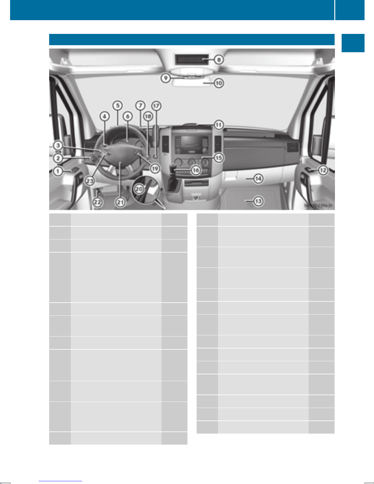
Cockpit
Cockpit
31
At a glance
Function Page
:
Door control panel 37
;
Light switch 79
=
Combination switch
• turn signals 81
• high-beam headlamps 81
• windshield wipers 93
• rear window wiper 94
?
Cruise control lever 140
A
Steering wheel without or
with buttons
B
Instrument cluster 32
C
Stowage compartment
• 3.5 mm audio jack 211
• USB port 211
D
Timer for the auxiliary warmair heater (auxiliary heating)
E
• Stowage compartment
with interior light
• Overhead control panel 36
35
114
84
Function Page
G
PARKTRONIC warning display
H
Opens/closes the right-hand
side window
I
Stowage compartment (jack
and vehicle tool kit)
J
Glove box 204
K
Center console 35
L
Selector lever (automatic
transmission)
M
Ignition lock 119
N
Further control panels 37
O
Steering wheel buttons 35
P
Engages/releases the parking brake
Q
Horn
R
Opens the hood 218
S
Steering wheel buttons 35
151
71
240
124
136
F
Rear-view mirror 78
Page 34
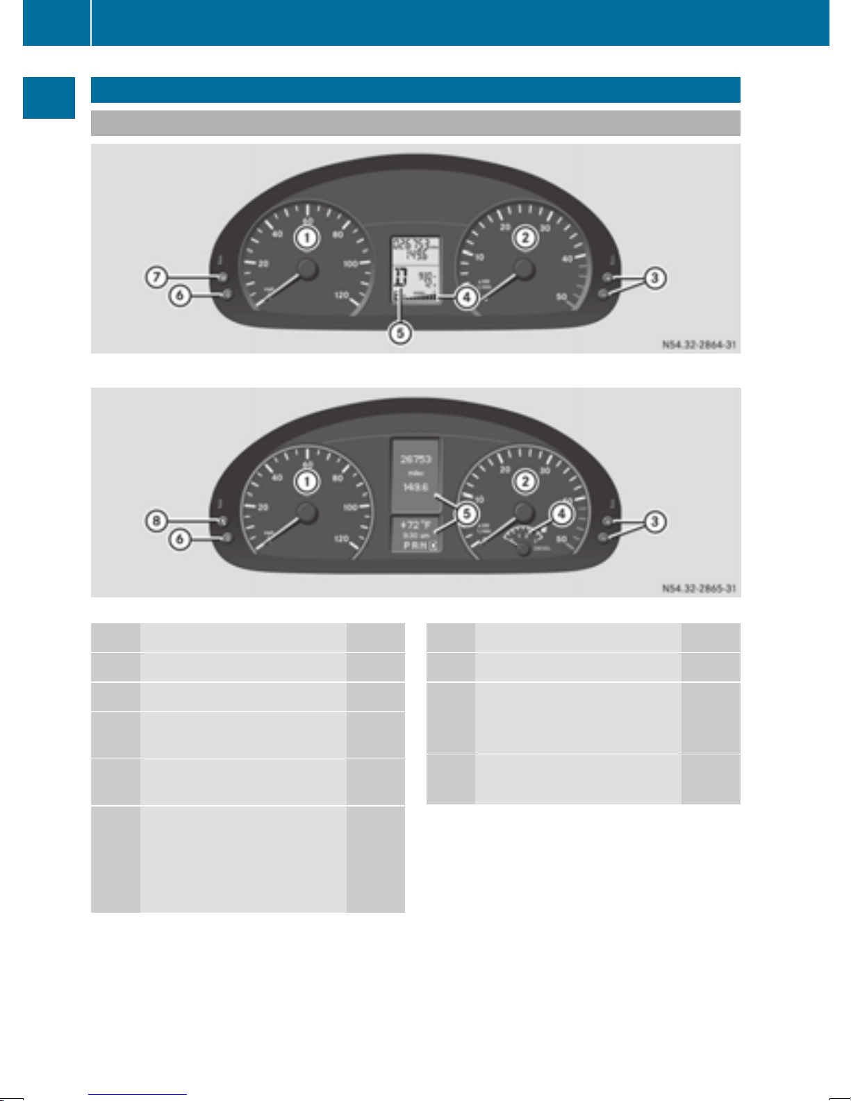
32
Instrument cluster
Instrument cluster
Displays and controls
At a glance
Instrument cluster on vehicles without steering wheel buttons
Instrument cluster in vehicles with steering-wheel buttons
Function Page
:
Speedometer 162
;
Tachometer 162
=
f, g Brightens/dims the
instrument cluster lighting
?
Fuel gage with fuel filler flap
location indicator
A
Display
Vehicles without steering
wheel buttons
Vehicles with steering wheel
buttons
162
162
163
164
B
C
D
Function Page
Reset button 9
Menu button 4
• changes standard display 163
• selects menus 164
Service button Ë
Checks the engine oil level 220
32
Page 35
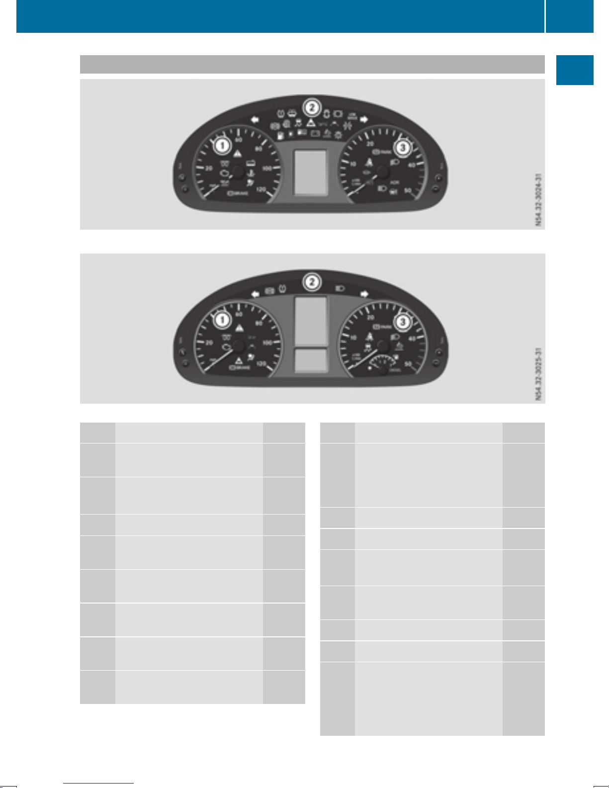
Indicator and warning lamps
Instrument cluster on vehicles without steering wheel buttons
Instrument cluster
33
At a glance
Instrument cluster in vehicles with steering-wheel buttons
Function Page
Speedometer with warn-
:
d
%
?
6
Ä
·
Ã
ing and indicator lamps
ESP®warning lamp 194
ASR warning lamp 194
Coolant level too low 199
Coolant temperature too
high
Restraint systems malfunction
Indicator lamp, distance
warning
Warning lamp, distance
warning
Warning and indicator lamps,
Lane Keeping Assist
199
39
143
143
147
b
4
;
%
;
G
!
h
Function Page
Brake fluid level too low 195
EBD malfunctioning 195
Trailer brake force booster
malfunction
Engine oil level warning 198
Check Engine indicator lamp 200
Preglow 120
Preglow system malfunction 201
Indicator and warning
lamps
Left-hand turn signal 81
ABS malfunction 195
Tire pressure loss or the tire
pressure monitor is malfunctioning (USA only)
Tire pressure loss (Canada
only)
195
202
255
Page 36

34
Instrument cluster
¦
å
At a glance
Ä
·
Ã
1
#
+
K
J
:
Function Page
Fluid level too low in windshield washer/headlamp
cleaning system
DEF supply low or contaminated/diluted
Exhaust gas aftertreatment
malfunction
Indicator lamp, distance
warning
Warning lamp, distance
warning
Warning and indicator lamps,
Lane Keeping Assist
Door or hood open 203
Electrically operated step
malfunction
Brake pads/linings worn 198
LOW RANGE active 148
High-beam headlamps on
(vehicle with steering wheel
buttons)
Right-hand turn signal 81
ASR malfunction 53
BAS malfunction 195
202
162
197
143
143
147
203
81
:
m
#
b
=
c
L
K
Ð
K
å
|
\
Function Page
Water in the fuel 202
Fuel filter dirty 202
Battery charging malfunction 198
Bulb defective 203
Tachometer with warning
and indicator lamps
Parking brake applied 136
Low-beam headlamps on 79
Working speed governor
(ADR) on
Power steering assistance
malfunction
High-beam headlamps on
(vehicle without steering
wheel buttons)
DEF supply low or contaminated/diluted
Exhaust gas aftertreatment
malfunction
Reserve fuel 200
Fuel filler cap open 200
Diesel particle filter malfunction
154
203
81
162
197
201
h
È
6
i
ESP®malfunction 194
Dirt accumulation in air filter 201
Reserve fuel 162
Fuel filler cap open 200
Corresponding messages may also be
shown in the display (
Y page 176).
h
7
ESP®malfunction 194
Fasten seat belts 203
Page 37

Center console
35
Steering wheel buttons
Function Page
:
Display 164
Center console
At a glance
On-board computer operation
;
Selects a submenu or adjusts
the volume
W Up/increases the volume
X Down/reduces the volume
Using the telephone 175
6 Accepts a call/starts
dialing
~ Ends a call/rejects an
incoming call
=
Scrolls from one menu to
another
V Forwards
U Back
Scrolls within a menu 164
9 Forwards
: Back
164
164
:
;
=
?
c
z
|
Function Page
Stowage compartment 205
Audio 10 or Audio 15 (see the
separate operating instructions)
Air-conditioning control
panel
Paper holder
Center console control
panel
Switches the left/right-hand
seat heating on/off
Switches the windshield
heating on/off
Switches the rear window
defroster on/off
1
97
207
76
104
104
1
Only on vehicles without rear-compartment climate control.
f
£
Activates/deactivates
PARKTRONIC
Switches the hazard warning
lamps on/off
153
82
Page 38
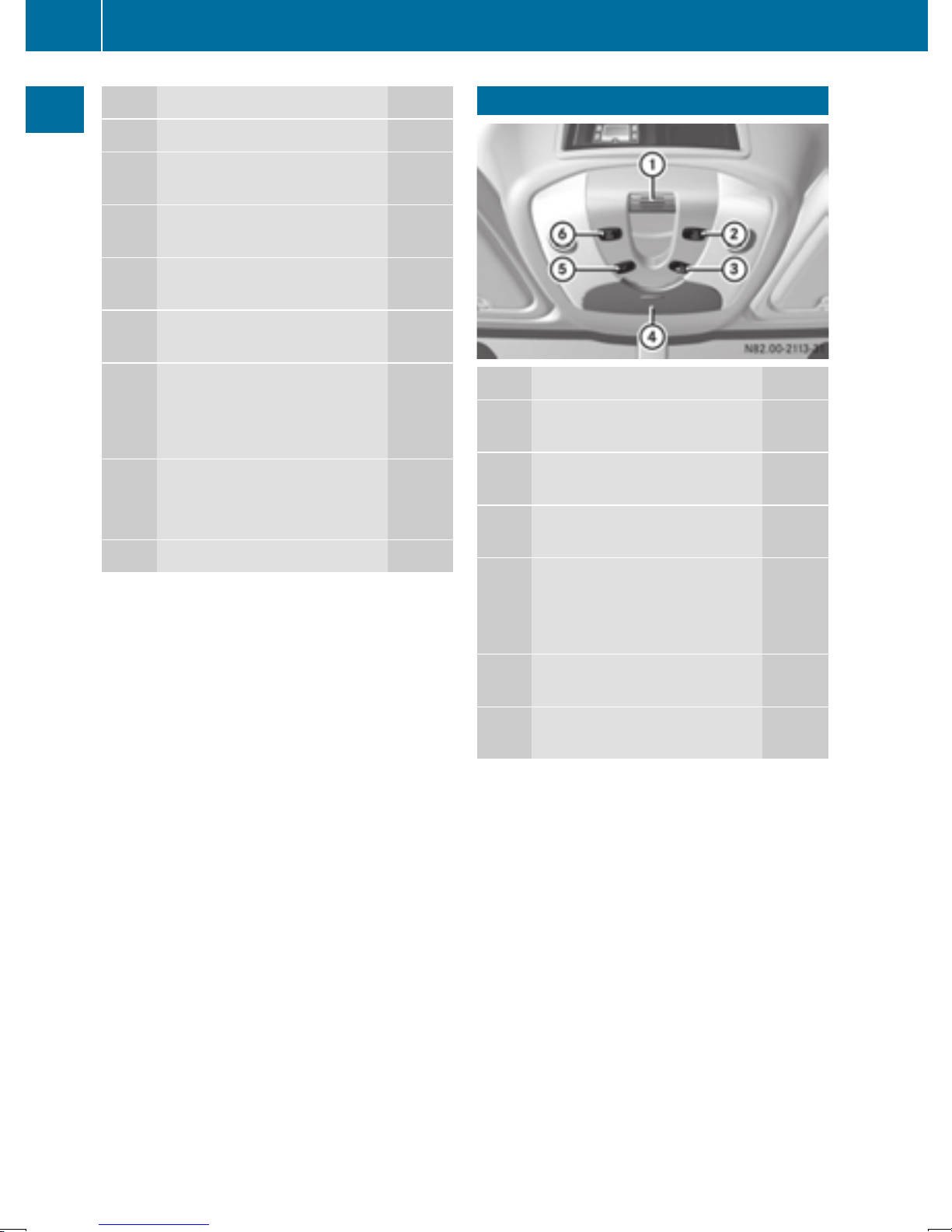
36
Overhead control panel
à
Ã
Ä
æ
At a glance
j
k
A
B
C
Function Page
Activates/deactivates ASR 53
Central locking, interior/rear
compartment
Activates/deactivates the
distance warning function
Activates/deactivates Lane
Keeping Assist
Activates/deactivates Blind
Spot Assist
• Stowage compartment or
• CD changer; see the separate operating instructions,
or
Cup holder with: 208
• Ashtray 209
• Cigarette lighter 209
12 V socket 210
64
143
147
144
Overhead control panel
Function Page
:
Microphone for the mobile
phone
;
Switches the right-hand
reading lamp on/off
=
Switches the automatic interior lighting on/off
?
• Eyeglasses compartment
or
• Anti-Theft Alarm system
(ATA)
210
84
84
205
56
A
Switches the interior lighting
on/off
B
Switches the left-hand reading lamp on/off
84
84
Page 39
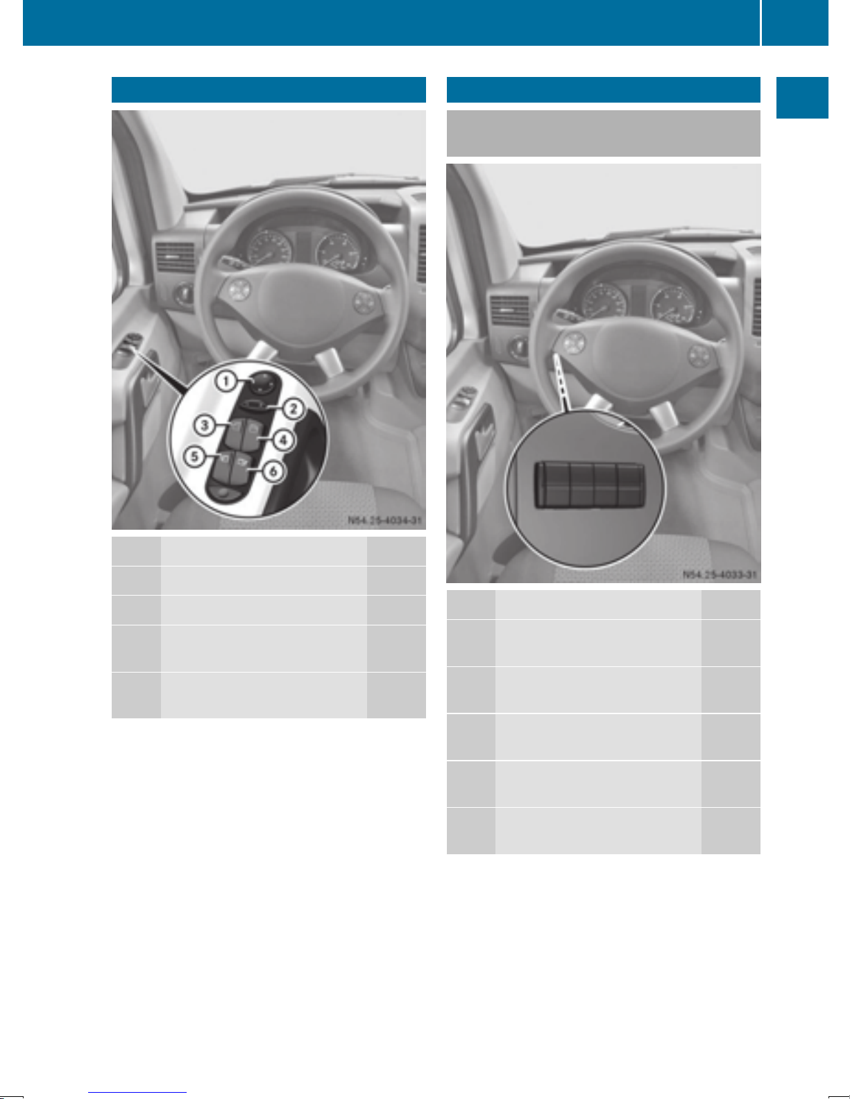
Further control panels
37
Door control panel
Further control panels
Control panel between the light
switch and the steering wheel
At a glance
Function Page
:
Adjusts the exterior mirrors 78
;
Selects an exterior mirror 78
=
Opens/closes the left-hand
side window
?
Opens/closes the right-hand
side window
71
71
y
±
E
F
E
´
·
Function Page
Switches the auxiliary heating on/off
Switches the heater booster
function on/off
Sets the working speed
Switches the working speed
governor (ADR) on/off
Ventilates the cargo compartment
108
111
154
154
117
Page 40
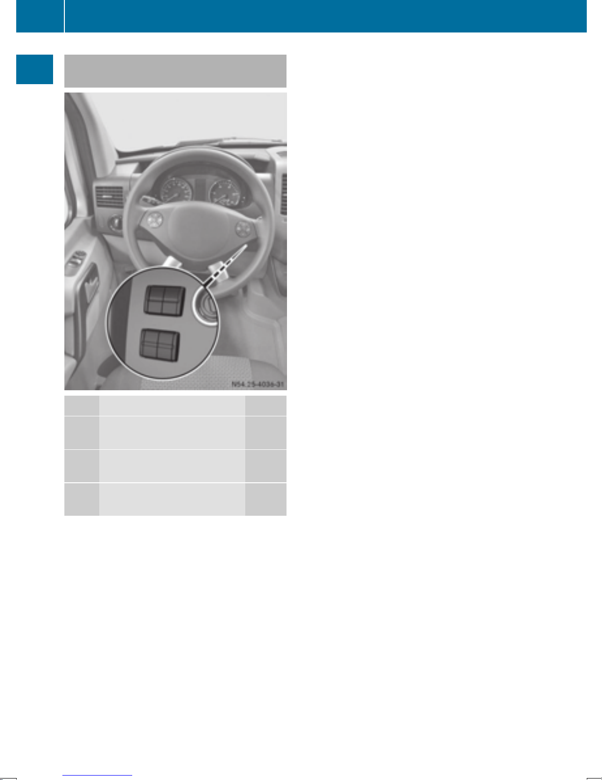
38
Further control panels
Control panel between the steering
wheel and the ignition lock
At a glance
l
k
;
m
Function Page
Switches the central rear
compartment lighting on/off
Engages/disengages allwheel drive
Activates/deactivates LOW
RANGE transmission ratio
84
148
148
Page 41

Occupant safety
39
Useful information
This Operator's Manual describes all models as
well as standard and optional equipment of your
vehicle that were available at the time of going
to print. Country-specific variations are possible. Note that your vehicle may not be equipped
with all of the described functions. This also
applies to systems and functions relevant to
safety.
Read the information on qualified specialist
workshops (
Y page 26).
Occupant safety
Restraint system introduction
The restraint system can reduce the risk of vehicle occupants coming into contact with parts of
the vehicle's interior in the event of an accident.
Furthermore, the restraint system may also
reduce the forces exerted on the vehicle occupants when an accident occurs.
The restraint system includes:
R
Seat belt system
R
Air bags
R
Child restraint system
R
Child seat securing systems
The components of the restraint system work in
conjunction with each other. They can only offer
the intended level of protection if all vehicle
occupants:
an accident are deployed. Seat belts and air
bags generally do not protect against objects
penetrating the vehicle from the outside.
Information on restraint system operation can
be found under "Triggering of Emergency Ten-
sioning Devices and air bags" (
Y page 45).
See “Children in the vehicle” for information on
children traveling with you as well as vehicle
restraint systems (
Y page 47).
Important safety notes
WARNING
G
Modifications to the restraint system, may
cause it to no longer work as intended. The
restraint system may then not perform its
intended protective function and may fail in an
accident or trigger unexpectedly, for example.
This poses an increased risk of injury or even
fatal injury.
Never modify parts of the restraint system.
Never tamper with the wiring, the electronic
components or their software.
If it is necessary to modify an airbag system to
accommodate a person with disabilities, contact an authorized Sprinter dealership for
details. USA only: contact our Customer
Assistance Center at 1‑877‑762‑8267 for
details.
Safety
R
are correctly wearing their seat belts.
Y page 41)
(
R
adjust their seat and head restraint properly
Y page 72).
(
The driver is also responsible for ensuring that
the steering wheel has been correctly positioned. Observe the information relating to the
correct driver's seat position (
Always ensure the air bag can inflate properly if
deployed (
Y page 43).
An air bag supplements a correctly fastened
seat belt. As an additional safety device, the air
bag increases the level of protection for vehicle
occupants in the event of an accident. For example, if the protection already provided by a correctly fastened seat belt will suffice, the air bags
are not deployed. Furthermore, only the air bags
that would increase the degree of protection
afforded to the vehicle occupants in the event of
Y page 72).
Restraint system warning lamp
The functions of the restraint system are
checked after the ignition is switched on and at
regular intervals while the engine is running.
Therefore, malfunctions can be detected in
good time.
The 6 restraint system warning lamp in the
instrument cluster lights up when the ignition is
switched on. It goes out no later than a few sec-
onds after the vehicle is started. The compo-
nents of the restraint system are in operational
readiness.
Z
Page 42

40
Occupant safety
A malfunction has occurred if the 6 restraint
system warning lamp:
R
does not light up after the ignition is switched
on
R
does not go out after a few seconds
R
goes out but then lights up again while the
engine is running, for example
WARNING
G
Safety
If restraint system is malfunctioning, restraint
system components may be triggered unintentionally or might not be triggered at all in
the event of an accident with a high rate of
vehicle deceleration. This can affect the Emergency Tensioning Device or air bag, for example. This poses an increased risk of injury or
even fatal injury.
Have the restraint system checked and
repaired in a qualified specialist workshop as
soon as possible.
Emergency Tensioning Devices tighten the seat
belts in an accident, pulling them close against
ver, pull
the occupant's body. They do not,
howe
vehicle occupants back towards the backrest.
Emergency Tensioning Devices do not correct
an incorrect seat position or incorrectly worn
seat belts.
When triggered, the seat belt force limiter
reduces the force exerted by the seat belt on the
vehicle occupant.
The seat belt force limiters are synchronized
with the front air bags, which absorb part of the
deceleration force. This makes it possible to
reduce the forces to which vehicle occupants
are subjected during an accident.
The Emergency Tensioning Device of the codriver's seat is triggered independently of the
lock status of the seat belt.
Important safety notes
The use of seat belts and child restraint systems
is required by law in:
Seat belts
Introduction
A correctly fastened seat belt is the most effective means of restraining the movement of vehicle occupants in the event of an accident or the
vehicle rolling over. This reduces the risk of
vehicle occupants coming into contact with
parts of the vehicle interior or being thrown from
the vehicle. Furthermore, the seat belt helps to
keep the vehicle occupants in the best position
in relation to the air bag.
The seat belt system consists of:
R
Seat belts
R
Emergency Tensioning Devices for the front
seat belts
If the vehicle is equipped with a front air bag,
the seat belt system also includes a seat belt
force limiter for the corresponding seat.
On vehicles with a front-passenger bench
seat, only the seat belt of the outer frontpassenger seat has a seat belt force limiter.
If the vehicle does not have a driver's air bag, the
seat belt system does not include an Emergency
Tensioning Device or a seat belt force limiter.
If the seat belt is pulled quickly or suddenly from
the belt outlet, the inertia reel locks. The belt
strap cannot be pulled out further.
R
all 50 states
R
the U.S. territories
R
the District of Columbia
R
all Canadian provinces
Even where this is not required by law, all vehicle
occupants should correctly fasten their seat
belts before starting the journey.
WARNING
G
If the seat belt is incorrectly fastened, it cannot protect as intended. Furthermore, an
incorrectly fastened seat belt can cause additional injury, for example, in an accident, during braking or when abruptly changing direction. This poses an increased risk of injury or
even fatal injury.
Make sure that all vehicle occupants are
seated properly with a correctly fastened seat
belt.
WARNING
G
The seat belt does not offer the intended level
of protection if you have not moved the backrest to an almost vertical position. When braking or in the event of an accident, you could
slide underneath the seat belt and sustain
abdomen or neck injuries, for example. This
Page 43

Occupant safety
41
poses an increased risk of injury or even fatal
injury.
Adjust the seat properly before beginning
your journey. Always ensure that the backrest
is in an almost vertical position and that the
shoulder section of your seat belt is routed
across the center of your shoulder.
WARNING
G
Persons under 5 ft (1.50 m) in height cannot
fasten the seat belt correctly without an additional suitable restraint system. If the seat
belt is incorrectly fastened, it cannot protect
as intended. Furthermore, an incorrectly fastened seat belt can cause additional injury, for
example, in an accident, during braking or an
abrupt change of direction. This poses an
increased risk of injury or even fatal injury.
For this reason, always secure persons under
5 ft (1.50 m) in height in suitable restraint
systems.
If a child younger than twelve years old and
under 5 ft (1.50 m) in height is traveling in the
vehicle:
R
always secure the child in a child restraint
system suitable for this vehicle. The child
restraint system must be appropriate to the
age, weight and size of the child
R
always observe the instructions and safety
notes in the "Children in the vehicle" section
of this Operator's Manual (
Y page 47) in
addition to the child restraint system manufacturer's installation instructions
WARNING
G
The seat belts may not perform their intended
protective function if:
R
they are damaged, modified, extremely
dirty, bleach or dyed
R
the seat belt buckle is damaged or
extremely dirty
R
the Emergency Tensioning Devices, belt
anchorages or inertia reels have been modified
Seat belts may sustain non-visible damage in
an accident, e.g. due to glass splinters. Modi-
fied or damaged seat belts may tear or fail,
e.g. in an accident. Modified Emergency Tensioning Devices could accidentally trigger or
fail to deploy when necessary. This poses an
increased risk of injury or even fatal injury.
Never modify the seat belts, Emergency Tensioning Devices, belt anchorages or inertia
reels. Make sure that the seat belts are
undamaged, not worn out and clean. Following an accident, have the seat belts checked
immediately at a qualified specialist workshop.
Only use seat belts that have been approved for
your vehicle by the sales organization named on
the inside cover.
Proper use of the seat belts
Pay attention to the safety notes about the seat
Y page 40).
belt (
All vehicle occupants must fasten the seat belt
correctly before setting off. Make sure that all
occupants are wearing their seat belts correctly
for the entire journey.
When fastening the seat belt, make sure that:
R
The seat belt tongue is inserted into the belt
buckle that belongs to the seat.
R
The seat belt is tightened across your body.
Avoid wearing bulky clothing, e.g. a winter
coat.
R
The seat belt is not twisted.
Only then can the forces produced in the
event of an accident be evenly distributed
across the belt.
R
The shoulder section of the belt must always
be routed across the center of the shoulder.
The shoulder section of the belt should not
come into contact with your neck and must
not be routed under the arm. Where possible,
adjust the seat belt to the appropriate height.
R
The lap belt must be taut and as low as possible over your lap.
The lap belt must always pass across your hip
joints and never across your stomach or
abdomen. Pregnant women must take particular care. If necessary, the lap belt can be
pushed down across the hip joints and pulled
tight using the shoulder section.
Safety
Z
Page 44
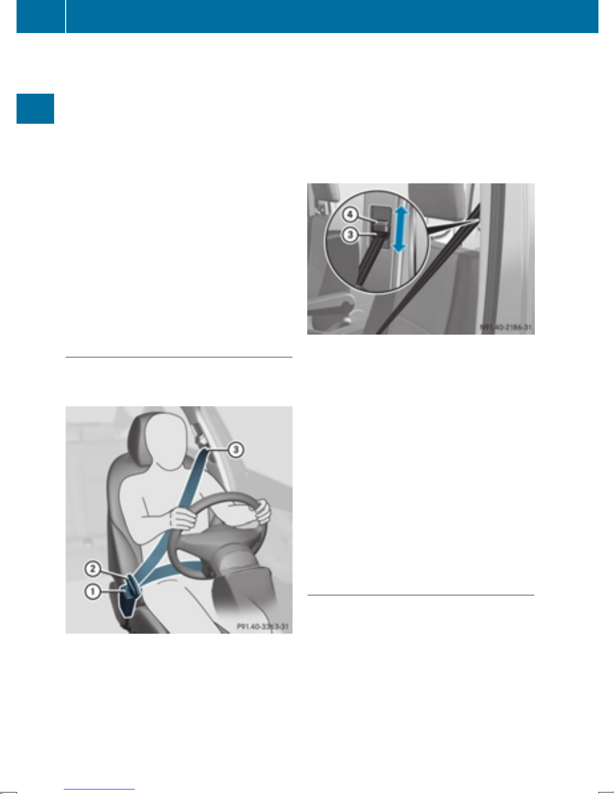
42
Occupant safety
R
The seat belt is not routed over sharp, pointed
or fragile objects.
If these items are on or in your clothing, e.g.
eyeglasses, pens, keys, etc., stow these items
in a more suitable location.
R
Only one person should use each seat belt at
any one time.
On no account should babies or children
travel sitting on the lap of another vehicle
Safety
occupant. During an accident, they could be
crushed between the occupant and seat belt.
R
Objects are not secured with a seat belt if the
seat belt is being used by one of the vehicle’s
occupants.
Also make sure that there are no objects, e.g.
cushions, between the occupant and the seat.
Seat belts are solely intended for the protection
and restraint of the vehicle occupants. To
secure objects, luggage or loads, always
observe the "Loading guidelines" (
Y page 212).
Fastening and adjusting seat belts
Observe the safety notes on the seat belt
Y page 40) and the notes on correct use of seat
(
Y page 41).
belts (
X
Adjust the seat (Y page 72).
The seat backrest must be in an almost vertical position.
X
Pull the seat belt smoothly from belt outlet =
and engage belt tongue ; into belt
buckle :.
X
If necessary, pull upwards on the shoulder
section of the seat belt to tighten the belt
across your body.
The shoulder section of the seat belt must
always be routed across the center of the shoulder. Adjust the belt outlet if necessary.
X
To raise: slide belt outlet = upwards.
The belt outlet will engage in various positions.
X
To lower: hold belt outlet release ? and slide
the belt outlet = downwards.
X
Let go of belt outlet release ? in the desired
position and make sure that the belt outlet
engages.
Basic illustration
All seat belts except the driver's seat belt are
equipped with a special seat belt retractor to
securely fasten child restraint systems in the
vehicle. Further information can be found under
"Special seat belt retractor" (
Y page 48).
Releasing seat belts
Make sure that the seat belt is fully rolled up.
!
Otherwise, the seat belt or belt tongue will be
trapped in the door or in the seat mechanism.
This could damage the door, the door trim
panel and the seat belt. Damaged seat belts
can no longer fulfill their protective function
and must be replaced. Visit a qualified specialist workshop.
Page 45
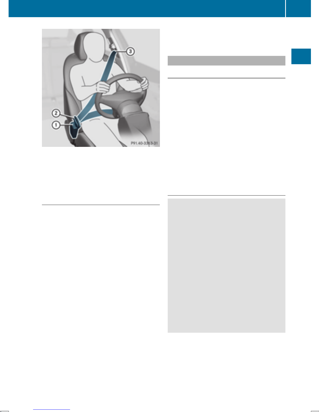
Basic illustration
X
Press release button :, hold belt tongue ;
firmly and guide it back towards belt outlet
=.
Occupant safety
lamps in the instrument cluster"
(
Y page 203).
Air bags
Introduction
The air bag installation location is identified by
the label SRS/AIR BAG or AIR BAG.
An air bag supplements a correctly fastened
seat belt. However, it is not intended as a sub-
stitute for the seat belt. Air bags provide addi-
tional protection in the event of an accident.
Not all air bags are deployed in an accident. The
various air bag systems work independently of
each other (
There is, however, no system available today
that can completely rule out injury or death.
It is also not possible to rule out a risk of injury
caused by an air bag due to the high speed at
which the air bag must be deployed.
Y page 45).
43
Safety
Belt warning for drivers and front passengers
The 7 seat belt warning lamp in the instrument cluster is a reminder that all vehicle occupants must wear their seat belts. It may light up
continuously or flash. In addition, there may be
a warning tone.
Regardless of whether the driver's seat belt has
already been fastened, the 7 seat belt warning lamp lights up for 6 seconds after each time
the ignition is switched on. After the engine has
been started, it goes out once the driver has
fastened the seat belt.
If the driver's seat belt is not fastened after the
engine is started, an additional warning tone will
sound. This warning tone stops after a maximum
of six seconds or once the driver's seat belt is
fastened.
If the vehicle speed exceeds 15 mph (25 km/h)
and the driver's seat belt is not fastened, a
warning tone sounds again. The warning tone
sounds for 60 seconds or until the driver's seat
belt is fastened.
If the driver unfastens the seat belt while the
vehicle is in motion, the belt warning automatically reactivates.
Further information on the 7 seat belt
i
warning lamp; see "Warning and indicator
Important safety notes
WARNING
G
If you do not sit in the correct seat position,
the air bag cannot protect as intended and
could even cause additional injury when
deployed. This poses an increased risk of
injury or even fatal injury.
To avoid hazardous situations, always make
sure that all of the vehicle's occupants:
R
have fastened their seat belts correctly,
including pregnant women
R
are sitting correctly and maintain the greatest possible distance to the air bags
R
follow the following instructions
Always make sure that there are no objects
between the air bag and the vehicle's occupants.
R
Correctly adjust the seats before driving off.
Always make sure the seat backrests are
positioned as close to the vertical as possible.
The center of the head restraints should support the back of the head at about eye level.
R
Move the driver's and front-passenger seat as
far back as possible. The driver's seat position
Z
Page 46
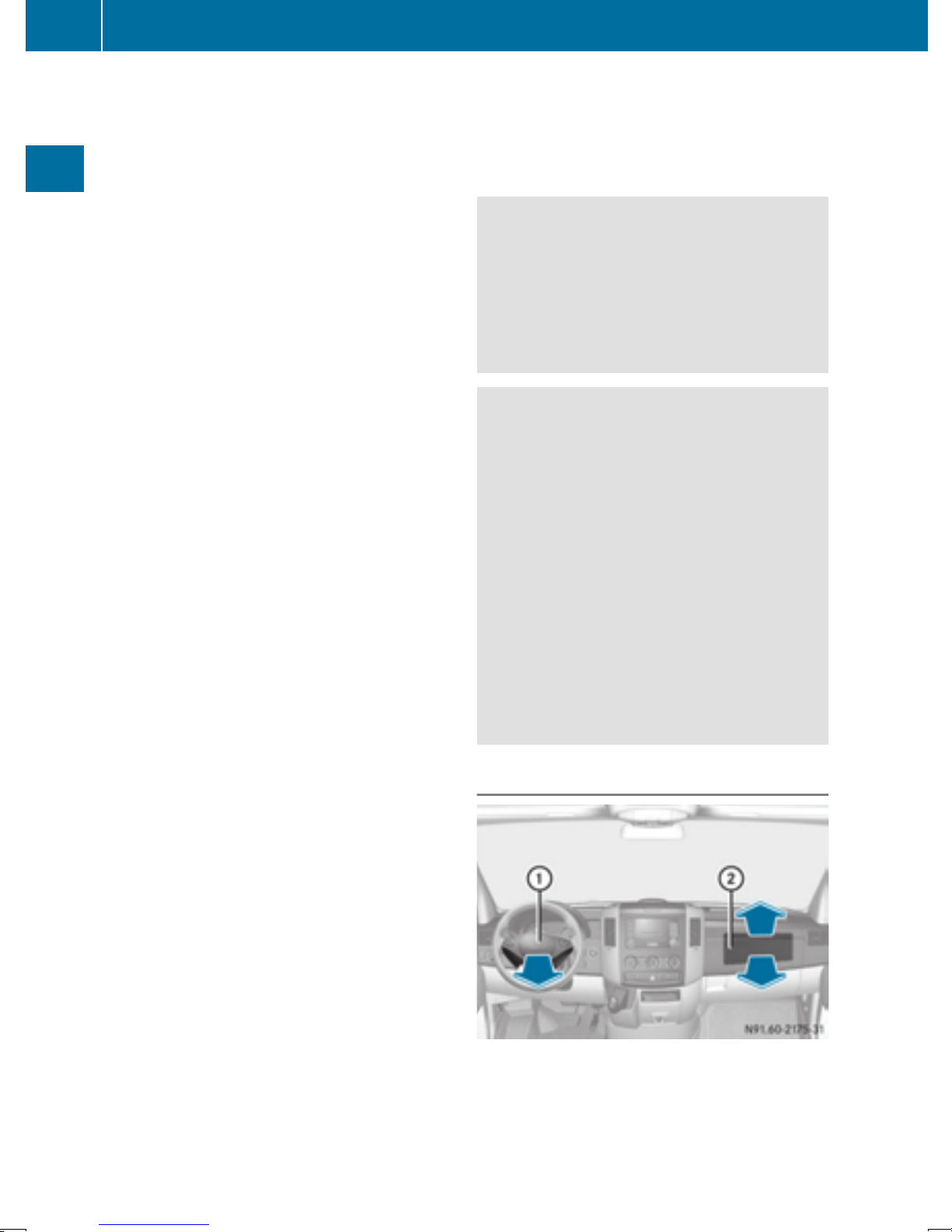
44
Occupant safety
must be such that the vehicle can be driven
safely.
R
Keep hands on the outside of the steering
wheel rim. This allows the air bag to deploy
fully.
R
Always sit with your back against the seat
backrest when driving. Do not lean forward,
on the door or against the side window. Otherwise, you are in the air bag deployment
Safety
area.
R
Always keep your feet in the footwell in front
of the seat. Do not, for example, place your
feet on the dashboard. Otherwise, your feet
are in the air bag deployment area.
R
Suitable restraint systems must always be
used for persons under 5 ft (1.50 m) in height.
The seat belt cannot be worn correctly by
persons who do not reach this height.
If children are also traveling in the vehicle,
please take note of the following points.
R
Always secure children younger than twelve
years of age and under 5 ft (1.50 m) tall in
suitable child restraint systems.
R
Child restraint systems should preferably be
installed on the rear seats.
R
If you secure a child in a rearward-facing child
restraint system, always do so on a suitable
rear seat. The front-passenger front air bag
cannot be deactivated.
R
Be sure to observe the instructions and safety
notes on "Children in the vehicle"
Y page 47) and "Child restraint system on
(
the front-passenger seat" (
Y page 51) in
addition to the child restraint system manufacturer's installation instructions.
Objects in the passenger compartment
could prevent an air bag from functioning
properly. To prevent risks due to the required
air bag speed after deployment, ensure the following before starting the journey:
area of an air bag, e.g. to doors or side windows.
R
there are no heavy, sharp or fragile objects in
the pockets of items of clothing. Such items
should be suitably stowed elsewhere.
WARNING
G
If you modify the air bag cover or affix objects
such as stickers to it, the air bag can no longer
function correctly. There is an increased risk
of injury.
Never modify an air bag cover or affix objects
to it.
WARNING
G
Sensors to control the air bags are located in
the doors. Modifications or work not performed correctly to the doors or door paneling, as well as damaged doors, can lead to the
function of the sensors being impaired. The air
bags might therefore not function properly
anymore. Consequently, the air bags cannot
protect vehicle occupants as they are
designed to do. There is an increased risk of
injury.
Never modify the doors or parts of the doors.
Always have work on the doors or door paneling carried out at a qualified specialist workshop.
Front air bags
R
there are no persons, animals or objects
between the vehicle occupants and an air
bag.
R
there are no objects between the seat, door
and B-pillar.
R
no hard objects, e.g. coat hangers, hang on
the grab handles or coat hooks.
R
no accessories, such as cup holders, are
attached to the vehicle within the deployment
Driver's air bag : deploys in front of the steering wheel. Front-passenger air bag ; deploys in
front of and above the glove box and the center
console.
Page 47
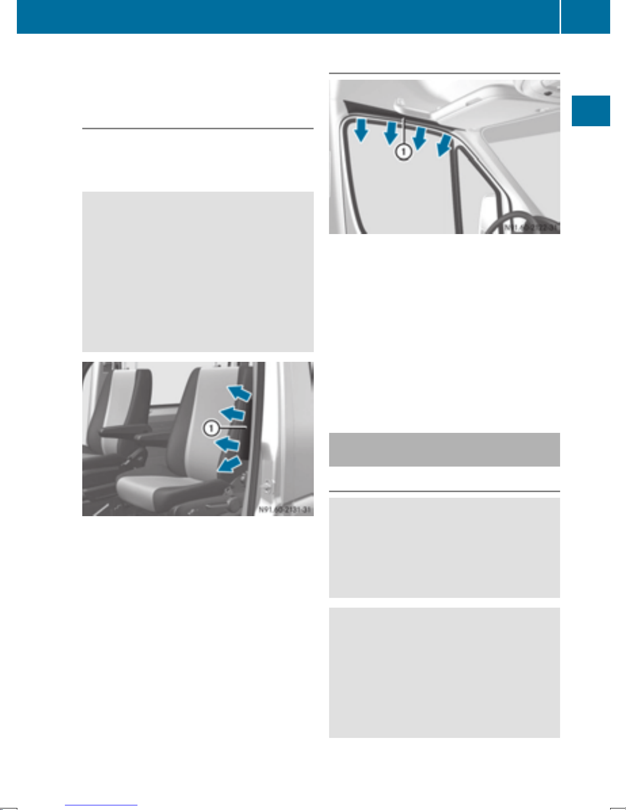
Occupant safety
45
When deployed, the front air bags offer additional head and thorax protection on the front
seats.
Side impact air bags
Depending on the vehicle's equipment, some
front seats are equipped with a side impact air
bag; see the AIR BAG label on the outer side of
the seat backrest.
WARNING
G
Unsuitable seat covers may obstruct or even
prevent deployment of the air bags integrated
into the seats. The air bags may then fail to
protect the vehicle occupants as intended.
There is an increased risk of injury, possibly
even fatal.
Only use seat cushions that are approved for
your vehicle by the distributor named on the
inside cover page.
Window curtain air bags
Window curtain air bags : are installed in the
side of the roof frame above the front doors.
When deployed, the window curtain air bag
offers additional head protection. However, it
does not protect the chest or arms.
In the event of a side impact, the window curtain
air bag is deployed on the side on which the
impact occurs.
If the system determines that it can offer addi-
tional protection to that provided by the seat
belt, a window curtain air bag may be deployed
in other accident situations (
Y page 45).
Safety
Side impact air bags : deploy next to the outer
bolster of the seat backrest.
When deployed, the side impact air bag offers
additional thorax protection. However, it does
not protect the:
R
head
R
neck
R
arms
In the event of a side impact, the side impact air
bag is deployed on the side on which the impact
occurs.
Deployment of Emergency Tensioning
Devices and air bags
Important safety notes
WARNING
G
The air bag parts are hot after an air bag has
been deployed. There is a risk of injury.
Do not touch the air bag parts. Have a
deployed air bag replaced at a qualified specialist workshop as soon as possible.
WARNING
G
A deployed air bag no longer offers any protection and cannot provide the intended protection in an accident. There is an increased
risk of injury.
Have the vehicle towed to a qualified specialist workshop in order to have a deployed air
bag replaced.
It is important for your safety and that of any
passengers to have deployed air bags replaced
Z
Page 48

46
Occupant safety
and to have any malfunctioning air bags
repaired. This will help to make sure the air bags
continue to perform their protective function for
the vehicle occupants in the event of a crash.
WARNING
G
Pyrotechnic Emergency Tensioning Devices
that have been deployed are no longer operational and are unable to perform their inten-
Safety
ded protective function. This poses an
increased risk of injury or even fatal injury.
Therefore, have pyrotechnic Emergency Tensioning Devices which have been triggered
immediately replaced at a qualified specialist
workshop.
If the Emergency Tensioning Devices or air bags
are deployed, you will hear a bang and a small
amount of powder may also be released. The
6 restraint system warning lamp will light up.
Only in rare cases will the bang affect your hearing. The powder released is generally not hazardous to health, it could however cause shortterm breathing difficulties in people with asthma
or other respiratory problems. If it is safe to do
so, you should leave the vehicle immediately or
open a window in order to prevent breathing
difficulties.
Air bags and pyrotechnic Emergency Tensioning
Devices (ETDs) contain perchlorate material,
which may require special handling and regard
for the environment. Check with your local government’s disposal guidelines. California residents, see www.dtsc.ca.gov/
HazardousWaste/Perchlorate/index.cfm.
Method of operation
During the first stage of a collision, the restraint
system control unit evaluates important physical data relating to vehicle deceleration or acceleration, such as:
R
Duration
R
Direction
R
Intensity
Based on the evaluation of this data, the
restraint system control unit triggers the Emergency Tensioning Devices in the event of a frontal or rear-end collision.
An Emergency Tensioning Device can only be
triggered if:
R
the ignition is switched on
R
the components of the restraint system are
operational. You can find further information
under "Restraint system warning lamp"
Y page 39)
(
R
the belt tongue is inserted into the buckle on
the respective front seat
The Emergency Tensioning Device of the codriver's seat is triggered independently of the
lock status of the seat belt.
If the restraint system control unit detects a high
accident severity, additional components of the
restraint system are deployed independently of
one another in certain frontal collision situations:
R
Front air bags
R
Window curtain air bag on side of collision
The deployment thresholds for the Emergency
Tensioning Devices and air bags are calculated
on the basis of the vehicle deceleration or acceleration occurring at various points in the
c
le. This process is pre-emptive in nature. The
vehi-
air bag must be deployed on time, at the start of
the collision.
The rate of vehicle deceleration or acceleration
and the direction of the force are essentially
determined by:
R
distribution of the force during the impact
R
collision angle
R
deformation characteristics of the vehicle
R
characteristics of the object with which the
vehicle has collided
Factors which can only be seen and measured
after the collision has occurred do not play a
decisive role in the deployment of an air bag, nor
do they provide an indication of air bag deployment.
The vehicle may be considerably deformed without an air bag being deployed. This is the case if
only relatively easily deformable parts have
been hit and a high rate of deceleration has not
been reached. Conversely, an air bag may be
deployed even though the vehicle suffers only
minor deformation. This is the case if, for example, very rigid vehicle parts such as the longitudinal body members are hit in an accident and
the rate of deceleration is sufficient.
Page 49

Children in the vehicle
47
If the restraint system control unit detects a side
impact situation, the applicable components of
the restraint system are deployed independently of each other. If the system determines a
need for additional protection for the vehicle
occupants, the Emergency Tensioning Devices
are also deployed.
R
Side impact air bag on the side on which the
impact occurs, independently of the Emergency Tensioning Device and of the use of the
seat belt
R
Window curtain air bag on the side of the collision, regardless of seat belt use and whether
front-passenger seat is occupied
Not all air bags are deployed in an accident.
i
The various air bag systems work independently of each other.
How the air bag system works is determined
by the severity of the accident detected,
especially the vehicle deceleration or acceleration, and the apparent type of accident:
R
frontal collision
R
side impact
WARNING
G
If you leave children unsupervised in the vehicle, they could set it in motion by, for example:
R
release the parking brake.
R
shift the automatic transmission out of the
parking position P.
R
start the engine.
In addition, they may operate vehicle equipment and become trapped. There is a risk of
an accident and injury.
When leaving the vehicle, always take the
SmartKey with you and lock the vehicle. Never
leave children unsupervised in the vehicle.
WARNING
G
If persons, particularly children are subjected
to prolonged exposure to extreme heat or
cold, there is a risk of injury, possibly even
fatal. Never leave children unattended in the
vehicle.
Safety
Children in the vehicle
Important safety notes
Accident statistics show that children secured
in the rear seats are safer than children secured
in the front-passenger seat. For this reason, we
strongly advise that you install a child restraint
system on a rear seat. Children are generally
better protected there.
If a child younger than twelve years old and
under 5 ft (1.50 m) in height is traveling in the
vehicle:
R
always secure the child in a child restraint
system suitable for this vehicle. The child
restraint system must be appropriate to the
age, weight and size of the child
R
be sure to observe the instructions and safety
notes in this section in addition to the child
restraint system manufacturer's installation
instructions
WARNING
G
If the child restraint system is subjected to
direct sunlight, parts may get very hot. Children may burn themselves on these parts,
particularly on the metal parts of the child
restraint system. There is a risk of injury.
If you leave the vehicle, taking the child with
you, always ensure that the child restraint
system is not exposed to direct sunlight. Protect it with a blanket, for example. If the child
restraint system has been exposed to direct
sunlight, let it cool down before securing the
child in it. Never leave children unattended in
the vehicle.
Always ensure that all vehicle occupants have
their seat belts fastened correctly and are sitting
properly. Particular attention must be paid to
children.
Observe the safety notes on the seat belt
(
Y page 40) and the notes on correct use of seat
Y page 41).
belts (
A booster seat may be necessary to achieve
proper seat belt positioning for children over
41 lbs (18 kg) until they reach a height where a
Z
Page 50

48
Children in the vehicle
three-point seat belt can be properly fastened
without a booster seat.
Special seat belt retractor
WARNING
G
If the seat belt is released while driving, the
child restraint system will no longer be
Safety
secured properly. The special seat belt retractor is disabled and the inertia real draws in a
portion of the seat belt. The seat belt cannot
be immediately refastened. There is an
increased risk of injury, possibly even fatal.
Stop the vehicle immediately, paying attention to road and traffic conditions. Reactivate
the special seat belt retractor and secure the
child restraint system properly.
All seat belts in the vehicle, except the driver's
seat belt, are equipped with a special seat belt
retractor. When activated, the special seat belt
retractor ensures that the seat belt cannot
slacken once the child seat is secured.
Installing a child restraint system:
X
Make sure you observe the child restraint
system manufacturer's installation instructions.
X
Pull the seat belt smoothly from the belt outlet.
X
Engage seat belt tongue in belt buckle.
Activating the special seat belt retractor:
X
Pull the seat belt out fully and let the inertia
reel retract it again.
While the seat belt is retracting, you should
tcheting sound. The special seat belt
ar a ra
he
retractor is enabled.
X
Push the child restraint system down so that
the seat belt is tight and does not loosen.
Removing the child restraint system and deactivating the special seat belt retractor:
X
Make sure you observe the child restraint
system manufacturer's installation instructions.
X
Press the release button of the seat belt
buckle and guide the seat belt tongue back
towards the belt sash guide.
The special seat belt retractor is deactivated.
Child restraint system
The use of seat belts and infant and child
restraint systems is required by law in:
R
all 50 states
R
the U.S. territories
R
the District of Columbia
R
all Canadian provinces
Further information about the correct child
restraint system is available from any authorized
Sprinter dealer.
WARNING
G
If the child restraint system is installed incorrectly on a suitable seat, it cannot protect as
intended. The child cannot then be restrained
in the event of an accident, heavy braking or
sudden changes of direction. There is an
increased risk of injury, possibly even fatal.
Make sure that you observe the child restraint
system manufacturer's installation instructions and the notes on use. Please ensure,
that the base of the child restraint system is
always resting completely on the seat cushion. Never place objects, e.g. cushions, under
or behind the child restraint system. Only use
child restraint systems with the original cover
designed for them. Only replace damaged
covers with genuine covers.
WARNING
G
If the child restraint system is installed incorrectly or is not secured, it can come loose in
the event of an accident, heavy braking or a
sudden change in direction. The child
restraint system could be thrown about, striking vehicle occupants. There is an increased
risk of injury, possibly even fatal.
Always install child restraint systems properly, even if they are not being used. Make
sure that you observe the child restraint system manufacturer's installation instructions.
You will find further information on stowing
objects, luggage and loads securely under
"Loading guidelines" (
Y page 212).
Page 51
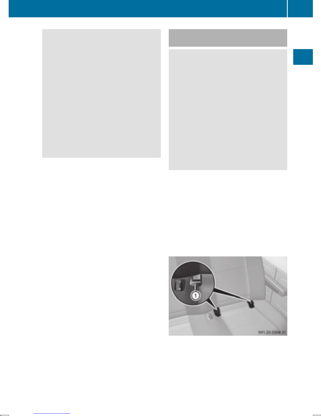
Children in the vehicle
49
WARNING
G
Child restraint systems or their securing systems which have been damaged or subjected
to a load in an accident can no longer protect
as intended. The child cannot then be
restrained in the event of an accident, heavy
braking or sudden changes of direction. There
is an increased risk of injury, possibly even
fatal.
Replace child restraint systems which have
been damaged or subjected to a load in an
accident as soon as possible. Have the securing systems on the child restraint system
checked at a qualified specialist workshop,
before you install a child restraint system
again.
Securing systems for child restraint systems
include:
R
the seat belt system
R
the LATCH-type (ISOFIX) securing rings
R
Top Tether anchorage points
If it is absolutely necessary to install a child
i
restraint system on the front-passenger seat,
be sure to observe the notes on "Child
restraint systems on the front-passenger
seat" (
Y page 51).
All child restraint systems must meet the following standards:
LATCH-type (ISOFIX) child seat securing system
WARNING
G
LATCH-type (ISOFIX) child restraint systems
do not offer sufficient protective effect for
children whose weight is greater than 48 lbs
(22 kg) who are secured using the safety belt
integrated in the child restraint system. In the
event of an accident, a child might not be
restrained correctly. This poses an increased
risk of injury or even fatal injury.
If the child weighs more than 48 lbs (22 kg),
only use LATCH-type (ISOFIX) child restraint
systems with which the child is also secured
with the vehicle seat belt. Also secure the
child restraint system with the Top Tether
belt, if available.
Always comply with the manufacturer's instal-
lation and operating instructions for the child
restraint system used.
Before every trip, make sure that the LATCH-
type (ISOFIX) child restraint system is engaged
correctly in both LATCH-type (ISOFIX) securing
rings
When installing the child restraint system,
!
make sure that the seat belt for the middle
seat does not get trapped. The seat belt could
otherwise be damaged.
Safety
R
U.S. Federal Motor Vehicle Safety Standards
213 and 225
R
Canadian Motor Vehicle Safety Standards
213 and 210.2
A statement by the child restraint manufacturer
of compliance with these standards can be
found on the instruction label on the child
restraint system. You will also find the statement in the instruction manual provided with the
child restraint system.
Observe the warning labels in the vehicle interior and on the child restraint system.
X
Install the LATCH-type (ISOFIX) child restraint
system on both LATCH-type (ISOFIX) securing
rings :.
Z
Page 52
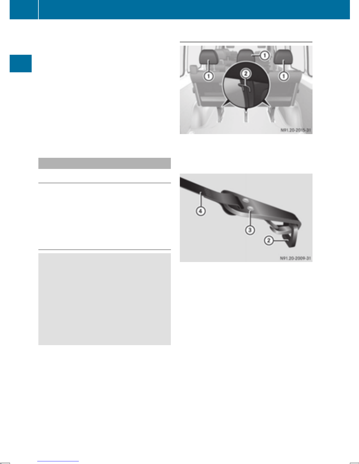
50
Children in the vehicle
ISOFIX is a standardized securing system for
specially designed child restraint systems on
the rear seats. LATCH-type (ISOFIX) securing
rings : for a LATCH-type (ISOFIX) child
restraint system are installed between the seat
cushion and the seat backrest:
R
on the outer left and right seat on rear bench
seats with 3 seats
R
on the outer left seat on rear bench seats with
Safety
2 seats
Non-LATCH-type (ISOFIX) child seats may also
be used and can be installed using the vehicle's
seat belt system. Install the child seat according
to the manufacturer's instructions.
Top Tether
Introduction
Top Tether provides an additional connection
between the LATCH-type (ISOFIX) child restraint
system and the vehicle. This helps reduce the
risk of injury even further. If the child restraint
system has a Top Tether belt, this should be
used at all times.
Top Tether anchorage points
Example: rear bench seat with 3 seats
Top Tether anchorages ; are on the bench seat
legs on the rear side of the respective rear bench
seat.
Important safety notes
WARNING
G
If the Top Tether belt has been incorrectly
secured, e.g. to an eyelet in the cargo compartment, the child restraint system is not
correctly kept in place. It therefore cannot
perform its intended protective function in the
event of an accident. There is an increased
risk of injury.
Only secure the Top Tether hook to the Top
Tether anchorage intended for this purpose.
X
Slide head restraint : upwards.
X
Install the LATCH-type (ISOFIX) child restraint
system with Top Tether. Make sure you
observe the child restraint system manufacturer's installation instructions.
X
Route the Top Tether belt ? under head
restraint : between the two head restraint
bars.
X
Hook Top Tether hook = into Top Tether
anchorage ;.
Make sure that:
R
the Top Tether hook = is hooked into Top
Tether anchorage ;, as shown
R
Top Tether belt ? is not twisted
X
Tighten Top Tether belt ?. Make sure you
observe the child restraint system manufacturer's installation instructions.
X
If necessary, push the head restraint back
down slightly (
Y page 76). Make sure that
you do not interfere with the correct routing of
Top Tether belt ?.
Page 53

Children in the vehicle
51
Child restraint system on the frontpassenger seat
General notes
Accident statistics show that children secured
in the rear seats are safer than children secured
in the front-passenger seat. For this reason,
Mercedes-Benz strongly advises that you install
the child restraint system on a rear seat.
Rearward-facing child restraint system
The front-passenger front air bag cannot be
deactivated. Always install a rearward-facing
child restraint system on a suitable rear seat.
Always observe the child restraint system manufacturer's installation and operating instructions.
Forward-facing child restraint system
If it is absolutely necessary to install a forwardfacing child restraint system on the frontpassenger seat, always move the frontpassenger seat as far back as possible. The
entire base of the child restraint system must
always rest on the seat cushion of the frontpassenger seat. The backrest of the child
restraint system must lie as flat as possible
against the backrest of the front-passenger
seat. The child restraint system must not be
subjected to a load by the head restraint. Adjust
the head restraint position accordingly. Always
make sure that the shoulder belt strap is correctly routed from the vehicle belt outlet to the
shoulder belt guide on the child restraint system. The shoulder belt strap must be routed forwards and downwards from the vehicle belt outlet. If necessary, adjust the vehicle belt outlet
and the front-passenger seat accordingly.
Always observe the child restraint system manufacturer's installation and operating instructions.
Override features/Child-proof locks
Important safety notes
WARNING
G
If children are traveling in the vehicle, they
could:
R
open doors, thus endangering other people
or road users
R
exit the vehicle and be caught by oncoming
traffic
R
operate vehicle equipment and become
trapped
There is a risk of an accident and injury.
Always activate the child-proof locks and
override feature if children are traveling in the
vehicle. When leaving the vehicle, always take
the key with you and lock the vehicle. Never
leave children unattended in the vehicle.
Child-proof locks for rear doors (
WARNING
G
If you leave children unsupervised in the vehicle, they could set it in motion by, for example:
R
release the parking brake.
R
shift the automatic transmission out of the
parking position P.
R
start the engine.
In addition, they may operate vehicle equipment and become trapped. There is a risk of
an accident and injury.
When leaving the vehicle, always take the
SmartKey with you and lock the vehicle. Never
leave children unsupervised in the vehicle.
WARNING
G
Y page 52).
Safety
If persons, particularly children are subjected
to prolonged exposure to extreme heat or
cold, there is a risk of injury, possibly even
fatal. Never leave children unattended in the
vehicle.
WARNING
G
If the child restraint system is subjected to
direct sunlight, parts may get very hot. Chil-
Z
Page 54
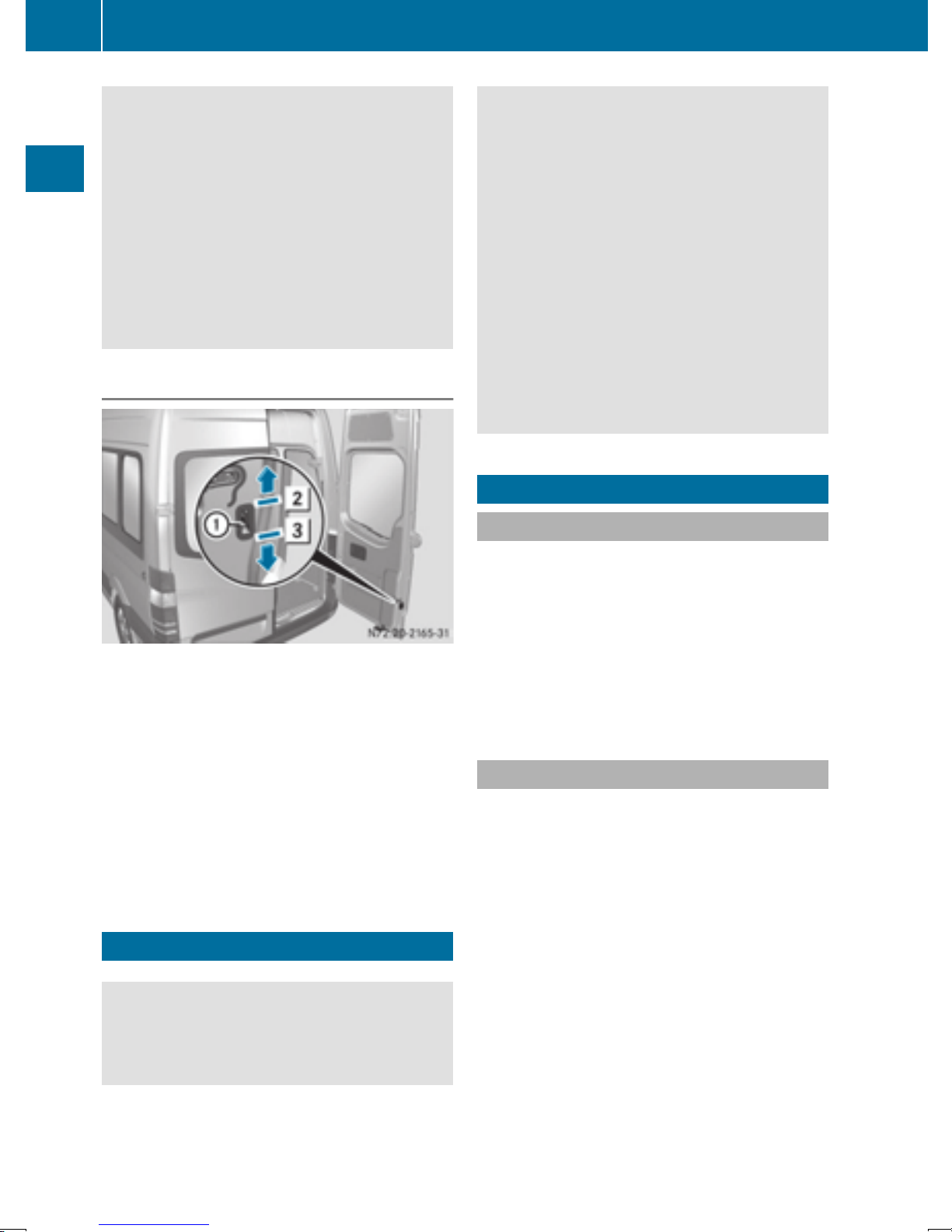
52
Driving safety systems
dren may burn themselves on these parts,
particularly on the metal parts of the child
restraint system. There is a risk of injury.
If you leave the vehicle, taking the child with
you, always ensure that the child restraint
system is not exposed to direct sunlight. Protect it with a blanket, for example. If the child
restraint system has been exposed to direct
Safety
sunlight, let it cool down before securing the
child in it. Never leave children unattended in
the vehicle.
Child-proof locks for the rear door
As a result, they could:
R
activate vehicle equipment and become
trapped, for example
R
activate or deactivate systems, thereby
endangering other road users
Unsecured animals could also be flung around
the vehicle in the event of an accident or sudden steering or braking, thereby injuring vehicle occupants. There is a risk of an accident
and injury.
Never leave animals unattended in the vehicle. Always secure animals properly during
the journey, e.g. use a suitable animal transport box.
Driving safety systems
Overview
Rear door
:
Child safety bolt
2
Door secured – then make sure that the
child-proof locks are working properly.
3
Door released
The child-proof lock on the doors enable you to
secure each door individually.
A door with an activated child-proof lock cannot
be opened from the inside. If the vehicle is
unlocked, the door can be opened from the outside.
Pets in the vehicle
WARNING
G
If you leave animals unattended or unsecured
in the vehicle, they could press buttons or
switches, for example.
In this section, you will find information about
the following driving safety systems:
R
ABS (Anti-lock Braking System)
R
ASR (Acceleration Skid Control)
R
BAS (Brake Assist System)
R
EBD (Electronic Brake Force Distribution)
R
ESP®(Electronic Stability Program)
Important safety notes
If you fail to adapt your driving style or if you are
inattentive, the driving safety systems can neither reduce the risk of accident nor override the
laws of physics. Driving safety systems are
merely aids designed to assist driving. You are
responsible for the distance to the vehicle in
front, for vehicle speed, braking in good time
and for staying in your lane. Always adapt your
driving style to the prevailing road and weather
conditions and maintain a sufficient, safe distance from other road users. Drive carefully.
Please note that the driving safety systems
described only work optimally when:
R
there is adequate contact between the tires
and the road surface
R
you use winter tires (M+S tires), with snow
chains if necessary, when the road conditions
are wintry.
Page 55

Driving safety systems
53
Pay particular attention to the information
regarding tires, tire tread and winter operation
under "Wheels and tires" (
Y page 247).
ABS (Anti-lock Braking System)
Important safety notes
Observe the important safety guidelines for the
driving safety system (
WARNING
G
If ABS is faulty, the wheels could lock when
braking. The steerability and braking characteristics may be severely impaired. Additionally, further driving safety systems are deactivated. There is an increased danger of skidding and accidents.
Drive on carefully. Have ABS checked immediately at a qualified specialist workshop.
If ABS is malfunctioning, other systems will also
fail, including driving safety systems. Observe
the information relating to the ! warning
lamp (
Y page 195).
ABS regulates brake pressure in such a way that
the wheels do not lock when you brake. This
allows you to continue steering the vehicle when
braking.
ABS works from a speed of about 5 mph
(8 km/h), regardless of road-surface conditions.
ABS works on slippery surfaces, even when you
only brake gently.
The yellow ! warning lamp in the instrument
cluster lights up when the ignition is switched
on. The lamp goes out when the engine starts
running.
Y page 52).
ASR (acceleration skid control)
General notes
Important safety notes
Observe the important safety guidelines for the
driving safety system (
Y page 52).
ASR can neither reduce the risk of an accident
nor suspend the laws of physics if the driver
does not pay attention when pulling away or
accelerating. ASR is only an aid. Always adapt
your driving style to suit the prevailing road and
weather conditions.
If you activate or deactivate the all-wheel drive
in a vehicle with this option, ASR will be deacti-
vated for the duration of the activation/deacti-
vation process.
Vehicles without steering wheel buttons: if ASR
is malfunctioning, the : indicator lamp lights
up while the engine is running and the engine
power may be reduced (
Y page 195).
ASR significantly improves traction, i.e. the
transmission of power from the tires to the road
surface, and thus increases the vehicle's driving
stability. If the driving wheels start to spin, ASR
brakes individual drive wheels and limits the
engine torque. ASR thus significantly assists you
when pulling away and accelerating, especially
on wet or slippery roads.
If traction on the road surface is not sufficient,
even ASR will not allow you to pull away without
difficulty. The type of tires and total weight of the
vehicle as well as the gradient of the road also
play a crucial role.
If ASR intervenes, the d warning lamp in the
instrument cluster flashes.
Activating/deactivating ASR
Safety
Braking
If ABS intervenes when braking, you will feel a
pulsating in the brake pedal.
The pulsating brake pedal can be an indication
of hazardous road conditions and functions as a
reminder to take extra care while driving.
X
If ABS intervenes: continue to depress the
brake pedal with force until the braking situation is over.
X
To make a full brake application: depress
the brake pedal with full force.
WARNING
G
If deactivated, ASR will not attempt to stabilize the vehicle during pulling away and acceleration. There is an increased risk of skidding
and of an accident.
Only deactivate ASR in the situations described in the following.
If you deactivate ASR, ESP®will still inter-
!
vene to stabilize the vehicle. Frequent braking
®
automatically triggered by ESP
can damage
the brake system.
Z
Page 56
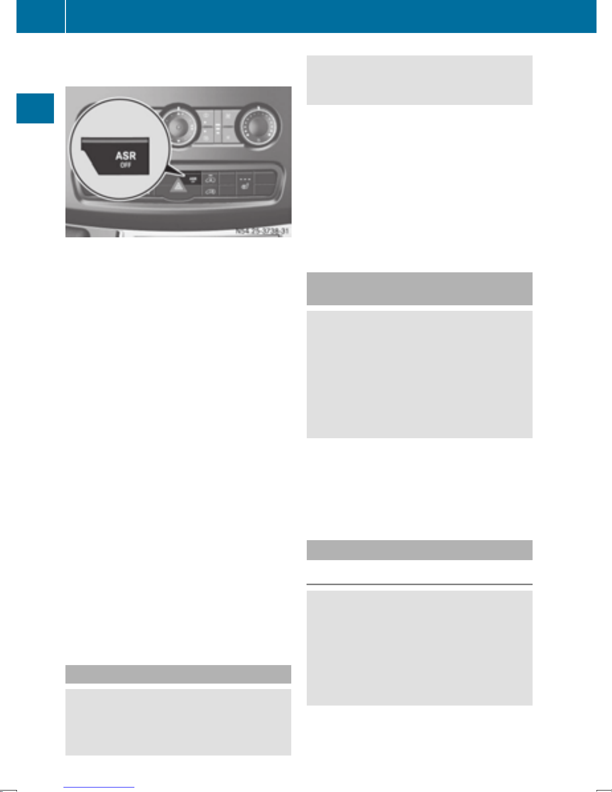
54
Driving safety systems
For this reason, deactivate ASR only briefly
and when absolutely necessary.
Safety
When ESP®is intervening and the d warning
lamp in the instrument cluster is flashing, leave
ASR on. In this case, only depress the accelerator pedal as far as required when pulling away.
X
Press the à button.
If ASR is deactivated, the d warning lamp
in the instrument cluster lights up.
ASR is automatically activated when the engine
is started.
It may be best to deactivate ASR briefly in the
following situations:
R
when using snow chains
R
in deep snow
R
on sand or gravel
If you deactivate ASR:
R
engine torque is not limited and the drive
wheels are able to spin. The spinning wheels
will then achieve a cutting effect for better
traction.
R
traction control remains active through brake
intervention. If a drive wheel attains its tire
traction limit because one side of the road is
slippery, for example, that wheel is braked.
The traction is then increased in this situation.
R
active brake intervention by ESP®to increase
driving stability remains active. The d
warning lamp in the instrument cluster
flashes when ESP
®
is intervening.
In an emergency braking situation, depress
the brake pedal with full force. ABS prevents
the wheels from locking.
Vehicles without steering wheel buttons: if the
BAS driving safety system is malfunctioning,
the : warning lamp lights up while the
engine is running (
Y page 195).
BAS operates in emergency braking situations.
If you depress the brake quickly, BAS automatically increases the brake pressure, thereby
reducing the stopping distance.
The brakes will function as usual once you
release the brake pedal. BAS is deactivated.
EBD (electronic brake force distribution)
WARNING
G
If EBD is malfunctioning, the rear wheels can
lock, e.g. under full braking. This increases the
risk of skidding and an accident.
You should therefore adapt your driving style
to the different handling characteristics. Have
the brake system checked at a qualified specialist workshop.
EBD monitors and controls the brake pressure
to the rear wheels. This enables EBD to improve
handling during braking.
Observe the information on warning and indicator lamps (
Y page 195).
ESP®(Electronic Stability Program)
Important safety notes
WARNING
G
®
If ESP
any vehicle stabilization. There is an increased
risk of skidding or of an accident.
is malfunctioning it will not provide
BAS (Brake Assist System)
WARNING
G
If BAS is malfunctioning, the braking distance
in an emergency braking situation is
increased. There is a risk of an accident.
Exercise caution when continuing to drive.
Have ESP
®
checked at a qualified specialist
workshop.
Do not run the vehicle on a roller dynamom-
!
eter (e.g. for performance tests). If you must
operate the vehicle on a roller dynamometer,
Page 57
Emergency exit
55
please consult a qualified specialist workshop
in advance. You could otherwise damage the
drive train or the brake system.
If you activate or deactivate the all-wheel drive
®
in a vehicle with this option, ESP
will be deactivated for the duration of the activation/deactivation process.
®
If ESP
is malfunctioning, the h indicator
lamp lights up while the engine is running and
the engine power may be reduced
Y page 194).
(
Only use wheels with the recommended tire
i
sizes. Only then will ESP
®
function properly.
4ETS (Electronic Traction System)
A function or performance test should only
!
be carried out on a two-axle dynamometer.
Before you operate the vehicle on such a
dynamometer, please consult a qualified
workshop. You could otherwise damage the
drive train or the brake system.
Crosswind Assist is operational again as soon as
the driving conditions return to normal.
Crosswind Assist detects strong crosswind
gusts that can impair the road holding of your
vehicle when driving straight ahead. Crosswind
Assist intervenes depending on the direction
and strength of the crosswind.
A stabilizing brake application helps you to keep
the vehicle on track.
Information appears in the instrument cluster In
the event that Crosswind Assist intervenes
noticeably.
On vehicles without steering wheel buttons:
the d indicator lamp in the instrument cluster flashes.
On vehicles with steering wheel buttons: the
d indicator lamp in the instrument cluster
flashes and the message Crosswind Assist
Active appears in the multifunction display.
Crosswind Assist is active above a vehicle speed
of 50 mph (80 km/h) when the vehicle is driving
straight ahead or cornering gently.
Safety
4ETS is only active when all-wheel drive is activated (
Y page 148).
4ETS ensures permanent drive for all four
®
wheels, and together with ESP
it improves the
vehicle's traction.
If a driven wheel spins due to lack of traction:
R
When pulling away, make use of the traction
control integrated in ESP
®
. Depress the
accelerator pedal as far as necessary.
R
While driving, slowly take your foot off the
accelerator pedal.
In wintry driving conditions, always use winter
tires (M+S tires) and if necessary, snow chains
Y page 249). This is the only way to get the full
(
benefit from the all-wheel drive system.
Crosswind Assist
Crosswind Assist does not work if ESP®is deactivated or disabled because of a malfunction.
Crosswind Assist does not react:
R
in the event of severe jolts and vibrations, e.g.
as a result of uneven surfaces or potholes
R
if the vehicle loses traction, e.g. on snow or
ice or when aquaplaning
R
to large and sudden steering movements by
the driver
Emergency exit
Emergency exit window
WARNING
G
The emergency exit window cannot be locked
in place. You risk injury if you exit the vehicle
through the emergency exit window.
R
Make sure that nobody becomes trapped,
both when closing and when opening the
emergency exit window.
R
The opened emergency exit window must
be held in place by another person.
Pay attention to traffic conditions.
WARNING
G
If the emergency exit window is unlocked
while driving, it could open and slam shut and
consequently fall down. There is a risk of an
accident and injury.
Before starting off, make sure that the emergency exit window is locked and the locking
pins are undamaged.
Make sure there is sufficient clearance
!
when opening the emergency exit window.
Z
Page 58
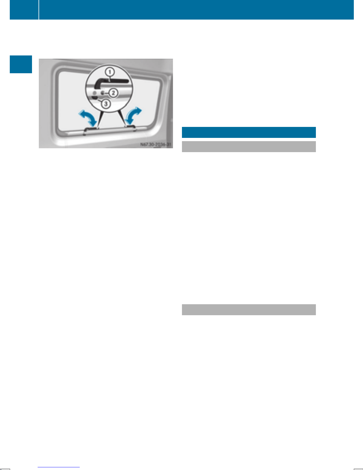
56
Theft deterrent locking system
Hold the open window in position. You could
otherwise damage the emergency exit window.
Safety
The emergency exit window is intended for use
in an emergency only and must not be opened
unless the vehicle is stationary. The emergency
exit window is the first window behind the driver's seat on the driver's side. It is marked by the
"Emergency Exit" label.
X
To open: position both handles : vertically.
This will break locking pins ;.
The window is unlocked.
X
Swing the window outward by the handles
and hold it in this position. Make sure there is
sufficient clearance when doing so.
X
To close: close the window.
X
Position both handles : horizontally. Make
sure that the locks = are inside in front of the
window frame.
The window is locked.
X
Replace locking pins ; at the latest before
starting on a new journey.
You can obtain information on this at any
qualified specialist workshop.
In an emergency, or after an accident, the vehicle occupants can exit the vehicle through the
emergency exit window.
Observe the following notes to make sure that
the emergency exit window can be used safely in
the event of an emergency:
R
Before beginning a journey, inform the vehicle
occupants of the emergency exit window and
explain how to use it. Make sure to explicitly
point out the risks described here.
R
Only vehicle occupants who know how to use
the emergency exit window are permitted to
sit next to it.
R
Access to the emergency exit window must
remain unobstructed. Do not place any large
or heavy objects on or in front of the seats
next to the emergency exit window
R
The window handles must not be used as
.
hooks, e.g. to hang up light objects, bags or
items of clothing.
R
When exiting the vehicle through the emergency exit window, pay attention to the vehicle height and the local conditions. Particularly children and smaller adults may require
assistance when exiting the vehicle.
Theft deterrent locking system
Immobilizer
X
To activate: remove the key from the ignition
lock.
X
To deactivate: turn the key to position 2 in
the ignition lock.
The immobilizer prevents your vehicle from
being started without the correct key.
Always take the key with you and lock the vehicle when leaving the vehicle. If you leave the key
in the vehicle, anyone can start the engine.
The immobilizer is always deactivated when
i
you start the engine.
In the event that the engine cannot be started
when the starter battery is fully charged, the
immobilizer may be faulty. Contact an authorized Sprinter dealer or call 1-877-762-8267
(in USA) or 1-800-387-0100 (in Canada).
ATA (Anti-Theft Alarm system)
X
To arm: close all doors.
X
Lock the vehicle with the key.
The indicator lamp in the central locking but-
Y page 64) flashes.
ton (
X
To disarm: unlock the vehicle with the key.
The indicator lamp in the central locking but-
Y page 64) goes out.
ton (
Cargo Van and Passenger Van only:
i
Unless you open a door within 40 seconds
after unlocking the vehicle:
R
the vehicle will be locked again
R
the anti-theft alarm system will be armed
again
Page 59
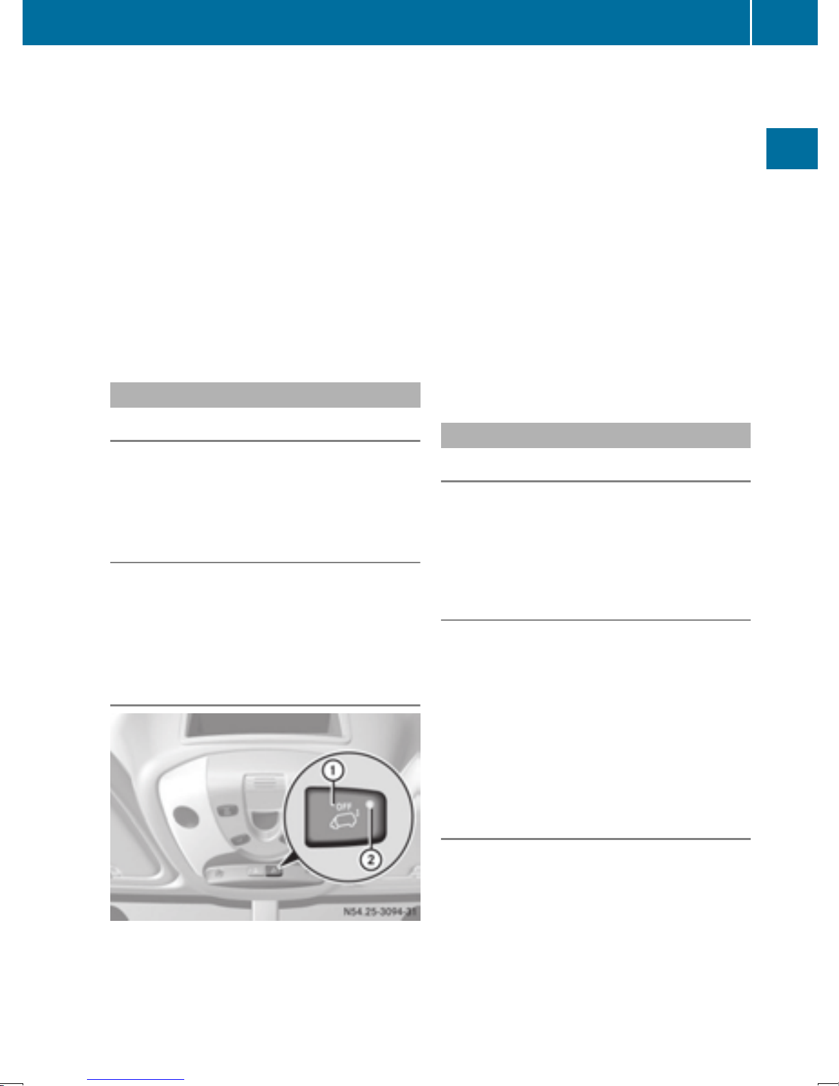
Theft deterrent locking system
57
If the alarm system is armed, a visual and audible alarm is triggered by the following:
R
Unlocking the vehicle from inside
R
Opening a door
R
Opening the hood
The alarm is not switched off, even if you
i
immediately close the open door that has triggered it, for example.
X
To stop the alarm: press the % button on
the remote control.
or
X
Insert the key into the ignition lock.
The alarm stops.
Tow-away alarm
Operation
A visual and audible alarm is triggered if the
inclination of the vehicle changes when the towaway alarm is armed. This can be the case if the
vehicle is raised on one side, for example.
Arming and disarming
The tow-away alarm is automatically armed
approximately 20 seconds after you lock the
vehicle.
The tow-away alarm is automatically deactivated when you unlock the vehicle.
Disarming
X
Remove the key from the ignition lock.
X
Press button :.
When the button is released, indicator
lamp ; in the button lights up for about
5 seconds.
X
Lock the vehicle.
The tow-away alarm is disarmed.
The tow-away alarm remains disarmed until you
lock the vehicle again.
Disarm the tow-away alarm when locking your
vehicle and:
R
loading and/or transporting the vehicle, on a
ferry or car transporter, for example
R
parking on a moving surface, as split-level
garage
This will prevent false alarms.
Interior motion sensor
Operation
If the armed interior motion sensor detects
motion in the vehicle interior, a visual and acoustic alarm is triggered. This can happen if someone reaches into the vehicle interior, for example.
Switching on
X
Close the side windows.
X
Make sure that nothing (such as mascots or
coat hangers) are hanging on the rear-view
mirror or on the grab handles on the headliner.
This will prevent false alarms.
X
Lock the vehicle.
The interior motion sensor is armed after
approximately 40 seconds.
Safety
Switching off
X
Unlock vehicle.
The interior motion sensor automatically
switches off.
Z
Page 60
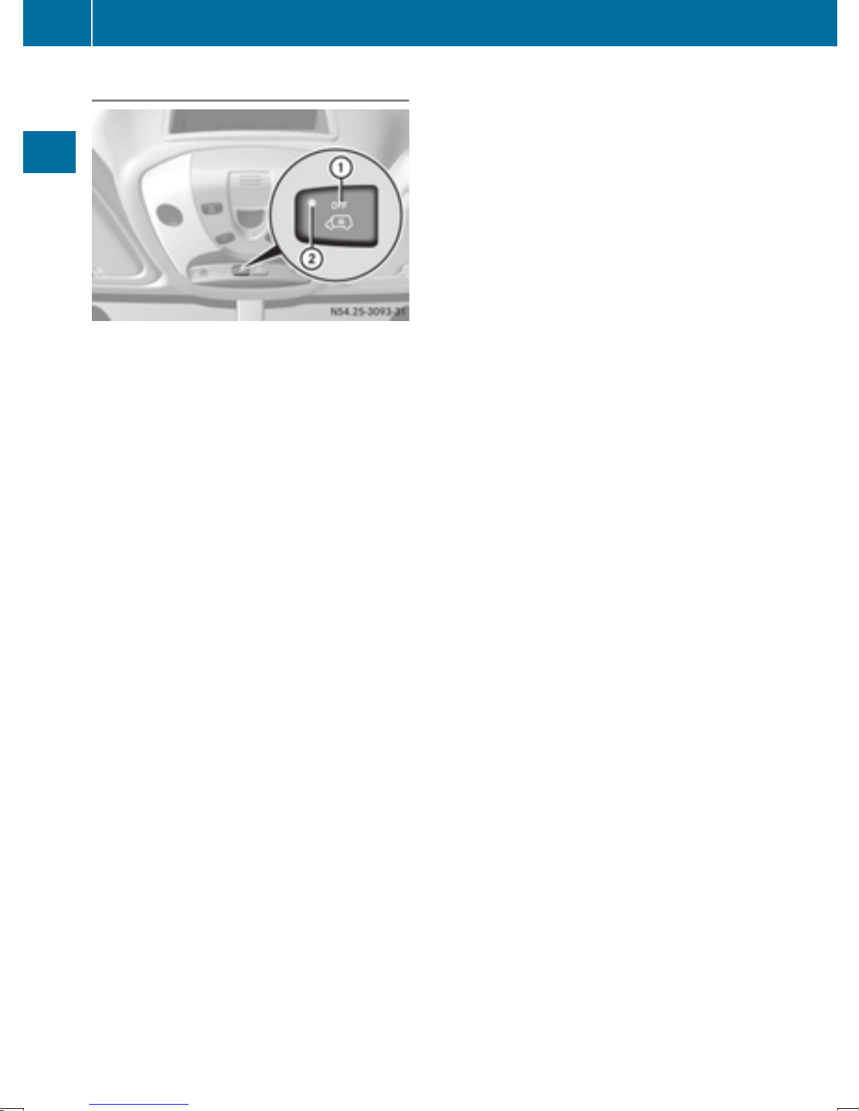
58
Theft deterrent locking system
Deactivating
Safety
X
Remove the key from the ignition lock.
X
Press button :.
When the button is released, indicator
lamp ; of the button lights up for about
5 seconds.
X
Lock the vehicle.
The interior motion sensor is deactivated.
The interior motion sensor remains deactivated
until you lock the vehicle again.
Deactivate the interior motion sensor when
locking your vehicle:
R
with people or animals remaining inside
R
with the side windows remaining open
R
when transporting it on a ferry or car transporter, for example
This will prevent false alarms.
Page 61

Key
59
Useful information
This Operator's Manual describes all models as
well as standard and optional equipment of your
vehicle that were available at the time of going
to print. Country-specific variations are possible. Note that your vehicle may not be equipped
with all of the described functions. This also
applies to systems and functions relevant to
safety.
Read the information on qualified specialist
workshops (
Y page 26).
Key
Important safety notes
WARNING
G
When the double locks are activated, the
doors can no longer be opened from the
inside. People in the vehicle can no longer get
out, e.g. in hazardous situations. There is a
risk of injury.
Therefore, do not leave any people unsupervised in the vehicle, particularly children, elderly people or people in need of special assistance. Do not activate the double lock when
people are in the vehicle.
WARNING
G
If you leave children unsupervised in the vehicle, they could set it in motion by, for example:
R
release the parking brake.
R
shift the automatic transmission out of park
position P or shift manual transmission into
neutral.
R
start the engine.
In addition, they may operate vehicle equipment and become trapped. There is a risk of
an accident and injury.
When leaving the vehicle, always take the
SmartKey with you and lock the vehicle. Never
leave children unsupervised in the vehicle.
WARNING
G
If you attach heavy or large objects to the
SmartKey, the SmartKey could be unintentionally turned in the ignition lock. This could
cause the engine to be switched off. There is a
risk of an accident.
Do not attach any heavy or large objects to the
SmartKey. Remove any bulky key rings before
inserting the SmartKey into the ignition lock.
Do not keep the key with remote control:
R
with electronic devices, e.g. a mobile phone
or another key with remote control
R
with metallic objects, e.g. coins or metal foil
R
in metallic objects, e.g. metal cases
This can affect the key's functionality.
Key functions of the remote control
General notes
The vehicle is equipped with either 2 or 4 remote
controls with a folding key, or 4 mechanical
keys. In this Operator's Manual, both the
mechanical keys and the keys with remote control are referred to as keys. The remote control
key has a range of up to 32 ft (10 m). Use the
remote control of the key only when in immediate proximity of the vehicle. This prevents theft.
Remote controls that are not included in the
scope of delivery for the vehicle must be programmed before use. Further information can
be obtained at any authorized Sprinter Dealer.
The key's remote control locks/unlocks the
driver's door and/or the following centrally if
the factory settings have not been changed:
R
the driver's and the front-passenger door
R
the sliding doors
R
the rear doors
If the driver's or front-passenger door is not
i
closed, the corresponding door is not locked.
If a sliding door or a rear door is not closed
properly, none of the rear doors are locked.
If there is a key is in the ignition lock, the remote
control is inoperative. When locking or unlocking the vehicle with the remote control, always
pay attention to the indicator lamp signaling.
Also check the locking knobs of the doors.
Opening and closing
Z
Page 62
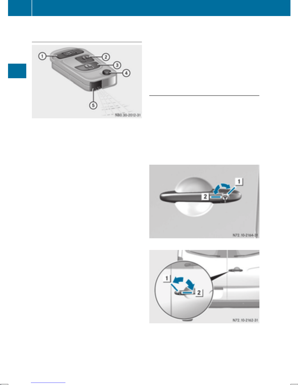
60
Key
Unlocking/locking the vehicle with the
remote control
Remote control with an integrated folding key
:
5 To unlock the sliding doors and the
rear door
;
% To unlock the driver's door only or
Opening and closing
unlock the vehicle centrally
=
& To lock the vehicle centrally
?
Key release button
A
Battery check lamp
X
To lock centrally: press the & button.
The indicator lamps flash three times when
the theft deterrent locking system has been
armed and all doors have been closed.
X
Check the locking knobs on all the doors.
The locking knobs must all be in the lowered
position.
Unlocking/locking the vehicle with the
mechanical key or the folding key
The anti-theft alarm system (ATA) is triggered if
you unlock and open the driver's door or the rear
door with the mechanical key or the folding key.
The alarm can be disabled in the following two
ways:
X
Press the % or & button on the remote
control.
Or
X
Insert the key into the ignition lock.
X
To unlock the driver's door: press the %
button.
The turn signals flash once. The theft deterrent locking system is deactivated.
To unlock the sliding doors and the rear
X
door: press the 5 button.
The turn signals flash once.
X
To unlock centrally: unlock the driver's
door.
X
Press the % button again within 2 seconds.
The turn signals flash once.
If the surround lighting has been switched
i
on using the on-board computer
Y page 172), it goes on when the vehicle is
(
unlocked.
If you do not open a Cargo Van or Passenger
Van within approximately 40 seconds of
unlocking:
R
the vehicle is locked again.
R
the theft deterrent locking system is armed
again.
Driver's door
Rear door
1
Locked
2
Unlocked
Page 63
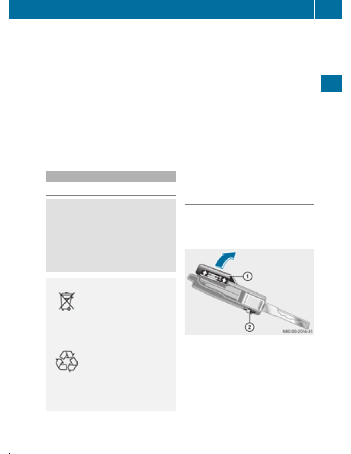
Key
61
X
To unlock the driver's or rear door: press
the key release button on the remote control.
The key folds out.
X
Insert the key fully into the door lock and turn
it to position 2.
The door is unlocked.
X
To lock the vehicle: lock all doors except the
driver's door and, if necessary the rear door,
from inside. To do this, press down the door
locking buttons.
X
Press the key release button on the remote
control.
The key folds out.
X
Insert the key fully into the driver's door lock
and turn it to position 1.
The driver's door is locked.
Remote control battery
Important safety notes
WARNING
G
Batteries contain toxic and corrosive substances. If batteries are swallowed, it can result in
severe health problems. There is a risk of fatal
injury.
Keep batteries out of the reach of children. If
a battery is swallowed, seek medical attention
immediately.
for the environment. Check with your local government’s disposal guidelines. California residents, see www.dtsc.ca.gov/
HazardousWaste/Perchlorate/index.cfm.
We recommend that you have batteries
changed at a qualified specialist workshop.
Checking the batteries
X
Press the % or & button for longer than
two seconds.
If battery indicator lamp (
Y page 59)lights up
briefly, the batteries in the remote control still
have sufficient charge. Otherwise, change the
batteries immediately.
i If the remote control is checked within the
signal reception range of the vehicle, pressing
the & or % button:
R
lock or
R
unlock the vehicle
Changing batteries
You need a CR 2025 2 3 V cell battery, which can
be obtained from any qualified specialist workshop.
When changing the batteries, do not press any
of the buttons on the remote control.
Opening and closing
Environmental note
H
Batteries contain dangerous
substances. It is against the
law to dispose of them with
the household rubbish. They
must be collected separately
and recycled to protect the
environment.
Dispose of batteries in an
environmentally friendly
manner. Take discharged
batteries to a qualified specialist workshop or a special
collection point for used batteries.
The key batteries contain perchlorate material,
which may require special handling and regard
X
Press release button ;.
The key folds out.
X
Remove battery compartment cover : in the
direction of the arrow.
Z
Page 64
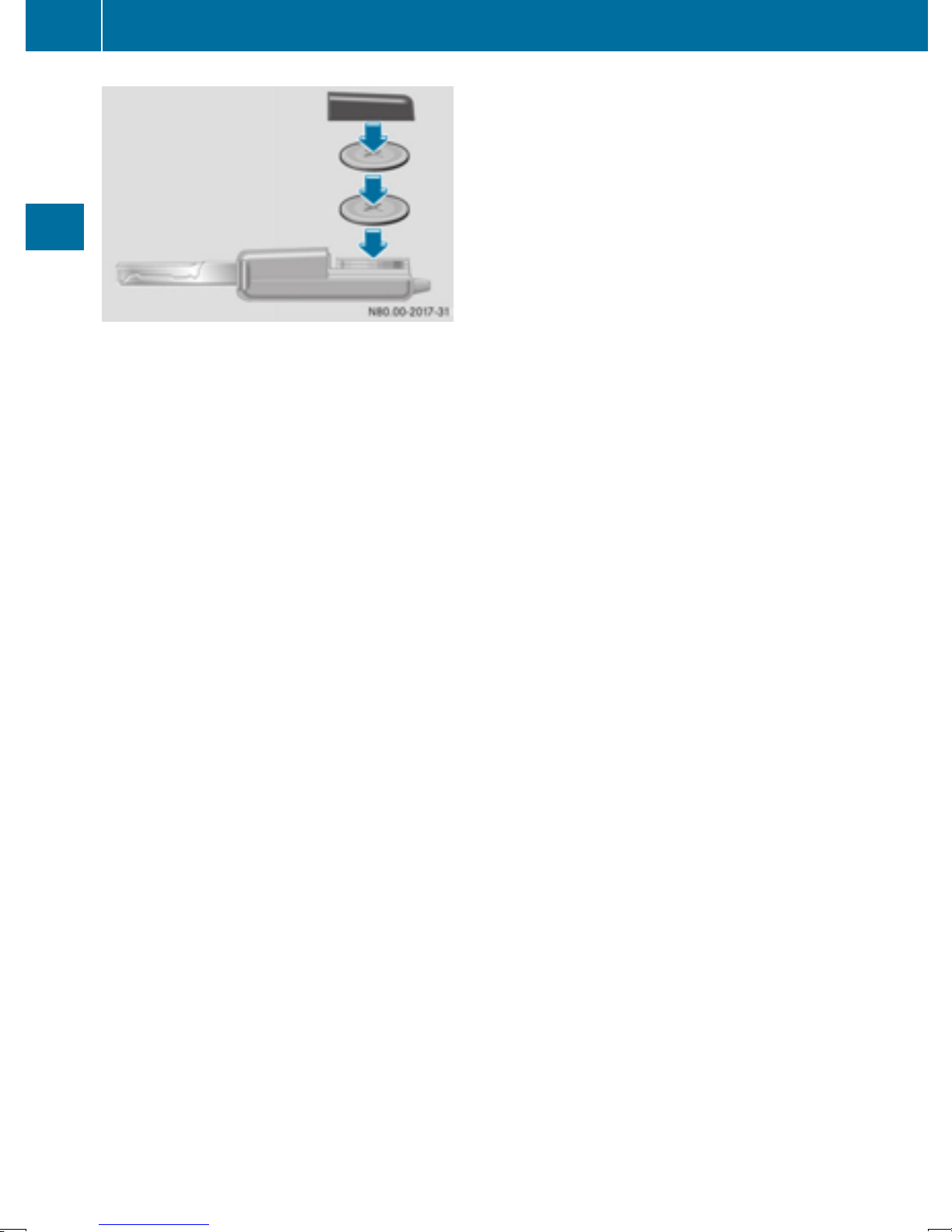
62
X
X
X
X
Opening and closing
Key
Remove the batteries from the battery tray.
Insert the new batteries into the battery tray
with the positive pole facing upwards. Use a
lint-free cloth to do so.
Align battery compartment cover : and push
it on until it audibly engages.
Check the function of all the remote control
buttons on the vehicle.
Page 65

Problems with the key/remote control
Key
63
Problem
It is no longer possible to
lock the vehicle using
the remote control.
The turn signals do not
flash when the vehicle is
locked.
It is no longer possible to
lock or unlock the vehicle using the remote
control.
Possible causes/consequences and M Solutions
The doors are not closed properly.
X
Close the doors properly and lock the vehicle again.
The central locking system has malfunctioned.
X
Lock the vehicle using the folding key (Y page 59).
X
Have the central locking system checked as soon as possible at a
qualified specialist workshop.
The key battery is weak or discharged.
X
Point the remote control at the driver's door handle from very close
range and press the % or & button.
If this does not work:
X
Replace the key battery (Y page 61).
or
X
Lock the vehicle using the folding key (Y page 59).
The remote control is faulty.
X
Lock the vehicle using the folding key (Y page 59).
X
Have the key checked at a qualified specialist workshop.
Opening and closing
The key cannot be
turned in the ignition
lock.
The engine cannot be
started using the key.
You have lost a key.
The steering lock has jammed mechanically.
X
Remove the key and insert it again into the ignition lock. Turn the
steering wheel from side to side while doing so.
The on-board voltage is too low.
X
Switch off all non-essential consumers, such as interior lighting, and
try to start the engine again.
If this does not work:
X
Check the starter battery and charge it if necessary (Y page 232).
or
X
Jump-start the vehicle (Y page 242).
or
X
Consult a qualified specialist workshop.
X
Have the key deactivated at a qualified specialist workshop.
X
Report the loss immediately to the vehicle insurers.
X
If necessary, have the mechanical locks replaced.
Z
Page 66
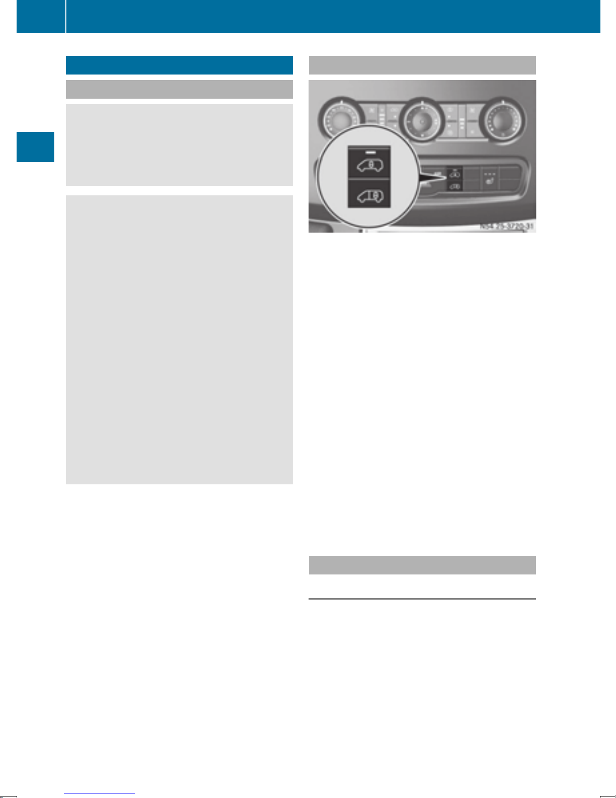
64
Central locking
Central locking
Important safety notes
WARNING
G
Activate the child-proof door locks if children
are traveling in the vehicle. The children could
otherwise open the doors while the vehicle is
in motion, injuring themselves and others.
WARNING
G
Do not leave children unsupervised in the
vehicle, even if they are secured in a child
restraint system. Children could otherwise
injure themselves on parts of the vehicle.
They could be severely or even fatally injured
by prolonged exposure to intense heat or
cold.
Opening and closing
If children open a door, they could:
R
injure other people
R
get out of the vehicle and thereby injure
themselves or be injured by a passing vehicle
R
severely injure themselves by falling down,
in particular due to the vehicle height
Always take the key with you when leaving the
vehicle, even if you are only leaving for a short
time.
You can open a locked front door from the inside
at any time. You can open a locked sliding door
or rear door from the inside if it has been previously unlocked from inside.
Locking and unlocking manually
Central locking buttons
Use the central locking buttons to centrally
lock/unlock either the entire vehicle or just the
sliding doors and rear doors from the inside.
X
To lock/unlock the entire vehicle: press
the upper à central locking button when
the doors are closed.
When the entire vehicle is locked, the indicator lamp in the à central locking button
lights up.
If the key has been removed or is in position
i
0 in the ignition lock, the indicator lamp in the
à central locking button remains lit for
5 seconds.
To lock/unlock the sliding doors and rear
X
doors: press the lower section of the Ä
central locking button when the doors are
closed.
When the sliding doors and rear doors are
locked, the indicator lamp in the upper Ã
central locking button lights up.
Automatic locking
General notes
The vehicle locks automatically as standard
once a speed of 9 mph (15 km/h) has been
reached. Depending on the vehicle's equipment, the doors may be locked automatically
once the ignition is switched on. Information on
the functions of the automatic locking mechanism of your vehicle can be obtained from any
authorized Sprinter Dealer.
If the automatic locking when driving function is
activated, there is a risk of being locked out
when the vehicle is pushed or towed.
Page 67
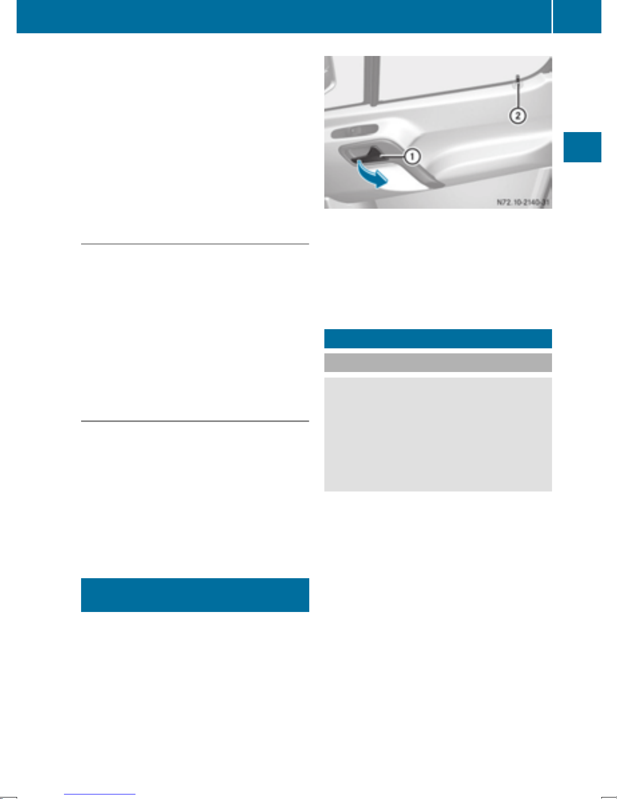
For this reason, deactivate the automatic locking when driving function:
R
before pushing the vehicle
R
before towing the vehicle
If activated, automatic locking is deactivated
when the vehicle is unlocked or locked using the
central locking button.
Automatic locking is reactivated after the ignition is switched off or a door is opened with the
vehicle stationary.
Sliding door
65
Activating automatic locking when driving
X
Turn the key to position 1 or 2 in the ignition
lock when the doors are closed.
X
For the entire vehicle: press the upper Ã
central locking button until the indicator lamp
in the button flashes four times.
For the sliding doors and rear doors only:
X
press the Ä lower central locking button
until the indicator lamp in the à upper
button flashes four times.
Deactivating automatic locking when
driving
X
Turn the key to position 1 or 2 in the ignition
lock when the doors are closed.
X
For the entire vehicle: press the à upper
central locking button until the indicator lamp
in the button flashes twice.
For the sliding doors and rear doors only:
X
press the Ä lower central locking button
until the indicator lamp in the à upper
button flashes twice.
You can open the driver's or front-passenger
door from the inside at any time, even if it is
locked.
X
Pull door handle :.
Locking knob ; pops up.
The door opens.
Sliding door
Important safety notes
WARNING
G
If the open sliding door is not engaged, it could
move on its own if the vehicle is on a slope.
This could trap you or other persons. There is
a risk of injury.
Always make sure that the open sliding door is
engaged.
Only open the doors when road and traffic
!
conditions permit. Make sure that there is
sufficient clearance when opening the doors.
Otherwise, you could damage your vehicle or
other vehicles.
Opening and closing
Driver's door and front-passenger
door
Only open the doors when road and traffic
!
conditions permit. Make sure that there is
sufficient clearance when opening the doors.
Otherwise, you could damage your vehicle or
other vehicles.
The sliding door of your vehicle can be equipped
with an electrical access step. Observe the
notes on the electrical step when opening and
closing the sliding door (
Y page 66).
Z
Page 68
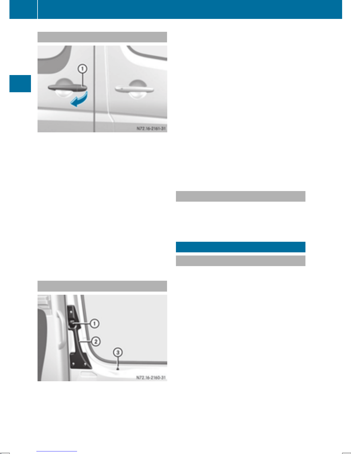
66
Electrical step
Opening/closing from the outside
The sliding door is equipped with an active
retainer, which engages the door at the end stop
when opened.
You can also lock the sliding door in place
i
around halfway when opening and closing.
The door does not have to be opened fully
Opening and closing
when getting into or out of the vehicle. The
intermediate detent does not fully engage the
sliding door.
X
To open: pull door handle :.
The sliding door opens.
X
Push back the sliding door using door handle : until it engages.
X
Check the sliding door detent.
X
To close: slide the sliding door firmly forwards by handle : until it closes.
The door does not have to be opened fully
when getting into or out of the vehicle. The
intermediate detent does not fully engage the
sliding door.
X
To unlock: pull locking knob = upwards.
Only this sliding door unlocks. The other
doors remain locked.
X
To open: press button :.
X
Slide the sliding door by handle ; back to the
stop.
X
Check the sliding door detent.
The sliding door must be engaged.
X
To close: slide the sliding door firmly forwards by door handle ; until it engages.
X
To lock: press locking knob = down.
Only the sliding door is locked. All other doors
that were previously unlocked remain
unlocked.
Electrical closing assist
If your vehicle is equipped with electrical closing
assist, you will require less force to close the
sliding door.
Electrical step
Important safety notes
Opening/closing from the inside
Interior door handle on the sliding door
The sliding door is equipped with an active
retainer, which engages the door at the end stop
when opened.
You can also lock the sliding door in place
i
around halfway when opening and closing.
Always observe the ground clearance of the
!
vehicle and avoid obstacles. On vehicles with
a step, ground clearance is further restricted.
Obstacles can damage the vehicle.
If you must drive over obstacles, drive especially slowly and carefully. If necessary, have
another person direct you.
If you do not use the grab handle and the step,
you could injure yourself when getting in and out
of the vehicle.
In order to reduce risks:
R
draw the passengers' attention to the electrical step. Wait until the electrical step is fully
extended.
R
do not jump out of the vehicle.
R
only use the grab handle and step. Only they
are designed for such a load.
R
keep grab handles, access steps and entry
sills free from dirt, e.g. mud, clay, snow and
ice.
Page 69
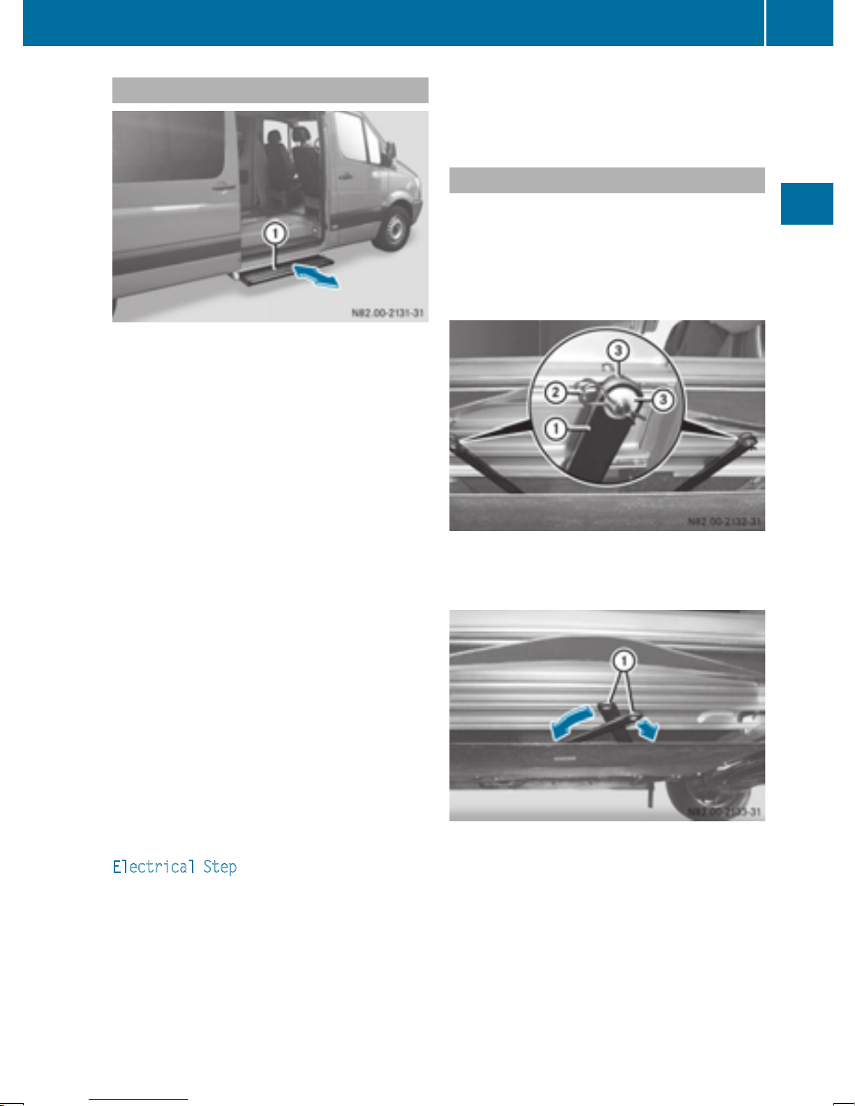
Electrical step
67
Operation and obstacle detection
Electrical step
The sliding door of your vehicle can be equipped
with an electrical step.
X
When getting in and out of the vehicle, use the
grab handles and electrical step :.
Electrical step : automatically extends when
the sliding door is opened and retracts when it is
closed.
Electrical step : is equipped with an obstruction detection device on the front side. If the
step comes into contact with an obstacle while
it is extending, it stops.
After you have removed the obstacle, you must
first close the sliding door and open it once
again so that the step can extend completely.
Before passengers get out of the vehicle, let
them know that electrical step : might not be
extended.
Emergency release
Driving with the step extended may result in
!
it being damaged.
If the electrical step does not retract auto-
matically, you will have to push it in and lock it
into place manually before continuing your
journey.
X
Pull R-clips ; on both rods : on the underside of the step out of their respective pins.
X
Remove washers = and detach both rods :.
Opening and closing
If the electrical step obstructs loading, you
i
can prevent the step from extending when
opening the sliding door via obstacle detection. The electrical step can then remain
retracted and a forklift or other lifting equipment can be moved nearer to the cargo compartment.
Vehicles without steering-wheel buttons: if
the 1 indicator lamp in the instrument cluster lights up and a warning tone sounds, electrical step : is malfunctioning (
Y page 203).
Vehicles with steering wheel buttons: if the
Electrical
Step message is shown in the dis-
play and a warning tone sounds, electrical
step : is malfunctioning (
Y page 192).
If electrical step : is malfunctioning, the step
may only partially extend/retract or may not
extend/retract at all. If a malfunction does
occur, you will have to retract and lock electrical
step : manually before continuing the journey
Y page 67).
(
X
Fold rods : into the housing in the step.
X
Push the step into its housing.
Z
Page 70
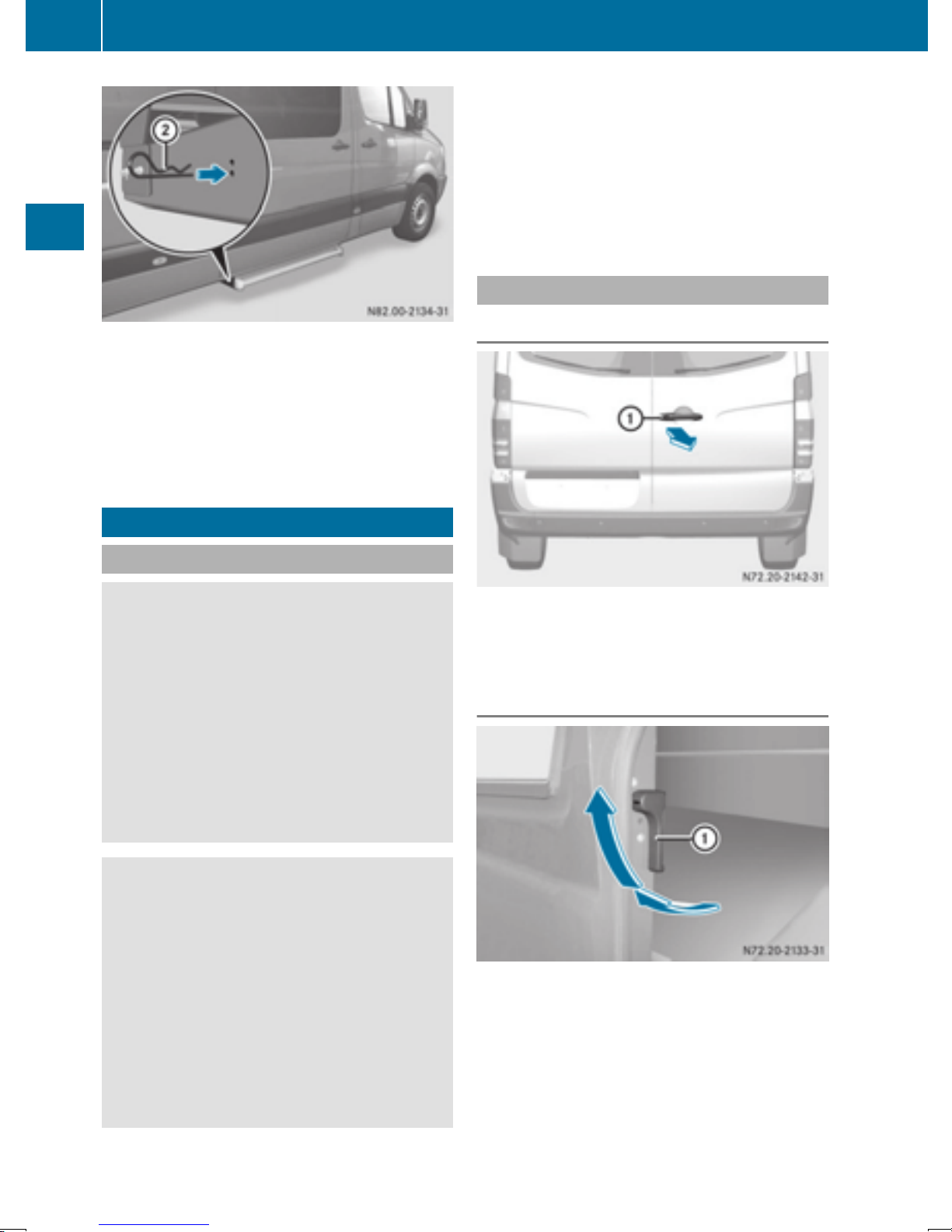
68
Rear doors
When securing the step for the first time,
i
you must pierce a film with the R-clips.
X
Insert R-clips ; into the step as far as they
will go through the holes on both sides of the
housing.
The step is secured in its housing.
Make sure that there is sufficient clearance
!
when opening the rear doors. You could otherwise damage the vehicle and objects in
close range of the rear doors.
You can lock the rear doors at an angle of 90°,
180° and 270°. Always make sure that the open
rear door is correctly engaged in the detent.
Opening/closing from the outside
Opening the right-hand rear door
Opening and closing
Rear doors
Important safety notes
WARNING
G
If you open a rear door, you could:
R
endanger other people or road users
R
be caught by oncoming traffic
This is particularly the case if you open the
rear door more than 90°. There is a risk of an
accident and injury.
Only open the rear doors when traffic conditions permit. Always make sure that the rear
doors are properly locked.
WARNING
G
If you open the rear doors to 90° (detent position), the rear lamps are no longer visible.
X
Pull handle :.
X
Swing the rear door to the side until it
engages.
Opening the left-hand rear door
The vehicle is no longer sufficiently visible
from the rear and will only be recognized as an
obstacle at a late stage by other road users.
This could lead to an accident.
Therefore, in such a situation, ensure that the
vehicle is visible from the rear according to
the respective national regulations, e.g. with a
warning triangle.
X
Make sure that the right-hand rear door is
open and engaged.
X
Pull release handle : in the direction of the
arrow.
X
Swing the rear door to the side until it
engages.
Page 71
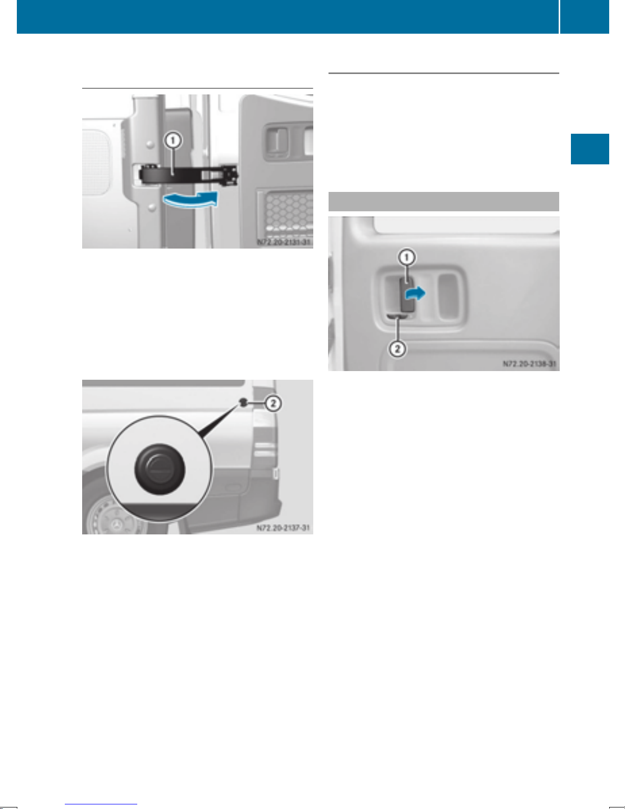
Rear doors
69
Opening the rear doors to an angle of
180° or 270°
Door retainer (example: right rear door)
X
Open the rear door to about 45°.
X
Pull and hold door retainer : in the direction
of the arrow.
X
Open the rear door more than 90°, so that the
door retainer cannot engage.
X
Release the door retainer and open the door
to an angle of 180° or 270°.
Closing the rear doors from the outside
X
Pull the rear door away from magnetic door
retainer.
X
Close the left-hand rear door firmly from the
outside.
X
Close the right-hand rear door firmly from the
outside.
Opening/closing from the inside
Opening and closing
Magnetic door retainer
X
With the rear door opened to an angle of
270°, push it against magnetic door
retainer ; on the side wall.
When the magnet on the rear door is in contact with magnetic door retainer ;, the rear
door is held in this position.
Vehicles with 270° pivoting rear doors:
i
If door retainer : malfunctions while loading,
you can swivel it 180° against the spring force
and onto the door and engage it. The door
retainer remains in this position and will not
swivel back to its original position.
Before closing the door, release door
retainer : from the detent and return it to its
original position.
Release the lever on the inside of the right rear door
A white section on latch ; indicates that the
rear door is unlocked.
You can only open the locked rear doors
i
from the inside if the child-proof locks have
not been activated.
X
To unlock: slide latch ; to the left.
You will see a white marking.
Only the rear door unlocks. All other doors
that were previously locked remain locked.
X
To open: pull opening lever : and open the
unlocked rear door.
X
Swing the rear door to the side until it
engages.
X
To close: make sure that the left-hand rear
door is closed.
X
Pull the rear door firmly by the door handle to
close it.
X
To lock: slide latch ; to the right.
The white section is no longer visible.
Only the rear door is locked. All other doors
that were previously unlocked remain
unlocked.
Z
Page 72
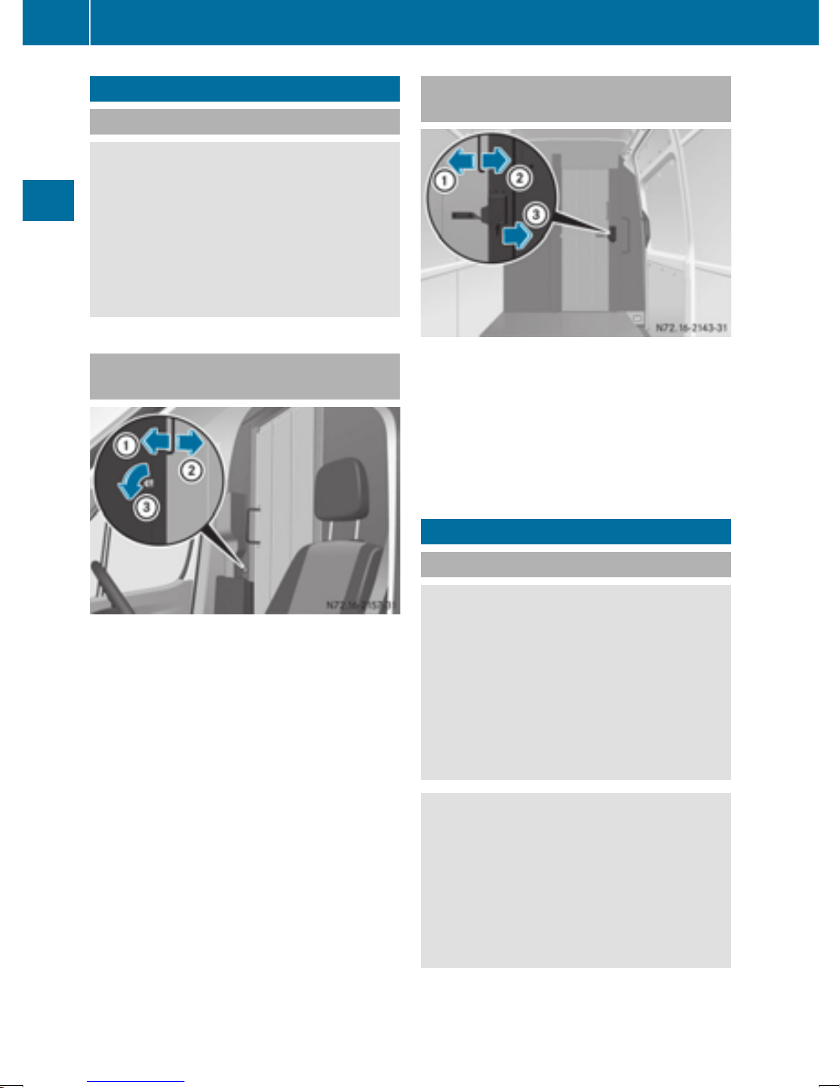
70
Side windows
Partition sliding door
Important safety notes
WARNING
G
If the open partition sliding door is not
engaged, it could move automatically while
the vehicle is in motion. This could trap you or
other persons. There is a risk of an accident
and injury.
Close the partition sliding door before every
journey and make sure that it is engaged.
Opening/closing the partition sliding
door from the cab
Opening and closing
Opening/closing the partition sliding
door from the cargo compartment
X
To unlock: press the catch in the direction of
arrow =.
The sliding door is unlocked.
X
Slide the sliding door to the stop in the direction of arrow :.
X
To close: slide the sliding door in the direction of arrow ; until it engages.
X
To open: turn the key counter-clockwise =.
The sliding door is unlocked.
X
Slide the sliding door to the stop in the direction of arrow ;.
X
To close: slide the sliding door in the direction of arrow : until it engages.
The sliding door can be locked using the key.
Side windows
Important safety notes
WARNING
G
While opening the side windows, body parts
could become trapped between the side window and the door frame as the side window
moves. There is a risk of injury.
Make sure that nobody touches the side window during the opening procedure. If somebody becomes trapped, release the switch or
pull the switch to close the side window again.
WARNING
G
While closing the side windows, body parts in
the closing area could become trapped. There
is a risk of injury.
When closing make sure that no parts of the
body are in the closing area. If somebody
becomes trapped, release the switch or press
the switch to open the side window again.
Page 73
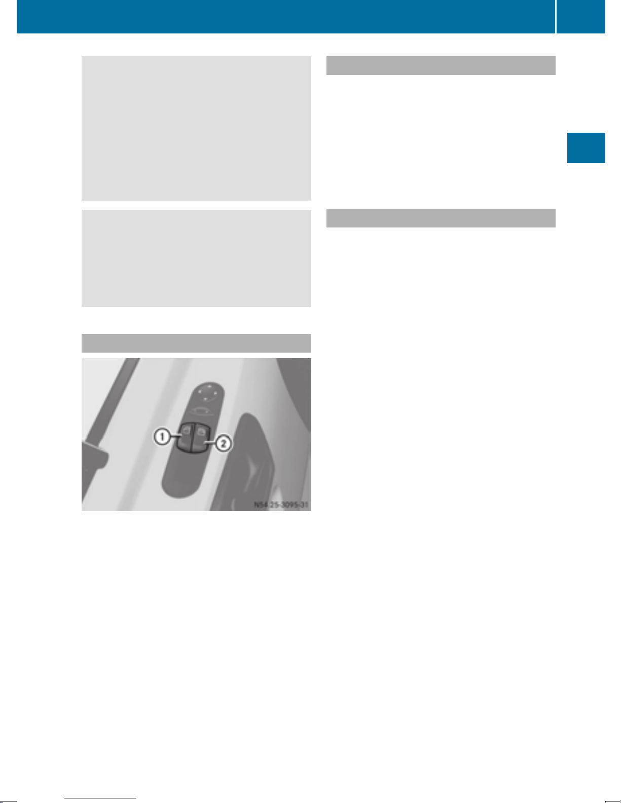
Side windows
71
WARNING
G
If children operate the side windows they
could become trapped, particularly if they are
left unsupervised. There is a risk of injury.
Activate the override feature for the rear side
windows. When leaving the vehicle, always
take the SmartKey with you and lock the vehicle. Never leave children unsupervised in the
vehicle.
WARNING
G
If persons, particularly children are subjected
to prolonged exposure to extreme heat or
cold, there is a risk of injury, possibly even
fatal. Never leave children unattended in the
vehicle.
Opening/closing the side window
Resetting the side windows
You must reset the side windows if there has
been a malfunction or an interruption in the voltage supply.
X
Turn the key to position 2 in the ignition lock.
X
Pull the two power window switches and hold
for approximately 1 second after closing the
side window.
Problems with the side windows
If you cannot completely open or close a side
window:
If there are no objects or leaves in the window
guide that prevent the sliding sunroof from closing, there has been a malfunction or the onboard voltage has been interrupted.
X
Reset the side window (Y page 71).
Opening and closing
Control panel (example: driver's door)
:
Power window, left
;
Power window, right
X
Turn the key to position 2 in the ignition lock.
X
Press or pull button : or ; until the corresponding side window has reached the
desired position.
If you press the switch beyond the pressure
point and then release it, the window opens
automatically. To stop the movement, press or
pull the switch again.
Z
Page 74

72
Seats
Useful information
This Operator's Manual describes all models as
well as standard and optional equipment of your
vehicle that were available at the time of going
to print. Country-specific variations are possible. Note that your vehicle may not be equipped
with all of the described functions. This also
applies to systems and functions relevant to
safety.
Read the information on qualified specialist
workshops (
Y page 26).
Seats
Important safety notes
WARNING
G
You could lose control of your vehicle if you do
the following while driving:
R
adjust the driver's seat, head restraint,
steering wheel or mirrors
R
fasten the seat belt
There is a risk of an accident.
rest to an almost vertical position. When braking or in the event of an accident, you could
slide underneath the seat belt and sustain
abdomen or neck injuries, for example. This
poses an increased risk of injury or even fatal
injury.
Adjust the seat properly before beginning
your journey. Always ensure that the backrest
is in an almost vertical position and that the
shoulder section of your seat belt is routed
across the center of your shoulder.
WARNING
G
If head restraints are not installed and adjusted correctly, they cannot provide protection
as intended. There is an increased risk of
injury in the head and neck area, e.g. in the
event of an accident or when braking.
Always drive with the head restraints installed. Before driving off, make sure for every
vehicle occupant that the center of the head
restraint supports the back of the head at
about eye level.
Adjust the driver's seat, head restraint, steering wheel and mirror and fasten your seat belt
before starting the engine.
Seats, steering wheel and mirrors
WARNING
G
If the driver's seat is not engaged, it could
move unexpectedly while the vehicle is in
motion. This could cause you to lose control of
the vehicle. There is a risk of an accident.
Always make sure that the driver's seat is
engaged before starting the engine.
WARNING
G
When you adjust a seat, you or other vehicle
occupants could become trapped, e.g. on the
seat guide rail. There is a risk of injury.
Make sure when adjusting a seat that no one
has any body parts in the sweep of the seat.
WARNING
G
The seat belt does not offer the intended level
of protection if you have not moved the back-
Your seat must be adjusted in such a way that
you can wear the seat belt correctly.
Observe the following points:
R
Position the backrest in an almost vertical
position so that you are sitting virtually
upright. Do not drive with the backrest
reclined too far back.
R
Your arms should be slightly bent when you
are holding the steering wheel.
R
Avoid seat positions that prevent the seat belt
from being routed correctly. The shoulder
section of the belt must be routed over the
middle of your shoulder and be pulled tight
against your upper body. The lap belt must
always pass across your lap as low down as
possible, i.e. over your hip joints.
R
Adjust the head restraint so that it supports
the back of the head at eye level.
R
The distance from the pedals should be such
that you can depress them fully.
If you swap over the head restraints for the front
and rear seats, you will not be able to adjust the
height and angle of the head restraints to the
correct position.
Page 75
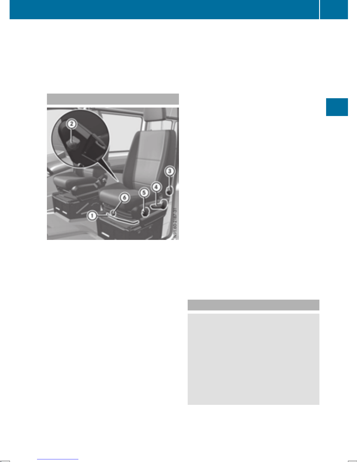
Seats
73
Use the head restraint pad to adjust the head
restraint so that it is as close as possible to the
back of your head.
Before the journey, make sure the head
restraints have been correctly set for each of the
vehicle's passengers (
Y page 76).
Driver's and front-passenger seat
X
To adjust the seat height: press or pull
lever ? repeatedly until you have reached
the desired seat height.
X
To adjust the seat angle: turn handwheel A
towards the front.
The front of the seat cushion is lowered.
X
Turn handwheel A towards the rear.
The front of the seat cushion is raised.
The lumbar support allows you to use the
i
backrest to increase the support provided to
the lumbar spine.
When the lumbar support is correctly adjusted, it reduces strain on your back while driving.
X
To adjust the lumbar support: turn handwheel ; upwards.
This increases the support provided to the
lumbar region.
X
Turn handwheel ; downwards.
This reduces the support provided to the lumbar region.
:
Seat fore-and-aft adjustment
;
Lumbar support adjustment
=
Seat backrest adjustment
?
Seat height adjustment
A
Seat cushion angle adjustment
B
Seat suspension adjustment
Depending on the seat model, some adjust-
i
ments may not be available.
You can find information on rotating the front
seats under "Swiveling front seats"
Y page 73).
(
To adjust the seat fore-and-aft position:
X
pull lever : up.
X
Slide the seat forwards or back.
X
Release lever :.
X
Slide the seat forwards or back until you hear
it engage.
X
To adjust the backrest: turn handwheel =
towards the front.
The seat backrest moves to a vertical position.
X
Turn handwheel = towards the rear.
The seat backrest tilts towards the rear.
The seat suspension must be adapted to your
body weight. Adjust the seat suspension only
while the seat is unoccupied.
X
To adjust the seat suspension: take your
weight off the seat.
X
Using handwheel B, set your body weight
(40 to 120 kg) for optimum seat suspension.
The seat suspension will become more rigid
the higher you set the weight. It will then not
move as far.
Swiveling front seats
WARNING
G
If the driver's and front-passenger seats are
not engaged facing the direction of travel
while driving, the restraint systems may not
be able to provide the intended protection.
There is an increased risk of injury, possibly
even fatal.
Engage the driver's and front-passenger seats
so they are facing the direction of travel
before starting the engine.
When rotating the seats, make sure that
!
there is sufficient space to do so.
Seats, steering wheel and mirrors
Z
Page 76
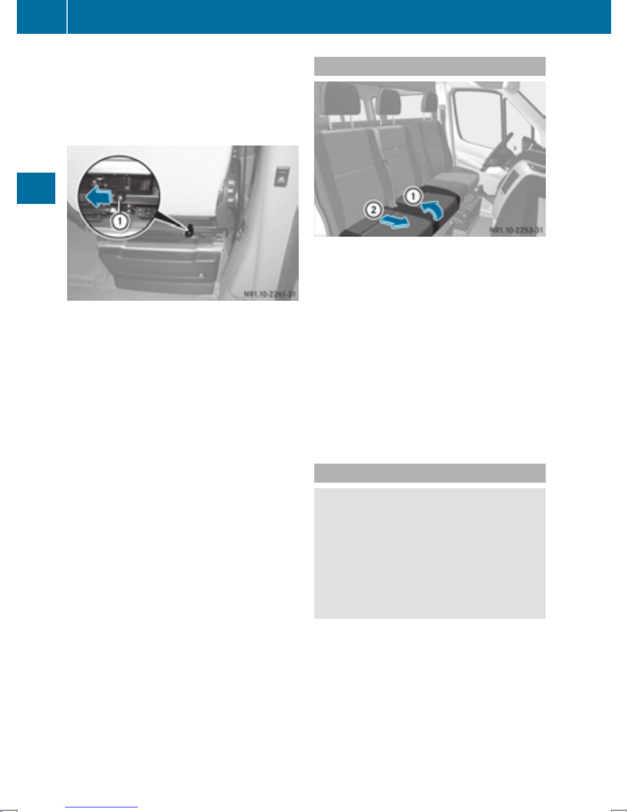
74
Seats
Move the seat forward or back first. This will
help to avoid contact with other parts of the
interior.
Push the handbrake lever down to the stop.
The parking brake or handbrake lever could
otherwise be damaged.
Seat release (example: front-passenger seat)
The driver's seat and front-passenger seat can
be rotated by 50° and 180°.
The seats engage when facing in the direction of
travel as well as when facing in the opposite
direction and also engage at an angle of 50° to
the door.
X
Make sure that the parking brake has been
engaged and that the handbrake lever has
been pushed down to the stop (
X
Adjust the steering wheel to provide the nec-
Seats, steering wheel and mirrors
essary space to rotate and adjust the driver's
Y page 77).
seat (
X
Before rotating, push the front-passenger
seat forwards (
X
To rotate the seat: push lever : on the rear
Y page 73).
Y page 131).
of the seat towards the center of the vehicle
and rotate the seat slightly inwards.
The rotation device is released.
X
Release lever :.
X
Turn the seat about 50° towards the outside
or inside to the desired position.
Twin front-passenger seat
X
To fold a seat cushion forwards: lift the seat
cushion out of front anchorage :.
X
Pull the seat cushion forwards slightly and out
of rear anchorage ;.
X
Fold the rear edge of the seat cushion up.
You can stow various articles in the space
i
under the twin front-passenger seat.
X
To fold the seat cushion back: fold down
the seat cushion by the rear edge.
X
Slide the seat cushion under the seat backrest into rear anchorage ;.
X
Push down on the seat cushion at the front
until it engages in front anchorage :.
Folding seat
WARNING
G
If the key is inserted in the partition sliding
door, it may come into contact with the person on the folding seat. There is a risk of
injury.
Always remove the key from the partition sliding door before a person sits on the folding
seat.
Page 77
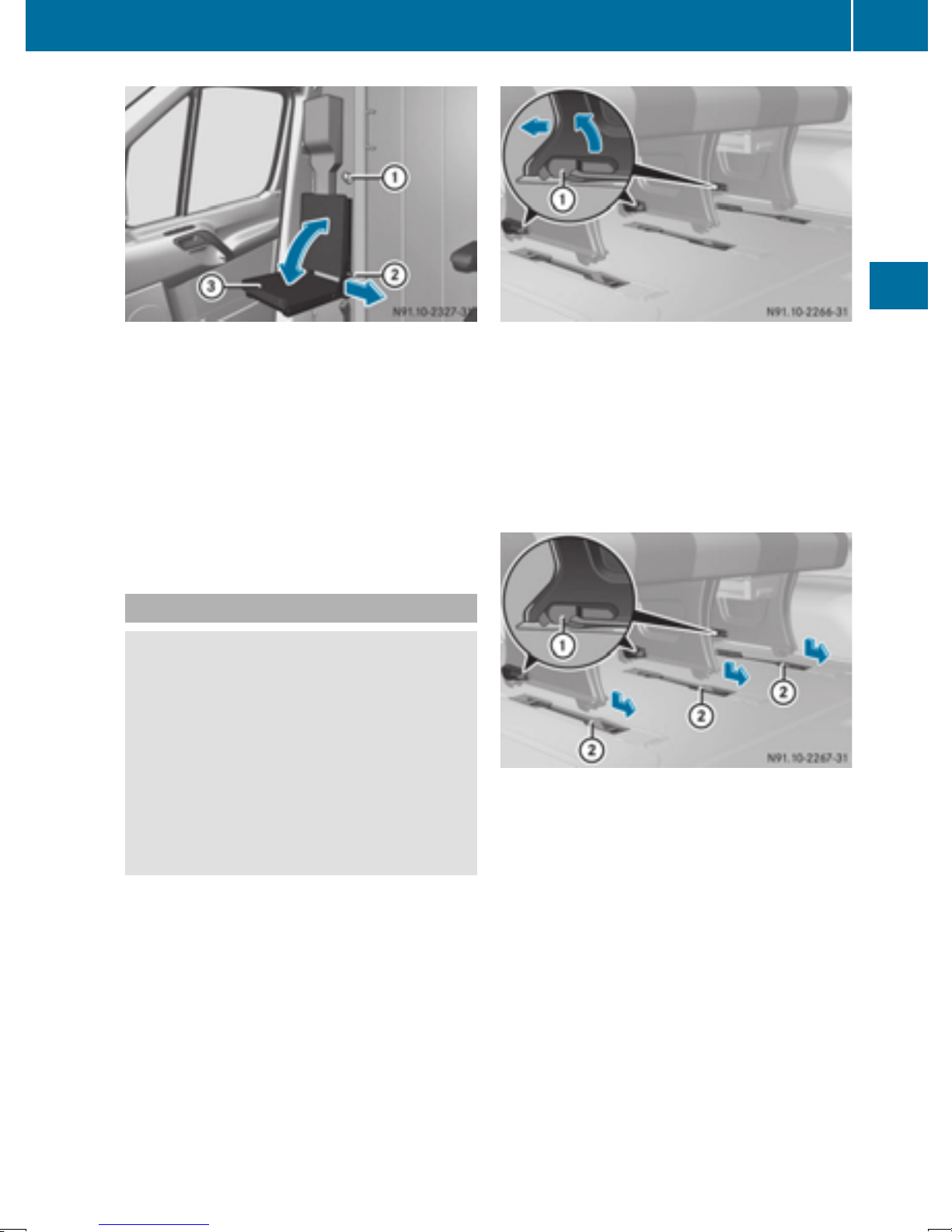
Seats
75
Folding seat (example with partition sliding door)
X
Remove key : from the partition sliding
door.
X
Pull grip ; of the catch in the direction of the
arrow and fold seat cushion = up or down.
X
Release grip ; of seat cushion = in the corresponding end position.
X
Move the seat cushion = until it engages.
Grip ; of the catch must lie completely on
the seat frame.
Rear bench seat (Passenger Van)
WARNING
G
If the rear bench seat is not installed as described or an unsuitable rear bench seat is installed, the seat belts may not provide protection
as intended. There is an increased risk of
injury.
Install the rear bench seat as described. Only
use rear bench seats that are approved for
your vehicle by the distributor named on the
inside cover page.
For safety reasons, the four-seat rear bench
!
must only be removed or installed at a qualified specialist workshop.
Keep the seat bench mounting recesses in the
vehicle floor free from dirt and foreign objects.
Locking mechanism lever on the feet of the bench
seat
X
To remove the rear bench seat: swing all
levers : of the bench seat completely
upwards.
The bench seat moves back into the seat
mounting recesses on the vehicle floor.
X
Lift the bench seat upwards out of the seat
mounting recesses.
Do not exceed the maximum permissible
i
number of seats for models registered as
passenger vehicles.
X
To install the rear bench seat: observe the
prescribed installation position of the bench
seat.
Install the two-seat bench seat only on the
driver's side.
X
Check mounting shells ; on the vehicle
floor.
X
Position the bench seat in the direction of
travel in corresponding mounting shells ;.
X
Slide the bench seat forwards until you hear
the locking mechanisms engage.
X
Check levers : on the anchorages of the
bench seat.
All levers : must be flush to the vehicle floor.
Seats, steering wheel and mirrors
Z
Page 78
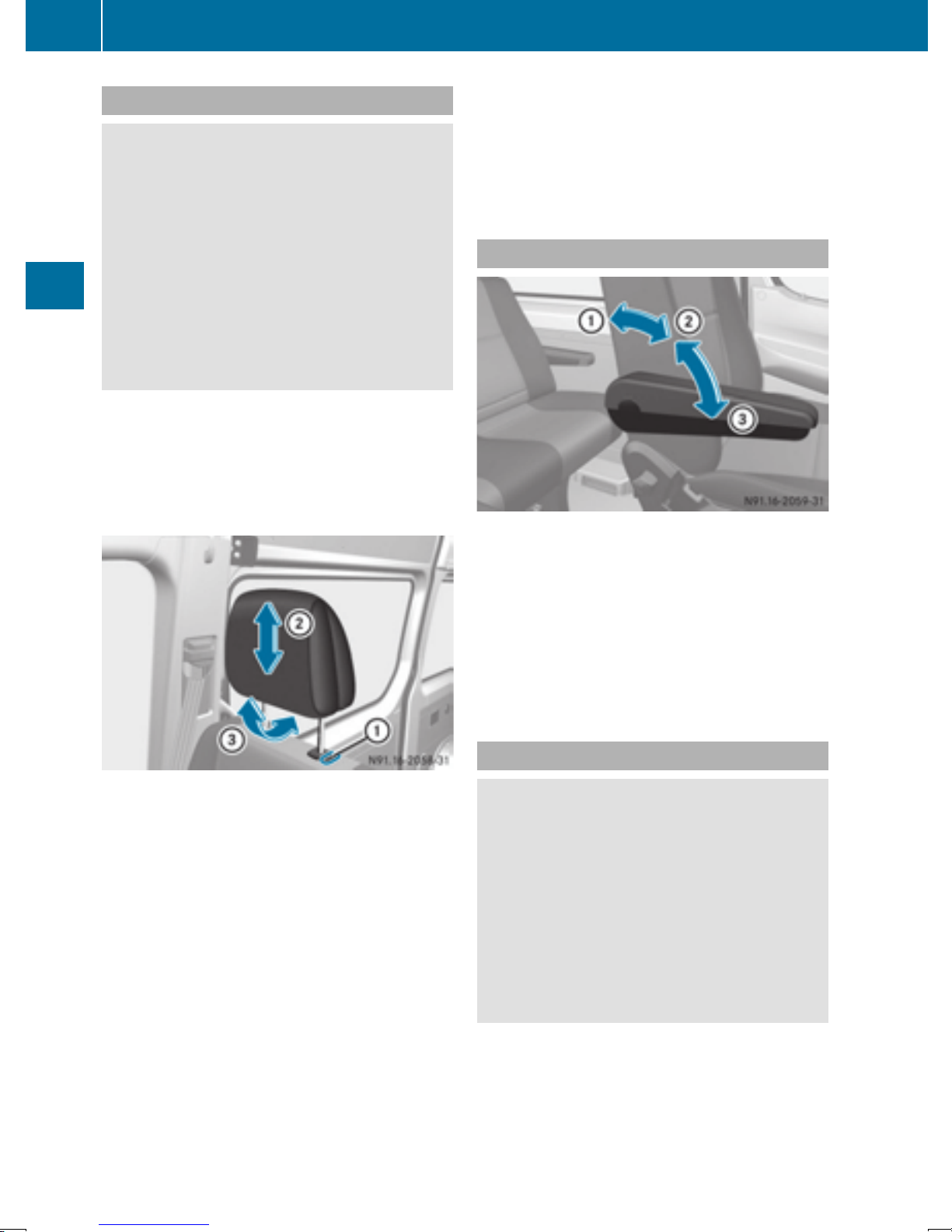
76
Seats
Head restraints
WARNING
G
If head restraints are not installed and adjusted correctly, they cannot provide protection
as intended. There is an increased risk of
injury in the head and neck area, e.g. in the
event of an accident or when braking.
Always drive with the head restraints installed. Before driving off, make sure for every
vehicle occupant that the center of the head
restraint supports the back of the head at
about eye level.
Do not change over the head restraints for the
front and rear seats. Otherwise, it will not be
possible to correctly adjust the height and angle
of the head restraints.
Adjust the head restraint so that it is as close as
possible to your head.
Seats, steering wheel and mirrors
X
To insert: insert the head restraint so that the
rod with the detents is on the left when viewed
in the direction of travel.
X
Press and hold release button :.
X
Push the head restraint down until it engages.
Armrests
X
To set the armrest angle: fold the armrest
upwards by more than 45° ;.
The armrest is released.
X
Fold armrest = forwards to the stop.
X
Slowly fold the armrest upwards to the
desired position.
X
To fold the armrest up: if necessary, fold the
armrest upwards : by more than 90°.
Head restraint (example: luxury head restraint on
the front-passenger seat)
:
Release button
;
Head restraint height
=
Head restraint angle (luxury head restraints
only)
X
To raise: pull the head restraint up to the
desired position.
X
To lower: press release button : and slide
the head restraint down to the desired position.
X
To adjust the angle: hold the front part of the
luxury head restraint by the lower edge and
tilt it to the desired position.
X
To remove: pull the head restraint up to the
stop.
X
Press release button : and pull out the head
restraint.
Seat heating
WARNING
G
Repeatedly switching on the seat heating can
cause the seat cushion and backrest pads to
become very hot. The health of persons with
limited temperature sensitivity or a limited
ability to react to excessively high temperatures may be affected or they may even suffer
burn-like injuries. There is a risk of injury.
Therefore, do not switch the seat heating on
repeatedly.
When you leave your seat, do not place any-
!
thing on the seat and switch off the seat heating. Do not switch the seat heating on when
the seat is not occupied, e.g. when driving
without a front passenger. The seat heating
may otherwise overheat, causing damage to
the seat.
Page 79
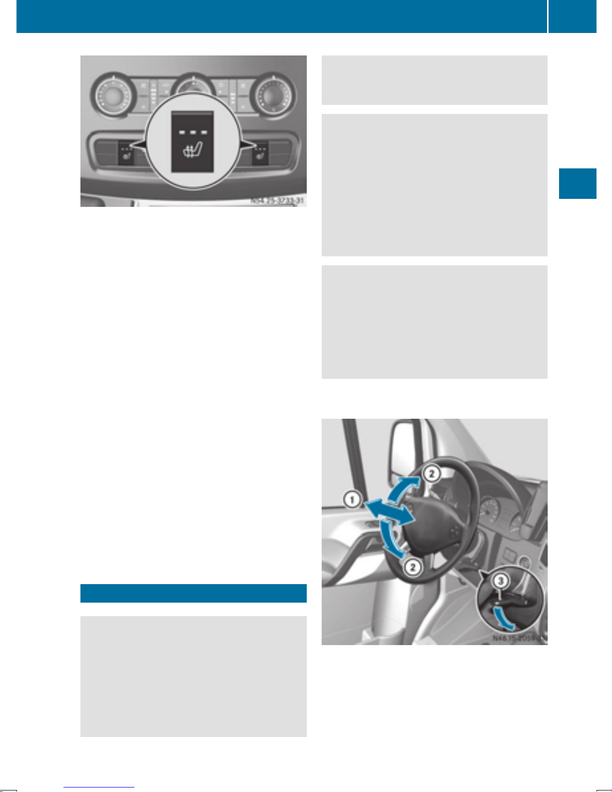
Steering wheel
Adjust the driver's seat, head restraint, steering wheel and mirror and fasten your seat belt
before starting the engine.
WARNING
G
If the steering wheel is unlocked while the
vehicle is in motion, it could change position
unexpectedly. This could cause you to lose
control of the vehicle. There is a risk of an
accident.
77
The three red indicator lamps in the c button
show the activated heating level 1 to 3.
The system automatically switches down from
level 3 to level 2 after approximately
five minutes.
The system automatically switches down from
level 2 to level 1 after approximately
ten minutes.
At level 1, the seat heating remains in continuous operation.
X
Make sure that the key is in position 1 or 2 in
the ignition lock.
X
To switch on: press the c button repeat-
edly until the desired heating level has been
set.
X
To switch off: press the c button repeat-
edly until all indicator lamps go out.
If the indicator lamps of the current heating level
in the c button flash, the seat heating has
switched off automatically. In this case, too
many electrical consumers are switched on or
the battery charge is not sufficient. The seat
heating will automatically switch back to the
current heating level when enough on-board
voltage is available again.
Before starting off, make sure the steering
wheel is locked. Never unlock the steering
wheel while the vehicle is in motion.
WARNING
G
Children could injure themselves if they
adjust the steering wheel. There is a risk of
injury.
When leaving the vehicle, always take the
SmartKey with you and lock the vehicle. Never
leave children unsupervised in the vehicle.
The steering wheel can still be adjusted if the
key has been removed.
Seats, steering wheel and mirrors
Steering wheel
WARNING
G
You could lose control of your vehicle if you do
the following while driving:
R
adjust the driver's seat, head restraint,
steering wheel or mirrors
R
fasten the seat belt
There is a risk of an accident.
:
Steering column fore-and-aft adjustment
;
Steering column height
=
Lever
Z
Page 80
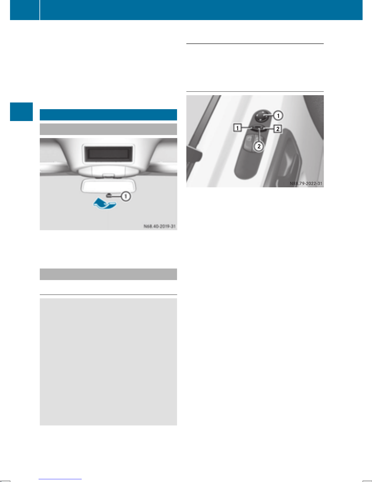
78
Mirrors
X
To set the steering wheel: swing lever =
down until it engages.
The steering wheel is unlocked.
X
Move the steering wheel to the desired position.
X
Pull lever = up to the stop.
The steering wheel is locked again.
Mirrors
Rear-view mirror
Adjusting manually
X
Before starting off, manually adjust the exterior mirrors in such a way that you can get a
good overview of road and traffic conditions.
Adjusting electrically
X
Anti-glare mode: push anti-glare lever : in
the direction of the arrow.
Exterior mirrors
Seats, steering wheel and mirrors
Important safety notes
WARNING
G
The additional mirrors in the exterior mirrors
reduce the size of the image. Objects visible in
the mirrors are closer than they appear. You
could misjudge the distance from road users
driving behind you when changing lanes, for
instance. There is a risk of an accident.
You should therefore always determine the
actual distance from road users driving
behind you, e.g.:
Adjustment buttons and switches for setting the
mirrors
X
Before pulling away, turn the key to position 2
in the ignition lock (
X
Press switch ; to position 1 for the left-hand
Y page 119).
exterior mirror or to position 2 for the righthand exterior mirror.
X
Press adjustment button : at the top, bottom, right or left.
Adjust the exterior mirrors in such a way that
you can get a good overview of road and traffic conditions.
The exterior mirrors are automatically
i
heated at low outside temperatures.
R
by looking over your shoulder
R
by looking in the main mirror in the exterior
mirror.
Page 81
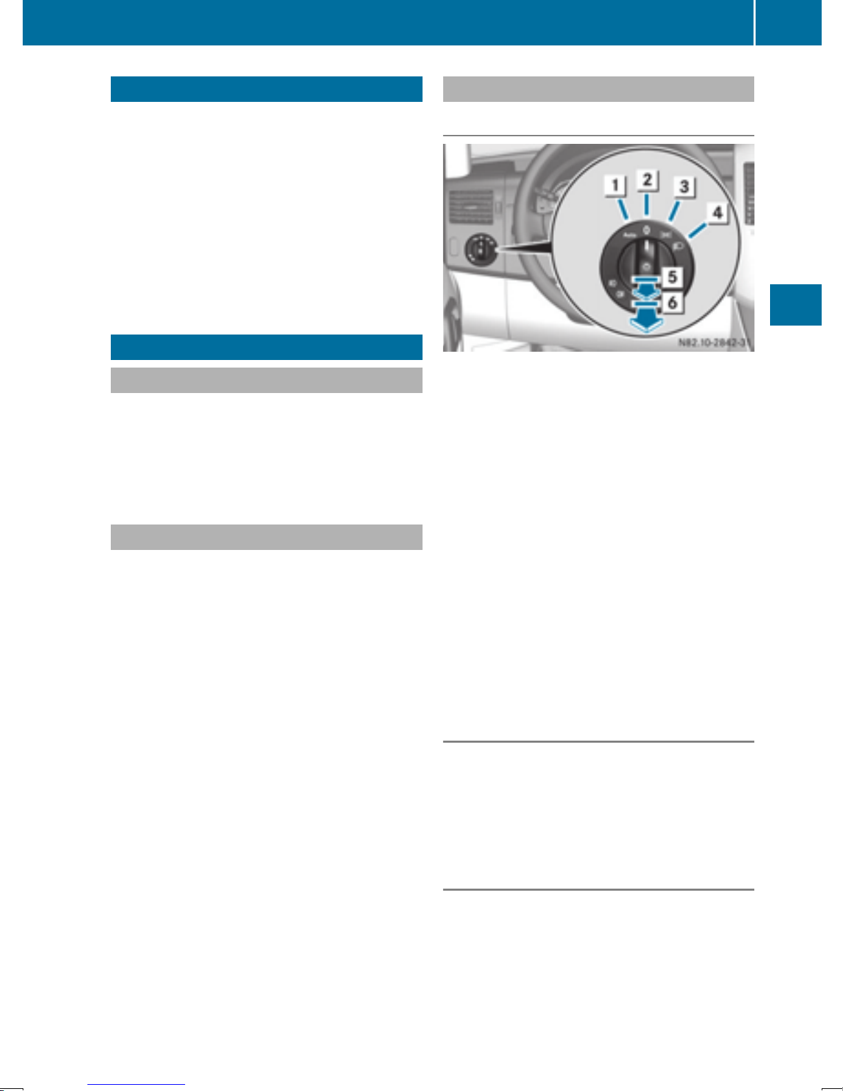
Exterior lighting
79
Useful information
This Operator's Manual describes all models as
well as standard and optional equipment of your
vehicle that were available at the time of going
to print. Country-specific variations are possible. Note that your vehicle may not be equipped
with all of the described functions. This also
applies to systems and functions relevant to
safety.
Read the information on qualified specialist
workshops (
Y page 26).
Exterior lighting
Important safety notes
For reasons of safety, we recommend that you
drive with the lights switched on even during the
daytime. There may be differences in operation
due to legal requirements and voluntary recommendations in some countries.
Light switch
Operation
1 Ã
2 $
3 T
4 L
5 N
6 R
Automatic headlamp mode/daytime
running lamps
Lights off
Parking lamps, license plate and
instrument lighting
Low-beam/high-beam headlamps
Fog lamps
Rear fog lamp
Bulb failure indicator
The bulb failure indicator is only an aid. You are
responsible for the proper functioning of the
vehicle lighting. Insufficient or non-functioning
vehicle lighting puts the operating safety of the
vehicle at risk.
For this reason, check the condition and function of your vehicle's lighting system and, if necessary, that of the trailer before each journey.
The bulb failure indicator monitors all of the
exterior lighting lamps, except the perimeter
lamp and the trailer lighting. If a bulb fails, either
the b(
you will see a corresponding message in the
display (
i
ure indicator can fail for all lamps with the
exception of the turn signal lamps.
Y page 33) indicator lamp lights up, or
Y page 185).
Depending on the equipment, the bulb fail-
If you hear a warning tone when you leave the
vehicle, the lights may still be switched on.
X
Turn the light switch to $ or Ã.
or
X
If the rear fog lamp is switched on: press the
light switch in to the stop.
The turn signals, high-beam headlamps and the
high-beam flasher are operated using the combination switch (
Y page 81).
Low-beam headlamps
X
To switch on: turn the key to position 2 in the
ignition lock or start the engine.
X
Turn the light switch to position L.
The L indicator lamp in the instrument
cluster lights up.
Daytime running lamps
You can activate/deactivate the daytime running lamps function using the on-board computer.
This is not possible in countries where daytime
running lamps are a legal requirement.
Lights and windshield wipers
Page 82

80
Exterior lighting
The daytime running lamps function must be
activated using the on-board computer:
R
vehicles with steering wheel buttons
Y page 171)
(
R
vehicles without steering wheel buttons
Y page 164)
(
X
To switch on: turn the light switch to the
$ position.
The low-beam headlamps, parking lamps and
license plate lamp are switched on when the
engine is running. The L indicator lamp in
the instrument cluster lights up.
USA only:
i
If you turn the light switch to the T or L
position, the parking lamps or low-beam
headlamps switch on. If you turn the light
switch to the à position, the daytime running lamps remain switched on.
Canada only:
i
If you turn the light switch to the L position, the low-beam headlamps are switched
on. If you turn the light switch to the T or
à position, the daytime running lamps
remain switched on.
To switch on automatic headlamp mode:
X
turn the light switch to Ã.
Key in position 1 in the ignition lock: the parking lamps switch on or off automatically
depending on the ambient light.
When the engine is running: if you activate the
"daytime running lamps" function using the
on-board computer, the daytime running
lamps are switched on. The parking lamps and
low-beam headlamps also switch on or off
automatically, depending on the ambient
light.
When the low-beam headlamps are switched
on, the L indicator lamp in the instrument
cluster lights up.
Fog lamps/rear fog lamp
WARNING
G
If you suspect that driving conditions will be
foggy, turn the light switch to L before you
start your journey. Your vehicle may otherwise not be visible and you could endanger
yourself and others.
Automatic headlamp mode
WARNING
G
When the light switch is set to Ã, the low-
Lights and windshield wipers
beam headlamps may not be switched on
automatically if there is fog, snow or other
causes of poor visibility due to the weather
conditions such as spray. There is a risk of an
accident.
In such situations, turn the light switch to
L.
Automatic headlamp mode is only a driving aid.
You are responsible for the vehicle lighting at all
times.
Depending on ambient light, the rain and light
sensor automatically switches on the parking
lamps, low-beam headlamps and the license
plate lamp. This excludes weather-related
impairments to visibility, such as snow, fog or
spray.
If there is fog, snow or spray, turn the light
switch quickly from à to L. You could
otherwise briefly interrupt operation of the
headlamps.
WARNING
G
In low ambient lighting or foggy conditions,
only switch from position à to L with
the vehicle at a standstill in a safe location.
Switching from à to L will briefly
switch off the headlamps. Doing so while driving in low ambient lighting conditions may
result in an accident.
X
Turn the ignition key to position 2 in the ignition lock or start the engine.
X
Turn the light switch to L or T.
If your vehicle is only equipped with one rear
i
fog lamp, you must turn the light switch to
L.
When the light switch is set to à you
i
cannot switch on the front and rear foglamps.
X
To switch on the front fog lamps: pull the
light switch out to the first locking point.
The green N indicator lamp on the light
switch lights up.
Page 83
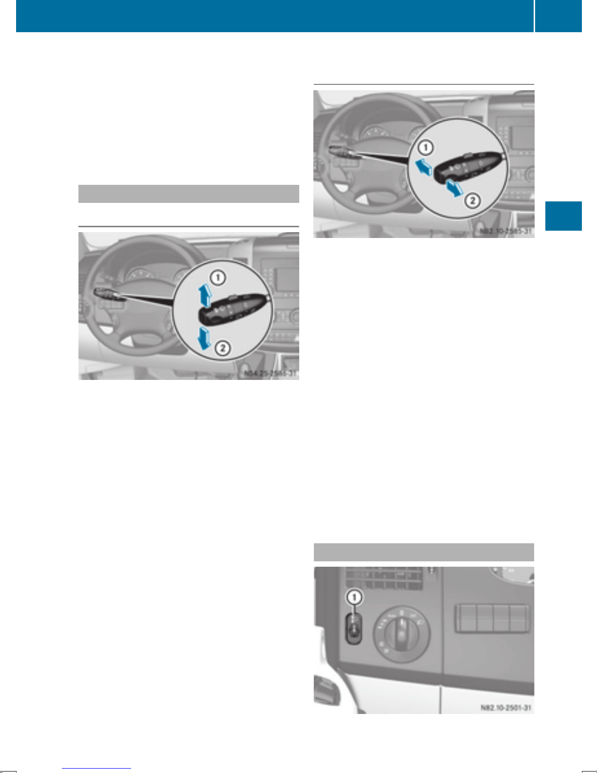
X
To switch on the rear fog lamp: pull the light
switch out to the second locking point.
The yellow R indicator lamp on the light
switch lights up.
To switch off the front and rear foglamps:
X
push in the light switch to the stop.
The R and N indicator lamp on the light
switch go out.
Combination switch
Turn signal lamps
:
To indicate a right turn
;
To indicate a left turn
X
To indicate: press the combination switch in
desired direction : or ; until it engages.
The combination switch automatically returns
to its original position after large steering
movements.
X
To indicate briefly: press the combination
switch briefly in desired direction : or ;.
The corresponding turn signal flashes three
times.
Exterior lighting
High-beam headlamps and high-beam
flasher
:
High-beam headlamps
;
High-beam flasher
To switch on the high-beam headlamps:
X
switch on the low-beam headlamps
Y page 79).
(
X
Press combination switch : forwards.
The K indicator lamp in the instrument
cluster lights up.
In the à position, the high-beam head-
i
lamps are only switched on when it is dark and
the engine is running.
To switch off the high-beam headlamps:
X
move the combination switch back to its normal position.
The K indicator lamp in the instrument
cluster goes out.
X
To switch on the high-beam flasher: turn
the key to position 1 or 2 in the ignition lock.
X
Pull the combination switch briefly in direction of arrow ;.
81
Lights and windshield wipers
Headlamp range adjustment
Z
Page 84
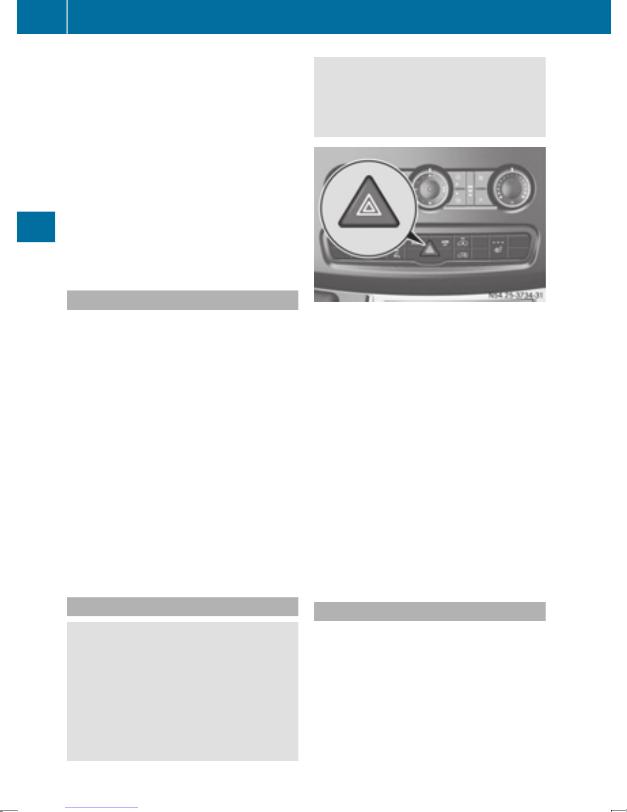
82
Exterior lighting
The headlamp range control is used to adapt the
downward angle of the headlamp beams in
accordance with the load on your vehicle. The
cone of light from the headlamps changes if
seats are occupied or if the cargo compartment
is being loaded or unloaded. This can impair visibility and cause glare to oncoming traffic.
You can only adjust the headlamp range while
the engine is running.
X
Turn headlamp range control : to the corresponding position. The road ahead should
be lit up for 40 mto 100 mand the low-beam
headlamps should not cause glare to oncoming traffic.
Select position g if the vehicle is unladen.
Cornering lamps
The cornering lamps improve the illumination of
the road over a wide angle in the direction you
are turning, enabling better visibility in tight
bends, for example.
The cornering light function switches on
automatically, if:
R
you are traveling at a speed of less than
25 mph (40 km/h) and you switch on a turn
signal or turn the steering wheel.
R
you are traveling at a speeds of between
25 mph (40 km/h) and 43 mph (70 km/h) and
Lights and windshield wipers
turn the steering wheel.
The cornering lamp may remain lit for a short
time, but is automatically switched off after no
more than 3 minutes.
If reverse gear is engaged the lamp on the
i
opposite side of the vehicle switches on
instead.
You should therefore ensure in this and similar situations that the vehicle is visible from
the rear in accordance with the relevant
national regulations, by using the warning triangle, for instance.
Hazard warning lamp switch
X
To switch on/off: press the £ hazard
warning lamp switch.
If you have indicated a turn while the hazard
warning lamps are switched on, only the turn
signal lamps on the side of the vehicle selected
will light up.
The hazard warning lamps switch on automatically if:
R
an air bag is deployed.
R
you brake sharply and bring the vehicle to a
halt from a speed of more than 45 mph
(70 km/h).
If the hazard warning lamps have been switched
on automatically, press the £ hazard warning lamp switch to switch them off.
The hazard warning lamps work even when
i
the ignition is switched off.
Hazard warning lamps
WARNING
G
The rear exterior light will be covered if you:
R
open the rear doors by 90°
R
open the rear dropside.
The vehicle will then be difficult for other road
users to see or will not be seen by them at all,
particularly if it is dark or visibility is poor.
There is a risk of an accident.
Headlamp cleaning system
The headlamps are cleaned automatically with a
high-pressure water jet if the "Wipe with washer
fluid" function is activated (
the low-beam headlamps are on and the engine
is running.
You can find information on refilling washer fluid
in the "Maintenance and care" section
Y page 224).
(
Y page 93) while
Page 85
Exterior lighting
83
Highbeam Assist
General notes
You can use this function to set the headlamps
to change between low beam and high beam
automatically. The system recognizes vehicles
with their lights on, either approaching from the
opposite direction or traveling in front of your
vehicle, and consequently switches the headlamps from high beam to low beam.
Once the system no longer detects any other
vehicles, it reactivates the high-beam headlamps.
The system's optical sensor is located behind
the windshield near the overhead control panel.
Important safety notes
WARNING
G
Highbeam Assist does not recognize road
users:
R
who have no lights, e.g. pedestrians
R
who have poor lighting, e.g. cyclists
R
whose lighting is blocked, e.g. by a barrier
In very rare cases, Highbeam Assist may fail to
recognize other road users who have lights, or
may recognize them too late. In this or similar
situations, the automatic high-beam headlamps will not be deactivated or will be activated regardless. There is a risk of an accident.
Always carefully observe the traffic conditions
and switch off the high-beam headlamps in
good time.
Activating/deactivating Highbeam
Assist
X
To activate: switch on the Highbeam Assist
function using the on-board computer
Y page 171).
(
X
Turn the light switch to the à position.
X
Press the combination switch beyond the
pressure point in the direction of arrow :
Y page 81).
(
Highbeam Assist is active.
The _ or
multifunction display lights up when it is dark
and the light sensor activates the low-beam
headlamps.
If you are driving at speeds above approximately 22 mph (35 km/h) and no other road
users have been detected:
The high-beam headlamps are switched on
automatically. The K indicator lamp in the
instrument cluster also lights up.
If you are driving at speeds below approximately 19 mph (30 km/h), other road users
are recognized or the roads are adequately lit:
The high-beam headlamps are switched off
automatically. The K indicator lamp in the
instrument cluster goes out. The _ or
indicator lamp in the multifunction
display remains lit.
X
To deactivate: move the combination switch
back to its normal position or move the light
switch to another position.
The _ or
multifunction display goes out.
indicator lamp in the
indicator lamp in the
Lights and windshield wipers
Highbeam Assist cannot take into account road,
weather or traffic conditions. Highbeam Assist
is only an aid. You are responsible for adjusting
the vehicle's lighting to the prevailing light, visibility and traffic conditions.
In particular, the detection of obstacles can be
restricted if there is:
R
poor visibility, e.g. due to fog, heavy rain or
snow
R
dirt on the sensors or anything else covering
the sensors
Headlamps fogged up on the inside
The headlamps may fog up on the inside if there
is high atmospheric humidity.
X
Switch on the low-beam headlamps and drive
off.
The level of moisture diminishes, depending
on the length of the journey and the weather
conditions (humidity and temperature).
If the level of moisture does not diminish:
X
Have the headlamps checked at a qualified
specialist workshop.
Z
Page 86
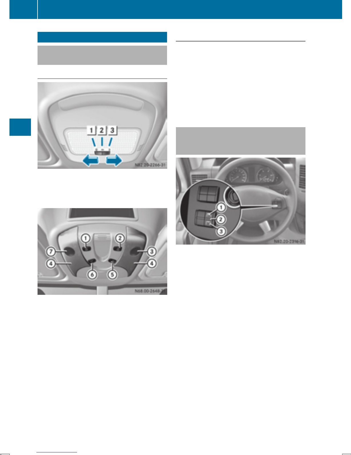
84
Interior lighting
Interior lighting
Switching the dashboard lighting on/
off
Overview
Standard interior light
1
Interior light switched on
2
Interior light switched off
3
Automatic control system switched on
Automatic control
The interior light comes on if you:
R
unlock the vehicle
R
open the driver's or the front-passenger door
R
remove the key from the ignition lock
The interior light switches off again automatically.
If a door is left open, the interior lighting
switches off after approximately 20 minutes.
Switching the rear compartment
lighting on/off centrally (Passenger
Van)
Lights and windshield wipers
Interior lights in the overhead control panel
:
Switches the left-hand reading lamp on/off
;
Switches the right-hand reading lamp
on/off
=
Right-hand reading lamp
?
Interior light
A
Switches the automatic control system on/
off
B
Switches the interior light on/off
C
Left-hand reading lamp
If you manually switch on the interior lighting or
reading lamps on the overhead control panel,
they switch off automatically after 20 minutes.
Rear compartment lighting switch
:
To switch on the rear compartment lighting
;
Automatic control
=
To switch off the rear compartment lighting
You can switch the rear compartment lighting
on/off centrally on Passenger Vans that are
equipped with convenience control.
There may also be a switch on the rear compartment lights that allows you to switch them
on/off separately. If you switch off rear compartment lighting =, the rear compartment
light is switched off, regardless of the position of
its own switch.
If you move the rear compartment lighting
switch to center position ;, the automatic control system is switched on. When you open a
door or unlock the vehicle, the rear compartment lighting then goes on automatically. Once
the doors are closed, it switches off automatically after 20 minutes.
Page 87
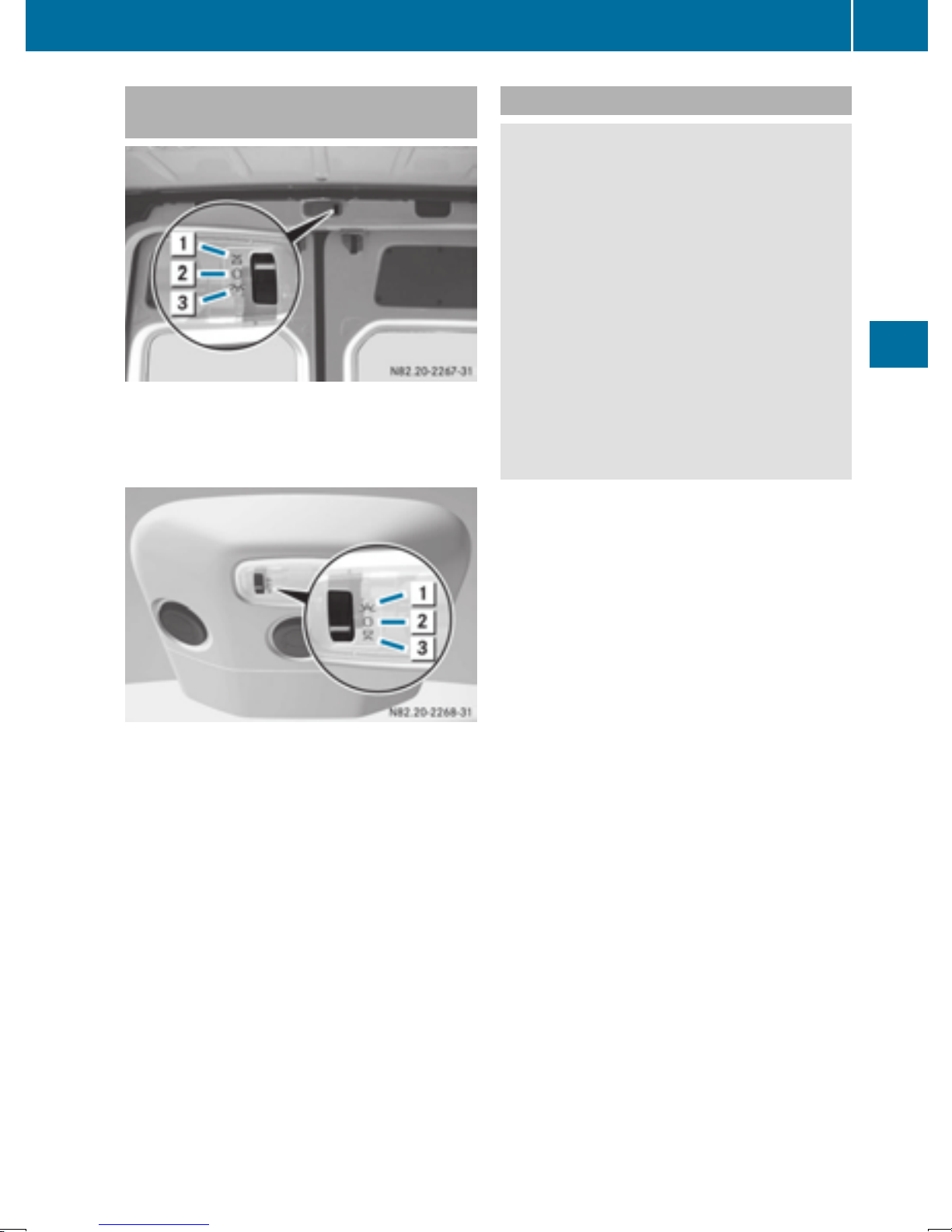
Interior lighting
85
Switching the rear/cargo compartment lamp on/off
Interior light with switch (example: Cargo Van)
1
Automatic control
2
To switch off the interior lighting
3
To switch on the interior lighting
Motion detector
WARNING
G
The motion detector sends the invisible infrared radiation emitted by LEDs (light emitting
diodes).
These LEDs are classified as class 1M lasers
and can damage the retina if you:
R
look directly into the unfiltered laser beam
of the motion detector for an extended
period
R
look directly into the laser beam of the
motion detector using optical instruments,
e.g. eyeglasses or a magnifying glass.
There is a risk of injury.
Never look directly into the motion detector.
The load compartment lighting is also switched
on by the motion detector in the load compartment on panel vans equipped with this feature.
If the motion detector detects a movement in
the cargo compartment when the vehicle is stationary, the cargo compartment lighting
switches on for approximately two minutes.
The cargo compartment lighting can be
switched on by the motion detector within
four seconds if:
Interior light with switch (example: Passenger Van
with rear-compartment air conditioning)
1
To switch on the interior lighting
2
To switch off the interior lighting
3
Automatic control
For Cargo Vans and Passenger Vans without
convenience control, the switch for the interior
lighting is on the rear interior light in the cargo
compartment/vehicle interior.
If you move the switch to automatic control, the
rear/cargo compartment lamps go on when you
open a door or unlock the vehicle. They switch
off automatically after 20 minutes, or when you
close the doors.
R
the rear interior light switch (Y page 84) is set
to automatic control.
R
the vehicle is stationary, the parking brake is
applied and the brake pedal is not being
depressed
or
R
the selector lever is in position P on vehicles
with automatic transmission and the brake
pedal is not being depressed and
R
the vehicle has not been locked from the outside using the key
The motion detector switches off automatically
if no change is detected in the vehicle for several
hours, e.g. if a door is opened, if the ignition key
is turned, etc. This prevents the battery from
becoming discharged.
Lights and windshield wipers
Z
Page 88
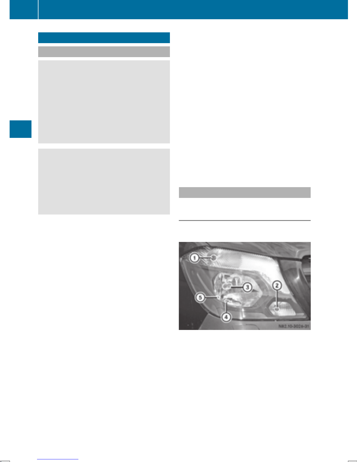
86
Changing bulbs
Changing bulbs
Important safety notes
DANGER
G
Xenon bulbs carry a high voltage. You can get
an electric shock if you remove the cover of
the Xenon bulb and touch the electrical contacts. There is a risk of fatal injury.
Never touch the parts or the electrical contacts of the Xenon bulb. Always have work on
the Xenon bulbs carried out at a qualified specialist workshop.
WARNING
G
Bulbs, lamps and connectors can get very hot
when operating. If you change a bulb, you
could burn yourself on these components.
There is a risk of injury.
Allow these components to cool down before
changing a bulb.
Make sure the bulbs are always securely
!
installed.
If your vehicle is equipped with Bi-Xenon bulbs,
you can recognize this by the following: the cone
of light from the Xenon bulbs moves from the
top to the bottom and back again when you start
Lights and windshield wipers
the engine. For this to be observed, the lowbeam headlamps must be switched on before
starting the engine.
The bulbs and lamps are an essential component of vehicle safety. You must therefore make
sure that these function correctly at all times.
Have the headlamp setting checked regularly.
R
Always switch off the vehicle's lighting system before changing a bulb.
This will prevent a short circuit.
R
Do not touch the glass tube of new bulbs with
your bare hands. Always use a clean, lint-free
cloth or only touch the base of the bulb when
installing.
Even minor contamination can burn into the
glass surface and reduce the service life of the
bulbs.
R
Do not use a bulb that has been dropped or
that has scratches on its glass tube.
The bulb could explode.
R
Only use bulbs in closed lamps which have
been designed for this purpose.
R
Only use spare bulbs of the same type and
with the prescribed voltage
R
Protect the bulbs from moisture when in use.
If the new bulb still does not light up, consult a
qualified specialist workshop.
R
Have the LEDs and bulbs of the following
lamps changed at a qualified specialist workshop:
-
the additional turn signals in the exterior
mirrors
-
the high-mounted brake lamp
-
LED daytime running lamps (Bi-Xenon
headlamps)
-
Bi-Xenon lamps (Bi-Xenon headlamps)
-
front fog lamps
If you require assistance changing bulbs, consult a qualified specialist workshop.
Front bulbs
Overview of bulb replacement – bulb
types
The following bulbs can be replaced. Bulb types
can be found in the legend.
Vehicles with halogen headlamps
:
Turn signal: PY21W
;
Daytime running lamps: W21W
=
Low-beam headlamps: H7 55W
?
High-beam headlamps: H7 55W
A
Parking lamps/standing lamps: W5W
Page 89
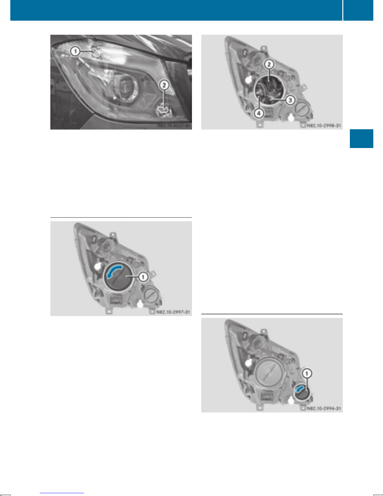
Changing bulbs
87
Vehicles with bi-xenon headlamps
:
Turn-signal: NAK 3457
;
Cornering light function: H7 55W
Vehicles with additional turn signals in the
exterior mirrors
Additional turn signal lamp: HPC 16WY
Low-beam headlamps and high-beam
headlamps/cornering lamp
Example (halogen headlamps)
;
Low-beam headlamp bulb holder
=
Bulb holder for high-beam headlamp
?
Bulb holder for parking lamp/standing lamp
(halogen headlamps)
X
Turn the corresponding bulb holder with
bulb ;, = or ? counter-clockwise and pull
it out of the lamp.
X
Pull the bulb out of the bulb holder.
X
Insert the new bulb in such a way that its base
fits into the recess of the bulb holder.
X
Insert the bulb holder with the bulb into the
lamp and turn it clockwise to tighten.
The bulb holder engages audibly.
X
Place housing cover : into the opening and
turn in the opposite direction of the arrow.
X
Close the hood.
Cornering light function/daytime running lamps
Lights and windshield wipers
Example (halogen headlamps)
X
Switch off the lighting system.
X
Open the hood (Y page 218).
X
Turn housing cover : in the direction of the
arrow and remove it.
X
Switch off the lighting system.
X
Open the hood (Y page 218).
X
Turn housing cover : counter-clockwise and
remove.
Z
Page 90
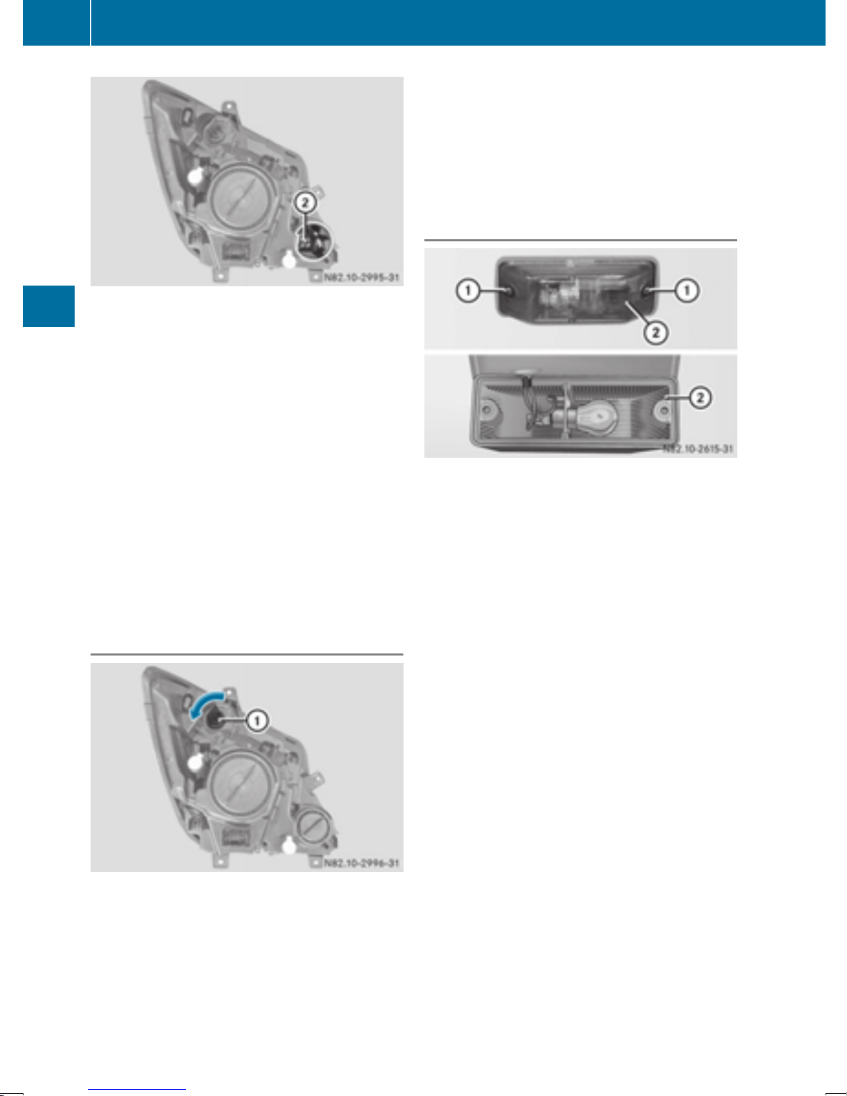
88
Changing bulbs
X
Bi-Xenon headlamps: turn bulb holder with
bulb ; counter-clockwise and remove it.
Halogen headlamps: press the spring
catches of the bulb holder together and
remove the bulb holder with bulb ;.
X
Pull the bulb out of the bulb holder.
X
Press a new bulb into the bulb holder.
X
Bi-Xenon headlamps: insert the bulb holder
with bulb ; into the lamp and turn clockwise.
Halogen headlamps: insert the bulb holder
with bulb ; into the lamp.
The bulb holder with bulb ; engages audibly.
X
Replace cap : and turn it clockwise to the
stop.
The cap audibly engages.
X
Close the hood (Y page 219).
Lights and windshield wipers
Turn signal lamps
X
Press the new bulb into bulb holder : and
screw it in clockwise.
X
Insert bulb holder : into the lamp and turn it
clockwise to tighten.
X
Close the hood.
Additional turn signal lamp (all-wheeldrive vehicles)
Additional turn signals (example: Cargo Van and
Passenger Van)
The additional turn signals are mounted on the
side of the vehicle's front wings.
X
Switch off the lighting system.
X
Undo screws : and remove lamp lens ;.
X
Applying light pressure to the bulb, turn it
counter-clockwise and remove it from the
bulb holder.
X
Press the new bulb into the bulb holder and
screw it in clockwise.
X
Position lamp lens ; and tighten screws :.
X
Switch off the lighting system.
X
Open the hood (Y page 218).
X
Turn bulb holder : counter-clockwise and
remove it.
X
Applying light pressure to the bulb, turn it
counter-clockwise and remove it from bulb
holder :.
Page 91
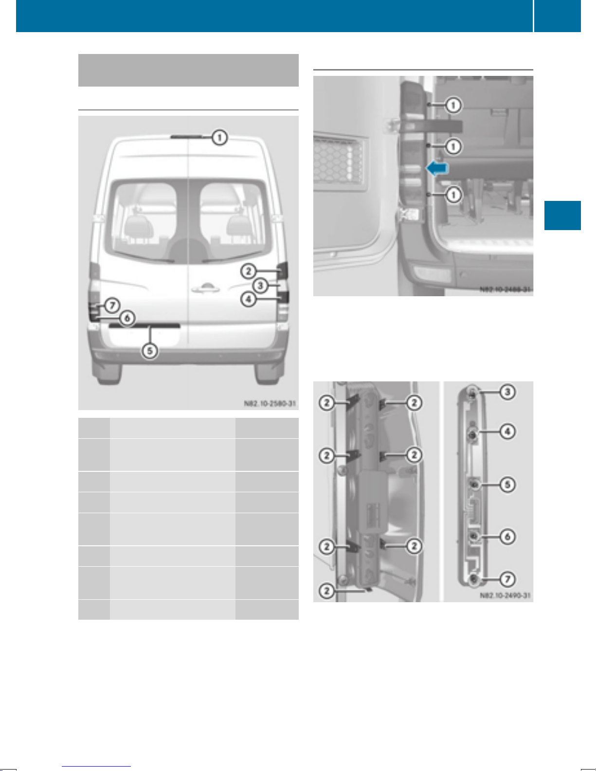
Changing bulbs
89
Rear bulbs (Cargo Van/Passenger
Van)
Overview of bulb types
Tail lamps
X
Switch off the lighting system.
X
Open the rear door.
X
Undo screws : and unclip the lamp lens in
the direction of the arrow.
X
Pull the connector off the bulb holder.
:
;
=
?
A
B
C
Lights Bulb type
High-mounted brake
LED
lamp
Brake lamp/tail lamp P21W/5W
Turn signal lamps PY 21 W
Tail lamps/standing
R5W
lamps
License plate lamp W5W
Rear fog lamps (driver's
P21W
side)
Backup lamps P21W
;
Retaining lugs
=
Brake lamps
?
Turn signal lamps
A
Standing lamp/tail lamp
B
Backup lamps
C
Rear fog lamp
Lights and windshield wipers
Z
Page 92
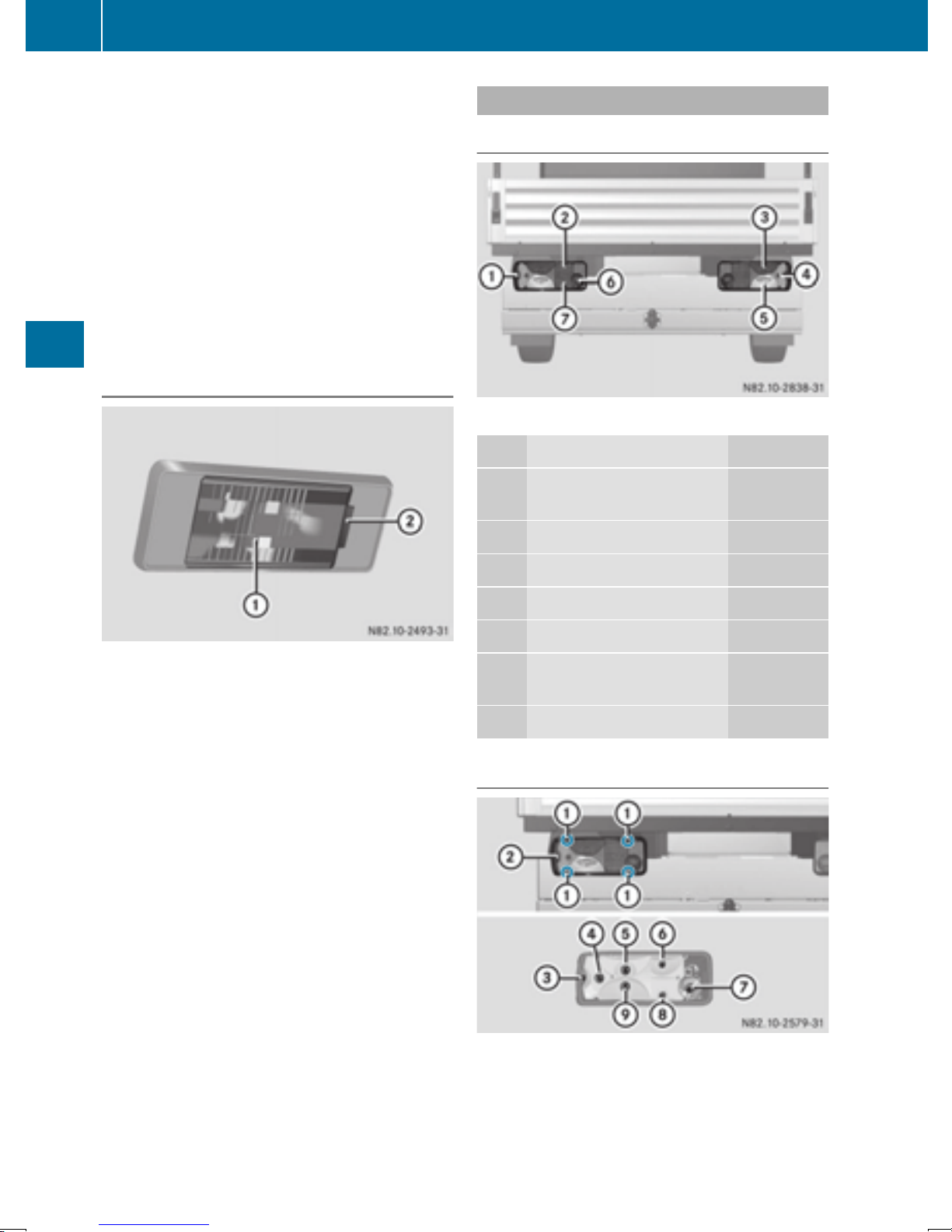
90
Changing bulbs
X
Release retaining lugs ; and take the bulb
holder out of the tail lamp.
X
Applying light pressure to the bulb, turn it
counter-clockwise and remove it from the
bulb holder.
X
Press the new bulb into the bulb holder and
screw it in clockwise.
X
Press the connector into the bulb holder.
X
Insert the lamp lens.
To do this, clip the bulb holder into the three
holes provided at the side and tighten
screws :.
License plate lamp
Rear bulbs (Cab Chassis)
Overview of bulb types
Chassis (example: Cab Chassis)
Lights Bulb type
X
Switch off the lighting system.
X
Insert a screwdriver or similar implement into
recess ; and carefully pry off lamp lens :.
Lights and windshield wipers
X
Pull the bulb out of the bulb holder.
X
Insert a new bulb.
X
Align lamp lens : and clip it in so that it
engages.
:
Perimeter lamp/standing lamp
;
=
?
A
B
Tail lamps R 5 W
Brake lamps P 21 W
Turn signal lamps PY 21 W
Backup lamps P 21 W
Rear fog lamps (driver's
side)
C
License plate lamp R 5 W
Tail lamps
R 5 W
P 21 W
:
Screws
;
Lamp lens
=
Perimeter lamp/standing lamp
?
Turn signal lamps
A
Brake lamps
B
Tail lamps
Page 93
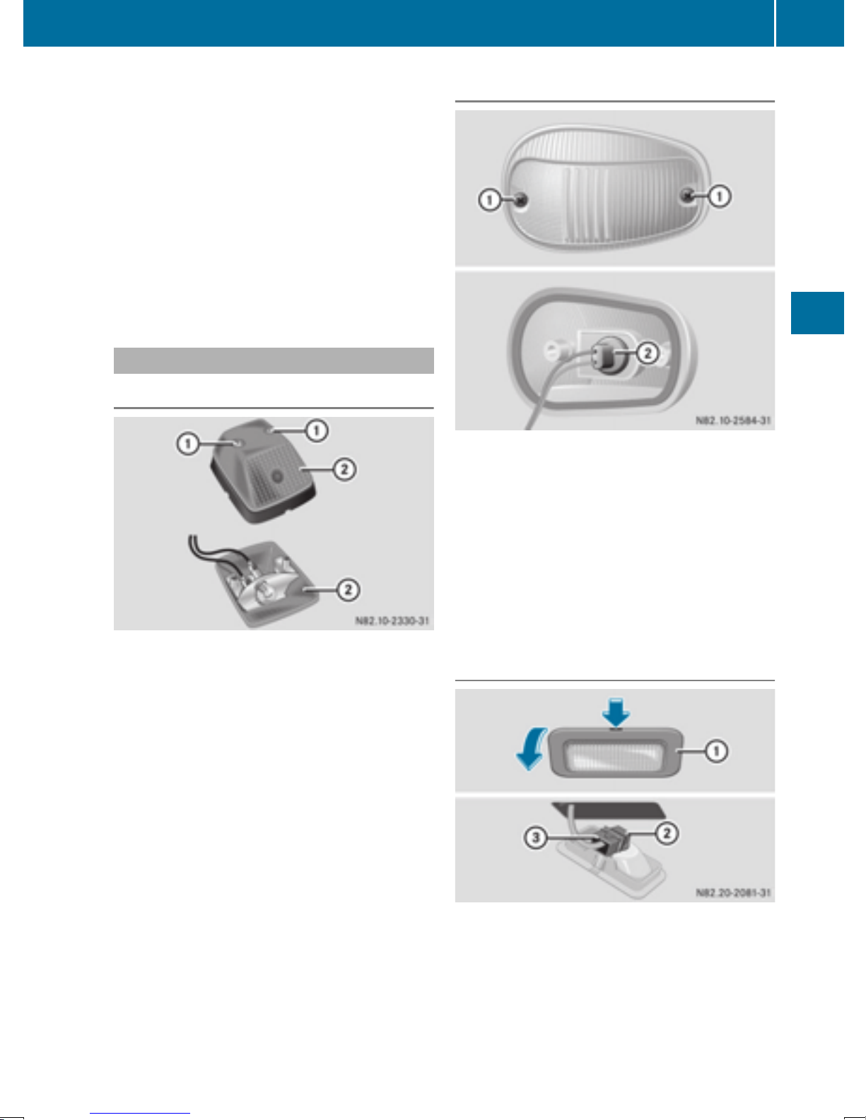
Changing bulbs
91
C
Rear fog lamp
D
License plate lamp
E
Backup lamps
X
Switch off the lighting system.
X
Undo screws : and remove lamp lens ;.
X
Applying light pressure to the bulb, turn it
counter-clockwise and remove it from the
bulb holder.
X
Press the new bulb into the bulb holder and
screw it in clockwise.
X
Position lamp lens ; and tighten screws :.
Additional lamps
Additional turn signal lamp on the roof
Perimeter lamp (Cab Chassis)
Type of lamp: W 5 W
X
Switch off the lighting system.
X
Undo screws : and remove the lamp unit.
X
Turn bulb holder ; and remove it.
X
Remove the bulb from bulb holder ;.
X
Press the new bulb into bulb holder ;.
X
Screw bulb holder ; into the lamp unit.
X
Carefully position the lamp housing and
tighten screws :.
Type of lamp: P 21 W
X
Switch off the lighting system.
X
Undo screws : and remove lamp lens ;.
X
Applying light pressure to the bulb, turn it
counter-clockwise and remove it from the
bulb holder.
X
Press the new bulb into the bulb holder and
screw it in clockwise.
X
Position lamp lens ; and tighten screws :
again.
Courtesy lights, rear compartment
Bulb type: W5W
X
Press in the latching spring of courtesy
light : with a suitable implement, e.g. a
screwdriver.
X
Pry off courtesy light :.
X
Disconnect cable connector =.
X
Unscrew bulb holder ;.
Lights and windshield wipers
Z
Page 94
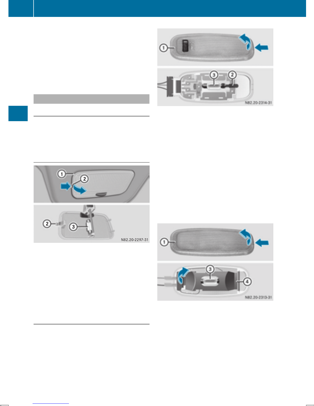
92
Changing bulbs
X
Remove the bulb from bulb holder ;.
X
Press the new bulb into bulb holder ;.
X
Screw bulb holder ; into courtesy light :.
X
Connect cable connector =.
The connector locking spring must engage.
X
Align courtesy light : on the side and
engage.
Interior lighting
General notes
Have the bulbs in the overhead control
!
panel replaced at a qualified specialist workshop. You could otherwise damage the overhead control panel.
Front interior light
Lights and windshield wipers
Type of lamp: K 18 W
X
Switch off the interior lighting.
X
Press spring catch ; in the direction of the
arrow and lift off interior light :.
X
Remove bulb = from the bulb holder.
X
Insert new bulb =.
X
Align interior light : on the right-hand side
and engage the spring catch.
Interior light with switch
Type of lamp: K 15 W
X
Switch off the interior lighting.
X
Press in the catch springs of lamp housing :
with a suitable object and pry off lamp housing :.
X
Press the contact spring of bulb holder ;
outwards and remove bulb =.
X
Insert a new bulb =.
X
Align lamp housing : on the left-hand side
and engage.
Vehicles with LED lighting: if an LED is
i
faulty, consult a qualified specialist workshop.
Interior light without switch
Interior light without switch
Rear interior light
Interior light with switch
Type of lamp: K 15 W
X
Switch off the interior lighting.
X
Press in the catch springs of lamp housing :
with a suitable object and pry off lamp housing :.
X
Open protective cover ?.
X
Press the contact spring of bulb holder ;
outwards and remove bulb =.
X
Insert new bulb =.
Page 95
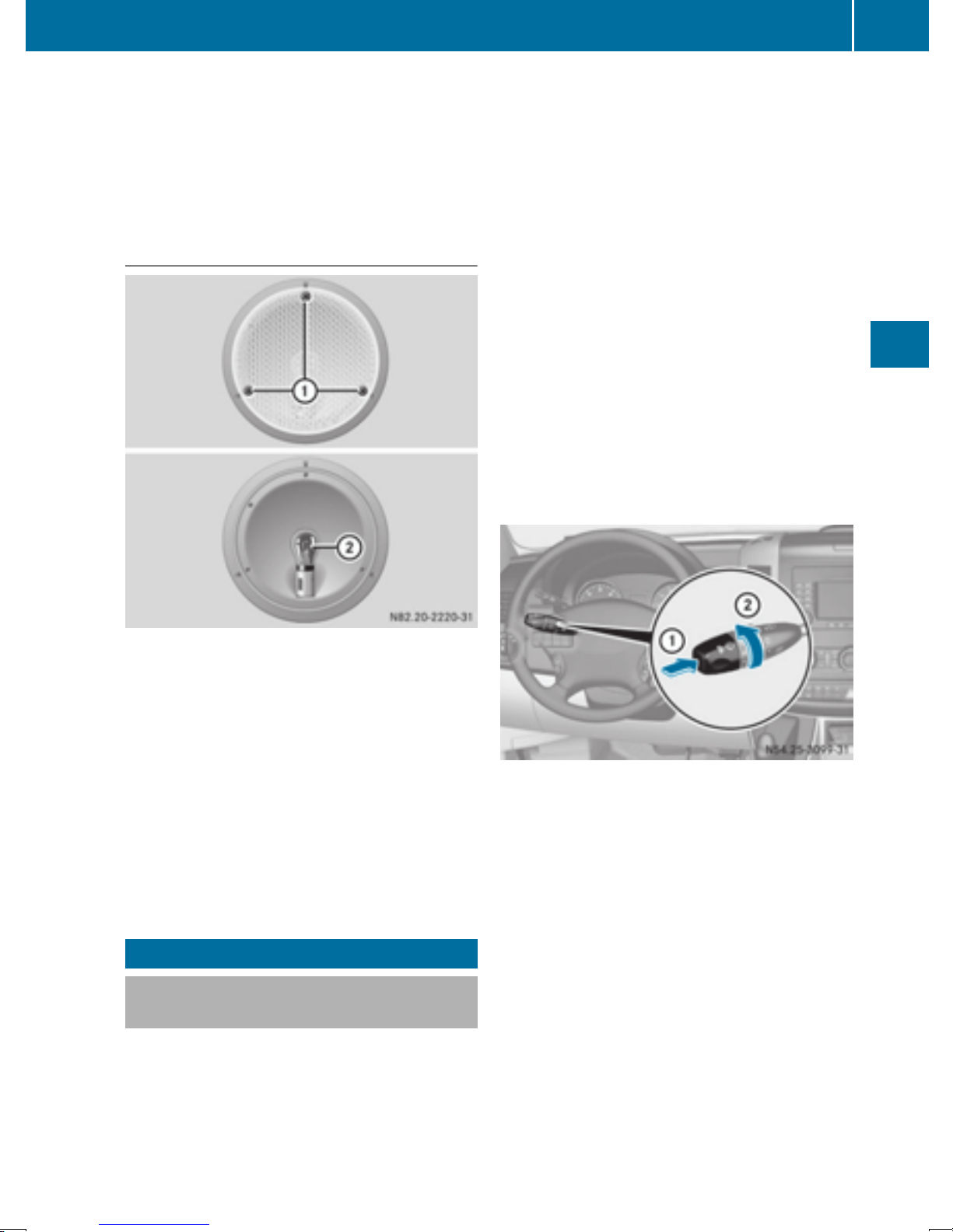
X
Fold protective cover ? back into place.
X
Align lamp housing : on the left-hand side
and engage.
Vehicles with LED lighting: if an LED is
i
faulty, consult a qualified specialist workshop.
Cargo compartment lamp
Windshield wipers
If it is necessary to switch on the windshield
wipers in dry weather conditions, always use
washer fluid when operating the windshield
wipers.
If the windshield wipers leave smears on the
!
windshield after the vehicle has been washed
in an automatic car wash, wax or other residues may be the reason for this. Clean the
windshield using washer fluid after washing
the vehicle in an automatic car wash.
Vehicles with rain/light sensor:
!
Switch the wipers off in dry weather. Otherwise, dirt or optical effects may cause undesired windshield wiper sweeps. This could
then damage the windshield wiper blades or
scratch the windshield.
The windshield will no longer be wiped properly
if the wiper blades are worn. Replace the wiper
blades twice a year (
spring and fall.
Y page 94), ideally in
93
Type of lamp: W 10 W
X
Switch off the interior lighting.
X
Undo screws : and remove the lamp lens.
X
Press bulb ; into the bulb holder and
unscrew it counter-clockwise.
X
Press new bulb ; into the bulb holder and
screw it in clockwise.
X
Position the lamp lens and tighten screws :.
Vehicles with LED cargo compartment
i
lamp: if an LED is defective, consult a qualified specialist workshop.
Windshield wipers
Switching the windshield wiper
on/off
Do not operate the windshield wipers when
!
the windshield is dry, as this could damage
the wiper blades. Moreover, dust that has collected on the windshield can scratch the glass
if wiping takes place when the windshield is
dry.
Combination switch
X
Turn the key to position 1 or 2 in the ignition
lock.
X
Turn the combination switch in the direction
of arrow ; to the appropriate setting
depending on the intensity of the rain.
X
Single wipe: push the combination switch
briefly to the pressure point in the direction of
arrow :.
X
To wipe with washer fluid: press the combination switch beyond the pressure point in
the direction of arrow :.
The detent positions of the combination switch
correspond to the following wiper speeds:
0Windshield wipers off
IIntermittent wipe
II Normal wipe
III Rapid wipe
Lights and windshield wipers
Z
Page 96
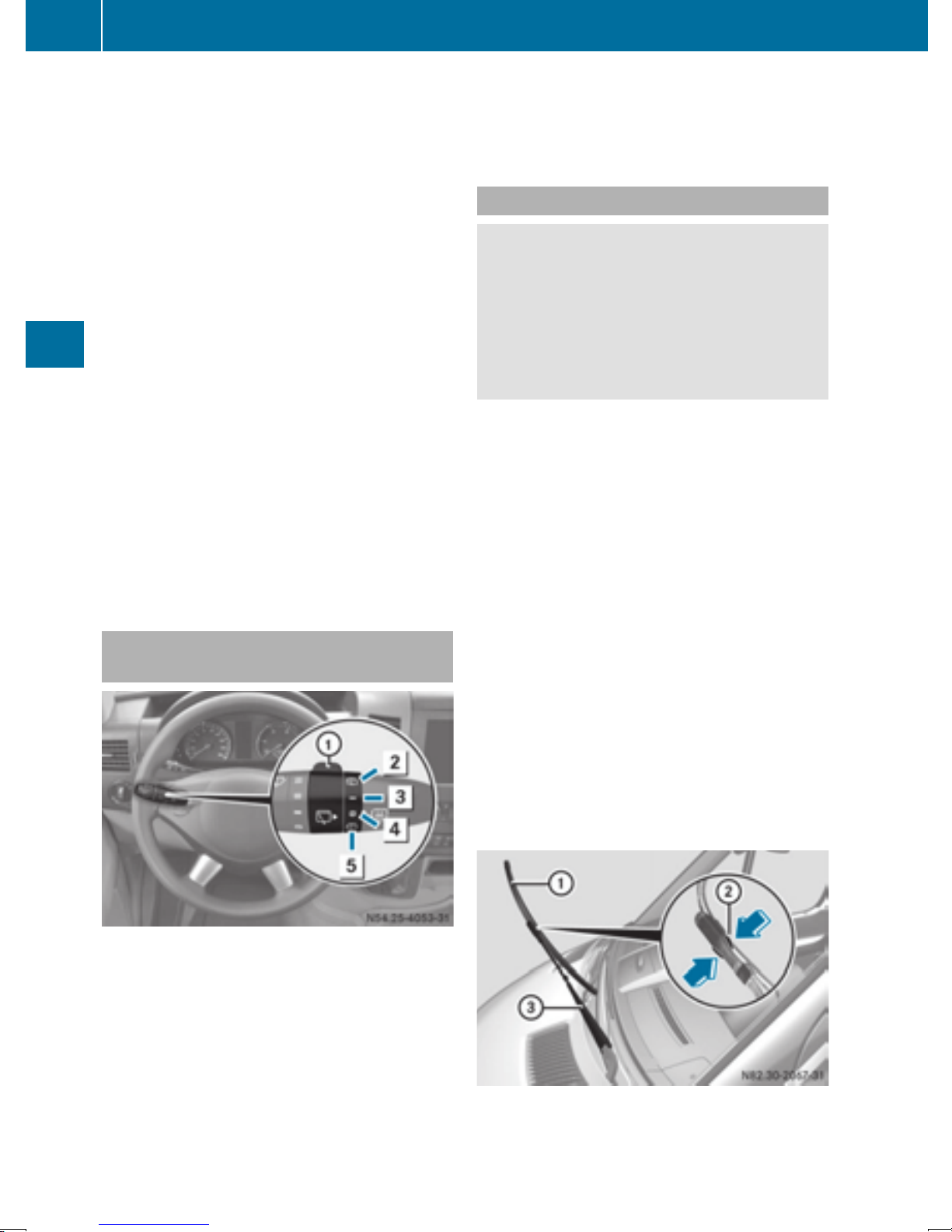
94
Windshield wipers
Canada only:
i
If the windshield wipers are switched on and
you stop the vehicle, the windshield wiper
speed is reduced. For example, if you have
selected level II and stop the vehicle, wiping
continues with intermittent wipe while the
vehicle is stationary. If intermittent wipe is
selected, the intervals become longer.
Vehicles with a rain and light sensor: you
can use level I as the universal setting. The
rain and light sensor sets the appropriate wiping frequency automatically, according to the
intensity of the rain. When you stop the vehicle, levels III and II are switched down to
level I automatically.
The windshield wiper will return to the original
level when you drive faster than 5 mph
(8 km/h).
You can adjust the sensitivity of the rain and
light sensor using the on-board computer
Y page 173).
(
Information on checking the washer fluid level
can be found in the "Maintenance and care"
section (
Y page 224).
Switching the rear window wiper on/
off
Lights and windshield wipers
The rear window wiper switches on automatically if you engage reverse gear and the windshield wipers are on.
Replacing the wiper blades
WARNING
G
If the windshield wipers begin to move while
you are changing the wiper blades, you could
be trapped by the wiper arm. There is a risk of
injury.
Always switch off the windshield wipers and
ignition before changing the wiper blades.
Never open the hood if a windshield wiper
!
arm has been folded away from the windshield.
Never fold a windshield wiper arm without a
wiper blade back onto the windshield/rear
window.
Hold the windshield wiper arm firmly when
you change the wiper blade. If you release the
windshield wiper arm without a wiper blade
and it falls onto the windshield, the windshield
may be damaged by the force of the impact.
We recommend that you have the wiper
blades replaced at a qualified specialist workshop.
Only hold the wiper blade by the wiper arm.
!
You could otherwise damage the wiper rubber.
Combination switch
:
è Rear window wiper switch
2
ô To wipe with washer fluid
3
I To switch on intermittent wiping
4
0 To switch off intermittent wiping
5
ô To wipe with washer fluid
X
Turn the key to position 1 or 2 in the ignition
lock.
X
Turn switch : to the corresponding position
The windshield will no longer be wiped properly
if the wiper blades are worn. Replace the wiper
blades twice a year, ideally in spring and fall.
Front windshield wiper arm with wiper blade
Page 97

X
Fold wiper arm = away from the windshield.
X
Set wiper blade : at right angles to the wiper
arm.
X
Press both retaining clips ; together in the
direction of the arrow and swing wiper
blade : away from wiper arm =.
X
Pull wiper blade : up and out of the retainer
on wiper arm =.
X
Slide new wiper blade : into the retainer on
wiper arm =.
X
Press new wiper blade : onto wiper arm =
until you hear retaining clips ; engage.
X
Fold wiper arm = back onto the windshield
again.
Windshield wipers
95
Lights and windshield wipers
Z
Page 98

96
Windshield wipers
Problems with the windshield wipers
Problem
The windshield wiper
jams.
The windshield wiper
does not move at all.
The windshield washer
fluid from the spray nozzles no longer hits the
center of the windshield/rear window.
Possible causes/consequences and M Solutions
Leaves or snow, for example, may be obstructing the windshield wiper
movement. The wiper motor has switched off.
X
Stop the vehicle as soon as possible, paying attention to road and
traffic conditions.
X
For safety reasons, you should remove the key from the ignition
lock.
X
Remove the cause of the obstruction.
X
Switch on the windshield wipers again.
There is a malfunction in the windshield wiper drive.
X
Select another wiper speed on the combination switch.
X
Have the windshield wipers checked at a qualified specialist workshop.
The spray nozzles are misaligned.
X
Have the spray nozzles checked at a qualified specialist workshop.
Lights and windshield wipers
Page 99

Overview of climate control systems
Useful information
This Operator's Manual describes all models as
well as standard and optional equipment of your
vehicle that were available at the time of going
to print. Country-specific variations are possible. Note that your vehicle may not be equipped
with all of the described functions. This also
applies to systems and functions relevant to
safety.
Read the information on qualified specialist
workshops (
Overview of climate control systems
Important safety notes
Observe the recommended settings on the following pages. Otherwise, the windows could fog
up.
Climate control regulates the temperature and
the humidity in the vehicle interior and filters
undesirable substances from the air.
Climate control is only operational when the
engine is running. The system only functions
optimally when the side windows are closed.
Y page 26).
97
Climate control
Ventilate the vehicle for a brief period during
i
warm weather. In order to cool the vehicle
more rapidly, switch climate control to airrecirculation mode briefly. This will speed up
the cooling process and the desired interior
temperature will be reached more quickly.
The integrated filter can filter out most par-
i
ticles of dust and completely filters out pollen.
A clogged filter reduces the airflow into the
vehicle interior. For this reason, you should
always observe the interval for replacing the
filter, which is specified in the Maintenance
Booklet. As it depends on environmental conditions, e.g. heavy air pollution, the interval
may be shorter than that stated in the Maintenance Booklet.
Page 100
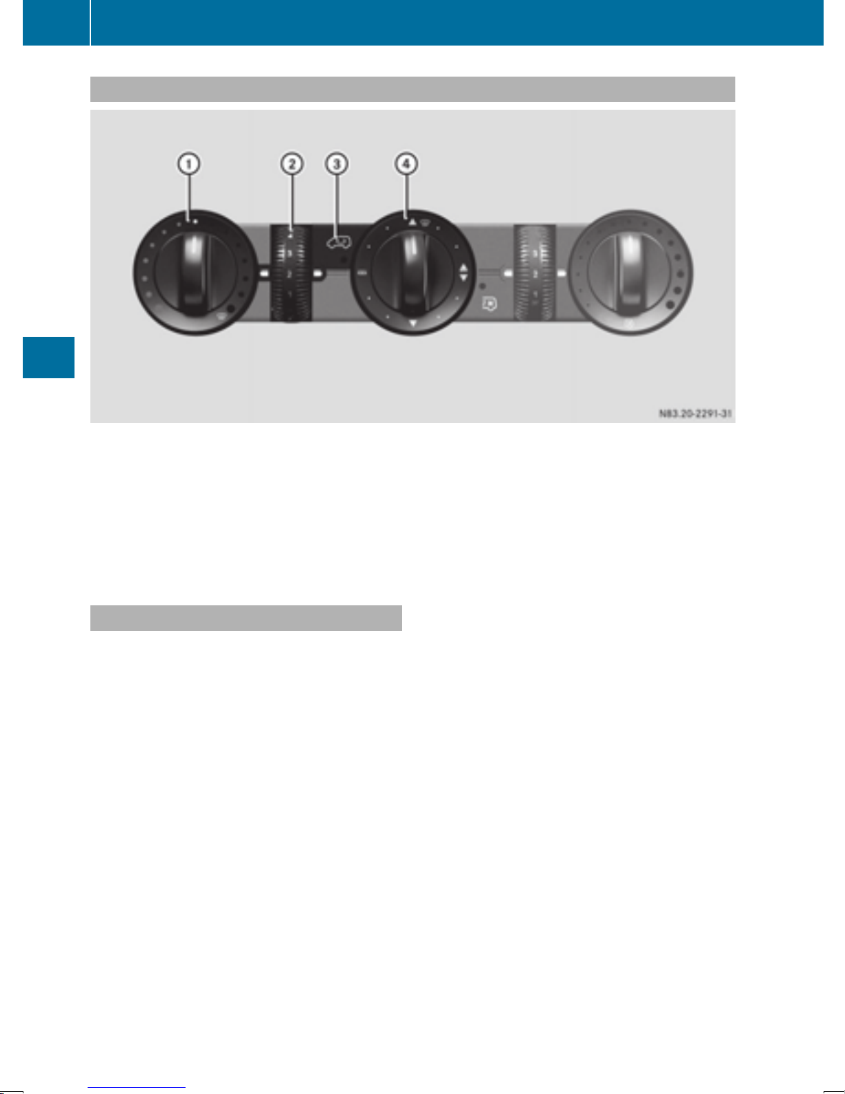
98
Overview of climate control systems
Heating control panel
:
Sets the temperature (Y page 102)
z Defrosts the windshield (
;
K Sets the airflow (Y page 102)
z Defrosts the windshield (
=
e Activates and deactivates air-recirculation mode (Y page 104)
?
Climate control
Sets the air distribution (Y page 102)
Y page 103)
Y page 103)
sz Defrosts the windshield (
Information on heating
Below, you can find a number of notes and recommendations to help you use the heating optimally.
R
Set the temperature control to the middle
level. Only change the temperature in small
increments.
If you wish to heat up the vehicle interior as
quickly as possible, set the temperature control to the z maximum setting. When the
desired interior temperature has been
reached, turn the temperature control back
down in small steps.
R
Only use the settings for defrosting the windshield briefly, until the windshield is clear
again.
R
Only use air-recirculation mode briefly, e.g. if
there are unpleasant outside odors or when in
a tunnel. The windows could otherwise fog up
as no fresh air is drawn into the vehicle in airrecirculation mode. The indicator lamp in the
h button comes on when the function is
switched on.
Y page 103)
 Loading...