


I. Introduction
Merax Pipe Benders are designed to bend Schedule 40 pipes with diameters of
½” to 3” and ½” to 4”, in accordance with Standards DIN2441. They are versatile
and easy to use and are sold in two versions: Pneumatic - Hydraulic Pipe
Bender and Electric-Hydraulic Pipe Bender.
Pipe Benders in two versions.
1

Before using your Merax Pipe Bender, check:
1) Electric-Hydraulic Model (220V): Oil level in tank must be filled (Hydraul i c
system oil 68; not included).
2) Pneumatic - Hydraulic Model: Oil already stored in machine. Check only
compressed air pressur e. (KG/PSI) 8/120.
Oil tank
(Electric-Hydraulic)
Use a
funnel to fill tank
with oil.
Use only Hydraulic System Lubricant 68.
3) The amount and level of oil (± 8 liters) can be monitored by the level opposite
the manometer. The level must be full when equipment is off and the bender
cylinder ram retracted.
2

II. Installation
Installing the Pipe Bender;
1) Tighten the cylinder ram to the lower plate using the screws supplied with machine.
(Fig. 2).
Fig. 1 Fig. 2
Area for installation
of cylinder ram
Lower
plate.
Cylinder ram
installed on
lower plate.
2) Tighten upper plate (Fig. 3) on top of the cylinder ram. (Fig. 4).
Upper plate
Fig. 3 Fig. 4
Plates attached
to cylinder ram.
3

3) Pneumatic-Hydraulic model: Install compressed air hose into the
trigger of the pneumatic motor (Fig. 7).
4) Electric-Hydraulic Model: Install compressed air hose into electric-hydraulic
pump (Fig. 6), and then, on hydraulic cylinder ram (Fig. 5).
Fig. 5 Fig. 6
Hoses.
Hoses
attached to
piston.
Electric-
Hydraul
ic Pump
Fig. 7
Compressed air fitting.
5) Fit degrees plate, according to pipe size. Then fit swaging blocks, checking
the markings on the top of the bender. (Fig. 8). (Fig. 9).
Fig. 8 Fig. 9
3-face swaging
blocks to be used
according to pipe
diameter.
4
4
6) Define the position of the swaging blocks and place them on the same
position. Them install the pipe between the swaging blocks and lower the
upper plate. (Fig. 10). (Fig. 11)
Pipe
installed.
Fig. 10 Fig. 11
Upper plate lowered.
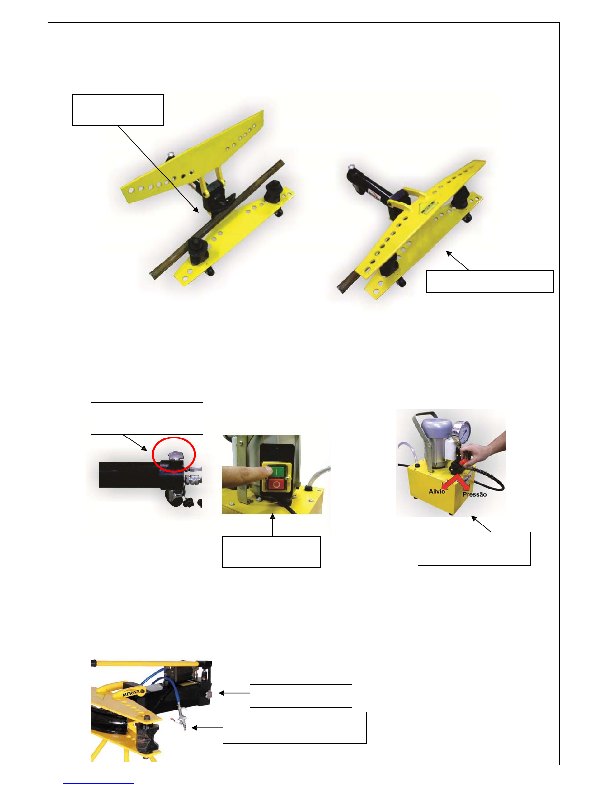
7) Electric-Hydraulic Model: Close the piston relief valve (Fig. 12), turn motor on
(Fig. 13). Turn valve to “pressure”, making hydraulic cylinder move towards the
pipe. (Fig. 14). To stop cylinder motion, turn valve back to initial position and open
relief valve.
Fig. 12 Fig. 13 Fig. 14
Piston relief valve.
Motor On/Off
switch
Pressure Valve
control switch.
8) Pneumatic-Hydraulic model: Loosen the nut beside the pneumatic motor,
close relief valve and pull the pneum ati c motor trigger (Fig. 15), making cylinder
ram move forward; to move back use relief valve.
Fig. 15
Relief valve
Pneumatic drive trigger
5

Merax Pipe Benders DO NOT bend very sharp angles in a single
process.
WARRANTY
MERAX Pipe Bend ing Machines are guarantee d for 6 months in Brazil from the date of issue of
invoice or delivery of the product to the final consumer.
This warranty applies to manufacturing, materials, parts and workmanship defects, when
adequately proven.
This warranty does not ap pl y to dam ages pro voked b y inadequate transportati on, ac cidents of an y
type, misuse, electrical installation oscillations, use of wro ng voltage, bad quality of compres sed
air, the removal or alteration of the series number of the machine, and the non-compliance with the
instructions herein contained. This warranty does not apply to any component that deteriorates
under normal use.
Check parts listing and their codes in our website: www.merax.com.br
6

 Loading...