

Page 1

Copyright © 2010, Meraki, Inc.
1 of 9
Meraki Implementation Note:
Extending a LAN wirelessly between
sites using the Meraki MR58
Version 1.0, June 2010
In a multi-site deployment, wired infrastructure may not be available
between sites, but LAN connectivity for both sites is still required. In
this case, a wireless point-to-point link may be beneficial to connect the
two sites together.
Page 2

Copyright
© 2010 Meraki, Inc. All rights reserved.
Trademarks
Meraki® is a registered trademark of Meraki, Inc.
www.meraki.com
660 Alabama St.
San Francisco, California 94110
Phone: +1 415 632 5800
Fax: +1 415 632 5899
2 of 9
Page 3

Wireless LAN Extension
Table of Contents
1 The Benefits of a Wireless Bridge ...................................................................................................... 4
2 Using the Meraki MR58 for your Point-to-Point Link ........................................................................ 5
2.1 Setting up the MR58 for Point-to-Point Connectivity ........................................................................ 5
2.2 Adding Wired Connectivity to the Remote Site ................................................................................. 5
2.3 Adding Meraki AP’s to the remote side of the link ............................................................................ 6
2.4 VLANs ................................................................................................................................................. 7
3 Configuring your Point-to-Point link in the Dashboard ...................................................................... 8
4 Conclusion ........................................................................................................................................ 9
3 of 9
Page 4

Wireless LAN Extension
1 The Benefits of a Wireless Bridge
Wireless bridges can be used to connect geographically distant sites
together without the expense of installing wired networking cable. A
bridge enables one or more remote sites to appear to be on the same
network as a central site, ensuring access to resources such as file
shares, Domain services, and so on. Meraki bridges are simple to
install, configure, and maintain.
4 of 9
Page 5

Wireless LAN Extension
2 Using the Meraki MR58 for your Point-to-Point Link
This chapter summarizes the equipment requirements for setting up a
wireless link and how the Meraki MR58 would be configured for this
deployment scenario.
2.1 Setting up the MR58 for Point-to-Point Connectivity
While all MR-series Meraki AP’s have the capability to extend a LAN
wirelessly between buildings, the MR58 is the best choice for this type of
deployment. The MR58 is a triple-radio device, with two radios in the
5GHz band and one configured for the 2.4GHz band. In most cases,
wireless point-to-point equipment will be mounted outdoors and will
require external antennas which can be aimed for optimal connectivity.
The Meraki MR58 meets both of these requirements, as well as having
full mesh capability and offering client connectivity.
The most common configuration of the unit in a point-to-point scenario is
to attach a panel antenna to one of the 5GHz radios on each unit, and
point these antennas at each other. This is the connection that will span
the distance between the two buildings. The second and third radios
have omni-directional antennas attached to them in order to offer
wireless client connectivity at both sides of the link.
2.2 Adding Wired Connectivity to the Remote Site
The manner in which a point-to-point link will link sites is to have one unit
serve as the Meraki gateway (at the home site) and one unit function as
a repeater (at the remote site).
It is important that the Meraki unit at the remote site act as a repeater.
The way Meraki determines whether a device should be a repeater or a
gateway is that, at boot time, the unit sends out a DHCP request.. If it
receives a DHCP reply from any device on the wired network, it assumes
this is a valid LAN connection and it should use this connection to
become a Meraki Gateway. This means that in order for the point-topoint link to establish correctly, no network elements on the remote site
should respond to DHCP requests. Note it is not possible to configure a
static IP address for the repeater at the remote site because doing so will
automatically designate the device as a gateway instead of a repeater.
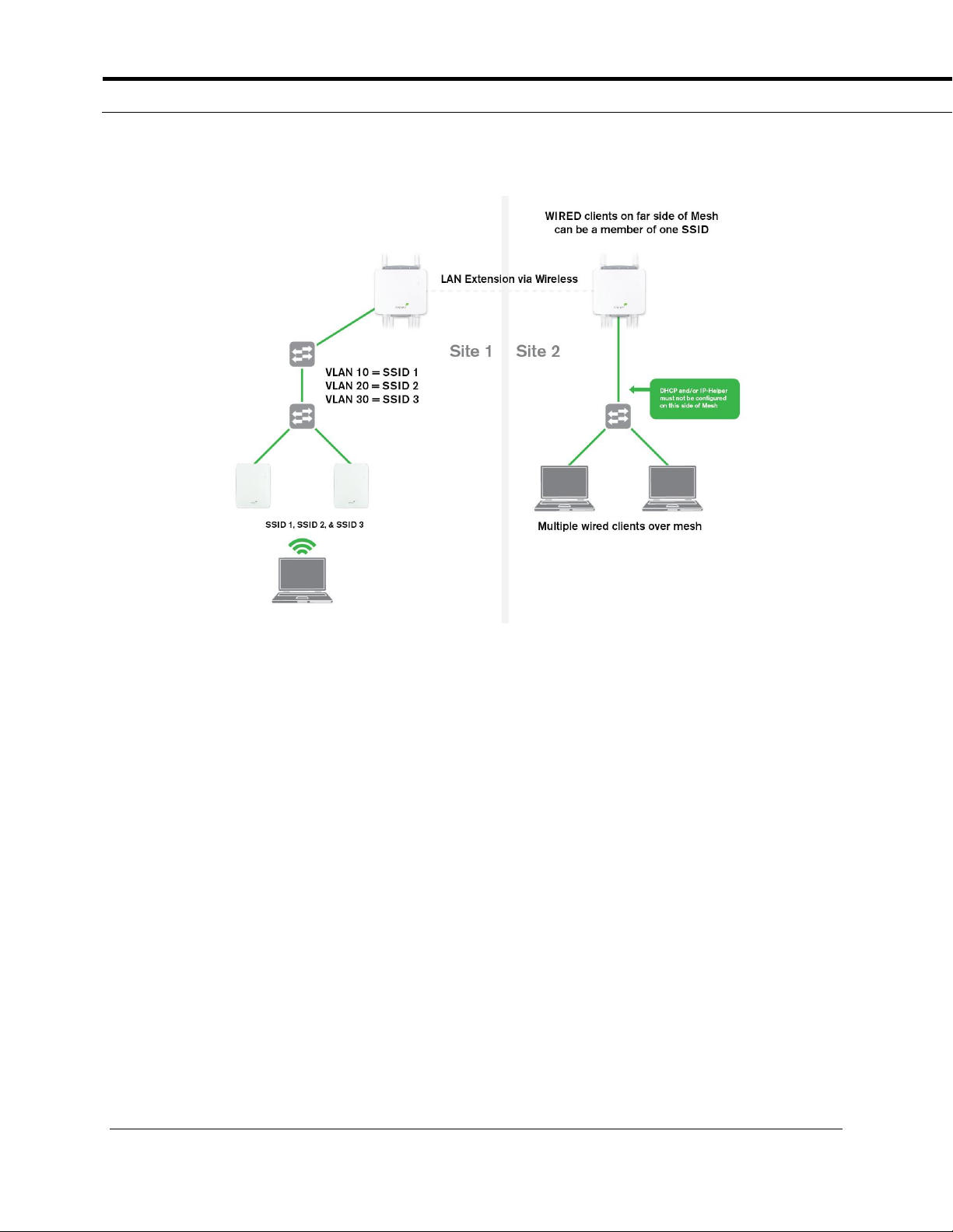
Once the Meraki Gateway is established, the repeater on the remote
side can be configured to accept wired clients on its Ethernet interfaces.
At the remote site, a switch can be plugged into the available Ethernet
port(s) on the MR58 to provide wired client connectivity to more than one
wired client, creating a small office LAN. Note the picture below.
5 of 9
Page 6
Wireless LAN Extension
2.3 Adding Meraki AP’s to the remote side of the link
Depending on the size of the area that requires coverage, you may
require more than one AP on the remote side of the link. The MR58 has
two Ethernet interfaces for wired connectivity, both of which can accept
either wired client traffic or wired Meraki traffic. Wired Meraki traffic
would be generated any time a “wired hop” is created, i.e. when a Meraki
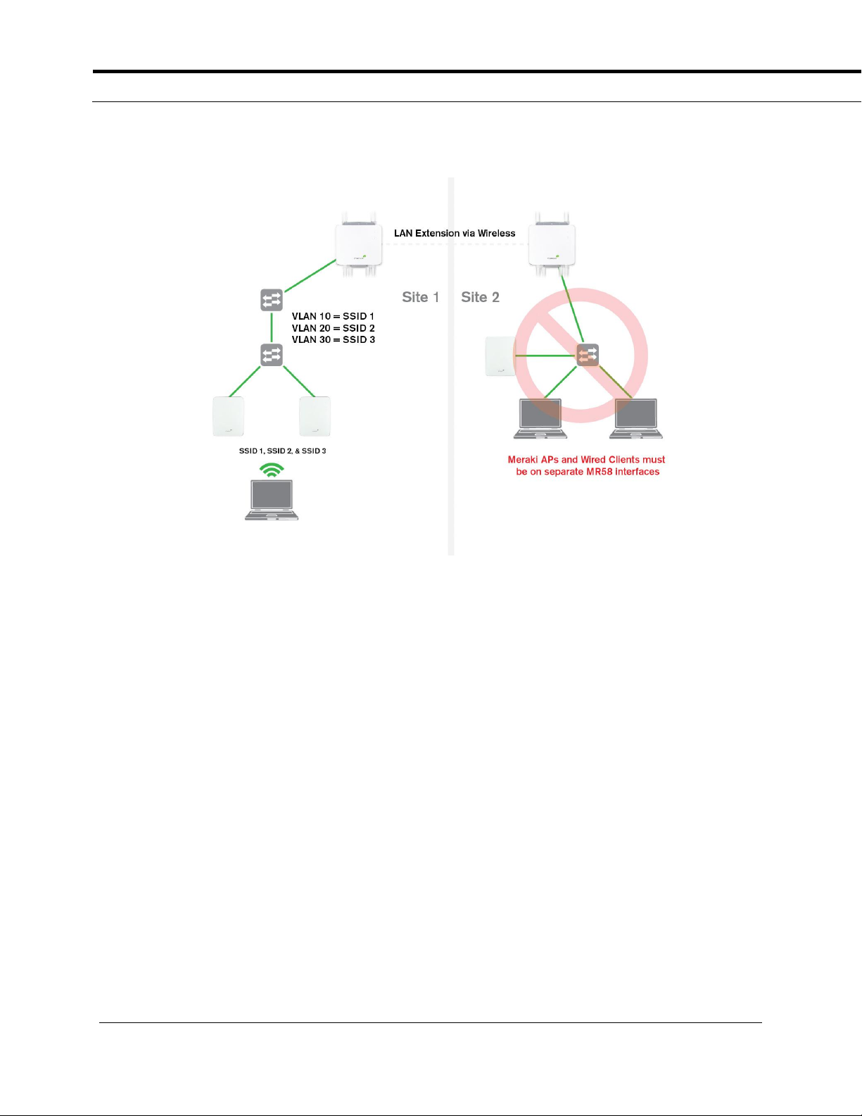
AP is plugged into a neighboring Meraki AP for connectivity. So to
properly connect multiple Meraki devices to the MR58 repeater’s wired
interface, a switch must be added that has ONLY Meraki equipment
connected to it. A mixture of wired clients and wired Meraki AP’s
attached to one MR58 interface will not work. This is due to the auto-
detection mechanisms that Meraki AP’s use to understand if they should
function as a gateway or a repeater. The second wired interface can be
leveraged for wired client connectivity if appropriate. Note the picture
below.
6 of 9
Page 7
Wireless LAN Extension
2.4 VLANs
While VLAN configuration remains unaffected at the central site in all
cases, the remote site’s WIRED connectivity must be a member of one
VLAN only (wireless clients will be unaffected). Any VLAN that has been
configured for an SSID in the Meraki network can be selected as the
remote site VLAN.
7 of 9
Page 8

Wireless LAN Extension
3 Configuring your Point-to-Point link in the Dashboard
The two MR58 units forming the point-to-point link must be in the same
logical network as the rest of your Meraki equipment. In addition, there
are two configuration settings in the Meraki Dashboard that must be
applied in order for the wireless link to function properly:
1) Under Configure -> Access control –> Addressing and Traffic, the
Bridge Mode radio button should be selected. This will instruct the
Meraki network to operate as a wireless extension of your LAN and
rely on the LAN configuration for all network connectivity
2) Under Configure -> Network-wide settings -> Device Configuration
select Clients wired directly to Meraki AP’s behave like they are
connected to [SSID name]. This ensures that your point-to-point
traffic inherits the settings for the appropriate SSID.
8 of 9
Page 9

Wireless LAN Extension
4 Conclusion
The MR58 is an easily deployable solution to link two sites together
using a wireless point-to-point bridge. There is no complicated setup
such as you might expect with traditional wireless bridging products
since the Meraki Mesh automates link creation. Connecting all areas of
a campus together on one network simplifies management, leverages
existing internal resources, and enables single sign-on for wireless users
across the campus.
9 of 9
 Loading...