

MEP FSK700, FSK700-2, FSK700-2SX User Manual

Fire Brigade Key Safe
FSK700-2 / FSK700-2SX
User Manual
Description
Installation - Connection – Commissioning - Maintenance
VdS Approval: G 199055
© by MEP-Gefahrenmeldetechnik GmbH


User Manual FSK700-2 / FSK700-2SX 3
Contents
1 Introduction................................................................................................................................... 5
1.1 General............................................................................................................................................5
1.2 Description of the Series FSK700 Key Safe...................................................................................5
1.2.1 Main features of the Series FSK700 Key Safe............................................................................. 6
1.3 Types of signs................................................................................................................................. 7
1.4 Outline of the manual......................................................................................................................7
1.5 Abbreviations..................................................................................................................................7
1.6 Important advice for the operator and specialist installer................................................................7
1.7 Cleaning the Series FSK700 Fire Brigade Key Safe.......................................................................8
1.8 Product contents.............................................................................................................................. 8
1.9 Product overview............................................................................................................................ 9
1.10 Special terms................................................................................................................................. 10
1.11 Standards, Guidelines, CE marking..............................................................................................11
1.12 Warranty.......................................................................................................................................11
2 Function........................................................................................................................................ 12
2.1 Normal condition.......................................................................................................................... 12
2.2 Fire alarm condition......................................................................................................................12
2.3 Activation of the unblocking device.............................................................................................13
2.4 Fire alarm reset............................................................................................................................. 13
2.5 Sabotage alarm.............................................................................................................................. 13
3
3 Installation....................................................................................................................................14
3.1 General..........................................................................................................................................14
3.2 Installation site.............................................................................................................................. 14
3.3 Installation of Flush Mounting Frame EZ700-2 or Flush Mounting Frame with
Drill Protection EZBS700-2..........................................................................................................15
3.4 Installation of Flush Mounting Frame EZ700-2 or Flush Mounting Frame with
Drill Protection EZBS700-2 in Key Safe Column SDS700-2.......................................................15
3.5 Preparation of the Fire Brigade Key Safe......................................................................................15
3.5.1 Removal of the inner door angle................................................................................................16
3.5.2 Installation of a locking half cylinder in the Locking Cylinder Mounting Bracket.....................16
3.5.3 Installation of additional locking half cylinders in Key Safe FSK700-2SX................................17
3.5.4 Installation of the inner door......................................................................................................18
3.6 Installation of the Fire Brigade Key Safe in the Flush Mounting Frame.......................................19
4 Connection.................................................................................................................................... 20
4.1 Preparation of the connection cables.............................................................................................20
4.2 Inner view of the Fire Brigade Key Safe.......................................................................................21
4.3 Layout of Connection Board APL-4.............................................................................................21
4.4 Connecting....................................................................................................................................22
4.4.1 Complete connection diagram.................................................................................................... 22
4.4.2 Connecting the Flush Mounting Frame with Drill Protection, or the Tamper Switch
of the Key Safe Column............................................................................................................. 24
4.4.3 Heating device of the Series FSK700 Fire Brigade Key Safe.....................................................24
4.5 Connecting the cables of the Key Safe to Connection Board APL-4............................................24
4.5.1 Ribbon cable of the outer door...................................................................................................25
4.5.2 Cable of the closure device.........................................................................................................25
4.5.3 Connecting the cables of the Locking Cylinder Mounting Brackets...........................................25
4.6 Typical connection diagram of a fire detection control panel and the Fire Brigade Key Safe.......26
4.6.1 Connection diagram of a system comprising fire detection control panel,
Series FSK700 Key Safe, Key Safe Controlling and Monitoring Device AD900-1,
and Power Supply Unit NT700-1...............................................................................................26
4.6.2 Connection diagram of a system comprising fire detection control panel,
HB_FSK700_1020_9161690_Englisch_D.odt / 1022 D
ZN62163/38/3

4 User Manual FSK700-2 / FSK700-2SX
4
burglar alarm control panel, and Fire Brigade Key Safe.............................................................26
4.6.3 Connection diagram of a system comprising burglar alarm control panel and
Fire Brigade Key Safe, without fire detection control panel.......................................................27
5 Commissioning............................................................................................................................28
5.1 General..........................................................................................................................................28
5.2 Notes on insurance protection....................................................................................................... 28
5.3 Configuration with jumpers..........................................................................................................28
5.3.1 Activation temperature of the outer door heating device............................................................28
5.3.2 Acoustic warning signal when missing master key....................................................................28
5.3.3 Automatic deactivation of the release magnet when outer door is open.....................................29
5.4 Commissioning instructions..........................................................................................................29
6 Inspection, maintenance, service............................................................................................. 32
6.1 Inspection, maintenance................................................................................................................ 32
6.2 Advice on fault correction of electrical parts................................................................................33
7 Technical specifications.............................................................................................................35
7.1 Fire Brigade Key Safe FSK700-2, FSK700-2SX..........................................................................35
7.2 Inner doors.................................................................................................................................... 35
7.2.1 Inner Door for FSK700-2/2SX/PHZ/30.5mm ITA-2..................................................................35
7.2.2 Inner Door for FSK700-2/2SX/PHZ/35.5mm ITA-3..................................................................35
7.2.3 Inner Door for FSK700-2/2SX/DBUS ITB-2.............................................................................36
7.2.4 Inner Door for FSK700-2/2SX/DBUS ITF-2.............................................................................36
7.3 Flush Mounting Frames................................................................................................................36
7.3.1 Flush Mounting Frame EZ700-2................................................................................................36
7.3.2 Flush Mounting Frame with Drill Protection EZBS700-2..........................................................36
7.4 Locking Cylinder Mounting Bracket for FSK700-2SX PHZAW700-2S1....................................36
7.5 Auxiliary Locking Cylinder for FSK700-2/2SX PHZ700-2..........................................................36
7.6 Weather Protection Hood for FSK700-2/2SX WSD-FSK.............................................................36
8 Certifications................................................................................................................................37
8.1 VdS Certificate.............................................................................................................................37
8.2 EC Declaration of Conformity......................................................................................................38
Safety Instructions
Prior to installing, operating, or providing maintenance to the products described herein,
the respective chapters of this manual must strictly be read, and especially the safety
information on page 7 and onwards in chapter 1.6 "Important advice for the operator and
specialist installer" must be implicitly observed and followed.
Furthermore, the pictographs on page 7 in chapter 1.3: "Types of signs" are highly
important – the many passages in this manual marked by these pictographs contain warnings of dangers that can arise from inappropriate usage of the product, as well as other
valuable advice.
Described in this manual is the range of functions of the Fire Brigade Key Safes FSK700-2
and FSK700-2SX (combinedly termed "Series FSK700") with Connection Board APL-4
(version number PN60046V2-H005) and Door Protection Board BOHR-4 (version number PN60047V1-H002). Outer dimensions are applicable from production number
08/06806 onwards. The functionality of units with a different production number can differ from the description in this manual in some points.
HB_FSK700_1020_9161690_Englisch_D.odt / 1022 D / AN9161690
ZN62163/38/4
User Manual FSK700-2 / FSK700-2SX Chapter 1 • Introduction 5
1 Introduction
1.1 General
Fire Brigade Key Safes serve for the theft-proof, copy-protected safekeeping of master keys, allowing the Fire Brigade to enter a building swiftly and without use of force in the event of fire.
The Fire Brigade Key Safe is installed in the entry area of the respective site. Upon alarm activation of the fire detection system, the outer door is unlocked remotely by the fire brigade, granting
access to the inner door of the Key Safe.
1.2 Description of the Series FSK700 Key Safe
Fire Brigade Key Safes FSK700-2 and FSK700-2SX (combinedly termed "Series FSK700"), as
manufactured by MEP-Gefahrenmeldetechnik GmbH (abbreviated "MEP" hereafter), are distinguished by application of solid, high-quality materials, as well as intelligent details in design,
achieving high security against unauthorised taking of master keys. Furthermore, master keys can
be secured by integrating the electric surveillance devices of the Key Safe in a burglar alarm system.
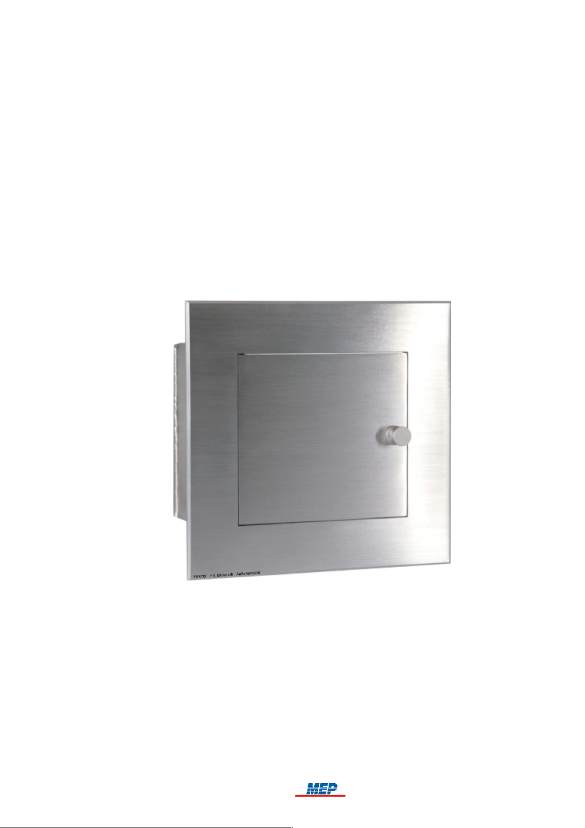
5
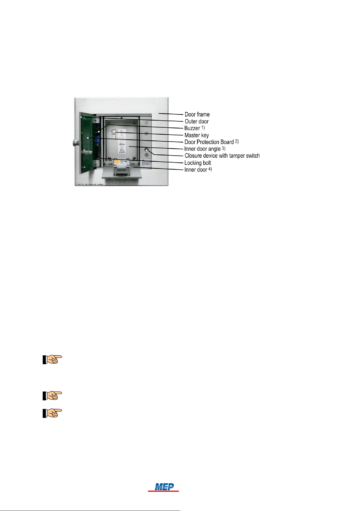
Fig. 1: Series FSK700 Fire Brigade Key Safe – front view
Series FSK700 consists of
Key Safe FSK700-2 (MEP Article No. 265740), in which one master key can be kept,
Key Safe FSK700-2SX (MEP Article No. 265742), of which the basic version can keep up to
two master keys, and can be upgraded with two Locking Cylinder Mounting Brackets to keep a
total of four master keys,
a range of accessory parts, described in chapter 1.9: "Product overview", from page 9 onwards.
HB_FSK700_1020_9161690_Englisch_D.odt / 1022 D / AN9161690
ZN62163/38/5
6 Chapter 1 • Introduction User Manual FSK700-2 / FSK700-2SX
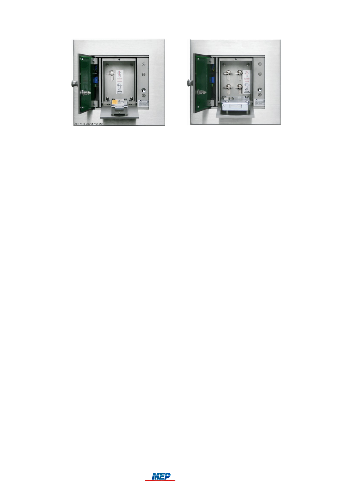
6
Fig. 2: Series FSK700 Fire Brigade Key Safe
On the left: FSK700-2 with open outer and inner doors, master key inserted, inner door fitted
with a double-bit variable lock
On the right: FSK700-2SX with 4 master keys, open outer and inner doors, inner door fitted with
a lock for a locking half cylinder
1.2.1 Main features of the Series FSK700 Key Safe
The Series FSK700 Key Safe has been tested and certified (Certification No. G 199055) by VdS
Schadenverhütung GmbH (VdS). In combination with a VdS-certified Key Safe controlling and
monitoring device, it can be employed together with most commercially available 12V or 24V fire
detection and burglar alarm systems.
The Series FSK700 Key Safe conforms to DIN 14675 Appendix C – Class 3 (FSD 3, high risk).
Up to four master keys can be stored inside a Fire Brigade Key Safe, thus meeting even complex
organisational requirements.
Due to intelligent details in design – for instance, protected outer door hinges – high security
against unauthorised opening is achieved.
The self-adjusting magnetic closure device automatically assumes the optimal position – therefore,
the closure device is able to function at the highest precision level, even during long-time opera-
tion under unfavourable temperatures or environmental conditions.
To guarantee high corrosion resistance and mechanical stability, all vital mechanical parts are
made from stainless steel.
Installation of the Key Safe is easy and smooth due to the Flush Mounting Frame introduced
many years ago in Germany by MEP.
An acoustic warning signal will sound from the Key Safe if not all master keys have been inserted
correctly.
For application of different locking mechanisms, such as double-bit variable locks or locking half
cylinders, suitable inner doors are available.
To assure unhindered opening of the Key Safe at low outside temperatures, the outer door can be
electrically heated with 12V or 24V AC or DC. Heating is controlled by temperature, operating
only at temperatures below +10°C (at factory default settings).
Adaption of the magnetic closure device and heating device to different voltages (12V or 24V) is
performed automatically by all Series FSK700 units, guaranteeing quick and problem-free commissioning.
HB_FSK700_1020_9161690_Englisch_D.odt / 1022 D / AN9161690
ZN62163/38/6

User Manual FSK700-2 / FSK700-2SX Chapter 1 • Introduction 7
1.3 Types of signs
Especially important passages in this manual are marked with signs. The following signs are used:
ATTENTION! Disregard of this reference can lead to malfunction or damage to the unit.
TIP! This passage contains notes that will help ease operation.
The country-specific and/or the site-specific requirements of the device and/or system
APPROVALS must be observed.
1.4 Outline of the manual
Following the safety instructions on page 4, and guidelines given in the first chapter, which
should be implicitly observed,
chapter two contains all information required to operate a Series FSK700 Fire Brigade Key
Safe. It is explained how the Fire Brigade Key Safe works in combination with a fire detection
control panel, a controlling and monitoring device, an unblocking device, and a transmitting
device, as well as describing in which situations sabotage alarm is activated.
7
In chapter three, relevant guidelines for the installation of the Fire Brigade Key Safe by a spe-
cialist installer are given.
In chapter four, the specialist installer is provided with an overview of the arrangement of ter-
minals, connectors, and other important elements, as well as information required to connect
the Fire Brigade Key Safe to an MEP Key Safe Controlling and Monitoring Device AD900-1,
and to a fire detection control panel.
In chapter five, commissioning of the Fire Brigade Key Safe is described in detail for the spe-
cialist installer.
In chapter six, notes on inspection and maintenance of the unit are given. Also described in
this chapter are possible causes of malfunction and steps to correct them.
In chapter seven, all essential technical specifications of the unit are presented.
In chapter eight, copies of the VdS-Prüfzertifikat and the EC Declaration of Conformity are
provided.
1.5 Abbreviations
The correct designations for both Key Safe types "Fire Brigade Key Safe FSK700-2" and "Fire Brigade Key Safe FSK700-2SX" are shortened to "Fire Brigade Key Safe", "Key Safe", or "Series
FSK700" for improved readability of the manual. Differences between the two types are noted in
the respective text passages.
1.6 Important advice for the operator and specialist installer
The keeping of keys in a Fire Brigade Key Safe results in an increased level of danger, which the
insurance company must be informed of.
If the key depot is not VdS-certified and/or is not installed, operated and maintained
according to the VdS-Richtlinien für Schlüsseldepots, Planung, Einbau und Instandhaltung
(VdS 2350), it is possible that no insurance protection is available for damages due to burglary, in case the building has been opened using the (real) key taken from the key depot.
The Fire Brigade Key Safe must only be used in combination with components recommended or
certified by the manufacturer, and exclusively for the application described in the manual.
HB_FSK700_1020_9161690_Englisch_D.odt / 1022 D / AN9161690
ZN62163/38/7

8 Chapter 1 • Introduction User Manual FSK700-2 / FSK700-2SX
8
For the safe operation of the Fire Brigade Key Safe, appropriate transport, storage, installation,
commissioning, inspection, proper maintenance and correction of malfunctions, as well as careful
and competent handling are required.
Fire detection systems and devices must, on principle, be installed by and receive maintenance
from regularly trained technical staff only. Special training for technical staff must be performed by
MEP-Gefahrenmeldetechnik GmbH (MEP) or personnel expressly authorised by MEP. Country-specific standards, rules and regulations, or instructions by MEP must be strictly abided.
For proper functioning of the fire detection system, all devices must be installed according to regulations, and supplied with voltage. It must be ensured that all units are suitable to use under expected environmental conditions.
All work on the componentry of the Fire Brigade Key Safe must be performed without
voltage. Installation must be thoroughly checked prior to supplying voltage.
Regular maintenance based on country-specific standards must be performed on fire detection systems. Required repairs are to be promptly performed.
The locking bolt must only be installed in the outer door after both the Fire Brigade Key
Safe and the connected controlling and monitoring device are fully operational!
Also take note of the advice given from page 15 onwards in chapter 3.5: "Preparation of the
Fire Brigade Key Safe", as well as from page 29 onwards in chapter 5.4: "Commissioning
instructions".
1.7 Cleaning the Series FSK700 Fire Brigade Key Safe
Series FSK700 Key Safes are manufactured from stainless steel, and as such are – apart from
providing high mechanical stability – mostly corrosion-free. Residue of steel or iron (e.g., grit produced by brake discs of motorised vehicles), however, can rust and penetrate the corrosion protection layer of almost any high-grade steel – this can, after prolonged exposure, leave traces of corrosion on the Key Safe itself.
To prevent this, the front side of the Key Safe should regularly be cleaned using a plain, non-abrasive cleaning aid. Afterwards, special products for care of stainless steel should be applied to the
surface.
Under no circumstances use abrasive detergents – this would scratch the finely polished surface
of the Key Safe!
1.8 Product contents
Series FSK700 Key Safes are 100% tested for operation, and are supplied with all materials necessary for installation, as well as a manual.
Outside the scope of delivery are Inner Doors, Flush Mounting Frames, Auxiliary Locking Cylinders, Weather Protection Hood, etc. These are listed in the following chapter 1.9: "Product overview", must be ordered, and will be delivered separately.
HB_FSK700_1020_9161690_Englisch_D.odt / 1022 D / AN9161690
ZN62163/38/8
User Manual FSK700-2 / FSK700-2SX Chapter 1 • Introduction 9
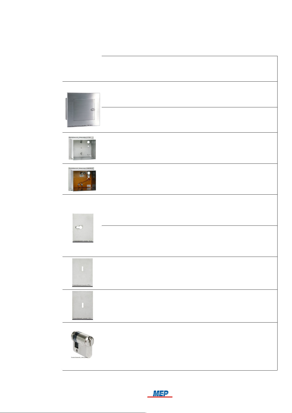
1.9 Product overview
The following table lists all types of Series FSK700 Fire Brigade Key Safes, as well as available
accessory parts.
• MEP Article No.
• Name
• Type
• Notes
• 265740
• Fire Brigade Key Safe
• FSK700-2
• For safekeeping of one master key
• 265742
• Fire Brigade Key Safe
• FSK700-2SX
• For safekeeping of two master keys, with upgrade options for up to four master keys
• 265751
• Flush Mounting Frame
• EZ700-2
• For installation of Key Safe FSK700-2 or FSK700-2SX in a solid wall
9
• 265818
• Flush Mounting Frame with All-Side Drill Protection
• EZBS700-2
• For installation of Key Safe FSK700-2 or FSK700-2SX in the Key Safe Column or
a wall with thermal insulation.
• 265752
• Inner Door for FSK700-2/2SX/PHZ/30.5mm
• ITA-2
• Includes pre-installed lock for locking cylinders compliant with VdS 2156 Class B,
with a length of 30.5mm. Locking cylinder is not included!
• 265748
• Inner Door for FSK700-2/2SX/PHZ/35.5mm
• ITA-3
• Includes pre-installed lock for locking cylinders compliant with VdS 2156 Class B,
with a length of 35.5mm. Locking cylinder is not included!
• 265753
• Inner Door for FSK700-2/2SX/DBUS
• ITB-2
• For double-bit variable lock type 2 or type 2005. Lock is not included!
• 265757
• Inner Door for FSK700-2/2SX/DBUS
• ITF-2
• For double-bit variable lock type Mauer 70091/70092. Lock is not included!
• 265744
• Auxiliary Locking Cylinder for FSK700-2/2SX
• PHZ700-2
• Common key locking cylinder, total length 36.3mm, key bit position of 0°.
An auxiliary locking cylinder is used if special master keys (e.g., electronic keys,
transponders, etc.) are to be kept inside the Key Safe. These are inseparably
attached to the supplied key fitting the auxiliary locking cylinder using the included
quick link.
HB_FSK700_1020_9161690_Englisch_D.odt / 1022 D / AN9161690
ZN62163/38/9
10 Chapter 1 • Introduction User Manual FSK700-2 / FSK700-2SX
10
• 265743
• Locking Cylinder Mounting Bracket FSK700-2SX
• PHZAW700-2S1
• For upgrading Key Safe FSK700-2SX to be able to keep one additional master key
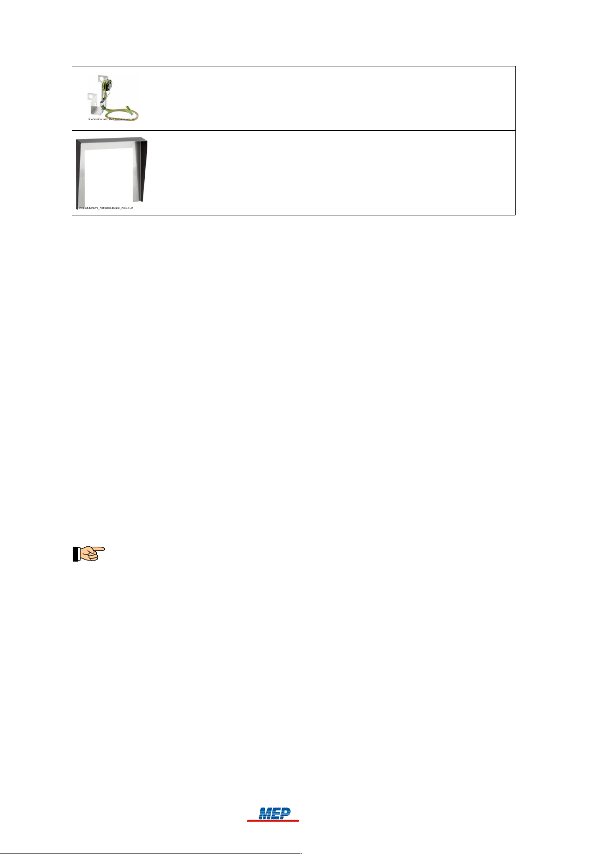
• 249650
• Weather Protection Hood for FSK700-2/2SX
• WSD-FSK
• Offers further protection of the Fire Brigade Key Safe against humidity if rain hits
the area around the outer door from above or from the sides
Table 1: Available accessory parts for the Series FSK700 Fire Brigade Key Safe
1.10 Special terms
Several of the technical / special terms that appear in this manual are defined herein. Take further
notice of the information given in the manual of the respectively used fire detection control panel.
Unblocking device
A key switch to which public safety services (e.g., fire brigade) possess a key, installed outside
the site, and with which fire alarm can be activated from outside the site. The fire alarm will
activate the transmitting device of the fire detection control panel, thus unlocking the outer door
of the Key Safe in which the master key is kept.
Auxiliary locking cylinder
An auxiliary locking cylinder is used if special master keys inapplicable for use with a locking
cylinder (e.g., electronic keys, transponders, etc.) are to be kept inside the Fire Brigade Key
Safe. The master keys are inseparably attached to the supplied key fitting the auxiliary locking
cylinder using the included quick link.
Key depot, termed "Key Safe" in the manual
Solid two-door container, which can be unlocked remotely, used for the safekeeping of master
keys. A key depot consists of a mechanically stable case, of which the outer door can be electromagnetically unlocked by an unlocking device. Located inside the key depot is an inner door, to
which the key is in the possession of, e.g., the fire brigade or a security company alone. The
master keys are kept behind the inner door. The key depot, as well as the keys kept inside are
under electronic surveillance. The keys are thus protected from unauthorised access, yet quickly
reachable by the fire brigade in case of emergency.
Definition from VdS-Richtlinie 2105: "4.2.4. Key depot 3 (SD3) – equal to DIN 14675 – FSD 3.
A container installed in a solid outer wall of a building. The keys kept inside the container enable
entry to secured areas. Monitoring of the key depot is required. The key depot is connected to an
alarm detection control panel."
Key depot control
Key depot control incorporates all functions required for controlling and monitoring of a key
depot. It can be available as part of an external device (e.g., fire detection control panel), a discrete module (e.g., circuit board), or a separate device.
Key depot controlling and monitoring device
Key depot control variant, available as a separate device or discrete module (e.g., a slide-in
module for an alarm system).
Transmitting device for alarm transmission
Transmitting devices receive messages from alarm systems, process them for transmission via
transmission paths, and serve as interface for these transmission paths. Furthermore, transmitting devices process the commands given by the alarm receiving device and transmit them to the
connected alarm system.
HB_FSK700_1020_9161690_Englisch_D.odt / 1022 D / AN9161690
ZN62163/38/10

User Manual FSK700-2 / FSK700-2SX Chapter 1 • Introduction 11
Confirmation signal
11
Signal transmitted to the fire detection control panel by the transmitting device, serving as confirmation of the successful activation of the transmitting device.
Variable lock
Lock that can be converted to use a new key code without replacing the tumblers.
1.11 Standards, Guidelines, CE marking
This manual contains dated and undated references to relevant standards. These references appear
in the appropriate sections of the manual, the titles of these standards are listed below. The latest
version of the respective standards are in effect.
DIN 14675 / App. C Fire detection and fire alarm systems - Design and operation
VdS 2105 Schlüsseldepots (SD) - Anforderungen an Anlagenteile
VdS 2350 Schlüsseldepots (SD) - Planung, Einbau und Instandhaltung
DIN 1053 Masonry
DIN 106 Calcium silicate units with specific properties
DIN 1045 Concrete, reinforced and prestressed concrete structures
DIN 49020 Conduit for Electrical Wiring; Screwed Steel Conduit, Plain Conduit,
Couplers
The CE marking on the Series FSK700 Fire Brigade Key Safe is done in accordance with Directive
2004/108/EC of the European Parliament and of the Council regarding Electromagnetic Compatibility (EMC). With the CE marking, see page 38 in chapter 8.2: "EC Declaration of Conformity", the
manufacturer confirms that the product conforms to EMC Directive 2004/108/EC.
1.12 Warranty
All parts of the Series FSK700 Fire Brigade Key Safe by MEP are manufactured with highest precision and utmost care. Nonetheless, the occurrence of malfunctions during operation cannot be
ruled out entirely. To register a complaint, please contact the company responsible for installation
of your system.
While the warranty period is in effect, all parts that become defective because of a demonstrable
flaw in their manufacture or in material will be either replaced or repaired free of charge. In such
cases, the time period of the original warranty will not be extended, nor will a new warranty period
be set for the replaced or repaired parts. All further claims are excluded, especially those regarding
reductions of the purchase price, cancellation of contract, compensatory damages or replacement
due to secondary damages of any type. Beyond these regulations, the current regulations of the
"General Terms of Delivery" that are issued by the Austrian Electrical and Electronics Industry
Association are in effect.
HB_FSK700_1020_9161690_Englisch_D.odt / 1022 D / AN9161690
ZN62163/38/11
12 Chapter 2 • Function User Manual FSK700-2 / FSK700-2SX
12
2 Function
The Series FSK700 Key Safe features independently operating sensors and actuators. The logical
operations between the signals of the sensors and actuators are made by the corresponding monitoring equipment (such as Key Safe Controlling and Monitoring Device AD900-1, MEP Article No.
265900), which acts as intelligent interface between the Key Safe and the fire detection control
panel or burglar alarm system.
1)
See page 13 onwards in chapter 2.4: "Fire alarm reset"
2)
With integrated temperature-controlled panel heating
3)
With one master key
4)
With double-bit variable lock and inserted key
Fig. 3: Fire Brigade Key Safe FSK700-2, displayed with doors open
2.1 Normal condition
The Fire Brigade Key Safe is in normal condition if:
the master key/all master keys are inserted correctly,
the inner door is closed,
the key to the inner door has been removed,
the outer door is closed, and
the unlocking device of the Key Safe has not been activated.
In normal condition, the electromagnet of the outer door closure device is rendered currentless.
2.2 Fire alarm condition
Fire alarm is reported to the fire brigade by the fire detection control panel using a transmitting
device. The fire brigade will transmit the confirmation signal, which, via the controlling and monitoring device, electromagnetically unlocks the outer door of the Key Safe – the outer door is thereby
cleared for opening.
The outer door does not open automatically after unlocking.
After opening the outer door, the inner door can be accessed. Using the key in possession of the fire
brigade, the inner door can be opened, and the master key(s) obtained.
In this state, monitoring of opening or sabotage of the Key Safe, as well as – if available – monitoring of the Flush Mounting Frame with Drill Protection and the Key Safe Column is disabled.
In special application cases, unlocking of the outer door must only be performed when, supplementary to the confirmation signal, the fire detection control panel is in fire alarm condition. The
Key Safe Controlling and Monitoring Device AD900-1 by MEP is equipped for this special
application, featuring two unlocking inputs, which can be connected via a logical AND operation
(AD900-1 / S2-1 switched "ON").
HB_FSK700_1020_9161690_Englisch_D.odt / 1022 D / AN9161690
ZN62163/38/12
 Loading...