


Fire Brigade Key Safe
FSK700-2 / FSK700-2SX
User Manual
Description
Installation - Connection – Commissioning - Maintenance
VdS Approval: G 199055
© by MEP-Gefahrenmeldetechnik GmbH


User Manual FSK700-2 / FSK700-2SX 3
Contents
1 Introduction................................................................................................................................... 5
1.1 General............................................................................................................................................5
1.2 Description of the Series FSK700 Key Safe...................................................................................5
1.2.1 Main features of the Series FSK700 Key Safe............................................................................. 6
1.3 Types of signs................................................................................................................................. 7
1.4 Outline of the manual......................................................................................................................7
1.5 Abbreviations..................................................................................................................................7
1.6 Important advice for the operator and specialist installer................................................................7
1.7 Cleaning the Series FSK700 Fire Brigade Key Safe.......................................................................8
1.8 Product contents.............................................................................................................................. 8
1.9 Product overview............................................................................................................................ 9
1.10 Special terms................................................................................................................................. 10
1.11 Standards, Guidelines, CE marking..............................................................................................11
1.12 Warranty.......................................................................................................................................11
2 Function........................................................................................................................................ 12
2.1 Normal condition.......................................................................................................................... 12
2.2 Fire alarm condition......................................................................................................................12
2.3 Activation of the unblocking device.............................................................................................13
2.4 Fire alarm reset............................................................................................................................. 13
2.5 Sabotage alarm.............................................................................................................................. 13
3
3 Installation....................................................................................................................................14
3.1 General..........................................................................................................................................14
3.2 Installation site.............................................................................................................................. 14
3.3 Installation of Flush Mounting Frame EZ700-2 or Flush Mounting Frame with
Drill Protection EZBS700-2..........................................................................................................15
3.4 Installation of Flush Mounting Frame EZ700-2 or Flush Mounting Frame with
Drill Protection EZBS700-2 in Key Safe Column SDS700-2.......................................................15
3.5 Preparation of the Fire Brigade Key Safe......................................................................................15
3.5.1 Removal of the inner door angle................................................................................................16
3.5.2 Installation of a locking half cylinder in the Locking Cylinder Mounting Bracket.....................16
3.5.3 Installation of additional locking half cylinders in Key Safe FSK700-2SX................................17
3.5.4 Installation of the inner door......................................................................................................18
3.6 Installation of the Fire Brigade Key Safe in the Flush Mounting Frame.......................................19
4 Connection.................................................................................................................................... 20
4.1 Preparation of the connection cables.............................................................................................20
4.2 Inner view of the Fire Brigade Key Safe.......................................................................................21
4.3 Layout of Connection Board APL-4.............................................................................................21
4.4 Connecting....................................................................................................................................22
4.4.1 Complete connection diagram.................................................................................................... 22
4.4.2 Connecting the Flush Mounting Frame with Drill Protection, or the Tamper Switch
of the Key Safe Column............................................................................................................. 24
4.4.3 Heating device of the Series FSK700 Fire Brigade Key Safe.....................................................24
4.5 Connecting the cables of the Key Safe to Connection Board APL-4............................................24
4.5.1 Ribbon cable of the outer door...................................................................................................25
4.5.2 Cable of the closure device.........................................................................................................25
4.5.3 Connecting the cables of the Locking Cylinder Mounting Brackets...........................................25
4.6 Typical connection diagram of a fire detection control panel and the Fire Brigade Key Safe.......26
4.6.1 Connection diagram of a system comprising fire detection control panel,
Series FSK700 Key Safe, Key Safe Controlling and Monitoring Device AD900-1,
and Power Supply Unit NT700-1...............................................................................................26
4.6.2 Connection diagram of a system comprising fire detection control panel,
HB_FSK700_1020_9161690_Englisch_D.odt / 1022 D
ZN62163/38/3

4 User Manual FSK700-2 / FSK700-2SX
4
burglar alarm control panel, and Fire Brigade Key Safe.............................................................26
4.6.3 Connection diagram of a system comprising burglar alarm control panel and
Fire Brigade Key Safe, without fire detection control panel.......................................................27
5 Commissioning............................................................................................................................28
5.1 General..........................................................................................................................................28
5.2 Notes on insurance protection....................................................................................................... 28
5.3 Configuration with jumpers..........................................................................................................28
5.3.1 Activation temperature of the outer door heating device............................................................28
5.3.2 Acoustic warning signal when missing master key....................................................................28
5.3.3 Automatic deactivation of the release magnet when outer door is open.....................................29
5.4 Commissioning instructions..........................................................................................................29
6 Inspection, maintenance, service............................................................................................. 32
6.1 Inspection, maintenance................................................................................................................ 32
6.2 Advice on fault correction of electrical parts................................................................................33
7 Technical specifications.............................................................................................................35
7.1 Fire Brigade Key Safe FSK700-2, FSK700-2SX..........................................................................35
7.2 Inner doors.................................................................................................................................... 35
7.2.1 Inner Door for FSK700-2/2SX/PHZ/30.5mm ITA-2..................................................................35
7.2.2 Inner Door for FSK700-2/2SX/PHZ/35.5mm ITA-3..................................................................35
7.2.3 Inner Door for FSK700-2/2SX/DBUS ITB-2.............................................................................36
7.2.4 Inner Door for FSK700-2/2SX/DBUS ITF-2.............................................................................36
7.3 Flush Mounting Frames................................................................................................................36
7.3.1 Flush Mounting Frame EZ700-2................................................................................................36
7.3.2 Flush Mounting Frame with Drill Protection EZBS700-2..........................................................36
7.4 Locking Cylinder Mounting Bracket for FSK700-2SX PHZAW700-2S1....................................36
7.5 Auxiliary Locking Cylinder for FSK700-2/2SX PHZ700-2..........................................................36
7.6 Weather Protection Hood for FSK700-2/2SX WSD-FSK.............................................................36
8 Certifications................................................................................................................................37
8.1 VdS Certificate.............................................................................................................................37
8.2 EC Declaration of Conformity......................................................................................................38
Safety Instructions
Prior to installing, operating, or providing maintenance to the products described herein,
the respective chapters of this manual must strictly be read, and especially the safety
information on page 7 and onwards in chapter 1.6 "Important advice for the operator and
specialist installer" must be implicitly observed and followed.
Furthermore, the pictographs on page 7 in chapter 1.3: "Types of signs" are highly
important – the many passages in this manual marked by these pictographs contain warnings of dangers that can arise from inappropriate usage of the product, as well as other
valuable advice.
Described in this manual is the range of functions of the Fire Brigade Key Safes FSK700-2
and FSK700-2SX (combinedly termed "Series FSK700") with Connection Board APL-4
(version number PN60046V2-H005) and Door Protection Board BOHR-4 (version number PN60047V1-H002). Outer dimensions are applicable from production number
08/06806 onwards. The functionality of units with a different production number can differ from the description in this manual in some points.
HB_FSK700_1020_9161690_Englisch_D.odt / 1022 D / AN9161690
ZN62163/38/4
User Manual FSK700-2 / FSK700-2SX Chapter 1 • Introduction 5
1 Introduction
1.1 General
Fire Brigade Key Safes serve for the theft-proof, copy-protected safekeeping of master keys, allowing the Fire Brigade to enter a building swiftly and without use of force in the event of fire.
The Fire Brigade Key Safe is installed in the entry area of the respective site. Upon alarm activation of the fire detection system, the outer door is unlocked remotely by the fire brigade, granting
access to the inner door of the Key Safe.
1.2 Description of the Series FSK700 Key Safe
Fire Brigade Key Safes FSK700-2 and FSK700-2SX (combinedly termed "Series FSK700"), as
manufactured by MEP-Gefahrenmeldetechnik GmbH (abbreviated "MEP" hereafter), are distinguished by application of solid, high-quality materials, as well as intelligent details in design,
achieving high security against unauthorised taking of master keys. Furthermore, master keys can
be secured by integrating the electric surveillance devices of the Key Safe in a burglar alarm system.
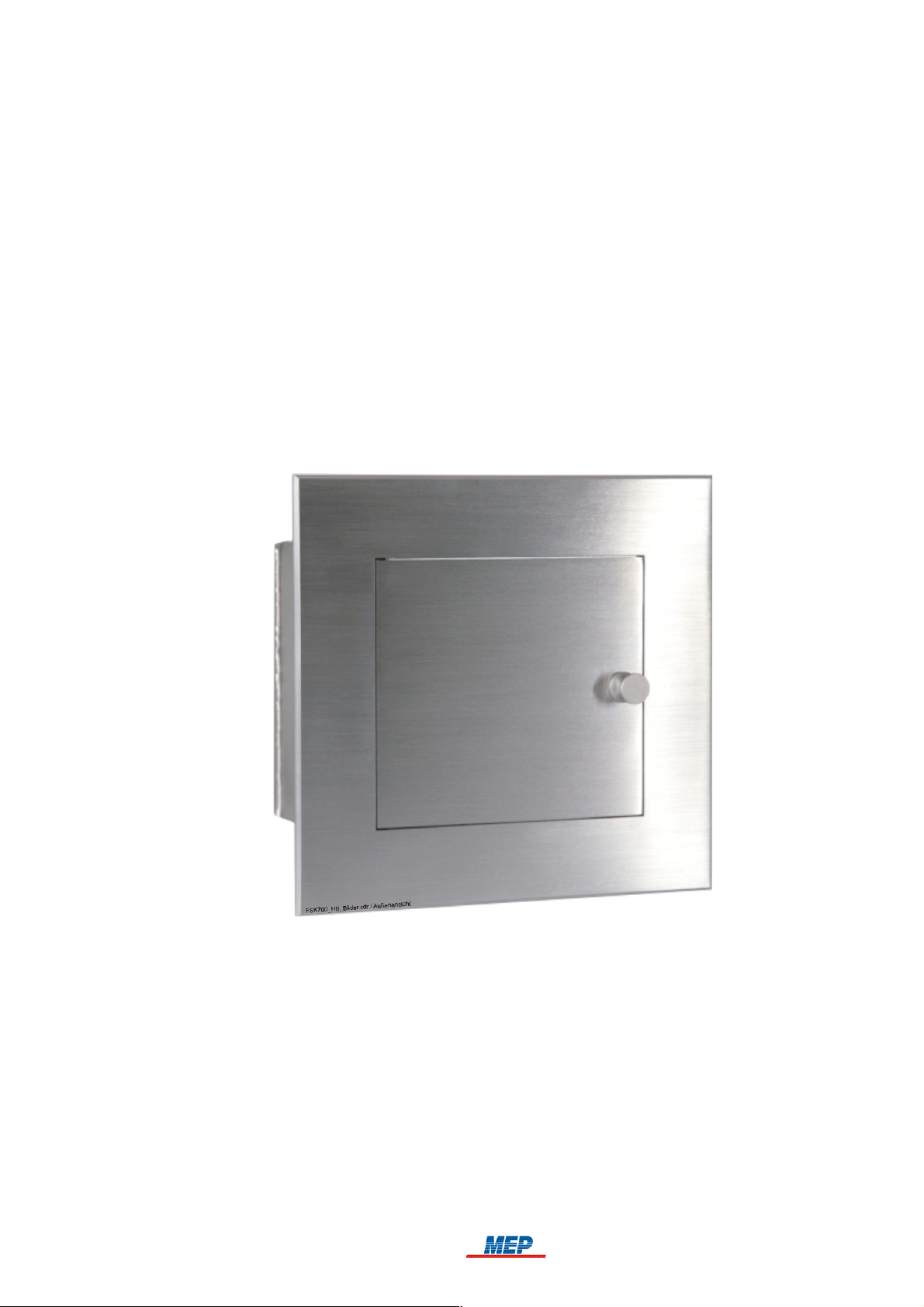
5
Fig. 1: Series FSK700 Fire Brigade Key Safe – front view
Series FSK700 consists of
Key Safe FSK700-2 (MEP Article No. 265740), in which one master key can be kept,
Key Safe FSK700-2SX (MEP Article No. 265742), of which the basic version can keep up to
two master keys, and can be upgraded with two Locking Cylinder Mounting Brackets to keep a
total of four master keys,
a range of accessory parts, described in chapter 1.9: "Product overview", from page 9 onwards.
HB_FSK700_1020_9161690_Englisch_D.odt / 1022 D / AN9161690
ZN62163/38/5
6 Chapter 1 • Introduction User Manual FSK700-2 / FSK700-2SX
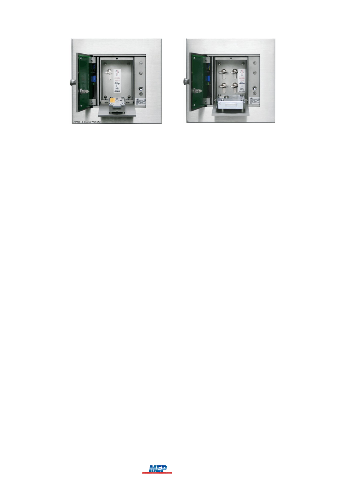
6
Fig. 2: Series FSK700 Fire Brigade Key Safe
On the left: FSK700-2 with open outer and inner doors, master key inserted, inner door fitted
with a double-bit variable lock
On the right: FSK700-2SX with 4 master keys, open outer and inner doors, inner door fitted with
a lock for a locking half cylinder
1.2.1 Main features of the Series FSK700 Key Safe
The Series FSK700 Key Safe has been tested and certified (Certification No. G 199055) by VdS
Schadenverhütung GmbH (VdS). In combination with a VdS-certified Key Safe controlling and
monitoring device, it can be employed together with most commercially available 12V or 24V fire
detection and burglar alarm systems.
The Series FSK700 Key Safe conforms to DIN 14675 Appendix C – Class 3 (FSD 3, high risk).
Up to four master keys can be stored inside a Fire Brigade Key Safe, thus meeting even complex
organisational requirements.
Due to intelligent details in design – for instance, protected outer door hinges – high security
against unauthorised opening is achieved.
The self-adjusting magnetic closure device automatically assumes the optimal position – therefore,
the closure device is able to function at the highest precision level, even during long-time opera-
tion under unfavourable temperatures or environmental conditions.
To guarantee high corrosion resistance and mechanical stability, all vital mechanical parts are
made from stainless steel.
Installation of the Key Safe is easy and smooth due to the Flush Mounting Frame introduced
many years ago in Germany by MEP.
An acoustic warning signal will sound from the Key Safe if not all master keys have been inserted
correctly.
For application of different locking mechanisms, such as double-bit variable locks or locking half
cylinders, suitable inner doors are available.
To assure unhindered opening of the Key Safe at low outside temperatures, the outer door can be
electrically heated with 12V or 24V AC or DC. Heating is controlled by temperature, operating
only at temperatures below +10°C (at factory default settings).
Adaption of the magnetic closure device and heating device to different voltages (12V or 24V) is
performed automatically by all Series FSK700 units, guaranteeing quick and problem-free commissioning.
HB_FSK700_1020_9161690_Englisch_D.odt / 1022 D / AN9161690
ZN62163/38/6
User Manual FSK700-2 / FSK700-2SX Chapter 1 • Introduction 7
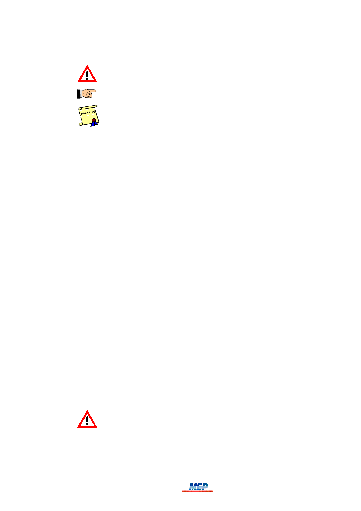
1.3 Types of signs
Especially important passages in this manual are marked with signs. The following signs are used:
ATTENTION! Disregard of this reference can lead to malfunction or damage to the unit.
TIP! This passage contains notes that will help ease operation.
The country-specific and/or the site-specific requirements of the device and/or system
APPROVALS must be observed.
1.4 Outline of the manual
Following the safety instructions on page 4, and guidelines given in the first chapter, which
should be implicitly observed,
chapter two contains all information required to operate a Series FSK700 Fire Brigade Key
Safe. It is explained how the Fire Brigade Key Safe works in combination with a fire detection
control panel, a controlling and monitoring device, an unblocking device, and a transmitting
device, as well as describing in which situations sabotage alarm is activated.
7
In chapter three, relevant guidelines for the installation of the Fire Brigade Key Safe by a spe-
cialist installer are given.
In chapter four, the specialist installer is provided with an overview of the arrangement of ter-
minals, connectors, and other important elements, as well as information required to connect
the Fire Brigade Key Safe to an MEP Key Safe Controlling and Monitoring Device AD900-1,
and to a fire detection control panel.
In chapter five, commissioning of the Fire Brigade Key Safe is described in detail for the spe-
cialist installer.
In chapter six, notes on inspection and maintenance of the unit are given. Also described in
this chapter are possible causes of malfunction and steps to correct them.
In chapter seven, all essential technical specifications of the unit are presented.
In chapter eight, copies of the VdS-Prüfzertifikat and the EC Declaration of Conformity are
provided.
1.5 Abbreviations
The correct designations for both Key Safe types "Fire Brigade Key Safe FSK700-2" and "Fire Brigade Key Safe FSK700-2SX" are shortened to "Fire Brigade Key Safe", "Key Safe", or "Series
FSK700" for improved readability of the manual. Differences between the two types are noted in
the respective text passages.
1.6 Important advice for the operator and specialist installer
The keeping of keys in a Fire Brigade Key Safe results in an increased level of danger, which the
insurance company must be informed of.
If the key depot is not VdS-certified and/or is not installed, operated and maintained
according to the VdS-Richtlinien für Schlüsseldepots, Planung, Einbau und Instandhaltung
(VdS 2350), it is possible that no insurance protection is available for damages due to burglary, in case the building has been opened using the (real) key taken from the key depot.
The Fire Brigade Key Safe must only be used in combination with components recommended or
certified by the manufacturer, and exclusively for the application described in the manual.
HB_FSK700_1020_9161690_Englisch_D.odt / 1022 D / AN9161690
ZN62163/38/7

8 Chapter 1 • Introduction User Manual FSK700-2 / FSK700-2SX
8
For the safe operation of the Fire Brigade Key Safe, appropriate transport, storage, installation,
commissioning, inspection, proper maintenance and correction of malfunctions, as well as careful
and competent handling are required.
Fire detection systems and devices must, on principle, be installed by and receive maintenance
from regularly trained technical staff only. Special training for technical staff must be performed by
MEP-Gefahrenmeldetechnik GmbH (MEP) or personnel expressly authorised by MEP. Country-specific standards, rules and regulations, or instructions by MEP must be strictly abided.
For proper functioning of the fire detection system, all devices must be installed according to regulations, and supplied with voltage. It must be ensured that all units are suitable to use under expected environmental conditions.
All work on the componentry of the Fire Brigade Key Safe must be performed without
voltage. Installation must be thoroughly checked prior to supplying voltage.
Regular maintenance based on country-specific standards must be performed on fire detection systems. Required repairs are to be promptly performed.
The locking bolt must only be installed in the outer door after both the Fire Brigade Key
Safe and the connected controlling and monitoring device are fully operational!
Also take note of the advice given from page 15 onwards in chapter 3.5: "Preparation of the
Fire Brigade Key Safe", as well as from page 29 onwards in chapter 5.4: "Commissioning
instructions".
1.7 Cleaning the Series FSK700 Fire Brigade Key Safe
Series FSK700 Key Safes are manufactured from stainless steel, and as such are – apart from
providing high mechanical stability – mostly corrosion-free. Residue of steel or iron (e.g., grit produced by brake discs of motorised vehicles), however, can rust and penetrate the corrosion protection layer of almost any high-grade steel – this can, after prolonged exposure, leave traces of corrosion on the Key Safe itself.
To prevent this, the front side of the Key Safe should regularly be cleaned using a plain, non-abrasive cleaning aid. Afterwards, special products for care of stainless steel should be applied to the
surface.
Under no circumstances use abrasive detergents – this would scratch the finely polished surface
of the Key Safe!
1.8 Product contents
Series FSK700 Key Safes are 100% tested for operation, and are supplied with all materials necessary for installation, as well as a manual.
Outside the scope of delivery are Inner Doors, Flush Mounting Frames, Auxiliary Locking Cylinders, Weather Protection Hood, etc. These are listed in the following chapter 1.9: "Product overview", must be ordered, and will be delivered separately.
HB_FSK700_1020_9161690_Englisch_D.odt / 1022 D / AN9161690
ZN62163/38/8
User Manual FSK700-2 / FSK700-2SX Chapter 1 • Introduction 9
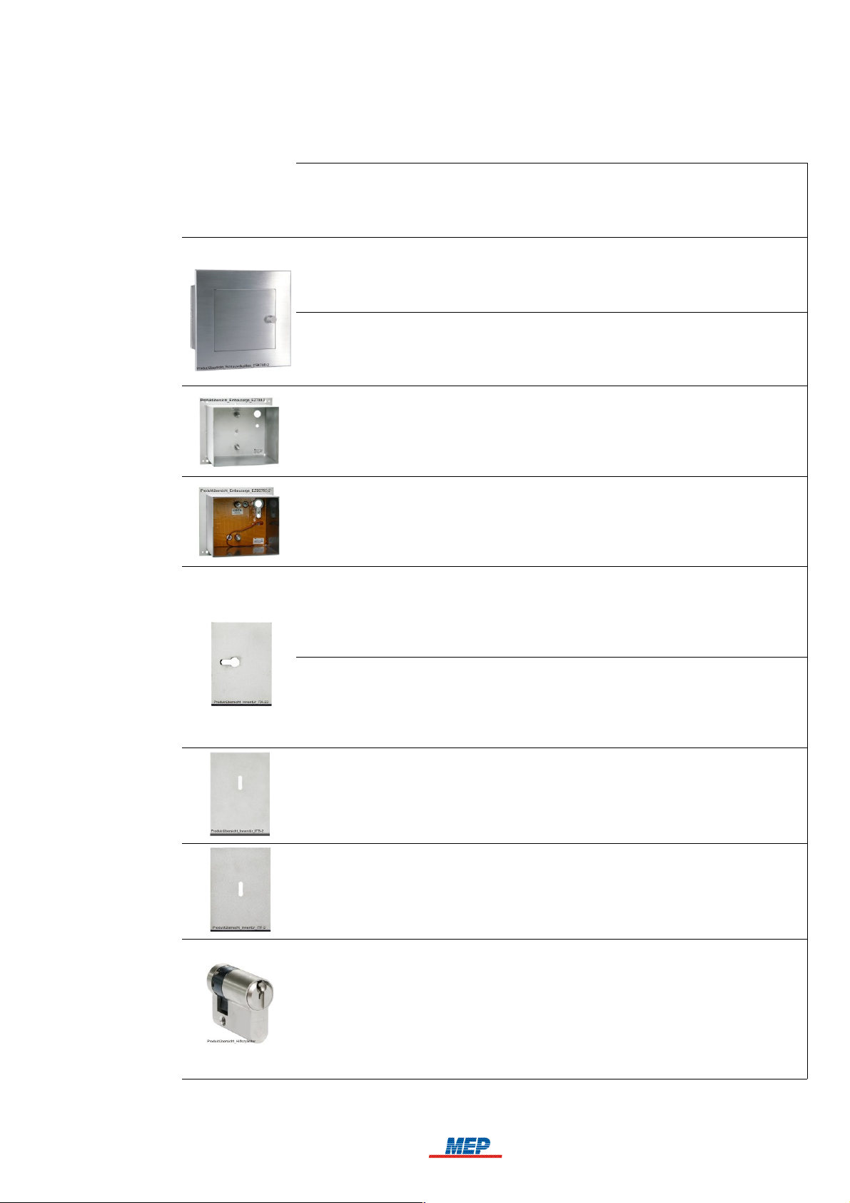
1.9 Product overview
The following table lists all types of Series FSK700 Fire Brigade Key Safes, as well as available
accessory parts.
• MEP Article No.
• Name
• Type
• Notes
• 265740
• Fire Brigade Key Safe
• FSK700-2
• For safekeeping of one master key
• 265742
• Fire Brigade Key Safe
• FSK700-2SX
• For safekeeping of two master keys, with upgrade options for up to four master keys
• 265751
• Flush Mounting Frame
• EZ700-2
• For installation of Key Safe FSK700-2 or FSK700-2SX in a solid wall
9
• 265818
• Flush Mounting Frame with All-Side Drill Protection
• EZBS700-2
• For installation of Key Safe FSK700-2 or FSK700-2SX in the Key Safe Column or
a wall with thermal insulation.
• 265752
• Inner Door for FSK700-2/2SX/PHZ/30.5mm
• ITA-2
• Includes pre-installed lock for locking cylinders compliant with VdS 2156 Class B,
with a length of 30.5mm. Locking cylinder is not included!
• 265748
• Inner Door for FSK700-2/2SX/PHZ/35.5mm
• ITA-3
• Includes pre-installed lock for locking cylinders compliant with VdS 2156 Class B,
with a length of 35.5mm. Locking cylinder is not included!
• 265753
• Inner Door for FSK700-2/2SX/DBUS
• ITB-2
• For double-bit variable lock type 2 or type 2005. Lock is not included!
• 265757
• Inner Door for FSK700-2/2SX/DBUS
• ITF-2
• For double-bit variable lock type Mauer 70091/70092. Lock is not included!
• 265744
• Auxiliary Locking Cylinder for FSK700-2/2SX
• PHZ700-2
• Common key locking cylinder, total length 36.3mm, key bit position of 0°.
An auxiliary locking cylinder is used if special master keys (e.g., electronic keys,
transponders, etc.) are to be kept inside the Key Safe. These are inseparably
attached to the supplied key fitting the auxiliary locking cylinder using the included
quick link.
HB_FSK700_1020_9161690_Englisch_D.odt / 1022 D / AN9161690
ZN62163/38/9
10 Chapter 1 • Introduction User Manual FSK700-2 / FSK700-2SX
10
• 265743
• Locking Cylinder Mounting Bracket FSK700-2SX
• PHZAW700-2S1
• For upgrading Key Safe FSK700-2SX to be able to keep one additional master key
• 249650
• Weather Protection Hood for FSK700-2/2SX
• WSD-FSK
• Offers further protection of the Fire Brigade Key Safe against humidity if rain hits
the area around the outer door from above or from the sides
Table 1: Available accessory parts for the Series FSK700 Fire Brigade Key Safe
1.10 Special terms
Several of the technical / special terms that appear in this manual are defined herein. Take further
notice of the information given in the manual of the respectively used fire detection control panel.
Unblocking device
A key switch to which public safety services (e.g., fire brigade) possess a key, installed outside
the site, and with which fire alarm can be activated from outside the site. The fire alarm will
activate the transmitting device of the fire detection control panel, thus unlocking the outer door
of the Key Safe in which the master key is kept.
Auxiliary locking cylinder
An auxiliary locking cylinder is used if special master keys inapplicable for use with a locking
cylinder (e.g., electronic keys, transponders, etc.) are to be kept inside the Fire Brigade Key
Safe. The master keys are inseparably attached to the supplied key fitting the auxiliary locking
cylinder using the included quick link.
Key depot, termed "Key Safe" in the manual
Solid two-door container, which can be unlocked remotely, used for the safekeeping of master
keys. A key depot consists of a mechanically stable case, of which the outer door can be electromagnetically unlocked by an unlocking device. Located inside the key depot is an inner door, to
which the key is in the possession of, e.g., the fire brigade or a security company alone. The
master keys are kept behind the inner door. The key depot, as well as the keys kept inside are
under electronic surveillance. The keys are thus protected from unauthorised access, yet quickly
reachable by the fire brigade in case of emergency.
Definition from VdS-Richtlinie 2105: "4.2.4. Key depot 3 (SD3) – equal to DIN 14675 – FSD 3.
A container installed in a solid outer wall of a building. The keys kept inside the container enable
entry to secured areas. Monitoring of the key depot is required. The key depot is connected to an
alarm detection control panel."
Key depot control
Key depot control incorporates all functions required for controlling and monitoring of a key
depot. It can be available as part of an external device (e.g., fire detection control panel), a discrete module (e.g., circuit board), or a separate device.
Key depot controlling and monitoring device
Key depot control variant, available as a separate device or discrete module (e.g., a slide-in
module for an alarm system).
Transmitting device for alarm transmission
Transmitting devices receive messages from alarm systems, process them for transmission via
transmission paths, and serve as interface for these transmission paths. Furthermore, transmitting devices process the commands given by the alarm receiving device and transmit them to the
connected alarm system.
HB_FSK700_1020_9161690_Englisch_D.odt / 1022 D / AN9161690
ZN62163/38/10

User Manual FSK700-2 / FSK700-2SX Chapter 1 • Introduction 11
Confirmation signal
11
Signal transmitted to the fire detection control panel by the transmitting device, serving as confirmation of the successful activation of the transmitting device.
Variable lock
Lock that can be converted to use a new key code without replacing the tumblers.
1.11 Standards, Guidelines, CE marking
This manual contains dated and undated references to relevant standards. These references appear
in the appropriate sections of the manual, the titles of these standards are listed below. The latest
version of the respective standards are in effect.
DIN 14675 / App. C Fire detection and fire alarm systems - Design and operation
VdS 2105 Schlüsseldepots (SD) - Anforderungen an Anlagenteile
VdS 2350 Schlüsseldepots (SD) - Planung, Einbau und Instandhaltung
DIN 1053 Masonry
DIN 106 Calcium silicate units with specific properties
DIN 1045 Concrete, reinforced and prestressed concrete structures
DIN 49020 Conduit for Electrical Wiring; Screwed Steel Conduit, Plain Conduit,
Couplers
The CE marking on the Series FSK700 Fire Brigade Key Safe is done in accordance with Directive
2004/108/EC of the European Parliament and of the Council regarding Electromagnetic Compatibility (EMC). With the CE marking, see page 38 in chapter 8.2: "EC Declaration of Conformity", the
manufacturer confirms that the product conforms to EMC Directive 2004/108/EC.
1.12 Warranty
All parts of the Series FSK700 Fire Brigade Key Safe by MEP are manufactured with highest precision and utmost care. Nonetheless, the occurrence of malfunctions during operation cannot be
ruled out entirely. To register a complaint, please contact the company responsible for installation
of your system.
While the warranty period is in effect, all parts that become defective because of a demonstrable
flaw in their manufacture or in material will be either replaced or repaired free of charge. In such
cases, the time period of the original warranty will not be extended, nor will a new warranty period
be set for the replaced or repaired parts. All further claims are excluded, especially those regarding
reductions of the purchase price, cancellation of contract, compensatory damages or replacement
due to secondary damages of any type. Beyond these regulations, the current regulations of the
"General Terms of Delivery" that are issued by the Austrian Electrical and Electronics Industry
Association are in effect.
HB_FSK700_1020_9161690_Englisch_D.odt / 1022 D / AN9161690
ZN62163/38/11
12 Chapter 2 • Function User Manual FSK700-2 / FSK700-2SX
12
2 Function
The Series FSK700 Key Safe features independently operating sensors and actuators. The logical
operations between the signals of the sensors and actuators are made by the corresponding monitoring equipment (such as Key Safe Controlling and Monitoring Device AD900-1, MEP Article No.
265900), which acts as intelligent interface between the Key Safe and the fire detection control
panel or burglar alarm system.
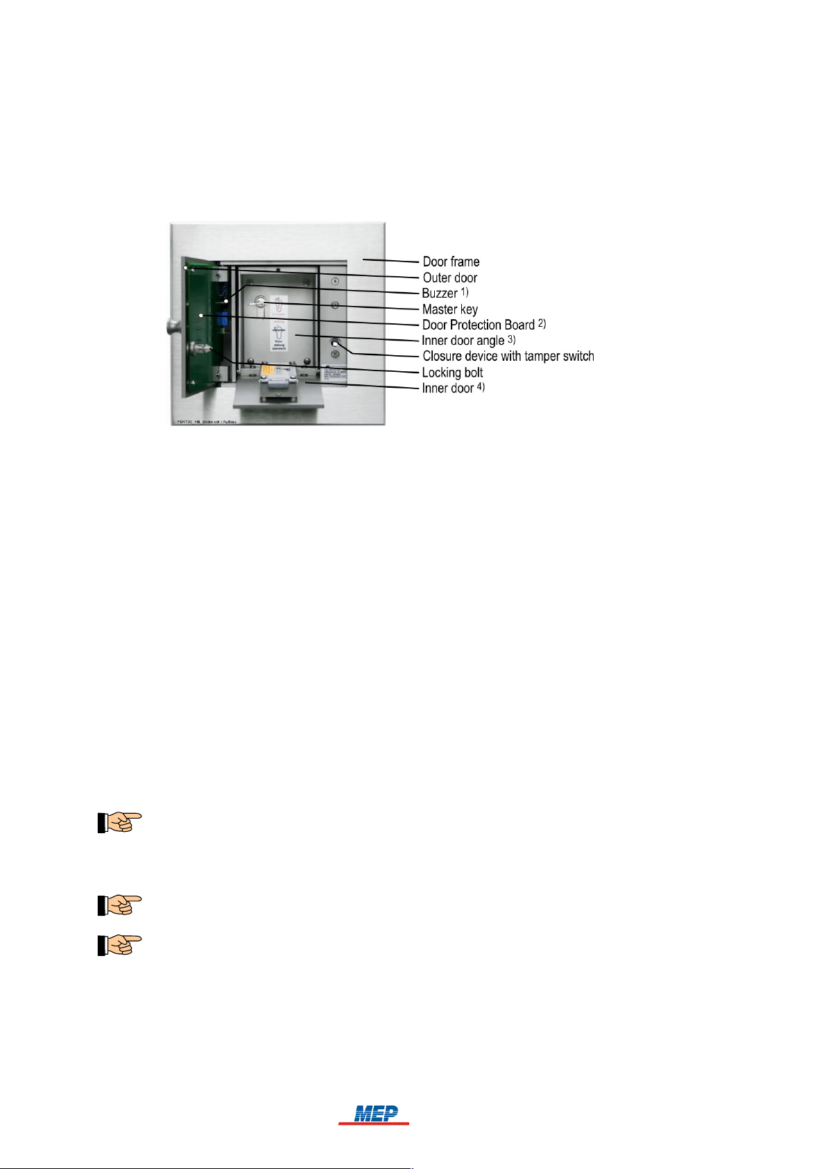
1)
See page 13 onwards in chapter 2.4: "Fire alarm reset"
2)
With integrated temperature-controlled panel heating
3)
With one master key
4)
With double-bit variable lock and inserted key
Fig. 3: Fire Brigade Key Safe FSK700-2, displayed with doors open
2.1 Normal condition
The Fire Brigade Key Safe is in normal condition if:
the master key/all master keys are inserted correctly,
the inner door is closed,
the key to the inner door has been removed,
the outer door is closed, and
the unlocking device of the Key Safe has not been activated.
In normal condition, the electromagnet of the outer door closure device is rendered currentless.
2.2 Fire alarm condition
Fire alarm is reported to the fire brigade by the fire detection control panel using a transmitting
device. The fire brigade will transmit the confirmation signal, which, via the controlling and monitoring device, electromagnetically unlocks the outer door of the Key Safe – the outer door is thereby
cleared for opening.
The outer door does not open automatically after unlocking.
After opening the outer door, the inner door can be accessed. Using the key in possession of the fire
brigade, the inner door can be opened, and the master key(s) obtained.
In this state, monitoring of opening or sabotage of the Key Safe, as well as – if available – monitoring of the Flush Mounting Frame with Drill Protection and the Key Safe Column is disabled.
In special application cases, unlocking of the outer door must only be performed when, supplementary to the confirmation signal, the fire detection control panel is in fire alarm condition. The
Key Safe Controlling and Monitoring Device AD900-1 by MEP is equipped for this special
application, featuring two unlocking inputs, which can be connected via a logical AND operation
(AD900-1 / S2-1 switched "ON").
HB_FSK700_1020_9161690_Englisch_D.odt / 1022 D / AN9161690
ZN62163/38/12

User Manual FSK700-2 / FSK700-2SX Chapter 2 • Function 13
13
2.3 Activation of the unblocking device
The unblocking device (a specially realised key switch – see, for example, Unblocking Device
FSE/PHZ900-1, MEP Article No. 265662) is connected to the fire detection control panel in the
same way as a manual call point. Upon activation of the unblocking device, fire alarm will be
activated, thus unlocking the outer door of the Fire Brigade Key Safe via the confirmation signal of
the transmitting device connected to the fire brigade.
Activation of the fire detection control panel by the unblocking device must not affect Fire Control procedures of the fire detection control panel.
2.4 Fire alarm reset
The outer door of the Key Safe will only lock again after the fire detection control panel is reset,
thereby terminating the confirmation signal, the/all master keys have been reinserted, and the inner
and outer door have been closed. Successful locking can be confirmed by pulling the outer door.
By locking the outer door, monitoring of opening or sabotage of the Key Safe, as well as – if
available – monitoring of the Flush Mounting Frame with Drill Protection and the Key Safe
Column will be reactivated.
Should a master key not have been inserted correctly after resetting the fire detection control panel,
a sustained buzzing tone generated by the Key Safe's integrated buzzer will sound upon closing the
outer door.
This function is only available if the Key Safe is connected to the Key Safe Controlling and
Monitoring Device AD900-1 by MEP (also see page 28 and onwards in chapter 5.3.2: "Acoustic
warning signal when missing master key").
If the Key Safe remains unopened during fire alarm, the outer door will be automatically locked
again upon termination of the confirmation signal, and monitoring of opening or sabotage of the
Key Safe, as well as – if available – monitoring of the Flush Mounting Frame with Drill Protection
and the Key Safe Column will be reactivated.
2.5 Sabotage alarm
The following states are constantly monitored by the Key Safe Controlling and Monitoring Device
AD900-1:
Outer door closed,
Drill Protection Board undamaged,
master keys correctly inserted,
Drill Protection of the Flush Mounting Frame undamaged (if available),
Tamper Switch of the Key Safe Column closed (if available).
The Key Safe Controlling and Monitoring Device AD900-1 will generate an alarm signal if – e.g.,
by forcefully breaking into the Key Safe – one of these monitored states is violated insofar as causing the monitor loop's resistance to deviate more than 40% from normal condition.
DIN 14675 / chapter C.2.2.3: The report (sabotage report) must, under application according to
Class FSD 3 (high risk), be forwarded to an office or authority that is available at all times, such
as a police department or security company.
If the Key Safe has been unlocked by the confirmation signal, sabotage monitoring is disabled
until a reset is performed correctly (see page 13 and onwards in chapter 2.4: "Fire alarm reset").
HB_FSK700_1020_9161690_Englisch_D.odt / 1022 D / AN9161690
ZN62163/38/13

14 Chapter 3 • Installation User Manual FSK700-2 / FSK700-2SX
14
3 Installation
3.1 General
Installation and commissioning of the Series FSK700 Fire Brigade Key Safe is to be performed by
a specialist company trained and authorised by MEP-Gefahrenmeldetechnik GmbH or their local
representative. All relevant standards and regulations must thereby be observed (see page 11 and
onwards in chapter 1.11: "Standards, Guidelines, CE marking").
1)
Optional Weather Protection Hood WSD-FSK
Fig. 4: Dimensions of the Series FSK700 Key Safe, starting from production number 08/06806
The Key Safe is to be inserted in the Flush Mounting Frame EZ700-2, MEP Article No. 265751,
which must be tightly grounded in the wall. Should the wall not be sufficiently solid (see page 14
and onwards in chapter 3.2: "Installation site"), the Flush Mounting Frame with Drill Protection
EZBS700-2, MEP Article No. 265818 must be utilised instead.
Instructions for installation of the Key Safe in the Key Safe Column SDS700-2 are provided in
the manual "Key Safe Column SDS700-2" by MEP-Gefahrenmeldetechnik GmbH.
Controlling and monitoring of the Key Safe must be performed using a VdS-certified controlling
and monitoring device (such as Key Safe Controlling and Monitoring Device AD900-1, MEP Article No. 265900).
Instructions for installation of the controlling and monitoring device are provided in the manual
of the respectively used device.
3.2 Installation site
The Key Safe is to be installed in accordance with the local fire brigade, preferably in a weatherproof location (i.e., in an alcove, passageway, or under a canopy), flush mounted in the wall. The
bottom edge of the Key Safe should be located about 1.2m (at least 0.8m) above the floor.
The wall in which the Key Safe (i.e., Flush Mounting Frame EZ700-2) is to be installed in must be
made from stone work according to DIN 1053, bricks according to DIN 105, lime-sand bricks
according to DIN 106, or from reinforced concrete (minimum B 25 according to DIN 1045). The
wall must be at least 80mm thicker than the installation depth of the Key Safe.
Should no adequately solid wall suitable for installation of the Key Safe be available (e.g., only
walls with thermal insulation), the Flush Mounting Frame with Drill Protection EZBS700-2 must
be utilised to improve security and protect against sabotage.
HB_FSK700_1020_9161690_Englisch_D.odt / 1022 D / AN9161690
ZN62163/38/14

User Manual FSK700-2 / FSK700-2SX Chapter 3 • Installation 15
15
3.3 Installation of Flush Mounting Frame EZ700-2 or Flush Mounting Frame with
Drill Protection EZBS700-2
1)
The front edge of the Flush Mounting Frame must not protrude from the wall
Fig. 5: Dimensions of Flush Mounting Frames EZ700-2 and EZBS700-2
The front edge of the Flush Mounting Frame must be flush-mounted to the wall surface (under no
circumstances must it protrude!) as best as possible. The bottom edge of the Key Safe should be
located about 1.2m (at least 0.8m) above the floor.
Installation of Flush Mounting Frames EZ700-2 and EZBS700-2 is to be performed according to
the manual provided with the Flush Mounting Frames.
Insert the Flush Mounting Frame into the prepared opening in the wall, and insert the conduits
for the connection cables, as well as for the protective earth into the Flush Mounting Frame
from behind.
Notice the required installation position (labelled: "OBEN / TOP SIDE – Einbauzarge
putzbündig einmauern!").
Fix the Flush Mounting Frame onto the installation surface.
Fill the remaining openings in the Flush Mounting Frame, as well as the inner space with suit-
able materials, to prevent mortar, cement, or similar from entering while setting the Flush
Mounting Frame into the wall.
Protect the drill protection film inlaid in the Flush Mounting Frame with Drill Protection EZB-
S700-2, and the connection cable from damage while setting the Flush Mounting Frame into the
wall.
Fix the Flush Mounting Frame in the wall.
3.4 Installation of Flush Mounting Frame EZ700-2 or Flush Mounting Frame with
Drill Protection EZBS700-2 in Key Safe Column SDS700-2
Instructions for installation in the Key Safe Column SDS700-2, with or without cement grouting
according to VdS guidelines 2105 and 2350, are found in the manual "Key Safe Column
SDS700-2" by MEP-Gefahrenmeldetechnik GmbH.
3.5 Preparation of the Fire Brigade Key Safe
The Series FSK700 Fire Brigade Key Safe must be fitted with the appropriate inner door, as well as
the locking cylinder(s) for the master key(s) or auxiliary locking cylinder(s). Installation of additional Locking Cylinder Mounting Brackets PHZAW700-2S1 along with appropriate locking cylinders is required for the Series FSK700-2SX Key Safe if more than two master keys are to be kept.
It is possible to perform the following tasks on an already installed Key Safe – however, it is
recommended to complete preparation of the Key Safe before installation in the Flush Mounting
Frame.
HB_FSK700_1020_9161690_Englisch_D.odt / 1022 D / AN9161690
ZN62163/38/15

16 Chapter 3 • Installation User Manual FSK700-2 / FSK700-2SX
16
The locking bolt supplied in the accessory kit must only be installed in the outer door after
both the Fire Brigade Key Safe and the connected controlling and monitoring device are
fully operational! Should the electrical unlocking device not be fully operational upon closing the outer door with installed locking bolt, the Key Safe can only be opened again by
means leading to the destruction of some of its componentry (e.g., outer door, Drill Protection Board). Additional advice can be found on page 29 and onwards in chapter 5.4: "Commissioning instructions".
3.5.1 Removal of the inner door angle
For the tasks of installing the Fire Brigade Key Safe in the Flush Mounting Frame, setting up cable
connections, as well as for the installation of the locking cylinder(s) for the master key(s), the inner
door angle must be removed.
Removal of the inner door angle is to be performed as follows:
Open the outer and inner doors.
Remove all master keys.
Remove the 4 mounting screws on the inner door angle (see Fig. 6 below).
Pull out the inner door angle in a forward direction.
Fig. 6: Location of the mounting screws for the inner door angle
The figure shows an already installed locking cylinder for the master key, as well as an inner
door including lock – these parts are not pre-installed in a newly shipped Key Safe!
Reinstallation of the inner door after completion of the planned tasks is to be performed with the
steps in reverse order.
3.5.2 Installation of a locking half cylinder in the Locking Cylinder Mounting Bracket
Depending on the case of application, either a locking half cylinder identical to the locking mechanisms used on-site, or alternatively, an auxiliary locking cylinder (see page 10 and onwards in
chapter 1.10: "Special terms") must be installed.
Locking cylinders that meet the requirements listed in the technical specifications on page 35 and
onwards in chapter 7.1: "Fire Brigade Key Safe FSK700-2, FSK700-2SX" are to be used exclusively.
Remove the inner door angle, see page 16 and onwards in chapter 3.5.1: "Removal of the inner
door angle".
Adjust the locking cam of the locking half cylinder so that it points downwards when assuming
the key removal position, see Fig. 7 below.
Fig. 7: Position of the locking cam with key removed
Insert the locking half cylinder into the Locking Cylinder Mounting Bracket and fix it in place
using the M5×12mm hex head screw included in the accessory kit.
HB_FSK700_1020_9161690_Englisch_D.odt / 1022 D / AN9161690
ZN62163/38/16

User Manual FSK700-2 / FSK700-2SX Chapter 3 • Installation 17
Check the detent and proper triggering of the micro switch by the locking cam.
Check if the label showing the key removal position, found on the inner door angle, conforms
17
with the installed locking half cylinder for the master key. An alternative label showing a horizontal key removal position is included in the accessory kit of the Key Safe, see Fig. 8 below.
Fig. 8: Label showing key removal position of the locking half cylinder designated for the master key
(key removal position on top)
On the left: factory default label
On the right: alternative label showing horizontal key removal position
3.5.3 Installation of additional locking half cylinders in Key Safe FSK700-2SX
Fire Brigade Key Safe FSK700-2SX is factory-equipped with two Locking Cylinder Mounting
Brackets. Using the supplementary Locking Cylinder Mounting Brackets PHZAW700-2S1, Key
Safe FSK700-2SX can be upgraded to up to four locking half cylinders.
A Locking Cylinder Mounting Bracket PHZAW700-2S1 is required for every additional locking
half cylinder.
Key Safe type FSK700-2 is not applicable for installation of additional locking half cylinders.
Installation is to be performed as follows:
Remove the inner door angle, see page 16 and onwards in chapter 3.5.1: "Removal of the inner
door angle".
Adjust the locking cam of the locking half cylinder so that it points downwards when assuming
the key removal position, see Fig. 7 above.
Insert the locking half cylinder into the Locking Cylinder Mounting Bracket and fix it in place
using the M5×12mm hex head screw included in the accessory kit.
Install the Locking Cylinder Mounting Bracket including locking half cylinder in the next avail-
able install position, see Fig. 9 below, left-hand picture. The required M4 nuts are included in
the accessory kit of the Locking Cylinder Mounting Bracket.
The cables leading from the Locking Cylinder Mounting Brackets should only be connected to
the Connection Board after all cables leading from the controlling and monitoring device have
been connected. See page 25 and onwards in chapter 4.5.3: "Connecting the cables of the Locking Cylinder Mounting Brackets".
HB_FSK700_1020_9161690_Englisch_D.odt / 1022 D / AN9161690
ZN62163/38/17

18 Chapter 3 • Installation User Manual FSK700-2 / FSK700-2SX
18
Fig. 9: Arrangement of locking half cylinders for master keys in Key Safe FSK700-2SX
On the left: install positions for 4 Locking Cylinder Mounting Brackets in Key Safe
FSK700-2SX
On the right: breaking points for locking half cylinders 3 and 4 on the inner door angle
The appropriate breaking point for every additional locking half cylinder must be opened up on
the inner door angle, for example, using a flat chisel and applying a few soft hammer blows.
3.5.4 Installation of the inner door
All installation materials required for installation are included in the accessory kit provided with
the respective inner door.
Installation of the inner door can be performed more easily after removing the inner door angle
(see page 16 and onwards in chapter 3.5.1: "Removal of the inner door angle").
The locking mechanism to be used in the inner door (i.e., locking half cylinder, variable lock) is
to be determined by local authorities.
Install the variable lock in the inner door, or, with inner doors ITA-2 an ITA-3, insert the lock-
ing half cylinder into the lock and fix it using an M5×65mm countersunk head screw, see Fig.
10 below, right-hand picture (detail "A").
Fix the inner door on the inner door angle using two M4×6mm screws, see Fig. 10 below, left-
hand picture (detail "B"). The shaped recesses in the door bearings must face the inner door.
Fig. 10: Installation of the inner door
On the left: detail "A": Screw fixing the locking half cylinder in Inner Doors ITA-2 and ITA-3
detail "B": Fixing the inner door to the door bearings
detail "C": Screw used for limiting the angle of rotation
On the right: View of the inner door angle from behind/above. The clearance of the locked inner
door is adjusted with the M5 grub screw on the door stop bar. Fix the adjustment setting using
the M5 counter nut.
Insert the M5 grub screw in the upper door stop bar of the inner door angle, but tighten it only
as much so that sufficient clearance is guaranteed when the inner door is closed (see Fig. 10
above, right-hand picture).
HB_FSK700_1020_9161690_Englisch_D.odt / 1022 D / AN9161690
ZN62163/38/18

User Manual FSK700-2 / FSK700-2SX Chapter 3 • Installation 19
Fix the position of the grub screw using the M5 nut included in the accessory kit.
For inner doors equipped with a locking half cylinder (ITA-2 and ITA-3), an M3×20 screw
19
must be used after installing the locking cylinder to limit the angle of rotation (see Fig. 10
above, right-hand picture, detail "C"), so the key cannot be removed when in unlocked position.
Afterwards, verify the proper functioning of the locking mechanism.
3.6 Installation of the Fire Brigade Key Safe in the Flush Mounting Frame
Connect the protective earth to the spot marked by the earthing symbol on Flush Mounting
Frame EZ700-2 or EZBS700-2.
Insert the cable lead-throughs included in the accessory kit of the Key Safe in the two desig-
nated openings in the back wall of the Key Safe.
Remove the inner door angle from the Key Safe (see page 16 and onwards in chapter 3.5.1:
"Removal of the inner door angle").
Insert the Key Safe into the Flush Mounting Frame, at the same time insert the cable leading
from the controlling and monitoring device through the upper cable lead-through, and – if available – insert the cable connecting the Drill Protection of Flush Mounting Frame EZBS700-2, as
well as the Tamper Switch of the Key Safe Column through the lower cable lead-through in the
back wall of the Key Safe.
Be careful that
- the cable(s) do not get crushed between the back wall of the Key Safe and the Flush Mounting
Frame, and
- the componentry inside the Key Safe does not get damaged during inserting the cables!
Fix the Key Safe in the Flush Mounting Frame using the M10 nuts, washers, and toothed lock
washers included in the accessory kit of the Flush Mounting Frame.
Tighten the nuts only as much so that the Key Safe is properly secured to the installation wall,
without deforming the base of the Flush Mounting Frame.
If the application of the Weather Protection Hood is indicated by weather conditions, the
Weather Protection Hood must be installed before fixing the Key Safe to the wall. Insert the
Weather Protection Hood from above, between the wall, or Key Safe Column, respectively, and
the door frame of the Key Safe, and fix it using M10 nuts. Be careful not to damage the cellular
rubber strips attached to the back sides of the Weather Protection Hood and the door frame.
Fig. 11: Fixing the Key Safe (example: FSK700-2SX, able to keep four master keys) into the Flush
Mounting Frame
Detail "A": Nuts for fixing the Locking Cylinder Mounting Bracket in Key Safe FSK700-2, or the
L-bracket with Locking Cylinder Mounting Brackets in Key Safe FSK700-2SX, respectively. See
page 22 and onwards in chapter 4.4: "Connecting".
HB_FSK700_1020_9161690_Englisch_D.odt / 1022 D / AN9161690
ZN62163/38/19

20 Chapter 4 • Connection User Manual FSK700-2 / FSK700-2SX
20
4 Connection
The locking bolt supplied in the accessory kit must only be installed in the outer door after
both the Fire Brigade Key Safe and the connected controlling and monitoring device are
fully operational! Should the electrical unlocking device not be fully operational upon closing the outer door with installed locking bolt, the Key Safe can only be opened again by
means leading to the destruction of some of its componentry (e.g., outer door, Drill Protection Board). Additional advice can be found on page 29 and onwards in chapter 5.4: "Commissioning instructions".
The connection between the controlling and monitoring device and the Fire Brigade Key Safe is to
be made continuously, as well as preferably in-wall, or protected by other means.
Before beginning to make the connections, disconnect the cables connected to Connection Board
APL-4 (closure device, Locking Cylinder Mounting Bracket, etc.), to gain additional working
space.
4.1 Preparation of the connection cables
The cables inserted through the back side of the Fire Brigade Key Safe are to be prepared as follows:
Trim the connection cable leading from the controlling and monitoring device to a length of
approximately 60cm (measured from the cable insertion opening).
The cables leading from the Drill Protection of Flush Mounting Frame EZBS700-2, as well as
those leading from the Tamper Switch of the Key Safe Column are not to be trimmed. The
excess length of these cables can be housed in the hollow space between the Flush Mounting
Frame and the Key Safe (approx. 17mm).
Strip off 15cm of the insulation of the cable leading from the controlling and monitoring device.
The cables leading from the Drill Protection of Flush Mounting Frame EZBS700-2, as well as
those leading from the Tamper Switch of the Key Safe Column have already been prepared
accordingly.
If a cable with a large outer diameter is used to connect the controlling and monitoring device,
it is suggested to strip the insulation off the cable (starting at the cable insertion opening), to
ensure the small bending radius required inside the Key Safe can be achieved.
Insert the cables into the Key Safe according to Fig. 12 below, and fix the cables in place using
the nylon cable clamp located right below the Connection Board.
HB_FSK700_1020_9161690_Englisch_D.odt / 1022 D / AN9161690
ZN62163/38/20

User Manual FSK700-2 / FSK700-2SX Chapter 4 • Connection 21
21
4.2 Inner view of the Fire Brigade Key Safe
Fig. 12 below pictures the inner view of Fire Brigade Key Safe FSK700-2SX, with the inner door
angle removed.
Fig. 12: Inner view of the Fire Brigade Key Safe, using the example of Key Safe FSK700-2SX
All connectors on Connection Board APL-4 have been disconnected for easier handling.
The cable leading from the controlling and monitoring device has been inserted with excess
length, fixed in place using the nylon cable clamp, and connected to the terminals.
The space pictured in Fig. 12 is sufficient to house cables of type J-Y(St)Y8×2×0.8. If a cable with
a thicker insulation diameter (e.g., functional endurance cable, earth cable) is used, the insulation
should be stripped off the cable (starting at the cable insertion opening), to ensure the small bending radius required inside the Key Safe can be achieved.
With Key Safe FSK700-2SX, the terminals on the Connection Board can be made more access-
ible by removing Locking Cylinder Mounting Bracket No. 1 (see Fig. 11, detail "A" on page 19),
by which the L-bracket can be removed as well. Be careful that no cables get crushed during
reassembly.
4.3 Layout of Connection Board APL-4
Fig. 13: Location of the terminals, connectors, and jumpers on Connection Board APL-4
Connecting the cables leading from the outer door, closure device, and Locking Cylinder Mounting
Brackets is described on page 24 and onwards in chapter 4.5: "Connecting the cables of the Key
Safe to Connection Board APL-4".
HB_FSK700_1020_9161690_Englisch_D.odt / 1022 D / AN9161690
ZN62163/38/21

22 Chapter 4 • Connection User Manual FSK700-2 / FSK700-2SX
22
With Jumper JP1, it is possible to adjust whether the buzzer installed in the Key Safe should
activate in the event that the Key Safe is closed without the master key(s) having been inserted correctly (see page 28 and onwards in chapter 5.3.2: "Acoustic warning signal when missing master
key").
JP1 connected (factory default setting): the buzzer will activate if the master key(s) have not
been inserted correctly.
JP1 disconnected: the buzzer will not activate.
This function is only available if Key Safe Controlling and Monitoring Device AD900-1 is utilised as controlling and monitoring device.
With Jumper JP2, it is possible to adjust whether the current supplied to the closure device should
be cut when the outer door of the Key Safe is opened.
JP2 connected: the current supplied to the closure device will be cut while the outer door is
open.
JP2 disconnected (factory default setting): the closure device will remain activated until the Fire
Brigade Key Safe is switched back to normal condition.
4.4 Connecting
4.4.1 Complete connection diagram
In the connection diagram, Fig. 14 below, the typical interconnection of a
Series FSK700 Fire Brigade Key Safe together with
Key Safe Controlling and Monitoring Device AD900-1, a
fire detection control panel, a
transmitting device, an
unblocking device, as well as the
Drill Protection of Flush Mounting Frame EZBS700-1, or
Tamper Switch DK700-2 of the Key Safe Column, respectively,
among other devices
is pictured as an example. If, instead of Key Safe Controlling and Monitoring Device AD900-1, a
different approved product is utilised, connections must be adapted accordingly.
With Key Safe FSK700-2SX, the terminals on the Connection Board can be made more accessible by removing Locking Cylinder Mounting Bracket No. 1 (see Fig. 11, detail "A" on page 19),
by which the L-bracket can be removed as well. Be careful that no cables get crushed during
reassembly.
Key to Fig. 14 on page 23:
1)
An additional common alarm signal by the fire detection control panel is necessary on terminals 17/18
on the controlling and monitoring device if the first signal (terminals 9/10 on the controlling and monitoring device) is not available as a static signal, or if a second signal is required. When using Key Safe
Controlling and Monitoring Device AD900-1, the DIL switch S2-1 is to be switched from "OFF" to
"ON" in this case.
2)
With an appropriate transmitting device, it is possible to forward the report of sabotage alarm directly.
The sabotage contact "Relay contact 1" should be used to forward the sabotage alarm report to the fire
detection control panel as well, to activate the display "Sabotage Schlüsselkasten" (Key Safe sabotage),
and create an entry in the event log accordingly.
3)
Only one Locking Cylinder Mounting Bracket is installed in Key Safe FSK700-2.
4)
Use of the additional 2.2kΩ resistor is only permitted and required when connecting the Flush Mounting
Frame with Drill Protection EZBS700-2. This resistor is included in the accessory kit of Flush Mounting
Frame EZBS700-2.
5)
The sabotage circuit of the Key Safe is closed by a jumper on terminals 12 and 15 at factory default settings. This jumper must be removed when connecting Tamper Switch DK700-2 of the Key Safe Column
and/or the Flush Mounting Frame with Drill Protection EZBS700-2.
6)
Connecting optional unblocking devices must always be performed under line surveillance.
7)
Alternatively, the heating device of Key Safe FSK700 can be powered with nominal voltages of 12VAC
or DC, or with 24VDC. The heating device for Unblocking Device FSE/PHZ900-1 by MEP is designated for 24VAC or DC exclusively!
HB_FSK700_1020_9161690_Englisch_D.odt / 1022 D / AN9161690
ZN62163/38/22

User Manual FSK700-2 / FSK700-2SX Chapter 4 • Connection 23
23
The key to notes 1) through 7) can be found on page 22.
Fig. 14: Interconnection of Key Safe FSK700-2 / FSK700-2SX and Key Safe Controlling and Monitoring
Device AD900-1, fire detection control panel, transmitting device, unblocking device, Power
Supply Unit for Heating Device NT700-1, as well as Flush Mounting Frame EZBS700-1, or
Tamper Switch DK700-2 of the Key Safe Column, respectively
HB_FSK700_1020_9161690_Englisch_D.odt / 1022 D / AN9161690
ZN62163/38/23

24 Chapter 4 • Connection User Manual FSK700-2 / FSK700-2SX
24
Variant "A": Drill protection of Flush Mounting Frame EZB700-2 and Tamper Switch of the
Key Safe Column are connected instead of jumper wire 5).
Variant "B": Drill protection of Flush Mounting Frame EZB700-2 is connected instead of
jumper wire 5).
The drawn positions of the switches become effective if
- the outer door of the Key Safe is closed and all master keys have been inserted correctly
- the AD900-1 is not signalling sabotage alert and its case door is closed
- the fire detection control panel is not signalling the common alarm signal and is not receiving
the confirmation signal
- the transmitting device is not transmitting the confirmation signal
- the top cover of the Key Safe Column has not been lifted
If an unblocking device with locking half cylinder is to be used, it is recommended to use the
Unblocking Device FSE/PHZ900-1 by MEP, Article No. 265662, which shares the design of the
Series FSK700 Key Safe. This unblocking device is standardly equipped with a heating device
(24V/1W), which can be powered by the Power Supply Unit for Heating Device 24VNT700-1.
Additional information is provided in the documentation of Unblocking Device FSE/PHZ900-1.
4.4.2 Connecting the Flush Mounting Frame with Drill Protection, or the Tamper Switch of the Key Safe Column
At factory default settings, terminals 12 and 15 on Connection Board APL-4 are connected by a
jumper. This jumper must be removed if the Flush Mounting Frame with Drill Protection EZBS700-2, or the Tamper Switch of the Key Safe Column are to be integrated in the sabotage monitoring.
Should Flush Mounting Frame EZBS700-2 be utilised without the Tamper Switch of the Key Safe
Column, the Drill Protection of the Flush Mounting Frame is to be connected to terminals 12 and
15 on the Connection Board, as well as the 2.2kΩ resistor (colour code: red/red/red), included in
the accessory kit of the Flush Mounting Frame, connected to terminals 3 and 4.
Should, in addition to Flush Mounting Frame EZBS700-2, the Tamper Switch of the Key Safe
Column be utilised, the Drill Protection of the Flush Mounting Frame is to be connected to terminals 12 and 13, as well as the Tamper Switch connected as N/C contact to terminals 14 and 15. See
variants "A" and "B" in Fig. 14 above. The 2.2kΩ resistor (colour code: red/red/red) included in the
accessory kit of the Flush Mounting Frame must be connected to terminals 3 and 4 on the Connection Board.
4.4.3 Heating device of the Series FSK700 Fire Brigade Key Safe
The heating resistors are designed for voltages of
12VAC or DC, and
24VAC or DC
Adaption to the actual voltage is performed automatically.
The heating device is controlled by temperature. The temperature at which it will activate is
adjustable in stages (see page 28 and onwards in chapter 5.3.1: "Activation temperature of the outer
door heating device").
The heating device can also be powered by 12VDC or 24VDC from a fire detection control panel
(provided the power supply unit is sufficient). In this case, it is recommended to switch off the
heater voltage during a power blackout, so the emergency battery does not get overloaded.
4.5 Connecting the cables of the Key Safe to Connection Board APL-4
Connect the internal cables of the Key Safe to the Connection Board only after all external cables
have been placed inside the Key Safe, secured in place using the nylon cable clamp (see page 21
and onwards in chapter 4.2: "Inner view of the Fire Brigade Key Safe"), and connected to the corresponding terminals.
HB_FSK700_1020_9161690_Englisch_D.odt / 1022 D / AN9161690
ZN62163/38/24

User Manual FSK700-2 / FSK700-2SX Chapter 4 • Connection 25
1)
See page 25 and onwards in chapter 4.5.3: "Connecting the cables of the Locking Cylinder Mounting
Brackets"
25
Fig. 15: Connecting the closure device, ribbon cable of the outer door, and cables of the Locking Cylin-
der Mounting Brackets to Connection Board APL-4. Example pictures Key Safe FSK700-2SX,
upgraded to keep 4 master keys.
4.5.1 Ribbon cable of the outer door
Following connecting the terminals, connect the ribbon cable of the outer door to connector ST7 on
Connection Board APL-4. Place the ribbon cable inside the Key Safe in a way that operating the
locking half cylinder(s) does not damage the cable.
4.5.2 Cable of the closure device
Connect the cable of the closure device to connector ST6 on Connection Board APL-4. Ensure that
the two red connecting wires are on the bottom side (see Fig. 15 above).
Adaption of the closure device to the voltage of the fire detection control panel (12VDC or
24VDC) is performed automatically.
Should the cable of the closure device not be properly connected to connector ST6 on Connection Board APL-4, the closure device cannot function properly – as a result, the outer door of the
Key Safe cannot be opened anymore.
Should the cable of the closure device be connected to connector ST6 with wrong polarity,
this can lead to the Connection Board APL-4 becoming defective!
4.5.3 Connecting the cables of the Locking Cylinder Mounting Brackets
1)
Install positions for the Locking Cylinder Mounting Bracket are pictured in Fig. 9 on page 18.
Fig. 16: Connecting positions of the Locking Cylinder Mounting Brackets on Connection Board APL-4
throughout the upgrade stages of the Series FSK700 Key Safe
The cable leading from the Locking Cylinder Mounting Bracket in Key Safe FSK700-2 is the
only cable to be connected to connector ST1 on Connection Board APL-4! When using Key Safe
FSK700-2SX, it is imperative that nothing is connected to connector ST1.
HB_FSK700_1020_9161690_Englisch_D.odt / 1022 D / AN9161690
ZN62163/38/25

26 Chapter 4 • Connection User Manual FSK700-2 / FSK700-2SX
26
Place the cables inside the Key Safe in a way that operating the locking half cylinder(s) does not
damage the cables. Fix the cables to the Connection Board using the cable tie included in the
accessory kit of the Key Safe, see Fig. 15 above.
4.6 Typical connection diagram of a fire detection control panel and the Fire Brigade Key Safe
The connection between the controlling and monitoring device and the Fire Brigade Key Safe is to
be made continuously, as well as preferably in-wall, or protected by other means. Also see the
advice on page 20 and onwards in chapter 4: "Connection".
4.6.1 Connection diagram of a system comprising fire detection control panel, Series FSK700 Key Safe, Key Safe Controlling and Monitoring Device AD900-1, and Power Supply Unit NT700-1
Fig. 17: Typical example connection diagram for connecting a fire detection control panel to
- Series FSK700 Fire Brigade Key Safe,
- Key Safe Controlling and Monitoring Device AD900-1,
- transmitting device,
as well as optional devices
- Unblocking Device FSE/PHZ900-1,
- Power Supply Unit for Heating Device NT700-1
- burglar alarm control panel
Cables such as fire detector cables J-Y(St)Y n×2×0.8 or functional endurance cables JE-H(St)H
n×2×0.8 E30 can be utilised. The actual dimensioning of the cables is to be determined by
on-site requirements.
4.6.2 Connection diagram of a system comprising fire detection control panel, burglar alarm control panel, and Fire Brigade Key Safe
The example shows
the unlocking of the Fire Brigade Key Safe by the confirmation signal from the corresponding
transmitting device, activated by fire alarm, as well as
sabotage alarm by the Key Safe Controlling and Monitoring Device AD900-1, either via the
burglar alarm control panel, or alternatively, directly alerting the security company.
HB_FSK700_1020_9161690_Englisch_D.odt / 1022 D / AN9161690
ZN62163/38/26

User Manual FSK700-2 / FSK700-2SX Chapter 4 • Connection 27
1)
Should no burglar alarm control panel be utilised, sabotage alarm by the AD900-1 is transmitted directly
to the security company via the transmitting device. In this case, all devices must meet the requirements
specified for the fire alarm control system.
2)
Instead of two separate transmitting devices, it is possible to utilise a transmitting device that is able to
transmit both signals. This combined transmitting device must meet the requirements specified for the
burglar alarm system.
27
Fig. 18: Typical interconnection of Fire Brigade Key Safe, burglar alarm control panel, and fire detec-
tion control panel
4.6.3 Connection diagram of a system comprising burglar alarm control panel and Fire Brigade Key Safe, without fire detection control panel
The example shows
the burglar and sabotage alarm by the Key Safe or the Key Safe Controlling and Monitoring
Device AD900-1, transmitted to the transmitting device for the security company via the burglar
alarm control panel, as well as
the unlocking of the Fire Brigade Key Safe by the confirmation signal from the transmitting
device, and/or due to additional inputs (e.g., by a control point or local code input)
1)
Activation by a fire detection control panel is not permitted in this case!
Fig. 19: Typical interconnection of Fire Brigade Key Safe and burglar alarm control panel, without fire
detection control panel
HB_FSK700_1020_9161690_Englisch_D.odt / 1022 D / AN9161690
ZN62163/38/27

28 Chapter 5 • Commissioning User Manual FSK700-2 / FSK700-2SX
28
5 Commissioning
The locking bolt supplied in the accessory kit must only be installed in the outer door after
both the Fire Brigade Key Safe and the connected controlling and monitoring device are
fully operational! Should the electrical unlocking device not be fully operational upon closing the outer door with installed locking bolt, the Key Safe can only be opened again by
means leading to the destruction of some of its componentry (e.g., outer door, Drill Protection Board). Additional advice can be found on page 29 and onwards in chapter 5.4: "Commissioning instructions".
5.1 General
Commissioning, inspection, and maintenance of the Series FSK700 Fire Brigade Key Safe is to be
performed by a specialist company trained and authorised by MEP-Gefahrenmeldetechnik GmbH
or their local representative (see page 7 and onwards in chapter 1.6: "Important advice for the operator and specialist installer").
All tasks performed are to be entered in the report book of the corresponding alarm system.
5.2 Notes on insurance protection
The keeping of keys in a Fire Brigade Key Safe results in an increased level of danger, which
the insurance company must be informed of.
If the key depot is not VdS-certified and/or is not installed, operated and maintained
according to the VdS-Richtlinien für Schlüsseldepots, Planung, Einbau und Instandhaltung
(VdS 2350), it is possible that no insurance protection is available for damages due to burglary, in case the building has been opened using the (real) key taken from the key depot.
5.3 Configuration with jumpers
5.3.1 Activation temperature of the outer door heating device
The heating device for the outer door can be set to activate at a temperature of +10°C or +5°C, as
well as set to continuous operation by moving or removing the jumper on the Door Protection
Board, as pictured in Fig. 20 below. At factory default settings, the heating device is set to activate
at a temperature of +10°C.
Fig. 20: Setting the activation temperature of the heating device on the Door Protection Board
To be able to move the jumper, the Door Protection Board must be removed from the outer
door. It is essential that the Key Safe is rendered currentless (e.g., by switching off the
voltage of the controlling and monitoring device and the heating device) prior to this!
5.3.2 Acoustic warning signal when missing master key
If the Series FSK700 Key Safe is closed after the fire alarm has been reset, and not all master keys
have been inserted correctly, the Key Safe's integrated buzzer will sound as warning.
This function is only available if the Key Safe is connected to the Key Safe Controlling and
Monitoring Device AD900-1 by MEP-Gefahrenmeldetechnik GmbH.
Should this function be undesired, Jumper JP1 must be removed from Connection Board APL-4
(see Fig. 13 on page 21).
HB_FSK700_1020_9161690_Englisch_D.odt / 1022 D / AN9161690
ZN62163/38/28

User Manual FSK700-2 / FSK700-2SX Chapter 5 • Commissioning 29
29
5.3.3 Automatic deactivation of the release magnet when outer door is open
The electromagnetic unlocking device of the outer door is designed for a duty cycle of 100%. During emergency operation, the release magnet is activated, and will only be deactivated again once
normal condition is restored (at factory default settings).
To conserve energy (drawn from the emergency battery during a power blackout) during emergency operation, it is possible to automatically deactivate the release magnet upon opening the
outer door. When the outer door is closed hereafter, – provided fire alarm is still active – the release
magnet will be reactivated, and the door can be opened again. To enable this energy conservation
function, Jumper JP2 must be connected to both pins (the jumper is connected only to one pin at
factory default settings) on Connection Board APL-4 (see Fig. 13 on page 21).
5.4 Commissioning instructions
The following instructions for commissioning require that, before starting,
the locking bolt has not been installed yet,
all locking cylinders, as well as the inner door have been installed, and the corresponding keys
are readily available. Should this not be possible at the time of commissioning, fitting substitute
locking cylinders or locks that will be replaced at a later time must be utilised instead.
Key Safe FSK700-2, or FSK700-2SX, respectively, has been connected to a VdS-certified con-
trolling and monitoring device,
If the Key Safe is connected not to the Key Safe Controlling and Monitoring Device AD900-1 by
MEP, but to a controlling and monitoring device by another manufacturer, some of its functionality can differ from the way described herein.
the Flush Mounting Frame with Drill Protection has been connected (if applicable),
the Tamper Switch of the Key Safe Column has been connected, and the top cover has been
properly installed (if applicable),
ample supply voltage for operation of the Key Safe is available and has been properly connec-
ted.
The controlling and monitoring device must not necessarily be connected to a fire detection control panel or a burglar alarm control panel during commissioning. However, a suitable power
supply must be available.
During commissioning, the steps listed below must be followed in order!
1 Checking the functioning of the closure device
With the outer door open and without locking bolt, verify the proper functioning of the closure device by repeatedly activating it using the controlling and monitoring device. The locking angle must thereby move upwards.
If Jumper JP2 is connected to both pins on Connection Board APL-4, the closure device is
only activated while the outer door is closed. In this case, the closed state must be simulated
by triggering the outer door closing contact.
Should any problems that limit the proper functioning of the closure device arise, it is imperative that these problems are resolved before the installation of the locking bolt!
2 Installing the locking bolt in the outer door
Fig. 21: Inserting the locking bolt along with the steel ball in the outer door
HB_FSK700_1020_9161690_Englisch_D.odt / 1022 D / AN9161690
ZN62163/38/29

30 Chapter 5 • Commissioning User Manual FSK700-2 / FSK700-2SX
30
Place the steel ball included in the accessory kit of the Key Safe – serving to increase security
against drilling – into the threaded hole designated for the locking bolt in the outer door, then insert
the locking bolt (see Fig. 21 above) and fix it in the outer door.
Two types of locking bolts, with and without undetachable washer are in use. Both
types are equal in function. However, the washer should never be removed from a
locking bolt with undetachable washer, and neither should a washer be attached to
a locking bolt without washer!
Should the proper functioning of the closure device have not been verified, the outer
door must not be closed after installing the locking bolt, since it would only be possible
to open it again by destroying the outer door or the Door Protection Board. Secure the
door against unintentional closing in this case by, e.g., wrapping a 4.8mm cable tie
around the locking bolt.
3 Checking locking and unlocking
Check the outer door locking/unlocking electrically and mechanically for smooth action, as
well as for proper and reliable opening.
4 Checking the outer door heating device
The proper functioning of the heating device can be verified by measuring the heater current
(for nominal values, see the section "Current with heating device activated" in Table 3 on
page 34).
Should the ambient temperature be higher than the set activation temperature, the function
of the temperature controlling device must be temporarily inhibited. Slightly raise the
jumper (without disconnecting it entirely) used to set the activation temperature of the heating device, and connect pins 1 and 2 for the duration needed to measure the current (see
Fig. 20 on page 28). Remember to press the jumper back down again after completing the
measurement.
5 Normal condition of the Key Safe
Switch the Key Safe to normal condition by
- correctly placing all master keys,
- locking the inner door and removing the key,
- closing the outer door, and
- terminating the confirmation signal.
The electromagnet of the closure device is rendered currentless in this state, the outer door
cannot be opened by pulling, and the AD900-1 displays only 'Betrieb' (Operating).
6 Testing sabotage alarm
Activate sabotage alarm (i.e., by pressing button TA1 'Prüfung' (Test) on the Key Safe Controlling and Monitoring Device AD900-1).
The corresponding terminals of the controlling and monitoring device receive an alarm signal, and the AD900-1 displays 'FSK-Alarm' (Key Safe alarm).
7 Simulating fire alarm
Simulate fire alarm while the Key Safe is in normal condition (i.e., by simulating the confirmation signal by pressing button TA4 'Auslösung' (Activation) on the AD900-1). The
outer door is electromagnetically unlocked thereby, and the AD900-1 displays 'FSK
entriegelt' (Key Safe unlocked). The outer door must not open by itself.
- Open the outer door, open the inner door, and remove the/all master keys.
The Key Safe Controlling and Monitoring Device additionally displays 'Objektschlüssel entnommen' (Master key removed).
8 Testing the acoustic warning signal
Verify the acoustic warning signal (see page 28 and onwards in chapter 5.3.2: "Acoustic
warning signal when missing master key"). The confirmation signal must be terminated for
this purpose.
- Terminate the fire alarm previously activated in step 7,
- at least one master key must remain removed from the Key Safe,
- close the inner door and the outer door.
HB_FSK700_1020_9161690_Englisch_D.odt / 1022 D / AN9161690
ZN62163/38/30

User Manual FSK700-2 / FSK700-2SX Chapter 5 • Commissioning 31
31
The buzzer installed in the Key Safe will sound, provided Jumper JP1 is connected, and the
AD900-1 displays both 'FSK entriegelt' (Key Safe unlocked) and 'Objektschlüssel entnommen' (Master key removed).
The outer door has not been locked – it can be opened again. The buzzer will be deactivated
during the time the outer door remains open.
9 Testing precautionary measures against sabotage
Start the preparation for this test by disconnecting the wires connected to terminals 1 and 2
on the Key Safe from the controlling and monitoring device (terminals 1 and 2 on the
AD900-1), insulate them, and measure the resulting resistance between the two terminals of
the Key Safe. The nominal value is 2.2kΩ. This value must change to approximately 0Ω,
1.1kΩ, or >10MΩ during the following steps.
Verify the proper functioning of all connected protective measures against sabotage by –
starting from step 8 –
- removing the inner door angle along with the inner door (see page 16 and onwards in
chapter 3.5.1: "Removal of the inner door angle"),
- reinserting the previously removed master keys and turning them to resting position
- simulating locking of the outer door by pressing down the tamper switch with an appropriate tool (→ 2.2kΩ), and while in this state, sequentially
- turning a master key out of resting position (→ >10MΩ), and back again,
- connecting terminals 3 and 4 on the Connection Board (→ 0Ω or, when using Flush
Mounting Frame EZBS700-2 → 1.1kΩ), and disconnecting them again,
- if using the Flush Mounting Frame with Drill Protection EZBS700-2: connecting terminals
12 and 15 on the Connection Board (→ 1.1kΩ), and disconnecting them again,
- if using the Key Safe Column with Tamper Switch: triggering the Tamper Switch (→
>10MΩ), and returning it to normal position (e.g., by lifting the top cover, then reinstalling
it).
Afterwards, release the tamper switch of the Key Safe, reconnect the previously disconnected wires, and reinstall the inner door angle.
10 Returning the Key Safe to normal condition
The Key Safe is returned to normal condition by
- correctly inserting all master keys,
- closing the inner door and removing the key,
- closing the outer door, and
- terminating the confirmation signal (this occurs automatically after approximately 3
minutes during the activation test executed by pressing button TA4 on the Key Safe Controlling and Monitoring Device AD900-1).
The displays 'FSK entriegelt' (Key Safe unlocked) and 'Objektschlüssel entnommen' (Master
key removed) on the Key Safe Controlling and Monitoring Device device are turned off, only
the display 'Betrieb' (Operating) remains on.
The electromagnet of the closure device is rendered currentless.
The outer door cannot be opened anymore.
11 Fire alarm without opening the outer door of the Key Safe
The Key Safe is – starting from step 10 – in normal condition.
- Simulate the confirmation signal.
The controlling and monitoring device 'FSK entriegelt' (Key Safe unlocked), and the outer
door is unlocked. The door must, however, not open by itself.
- Terminate the confirmation signal.
The display 'FSK entriegelt' (Key Safe unlocked) is turned off on the Key Safe Controlling
and Monitoring Device – the Key Safe is returned to normal condition, meaning the outer
door is locked again.
Finally, the concluding functional check of the Key Safe, the controlling and monitoring device,
and the fire detection control panel is to be performed in the presence of the fire brigade, the operator, and – if required – an expert witness.
HB_FSK700_1020_9161690_Englisch_D.odt / 1022 D / AN9161690
ZN62163/38/31

32 Chapter 6 • Inspection, maintenance, service User Manual FSK700-2 / FSK700-2SX
32
6 Inspection, maintenance, service
This chapter contains advice for a trained service technician regarding inspection and maintenance
tasks to be performed on a Series FSK700 Key Safe, as well as information about possible malfunctions, their causes and means of correction.
VdS-Richtlinie 2350, 6.1 Allgemeines: Key depots, key depot controlling and monitoring device,
unblocking device, and device parts of the controlling and monitoring device are to be inspected
each yearly quarter, and maintained at least once a year. At the minimum, all tasks according to
Anhang C "Instandhaltungsplan" of Richtlinie 2350 must be performed.
All maintenance tasks are to be entered in the report book of the alarm system.
To perform some of the following inspection, maintenance and service tasks, the outer door of
the Fire Brigade Key Safe must be opened with the key in possession of the local fire brigade or
public safety services. For this, the presence of local authorities or the fire brigade is generally
required! These requirements may, however, differ regionally.
6.1 Inspection, maintenance
During inspection or maintenance, the conditions listed in the table below are to be checked.
Check Steps to take, if necessary
1 Key Safe undamaged on the outside Clean the outer surface
1)
2 Drill holes for water outlet on the bottom side must
Clean
be free of residue
3 Outer door: alignment, clearance, flexibility Readjust, grease the bearings
4 Function of the closure device
- detent of the locking bolt
- tamper switch
Clean and, if necessary, grease
sliding surfaces, replace faulty
parts
- smooth action of the locking angle
- function of the magnetic door opening device
- proper self-aligning of the closure device
Inspection and maintenance
5 Door Protection Board undamaged (no scratches, cor-
rosion, connection cable undamaged)
6 Function testing, including displays on the con-
If functioning is impaired:
replace
Fault correction
trolling and monitoring device (excluding opening
the inner door and removing keys)
7 Fixedness of the Key Safe inside the Flush Mounting
Frame
8 Connection cables undamaged, connectors connected
correctly, terminals fixed tightly
Maintenance
Tighten nuts, correct construc-
tional problems
Replace damaged parts (such as
crushed cables, corroded com-
ponentry)
9 Inner door: clearance, bolt end stop, flexibility Readjust, grease the bearings
10 Locking Cylinder Mounting Bracket(s):
- function of the micro switch
Clean and grease, replace faulty
parts
- smooth action
11 Smooth action of locks and locking cylinders Apply precautionary measures
12 Measure the heater current (see page 29 and onwards
in chapter 5.4, section 4 Checking the outer door
heating device)
Eliminate the cause (e.g., heat-
ing power supply), replace faulty
parts
HB_FSK700_1020_9161690_Englisch_D.odt / 1022 D / AN9161690
ZN62163/38/32

User Manual FSK700-2 / FSK700-2SX Chapter 6 • Inspection, maintenance, service 33
33
Check Steps to take, if necessary
13 Measure the power consumption of the Key Safe
with outer door closed. Nominal values for power
consumption can be found in Table 3 on page 34.
14 Complete function testing in the presence of the fire
brigade, including removal of the master key(s), and
attempting to lock the Key Safe without correctly
inserted key(s).
1)
Advice on cleaning the outer surface can be found on page 8 and onwards in chapter 1.7: "Cleaning the
Series FSK700 Fire Brigade Key Safe"
Table 2: Parts to be checked during inspection or maintenance
Inspection: steps 1 – 5
Maintenance: steps 7 – 14
6.2 Advice on fault correction of electrical parts
The following list of important electrical values should simplify fault correction of electrical parts
of the Fire Brigade Key Safe. All measurements can be made on the appropriate terminals on the
Key Safe Controlling and Monitoring Device. The presence of local authorities or the fire brigade
is not required for this purpose.
To be able to measure resistances, the appropriate wires must be disconnected from the Key Safe
Controlling and Monitoring Device!
The values specified are applicable when using the Key Safe Controlling and Monitoring Device
AD900-1 by MEP. Values may differ when using a controlling and monitoring device by another
manufacturer!
Terminals on
AD900-1 FSK700
1 / 2 1 / 2 Voltage during normal condition 2.5VDC +/-5%
Voltage in the event of sabotage (wire break) >3.0VDC
Voltage in the event of sabotage (short circuit) <1.7VDC
Resistance during normal condition 2.2kΩ +/- 5%
Resistance in the event of sabotage (wire break) >3.0kΩ
Resistance in the event of sabotage (short circuit) <1.3kΩ
3 / 4 5 / 6 Voltage during normal condition 0VDC
Voltage when unlocked 10 to 30VDC
Current when unlocked, outer door closed
5 / 6 7 / 8 Voltage with outer door closed
Voltage with outer door open <0.5VDC
Resistance with outer door closed >10MΩ
Resistance with outer door open <10Ω
23 / 24 9 / 10
Voltage with heating device activated
Current with heating device activated
State Nominal value
Fault correction if the measured
value differs notably from the
nominal value
Fault correction
UB=12V: approx.
220mA
UB=24V: approx.
140mA
UB=12V: > 8VDC
UB=24V: > 16VDC
12 or 24VDC/AC
+/-15%
UH=12V: approx.
500mA
UH=24V: approx.
250mA
HB_FSK700_1020_9161690_Englisch_D.odt / 1022 D / AN9161690
ZN62163/38/33

34 Chapter 6 • Inspection, maintenance, service User Manual FSK700-2 / FSK700-2SX
34
Terminals on
AD900-1 FSK700
State Nominal value
25 / 2 11 / 2 Voltage with master key inserted
Voltage with master key removed <0.5VDC
Resistance with master key inserted >10MΩ
Resistance with master key removed <10Ω
Table 3: Overview of the various states and corresponding nominal values
UB … Operating voltage of the Key Safe Controlling and Monitoring Device
UH … Heater voltage
UB=12V: > 8VDC
UB=24V: > 16VDC
HB_FSK700_1020_9161690_Englisch_D.odt / 1022 D / AN9161690
ZN62163/38/34

User Manual FSK700-2 / FSK700-2SX Chapter 7 • Technical specifications 35
35
7 Technical specifications
7.1 Fire Brigade Key Safe FSK700-2, FSK700-2SX
Material
Case Stainless steel 5mm, sandblasted
Door, door frame Stainless steel 5mm, finely polished
Cable insertion opening Back wall
1× M20×1.5, 1× M25×1.5
Cable connectors Screw terminals (max. 1.5mm2)
Number of master keys keepable
FSK700-2 1
FSK700-2SX 2, upgradable to up to 4
Requirements for master key locking cylinders
Basic cylinder length 30.0 … 31.5mm (total length 40.0 … 41.5mm)
Key bit position 0°
VdS 2156 minimum Class A
Outer door closure device
Operating voltage 10.0 … 30.0VDC, 100% duty cycle
Power consumption (typical) 220mA at 12V, 140mA at 24V
Outer door heating device 12V or 24V (AC or DC) +/-15% / approx. 6W
Adaption to current automatically
Activation temperature settings (typ.) +10°C (factory default) / +5°C / continuous op.
Resistance of the sabotage circuit 2.2kΩ +/-5%
VdS Certification No. G 199055
IP Code of the terminal compartment EN 60529 - IP 56
Operating temperature -25°C to +60°C
Relative humidity max. 95% at 40°C (non-condensing)
Dimensions W × H × D 280 × 264 × 145 (mm)
Weight without Flush Mounting Frame and inner door approx. 16kg
1)
The locking cylinder is not part of the product contents of the Fire Brigade Key Safe. It is either provided as part of
the locking mechanisms used on-site, or available as an accessory from the manufacturer (see page 9 and onwards in
chapter 1.9: "Product overview").
2)
Short cylinders with a basic cylinder length of 25.0 ... 26.5mm (total length 35.0 … 36.5mm) can be used, if they
meet the safety requirements according to VdS 2156, Class A.
1)
2)
7.2 Inner doors
Applicable for all inner doors:
Material Stainless steel 5mm, sandblasted
Dimensions W × H 108 × 50 (mm)
7.2.1 Inner Door for FSK700-2/2SX/PHZ/30.5mm ITA-2
Installed lock for locking cylinder
Security requirements VdS 2156 Class B
Weight approx. 0.5kg
1)
The locking cylinder is not included with the inner door.
7.2.2 Inner Door for FSK700-2/2SX/PHZ/35.5mm ITA-3
Installed lock for locking cylinder
Security requirements VdS 2156 Class B
Weight approx. 0.5kg
1)
The locking cylinder is not included with the inner door.
1)
Basic length 30.0 … 31.5mm,
Total length 40.0 … 41.5mm,
Key bit position 45° (standard)
1)
Basic length 35.0 … 36.5mm,
Total length 45.0 … 46.5mm,
Key bit position 45° (standard)
HB_FSK700_1020_9161690_Englisch_D.odt / 1022 D / AN9161690
ZN62163/38/35

36 Chapter 7 • Technical specifications User Manual FSK700-2 / FSK700-2SX
36
7.2.3 Inner Door for FSK700-2/2SX/DBUS ITB-2
Prepared for lock type Double-bit variable lock type 2 and type 2005
Weight (without lock) approx. 0.4kg
7.2.4 Inner Door for FSK700-2/2SX/DBUS ITF-2
Prepared for lock type Double-bit variable lock type 70091/70092
Weight (without lock) approx. 0.4kg
7.3 Flush Mounting Frames
7.3.1 Flush Mounting Frame EZ700-2
Material
Back wall Sheet steel 2mm, zinc-coated
Sides Sheet steel 1.5mm, zinc-coated
Protective earth connection 4mm
Dimensions W × H × D 275 × 245 × 160 (mm)
Weight approx. 3.3kg
2
7.3.2 Flush Mounting Frame with Drill Protection EZBS700-2
Material
Back wall Sheet steel 3mm, zinc-coated
Case Sheet steel 1mm, zinc-coated
Resistance of the sabotage circuit 1.1kΩ +/-5%
Protective earth connection 4mm
Dimensions W × H × D 275 × 245 × 160 (mm)
Weight approx. 3.5kg
2
7.4 Locking Cylinder Mounting Bracket for FSK700-2SX PHZAW700-2S1
Material Stainless steel 1.0mm
Monitoring of the master key Micro switch, 3-pin
Connection type Plug connector
7.5 Auxiliary Locking Cylinder for FSK700-2/2SX PHZ700-2
Locking half cylinder, common key
Basic cylinder length 26.5mm (total length 36.3mm)
Key bit position 0°
Security requirements VdS 2156, Class A
Number of keys 1, plus one quick link
Weight approx. 110g
7.6 Weather Protection Hood for FSK700-2/2SX WSD-FSK
Material Stainless steel 1.0mm, finely polished
Dimensions 287 × 267 × 55 (mm)
Weight approx. 0.5kg
HB_FSK700_1020_9161690_Englisch_D.odt / 1022 D / AN9161690
ZN62163/38/36

User Manual FSK700-2 / FSK700-2SX Chapter 8 • Certifications 37
37
8 Certifications
8.1 VdS Certificate
Fig. 22: VdS Certificate G 199055
HB_FSK700_1020_9161690_Englisch_D.odt / 1022 D / AN9161690
ZN62163/38/37

38 Chapter 8 • Certifications User Manual FSK700-2 / FSK700-2SX
38
8.2 EC Declaration of Conformity
Fig. 23: EC Declaration of Conformity
HB_FSK700_1020_9161690_Englisch_D.odt / 1022 D / AN9161690
ZN62163/38/38
 Loading...