

Page 1
TS590
Intruder Alarm Control Panels
Installation & Programming
Manual
1A
D
C
B
23
7
6
5
4
89
0
ENT
ESC
_
~
SYSTEM OPEN
17:30 01 Jan
SILEN TZONE OMIT
CHIMENEW COD E 24 Hr O MIT
WALKTESTBELLTESTPart Set
Part Set
Part Set
RE S E T
1
A
B
C
D
23
456
7
ENT ESC
809
Sett ing the Sys tem
Enter your pa sscode XXXX
then leavethe protecteda rea.
Unsetting the System
Go directly to the keypad and
ente r y our pas scod e XXXX .
Resetting
Enter your pa sscode XXXX followed
by EN T the n 3. Tel ephone your a larm
com pany and follow t heir i nstruct ions .
!
See User Manual
FULLSET
Page 2

Contents
Overview
Introduction . . . . . . . . . . . . . . . . . . . . . . . . . 4
Control Panel . . . . . . . . . . . . . . . . . . . . . . . . 4
Remote Keypads . . . . . . . . . . . . . . . . . . . . . 4
32 Character LCD (NETLCD) . . . . . . . . . . . 4
32 Character LCD . . . . . . . . . . . . . . . . . . 4
TS700 LEC. . . . . . . . . . . . . . . . . . . . . . . . . . . 4
LEC6. . . . . . . . . . . . . . . . . . . . . . . . . . . . . . . 4
System Architecture . . . . . . . . . . . . . . . . . . . 5
Specifications. . . . . . . . . . . . . . . . . . . . . . . . 5
Control Panel . . . . . . . . . . . . . . . . . . . . . . 5
LCD Remote Keypad . . . . . . . . . . . . . . . . 5
TS700 LEC . . . . . . . . . . . . . . . . . . . . . . . . . 5
LEC 6 . . . . . . . . . . . . . . . . . . . . . . . . . . . . 5
System Installation
Cable Routing . . . . . . . . . . . . . . . . . . . . . . . 7
Remote/LEC Network Wiring . . . . . . . . . . . . . 7
Control Panel Installation . . . . . . . . . . . . . . . 8
Control Panel PCB Layout. . . . . . . . . . . . . . . 9
Connection Terminals & Indicators. . . . . . . . 10
Mains Connection . . . . . . . . . . . . . . . . . . . . 11
Battery Connection . . . . . . . . . . . . . . . . . . . 11
Remote Keypads . . . . . . . . . . . . . . . . . . . . . 11
LCD Remote Keypad . . . . . . . . . . . . . . . . 11
NETLCD Remote Keypad . . . . . . . . . . . . . 11
PCB Layouts & Connections . . . . . . . . . . . 11
Installation Procedure. . . . . . . . . . . . . . . . 12
Keypad Loudspeaker Connections . . . . . 13
Engineer’s Keypad . . . . . . . . . . . . . . . . . . . . 13
TS700 LEC Installation . . . . . . . . . . . . . . . . . . 13
LEC 6 . . . . . . . . . . . . . . . . . . . . . . . . . . . . . . 14
PCB Layouts & Connections . . . . . . . . . . . 14
LEC 6 Installation. . . . . . . . . . . . . . . . . . . . 15
LEC6 Connections . . . . . . . . . . . . . . . . . . 15
Wiring Detection Circuits . . . . . . . . . . . . . . . 15
Double Pole . . . . . . . . . . . . . . . . . . . . . . . 15
End Of Line . . . . . . . . . . . . . . . . . . . . . . . . 16
External Sounder Connections . . . . . . . . . . . 16
Auxiliary Tamper . . . . . . . . . . . . . . . . . . . . . . 16
Extension Loudspeakers . . . . . . . . . . . . . . . . 17
Digicom/RedCARE Installation . . . . . . . . . . . 17
DC54 & DC58M Installation . . . . . . . . . . . . . 18
Connecting a Printer . . . . . . . . . . . . . . . . . . 18
Using the DATAC / RS232 Printer . . . . . . . . 18
Pre Power-Up Checks . . . . . . . . . . . . . . . . . . 19
Initial Power-Up . . . . . . . . . . . . . . . . . . . . . . . 19
Power-Up Checks . . . . . . . . . . . . . . . . . . . . . 19
NVM Defaults . . . . . . . . . . . . . . . . . . . . . . . . 20
Engineer’s Menu 1
Introduction . . . . . . . . . . . . . . . . . . . . . . . . . 21
Menu contents . . . . . . . . . . . . . . . . . . . . . 21
Keypad Outputs . . . . . . . . . . . . . . . . . . . . . . 22
Digicom Outputs . . . . . . . . . . . . . . . . . . . . . 22
Digicom Channels . . . . . . . . . . . . . . . . . . . 22
Programmable Output Types . . . . . . . . . . . . 22
Program Circuits . . . . . . . . . . . . . . . . . . . . . . 25
Circuit Types . . . . . . . . . . . . . . . . . . . . . . . 25
Circuit Attributes . . . . . . . . . . . . . . . . . . . . 25
System Timers . . . . . . . . . . . . . . . . . . . . . . . . 27
Setting Modes . . . . . . . . . . . . . . . . . . . . . . . 29
Do System Print. . . . . . . . . . . . . . . . . . . . . . . 29
Remote Reset Algorithm. . . . . . . . . . . . . . . . 30
Configuration . . . . . . . . . . . . . . . . . . . . . . . . 30
Go to User Menu 1 . . . . . . . . . . . . . . . . . . . . 34
View Location Text . . . . . . . . . . . . . . . . . . . . 34
Relearn Hardware. . . . . . . . . . . . . . . . . . . . . 34
Engineer's Menu 2
Introduction . . . . . . . . . . . . . . . . . . . . . . . . . 35
Menu Contents. . . . . . . . . . . . . . . . . . . . . 35
View Circuits . . . . . . . . . . . . . . . . . . . . . . . . . 36
Set System Time . . . . . . . . . . . . . . . . . . . . . . 36
Set System Date . . . . . . . . . . . . . . . . . . . . . . 36
Change Passcode . . . . . . . . . . . . . . . . . . . . 37
Chime Circuits . . . . . . . . . . . . . . . . . . . . . . . 37
Alter Shunt Group . . . . . . . . . . . . . . . . . . . . . 37
Print System Log . . . . . . . . . . . . . . . . . . . . . . 37
Configure Part Sets . . . . . . . . . . . . . . . . . . . . 38
View System Log. . . . . . . . . . . . . . . . . . . . . . 38
Log Event Codes . . . . . . . . . . . . . . . . . . . . . 39
Log Event Codes . . . . . . . . . . . . . . . . . . . . . 40
Reset User Code 1 . . . . . . . . . . . . . . . . . . . . 40
Start Call Back . . . . . . . . . . . . . . . . . . . . . . . 40
2
TS590 Installation Manual
Page 3

Custom Text Menu . . . . . . . . . . . . . . . . . . . . 41
Circuit Text . . . . . . . . . . . . . . . . . . . . . . . . 41
Banner Message. . . . . . . . . . . . . . . . . . . . 41
Location Text . . . . . . . . . . . . . . . . . . . . . . 41
Modem Options. . . . . . . . . . . . . . . . . . . . . . 41
Call Back No.1 . . . . . . . . . . . . . . . . . . . . . 41
Call Back No.2 . . . . . . . . . . . . . . . . . . . . . 41
Call Back No.3 . . . . . . . . . . . . . . . . . . . . . 41
Modem Password. . . . . . . . . . . . . . . . . . . 42
Modem Site No. . . . . . . . . . . . . . . . . . . . . 42
Digicom Tests . . . . . . . . . . . . . . . . . . . . . . 43
Reset Digi-Modem . . . . . . . . . . . . . . . . . . 43
Text Editing Keys . . . . . . . . . . . . . . . . . . . . . . 43
Cursor Types . . . . . . . . . . . . . . . . . . . . . . . 43
Common Key Sequences . . . . . . . . . . . . 43
Appendices
Point ID Extended Reporting . . . . . . . . . . . . . 45
Resetting the Engineers passcode . . . . . . . . 45
Part-Set Application Example . . . . . . . . . . . . 47
Alarm Abort & Confirmation . . . . . . . . . . . . . 47
Alarm Abort Operation . . . . . . . . . . . . . . . 47
Sequential Confirmation Operation . . . . . 47
Setup New Users . . . . . . . . . . . . . . . . . . . . . . 48
User Types. . . . . . . . . . . . . . . . . . . . . . . . . 48
Quick Reference Engineers Menus. . . . . . . . 48
Quick Reference User Menus . . . . . . . . . . . . 51
3
TS590 Installation Manual
Page 4

Overview
Introduction
The TS590 alarm control system has been
designed to suit small to medium installation sites.
The TS590 system can monitor 6 zones locally and
up to 14 zones via remote keypads or LECs. All
zones can be wired either as double pole or end
of line.
The TS590 features local “downloading" via a DCI
link and PC, or remote “downloading” via a
plug-on digi-modem (DC58M) and PC.
Control Panel
The control panel is the controlling unit for the
system, it has a power supply and connections for
a standby battery. It has the following facilities:
l
6 programmable detection circuits
l
Bell and strobe outputs
l
5 programmable digicom/RedCARE outputs
l A connector for a plug-on digi-Modem
l
Extension loudspeaker output
l
All system program information and the 700
event log is stored in a removable non-volatile
memory (NVM)
l
15 user codes + engineer's code
l
7.0Ah battery capacity
Remote Keypads
Up to 4 remote keypads can be connected to the
control panel. All remote keypads have “Power
LED” and a programmable “Function LED” (the
“Function LED” may be programmed as “Fault” or
“Area Set” etc.). When using the keypads the text
for user codes, part setting modes and circuit
identification can be programmed to make the
operation and programmingof the system easier.
There are two types of remote keypads that can
be used:
32 Character LCD (NETLCD)
The NETLCD remote keypad has two detection
circuits and a single switched -ve output. The
NETLCD also has a backlit 32 character super-twist
Liquid Crystal Display (LCD) and a backlit tactile
rubber keypad.
32 Character LCD
The LCD remote keypad has a backlit 32
character super-twist Liquid Crystal Display (LCD)
and a backlit tactile rubber keypad. This keypad
has the same user interface as the NETLCD, but
does not provide any zones.
TS700 LEC
The Local Expansion Card (LEC) provides two
programmable detection circuits and one
programmable output.
LEC6
The 6 zone LEC provides the facility to add up to 6
additional zones. The 6 zone LEC has a jumper
which allows it to be configured for 6 zone
expansion or 4 zone expansion. The table below
shows the circuits that are allocated for both
jumper settings.
JP1 = 2-4 (A-F) JP1 = 3-4 (C-F)
Circuits 9 - 14 Circuits 11 - 14
4
Overview TS590 Installation Manual
Page 5

System Architecture
Specifications
Control Panel
Part No.: TS590 - 6 to 14 zones
Input
Supply: 230V ±10% 50Hz
Current: 110mA (normal)
250mA (alarm) with speaker
Power Supply: 1.0A
Standby Battery: 7.0Ah
Digi Outputs 1-5: +ve removed
Source 5mA in 12V condition
Sink 100mA in 0V condition
Speaker Output: 16 Ohms
Bell Trigger: Switched -ve @500mA
Strobe Trigger: Switched -ve @500mA
Dimensions: 384(W) x 312(H) x 95(D) mm
Material: 1.2mm mild steel
Weight: 4.9 Kg
Environment: -10 to 55 °C
LCD Remote Keypad
Part No.: NETLCD
Display: 32 character Liquid Crystal
Green power LED
Red function LED
Current: 50mA (normal) 60mA (alarm)
Zones: (NETLCD only) 2
Output: (NETLCD only) Switched -ve
@100mA
Dimensions: 150(W) x 104(H) x 30(D) mm
Material: 3mm Polycarbonate
Weight: 282g
Environment: -10 to 55 °C
TS700 LEC
Part No.: TS700.LEC
Current: 30mA (normal) 40mA (alarm)
Zones: 2
Output: Switched -ve @100mA
Dimensions: 142(W) x 82(H) x 36(D) mm
Material: 3mm Polycarbonate
Weight: 213g
Environment: -10 to 55 °C
LEC 6
Part No.: TSLEC6
Current: xxmA (normal) xxmA (alarm)
Zones: 6
Output: Switched -ve @100mA
Dimensions: 142(W) x 82(H) x 36(D) mm
Material: 3mm Polycarbonate
Weight: 213g
Environment: -10 to 55 °C
5
TS590 Installation Manual Overview
Printer
Speaker
Aux 12V
DCI Connection
Bell output
Strobe
output
Digi outputs 1- 5
Remote
Network
TS690
Number of Zones = 6 to 14
6 Zones
(DP / EOL)
Remote
Keypad
or LEC
Remote
Keypad
or LEC
Remote
Keypad
or LEC
Remote
Keypad
or LEC
Figure 1. TS590 System Architecture
Page 6

(This page has been left Intentionally blank.)
6
Overview TS590 Installation Manual
Page 7
System Installation
Cable Routing
When installing cables, the following should be
noted:
+
Ensure that all Network and detection
circuit cables are kept clear of mains
supply cables, telephone cables, R.F.
cables and cables supplying bells or
sounders.
+
Screened cable may prove necessary if
the Network is run adjacent to cables that
produce R.F. or are switching high current
loads, e.g., mains, telephone, computer
etc.
+
Mains power supply cables to the system
must be connected to an un-switched
fused spur that cannot be accidentally
switched off. The mains cable must enter
the housing via its own cable entry point.
+
In larger installations it may prove
necessary to fit remote power supplies to
overcome excessive voltage drops in the
cable runs.
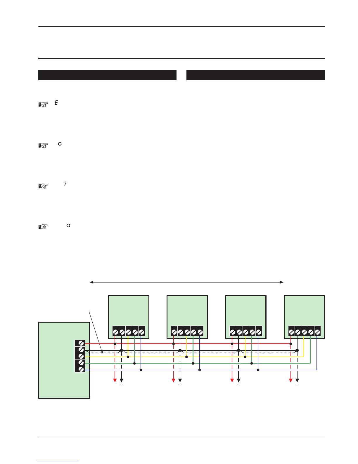
Remote/LEC Network Wiring
The Remote Network connections are used for
connecting either remote keypads or LECs. Each
device has 5 connection terminals and therefore
a 6 core cable is required for interconnection. It is
recommended that the spare core is doubled up
with the [B] connection as this will help reduce
voltage drop on long cable runs.
Devices can be individually connected back to
the control panel (star connection) or looped
together (daisy-chain connection). Which ever
method of connection is used the distance to the
furthest device from the control panel must not
exceed 100 metres.
Power for detectors are provided by the [A] and [B]
terminals (see figure 2).
7
TS590 Installation Manual System Installation
Remote
Network
Spare Core
Control Panel
Power for
detectors
Power for
detectors
Power for
detectors
Power for
detectors
I/D=2I/D=1 I/D=3 I/D=4
Remote
Keypad
or LEC
ABCDE
Remote
Keypad
or LEC
ABCDE
Remote
Keypad
or LEC
ABCDE
Remote
Keypad
or LEC
ABCDE
A
B
C
D
E
100m (Max.)
+ + + +
Figure 2. TS590 Remote Network Wiring
Page 8

Control Panel Installation
Proceed as follows:
1. Open the control panel by removing two
screws from the frontcover. Removethe cover
and disconnect the earth bonding cable from
the spade connection near the transformer.
2. Note the position of the cable entries as
follows:
(a) Ten 20mm cable entries for detection,
alarm and remote keypad cables.
(b) A 20mm cable entry for mains (230V)
below the mains input terminal block.
+
The mains cable must enter the control
panel through its own cable entry and
must not be mixed with other cables.
3. Hold the controlpanel back box in therequired
position and mark the centre of the middle
fixing position. Remove the back box, drill and
plug the hole.
4. Screw a No 10 screw into the plugged hole.
Reposition the back box and mark the
remaining two securing holes. Remove the
back box, drill and plug the holes.
5. Reposition the back box and pass all cables
into the base via the appropriate cable
entries, remembering to fit grommets where
necessary.
6. Secure theback boxusing notless than30mm
x No 10 screws through the three securing
holes.
7. If required install and connect the following:
(a) Stand alone digicom or RedCARE STU.
(b) Printer type DATAC or serial RS232 via a
printer adapter (MPA/DCI).
(c) Relay module type RM.3A.
+
When replacing the cover, always
ensure that the earth bonding lead is
connected to the spade connection on
the transformer.
8
System Installation TS590 Installation Manual
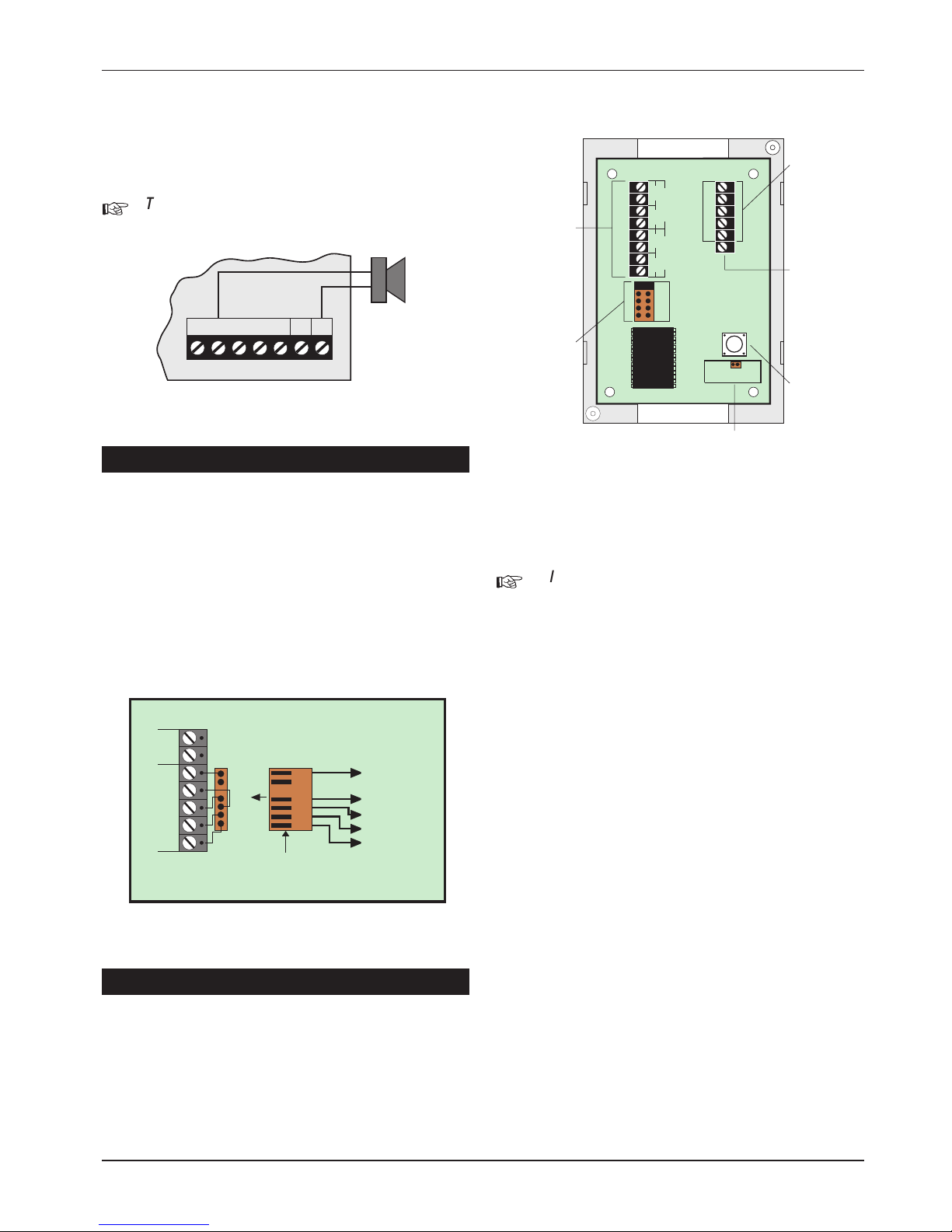
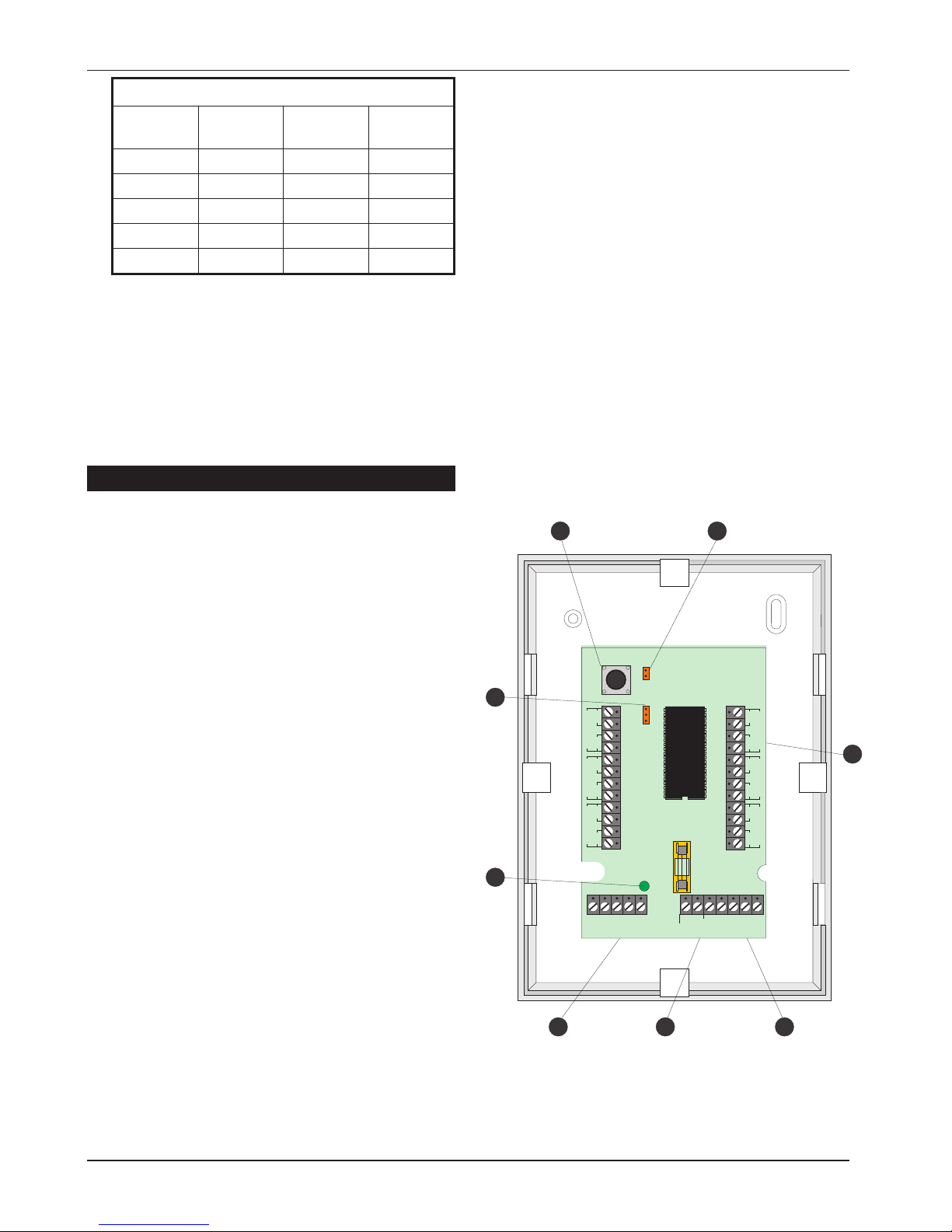
Figure 3. TS590 Control Panel Layout
Page 9
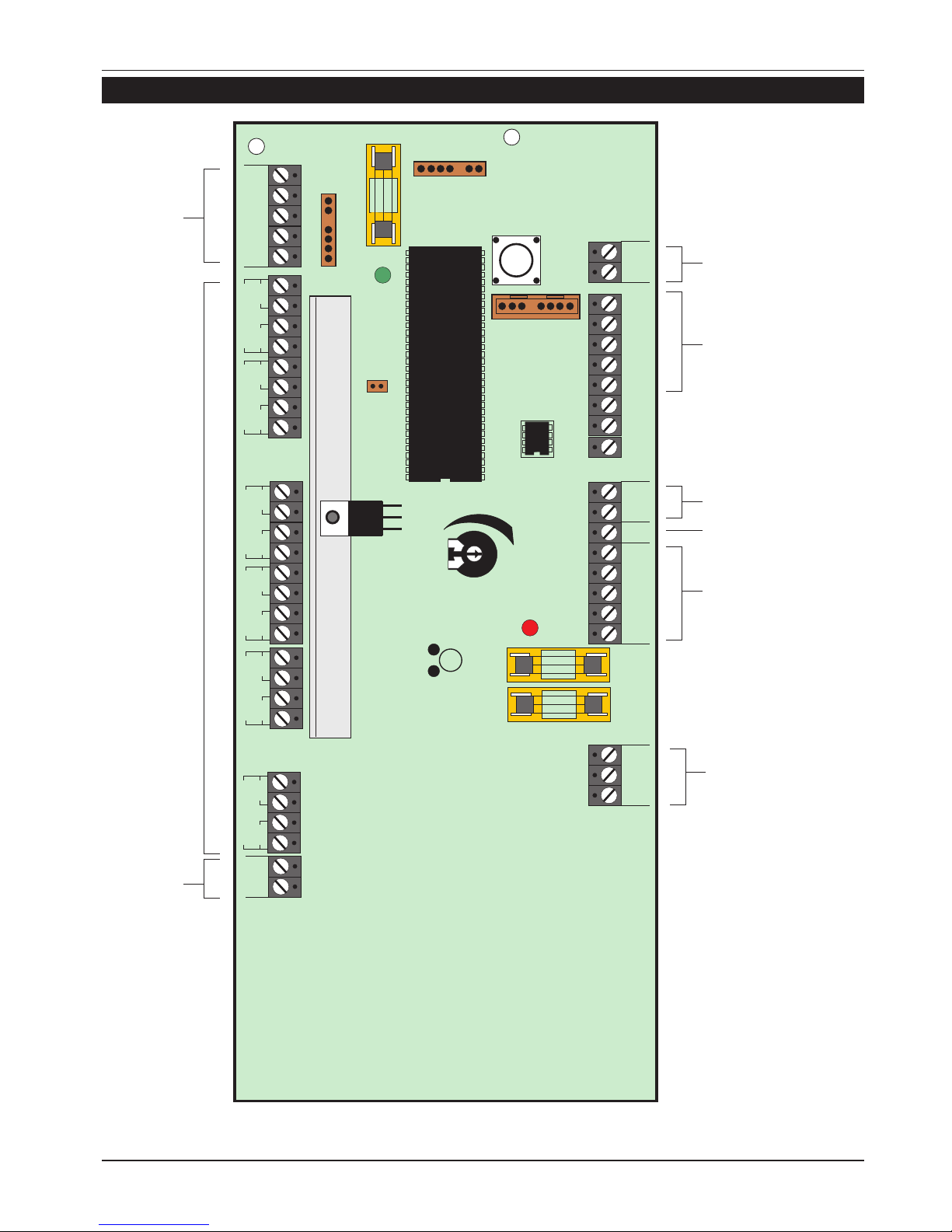
Control Panel PCB Layout
9
TS590 Installation Manual System Installation
PRINTER
REMOTE KEYPAD
JP3
DIGI-MODEM
FACTORY
RESET
Auxiliary 12V (SELV)
Remote
keypad
Network
connections
(SELV)
Programmable
Detection
Circuits 1 - 6
(SELV)
Aux 12V
Digicom Outputs
Programmable @ 100mA
(SELV)
Auxiliary Tamper (SELV)
Extension loudspeaker
(SELV)
External sounder
connections
(SELV)
21V A.C. from mains
transformer
(SELV)
Z1
Z2
Z3
Z4
Z5
Z6
AUX
0V 12V
T1
T2
T3
T4
T5
T6
CIRCUIT 1
CIRCUIT 2
CIRCUIT 3
CIRCUIT 4
CIRCUIT 5
CIRCUIT 6
JP5
SPEAKER
VOLUME
V
NVM
AUX
BELL
1 AMP
1 AMP
BATT
FAULT
POWER
ON
TRG
-
STB
-
TR- H/O
-
H/O
+
SPK
+
AUX
TAMP
LINE
FLT
+
REM
RESET
-
1234
DIGITAL COMMUNICATOR
5
AUX
A
REMOTE NETWORK
BCDE
0V 12V
A.C.A.C.
1 AMP
JP1
JP2
ENGINEERS REMOTE
U3
+
DC
PWR
FS1
FS2
VR2
FS3
LED1
LED2
Figure 4. TS590 Main PCB
Page 10

Connection Terminals & Indicators
Connection terminals on the TS590 are described
as ether “Safety Extra-Low Voltage”(SELV) circuits or
“Telecommunication Network Voltages” (TNV)
circuits. Figure 4 shows the two types of circuits.
JP1 PRINTER
This 6-pin plug is used for connecting to
either a CPA6.P printer or a standard RS232
printer via the MPA/DCI printer adapter.
JP2 ENGINEERS REMOTE
An Engineers remote keypad may be
temporarily connected to this 6-pin plug to
allow programming and testing to be
carried out at the control panel.
JP3 DIGI-MODEM
The DCI lead connects to this plug when
using the Lineload software via a P.C. for
direct communication with the control
panel. A DC54, DC58 or DC58M can alsobe
connected to this plug.
JP5 FACTORY RESET
If these pins are shorted during power-up all
system parameters are reset to their factory
default settings. If the engineer’s passcode is
lost or forgotten it can be reset to 1234
without losing any other program data. The
procedure for resetting the engineer’s
passcode is described on page 45.
VR2 SPEAKER VOLUME
When an extension loudspeaker is
connected to the control panel terminals
the volume of the advisory tones may be
adjusted using this control.
+
Alarm tones are always at full volume.
U3 NVM
A removable nonvolatile memory (NVM)
device that stores all system program
parameters and the 700 log events.
LED1 BATT FAULT
If the system battery is incorrectly
connected to the control panel or the
battery voltage is below 4 Volts, then the
“BATT FAULT” LED will light. The fault LED will
only extinguish when the battery has been
correctly connected or replaced, as
appropriate.
LED2 POWER ON
This LED indicates that the system power
(mains or battery) is healthy.
V SYSTEM CURRENT CONSUMPTION
The system current consumption may be
calculated by measuring the Voltage
across this test point on the main PCB. Using
a Voltmeter set to a low Voltage range
measure the Voltage across the test point
and multiply the reading by 10 to give the
Total system current consumption i.e., a
reading of 70mV = 700mA.
FS1 BELL
This 1 Amp fuse protects the supply to the
external sounder/bell. The fuse is in-line with
the [H/O+] terminal connection.
FS2 AUXILIARY
This 1 Amp fuse protects the auxiliary supply
output. The fuse is in-line with the [AUX. 12V]
terminal connections.
FS3 REMOTE KEYPAD
This 1 Amp fuse protects the supply to the
remote network. The fuseis in-linewith the [A]
terminal connection.
10
System Installation TS590 Installation Manual
Page 11

Mains Connection
The mains supply is connected to a 3 way “Euro
Type” fused terminal block, which is fitted with a
315mA fuse. All electrical connections should be
carried out by a qualified electrician and must
comply with the current IEE regulations.
+
To comply with European regulations the
supply should be fed from a readily
accessible disconnect device, e.g.
un-switched fused spur fitted.
+
When making mains connections it should
be ensured that if the cable slips in such a
way as to placea strain onthe conductors,
the protective earthing conductor will be
the last to take the strain.
Battery Connection
A 7Ah battery must be fitted to the system to allow
it to function during a mains fail condition. The
TS590 is equipped with a “Battery Protection”
circuit so that if a battery is accidentally reverse
connected or its voltage is below 4V, the “BATT
FAULT” LED lights. To clear the fault simply
reconnect or replace the battery as appropriate.
Remote Keypads
Two types of remote keypads can be used on the
system. Any combination of remote keypad can
be used on the same system, if desired.
LCD Remote Keypad
The LCD remote keypad has a 32 character
backlit Liquid Crystal Display (LCD).
NETLCD Remote Keypad
The NETLCD remote keypad has a 32 character
backlit Liquid Crystal Display (LCD), loudspeaker
outputs, two zone inputs and an internal sounder.
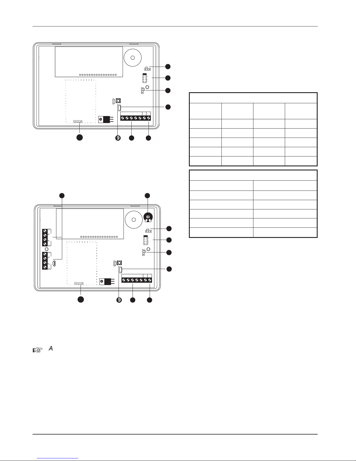
PCB Layouts & Connections
Detection Circuits.
NETLCD remote keypad has two
programmable detection circuits.
Loudspeaker Volume.
For adjusting the volume of a speaker wired
to the remote keypad (NETLCD only).
LED Mimic.
If this jumper link is set to the “enabled”
position, the red () LED on the keypad will
be “ON” when the keypad output is active.
Remote I/D.
Used to select the remote keypads address.
(ENG = Engineer).
Ward Sounder Control.
If this jumper link is set to the “disabled”
position, the remote keypad sounder will
follow the control panel speaker output. If
this link is set to “enabled”, the remote
keypad sounder will only activate when the
panel speaker and the output on the
remote keypad are active at the same time.
Loudspeaker Output.
This terminal can be connected to a single
16 Ohm Loudspeaker (NETLCD only).
Network Connections & O/P.
Terminals A to E are used to connect the
remote keypad to the control panel
network. The O/P terminal is the
programmable output.
Tamper Switch.
Remote Keypad case tamper
ENT Key Disable.
If the “ENT” key is enabled the remote
keypad can be used to set/unset and
access all user menus. If the “ENT” key is
disabled the remote keypad can only be
used to set and unset the system.
11
TS590 Installation Manual System Installation
L
E
N
To transformer
FUSE 315mA
Figure 5. Mains Supply Connections
Page 12
Installation Procedure.
+
Always ensure that all power (mains and
battery) is removed before making any
connections to the remote keypad.
1. Separate the cover and base by using a
screwdriver to push 2 of the clips (top or
bottom) inward from the base indents, then lift
the cover assembly, noting thatthe PCB isfixed
to the under side of the cover.
2. Hold the base in position (keyhole to the top)
and mark the three securing holes, drill and
plug the wall as required. Pass all the cables
into the base via the cable entry points as
appropriate and secure the base to the wall.
3. Connect “Remote Network” and detection
circuit cables to the appropriate terminals.
4. Set the I/D selector jumper link to the required
position:
NETLCD, TS700 LEC and LEC6
I/D Selector Circuit A Circuit B
Panel
Output
107085
209106
311127
413148
ENG/NULL N/A N/A N/A
LCD Remote Keypad
I/D Selector Panel Output
15
26
37
48
ENG/NULL N/A
l
No two remote keypads or LECs should
have the same I/D.
l
If the I/D is set to “ENG” the remote keypad
will function as an Engineer’s keypad
allowing it to be plugged onto the control
panel so that system programming and
testing can be carried out, see Engineer’s
Keypad.
5. Set the “ENT KEY DISABLE” jumper link to the
required position.
6. Set the“WARD SOUNDER CONTROL” jumper link
to the required position.
7. Finally clip the remote keypad cover onto the
base being careful not to trap any cables or to
obstruct the tamper switch.
12
System Installation TS590 Installation Manual
I/D
Selector
REMOTE
I/D
LED MIMIC
1
2
3
4
ENG
WARD SOUNDER
CONTROL
ABCDE
SPK
+
3
5
4
6
7
Display Module
O/P
-
889 8
10
Figure 6. LCD Remote Keypad PCB Layout
I/D
Selector
REMOTE
I/D
LED MIMIC
1
2
3
4
ENG
CCT B
ZB
TB
CCT A
ZA
TA
WARD SOUNDER
CONTROL
ABCDE
SPK
+
1 2
3
5
4
6
7
Display Module
O/P
-
889 8
10
Figure 7. NETLCD PCB Layout
Page 13
Keypad Loudspeaker Connections
A single 16 Ohm loudspeaker may be wired to the
keypad if required. This loudspeaker will follow the
existing keypad sounder and its volume level can
be adjusted by the speaker volume pot (VR1).
+
The speaker output and volume pot are
only available on the NETLCD keypad.
Engineer’s Keypad
Normally all system programming will be carried
out from one of the installed remote keypads,
however sometimes it may be more convenient
to program the system at the control panel. This
can be achieved by using an “Engineers Keypad”
which is temporarily plugged on to the control
panel (JP2). To converta standardremote keypad
to an “Engineers Keypad” an Engineer’s interface
lead is required which can be obtained from your
supplier (P/No. NETEKI).
TS700 LEC Installation
The TS700 LEC (Local Expansion Card) is
connected to the “RemoteNetwork” and provides
two additional programmable detection circuits
and a programmable output. The “Remote
Network” may have up to three LECs connected,
as the system will always require at least one
remote keypad.
+
Always ensure that all power (mains and
battery) is removed before making any
connections to the LEC..
1. Remove the coverfrom the baseand carefully
remove the PCB.
2. If theLEC isbeing fittedinside thecontrol panel
you may remove the LEC PCB from its base
and secure it to the base of the control panel
using self adhesive feet. If required,the tamper
switch may also be disabled by fitting the
jumper link across JP2, see Figure 10.
3. If the LEC is being fitted outside the control
panel, hold the base in position and mark the
two securing holes. Drill and plug the wall, then
pass all cables into the base via the cable
entry points. Secure the base to the wall using
the appropriate fixing screws.
4. Connect “Remote Network” cables and
detection circuit cables to the appropriate
terminals, see Figure 10
5. Set the I/D selector jumper link to the required
position:
13
TS590 Installation Manual System Installation
1x16Ohm
Loudspeaker
ABCDE
SPK
+
O/P
-
Figure 8. NETLCD Speaker Connections
Control Panel
To TS900
Remote
Keypad
A (Red)
A
AUX
12V
0V
ENGINEERS REMOTE
JP2
C (Yellow)
B
B (Black)
C
D (White)
D
E (Blue)
E
7 Way 0.1" Molex
connector
Figure 9. Engineer’s Keypad Connection
Network
connections
Programmable
output
switched -ve
@100mA
Tamper switch
Fit jumper-link to
disable tamper switch
CABLE ENTRY
CABLE ENTRY
Programmable
detection circuits
I/D selector
CCT B
ED
C
B
LEC I/D
A
12 34
NULL
JP2
TAMPER= JP2 NOT FITTED
NO TAMPER= JP2 FITTED
CCT A
TA
TB
ZA
ZB
O/P
Figure 10. TS700.LEC Layout
Page 14
TS590
I/D Selector Circuit A Circuit B
Panel
Output
107085
209106
311127
413148
ENG/NULL N/A N/A N/A
l
No two LECs or remote keypads should
have the same I/D.
l
DO NOT set the I/D selector to the “NULL”
position.
6. Finally clip the LEC cover onto the base being
careful not to trapany cablesor toobstruct the
tamper switch.
LEC 6
PCB Layouts & Connections
Tamper Switch
Case tamper protection.
Tamper disable (JP2)
Fit jumper link acrossto disablecase tamper
protection.
Detection Circuits.
Each 6 Zone LEC has six programmable
detection circuits. For details on
programming these circuits, refer to the
relevant panel Installation Manual.
Programmable Outputs.
The 6 zone LEC has three programmable
outputs. When JP1 is set to the(2 - 4) position
all three outputs are enabled. When JP1 is
set to the(3 - 4) position only outputs B and C
are enabled. Each output is a switched -ve
@ 100mA. For details on programming
these outputs, refer to the relevant panel
Installation Manual.
Auxiliary 12V Output
A set of auxiliary 12V outputs for powering
detection devices etc. This output is
protected by the AUX 12V fuse (500mA).
Remote Network Connections
Terminals A to E are used to connect the 6
zone LEC to the control panel network.
Power LED
This LED indicates that mains power is
present at the control panel. When mains
power is removed and the system is running
on its standby battery, this LED will flash.
LEC ID (JP1)
When set to the 2-4 position the 6 zone LEC
will report to control panel as LEC’s 2, 3 and
4. In this position zones A-F and outputs A-C
are enabled. This position will typically be
used when the system only has one remote
keypad fitted.
When set to the 3-4 position the 6 zone LEC
will report to control panel as LEC’s 3 and 4.
In this position zones C-F and outputs B and
C are enabled. This position will typically be
used when the system has two remote
keypads fitted.
14
System Installation TS590 Installation Manual
ABCDE
AUX 12V
OUTPUTS
AUX 12V
500mA
LEC I/D
JP1
2-4
3-4
ZF
ZE
ZD
CIRCUIT F
CIRCUIT E
CIRCUIT D
TF
TE
TD
ZA
ZC
ZB
CIRCUIT A
CIRCUIT C
CIRCUIT B
TA
TC
TB
JP2 FITTED = NO TAMPER
REMOTE NETWORK
+ + A- B- C---
1 2
3
456
7
8
Figure 11. 6 Zone LEC PCB Layout
Page 15
LEC 6 Installation
Always ensure that all power (mains and battery) is
removed before makingany connections to the 6
Zone LEC.
1. Separate the cover and base by using a flat
blade screwdriver to push 2 of the clips (left or
right) inwards from the base indents. Then
gently prise the two halves apart and lift the
cover away from the base.
2. Hold the base in the required position and
mark the appropriate securing holes, drill and
plug the wall as required. Pass all cables into
the base via the cable entry points as
appropriate and secure the base to the wall.
3. Connect the “Remote Network” cables to the
appropriate terminals A-E.
4. Connect detection circuit cables to the
appropriate terminals.
5. Set the LEC I/D jumper link to the required
position, remembering that no two devices
should have the same I/D.
6. Clip the cover onto the base being careful not
to trap any cables or to obstruct the tamper
switch.
7. Re-apply the power and refer to “Program
Circuits” & “Panel Outputs” within the relevant
Installation and Programming Manuals.
LEC6 Connections
The 6 zone LEC requires a 6 core cable for
connection to the control panel and can be
connected in a “Star or Daisy-chain”
configuration. The distance to the furthest device
from the control panel must not exceed 100
metres. Power for detectors is provided via the
auxiliary 12v terminals. The spare core can be
used to double up the B connection to help
reduce voltage drop to the network.
The 6 zone LEC has a jumper which allows it to be
configured for 6 zone expansion or 4 zone
expansion. The table below shows the circuits that
are allocated for both jumper settings.
JP1 = 2-4 (A-F) JP1 = 3-4 (C-F)
Circuits 9 - 14 Circuits 11 - 14
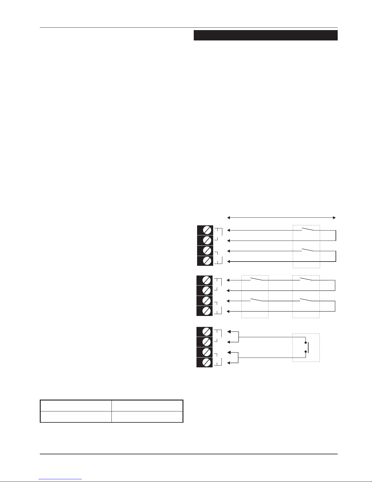
Wiring Detection Circuits
All detection circuitsmay bewired as “End Of Line”
(EOL) or “Double Pole” (DP). Both methods can be
used on the same equipment.
Double Pole
The DP method requires the following:
l
The detector alarm and tamper contacts are
connected to the zone and tamper terminals
respectively.
l
The combined alarm and tamper loop
resistance must be less than 100 Ohms.
l
The maximum number of detection devices
allowed in a circuit is ten.
l
Normally open devices such as pressure pads
and exit terminator buttons are connected
between the zone and tamper terminals.
l
If the detection circuit is not used links can be
fitted across the zone and tamper loops or
programmed as Not Used.
15
TS590 Installation Manual System Installation
Alarm
Tamper
CIRCUIT A
ZA
TA
CIRCUIT A
ZA
TA
CIRCUIT A
ZA
TA
Alarm
Tamper
Max. 10 devices per circuit
Wiring N.O. devices (Exit Terminators)
Alarm
Tamper
500 metres or 100 Ohms
Figure 12. Double Pole Wiring
Page 16
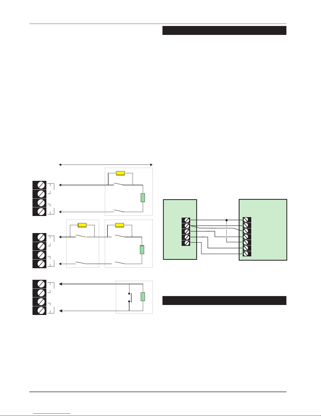
End Of Line
The EOL method requires the following:
l
The detector alarm contacts must have a 4K7
shunt resistor fitted.
l
A 2K2 End ofLine (EOL)resistor mustbe fitted at
the point in the circuit furthest from the control
panel.
l
Loop resistance with the EOL resistor shorted
must be less than 100 Ohms.
l
The maximum number of detection devices
allowed in a circuit is ten.
l
Normally open devices such as pressure pads
and exit terminator buttons are connected
across outer terminals
l
If the detection circuit is not used links can be
fitted across the zone and tamper loops or
programmed as Not Used.
External Sounder Connections
The following terminals have been provided to
allow connections to an external sounder:
H/O - This is used to provide a permanent -ve
hold off to external sounders, strobes etc.
H/O + This is used to provide a permanent +ve
hold off to external sounders, strobes etc.
It is protected by a 1 Amp fuse (Bell12V).
TR - This is the negative tamper return
connection from the siren or bell.
STB - This is the strobe output which will switch to
0V on alarm and is rated at 500mA.
Connect the other side of the strobe to
the H/O +.
TRG - This is the bell trigger output which can be
programmed for SAB or SCB operation, as
follows:
SAB: TRG - will switch to 0V on alarm and
will provide a maximum of 500mA.
SCB: TRG - will provide a negative hold
off (500mA), which is removed on alarm.
Auxiliary Tamper
These two terminals provide tamper protection to
auxiliary devices such as power supplies,
extension loudspeakers etc. If they are not used
they must be linked out.
16
System Installation TS590 Installation Manual
500 metres or 100 Ohms
Alarm
Alarm
Tamper
Max. 10 devices per circuit
Wiring N.O. devices (Exit Terminators)
Tamper
4K7 = Yellow, Violet, Red
2K2 = Red, Red, Red
Alarm
Tamper
4K7
4K7
4K7
2K2
2K2
2K2
CIRCUIT B
ZB
TB
CIRCUIT B
ZB
TB
CIRCUIT B
ZB
TB
Figure 13. End of Line Wiring
Typical
External Sounder
Control
Panel
H/O +
12V +
H/O -
0V
Tamper In
TR -
STB -
Tamper Out
TRG -
Strobe +ve
Strobe -ve
Trigger -ve
Figure 14. External Sounder Connections
Page 17

Extension Loudspeakers
Up to two extension loudspeakers can be
connected across the [SPK+] and [H/O-] terminals
on the control panel PCB. The volume for the
loudspeaker is controlled by VR1 “Speaker
Volume”.
Digicom/RedCARE Installation
A stand alone digital communicator, RedCARE
STU or Paknetinterface card can be connectedto
the control panel using the following connections:
Digicom Outputs 1 to 5
These are the programmable digicom output
connections. They are normally at +12V and
switch to 0V when active. The outputs can be
inverted so that they switch from 0V to +12V when
active, see System Configuration on page 30.
Each output will source 5mAin the +12Vcondition
and sink 100mA in the 0V condition.
+DC POWER
This provides the +12V power to the digicom. This
output is un-fused and therefore should only be
used if the digicom is fitted inside the control
panel. The 0V supply for the digicom/STU can be
picked up from any of the auxiliary 0V terminals.
LINE FLT
When this input is switched to +12V, a “Line Fault”
condition is generated. A “Line Fault” condition In
the unset mode will cause a “Chime” type tone to
be generated every minute, which can be
silenced by entering any valid passcode. A “Line
Fault” condition In the set mode will cancel the
“Bell Delay”.
REM RESET
If the system is programmed for “Engineer Reset”,
then after a full alarm the system will require
resetting, normally this is done by the engineer or
coded remote reset. Applying a -ve to this input
terminal will cause the system to reset after a full
alarm. This input could be connected to the
“Control” output on a RedCARE STU so that the
Alarm Receiving Centre can poll the STU and thus
reset the panel.
17
TS590 Installation Manual System Installation
1 x 16 Ohm Loudspeaker
2 x 16 Ohm Loudspeakers
SPK+
H/O -
SPK+
H/O -
Figure 15. Loudspeaker Connections
Control
Panel
3GSTU
1
1
+DC POWER
Program
As:-
Active Omit (056)
Alarm (005)
PA (006)
Alarm Conf (011)
LINE FLT
AUX 0V
2
2
3
3
4
4
5
TB1
Channel Inputs are
Programmed as
Positive Removed
TB2
TB3
TB4
Control
Line
Fault
RPS
5
67
0V
NO
NO
NO
NC
NC
NC
8
C
C
C
A+
A+
A+
A+
V+
REM RESET
Note: the default for
Output 1 is Fire (007)
Open (036)
Figure 16. 3GSTU RedCARE Connections
Page 18

DC54 & DC58M Installation
A plug-on digital communicator DC54, DC58 or
DC58M may be fitted inside the control panel to
allow alarm status information to be transferred to
a dedicated central station. The unit should be
fitted in accordance with the installation
instructions supplied with it and connected to the
control panel plug DIGI-MODEM (JP3) using the
lead provided with the unit. The NVM within the
communicator will need to be programmed
using an engineer’s keypad or PP5.
Connecting a Printer
The TS590 supports two type of printers, the CPA6
printer (no longer available) and any standard
RS232 printer. When using an RS232 printer a
DCI/MPA printer adaptor will be required. Menvier
Security supply aDATAC printer kit which consistsof
a portable RS232 printer, charger unit and DCI
adapter.
Using the DATAC / RS232 Printer
1. Plug the DCI/MPA on to the PRINTER plug (JP1)
on the main control panel PCB.
2. Plug the other end of the DCI/MPA into the
DATAC or RS232 printer.
3. In order for the printer to work correctly ensure
that the printer is set to the following:
Baud rate = 4800
Parity = None
Start bits = 1
Stop bits = 2
Data bits = 8
DTR = Normal
4. When setup correctly the system program
details and event log can be printed.
5. When finished unplug the MPA/DCI. If the
printer is left connected events will be printed
as and when they occur.
18
System Installation TS590 Installation Manual
Connect to JP3
DIGI-MODEM
Plug-on digicom / digi-modem
A
B
BC
B.T. master jack ( Type NTE5
user accessible connections )
A(5) = White / Blue ring
BC(3) = Orange / White ring
B(2) = Blue / White ring
Telephone cable
(Type 1/0.5mm CW1308)
6
5
4
3
2
1
Figure 17. DC54/DC58 Connections
MPA
or DCI
DATAC or RS232 printer
RS232 Data
Connect to JP1
PRINTER
1
Figure 18. Printer Connections
Page 19

Pre Power-Up Checks
Once the system is installed, but prior to
powering-up, give the system one final check to
ensure that:
1. The wiring conforms to the requirements
detailed in this manual and that all
interconnections are correct (A to A, B to B
etc.).
2. All system cables are kept clear of mains
supply cables, telephone cables and R.F.
cables. It is recommended that cable ties be
used to keep cables separated.
3. Verify that maximum cable lengths and
resistance's are not exceeded.
4. Mains power supply cables to the system are
connected to an un-switched fused spur.
5. Grommets are used where cablesenter metal
housings to ensure that insulation is not
compromised.
Initial Power-Up
To power the system for the first time:
1. Place a small screwdriver blade between the
pins on the control panel PCB, marked
“FACTORY RESET”. This will ensure the factory
default parameters are set, see page 20.
2. Switch on the 240V mains supply and remove
the screwdriver blade.
3. Check thatthe power LED on the control panel
PCB is illuminated.
4. Check that the remote keypads display “Panel
Lid tamper”. The remote keypad sounders and
extension loudspeakers will operate.
5. Enter the engineers passcode (default 1234)
to silence the sounders.
6. Connect the standby battery.
Power-Up Checks
When the initial power-up checks have been
completed, check the following:
1. Switch off the 240V mainssupply and measure
the DC voltage at each remote keypad and
ensure the voltage is greater than 11V whilst
the system is powered from its standby battery.
2. Switch on the 240V mainssupply and measure
the DC voltage between the mains earth
connection and AUX. +12V. Then measurethe
DC voltage between the mains earth
connection and AUX. 0V. In both cases the
measurement should be 1V or less. If the
voltage is greater than 1V, the system has an
“Earth Fault” and allcables should bechecked
for isolation to Earth
3. Using a voltmeter measure the DC voltage
across the control panelPCB testpoints (V)and
calculate the system current consumption
(see page 10). Ensure that the reading is not
greater than 1.0A.
4. Repeat test (3) with the system in an alarm
condition and ensure that the reading is not
greater than 1.0A.
19
TS590 Installation Manual System Installation
Page 20

NVM Defaults
20
System Installation TS590 Installation Manual
Section Option Default
User Codes
User 00 Engineer 1234
User 01 Master 5678
Keypad
Outputs
Keypad Outputs 1, 2,
3 & 4
Code Accepted
Digicom
Outputs
Digicom Output 1 Fire
Digicom Output 2 PA
Digicom Output 3 Alarm
Digicom Output 4 Set
Digicom Output 5 Second Alarm
Digicom
Channels
Digi Channel 1 Fire
Digi Channel 2 PA
Digi Channel 3 Alarm
Digi Channel 4 Set
Digi Channel 5 Second Alarm
Digi Channel 6, 7, 8 Always Off
System Timers
00: Abort Delay 180 seconds
01: No. Re-arms 003
02: Settle Time 007 seconds
03: Pset Com.Dly 000 seconds
04: Exit Time 030 seconds
05: Entry Time 015 seconds
06: Bell Dur. 020 minutes
07: Bell Delay 000 minutes
08: 2act. Time 008 seconds
09: Test Time 014 days
10: 2nd Entry 015 seconds
11: Part Set Entry 000 seconds
12: Monitor Dur. 000 seconds
13: Pset Bel.Dly 000 seconds
14: Courtesy Dur. 030 seconds
15: No. Rem. Reset 010
16: Modem Rings 000
17: P.I.D Alarms 005
18: AC Off Dly 000 minutes
19: Test Call 000 days
20: 2nd Alm Time 060 seconds
21: Line Flt Dly 000 minutes
System Timers
22-Service Time 000 months
23-Test Call At 003
Section Option Default
Setting Modes
Full Set Final Exit Setting
Part Set A Timed Exit
Part Set B Timed Exit
Part Set C Timed Exit
Rem Reset
Algorithm 004
Configuration
(see Note)
00: Bell is an SAB Yes
01: User 1 Limited No
02: Fire Signals All No
03: Silent 24hr Ccts No
04: Enable Duress No
05: Invert Abort O/P No
06: SET with LF Yes
07: User Reset Yes
08: Extended Format No
09: Hi-Sec Engineer No
10: Tamps User Reset Yes
11: Do Battery Test No
12: F.Exit is Night No
13: Use code+ Enter No
14: Show P.set disp. Yes
15: Dial Consec. Yes
16: SET with AC Off Yes
17: Loud ChimeTones No
18: Invert Output 1 No
19: Invert Digi O/Ps No
20: On-Line Key pad Yes
21: Restore P.I.D Yes
22: User Authorised No
23: Mimic Alrm & Flt. No
24: Monitor Off Hook No
25: Answer PhoneDef. No
29: Keypad PA Silent No
Modem
Options
Call Back No 1, 2 & 3 Blank
Modem Password Blank
Modem Site No. Blank
Note: Options 26, 27, and 28 are intentionally
missing. The plug-on didgi modem of the T590:
1. Always sends Open/Close signals.
2. Only sends 24hr/Auxilliary or Tamper signals
when the system is set or part set.
Page 21

Engineer’s Menu 1
Introduction
Engineers menu 1 is the first of two engineers
menus, which is selected when the engineer’s
passcode is entered. The engineer may leave
“Engineer menu 1" by pressing the [ESC] key. The
system will return to the unset condition but the
remote keypads will show ”Engineer-on-site". This
message will be cleared the next time a valid user
passcode is entered or by exiting the engineer's
mode via user menu 1.
Menu contents
Hot key Option Page
1
Program Panel Outputs 22
2
Program Digicom Outputs 22
3
Program Digicom Channels 22
4
Program Circuits & Attributes 25
5
Program System Timers 27
6
Program Setting Modes 29
7
System Printout 29
8
Remote Reset Number 30
9
Program Configuration 30
0
Go to User Menu 1 32
B
View Location Text 33
C
Relearn Hardware 34
+
Whilst Engineer’s mode is selected all
tampers are not monitored.
+
After performing a factory restart or on-site
restart the system will show “RELEARN
REQUIRED” (RESET CONFIG) when the
engineer exits from engineers mode. This
message is cleared by performing a
“Hardware Relearn”, see page 34.
21
TS590 Installation Manual Engineer’s Menu 1
Engineers menu 1
Select Option :-
PANEL IS IN
RECEPTION CLOSET
Panel output ?
Enter Number >-
Digi output ?
Enter Number >-
Digi channel ?
Enter Number >-
Program circuits
Enter CCT No.>--
System Timers
Enter Number >--
Setting Modes ?
Enter Group >-
System Print Out
Line Number 001
Remote Reset
Algorithm >004
Configuration
Enter Number
User menu 1
Select Option:-
1
2
3
4
5
6
7
8
9
0
ESC
1 2 3 4
Enter Engineer's
Passcode
B
C
Relearn Hardware
Engineers Menu 1
Page 22

Keypad Outputs [1.1]
Outputs 1-4 can be programmed to any of the
output types shown on pages 22 to 24.
Digicom Outputs [1.2]
The 5 digicom outputs on the control panel PCB
can be programmed to any of the output types
shown on pages 22 to 24. In addition, all outputs
can be inverted, see “Configuration option 19” on
page 31.
Digicom Channels [1.3]
The 8 plug-on digicom channels can be
programmed to any of the output types shown on
pages 22 to 24.
Programmable Output Types
No Type/Description
000 Bell On
Activates when the main Bell trigger is on and
deactivates at the end of the Bell Duration
time or when the alarm is cancelled by the
user.
001 Strobe On
Activates when the Strobe trigger is on, and
deactivates when the alarm is cancelled by
the user.
002 Switch 12V
Activates when the system is set and
deactivates when an alarm occurs or the
system is unset. This output is normally used for
latching detectors.
003 Detector Reset
Normally active at all times and deactivates
for 3 seconds when a valid passcode is
entered prior to setting the system. This output
is normally used for detector that required
power to be removed in order to reset them,
e.g., smoke detectors.
22
Engineer’s Menu 1 TS590 Installation Manual
Keypad Output ?
Enter Number > -
Keypad Output 1
is type > 004
Keypad Output 1
is type > 021
Enter new output type
Type No.
1
Enter output No. 1 - 4
e.g. 1
ENT
e.g. 021
Engineers menu 1
Select Options :-
LCD
Panel Outputs Flowchart
Digi Output ?
Enter Number > -
Digi Output 5
is type > 055
Digi Output 5
is type > 043
Enter new output type
Type No.
2
Enter output No. 1 - 5
e.g. 5
ENT
e.g. 043
Engineers menu 1
Select Options :-
LCD
Digi Outputs Flowchart
Digi Channel ?
Enter Number > -
Digi Channel 8
is type > 055
Digi Channel 8
is type > 043
Enter new output type
Type No.
3
Enter channel No. 1 - 8
e.g. 8
ENT
e.g. 055
Engineers menu 1
Select Options :-
LCD
Digi Channels Flowchart
Page 23

No Type/Description
004 Walk Test
Activates when the "Walk Test" option is
selected and deactivates when the "Walk Test"
option is finished.
005 Alarm
Activates when an intruder alarm is detected
and deactivates when the alarm is reset or
aborted.
006 P.A.
Activates when a PA alarm is detected and
deactivates when the alarm is reset.
007 Fire
Activates when a Fire alarm is detected and
deactivates when the alarm is reset.
008 System Set
Activates when any ward is set and
deactivates when the system is fully unset.
009 Code Accepted
Activates for 5 seconds following entry of any
valid passcode.
010 24 Hour
Activates when a 24Hr alarm is detected and
deactivates when the alarm is reset.
011 Second Alarm
Activates when adifferent detectorcauses an
alarm and remains active for the duration of
the "2nd Alarm Time". This output is normally
used as an ALARM CONFIRMATION signal.
012 Courtesy Light
Activates during entry and when any remote
keypad is used. The duration of this output is
controlled by the setting of the "COURTESY
DUR" timer.
013 Engineer On Site
Activates when the engineer’s passcode is
entered and deactivates when a user
passcode is entered.
014 Circuits Omitted
Activates when any circuit is omitted and
deactivates when all circuits are reinstated.
015 Auxiliary
Activates when an Auxiliary alarm is detected
and deactivates when the alarm is reset.
016 Part Set C Selected
Activates when "Part Set C" is selected.
Deactivates when the system is unset.
No Type/Description
017 Part Set B Selected
Activates when "Part Set B" is selected.
Deactivates when the system is unset.
018 Part Set A Selected
Activates when "Part Set A" is selected.
Deactivates when the system is unset.
019 Full Set Selected
Activates when "Full Set" is selected.
Deactivates when the system is unset.
020 Tamper Fault
Activates when a Tamper alarm is detected
and deactivates when the alarm is reset.
021 Line Fault
Activates when a telephone line fault is
detected and deactivates when the fault is
cleared.
022 Mains Off
Activates when mains power is removed and
deactivates when the mains power is restored.
023 Exit / Entry
Activates when the panel is in the exit or entry
mode.
024 Test Fail
Activates when a circuit fails test, deactivates
when reset by the engineer.
025 First Knock
Activates when a double knock circuit is
activated for the first time. Deactivates when
the circuit is activated for the second time or
when the system is reset.
026 Comms Failed
Activates for 5 seconds when the plug-on
digicom fails to communicate.
027 Comms Success
Activates for 5 seconds when the plug-on
digicom communicates successfully.
028 Comms Active
Activates when the plug-on digicom is active
and deactivates when the plug-on digicom is
inactive.
029 2nd Entry
Activates when the second entry timer is
started and deactivates when the second
entry timer expires.
030 Entry
Activates when the panel is in the entry mode.
031 Exit
Activates when the panel is in the exit mode.
23
TS590 Installation Manual Engineer’s Menu 1
Page 24

No Type/Description
032 Duress Alarm
Activates when a duress passcode is entered
and deactivates when the duress alarm is
reset.
033 System Part Set
Activates when the system is part set and
deactivates when the system is fully set or
unset.
034 Battery Fault
Activates when a battery fault occurs and
deactivates when the battery fault is cleared.
035 Set Fail
Activates when the system fails to set and
deactivates when the set fail condition is reset
by the user.
036 System Open
Activates when the system is unset,,
deactivates when the system is fully set or
part-set.
037 New Alarm
Activates for 2 seconds when any circuit
causes a new alarm condition.
038 24hr Circuits Omitted
Activates when one or more 24 Hour circuits
are omitted.
039 Modem Lockout
Activates when the modem is locked-out (four
failed attempts). Deactivates when a master
user passcode is entered or after 4 hours.
040 Chime Mimic
Activates for 2 seconds when a circuit that is
programmed as "chime" is activated.
041 Shunt Group Active
Activates when the shuntcode hasbeen used
to shunt a group of circuits. Deactivates when
the shunt code is used again to re-instate the
circuits.
042 Timed Output
Activates when a "Monitored" circuit is
triggered and remains active for the duration
of the "Monitor Delay" see System Timers.
043 Abort
Activates for 5 seconds after an alarm is
aborted by the user. The period in which the
alarm may be aborted is set by the "Abort
Delay" see System Timers.
No Type/Description
044 General Fault
Activates during battery fault or when the
system is prevented from being set.
Deactivates when all faults are cleared.
045 Battery Test
Activates for 1 minute on the hour every hour.
This output is used to test the battery in remote
PSU’s using a 519FM monitor PCB).
046 Service Call
Activates when the system is on-line with a
remote PC and Lineload software.
047 System Full Set
Activates when all areas within the system are
set and deactivates when any area is unset.
050 PC Output 1
This output type is switched on and off via the
PC and Lineload software.
051 PC Output 2
This output type is switched on and off via the
PC and Lineload software.
052 Sounder Control
Normally used as the 0V connection for an
extension loudspeaker so that only system
alarm tones are generated. Only suitable for
Panel Outputs 1 and 2.
054 Call Engineer
Activates when the system requires an
"Engineer Reset", deactivates when the
system is reset by the engineer or "Remote
Reset".
055 Always Off
Never activates.
100 - 113 Circuit Mimic
Will mimic (active when circuit is active) circuits
01 to 14 respectively.
200 - 213 Circuit Alarms
Active when a circuit causes an alarm, or is
activated during a walk test, for circuits 01 to
14 respectively.
Following a wallk test, the operator can
confirm the operation of all the appropriate
circuits at a mimic panel. The control unit
clears these indications when the operator
enters a valid passcode.
24
Engineer’s Menu 1 TS590 Installation Manual
Page 25

Program Circuits [1.4]
The TS590 can monitor up to 14 detection circuits.
Each circuit must be programmed in order for the
system to respond correctly.
Circuit Types
The circuit type defines how the circuit will respond
when it is triggered. The following circuit types are
available:
0 Not Used
A circuit that will never generate any alarm.
1 Night
A circuit that will generatea full alarmwhen the
system is set.
2 24hr
A circuit which is monitored at all times. When
triggered in the unsetcondition a localalarm is
generated and when triggered in the set
condition a full alarm is generated.
3 PA Silent
A circuit which is monitored at all times. When
triggered it will activate any outputs that are
programmed as P.A.
4 PA Audible
A circuit which is monitored at all times. When
triggered it will activate any outputs that are
programmed as P.A. and generate a full
alarm condition.
5 Fire
A circuit that is normallyconnected to asmoke
detector. When triggered it will generate a fire
tone on the internal sounders, the external
sounders are pulsed for the bell duration and
any outputs programmed as fire will be
activated.
6 Auxiliary
A circuit which is monitored at all times. When
triggered it will activate any outputs
programmed as Auxiliary.
7 Final Exit
This must be the first detector or door contact
that is triggered when entering the protected
area. When the setting mode for the system is
programmed for Final Exit setting, opening
and closing of this circuit during the exit
procedure will cause the system to set. Once
set, activation of this circuit will start the entry
timer.
8 Exit Terminator
A circuit that is normally connected to a push
button outside the protected premises, which
can be used to finally set the system or area.
9 Keyswitch
(Also includes Lockset.) A circuit that may be
connected to a keyswitch to allow setting
and/or part-setting of the system.
The Keyswitch circuit has two groups of
attributes. The first group of attributes control
the wards that are set/unset when the circuit is
switched between “Healthy” and “Active”. The
second group of attributes selects the type of
Keyswitch (Momentary or Latched) or selects
the Lockswitch zone type.
When programming the Keyswitch circuit the
eight standard attributes are not available,
instead the attributes are used to select the
Keyswitch operation as follows:
[1] Full Set Group - “Healthy” to “Active”.
[2] Code Set Group A - “Healthy” to “Active”.
[3] Code Set Group B - “Healthy” to “Active”.
[4] Code Set Group C - “Healthy” to “Active”.
[5] Lockset - See Lockset Exit Mode.
[6] Momentary - Use for Momentary type
keyswitches. De-select for Latched
keyswitches.
[7] Inverted - Inverts the operation of the
keyswitch.
If the “Keyswitch” is not assigned to anyof the
above options, the circuit becomes a
“Monitored” circuit. A “Monitored” circuit is
monitored at all times. When triggered it will
activate any outputs that are programmed
as Timed Outputs and log the event.
Circuit Attributes
Each circuit type can have one or more attributes
assigned to it to alter its operation. The following
circuit attributes can be programmed:
1 Access
Circuits programmed with this attribute are
automatically isolated during the entry
procedure to allow a “walk through” route for
the user to access the remote keypad. The
“Access” attribute can only be assigned to
Night and Final Exit circuit types.
25
TS590 Installation Manual Engineer’s Menu 1
Page 26

2 Double Knock
Circuits programmed with this attribute will only
cause an alarm condition if:
a) The circuit is activated twice within the
Double Knock window (this time may be set in
the System Timers menu).
b) The circuit remains active for the whole
duration of the Double Knock window. The
“Double Knock” attributecan onlybe assigned
to Night, 24hr, PA and Auxiliary circuit types.
3 Test
Circuits with this attribute will be disabled from
the system for the period set by the “Test Time”
(see System Timers). If the circuit is activated
during this period the activation will be logged
and the user is informed of the circuit failure
when trying to set the system. The test fail
message may only be cleared with the
Engineers passcode. If at the end of the test
period no activations have occurred the
circuit is automatically removed from test and
behaves as normal. The test period is initiated
by entering the Engineers passcode. The “Test”
attribute can only be assigned to Night, 24hr,
PA Silent, PA Audible, Fire, Auxiliary, and circuit
types.
4 Omittable
Circuits with this attribute are allowed to be
omitted by the user when setting the system.
The “Omit” attribute can only be assigned to
Night, 24hr, and Auxiliary circuit types.
5 Reset
This attribute is normally assigned to a circuit
that is connected to a vibration or smoke
detector, so that during the “Detector Reset”
period the circuit is not monitored. The “Reset”
attribute can only be assigned to Night, 24hr,
Fire and Auxiliary circuit types.
6 Monitored
Circuits with this attribute will activate the
"Timed Output" when triggered. The
“Monitored” attribute can only be assigned to
Night, 24hr, Fire, Auxiliary and Final Exit circuit
types.
7 Entry
Circuits with this attribute will initiate the entry
procedure when the system is part-set and
respond as normal when full set. This attribute
must be assigned to all circuits that are
required to initiate the entry procedure in the
part-set condition. The “Entry” attribute can
only be assigned to Night, 24hr and Final Exit
circuit types. When assigned to a 24 Hour
circuit type, the circuit can be used to initiate
the entry procedure. Once the system is unset
the 24 hour will revert to normal operation.
8 Chime
Circuits with this attribute will cause the internal
sounders and remote keypad sounders to
generate a two tone “chime” sound if the
circuit is activated. The “chime” attribute may
only be assigned to Night, 24hr, Auxiliary, Final
Exit and Exit Terminator circuit types.
26
Engineer’s Menu 1 TS590 Installation Manual
Program circuits
Enter CCT No.>--
CCT 04 NIGHT
CCT 04 F.EXIT
>********
CCT 04 F.EXIT
>*******C
Enter circuit type:
= Not Used
= Night
= 24hr
= PA Silent
Circuit No.
Attributes
Circuit Type
4
0
1
2
3
ENT
Enter circuit No.
e.g. 04
= Fire
= Auxiliary
= Final Exit
5
6
7
ENT
e.g. 7 for Final Exit
Select attributes:
= ccessA
= KnockD
= estT
1
2
3
= esetR
= onitoredM
= ntryE
5
6
7
ENT
e.g. 8 for chime
= PA Audible
4
= mitO
4
= himeC
8
Engineers menu 1
Select Options :-
LCD
= Exit Terminator
= Key Point
8
9
Program Circuits Flowchart
Page 27

System Timers [1.5]
The system timers are as follows:
00 Abort Delay
This timer sets the period in which the alarm
signal may be aborted following an alarm
condition. When an alarm occurs, the “Abort
Output” (043) is only activated if the system is
unset within this period. If the system is unset
after this period the abort output is NOT
activated. The “Alarm” (005) output is also
restored when the abort output is activated.
This timer has a working range of 000-199
seconds. (Default: 180 Secs)
01 No. Re-arms
At the end of the bell duration time the system
re-arms all circuits that are healthy. Circuits that
are still in an alarm condition are isolated until
they change to a healthy condition. This
counter controls the number of times that a
"circuit" will re-arm before it is locked out of the
system. This counter has a working range of
000-199. (Default: 003)
02 Settle Time
When setting the system by “Final Exit” or “Exit
Terminator”, detectors that are on the exitroute
sometimes take 3-4 seconds to settle after
activation. The delay programmed inthis timer
is used to allow these detectors to settle before
the system or area is set. This timer has a
working range of 000-199 seconds. (Default:
007 Secs)
03 Pset Com. Dly
When the system is part-set the
communication of an alarm signal to the
central station can be delayed by the value
set in this timer. If the timer is set to 199 the
part-set communications are disabled. This
timer has a working range of 000-199 seconds.
(Default: 000 Secs)
04 Exit Time
This timer sets the delay between the user
initiating the exit procedure and the system (or
area) actually setting. If during the exit time an
“Exit Terminator” circuit is activated the exit
time is cancelled and the system sets
immediately. This timer has a working range of
000-199 seconds. (Default: 030 Secs)
05 Entry Time
When the system is set or part-set, and theentry
procedure is initiated, the entry timer starts to
count down. If a valid user passcode has not
been entered when the timer reaches zero,
the internal sounders are activated and the
“2nd Entry” timer is started. This timer has a
working range of 000-199 seconds. (Default:
015 Secs)
06 Bell Duration
This controls the duration of the external
bell/sounder. If the timer is set to 199 the bell
output is continuous. This timer has a working
range of 000-199 minutes. (Default: 020 Mins)
07 Bell Delay
This timer delays the activation of the external
bell/sounder and internal sounders. This timer
has a working rangeof 000-199minutes. Note:
Any alarm during the entry procedure will
cancel the bell delay. (Default: 000 Mins)
08 2 Act. Time (Double Knock)
This is the “DoubleKnock” timewindow inwhich
either two circuit activations must occur within
this time to generate an alarm condition. Or
the circuit must remain active for the whole
duration of this time to generate an alarm
condition. This will only apply to circuits with the
“Double Knock” attribute. This timer has a
working range of 000-199 seconds. (Default:
008 Secs)
09 Test Time
This timer varies the number of days that “Test”
attribute may be applied to a circuit. If the
timer is set to 000 then circuits will remain on
test until the “Test” attribute is removed. This
timer has a working range of 000-030 days.
(Default: 014 Days)
10 2nd Entry
When the “Entry Timer” has expired the “2nd
Entry timer” starts to countdown, if atthe end of
this time the systemor areahas notbeen unset
then a full alarm will be generated. This timer
has a working range of 000-199 seconds.
(Default: 015 Secs)
11 P.Set Entry
This timer sets the entry period for the system
when the system is in the part-set condition. If
the timer is set to 000 the part-set entry timer is
the same as the main entry timer (timer 05).This
timer has a working range of000-199 seconds.
(Default: 000 Secs)
27
TS590 Installation Manual Engineer’s Menu 1
Page 28

12 Monitor Dur.
This timer affects the duration of the “Timed
Output” (No. 042). This timer has a working
range of 000-199 minutes. (Default: 000 Secs)
13 P.Set Bell Dly
This is a "Part-Set Bell Delay" and operates as
follows:
a) If the "Pset Com.Dly" is set to 000 and an
alarm is activated whilst the system is part-set,
the "Bell Delay" timer is started.At the endof the
bell delay the internal sounders are activated
for the duration of the "Pset Bel.Dly". At the end
of this delay the bell output is activated.
b) If the "Pset Com.Dly" is not set to 000 and
an alarm is activated whilst the system is
part-set, the "Bell Delay" timer is cancelled and
the internal sounders are activated for the
duration of the "Pset Bel.Dly". At the end of this
delay the bell output is activated.
If the "Part Set Bell Delay" timer is set to 199 the
bell output is not activated when an alarm
occurs whilst the system is part set. This timer
has a working range of 000 - 199 seconds.
(Default: 000 Secs)
14 Courtesy Dur.
This timer is used to control the duration of the
output type “Courtesy Light”. This timer has a
working range of 000-199 seconds. (Default:
030 Secs)
15 No. Rem. Resets
This counter determines how many coded
“Remote Resets” can occur before the system
locks into engineer reset only. Note: Remote
Reset by the "Rem Reset" input terminal is also
affected by this counter. This counter has a
working range of 000-199. (Default: 010)
16 Modem Rings
This counter isfor use with the Digicom, it allows
the installer to specify how many rings are
required before the DC6 picksup the call. Ifthe
counter is set to 000 it will pick the call up as
soon as any incoming ringing is detected. This
counter has a working range of 000-199.
(Default: 000)
17 P.I.D Alarms
When using the Digicom and "Point ID
Extended Reporting". The number of point ID
alarms that are transmitted to the central
station per circuit are controlledby the valueof
this counter. e.g., if the counter is set to 003
then all circuits will report 3 activation’s before
they are locked out from sending any more.
Note: this does not affect the re-arm of the
zone. This counter has a workingrange of 000 -
199. (Default: 005)
18 AC Off Dly
This timer delays the “audible” mains off
indication when the mains power is removed.
The display and any outputs programmed as
“Mains Off” are not affected. This timer has a
working range of 000-199 minutes. (Default:
000 Secs)
19 Test Call
If the system is fitted with a Digicom, it is
possible for thecontrol panel to make theDC6
send a timed test call tothe central station.The
“Test Call” timer sets the period of activation,
i.e., 000=Disabled, 001=daily, 007=weekly
etc. Once programmed the digicom will send
the test call at the hour defined by timer 23.
This timer has a working range of000-199 days.
(Default: 000 Days)
20 2nd Alrm Time
This timer controls the duration of the “Second
Alarm” output. This timer has a workingrange of
000-199 seconds. (Default: 060 Secs)
21 Line Flt Dly
This timer delays the “audible” line fault
indication when a telephone line fault occurs.
The display and any outputs programmed as
“Line Fault” are not affected. Ifthe timer isset to
199 the monitoring of line fault is disabled. This
timer has a working range of 000-199 minutes.
(Default: 000 Mins)
22 Service Time
The installation company may use this timer to
periodically generate a “SERVICE REQUIRED”
message so that the user is reminded that a
service call is required.The users may continue
to set and unset the system. When the
engineer attends the site and enters their
passcode the message is cleared. Theservice
timer is re-started when the engineer re-selects
this timer option. To disable this feature set the
timer to 000. This timer has a working range of
000-199 months. (Default: 000 Months)
23 Test Call At
This timer is used in conjunction with timer 19, it
controls the hour at which a test call is sent to
central station. For example, if the timer isset to
28
Engineer’s Menu 1 TS590 Installation Manual
Page 29

014 the test call will be signalled at 14.00
(2.00pm). This timer has aworking range of000
- 023. (Default: 003)
Setting Modes [1.6]
The setting mode for full set and each partset can
be configured to the following setting modes:
1 Final Exit
The system will set when the “Final Exit” circuit is
activated and after the “Settle Time” has
expired.
2 Exit Terminator
The system will set when the “Final Exit” circuit is
activated, the “Exit Terminator” button is
pressed and after the “Settle Time” has
expired.
3 Timed Exit
The system will set when the “Exit Time” has
expired or if the “Exit terminator” button is
pressed and the “Settle Time” has expired.
4 Instant
The system will set instantly.
5 Deferred
As timed exit, however, if any circuits are
activated during the exit procedure the exit
timer is restarted.
Do System Print [1.7]
If a printer is connected to the control panel a print
out of all system parameters can be obtained.
29
TS590 Installation Manual Engineer’s Menu 1
Setting Mode ?
Enter Group > -
Full Set
by Final Exit
Full Set
by Timed Exit
Enter group:
= Full Set
= Part Set A
= Part Set B
= Part Set C
Set Mode
6
0
A
B
C
e.g. 0 for full set
Select Set Mode:
= Final Exit
= Exit Terminator
= Timed Exit
1
2
3
= Instant
4
ENT
e.g. 3 for timed exit
Engineers menu 1
Select Options :-
LCD
= Deferred
5
= Lockset
6
Setting Modes Flowchart
System Timers
Enter Number >--
System Timers
Exit Time... 030
System Timers
Exit Time... 045
Enter new timer value
Timer Type
Timer value
5
ENT
Enter timer No.
e.g. 04 for exit time
ENT
e.g. 045
Engineers menu 1
Select Options :-
LCD
System Timers Flowchart
System Print Out
Line Number 001
7
Engineers menu 1
Select Options :-
LCD
System Print Flowchart
Page 30

Remote Reset Algorithm [1.8]
When the system is programmed for “Engineer
Reset” the requirement to send an engineer to site
can be overridden by the user by using the
“Remote Reset” facility. If an alarm is generated
the system will respond with a four digit “seed”
code which the user quotes to the Alarm
Receiving Centre or alarm company. The “seed”
code is then entered intoa decoderand a unique
“Remote Reset” code is generated. This is passed
back to the user and on entering the “Remote
Reset” code, the system is reset.
The “Remote Reset” code is generated using an
algorithm identified by a 3 digit number.
Alternative algorithms can be selected but these
must correspond to thatused by theARC (oralarm
company) otherwise the “Remote Reset” code will
be incorrect. (Default: 004)
Configuration [1.9]
The configuration options are as follows:
00 Bell is an SAB
When programmed as “Yes” the control panel
bell output applies 0V when active. When
programmed as “No” the control panel bell
output removes 0V when active. (Default: Yes)
01 User 1 Limited
When programmed as “Yes” user 1 is disabled
from options 6 and 8 in user menu 2. When
programmed as “No” user 1 has access to all
user menus and options. (Default: No)
02 Fire signals all
When programmed as “Yes” fire alarm
activations are signalled to the ARC at all
times. When programmed as “No” fire alarm
activations are signalled to the ARC only when
the system is full set. (Default: No)
03 Silent 24hr ccts
When programmed as “Yes” 24hr circuit are
silent. When programmed as “No” 24hr circuits
are audible. (Default: No)
04 Enable duress
When programmed as“Yes” the reversal of the
first two digits on any passcode will generate a
duress alarm. When programmed as “No” the
reversal of the first two digits on any passcode
will NOT generate a duress alarm. (Default: No)
05 Invert Abort O/P
When programmed as “Yes” the abort outputis
normally active and deactivatesfor 5seconds
when an alarm is aborted. When
programmed as “No” the abort output is
normally inactive and activates for 5 seconds
when an alarm is aborted. (Default: No)
06 SET with LF
When programmed as “Yes” the system can
be set with a telephone line fault, however the
user will be asked to confirm this at the time of
setting. When programmed as “No” the system
cannot be set with a telephone line fault.
(Default: Yes)
07 User reset
When programmed as “Yes" alarms can be
reset by the user. When programmed as ”No"
alarms can only bereset bythe engineer orvia
remote reset. (Default: Yes)
Note: Use in conjunction with option 37 for
Unconfirmed Alarms
30
Engineer’s Menu 1 TS590 Installation Manual
Remote Reset
Algorithm > 004
Remote Reset
Algorithm > 010
Engineers menu 1
Select Option :-
Algorithm No.
8
Enter new No.
e.g. 010
ENT
LCD
Remote Reset Alorithm Flowchart
Page 31

08 Extended format
When programmed as “Yes" the plug-on
digicom will report using Point ID extended
format. When programmed as ”No" the
plug-on digicom will report using standard fast
format. (Default: No)
09 Hi Sec Engineer
When programmed as “Yes" the engineer
must enter his passcode and remote reset
number to gain access to engineer's menu 1.
When programmed as ”No" only the
engineer's passcode is required to access
engineer's menu 1. (Default: No)
10 Tamp user reset
When programmed as “Yes", tamper alarms
can be reset by the user. When programmed
as ”No", tamper alarms can only be reset by
the engineer or via remote reset. (Default: Yes)
11 Do battery test
When programmed as "Yes" the control panel
battery and any monitored PSU batteries are
tested every hour and when exiting the
engineer's mode. When programmed as "No"
the control panel battery and any monitored
PSU batteries are not tested. (Default: No)
12 F.Exit is NIGHT
When programmed as “Yes" final exit circuits
change to night circuits when the system is
part set. When programmed as ”No" final exit
circuits remain as final exit circuits when the
system is part set. (Default: No)
13 Use code + Enter
When programmed as “Yes", all passcodes
require an additional press of the [ENT] key to
gain access to the system. When
programmed as ”No", access to the system
only requires the entry of the passcode.
(Default: No)
14 Show P.set disp. (LED Keypads)
When programmed as “Yes" the display will
alternate between showing the time and
wards that are set when the system is part set.
When programmed as ”No" the display will
always show the time when the system is part
set. (Default: Yes)
15 Dial Consec.
When programmed as “Yes", the plug-on
digicom attempts calls consecutively. When
programmed as ”No”, the plug-on digicom
attempts calls alternatively. (Default: Yes)
16 SET with AC off
When programmed as “Yes”, the system can
be set without mains power. When
programmed as “No”, the system cannot be
set without mains power. (Default: Yes)
17 Loud Chime tones
When programmed as “Yes” the chime tones
are always at full volume. When programmed
as “No” the chime tones are at the level set by
VR1 on the main PCB. (Default: No)
18 Invert Output 1
When programmed as “Yes” panel output 1 is
normal. When programmed as “No” panel
output 1 is inverted. (Default: No)
19 Invert Digi O/Ps
When programmed as “Yes” the five digicom
outputs on the control panel switch from 0V to
+12V when active (+ve applied). When
programmed as “No” the five digicom outputs
on the control panel switch from +12V to 0V
when active (+ve removed). (Default: No)
20 On-Line keypad
When programmed as “Yes" the Menvier
Lineload On-Line Keypad feature is enabled.
When programmed as “No” the Menvier
Lineload On-Line Keypad feature is disabled.
(Default: Yes)
21 Restore P.I.D
When programmed as "Yes" thePoint ID restore
status is transmitted. When programmed as
"No" point IDrestore is not transmitted. (Default:
Yes)
22 User Authorised
When programmed as “Yes” the Menvier
Lineload software can only write information to
the control panel after the user has authorised
remote communications. When programmed
as “No” the Menvier Lineload software can
write information to the control panel without
user authorisation. (Default: No)
23 Mimic Alm & Flt.
When programmed as “Yes” any outputs
programmed as the type "Circuit Alarm" will
activate when the relevant circuit is in alarm or
in a fault condition. When programmed as
“No” any outputs programmed as the type
"Circuit Alarm" will activate when the relevant
circuit is in alarm. (Default: No)
31
TS590 Installation Manual Engineer’s Menu 1
Page 32

24 Monitor off hook
When programmed as “Yes”, the plug-on
digicom will monitor the telephone line for
off-hook conditions (high security line
monitoring). When programmed as “No”, the
plug-on digicom will only monitor the
telephone line for line cut conditions (low
security). (Default: No)
25 Answer Phone Def
When programmed as “Yes”, the plug-on
digi-modem will only answer incoming calls
after a second attempt. When programmed
as “No”, the plug-on digi-modem will answer
incoming calls after the modem ring counter
has expired. (Default: No)
29 Keypad PA Silent
When programmed as “Yes”, pressing1&3on
the remote keypad will generate a silent PA
alarm. When programmed as “No”, pressing 1
& 3 on the remote keypad will generate an
audible PA alarm. (Default: No)
30 Sounder on Confirm
When programmed as “Yes” the control unit
activates the internal sounders after a
confirmed alarm and any programmed bell
delay. When programmed as “No” the control
unit starts the internal sounders immediately
after an unconfirmed alarm. (Default = No)
31 Bells on Confirm
When programmed as “Yes” the control unit
activates the external sounders after a
confirmed alarm and any programmed bell
delay. When programmed as “No” the control
unit activates the external bell immediately
after an unconfirmed alarm. (Default = No)
32 Confirmation After Entry
When programmed as “Yes” the control unit
sends a confirmed alarm if the intruder
activates one or two separate zones after the
entry timer expires. To select between one or
two zones use “36 Entry conf 2 cct” When
programmed as “No” the control unit disables
alarm confirmation when a user starts the entry
timer. Use the “No” option to comply with
DD243:2002 paras 6.4.2, 6.4.3, 6.4.4 and
6.4.6.
(Default = No)
33 Confirmation On
When programmed as “Yes” then the Digicom
reports a Channel 3 (005 Intruder) for an
intruder alarm as normal. If a subsequent zone
is triggered within the same set period then the
Digicom reports Channel 7 (011 Confirmed
Alarm). The ARC operator can now inform the
appropriate police authority that the alarm is
confirmed and that this is likely to be a real
break in and not a false alarm.
When programmed as “No” then the control
panel disables Alarm Confirmation and any
Alarm Confirm outputs.
(Default = Yes)
34 Entry Keypad Lock
When programmed as “Yes” thenusers cannot
unset the system from a keypad during entry.
Program this option as“Yes” ifyou areinstalling
a DD243:2002 compliant system and the user
must unset the system with a proximity
detector (“Portable ACE”). The user must
employ a proximity tag to disarm the system
during the entry period.
When programmed as “No” then users can
unset the system from a keypad during entry.
+
If your make Pset Com. Dly(Eng 1.5.03) =
199 then users can unset the system
from a keypad when the system is
part-set.
(Default = No)
35 Tamp as Burg
DD243: 2002 states that alarm signals and
confirmation signals mustbe transmitted using
certain codes. In some cases these codes do
not conform to Cooper Security Ltd’s
implementation of the CID standard. This
option allows you to program the controlunit to
send tampers as alarm.
When programmed as “Yes” then the control
unit sends tampers to the ARC as Intruder
Alarms (CID 130). In Fast Formatthe control unit
transfers the Digicom Tamper output (default
output 8) to the Digicom Alarm output (default
output 3).
When programmed as “No” the control unit
sends all messages as specified in Report
Mode.
(Default = No)
32
Engineer’s Menu 1 TS590 Installation Manual
Page 33

36 Entry Confirmation After 2 circuits
When programmed as “Yes” the control unit
sends a confirmed alarm if an intruder
activates two separate zones after the entry
timer expires. If the control unit is in alarm
before the user starts entry then only one
subsequent zone violation is required.
Note: Select this option if you are installing a
DD243:2002 para 6.4.5 compliant system
and the user must unset the system with a
proximity detector (“Portable ACE”).
Whe programmed as “No” the control unit
sends a confirmed alarm if the intruder
activates one zone after the entry timer
expires. This option does not comply with
DD243:2002.
+
If you program Confirmation After Entry
as “No” then the setting of this option has
no effect.
37 Unconfirmed Alarm User Reset
When programmed as “Yes” then users can
reset the system after an unconfirmed alarm.
When programmed as “No” then an engineer
or the ARC must reset the system after an
unconfirmed alarm.
(Default = “Yes”)
38 Keypad PA On
When programmed as “Yes” then the user can
start a PA alarm by pressing keys 1and 3 at the
same time. Program as “No” to remove this
option.
(Default = “No”.)
33
TS590 Installation Manual Engineer’s Menu 1
Configuration
Enter Number >--
User reset
Option 07 - Yes
User reset
Option 07 - No
to alternate Yes and No
Option No.
9
B
ENT
Enter configuration No.
e.g. 07 for user reset
ENT
Engineers menu 1
Select Options :-
LCD
Configuration Flowchart
Page 34

Go to User Menu 1 [1.0]
This option allows the engineer to access “User
menu 1", the flowchart below shows the options
within ”User menu 1", for full details refer to the
"Operators Manual".
View Location Text [1.B]
This option allows the engineer to view the panel
location text. The text message is programmed in
"Engineers menu 2", see page 41.
Relearn Hardware [1.C]
If the system hardware configuration has
changed whilst in engineers mode,for example a
remote keypad added or removed from the
system. The system will show “RELEARN REQUIRED”
when exiting from engineers mode. To clear this
message you must re-select engineers menu 1
and press [C], the panel will generate an
acceptance tone and all current hardware is
re-logged on to the system. It is advisablethat you
confirm the new hardware by viewing the system
log, see page 38.
34
Engineer’s Menu 1 TS590 Installation Manual
User menu 1
Select Option :-
Please Exit Now.
Time left > 0029
Please Exit Now.
Time left > 029
Sounder. ON > 08
Press ESC to end
Walk Test
Press ESC to end
Remote Reset
Quote > 6846
Change passcode
New code > ----
Chime ccts are
Enabled
CCTS ISOLATED
08:30 Sun 28 Apr
Omit Circuits
Enter CCT No.>--
Silent Set ?
Enter Group > -
SYTEM OPEN
08:30 Sun 28 Apr
1
2
3
4
5
6
7
8
0
0
ESC
ESC
Engineers menu 1
Select Option :-
A
Please Exit Now.
Time left > 0029
B
Please Exit Now.
Time left > 0029
C
Bell Test
Walk Test
Remote
Reset
Change
code
Enable
Chime
Omit Shunt
Group
Omit
Circuits
Silent Set
Full Set
Part Set A
Part Set B
Part Set C
User Menu 1 Flowchart
PANEL IS IN
RECEPTION CLOSET
Location Text
B
Engineers menu 1
Select Options :-
ESC
LCD Only
View Location Text Flowchart
Re-map Devices
Enter Device >--
Re-map Devices
to Circuit >18
Enter ID device No (01 - 30)
e.g. 18
The display shows the
current mapping.
Enter new circuit No.
e.g. 21
C
ENT
ENT
Engineers menu 1
Select Options :-
LCD
Re-map Devices
to Circuit >21
Relearn Hardware Flowchart
Page 35

Engineer's Menu 2
Introduction
Engineer's menu 2is selectedby pressing the [ENT]
key whilst Engineer's menu 1 is selected. Each
menu option can be selected by pressing the
relevant “Hot key”.
Menu Contents
Hot key Option Page
1
View Circuits 36
2
Set System Time 36
3
Set System Date 36
4
Change Passcode 37
5
Chime Circuits 37
6
Configure Shunt Group 37
7
Print System Log 37
8
Configure Part Sets 38
9
View System Log 38
0
Reset User Code 1 40
A
Start Call Back 40
B
Custom Text Menu 41
C
Modem Options 41
35
TS590 Installation Manual Engineer's Menu 2
Engineers menu 2
Select Option :-
1-CCT, 2-Banner
3-Location
View Circuits
Enter CCT No. >--
Set Clock > ----
Set Date > ----
Change passcode
New code > ----
Alter Chime ccts
Enter CCT No. >--
Alter 24hr Group
Enter CCT No. >--
Print System Log
No. events> ---
Configure Omits
for part set A
PASSCODE 00
08:45.59 28/04
Press ENT to
Reset User 1 ?
Call Number 1
0181 12345678
Modems options
Select Option :-
1
2
3
4
5
6
7
8
9
0
A
ESC
ENT
Engineers menu 1
Select Option :-
B
C
Engineer's Menu 2
Page 36

View Circuits [2.1]
Each detection circuit may be viewed to
ascertain its status. The circuit status conditions
and resistance are shown below:
Status Response Normal Min. Max.
Healthy None
2.2 KΩ 54 Ω 4.1KΩ
Active Alarm
6.9 KΩ 4.1 KΩ 54 KΩ
Tamper Tamper
∞ 54 KΩ∞
Shorted Alarm
0 Ω 0 Ω 53 Ω
Set System Time [2.2]
The system timeis displayed in a 24hrformat on all
remote keypads and is also used to time stamp
events in the system event log.
Set System Date [2.3]
The system date is displayed in a day/date/month
format on LCD remote keypads. it is also used to
provide date stamps for events in the system log.
36
Engineer's Menu 2 TS590 Installation Manual
Front Door
CCT 01 Heathly
Back Door
CCT 10 Healthy
Circuit text
Enter circuit No.
e.g. 10
Circuit No. &
status
= Next Circuit
1
ESC
A
B
= Previous Circuit
TS690
= Diagnostics (LCD Only)
C
Engineers menu 2
Select Option :-
LCD
ESC
Back Door
CCT 10 is 2K2Ω
Circuit text
Circuit No. &
resistance
View Circuits Flowchart
Set Date > ----
Set Date > 2804
New date
Enter date
e.g. 2804
3
ENT
Engineers menu 2
Select Option :-
LCD
Set System Date Flowchart
Set Clock > ----
Set Clock > 1605
New time
Enter time
e.g. 1605
2
ENT
Engineers menu 2
Select Option :-
LCD
Set System Time Flowchart
Page 37

Change Passcode [2.4]
This option allows the engineer to change their
passcode. The default passcode is 1234 but the
installation engineer should change this to their
own personal 4 digit passcode.
Chime Circuits [2.5]
This option allows an alternative method of
programming circuits as “chime”.
Alter Shunt Group [2.6]
Circuits can be assigned to the shunt group. The
shunt group can be isolated by using user menu 1
option 6 or by using a “Shunt” code see “User
Manual”.
Print System Log [2.7]
The system log stores 700 events, if a printer is
connected to the system it is possible to print a
selected number of events. Once the printout has
been started it can only be stopped by selected
this option again and entering “000” for the
number of events.
37
TS590 Installation Manual Engineer's Menu 2
Alter Chime ccts
Enter CCT No.>--
Font Door
CCT 10 Silent
Circuit No &
Status
Enter circuit No.
e.g. 10
Circuit text
= Next Circuit
5
ESC
A
= Alternate Chime/Silent
B
= Previous Circuit
C
Engineers menu 2
Select Option :-
LCD
Chime Circuits Flowchart
Setting Mode ?
Enter Group > -
Full Set
by Final Exit
Full Set
by Timed Exit
Enter group:
= Full Set
= Part Set A
= Part Set B
= Part Set C
Set Mode
6
0
A
B
C
e.g. 0 for full set
Select Set Mode:
= Final Exit
= Exit Terminator
= Timed Exit
1
2
3
= Instant
4
ENT
e.g. 3 for timed exit
Engineers menu 1
Select Options :-
LCD
= Deferred
5
= Lockset
6
Alter 24hr Group Flowchart
Print System Log
No. events> ---
Print System Log
No. events> 100
Enter number of events
e.g. 100
to start printing
7
ENT
Engineers menu 2
Select Option :-
LCD
Print System Log Flowchart
Change pass code
New code > ----
Change pass code
New code > 2580
Enter new passcode
e.g. 2580
4
ENT
Engineers menu 2
Select Option :-
LCD
Change Passcode Flowchart
Page 38

Configure Part Sets [2.8]
The TS590 can be configured to have up to three
parts set modes (Part Set A, Part Set B and Part Set
C). This option allows the engineer to configure
each part set mode. Within each part set mode
you must designate which circuits will remain
armed and which circuits will be omitted. When
the user selects the relevant part set mode the
system only arm the circuits that aredesignated as
armed and isolate the circuits that are designated
as omitted.
Only the circuit types “Night”, “Final Exit” and “Exit
terminator” can be designated as omitted.
View System Log [2.9]
The engineer can use this option to view the
system log. The [A] and [C] keys allow you to scroll
backwards and forwards through the log events.
38
Engineer's Menu 2 TS590 Installation Manual
Configure Omits
for part set A
Front Door
CCT 01 Armed
Circuit text
Select part set mode:.
e.g. Press B
Status
= Next circuit
8
ENT
ENT
A
= Alternate Armed/Omitted
B
= Previous circuit
C
Engineers menu 2
Select Option :-
Front door
CCT 01 Omitted
LCD
= Part set A
A
= Part set B
B
= Part set C
C
Configure Omits Flowchart
PASSCODE 01
08:40.59 28/04
to alternat
e
Name &
User No.
Date/Time
Event type
= Scroll backwards
9
ESC
A
B
= Scroll forwards
C
Engineers menu 2
Select Option :-
ALARM 02
08:45.59 28/04
to alternate
Circuit No.
&
Circuit Text
Date/Time
Event type
= Scroll backwards
A
B
= Scroll forwards
C
View System Log Flowchart
Page 39

Log Event Codes
39
TS590 Installation Manual Engineer's Menu 2
LCD Description
AC OFF
Mains power removed.
AC RESTORED
Mains power restored
ACTION ALARM
Alarm activated when system is part-set.
ALARM 01-14
Full alarm from circuit (01-14).
AUX/BELL TAMPER
Auxiliary tamper activated.
AUXILIARY 01-14
Auxiliary circuit activated.
BATTERY FAULT
Battery fault (voltage below 10.5V).
BELLS REARM
Time and date of bells reinstatement. Separate from System re-arm.
BELL TESTED
External bell and strobes tested.
CALL BACK No. 01-03
Modem making a call back to remote PC.
CCT OMITTED
Circuits omitted by the user at time of Setting.
CCTS ISOLATED
24Hr group omitted during the unset condition.
CCTS TESTED 01-14
The number of circuits tested during Walk Test.
CODE TAMPER
Code tamper from keypad 01-04
COMMS ACTIVE
Plug-on digicom active.
COMMS FAILED
Plug-on digicom failed to communicate.
COMMS SUCCESSFUL
Plug-on digicom communicated successfully.
DATE CHANGED
System Date changed.
DEFAULT CODE
User passcode (01) reset to 5678 by the engineer.
DELAY ALARM 01-14
Delayed alarm during a part-set condition.
DURESS 01-15
Duress alarm from user passcode (01-15).
ENTRY 01-14
Entry timer started by circuit (01-14).
ENTRY ALARM 01-14
Entry timed-out alarm from circuit (01-14).
FACTORY RESTART
System “Factory Restarted”.
FIRE ALARM 01-14
Fire alarm circuit activated.
FIRST KNOCK 01-14
The first activation of a Double Knock circuit.
FUSE BLOWN 01
Control Panel 12V Auxiliary Fuse blown.
KEY SWITCH 01-14
Keyswitch operation from circuit (01-14).
LINE FAULT
Telephone line fault detected.
LINE RESTORED
Telephone line fault restored.
LOCKSET LOCKED
Lock switch placed in “Locked” position
LOCKSET RESTORED
Lock switch placed in “unlocked” position.
MODEM LOCK-OUT
Modem failed to communicate.
NO EVENT
No log event.
OMITS REMOVED
Previously omitted circuits reinstated.
Page 40

Log Event Codes
Reset User Code 1 [2.0]
This option allows the installation engineer to reset
the master user (user 01) back to the factory
default code of “5678". This feature is useful when
the master user has forgotten their passcode or
has accidentally changed it without realising. This
operation is logged.
Start Call Back [2.A]
If the system is fitted with a digi-modem, it is
possible for the installation engineer to initiate an
upload sequence to a remote site (normally the
alarm company). Once the communication link is
established with the remote site, data can be sent
and received from the control panel. This feature is
only compatible with Menvier Lineload software
version 2.5 or above.
40
Engineer's Menu 2 TS590 Installation Manual
LCD Description
PANEL LID TAMPER
Control panel lid removed.
PART SET A/B/C
System Part-Set using one of the A, B, or C buttons.
PASSCODE 00-15
User passcode entered. (00-15).
REINSTATEMENT
Time and date for reinstatement.
RELEARN REQUIRED
Hardware relearn required see page 34.
REM REMOVED 01-04
Remote Keypad removed from system.
REM SERVICE CALL
Remote service call via “Lineload” software and PC.
REM TAMPER 01-04
Remote Keypad cover removed.
REMOTE ADDED 01-04
Remote Keypad added to the system.
REMOTE RESET
System reset by “Remote Reset” passcode.
SERVICE CALL END
Remote service call finished.
SERVICE REQUIRED
Service required
SET FAIL
System failed to Set.
SYSTEM OPEN
System fully unset.
SYSTEM RE-ARMED
System re-armed all healthy circuits.
SYSTEM SET
System fully set.
TAMPER 00
Short circuit on ID loop.
TAMPER 01-14
Tamper alarm from circuit.
TEST CCTS OFF
All circuits taken off “Test”
TEST FAIL 01-14
Circuit failed during “Test”.
Press ENT to
Reset User 1 ?
to reset user 1
0
ENT
Engineers menu 2
Select Option :-
LCD
Reset User Code Flowchart
Page 41

Custom Text Menu [2.B]
This menu option allows the engineer to edit the
following text messages:
Circuit Text
This option allows the engineer to program up to
16 characters of text to each circuit.
Banner Message
Normally when the system is unset the bottom line
of the displays shows the time and date, and the
top line isleft blank. This option allows the engineer
to program a 16 character banner message,
which is shown on the top line of the display. This
may be used to display the company's name etc.
Location Text
This option allows the engineer to program a 32
character location message. When “Engineers
menu 1" is selected the engineer can view this
message. This can be used to provide thelocation
details for the control panel, e.g., ”C P located in
reception area", thus assisting service engineers
unfamiliar with the site.
Details of text programming can be found on
page 43.
Modem Options [2.C]
This option allows the engineer to access the
following modem options:
Call Back No.1
This option allows the first call back telephone
number to be programmed.
Call Back No.2
This option allows the second call back telephone
number to be programmed.
Call Back No.3
This option allows the third call back telephone
number to be programmed.
41
TS590 Installation Manual Engineer's Menu 2
Call Number 1
0181 12345678
Call back No.
Tel No.
A
1
ENT
Engineers menu 2
Select Option :-
2
3
= Call No. 2
= Call No. 1
= Call No. 3
to start call
back sequence
SYSTEM OPEN
09:00 28 APR
LCD
Start Call Back Flowchart
1-CCT, 2-Banner
3-Location
B
ENT
Engineers menu 2
Select Option :-
= Circuit Text
1
Bloggs Alarms
^
Usekeystoedittext
Cursor
= Banner Message
2
= Panel Location Text
3
e.g. 2 for Banner Message
LCD Only
Custom Text Flowchart
Page 42

Modem Password
This option allows the modem password to be
programmed. The “Modem Password” can be up
to 16 character long and provides a means of
security for remote communications. When using
the “Lineload” software the “Modem Password” in
the site profile mustmatch the“Modem Password”
that is stored in the control panel.
Modem Site No.
This option allows the Modem site number to be
programmed. The “Modem Site No.” is a 4 digit
number that is used as a site reference. When
using the “Lineload” software the “Site Reference”
number in the site profilemust matchthe “Modem
Site No.” that is stored in the control panel.
42
Engineer's Menu 2 TS590 Installation Manual
|Call back No.1
Cursor
Enter Tel No.
e.g. 018112345678
ENT
Modem options
Select Option :-
Engineers menu 2
Select Option :-
C
018112345678
Call back N|.1
Tel No.
Tel No.
1
= Call back No 1
2
= Call back No 2
3
= Call back No 3
e.g. 1
LCD Only
Modem Call Back Numbers Flowchart
|Modem Password
Cursor
Enter password.
e.g. 5750
4
ENT
Modem options
Select Option :-
Engineers menu 2
Select Option :-
C
5750
Mod|m Password
Password
Password
LCD Only
Modem Password Flowchart
|Modem Site No.
Cursor
Enter 4 digit site No.
e.g. 0001
5
ENT
Modem options
Select Option :-
Engineers menu 2
Select Option :-
C
0001
Mod|m Site No.
Site No.
Site No.
LCD Only
Modem Site Number Flowchart
Page 43

Digicom Tests
This option allows the engineer to test each
channel on the plug-on digi-modem (DC6) and
the five digi outputs on the main PCB.
Reset Digi-Modem
When the system is powered up, the control panel
automatically logs-on the digi-modem (DC6). If
the device is changed or removed from the
system you must either power the system down
and back up again, or select this menu option in
order for the digi-modem to be log-on again.
Text Editing Keys
When programming any text the keys on the
keypad function as shown below:
1
A
2
E
3
I
4
O
5
U
6
0 (Zero)
7
Cursor left
8
N/U
9
Cursor right
[
Accept text
0
Space
]
Abandon
A
Next letter
B
Cursor type
C
Prev. letter
Cursor Types
[^] This is the normal text editing cursor. Use
the text editing keys as shown above.
[|] This is the number cursor. Use the
numbered keys0-9toenter numeric
data.
Common Key Sequences
Character Key Sequence Character Key Sequence
A1 U5
B1A V5A
C 1AA W 5AA
D 2C X 5AAA
E 2 Y 5AAAA
F 2A Z 5AAAAA
G 2AA : 1CCCCCCC
H 3C ; 1CCCCCC
I 3 < 1CCCCC
J 3A = 1CCCC
K 3AA > 1CCC
L 3AAA ? 1CC
M 4CC @ 1C
N4C ! 0A
O 4 “ 0AA
P 4A # 0AAA
Q 4AA $ 0AAAA
R 4AAA % 0AAAAA
S 5CC & 0AAAAAA
T5C
43
TS590 Installation Manual Engineer's Menu 2
Digi, Idle
>********
Digi, Active
>1234****
Plug-on
Digi status
e.g. 1234
Active outputs
7
ESC
Modem options
Select Option :-
Press [1] to [8] to select
the channel
C
Engineer menu 2
Select Option :-
LCD
Digicom Tests Flowchart
Acceptance tone indicates
reset performed
0
Modem options
Select Option :-
Engineers menu 2
Select Option :-
C
LCD Only
Reset Digi-modem Flowchart
Page 44

(This page has been left intentionally blank.)
44
Engineer's Menu 2 TS590 Installation Manual
Page 45

Appendices
Point ID Extended Reporting
Point ID extended reporting is a new format which
when used with the DC58M can be used to report
circuit ID data, user ID etc. The central station
alarm receiver must be capable of receiving
“Point ID extended Format” data.
Point ID Reporting takes the following format:
CCCC Q EEE GG ZZZ
CCCC Customer account number.
Q Event qualifier, where E = new event (1)
and R = restore (3).
EEE Event code (see table below).
GG Always 00.
ZZZ Circuit/Point ID number reporting the
alarm (001-014), or user number
(001-015) for open/close reports. System
status messages (Mains Fail, Walk Test,
etc.) contain zeros in the ZZZ location.
Code Description
110 Fire alarm
120 Panic (PA Code) alarm
121 Duress alarm
122 Silent PA alarm
123 Audible PA alarm
130 Intruder alarm
134 Entry alarm
135 24 Hour alarm
137 Equipment tamper alarm
150 Auxiliary alarm
301 Mains failure
302 Low system battery
305 System reset (on-site or factory)
309 Battery test failure
382 Remote keypad removed
383 Circuit tamper
401 Open / Close by user
406 Alarm cancelled
409 Open / Close by keyswitch
602 Timed test call
Code Description
627 Engineer program mode selected
628 Engineer program mode cancelled
Point ID Event Codes
Resetting the Engineers passcode
If the installation engineer has inadvertently
changed the engineers passcode or the
passcode has been forgotten, the passcode can
be reset back to 1234 without losing any other
programmed data. This procedure can only be
used providing a master user passcode is
available:
1. Ensure that the system is unset and a user
passcode is available.
2. Remove the cover from the control panel, this
will cause a “Panel Lid tamper” alarm.
3. Ask the user to enter their passcode to silence
the alarm.
4. Place the blade of a small screwdriver
between the pins labelled “FACTORY RESTART”.
A multi-tone sound indicates the engineers
passcode has been reset.
5. Replace the control panel cover. At the
remote keypad enter 1234. The display will
show “Engineers Menu 1". To change the
engineer’s passcode see ”Change Engineer’s
Passcode on page 37.
45
TS590 Installation Manual Appendices
Page 46

46
Appendices TS590 Installation Manual
P
P
P
P
P
C
C
C
C
C
C
CP
CP
RK
RK
RK
Key:
10
9
8
7
6
2
1
3
5
4
Bedroom 1
Bedroom 2
Bathroom
Landing
Bedroom 3
Lounge
Garage
Kitchen
Dining Room
Hall
Passive Infra-Red Detector
Magnetic Contact
Remote Keypad
Control Panel
P
Figure 19. A Typical 3 Bedroom House
Page 47

Part-Set Application Example
This application example shows how to configure
the part set buttons to set different areas of a 3
bedroom house.
Using the drawing of a typical 3 bedroom house,
the following part set modes are required:
Part Set A Circuits 01 through to 08 armed
and circuits 09 and 10 omitted.
Part Set B Circuits 01 through to 09 armed
and circuit 10 omitted.
Part Set C Circuits 01 through to 06 armed
and circuits 07 through to 10
omitted.
1. First create a table listing the circuits that are
required to be armed (A) and omitted (O) for
each part set mode:
Circuit Location P-Set A P-Set B P-Set C
01 Front Door A A A
02 Hallway detector A A A
03 Hall door to garage A A A
04 Garage door A A A
05 Garage back door A A A
06 Kitchen door A A A
07 Dinning room PIR A A O
08 Lounge PIR A A O
09 Bedroom 2 PIR O A O
10 Landing PIR O O O
2. From the above table, program circuits 01-10
as omitted or armed for each part set mode
(see “Configure Omits” on page 38).
+
Circuit 02 (Hallway detector) must be
programmed as a “Night” circuit with the
“Entry” attribute. This will ensure that the
entry timer is started when the
occupants come downstairs to unsetthe
system.
Alarm Abort & Confirmation
The TS590 supports “Alarm Abort” and “Sequential
Confirmation”. The alarm abort can be achieved
by either sending an abort signal on a dedicated
channel or by restoring the alarm channel.
Alarm Abort Operation
When the alarm is triggered the system transmits a
channel 3 (Alarm) to the ARC. If the system is unset
within the “Abort Delay” period the abort output is
triggered and an Abort signal is transmitted to the
ARC. The alarm output is also restored.
Sequential Confirmation Operation
When the first alarm is triggered, the system
transmits channel 3 (Alarm) to the ARC. If a
different zone is activated the system transmits
second alarm signal to the ARC.
1. If the Digicom is being used program the
digicom channels as shown below, see “Digi
Channels”, on page 22. If a stand-alone
digicom is being used program the digicom
outputs as shownbelow, see “Digi Outputs”, on
page 22.
Channel No Output Type
3 005 (Alarm)
4 043 (Abort)
5 011 (Second Alarm)
2. Program the “AbortDelay” timerto the required
time (the default is 180 seconds), see “System
Timers”, on page 27.
47
TS590 Installation Manual Appendices
+12V
+DC POWER
Digicom
(stand-alone)
0V
0V
3 - Alarm
Alarm (005) - 3
8 - Abort
Abort (043) - 4
7 - Confirmation
Second Alarm (011) - 5
TS590
Figure 20. Alarm Abort & Sequential Confirmation
Page 48

Setup New Users
The TS590 allows up to 15 users to operate the
alarm system, each user is assigned a user type
and 4 digit passcode. User 01 is the master user
which has a default setting of 5678.
User Types
The following user types are available:
Master
User 01-15 can be programmed as the type
“Master”. If the installation company has
programmed the master user for full access, they
will have access to all user menus and options. If
the installation company has programmed the
master user for limited access, they will NOT have
access to “User menu 2" options 6 and 8.
Standard
Users 02-15 can be programmed as the type
“Standard”. This user type can set and unset the
alarm system and access ”User menu 1”.
Holiday
Users 02-15 can be programmed as the type
“Holiday”. This user type can set and unset the
alarm system and access “User menu 1”.
However, the passcode is automatically deleted
from the system when a master user passcode is
used to unset the alarm system. Normally the
master user would assign this passcode type a
temporary user whilst they are away on holiday.
Set Only
Users 02-15 can be programmed as “Set Only”.
This user type allows the alarm system to be set
and access to “User menu 1".
Reset Only
Users 02-15 can be programmed as “Reset Only”.
This user type allows 24hr alarms to be reset and
access to “User menu 1" option 1 to 7 and 9.
Duress
Users 02-15 can be programmed as “Duress”.
When this user type is entered a silent“Panic Alarm”
(i.e., Bell and sounders not triggered) is transmitted
to the central station via the telephone line and
remote signalling device (if fitted). The user will still
be able to set and unset the alarm system and
access “User menu 1".
+
All other user code types will generate a
“Duress” alarm if the passcode is entered
with the first two digits reversed (e.g., for a
standard passcode of 2580 enter 5280 to
generate a “Duress” alarm). If required,this
feature can be disabled by the installation
company or by making the firsttwo digits of
the passcode the same.
PA Code
Users 02-15 can be programmed as “PA Code”.
When this user type is entered a “Panic Alarm”' is
transmitted to the central station via the telephone
line and remote signalling device (if fitted). The
external sounder(s) and strobe light(s) are also
activated.
Shunt
Users 02-15 can be programmed as “Shunt”.
When this usertype is entered the circuitsassigned
to the shunt group are isolated. When the
passcode is re-entered thecircuits assignedto the
shunt group are reinstated.
48
Appendices TS590 Installation Manual
Setup users
User No. >--
Alter user type
Standard
Change pass code
New code > -----
Change pass code
New code > 2589
Enterusertype:
=Master
= Standard
= Holiday
User Typ
e
4
1
2
3
ENT
Enter user No.
e.g. 04
Enter master user (5678)
=PACode
= Shunt
7
8
ENT
e.g. 1 for Master
Enter New passcode
ENT
e.g. 2589
=SetOnly
4
= Reset Only
5
=Duress
6
User menu 2
Select Option :-
ENTENT
Setup New Users Flowchart
Page 49

Quick Reference Engineers Menus
Engineers Menu 1
key Options Page
1
Program Keypad Outputs
1 = Kepad Output 1
2 = Kepad Output 2
3 = Kepad Output 3
4 = Kepad Output 4
22
2
Program Digicom Outputs
1 = Channel 1
2 = Channel 2
3 = Channel 3
4 = Channel 4
5 = Channel 5
22
3
Program Digicom Channels
1 = Channel 1 5 = Channel 5
2 = Channel 2 6 = Channel 6
3 = Channel 3 7 = Channel 7
4 = Channel 4 8 = Channel 8
22
4
Program Circuits & Attributes
Circuit Types Circuit Attributes
0 = Not Used 1 = Access
1 = Night 2 = D Knock
2 = 24 Hour 3 = Test
3 = PA Silent 4 = Omit
4 = PA Audible 5 = Reset
5 = Fire 6 = Monitored
6 = Auxiliary 7 = Entry
7 = Final Exit 8 = Chime
8 = Exit Term.
9 = Keypoint
25
5
System Timers
00 = Abort Delay 12 = Monitor Dur.
01 = No Rearms 13 = Pset Bell Dly
02 = Settle Time 14 = Courtesy Dur.
03 = Pset Com Dly 15 = No Rem. Resets
04 = Exit time 16 = Modem Rings
05 = Entry Time 17 = PID Alarms
06 = Bell Dur. 18 = AC Off Delay
07 = Bell Dly 19 = Test Call
08 = 2nd Act Time 20 = 2nd Alarm Time
09 = Test Time 21 = Line Fault Dly
10 = 2nd Entry 22 = Service Time
11 = Part Set Entry 23 = Test Call At
27
6
Setting Modes
0 = Full Set 1 = Final Exit
A = Part Set A 2 = Exit Terminator
B = Part Set B 3 = Timed Exit
C = Part Set C 4 = Instant
5 = Deferred
29
7
System Print-Out
29
8
Remote Reset Algorithm
Enter Algorithm number 004 - 199.
30
key Options Page
9
System Configuration
No. Yes No
00 = Bell is an SAB Bell is an SCB
01 = User 1 Limited User 1 Unlimited
02 = Fire Signals All Fire Signals Set
03 = Silent 24hr Ccts Audible 24hr Ccts
04 = Enable Duress Disable Duress
05 = Invert Abort O/P Normal Abort O/P
06 = Set with LF Can’t Set with LF
07 = User Reset Engineer Reset
08 = Extended Format Fast Format
09 = Hi-Sec Engineer Lo-Sec Engineer
10 = Tamp User Reset Tamp Engr Reset
11 = Do Battery Test No Battery Test
12 = F.Exit Is Night F.Exit is Normal
13 = User Code + ENT User Code Only
14 = Show P.Set Info Show Time Only
15 = Dial Consecutively Dial Alternatively
16 = Set with AC Off No Set with AC Off
17 = Loud Chime Normal Chime
18 = Invert O/P 1 Normal O/P 1
19 = Invert Digi O/Ps Normal Digi O/Ps
20 = Online Keypad No Online Keypad
21 = Restore PID PID Alarms Only
22 = User Authorised No Authorisation
23 = Mimic Alm & Flt Mimic Alarm Only
24 = Monitor Off Hook Monitor Line Cut Only
25 = Answerphone Def. Normal Answer
29 = Keypad PA Silent Keypad PA Audible
30 = Sounder on Conf Sounder Immediate
31 = Bells on Conf Bells Immediate
32 = Conf After Entry Conf Dis’d on Entry
33 = Confirmation On Confirmation Dis’d
34 = Entry Kpd Lock Entry Kpd Enabled
35 = Tamp as Burg Tamp as Tamp
36 = Ent Conf on 2ccts Ent Conf on 1 cct
37 = Unconf Usr Reset Unconf Eng Reset
38 = Keypad PA On Keypad PA Off
Note: Options 26, 27, and 28 are intentionally
missing. The plug-on didgi modem:
1. Always sends Open/Close signals.
2. Only sends 24hr/Auxilliary or Tamper
signals when the system is set or part set.
30
0
Go To User Menu 1
32
B
View Location Text
33
C
Relearn Hardware
Clears the “RELEARN REQUIRED” / ”RESET
CONFIG” message and logs all devices on to
system.
34
49
TS590 Installation Manual Appendices
Page 50

Quick Reference Engineers Menus
Engineers Menu 2
key Options Page
1
View Circuits
A = Scroll Next Circuit
C = Scroll Previous Circuit
36
2
Set System Time
Enter time e.g. 1400 for 2.00pm
36
3
Set System Date
Enter date e.g. 2804 for 28 April
36
4
Change Passcode (Engineers)
Enter new passcode
37
5
Chime Circuits
A = Scroll Next Circuit
B = Toggle Chime / Silent
C = Scroll Previous Circuit
37
6
Alter Shunt Group
A = Scroll Next Circuit
B = Toggle Armed / Omitted
C = Scroll Previous Circuit
37
7
Print System Log
Enter Number of events and press ENT
37
8
Configure Part Sets
A = Scroll Next Circuit
B = Toggle Armed / Omitted
C = Scroll Previous Circuit
38
9
View System Log
A = Scroll Backwards
B = Toggle Name / Circuit Text
C = Scroll Forwards
38
0
Reset User Code 1
Press ENT to Reset User 1 to 5678
40
A
Start Call Back
1 = Call Back No. 1
2 = Call Back No. 2
3 = Call Back No. 3
ENT to start Call Back
40
B
Custom Text Menu
1 = Circuit Text
2 = Banner Message
3 = Panel Location Text
41
C
Modem Options
1 = Call Back No. 1
2 = Call Back No. 2
3 = Call Back No. 3
4 = Modem Password
5 = Modem Site No
6 = Program Digicom
7 = Test Digicom
0 = Reset Digicom
41
Output Types
50
Appendices TS590 Installation Manual
No. Output Type
000 Bell On
001 Strobe On
002 Switch 12V
003 Detector Reset
004 Walk Test
005 Alarm
006 P.A.
007 Fire
008 System Set
009 Code Accepted
010 24 Hour
011 Second Alarm
012 Courtesy Light
013 Engr On Site
014 Ccts Omitted
015 Auxiliary
016 Part Set C Selected
017 Part Set B Selected
018 Part Set A Selected
019 Full Set Selected
020 Tamper Fault
021 Line Fault
022 Mains Off
023 Exit / Entry
024 Test Fail
025 First Knock
026 Comms Failed
027 Comms Success
028 Comms Active
029 2nd Entry
030 Entry
No. Output Type
031 Exit
032 Duress Alarm
033 System Part Set
034 Battery Fault
035 Set Fail
036 System Open
037 New Alarm
038 24hr Circuits Omitted
039 Modem Lock Out
040 Chime Mimic
041 Shunt Group Active
042 Timed Output
043 Abort
044 General Fault
045 Battery Test
046 Service Call
047 Full Set
048 Strobe on set
049 Service call
050 PC Output 1
051 PC Output 2
052 Sounder Control
053 Spare
054 Call Engineer
055 Always Off
056 Active Omit
100 Circuit Mimic 01
137 Circuit Mimic 38
200 Circuit Alarm 01
213 Circuit Alarm 14
Page 51

Quick Reference User Menus
User Menu 1
key Options
1
Bell Test
2
Walk Test
3
Remote Reset
Enter Reply code + ENT
4
Change Passcode (user)
Enter new passcode
5
Enable Chime
1 = Disabled
2 = Enabled
3 = Enabled in P/Set
4 = Enabled in Unset
6
Omit Shunt Group
7
Omit Circuits
A = Scroll Next Circuit
B = Toggle Armed / Omitted
C = Scroll Previous Circuit
8
Silent Set
0 = Silent Full Set
A = Silent Part Set A
B = Silent Part Set B
C = Silent Part Set C
0
Full Set
A
Part Set A
B
Part Set B
C
Part Set C
User Menu 2
key Options
1
View Circuits
A = Scroll Next Circuit
C = Scroll Previous Circuit
2
Set System Time
Enter time e.g. 1400 for 2.00pm
3
Set System Date
Enter date e.g. 2804 for 28 April
4
Setup New Users
1. Enter user Number 01 - 15.
2. Select user type:1 =Master
2 = Standard
3 = Holiday
4 = Set Only
5 = Reset Only
6 = Duress
7 = PA Code
8 = Shunt
3. Enter 4 digit passcode.
4. Repeat for other users.
5
Chime Circuits
A = Scroll Next Circuit
B = Toggle Chime / Silent
C = Scroll Previous Circuit
6
Alter Shunt Group
A = Scroll Next Circuit
B = Toggle Armed / Omitted
C = Scroll Previous Circuit
7
Print System Log
Enter Number of events and press ENT
8
Configure Part Sets
A = Scroll Next Circuit
B = Toggle Armed / Omitted
C = Scroll Previous Circuit
9
View System Log
A = Scroll Backwards
B = Toggle Name / Circuit Text
C = Scroll Forwards
0
Enable Remote Service
B = Toggle enabled / Disabled
A
Start Call Back
1 = Call Back No. 1
2 = Call Back No. 2
3 = Call Back No. 3
ENT to start Call Back
B
Circuit Text
51
TS590 Installation Manual Appendices
Page 52

52 Part Number 496858 Issue 1
Appendices TS590 Installation Manual
Cooper Security Ltd, Security House,
Vantage Point Business Village,
Mitcheldean, Gloucestershire,
GL17 0SZ. England
Product Support Tel: +44 (0)1594 545556
Available between;
08:15 and 17:00, Monday to Thursday.
08:15 and 12:45 Friday. Emergency service only
between 12:45 and 17:00 Friday.
Product Support Fax: +44 (0)1594 545401.
W
ww.coopersecurity.co.uk
 Loading...