

Page 1
TS510
INTRUDER ALARM CONTROL PANEL
INSTALLATION
MANUAL
Menvier Security Ltd., Hither Green, Clevedon, Avon BS21 6XU
Tel: 0275 870078, Fax: 0275 343453, Tlx: 44782
Page 2

CONTENTS
SPECIFICATION
........................................................................................
1
INTRODUCTION
........................................................................................
1
PRE-INSTALLATION PANEL TEST
..........................................................
2
INSTALLING THE PANEL
.........................................................................
2
SYSTEM WIRING
.......................................................................................
3
REMOTE KEYPAD
.....................................................................................
6
DIGITAL COMMUNICATOR
......................................................................
6
PROGRAMMING
........................................................................................
9
DEFAULTS
.................................................................................................
9
Complete the programming and zone reference records,leave these with
the control panel for future reference. Complete the Zone Location
Record at the back of the user manual, and leave it with the customer.
Fully train the customer in the use of the system, as this will save much
wasted time later on in answering simple questions over the telephone.
COPYRIGHT
: All rights reserved. No part of the information
contained in this document may be reproduced or
copied by any means without the written permission
of Menvier Security.
Pt No B.18783 Drg No 33:0919:00.Iss 04.Doc 01
© Menvier Security Ltd. 1993
Page 3
Issue 4: June 93 Page 1
SPECIFICATION
5 Programmable Zones with individual Tamper circuits, plus Fixed PA, Exit Terminator and
programmable Keysw i tc h/F inal Exit cir cuit.
Outputs for Bell, Strobe, 16 Loudspeaker and two programmable outputs.
Optional Remote Keypad (4 max).
Plug-on digicom DC3, or plug-on interface (TS510.IF) for connection to digicoms (eg DC28,
Redcare STU, Paknet etc.)
Conforms to BS4737: Part 1: 1986
INPUT VOLTAGE 240V ±10% 50Hz
PANEL DC CURRENT 30mA, 100mA in alarm
REM DC CURRENT10mA
CURRENT AVAILABLE 750mA MAX (AUX + BELL CURRENT)
BATTERY CAPACITY 12V, 2.6/3.2AHr (batteries not supplied)
DIMENSIONS W x H x D Weight
Panel 260 x 213 x 85mm 1.5Kg
Remote Keypad 125 x 127 x 32mm 200g
ENVIRONMENT 0-55C (INDOORS)
INTRODUCTION
This Installation Manual is intended to help you install the TS510 as quickly and easily as
possible. It is therefore very important to read the manual thoroughly
before
starting any
work. This is particularly significant if it is your first TS510 installation.
If you have installed a TS510 before then you may wish to turn straight to the Quick
Reference Guide (Page 8) to refresh your memory.
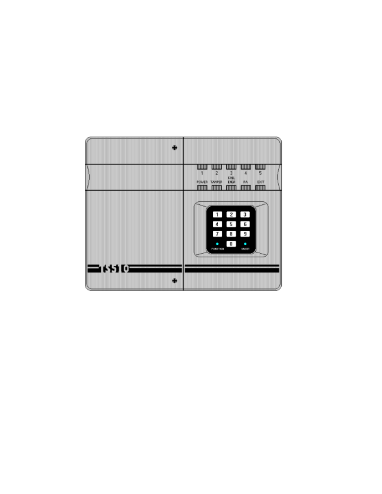
Figure 1 - TS510 ASSEMBLY LAYOUT
Page 4

Page 2 Issue 4: June 93
PRE-INSTALLA TION PA NEL TEST (OPTIONAL)
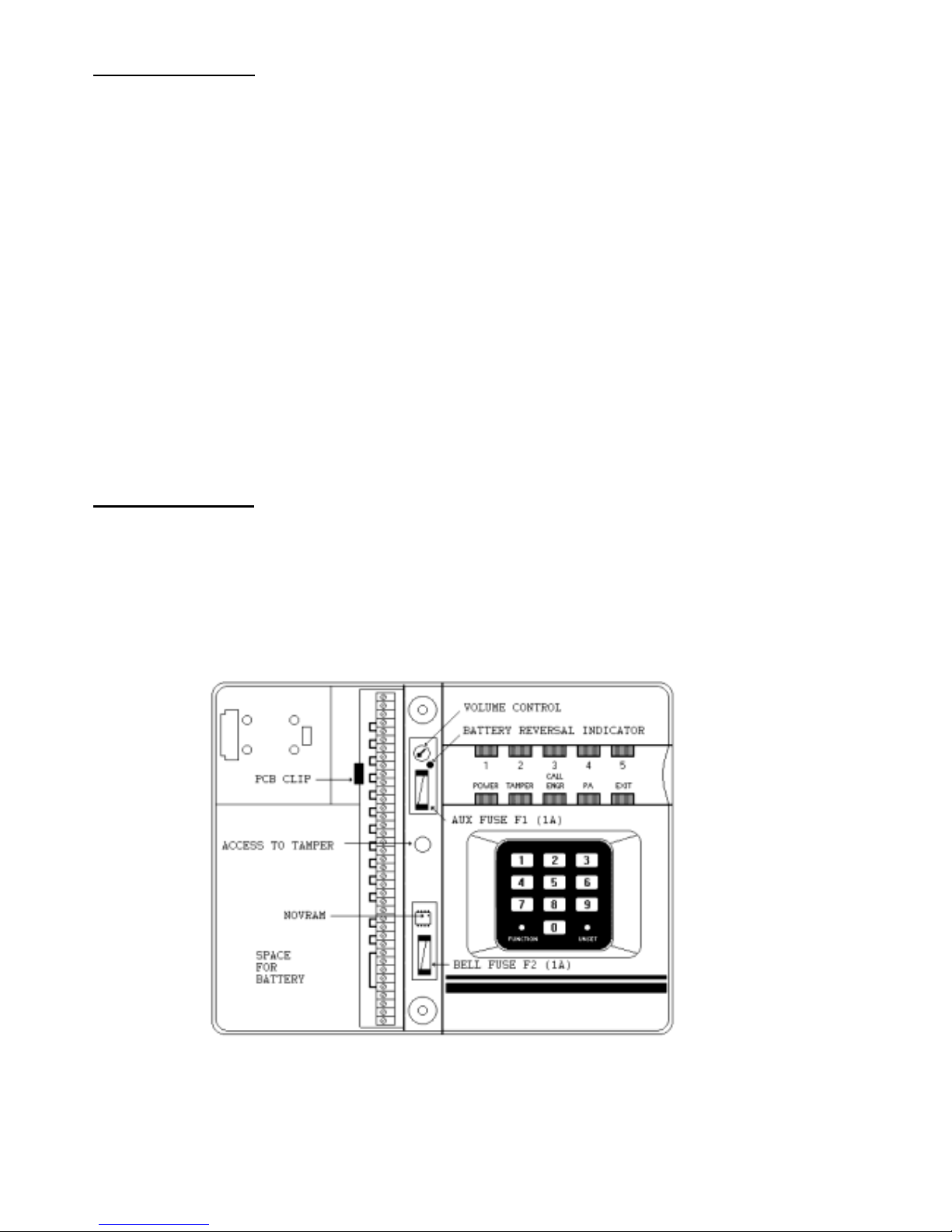
1 Unpack the TS510, remove the two screws from the front of the panel and lift away
the left hand cover. Disconnect the transformer leads, release the clip near the top of
the PCB and then carefully rem ove the complete right hand cover assembly.
CAUTION: Do not touch the surface of the PCB as this may cause static damage
to the product.
2 Connect the mains supply to the fused terminal block using a suitable cable, and then
replace the right hand cover assembly ensuring that it is securely c lipped in place and
the transformer leads are reconnected. Check that all the ZONE and TAMPER
terminal blocks are correctly linked out, then replace the left hand cover. (The battery
is not necessary at this stage)
3 Switch on the power and enter the default user code, [5678]. The [UNSET] LED will
flash and, after 5 seconds, the setting sequence will begin. Wait until the exit tone
ceases and a two tone confirmation signal is heard. The panel is now SET and the
[UNSET] LED is out.
4 With the panel still in the SET condition, remove the left hand cover thereby releasing
the tamper switch. Ensure that the sounder operates at full volume.
5 With the left hand cover still removed, enter [5678] to unset the panel ([UNSET] LED
on), and check that the [T AMPER] LED flashes.
Successful completion of this procedure indicates that the panel is working correctly and is
ready to install. If unsuccessful, switch off and re-apply the mains (ensuring that the Exit
Terminator is linked out to reset the system to factory defaults. Repeat the procedure and if
still unsuccessf ul c ontact your supplier.
INSTALLING THE PANEL
NOTE. THE PANEL MUST ONLY BE CONNECTED TO THE MAINS
VIA AN UNSWITCHED FUSED SPUR.
Remove the two screws from the front of the panel and carefully lift away the left hand cover.
Disconnect the transformer leads, release the clip near the top of the PCB and then remove
the complete right hand cover assembly. CAUTION: Do not touch the surface of the PCB
as this may cause static damage to the product.
Place the base on the wall where it is required and mark the screw positions. Remove the
base, then drill and plug the wall. Fix the base to the wall.
Connect the mains to the fused (160mA) terminal block in the panel, then replace the right
hand cover assem bly reme mbering to reconnect the transformer leads. The panel is now
ready to wire and progr amme.
NOTE: When connecting the battery, if the red LED near to the
AUX fuse is illuminated, then the battery has been incorrectly
connected or the battery volta ge is below 8 Volts. Disconnect the
battery and reconnect correctly, on reconnecting the battery the
LED will switch off.
Page 5
Issue 4: June 93 Page 3
SYSTEM WIRING
All ZONE and TAMPER inputs are linked out prior to despatch from the factory. Remove
these links from those zones which are to be used, but leave the links in unused zones. The
EXIT TERMINATOR link MUST BE REMOVED even if this facility is not used, otherwise all
programmed information will be lost on total power loss (mains and battery).
WHEN PLANNING AND INSTALLING THE WIRING:1 Ensure that the mains cable, circuit cables and telecom cables are kept separate, and
that mains cable enter s the housi ng as near to the fused terminal block as possible.
2 Ensure that the circuit, tamper and remote keypad cables are not routed adjacent to
AC or RF c abling and are not run in m ul ti c ore c abl es with bells or sounders.
3 Insulation testing should only be carried out when the cable under test is disconnected
from electronic circuitry at both ends.
Figure 2 - SAMPLE Wiring Diagram (showing Double Pole and End Of Line Resistor wiring)
Page 6

Page 4 Issue 4: June 93
AC IN: These are connected to the mains transformer via the two AC leads, (their
polarity is not critical).
AUX +/-: These provide auxiliary power for PIRs and other devices within the protected
area. T he system current consumption can be determined by measuring the
voltage across the two test pads located between the terminal blocks for circ uit
1 and circuit 2. Multiply the reading by 10 (eg. 30mV 300mA, 75mV
750mA) to give the current reading. The output is protected by a 1A fuse [FS1],
located near the terminal blocks (see Fig 1). Failure of [FS1] is indicated as a
tamper.
NOTE: THE TOTAL POWER CONSUMPTION MUST NOT EXCEED 750mA.
CIRCUITS 1-5: The zones can be wired using any combination of two different zone wiring
methods, called DOUBLE POLE (4 wire) or END OF LINE RESISTOR (2 wire).
- DOUBLE POLE: This is the conventional wiring method using
two wires for the alarm loop (wired across the [ZONE] terminal
blocks) and two for the tamper loop (wired across the [TAMP]
terminal blocks) (see Fig 2).
- END OF LINE RESISTORS: This method uses resistors on the
detection circuit, one (4K7) fitted across
each
alarm contact and
the other (2K2) in series with the loop at the furthest point (End
of Line). The 2 wires are connected between the outer terminal
blocks of the [ZONE] & [TAMP] connections, (see Fig 2 ).
The maximum number of detection devices connected to any zone is ten.
EXIT
TERM: This feature is required in some Police force areas and consists of a normally
open" push button positioned outside the last exit, used to finalise the setting
procedure. The Exit Terminator may be used with Timed Exit (when the
system will set within 5 seconds of pressing the button) or Last Exit setting
procedures (the button must be pressed after the Final Exit has been
operated), and can be programmed to Chime thereby acting as a door bell
when the system is unset. (See PROGRAMMING).
If shorted on power up, the panel will "factory reset", i.e. the factory default
settings will be loaded and any p reviously pro grammed data will be lost. The
Exit Terminator uses a single conventional wiring loop (i.e. no resistors) and
tamper prote ction is provided by the Aux Tamper loop, (see Fig 2).
KEY SW/F.EXIT This input can have one of two functions depending on how the system is
programmed:
KEYSWITCH - A "normally open" keyswitch can be connected to the control panel for
setting, part setting and unsetting the system. When the system is unset,
operating the switch will initiate the setting sequence and, when Set, the same
action unsets the system. Any c omb ination of keyswitch or keypad can be used
in the setting/unsetting sequence; for example the system could be set using
the keyswitch and then unset via the keypad or visa versa. To determine the
operation of the keyswitch ,see PROGRAMMING.
The keyswitch may be of either the spring ret urn momentary act ion type, or a
standard keyswitch with the key captive in the closed position.
Page 7

Issue 4: June 93 Page 5
SYSTEM WIRING (Cont.)
FINAL EXIT - The KEY SW/F.EXIT input can be alternatively used as a Final Exit zone, if so
programmed, thus providing a sixth zone.
The KEY SW/F.EXIT input uses a single conventional wiring loop, and the
tamper protection is provided by the Aux Tamper loop, (see Fig 2).
P./A. When activated, the PA (Personal Attack) zone causes a full alarm from the
panel and may a lso cause the external sounders to be activated. The PA zone
uses a single conventional wiring loop (i.e. no resistors) and tamper pro t e c t ion
is provided by the Aux Tamper loop, (see Fig 2)
AUX TAMPER These provide tamper protection for the P.A. and any other devices
connected to the control panel, (see Fig 2).
If 2 or more tamper circuits are to
be connected to
[AUX TAMP],
they must be wired in series.
NOTE: IF THE MAINS IS OFF AND THE BATTERY VOLTAGE
DROPS BELOW 10.5V, A TAMPER CONDITION WILL BE
GENERATED.
BELL TR- This provides the bell tamper return signal for the external sounder (bell or
siren) via a -ve return sig nal .
O/P 1 & O/P 2 These are programmable outputs which are +ve applied and can be selected
as any one of the following .
SW12V: Activates when the system sets, and de-activates on entry or on
alarm to activate latch indicators on movement detectors.
DETECTOR RESET: Normally acti ve, and de-activates when a passcode is
entered whilst the system is unset to reset latched detectors.
WALK TEST
(Output 1)
: Activates whilst the system is in walk test mode to
enable the walk test LED on movement detectors.
ALARM
(Output 1)
: Activates when a full alarm condition is detected.
P.A.
(Output 2)
: Activates when a P.A. alarm condition i s detected.
FAULT
(Output 2)
: Activates when a circuit is active duri ng the exit per i od.
+VE H/O This is used to provide the +ve hold off to external sounders, strobes etc. It is
protected by a 1A fuse [FS2], (see Fig 1). To gain access to FS2, remove the
left hand cover and the fuse will be seen below the NOVRAM.
NOTE: T HE TOTAL POWER CONSUMPTION OF THE SYSTEM
MUST NOT EXCEED 750mA.
H/O- This connection is used to provide -ve hold off to external sounders etc.
STB- This is a -ve applied output that can draw up to 250mA to drive strobes etc. It
switches on with the bell, and off when the panel is reset. Additionally, the
strobe will operate if the system fails to set during exit.
TRG- This is a -ve applied output which can draw up to 500mA to drive external
sounders. It switches on when the bell delay time expires, and off when the bell
duration time expi res , or when a passcode is enter ed.
L/S+ This output will drive a 16 (minimum) loudspeaker connected across L/S+ and
-VE H/O. The volume control is located above FS1 and allows adjustment of
the Entry /Exit and Chime tones (see Fig 1).
Page 8

Page 6 Issue 4: June 93
REMOTE KEYPAD
The option of up to 4 remote keypads (order code: TS510.REM) are supplied with an
interface which plugs onto the main panel PCB. The connections from the panel to the
Remote Keypad require a five core cable ( max length 50m).
Assuming that the control panel covers have been removed, the cable is in place and
that the mains supply and backup batte ry have been disconnected, installation is as
follows:
Connect the cable to the interface connections A, B, C etc. and then carefully loca te
the interface in the slot at the bottom of the panel PCB (see Fig 3). Replace the right
hand cover assembly.
Separate the remote keypad cover a ssembly f ro m the base by releasing the clips on
the top and bottom of the housing. Place the base on the wall where it is required and
mark the screw positions. Remove the base then drill and plug the wall. Fix the base
to the wall.
Taking care not to damage the PCB assembly, connect the terminal blocks on the
remote keypad to the cable, ensuring that the connections through to the control panel
interface card are A to A, B to B etc.
Carefully re-attach the front cover assembly to the base ensuring that the cable is
clear of the spring on the tamper switch, and the cover is se curely clipped to the base.
Finally re-connect the mains supply and test the operation of the remote keypad.
If more than 1 remote keypads are to be used, connections may be in a star or daisy
chain configuration.
DIGITAL COMMUNICATOR
The DC3 is an 8 channel plu g-on digital communicator specifically designed to operate with
Menvier control panels, and is supplied with a lead for connection directly onto the main
panel PCB. The unit has its own installation and programming instructions which must be
referred to before proceeding with installation. The digital communicator is mounted behind
the right hand lid assembly as appropriate.
CAUTION: The mains supply and backup battery mu st be disconnected before connecting
the DC3 to the main PCB.
Other communication devices such as the DC28 Digicom, RedCARE STU, Paknet Interface
Card etc. may be connected to the TS510 by usin g an optional interface card (TS510.IF).
This is also supplied with its own installation instructions which should be referred to before
proceeding with installation. Fig. 4 shows the TS510.IF connections when plugged onto the
TS510 PCB.
Page 9

Issue 4: June 93 Page 7
Fit the DC3 connector to the TS510 plug as shown.
Fig 3 - DC3 and TS510.REM Connections
Fit the TS510.IF to the panel plug taking care to ensure that
correct alignment is made and that no pins are visible.
Fig 4 - TS510.IF and TS510.REM Connection
Page 10

Page 8 Issue 4: June 93
QUICK REFERENCE GUIDE
FS1 (AUX 12V) FUSE = 1A
FS2 (BELL 12V) FUSE = 1A
MAINS FUSE = 160mA
OPTIONS 1
61 Bell duration
(20 mins)
62 Bell delay time
(0 mins)
63 Signalling options
ZONE LED 1 2 3 4 5
On for:
Bell= SAB No Abort Audible PA
PA audible on L.F.
Not used
Off for: Bell= SCB Abort Silent PA
PA silent on L.F.
OFF
64 Signalling of fire
On for: Unset Partset A Partset B
Full Set
Not used
65 Output 1
On for:
Walk test
SW12V Dtr reset Alarm Not used
66 Output 2
On for: Fault
SW12V
Dtr reset PA Not used
67 Keyswitch operati on
On for:
Full set
Part set A Part set B Final Exit Not used
68 Event log; Press 1 for newest event, 2 for oldest etc. Press 0 to exit
69 Setting options
On for:
Set allowed
with mains
failure
Rising Entry
and Exit
tones
Set allowed
with line fault
Not used Not used
Off for:
Set
disallowed
with mains
failure
Continuous
Entry and
Exit tones
Set
disallowed
with line
fault
Not used Not used
9 Options 2
On for: ET/FE Silent F.Exit set E.T. enabled Engr reset
3 rearms
Off for:
ET/FE
Chimes
Timed set E.T. disabled User reset
0 rearms
Page 11

Issue 4: June 93 Page 9
PROGRAMMING
The TS510 is very easy to program, using a combination of simple keystrokes, lights and
sounds. Additionally, there are two ways to speed up the process even further; 1) fill in the
programming record before you start, and 2) use the Default Settings where they c oincide
with your own requirements. These are factory programmed and appear when the mains
supply is first connected to the panel.
In order to save your programmed information the
Exit Terminator link MUST be removed as otherwise any subsequent interruption to
the mains supply will reset the panel to the Default Settings.
After each programming step has been successfully com pl et ed a two tone confirmation tone
will sound indicating that the panel has accepted the current information and is ready to
accept the next instruction. For some functions the tone is automatic (eg. setting t ime rs) but
for other functions it is given after pressing [0 ]. To assist programming, a [FUNCTION] LED
is provided which indicates the next keypress is to be a number (off) or a function (on).
The programming instructions should be left with the TS510 for future reference. They
assume that you have entered the Engineer Code (default setting = 1234) and the
[CALL ENGR] LED is lit indicating that the system is in the Engineer's Menu. The key
functions now change to those shown on the Quick Reference Guide. If any other LED is also
lit this shows which circuit created the last full alarm condition, (i.e. it acts as an automatic 1
event memory log). If the [CALL ENGR] LED is flashing at this stage, the last alarm
activation occurred whilst a line fault was present.
It is not necessary to programme the options in numerical order.
DEFAULTS
ENGINEER CODE = 1234 OPTIONS 1:
MASTER USER CODE = 5678 Bell output is SAB
LAST EXIT ZONE = ZONE 1 Alarm cleared on reset
ACCESS ZONE = ZONE 2 Audible P.A.
EXIT TIME = 30 SEC P.A. audible in line fault
ENTRY TIME = 30 SEC Fire output signals during Full Set
only
BELL DURATION = 20 MIN Output 1 is WALK TEST
BELL DELAY = 0 MIN Output 2 is SW12V
REMOTE RESET REF = 004 KEY SW/F.EXIT input is full set keyswitch
Set inhibited on mains fail
OPTIONS 2:
Exit Terminator chimes
Exit terminator disabled
Timed exit set
Auto rearm
User reset
NOTE:
IF THE EXIT TERMINATOR IS CLOSED AT POWER-UP,
ALL INFORMATION WILL BE RESET TO
THE DEFAULTS.
Page 12

TS510
PROGRAMMING GUIDE AND SYSTEM RECORDS
COMPLETE FORM USING BOXES PROVIDED AND LEAVE
WITH THE CONTROL PANEL FOR FUTURE REFERENCE
ENTER ENGINEER CODE AND THE
[CALL ENGR]
LED W ILL ILLUMINATE TOGETHER WITH
THAT OF THE ZONE W HICH CREATED THE LAST ALARM. IF THE
[CALL ENGR]
LED
FLASHES, THE LAST ALARM OCCURRED WITH A LINE FAULT PRESENT. OPTION
DEFAULTS ARE SHOWN IN
BOLD
.
To programme any of the zones (1 to 5) as standard
NIGHT
circuits, simply ensure that they are
not programmed as Last Exit, Access or Fire.
To program any of the zones (1 to 5) as
LAST EXIT
circuits, press
[1]
.
If any of the Zone LEDs
are ON, then these are already programmed with this option
. To change zones simply enter the
zone number, which will toggle the zone LED on/off. Once the setting is correct press
[0]
(END) and
listen for the confirmation tone.
LED 1 2 3 4 5
LAST EXIT
ON
/ OFF
ON / OFF ON / OFF ON / OFF ON / OFF
DEFAULT = ZONE 1 ONLY
To program any of the zones (1 to 5) as
ACCESS
circuits, press
[2]
.
If any of the Zone LEDs are
ON, then these are already programmed with this option
. To change zones simply enter the zone
number, which will toggle the zone LED on/off. Once the setting is correct press
[0]
(END) and
listen for the confirmation tone.
LED 1 2 3 4 5
ACCESS ON / OFF
ON
/ OFF
ON / OFF ON / OFF ON / OFF
DEFAULT = ZONE 2 ONLY
To program any of the zones (1 to 5) as
FIRE
circuits, press
[3]
.
If any of the Zone LEDs are ON,
then these are already programmed with this option
. To change zones simply enter the zone
number, which will toggle the zone LED on/off. Once the setting is correct press
[0]
(END) and
listen for the confirmation tone.
LED 1 2 3 4 5
FIRE ON / OFF ON / OFF ON / OFF ON / OFF ON / OFF
NO DEFAULT ZONES
EXIT TIME
:
Press
[4]
and 3 zone LEDs will light, indicating that a 3 digi t ex it ti me (i n secs) is
required. Once complete the confirmation tone will be heard.
eg. for 30 secs, enter 030
EXIT TIME s
DEFAULT = 030 SECS
ENTRY TIME
:
Press
[5]
and 3 zone LEDs will light, indicating that a 3 digit entry time (in secs) is
required. Once complete the confirmation tone will be heard.
eg. for 30 secs, enter 030
ENTRY TIME s
DEFAULT = 030 SECS
Page 13

BELL DURATION:
Press
[6] [1]
and 3 zone LEDs will light, indicating that a 3 digit bell duration
time (in mins) is required. Once complete, the confirmation tone will be heard.
eg. for 20 mins,
enter 020
BELL DUR. m
DEFAULT = 020 MINS
BELL DELAY: Press
[6] [2]
and 3 zone LEDs will light, indicating that a 3 digit bell delay time (in
mins) is required. Once complete the confirmation tone will be heard.
eg. for 5 mins, enter 005
BELL DELAY m
DEFAULT = 000 MINS
SIGNALLING OPTIONS: Press
[6] [3]
and combination of zone LEDs will light, each
showing a different setup:
LED 1 2 3 4 5
ON
BELL IS SAB NO ALARM
ABORT
AUDIBLE PA PA AUDIBLE
ON L.F.
NOT USED
OFF
BELL IS SCB ALARM ABORT SILENT PA PA SILENT ON
L.F.
NOT USED
SIGNALLING OF FIRE: Press
[6] [4]
combination of zone LEDs will light, each showing a
different setup:
LED 1 2 3 4 5
ON = FIRE
SIGNALLED
IN:
UNSET PARTSET A PARTSET B
FULL SET
NOT USED
ON / OFF ON / OFF ON / OFF ON / OFF NOT USED
OUTPUT 1: Press
[6] [5]
and
one
of the following LEDs will light, showing which function is
indicated by Output 1:
LED 1 2 3 4 5
ON FOR:
WALK
TEST
SW12V DTR RESET ALARM NOT USED
ON / OFF ON / OFF ON / OFF ON / OFF NOT USED
OUTPUT 2: Press
[6] [6]
and
one
of the following LEDs will light, showing which function is
indicated by Output 2:
LED 1 2 3 4 5
ON FOR: FAULT
SW12V
DTR RESET PA NOT USED
ON / OFF ON / OFF ON / OFF ON / OFF NOT USED
Page 14

KEYSWITCH/FINAL EXIT:
Press
[6] [7]
and
one
of the following LEDs will light, showing
how the keyswitch input w ill operate.
LED 1 2 3 4 5
ON
FOR:
FULL SET
PARTSET A PARTSET B FINAL E XIT NOT USED
ON / OFF ON / OFF ON / OFF ON / OFF NOT USED
VIEW EVENT LOG:
Pressing
[6] [8]
will allow the event log to be viewed. Pressing
[8]
displays
the last event whilst pressing numbers other than
[9]
and
[0]
displays earlier events in order, with
[1]
being the oldest event. To exit the routine, press
[0]
.
SYSTEM SET WITH MAINS FAIL
: Press
[6] [9]
to select the system setti ng options.
LED 1 2 3 4 5
ON FOR: SET ALLOWED
WITH MAINS
FAILURE
RISING ENTRY
AND EXIT
TONES
SET ALLOWS
WITH LINE
FAULT
NOT USED NOT USED
OFF FOR:
SET
DISALLOWED
WITH MAINS
FAILURE
CONTINUOUS
ENTRY AND
EXIT TONES
SET
DISALLOWED
WITH LINE
FAULT
NOT USED NOT USED
ENGINEER CODE:
Press
[7]
and 4 zone LEDs will light indicating that a 4 digit engineer code
is required. Once ent ered, r e-enter the code for confirmation and listen for the confirmation tone.
ENGR CODE
DEFAULT = 1234
REMOTE RESET CODE:
Press
[8]
and 3 zone LEDs will light, indicating that a 3 digit code
must be entered. Enter your code and listen for the confirmation tone.
RESET NO.
DEFAULT = 004
OPTIONS:
Press
[9]
and a combination of zone LEDs will light, each showing a different setup.
To change any option, simply enter the number for the options required. Once the settings are
correct, press
[0]
and listen for the confirmation tone.
LED 1 2 3 4 5
ON FOR: ET/F EXIT
SILENT
FINAL EXIT
SET
E.T.
ENABLED
ENGINEER
RESET
3 REARMS
OFF FOR:
ET /F EXIT
CHIMES
TIMED EXIT E.T.
DISABLED
USER
RESET
0 REARMS
NOTE: Whilst in engineer mode, tampers are inhibited. To monitor tampers return the panel
to the UNSET condition.
 Loading...