

Page 1
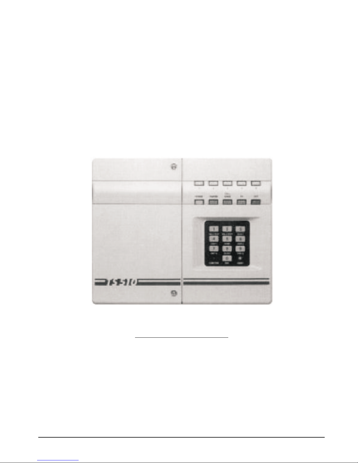
TS510 & TS500
Installation & User Guide
Compatible Equipment
TS510 REM - Remote Keypad
9040 - Loudspeaker
DC54/58 - Digital Communicator
SD1+ - Speech Dialler
496525 Issue A 1 of 10 TS510 and TS500
Page 2
Overview
Introduction
This installation manual is intended to help you install
the TS510 as quickly and easily as possible. It is
therefore very important to read the manual
thoroughly before starting any work. This is particularly
significant if it is your first TS510 installation.
The TS500 was the predecessor to the TS510. The
differences between the two panels are noted
throughout this guide.
Specification
5 Programmable Zones with individual Tamper circuits,
plus fixed PA and Exit Terminator Outputs for Bell,
Strobe and 16 Ohm Loudspeaker
Optional Remote Keypad (1 only) and Keyswitch
Plug-on digicom DC3 or plug-on interface
(TS500/510.IF) for connection to digicoms DC3,
Redcare STU, Paknet etc.
Conforms to BS4737: Part 1: 1986
Input Voltage: 240V +
10% 50Hz
Panel DC Current: 30mA, 100mA in alarm
REM DC Current: 10mA
Current Available: 750mA MAX (AUX + Bell
Current)
Battery Capacity: 12V, 2.6/3.2Ahr (batteries not
supplied)
Dimensions: W x H x D 260 x 213 x 85mm
Weight Panel 1.5Kg
Remote Keypad 125 x 127 x 32mm
Weight Keypad 200g
Environment: 0° - 55° C (INDOORS)
TS510 & TS500 2 of 10 496525 Issue A
TS510 & TS500
123
456
789
0
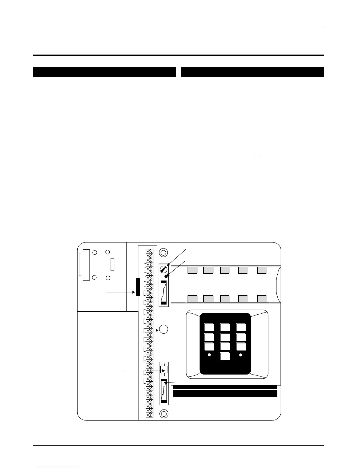
PCB CLIP
ACCESS TO TAMPER
SPACE
FOR
BATTERY
NOVRAM
BELL FUSE F2 (1A)
AUX FUSE B1 (1A)
BATTERY REVERSAL INDICAT O R
VOLUME CONTROL
12
34
5
POWER TAMPER
CALL
ENGR
PA
EXIT
UNSET
FUNCTION
Figure 1 - TS510 Assembly Layout
Page 3
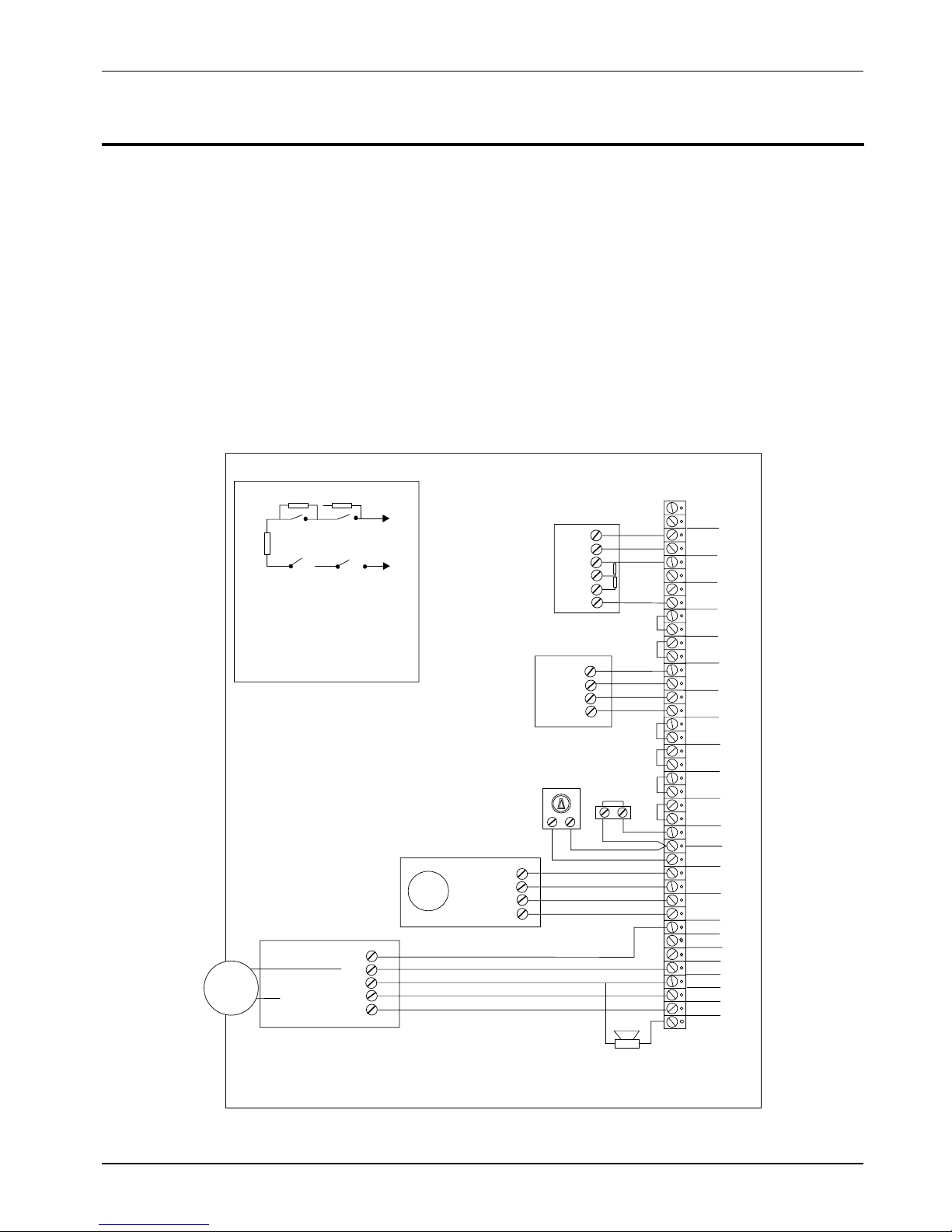
System Wiring
All ZONE and TAMPER inputs are linked out prior to
despatch from the factory. Remove these links from
those zones which are tobe used, but leave the links in
unused zones. The EXIT TERMINATOR link MUST BE
REMOVED even if this facility is not used, otherwise all
programmedinformationwillbe lost ontotalpowerloss
(mains and battery).
PLANNING AND INSTALLING THE WIRING:-
1. Ensure that the mains cable, circuit cables and
telecom cables are kept separate, and that mains
cable enters the housing as near to the fused
terminal block as possible.
2. Ensure that the circuit, tamper and remote keypad
cables are not routed adjacent to AC or RF cabling
and are not run in multicore cables with bells or
sounders.
3. Insulation testing should only be carried out when
the cable under test is disconnected from
electronic circuitry at both ends.
NOTE: TS500 Aux TMP = Main & Bell TMP
OP1 = WLK TST
OP2 = SW 12V
496525 Issue A
3 of 10 TS510 & TS500
TS510 & TS500
ALARM
TAMPER
Normally
Closed
P. A . B ut t o n
Normally
Open
Keyswitch
Normally
Open
Pushbutton
Alarm
Tamper
ALARM
TAMPER
0V
+12V
MOVEMENT DETECTOR
WIRED END OFLINE
MAGNETIC
CONTACT
WIRED
DOUBLE POLE
- VE STROBE TRIGGER
-VE BELL TRIGGER
STROBE
-
+
-VE TAMPER RETURN
S.A.B/SIREN
16 0HM
LOUDSPEAKER
STB -
H/O
O/P1
BELL TR-
AC
IN
AUX 12V
ZONE 1
ZONE 2
TAMP 1
TAMP
TAMP
ALM
ALM
2K24K7
2K2
TO
ZONE
2K2 (2200) OHMS
RED RED RED
END OF LINERESISTOR
4K7 (4700) OHMS
YELLOW VIOLET RED
SHUNT RESISTOR
TAMP2
ZONE3
ZONE 4
TAMP 3
ZONE 5
EXIT TERM
TAMP 5
KEYSW/
F. E XI T
AUX TMP
P. A .
TAMP 4
O/P2
+
-
L/S+
TRG -
+12 V
0V
4K7
2K2
+
-
Fig 2 SAMPLE Wiring Diagram (showing Double Pole and End of Line Resistor wiring)
Page 4

TS510 & TS500
Remote Keypad
Up to 4 remote keypads (order code: TS510 REM), can
be fitted, these are supplied with an interface which
plugs onto the main panel PCB. The connections from
the panel to the Remote Keypad require a five core
cable (max length 50m).
Assuming that the control panel covers have been
removed, the cable is in place and that the mains
supply and backup battery have been disconnected,
installation is as follows:
1. Connect the cable to the interface connections A,
B, C etc, and then carefully locate the interface in
theslotat the bottomofthepanel PCB. Replacethe
right hand cover assembly.
2. Separate the remote keypad cover assembly from
the base by releasing the clips on the top and
bottom of the housing. Place the base on the wall
where it is required and mark the screw positions.
Removethebasethendrill and plug thewall. Fixthe
base to the wall.
3. Taking care not to damage the PCB assembly,
connect the terminal blocks on the remote keypad
to the cable, ensuring that the connections through
to the control panel interface card are A to A, B to B
etc.
4. Carefully re-attach the front cover assembly to the
baseensuringthatthecableisclear of the spring on
thetamperswitch,and the coverissecurelyclipped
to the base. Finally re-connect the mains supply
and test the operation of the remote keypad.
5. If more than 1 remote keypad is to be used,
connections may be in a star or daisy chain
configuration.
NOTE: TS500 only compatible with TS500 REM.
NOTE: TS500 only, link (LKI). If open the remote
keypad will have full functions if closed you
can only use remote keypad to set, part set
and unset.
NOTE: TS500 Only one remote keypad can be fitted
Digital Communicator
The DC3 is an 8 channel plug-on digital communicator
specifically designed to operate with Menvier Security
control panels, and is supplied with a lead for
connection directly onto the main panel PCB. The unit
has its own installation and programming instructions
which must be referred to before proceeding with
installation. The digital communicator is mounted
behind the right hand lid assembly as appropriate.
CAUTION: The mains supply and backup battery must
be disconnected before connecting the DC3 to the
main PCB.
Other communication devices such as the DC28
Digicom,RedCARESTU,Pakent InterfaceCardetc. may
be connected to the TS510 by using an optional
interfacecard(TS510.IF). Thisisalsosuppliedwith its own
installation instructions which should be referred to
before proceeding with installation. Fig. 4 shows the
TS510.IF connections when plugged onto the TS510
PCB. (See page 5)
TS510 & TS500 4 of 10 496525 Issue A
Page 5

TS510 & TS500
TS510 Digital Communicator Wiring
Fit the DC3 connector to the TS510 plug as shown.
Fit the TS510.IF to the panel plug taking care to ensure
that correct alignment is made and that no pins are
visible.
TS500 Digital Communicator Wiring
Fit the DC3 connector to the TS500 plug after
removing the polarity pin from socket 4. Ensure that
the connector is fitted with the wings pointing away
from the TS500 PCB, and the shorting link (or 2 spare
pins) are above the connector.
Remove the shorting link (if fitted) from the top 2 pins
of the DIGI INTERFACE connector. Fit the TS500/510.IF
to the panel plug taking care to ensure that correct
alignment is made and that no pins are visible.
496525 Issue A
5 of 10 TS510 & TS500
TO REMOTE
KEYPAD
TO DC 3.
DC 3 CHANNELS
1=FIRE
2=PA
3=ALARM
4
=SET/UNSET
5
=ENGINEER-ON-SITE
DIGI
INTERF ACE
REMOTE INTERFACE
SPARE,PINS OR
SHORTING LINK
Fig 5 DC3 and TS500.REM Connections
TO REMOTE
KEYPAD
REMOTEINTERFACE
DIGI
INTERFACE
T
ERMINAL BLOCKS(top to bottom)
LINE F AULT (+veapplied during linefault)
0V
12V
8=SOUNDERON
7=BELLON
6=PARTSET
5 =ENGINEER - ON - SITE
4=SET/UNSET
3=ALARM
2=PA
1 =FIRE
LF
0V
12V
8
7
6
5
4
3
2
1
Fig 6 TS500/510.IF and TS500.REM Connections
TO REMOTE
KEYPAD
REMOTEINTERFACE
DIGI
INTERFACE
T
ERMINAL BLOCKS(top to bottom)
LINE F AULT (+veApplied in Line Fault)
0V
12V
8=FAULT
7 =DET RESET
6 =SW 12V
5 =ENGINEER -ON - SITE
4=SET/UNSET
3=ALARM
2=PA
1 =FIRE
LF
0V
12V
8
7
6
5
4
3
2
1
Fig4 TS510.IF and TS510.REM Connection
TO REMOTE
KEYPAD
TO DC 3.
DC 3 CHANNELS
1=FIRE
2=PA
3 = ALARM
4
= SET/UNSET
5
= ENGINEER-ON-SITE
DIGI
INTERFACE
REMOTEINTERFACE
Fig 3 DC3 and TS510.REM Connections
Page 6

Defaults
Key Functions
TS510 & TS500
TS510 & TS500 6 of 10 496525 Issue A
ENGINEER CODE = 1234 OPTIONS 1: (NOT APPLICABLE TO TS500)
MASTER USER CODE = 5678 Bell output is SAB
LAST EXIT ZONE = ZONE 1 Alarm cleared on reset
ACCESS ZONE = ZONE 2 Audible P.A.
EXIT TIME = 30 secs. P.A. audible in line fault
ENTRY TIME = 30 secs. Fire output signals during Full Set only
BELL DURATION = 20 min. Output 1 is WALK TEST
BELL DELAY = 0 min. Output 2 is SW12V
REMOTE RESET REF = 004 KEY SW/F.EXIT input is
full set keyswitch Set inhibited on mains fail
OPTIONS 2: (NOT APPLICABLE TO TS500)
Exit Terminator chimes
Exit Terminator disabled
Timed exit set
Auto rearm
User reset
Engineer’s Reset
1. Enter Engineer code default 1234. The CALL ENGR
LEDwillilluminate. YouarenowinEngineermode.
2. Press 0 twice to return to unset.
Loading Defaults
1. Power down panel mains and battery.
2. Wire in a small piece of cable across two terminals
for exit terminator.
3. Power up battery and mains.
4. Enter 1234 and remove link.
5. The panel is now back to Factory Default
Programming.
Bell Test/Walk Test
Please refer to user function numbers 1 & 2
respectively.
Page 7

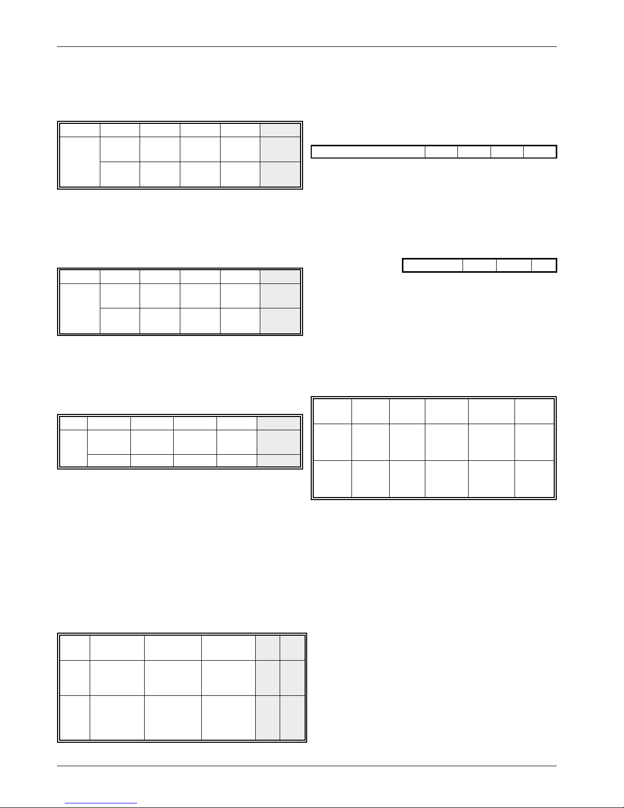
Engineers Programming
ENTER ENGINEER CODE AND THE [CALL ENGR] LED WILL
ILLUMINATE TOGETHER WITH THAT OF THE ZONE WHICH
CREATED THE LAST ALARM. IF THE [CALL ENGR] LED
FLASHES, THE LAST ALARM OCCURRED WITH A LINE FAULT
PRESENT. OPTION DEFAULTS ARE SHOWN IN BOLD.
To program any of the zones (1 to 5) as standard
NIGHT circuits, simply ensure that they are not
programmed as Last Exit, Access or Fire.
To program any of the zones (1 to 5) as LAST EXIT
circuits, press [1]. If any of the Zone LED’s are ON, then
these are already programmed with this option. To
change zones simply enter the zone number, which
will toggle the zone LED on/off. Once the setting is
correct press [0] (END) and listen for the confirmation
tone.
LED12345
LAST EXIT
ON/OFF ON/OFF ON/OFF ON/OFF ON/OFF
DEFAULT = ZONE 1 ONLY
To program any of the zones (1 to 5) as ACCESS
circuits, press [2] , If any of the Zone LED’s are ON, then
these are already programmed with this option. To
change zones simply enter the zone number, which
will toggle the zone LED on/off. Once the setting is
correct press [0] (END) and listen for the confirmation
tone.
LED12345
ACCESS: ON/OFF ON/OFF ON/OFF ON/OFF ON/OFF
DEFAULT = ZONE 2 ONLY
To program any of the zones (1 to 5) as FIRE circuits,
press [3]. If any of the Zone LED’s are ON, then these
are already programmed with this option. To change
zones simply enter the zone number, which will toggle
the zone LED on/off. Once the setting is correct press
[O] (END) and listen for the confirmation tone
LED12345
ON FOR: ON/OFF ON/OFF ON/OFF ON/OFF ON/OFF
NO DEFAULT ZONES
EXIT TIME: Press [4] and 3 zone LED’s will light, indicating
that a 3 digit exit time (in secs) is required, Once
complete the confirmation tone will be heard. e.g. for
30 secs. enter 030
EXIT TIME S
DEFAULT = 030 SECS
ENTRY TIME: Press [5] and 3 zone LED’s will light,
indicating that a 3 digit entry time (in secs) is required,
Once complete the confirmation tone will be heard
e.g. for 30 secs. enter 030
ENTRY TIME S
DEFAULT = 030 SECS
BELL DURATION:
Press [6] [1] and 3 zone LED’s will light,
indicating that a 3 digit bell duration time (in
mins) is required. Once complete, the
confirmation tone will be heard. e.g. for 20
mins, enter 020.
BELL DUR. m
DEFAULT = 020 MINS
BELL DELAY:
Press [6] [2] and 3 zone LED’s will light,
indicating that a 3 digit bell delay time (in
mins) is required. Once complete the
confirmation tone will be heard. e.g. for 5
mins, enter 005
BELL DELAY m
DEFAULT = 000 MINS
OPTIONS: 63 - 69 Not applicable to TS500
SIGNALLING OPTIONS:
Press [6] [3] and combination of zone LED’s will
light, each showing a different setup:
LED12345
ON
OFF
BELL IS
SABNOALARM
ABORT
AUDIBLEPAPA
AUDIBLE
ON L.F
NOT
USED
BELL IS
SCB
ALARM
ABORT
SILENT
PA
PA
SILENT
ON LF
NOT
USED
SIGNALLING OF FIRE:
Press [6] [4] and combination of zone LEDs will
light, each showing a setup:
LED 12345
ON = FIRE
SIGNALLED
IN:
UNSET PARTSETAPARTSETBFULL SET NOT
USED
ON/OFF ON/OFF ON/OFF ON/OFF NOT
USED
496525 Issue A 7 of 10 TS510 & TS500
TS510 & TS500
Page 8
TS510 & TS500
OUTPUT 1:
Press [6] [5] and one of the following
LEDs will light, showing which function
is indicated by Output 1:
LED12345
ON
FOR:
WALK
TEST
SW12V DTR
RESET
ALARM NOT
USED
ON/OFF ON/OFF ON/OFF ON/OFF NOT
USED
OUTPUT 2:
Press [6] [6] and one of the following
LEDs will light, showing which function
is indicated by Output 2:
LED12345
ON
FOR:
FAULT SW 12V
DTR
RESET
PA NOT
USED
ON/OFF ON/OFF ON/OFF ON/OFF NOT
USED
KEYSWITCH FINAL EXIT:
Press [6] [7] and one of the following LEDS
will light, showing how the keyswitch input will
operate.
LED 1 2 3 4 5
ON
FOR:
FULL SET
PART SET
A
PART SETBFINAL
EXIT
NOT USED
ON/OFF ON/OFF ON/OFF ON/OFF NOT USED
VIEW EVENT LOG:
Pressing [6] [8] will allow the event log to be
viewed. Pressing [8] displays the last event
whilst pressing numbers other than [9] and
[0] displays earlier events in order, with [1]
being the oldest event. To exit the routine,
press [0].
SYSTEM SETTING OPTIONS:
Press (6) [9] to select the system setting
options.
LED 1 2 3 4 5
ON
FOR:
SET ALLOWED
WITH MAINS
FAILURE
RISING ENTRY
AND EXIT
TONES
SET ALLOWS
WITH LINE
FAULT
NOT
USED
NOT
USED
OFF
FOR:
SET
DISALLOWED
WITH MAINS
FAILURE
CONTINUOUS
ENTRY AND
EXIT TONES
SET
DISALLOWED
WITH LINE
FAULT
NOT
USED
NOT
USED
ENGINEER CODE:
Press [7] and 4 zone LEDs will light indicating
that a 4 digit engineer code is required.
Once entered, re-enter the code for
confirmation and listen for the confirmation
tone.
ENGR CODE
DEFAULT = 1234
REMOTE RESET CODE:
Press [8] and 3 zone LEDs will light, indicating
that a 3 digit code must be entered. Enter
your code and listen for the confirmation
tone.
RESET NO.
DEFAULT = 004
OPTIONS:
Press [9] and a combination of zone LEDs will
light, each showing a different setup. To
change any option, simply enter the number
for the options required. Once the settings
are correct, press [0] and listen for the
confirmation tone.
LED 1 2 3 4 5
ON
FOR:
ET/F EXIT
SILENT
FINAL
EXIT
SET
E.T.
ENABLED
ENGINEER
RESET3REARMS
OFF
FOR:
ET/F
EXIT
CHIMES
TIMED
EXIT
E.T.
DISABLED
USER
RESET0REARMS
NOTE: Whilst in engineer mode, tampers are
inhibited. To monitor tampers return the panel to the
UNSET condition.
NOTE: OPTIONS: No.5 on TS500 LED ON = AUTO
RE-ARM, LED OFF = MANUAL RE-ARM
TS510 & TS500 8 of 10 496525 Issue A
Page 9

User Functions
SETTING THE SYSTEM
1. Enter your passcode - the (UNSET) light will
flash.
2. Wait 5 secs until the (FUNCTION) light goes out
and the exit tone will start. Leave via the
designated exit route, closing the door.
3. The system is set when the exit tone stops and
the two tone confirmation tone is heard.
NOTES:
A) If the exit tone continues and (if fitted) the
strobe light on the bell box is flashing the
system has not set and you must re-enter the
premises, re-enter the passcode and start
again.
B) If you change your mind whilst setting the
panel and wish to unset it again press (0) (END)
or wait until the (FUNCTION) light goes out and
re-enter your passcode.
PART SET THE SYSTEM
1. Enter your passcode - the (UNSET) light will flash
2. Press [7] (OMIT A) OR [9] (OMIT B) as appropriate
- the zones omitted will flash.
3. After a pause the exit tone will start.
4. The system is part set when the exit tone stops.
The following options may be accessed by entering
the USER 1 passcode IN REVERSE ORDER
(eg for
passcode 5678 - enter 8765) followed within 5
seconds by the function key you require. These
facilities are not available to User 2 who is restricted
to Set, Part-set and Unset activities.
NOTE: TS500 enter code in forwards and not in
reverse for following functions
Testing Sounders
1. Enter User 1 passcode IN REVERSE and the
tone will start - press [1] (BELL TEST) immediately.
2. All panel lights illuminate followed by 5 second
sequential activations of internal sounders,
external sounders and strobe (if fitted).
3. Panel returns to [UNSET] condition on
completion of testing.
Testing Detectors
1. Enter User 1 passcode IN REVERSE and the
tone will start - press [2] (WALK TEST)
immediately.
2. Activate selected detectors or door contacts
and smoke detectors if fitted.
3. Zone light illuminates and two tone sounder is
heard for each device activated.
4. Press [0] (END) to complete test - [UNSET] will
illuminate.
Change User 1 Passcode
1. Enter User 1 passcode IN REVERSE and the
tone will start - press [4] (USER 1) immediately
2. Four zone lights illuminate and 15 seconds is
allowed to commence entry of the new code.
3. Enter new passcode extinguishing the four
zone lights.
4. Four zone lights illuminate again.
5. Repeat new passcode (as confirmation).
6. Two tone confirmation sound heard - new
passcode accepted - [UNSET] will illuminate.
Change User 2 Passcode
1. Enter User 1 passcode IN REVERSE and the
tone will start - press [6] (USER 2) immediately.
2. Four zone lights illuminate and 15 seconds is
allowed to commence entry of the new code.
3. Enter new User 2 passcode extinguishing the
four zone lights.
4. Four zone lights illuminate again.
5. Repeat new User 2 passcode (as
confirmation).
6. Two tone confirmation sound heard - new User
passcode accepted - [UNSET] will illuminate.
Selecting Chime
With the system unset you may wish to be alerted
when door contacts or detectors are activated. You
can set nominated devices to “CHIME”:
1. Enter User 1 passcode IN REVERSE and the
tone will start - press [5] (CHIME) immediately.
2. Any zones set to chime will illuminate.
3. To add or delete chime zones press the
relevant zone number within 15 seconds.
4. Zone lights indicate status (LIT=CHIME,
UNLIT=NORMAL).
5. When satisfied press [0] (END).
6. Two tone confirmation sound heard - [UNSET]
will illuminate.
Change Part Set Areas
If you wish to re-arrange your part-set areas:
1. Enter User 1 passcode IN REVERSE and the
tone will start - press [7] (OMIT A) OR
[9] (OMIT B)
immediately as required.
2. Zone lights flashing indicate those zones
omitted
3. To add or delete omit zones press the relevant
zone number within 15 seconds.
4. Zone lights indicate status
496525 Issue A
9 of 10 TS510 & TS500
TS510 & TS500
Page 10

TS510 & TS500
(FLASHING=OMITTED, UNLIT=NORMAL)
5. When satisfied press [0] (END).
6. Two tone confirmation sound heard - [UNSET]
will illuminate.
Fault finding
[CALL ENGR] flashing
Indicates there is a telephone line problem if
you are connected to a monitoring station.
Check telephone and call engineer.
[CALL ENGR] illuminated
Try re-set procedures or call engineer.
[TAMPER] illuminated or flashing
The panel sounder will probably be bleeping
and a zone light: may be flashing.
1. Enter passcode to stop sounder
2. Check detection devices in zone indicated
3. If you can correct the fault do so and then
enter your passcode and press [0] (END).
System returns to UNSET
4. If fault cannot be remedied - call your
engineer.
(PA) illuminated
1. Manually reset Panic button with the key
provided
2. Enter your passcode - PA indicator on
3. Enter your passcode and press [0] (END).
[POWER] light out
This will occur if there is a mains failure or power cut
when the system will switch to reserve battery power
for about 8 hours. If the power cut persists the system
will go into alarm. If this happens enter your passcode
to unset the system and call your engineer.
TS510 & TS500 10 of 10 496525 Issue A
 Loading...