

Page 1

TS2500
Intruder Alarm Control Panel
Operators Manual
Page 2

CONTENTS
Overview ............................................................................................ 1
Glossary of Terms............................................................................................1
Introduction ....................................................................................................3
Circuits & Wards..............................................................................................4
Communication Devices ...............................................................................5
Remote Keypads............................................................................................6
Operation........................................................................................... 8
Introduction ....................................................................................................8
Using the Set/Unset Menu ...............................................................................9
Setting Your Ward(s) ......................................................................................10
Setting with Circuits in Fault ...........................................................................12
Unsetting Your Ward(s)...................................................................................13
Part Setting the System .................................................................................15
Part Unsetting the System..............................................................................16
Setting with Circuits Omitted ..........................................................................17
Viewing Error Circuits .....................................................................................18
Unsetting after an Alarm.....................................................................................19
Resetting after an Alarm.....................................................................................20
User Menu 1 ..................................................................................... 22
Introduction ..................................................................................................22
Testing Bells & Sounders.....................................................................................23
Walk Testing Circuits......................................................................................24
Use Remote Reset ........................................................................................25
Changing Your Passcode .............................................................................26
Selecting Chime...........................................................................................27
Omitting a 24hr Group .................................................................................28
Omitting Circuits ...........................................................................................29
Silent Set Wards.............................................................................................30
Set/Unset Menu.............................................................................................31
Selecting User Menu 2 ..................................................................................32
Fault Finding ..................................................................................... 33
Display Messages .........................................................................................33
Records ............................................................................................ 37
System Details...............................................................................................37
User Details ...................................................................................................38
Circuit Details................................................................................................40
Service Record .............................................................................................44
Installer Information ......................................................................................45
Page 3

1
Overview
Glossary of Terms
Alarm Receiving Centre
A permanently manned monitoring station used
to receive alarm signals from an alarm system.
Chime
A facility which allows selected detection circuits
to generate a two tone sound when triggered.
Detection Circuit
All detection devices, (e.g. magnetic contacts,
movement sensors) are connected to detection
circuits. Each circuit is allocated a number
which identifies the detection device. For
example, a room protected by a movement
sensor may be "Circuit 1001", while a door
protected by a magnetic Contact may be
"Circuit 1002".
Digital Communicator
A signalling device fitted to the system which will
transmit alarm information via the telephone
line to the alarm receiving centre.
Downloading
A process which allows the alarm system to be
remotely interrogated and programmed using a
computer and modem.
Duress
A means of entering a passcode which
generates a silent alarm via the signalling
device (if fitted) to a the alarm receiving centre.
Entry Time
A pre-set time delay to allow the user to enter
the protected area and access the remote
keypad without causing an alarm.
Event Log
A record of system activity which is stored in
memory (maximum of 4000 events).
Exit/Entry Route
The route which must be used when entering or
leaving the protected area when the alarm
system is being set.
Exit Terminator
An external push button switch used to
complete the setting of the alarm system.
Exit Time
A pre-set time delay to allow the user to leave
the protected area after initiating the setting
procedure.
Final Exit
The door or detector used when leaving and
entering the protected area.
Full Set
The state of the alarm system when it is
protecting all areas of the premises.
Page 4

2
Overview
Glossary of Terms
Master User
The user(s) who has the authority for assigning
new users to the alarm system.
Modem
A device for transmitting and receiving data to
and from a computer via the telephone line.
Omit
To intentionally exclude the monitoring of one or
more detection circuits when setting the alarm
system.
P.A(Panic Alarm)
An emergency push button switch used to
activate an alarm. The alarm signal will also be
transmitted to the alarm receiving centre if a
signalling device is fitted to the alarm system.
Part Set
The state of the alarm system when it is
protecting part of the premises.
Passcode
A unique number which must be entered
before the alarm system can be operated.
Remote Keypad
A device located away from the main control
panel that is used to operate the alarm system.
Reset
The action required to return the alarm system
to its normal state after an alarm condition.
Set
To arm one or more wards.
System Open
The status of the system when all wards are
unset.
Tamper Alarm
An alarm caused by the system being physically
interfered with.
24hr Circuit
A circuit that is monitored at all times.
Unset
To disarm one or more wards.
Users
Persons allocated a passcode which allows
them to operate the alarm system.
Wards
A group of detection circuits that can be set or
unset independently of each other.
Page 5

3
Overview
Introduction
The TS2500 is an advanced security alarm
control system using state of the art
electronics to provide comprehensive but
flexible protection for both large domestic
and commercial premises. The system
comprises of a number of components
linked to a central control unit which is
concealed from view but accessible for
maintenance.
This manual describes the basic operating
procedures for your alarm system. For
details of all operating procedures refer to
the "Managers Operating Manual".
To avoid unnecessary operating errors
please discuss the details of your alarm
system with your alarm company or
master user before attempting to use it.
Also ensure that alarm company
completes the system record sheets at
the back of this manual.
Page 6
4
Overview
Circuits & Wards
Detection Circuits
A maximum of 1040 detection circuits
can be monitored by the TS2500 alarm
system. Each circuit is allocated a unique
4 digit circuit number and a 16 character
text description which is used to identify
the particular circuit. Your alarm company
will have programmed each circuit to
respond in a certain way when the circuit
is activated during the set or unset state.
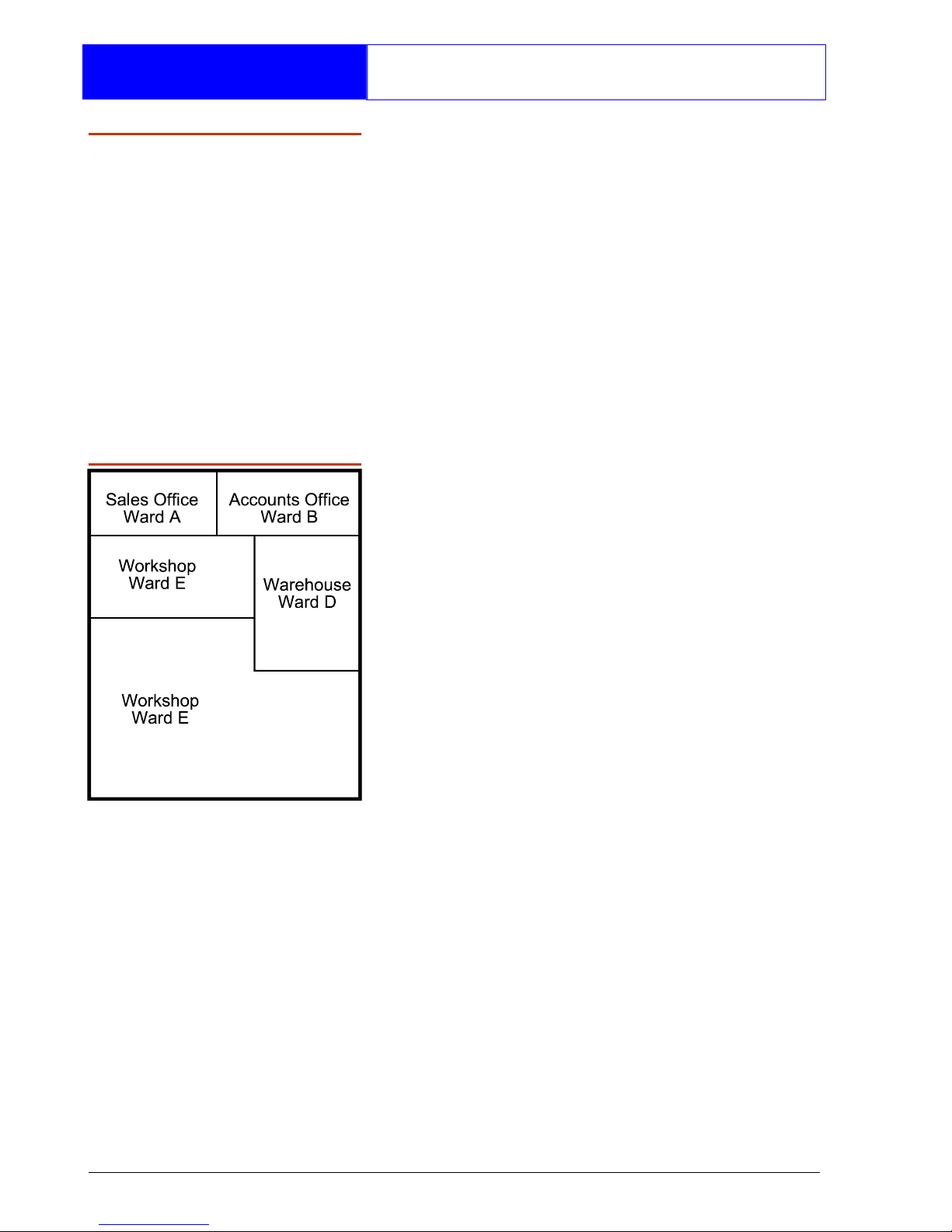
Wards allow the system to be broken
down into specific areas so that parts of
the system can be set and unset
independently, Users can be given
access to all wards or limited to specific
wards. If a user does not have access to
a particular ward they cannot set or unset
that ward.
Wards
The TS2500 can be broken down into 16
wards, each ward is identified using the
letters A - P. When the system is part set
the display will show which wards are
currently set.
Page 7
5
Overview
Communication Devices
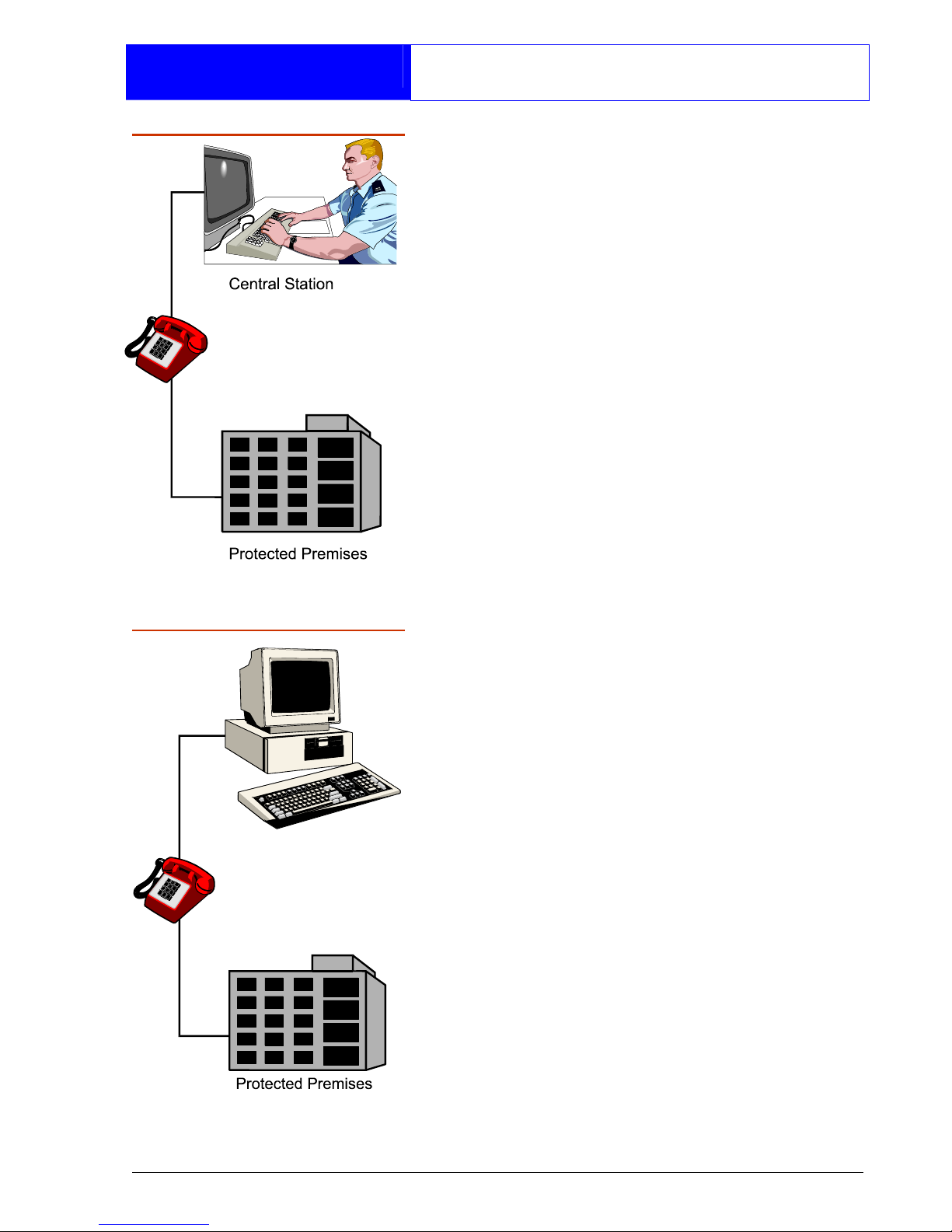
Your alarm system may be fitted with a
digital communicator or RedCARE unit.
The device is connected to your
telephone line and in the event of an
alarm activation, the device will signal the
alarm condition to the alarm receiving
centre. Where upon the necessary police
action can be taken.
If your system has been fitted with such a
device it is very important that you fully
understand how to operate your alarm
system. Operator misuse may result in
the police attending your premises
under false conditions.
Remote Signalling
Downloading
A personal computer (PC) can be linked
into your alarm system via the telephone
line to allow remote programming and
testing of the alarm system. This feature is
known as "Downloading" and is normally
performed by your alarm company or
alarm receiving centre with your
authorisation. An example of this feature
would be for your alarm company to dial
into your alarm system and adjust your
entry time.
Page 8
6
Overview
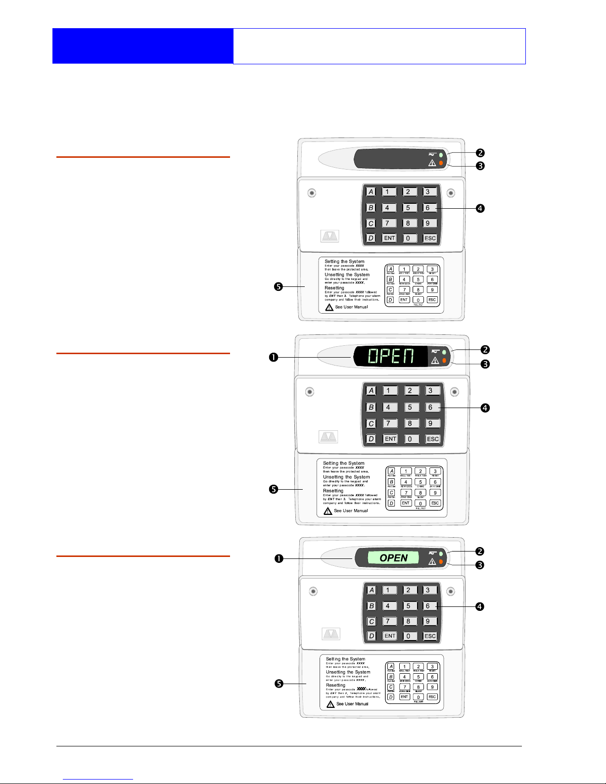
Remote Keypads
Your alarm system can be operated from
one or more remote keypads, which will
have been strategically located within the
protected premises.
Arming station
The remote arming
station can only be used
to set and unset the
alarm system.
LED Keypad
The LED remote keypad
can only be used to set
and unset the alarm
system.
Starburst Keypad
The Starburst remote
keypad can only be
used to set and unset the
alarm system.
Page 9
7
Overview
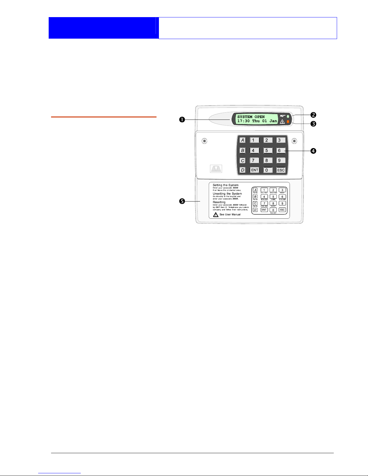
Remote Keypads
The LCD remote keypad is the only
keypad that will display full information.
Any kind of programming or testing of the
system, must be done using this type of
keypad.
LCD Keypad
The LCD remote keypad
is a full function keypad
and can be used to
program, test, set and
unset the alarm system.
This is the remote
keypad that is referred to
throughout this manual.
1. Display - Used to show the system
time (LED & Starburst), along with other
system messages (LCD only).
2. Green Power Indicator - Flashes if no
mains power is present. Steady when
mains power is present.
3. Red Function Indicator - Can be
programmed by the alarm company,
to indicate a fault, set or part-set etc.
4. Keyboard - Used for operating your
alarm system.
5. Cover - Fold-down cover with quick
guide operating instructions.
Page 10

8
Operation
Introduction
Passcodes
Access to the system is gained by
entering a 4 or 6 digit passcode. Every
time you wish to use the system your
passcode must be entered correctly.
User Types
The TS2500 can have up to 199 separate
users each user is assigned a passcode,
an access level and wards.
User Menus
The system has 4 users menus, with each
menu having between 9 and 12 options.
User menu 1 is accessed by entering your
passcode followed by the [ key. Access
to user menus and options will depend on
your user access level.
When a menu option is selected you may
abandon the option by pressing the ]
key. To leave the user menus and return
the system to its original state simply keep
pressing the ] key.
Banner Message
The banner message is normally shown
on the top line of display when the system
is unset or full set. This message is
configured by the installation engineer
and is usually set to the alarm company's
name.
Engineer on site
When your alarm company has an
engineer on site and is logged into the
system, the top line of keypads will show
"ENGINEER ON SITE". You can continue to
operate the system as normal, if required.
The message is automatically cleared
when the engineer logs off.
Page 11
9
Operation
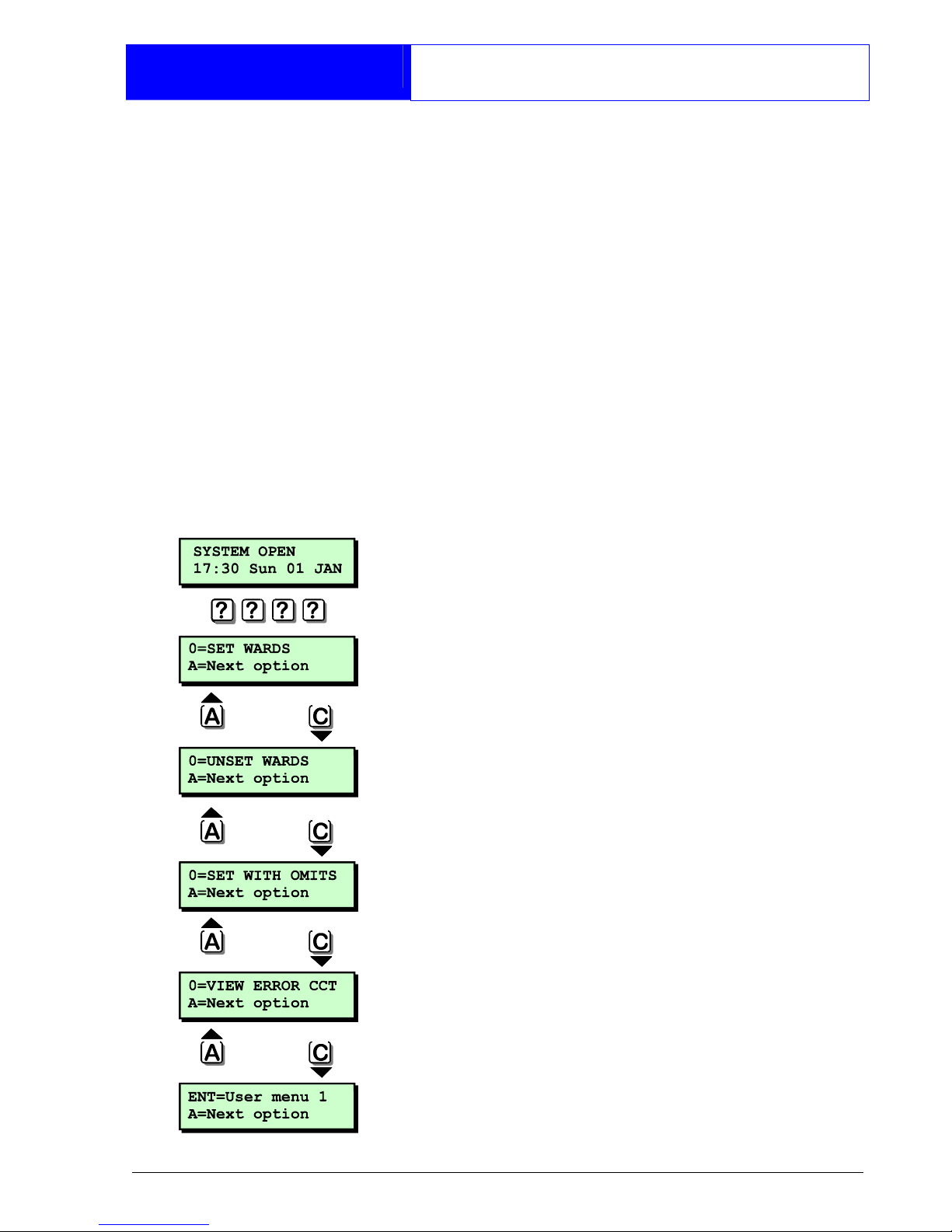
Using the Set/Unset Menu
The set/unset menu is displayed whenever
you enter your passcode. Pressing ]
whilst the menu is displayed will return the
system to its original state.
The set/unset menu has several options,
however, only options that are relevant will
be displayed, e.g. if all wards are unset,
the option to unset wards will not be
displayed.
You can scroll forwards through the
options by pressing the A key and
backwards by pressing the C key.
Set Wards
Pressing 0 will set your selected wards.
Pressing 8 will set your selected wards
silently.
Pressing B will allow you to access the
part set groups.
Unset Wards
Pressing 0 will unset your selected wards.
Set With Omits
Pressing 0 will set your selected wards
with pre-defined circuits omitted.
View Error Circuits
Pressing 0 will display the circuits that
prevented your wards from setting.
User Menu 1
Pressing [ will select user menu 1.
Page 12
10
Operation
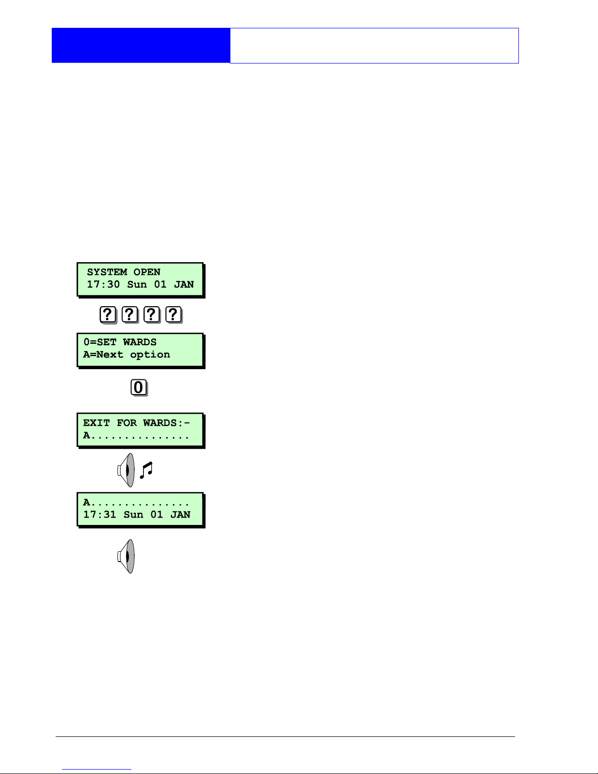
Setting Your Ward(s)
Setting of wards can only be performed
at a valid remote keypad. If you attempt
to set a ward from an invalid remote
keypad the display will show: Cannot 'SET'
from this keypad.
Before attempting to set your ward,
ensure all doors and windows are securely
closed and the wards to be protected are
vacated.
1. At the remote keypad enter your
passcode.
2. Press 0 to set your ward(s) or 8 to set
your wards silently.
3. Leave the area to be protected by the
designated exit route. The internal
sounder will sound.
4. Close the final door and press the exit
terminator button (if fitted).
5. When the internal sounder stops the
ward(s) is set.
If the exit tone changes to an alarm
tone, you must re-enter the protected
area and enter your passcode. The
display will show the ward(s) which failed
to set.
Page 13
11
Operation
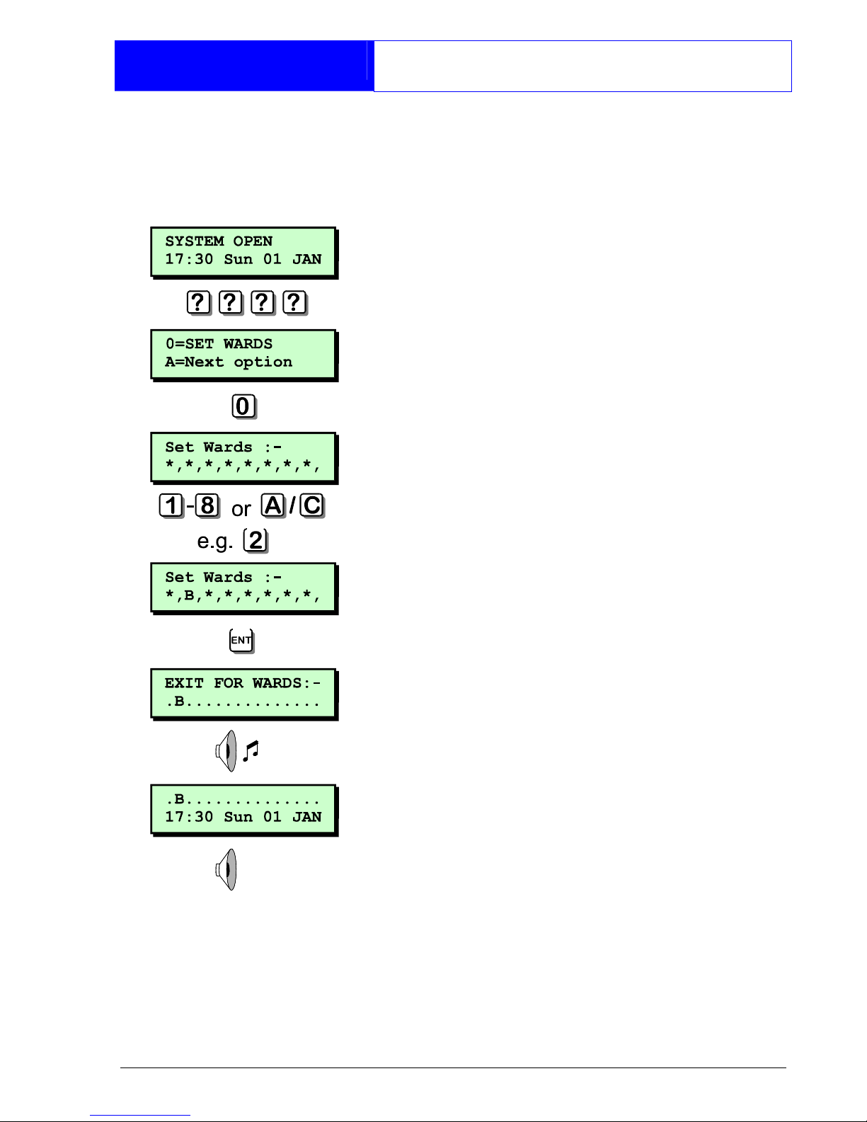
Setting Your Ward(s)
If your user code is assigned to more than
one ward, you may be able to select the
wards that you want to set after selecting
the SET WARDS option.
1. At the remote keypad enter your
passcode.
2. Press 0 to set your ward(s) or 8 to set
your wards silently.
3. Select wards by pressing 1 - 8,
pressing A or C will toggle the display
between wards A - H & wards I - P.
4. When the required wards are displayed
press [ to set them.
5. Leave the area to be protected by the
designated exit route. The internal
sounder will sound.
6. Close the final door and press the exit
terminator button (if fitted).
7. When the internal sounder stops the
ward(s) is set.
If the exit tone changes to an alarm
tone, you must re-enter the protected
area and enter your passcode. The
display will show the ward(s) which failed
to set.
Page 14
12
Operation
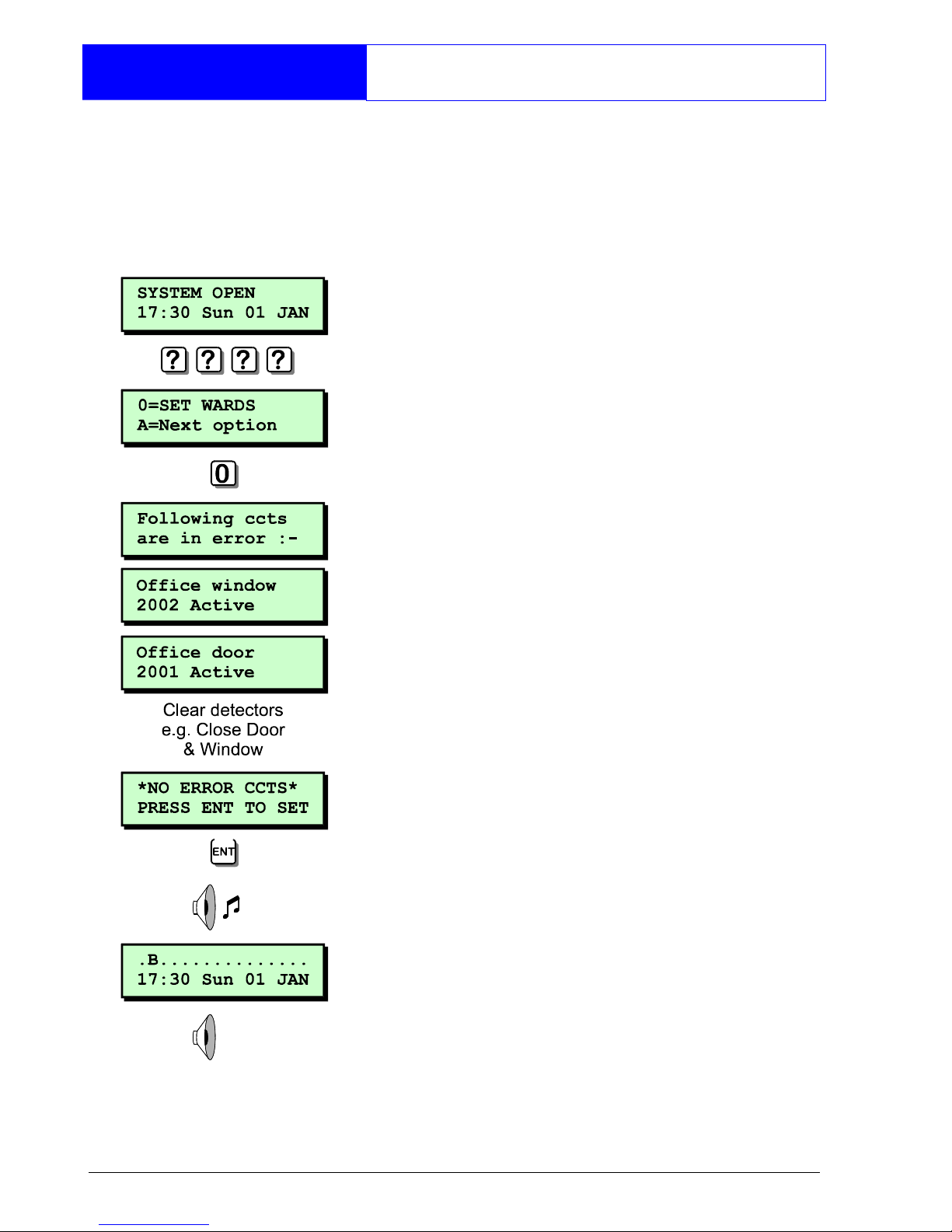
Setting with Circuits in Fault
When starting the exit procedure, any
active circuits, will cause the panel to
enter into a fault mode. Whilst in this
mode, the exit procedure is temporarily
suspended.
1. At the remote keypad enter your
passcode.
2. Press 0 to set your ward(s) or 8 to set
your wards silently.
3. The sounder will give a low fault tone
and the exit procedure will be
temporarily suspended, the display will
also automatically show all circuits that
are in fault. Pressing A or C will scroll
through these circuits.
4. Check the circuits displayed, when all
circuits show healthy, press [ to restart
the exit procedure.
5. Leave the area to be protected by the
designated exit route. The internal
sounder will sound.
6. Close the final door and press the exit
terminator button (if fitted).
7. When the internal sounder stops the
ward(s) is set.
This procedure is a programmable
option, and will only be displayed if
enabled by your installation company.
Page 15
13
Operation
Unsetting Your Ward(s)
Unsetting of wards can only be performed
at a valid remote keypad. If you attempt
to unset a ward from an invalid remote
keypad the display will show: Cannot
'UNSET' from this keypad.
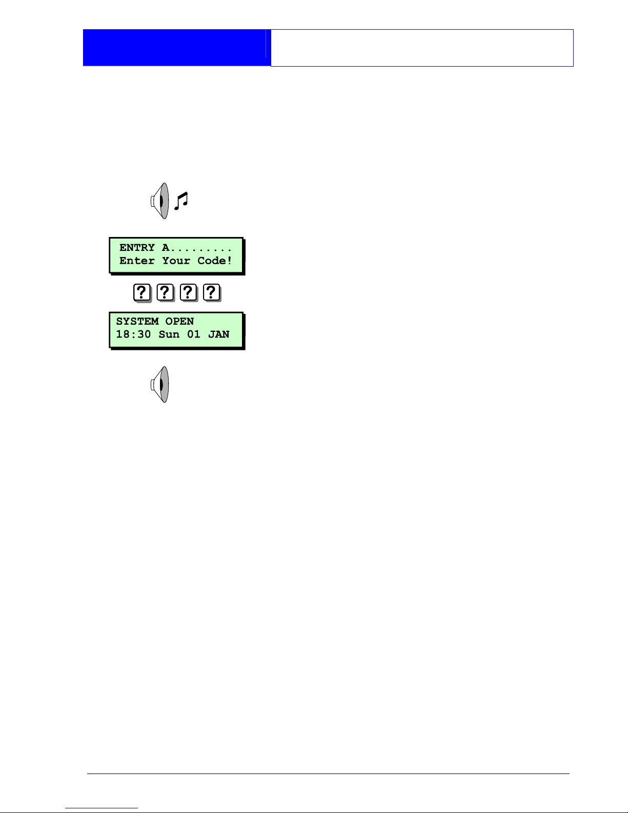
1. Enter the protected area via the
designated entry point, the internal
sounder will sound.
2. Proceed directly to the remote keypad
and enter your passcode. The internal
sounder will stop.
If your passcode is not entered before
the entry timer expires an alarm tone will
be generated from the internal sounders.
A second entry timer is then started. If you
fail to enter your passcode before the
second entry timer expires a full alarm
condition will occur.
Page 16

14
Operation
Unsetting Your Ward(s)
If your user code is assigned to more than
one ward you may be able to select the
wards that you want to unset.
1. Enter the protected area via the
designated entry point, the internal
sounder will sound.
2. Proceed directly to the remote keypad
and enter your passcode. The display
will show that the ward in entry is going
to be unset.
3. Select other wards by pressing 1 - 8,
pressing A or C will toggle the display
between wards A - H & wards I - P.
4. When the required wards are displayed
press [ to unset them. The internal
sounder will stop.
If your passcode is not entered or
[
is not pressed before the entry timer
expires an alarm tone will be generated
from the internal sounders.
A second entry timer is then started. If you
fail to enter your passcode or press
[
before the second entry timer expires a
full alarm condition will occur.
Page 17

15
Operation
Part Setting the System
The TS2500 can store up to 10 pre-
defined part set groups, each group is
allocated a combination of wards, e.g.
"PART SET GROUP 1" could be allocated
wards A and C, whereas "PART SET GROUP
2" could be allocated wards A and B etc.
1. At the designated remote keypad enter
your passcode.
2. Press B to select the PART SET GROUPS.
3. Select the group by pressing 1 - 9 or
0. As you press the keys the top line of
the display will show the group
description and the bottom line will
show the wards that will be set.
4. When you have the required group
displayed press [ to set the selected
group.
5. Leave the area to be protected by the
designated exit route. The internal
sounder will sound.
6. Close the final door and press the exit
terminator button (if fitted).
7. When the internal sounder stops the
ward(s) is set.
Page 18

16
Operation
Part Unsetting the System
The TS2500 can store up to 10 pre-
defined part set groups, each group is
allocated a combination of wards, e.g.
"PART SET GROUP 1" could be allocated
wards A and C, whereas "PART SET GROUP
2" could be allocated wards A and B etc.
1. At the designated remote keypad enter
your passcode.
2. Press B to select the PART SET GROUPS.
3. Select the group by pressing 1 - 9 or
0. As you press the keys the top line of
the display will show the group
description and the bottom line will
show the wards that will be unset.
4. When you have the required group
displayed press [ to unset the
selected group.
Page 19

17
Operation
Setting with Circuits Omitted
If you have configured the alarm system
to omit one or more circuits, you may set
your wards with those circuits omitted. For
details on selecting the circuits to be
omitted, see "Omitting Circuit" on page
29. If no circuits are selected the option to
"SET WITH OMITS" will not appear in the
set/unset menu.
1. At the remote keypad enter your
passcode.
2. Press 0 to set with circuits omitted. If
you want to set without circuits omitted,
press the A key until the display shows
"0 = SET WARDS".
3. Leave the area to be protected by the
designated exit route. The internal
sounder will sound.
4. Close the final door and press the exit
terminator button (if fitted).
5. When the internal sounder stops the
ward(s) is set and the selected circuits
are omitted.
If the exit tone changes to an alarm
tone, you must re-enter the protected
area and enter your passcode. The
display will show the wards which failed to
set.
When you unset the ward(s) make sure all
previously omitted circuits are armed
before setting the system again, see
"Omitting Circuits" on page 29.
Page 20
18
Operation
Viewing Error Circuits
If during the setting procedure one or more
circuits remain active, the alarm system will
fail to set. The internal sounder will sound
and the external strobe will flash.
Before the alarm system can be
successfully set you must ensure that the
circuits that caused the "SET FAIL" condition
are healthy.
The following procedure describes how to
view the circuits that cause the "SET FAIL"
condition, so that you can check and
rectify the faults. Once rectified you should
be able to successfully set your wards.
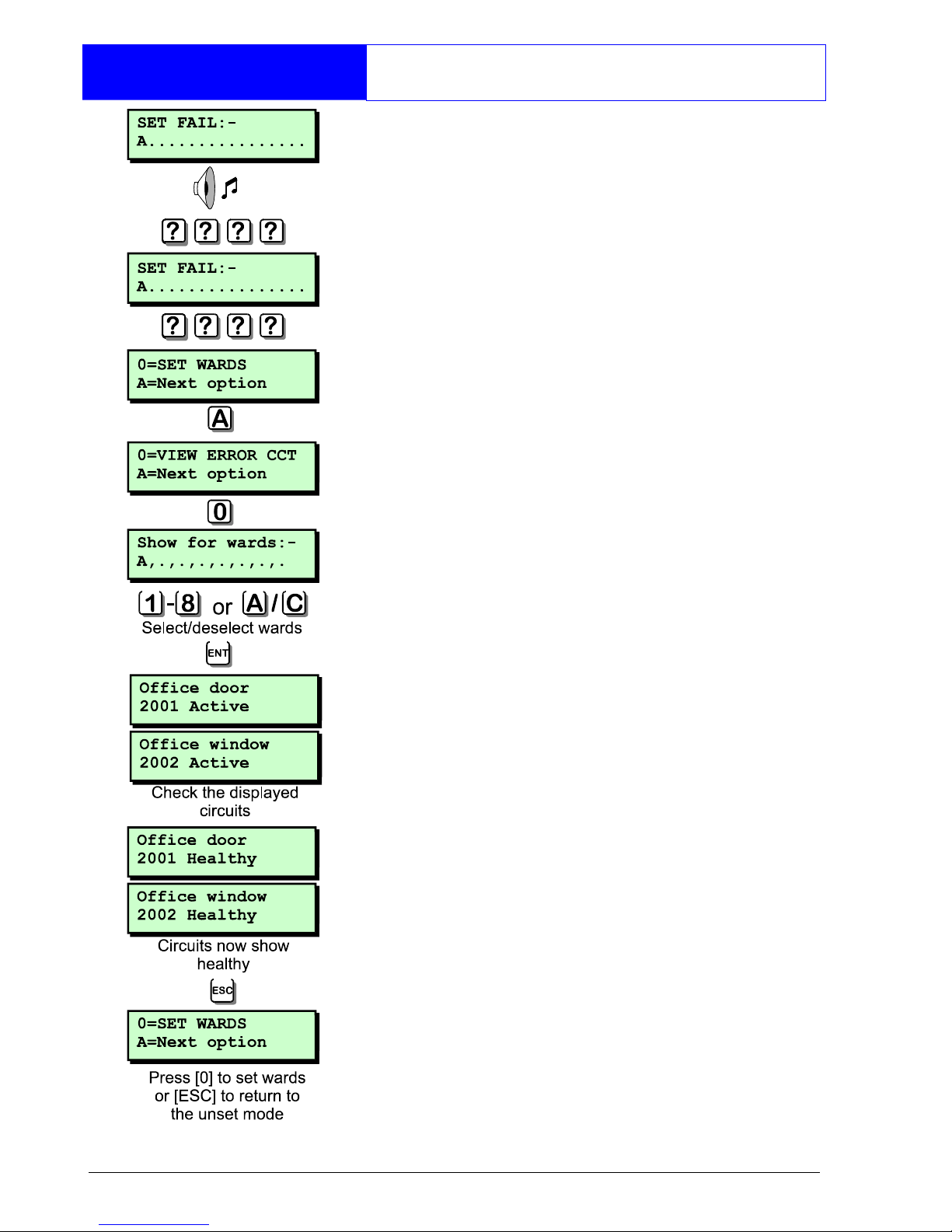
From a "SET FAIL" condition:
1. Re-enter the protected area and
proceed directly to the remote keypad.
2. Enter your passcode, the display will show
which ward failed to set.
3. Enter your passcode and press A until
the display shows "0=VIEW ERROR CCT".
4. Press 0 the display will prompt you to
select which wards you want to check.
5. To select or deselect wards A- H press 1
- 8. To select or deselect wards I - P
press A then 1 - 8.
6. Check the displayed circuits, when all circuits
show healthy you are ready to set.
7. Press ] and press 0 to set your wards.
Page 21

19
Operation
Unsetting after an Alarm
If an alarm has occurred whilst the
system was set, the display will indicate
the cause of the alarm when you unset
the system. Once the cause of the alarm
has been established the system must be
reset, see "Resetting after an Alarm" on
page 20.
1. Enter the protected area via the
designated entry point. The internal
sounder will sound.
2. Proceed directly to the remote keypad
and enter your passcode. The internal
sounder will stop.
3. The display will show the circuit that
caused the alarm.
4. By pressing the B key the display will
alternate between the circuit text, e,g.
Office window and the logged
time/date of the alarm, e.g. 15:00.30
01/01.
5. The system now requires resetting.
If the alarm system is not reset after
an alarm has occurred the internal
sounder will generate a reset warning
chime every minute as a reminder. To
silence this tone simply re-enter your
passcode.
Page 22

20
Operation
Resetting after an Alarm
Each ward can be configured to be reset
by one of the following methods:
User Reset
Full alarms generated in a ward that is
configured as user reset can be reset by
any user that has access for that ward.
From step 5 of "Unsetting after an Alarm":
1. At the designated remote keypad enter
your passcode.
2. Press ].
3. Your ward(s) is now reset.
Engineer Reset
Full alarms generated in a ward that is
configured as engineer reset can only be
reset by the engineer.
From step 5 of "Unsetting after an Alarm".
1. At the designated remote keypad enter
your passcode. This will silence the reset
warning chime.
2. Every minute the display will inform you of
the action to take (normally "CALL
ENGINEER TO RESET SYSTEM" although
your alarm company can change this
to more relevant information).
3. Contact your alarm company.
Page 23
21
Operation
Resetting after an Alarm
Remote Reset
Full alarms generated in a ward that is
configured as remote reset can be reset
by the engineer or the user via the
exchange of unique passcodes.
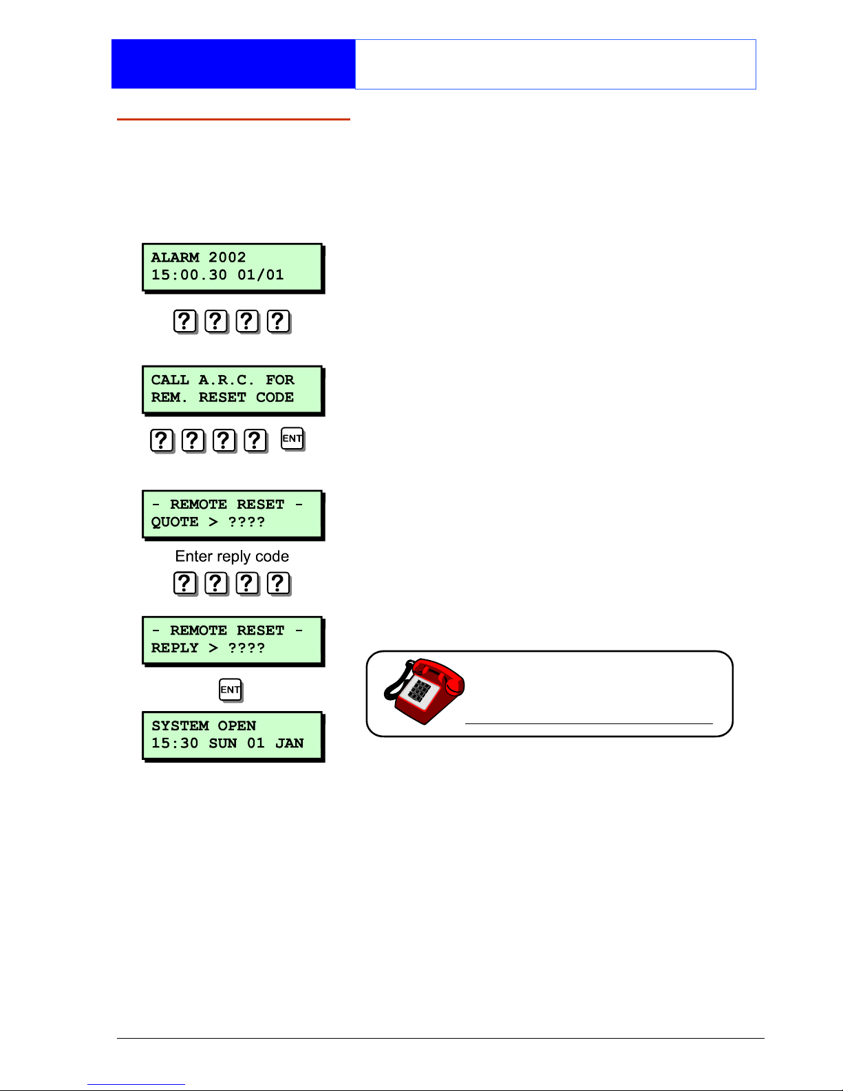
From step 5 of "Unsetting after an Alarm".
1. At the designated remote keypad enter
your passcode.
2. Every minute the display will inform you
of the action to take (normally "CALL
A.R.C FOR REM. RESET CODE", although
your alarm company can change this
to more relevant information).
3. Enter your passcode followed by the [
key.
4. The display will advise you of the
number to quote to your alarm
receiving centre.
5. Contact your alarm receiving centre.
6. You will be asked to report the
circumstances of the alarm. If the
alarm receiving centre decides you do
not require an engineer, a 4 digit
remote reset code will be given to you.
7. Enter the 4 digit remote reset code
followed by the [ key and the system
will return to its normal condition.
Page 24

22
User Menu 1
Introduction
User menu 1 is accessed by entering
your passcode followed by [ There are
9 menu options and access to these
options will depend on your access level.
Each option has a "hotkey" and can be
selected by pressing the relevant
number, e.g. "Do Walk Test" is assigned to
key 2, so to select the weak test option
press 2 followed by [.
Alternatively you can use the A & C
keys to scroll forwards and backwards
through the available options. As you
press the A & C keys the bottom line of
the display will show the selected menu
option. When you have found the
required option press the [ key to
perform the option.
To leave user menu 1 and return the
system to its original state simply keep
pressing the ] key until the display shows
the time and date.
Page 25
23
User Menu 1
Testing Bells & Sounders
This option allows you to periodically test
the external sounders (bell and strobe)
and internal sounders.
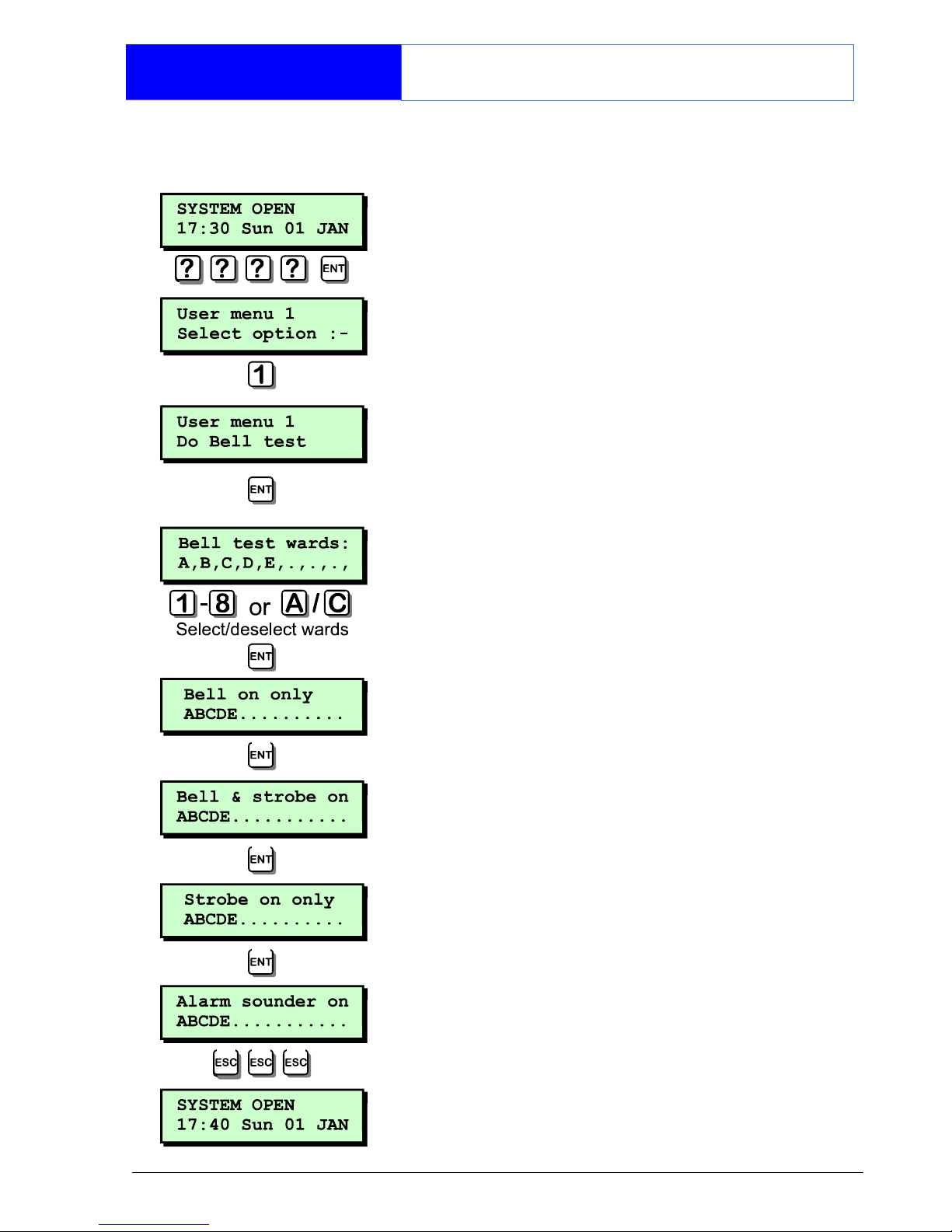
1. At the remote keypad enter your
passcode followed by [.
2. Press 1 followed by [ to select the
bell test option.
3. The display will show which wards are
selected for bell test.
4. To select or deselect wards A - H press
1 - 8. To select or deselect wards I - P
press then 1 - 8.
5. Once you have the required wards
selected press [ to start the test.
6. The external sounder is active. Press [
for next test or ] to end.
7. The external sounder & strobe is active.
Press [ for next test or ] to end.
8. The strobe is active. Press [ for next
test or ] to end.
9. The internal alarm sounder is active.
Press [ to repeat all tests or ] to end.
10. Press ] twice to return the system to its
original state.
Page 26
24
User Menu 1
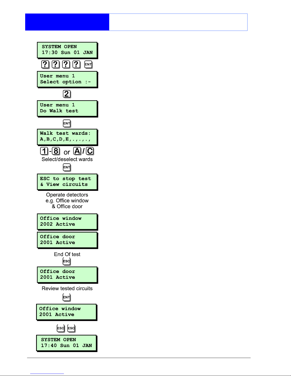
Walk Testing Circuits
This option allows you to periodically test
the operation of detection circuits. You
can only select or deselect the wards
that you have access to.
1. At the remote keypad enter your
passcode followed by [.
2. Press 2 followed by [ to select the walk
test option.
3. The display will show which wards are
selected for walk test.
4. To select or deselect wards A - H press 1
- 8. To select or deselect wards I - P press
A then 1 - 8.
5. Once you have the required wards
selected press [ to start the test.
6. Walk around the wards that are being
tested and operate all detection devices.
As each device is operated there will be a
chime tone from the internal sounders and
the display will show the triggered circuit.
7. When finished press ]. Pressing [ will
allow you to scroll through the tested circuits
in a chronological order. Press ] twice
times to return the system to its original
state.
Page 27

25
User Menu 1
Use Remote Reset
The remote reset option allows you to
reset your alarm via the exchange of
unique passcodes.
The remote reset procedure is fully
covered on page 17.
If you select this option when the system
does not require resetting the display will
show "Remote reset is not required".
Page 28
26
User Menu 1
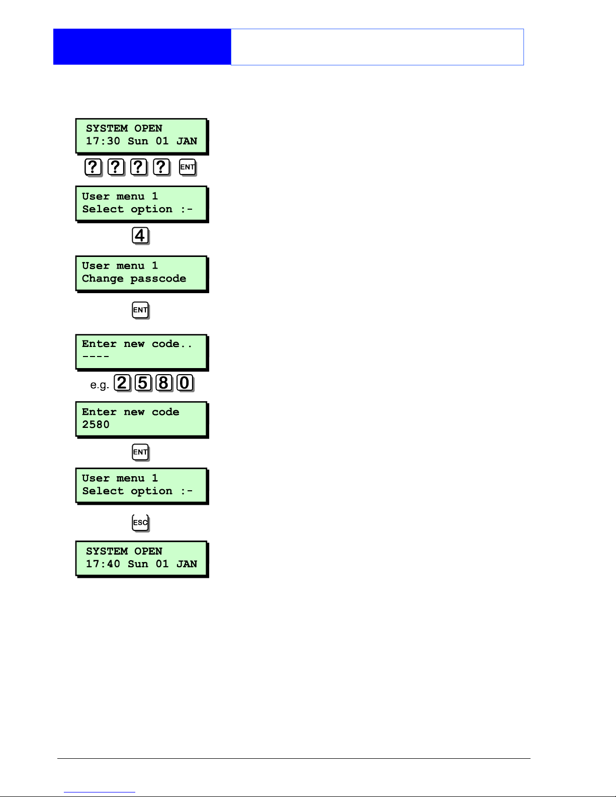
Changing Your Passcode
This option allows you to change your
own passcode.
1. At the remote keypad enter your
passcode followed by [.
2. Press 4 followed by [ to select the
change passcode option.
3. Enter your new passcode followed by
[.
4. If your new code is not accepted the
display will show "NOT ACCEPTED try a
different code".
5. Press ] to return the system to its
original state.
If your system has been configured to
use 6 digit passcodes, the last two digits
of the passcode will always be the last
two digits of your user number, i.e. if you
are user 001. Your passcode will be
????01. If you are user 002, your
passcode will be ????02 etc.
Page 29
27
User Menu 1
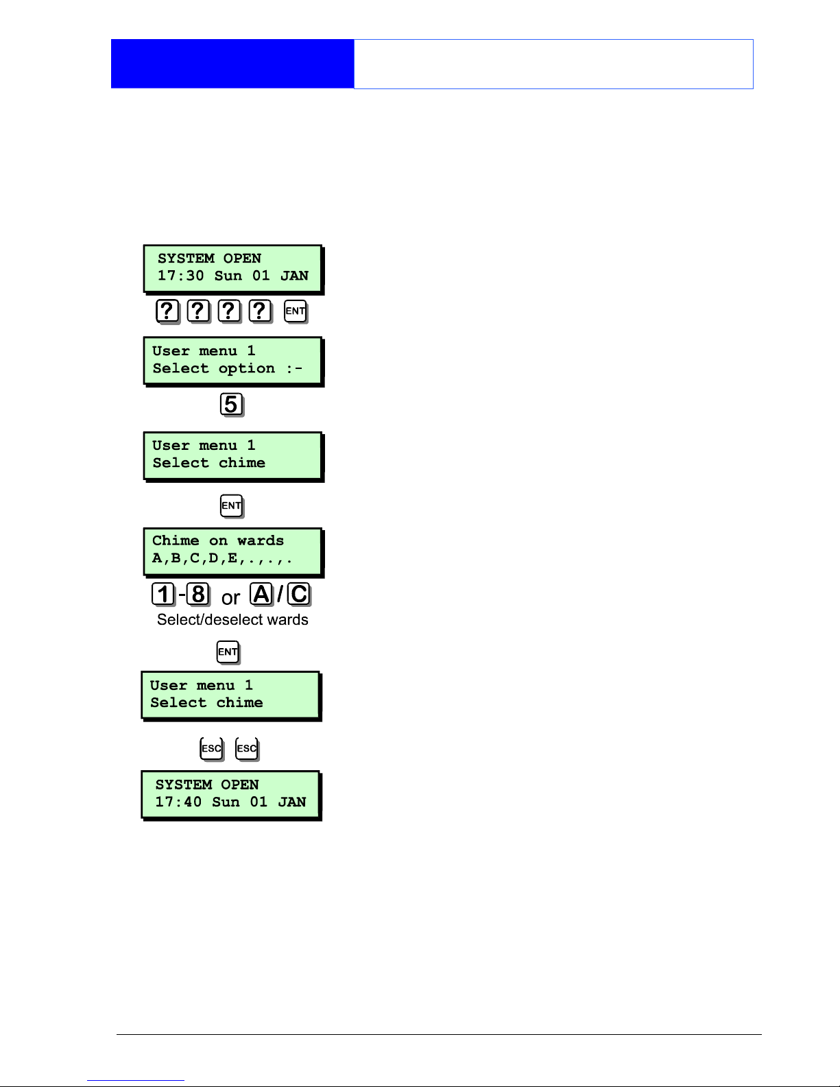
Selecting Chime
This option allows you to enable or
disable the chime feature for your wards.
If a ward has the chime feature enabled,
detection circuits that have been
programmed as "Chime" will generate a
chime tone when activated.
1. At the remote keypad enter your
passcode followed by [.
2. Press 5 followed by [ to select the
chime option.
3. The display will show which wards are
currently selected for chime.
4. To select or deselect wards A - H press
1 - 8. To select or de-select wards I P press A then 1 - 8.
5. Once you have the required wards
selected press [ to accept.
6. Press ] twice to return the system to its
original state.
Page 30
28
User Menu 1
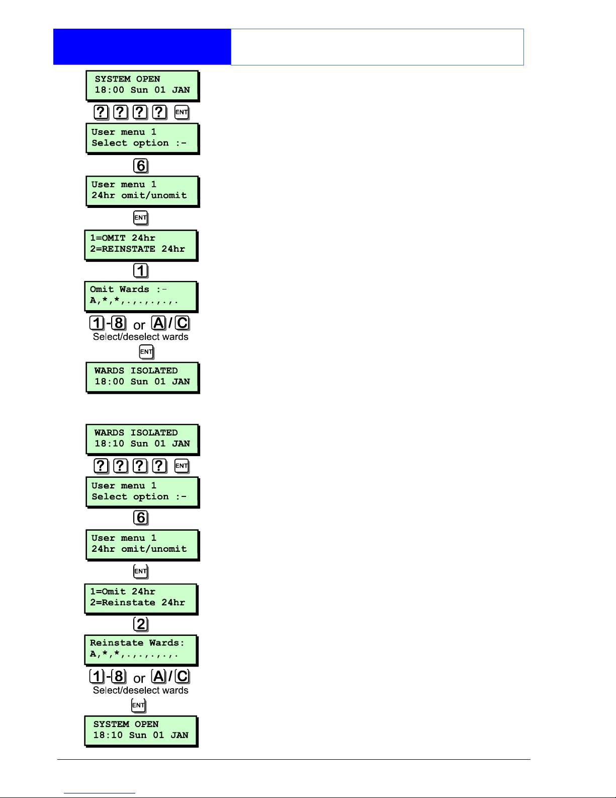
Omitting a 24hr Group
This option allows you to omit a group of
24hr detection circuits. The group is predefined by the master user or alarm
company.
1. At the remote keypad enter your
passcode followed by [.
2. Press 6 followed [ to select the 24hr
omit option.
3. Press 1 to select omit wards. To select
or deselect wards A - H press 1 - 8.
To select or deselect wards I - P press
A then 1 - 8.
4. When the required wards are displayed
press [ to accept. The system will
automatically return to the unset
condition and the display will show
"WARDS ISOLATED! indicating that one or
more 24hr circuits within the selected
wards are isolated.
5. To reinstate the 24hr group repeat steps
1 to 4, except press 2 at step 3.
Page 31
29
User Menu 1
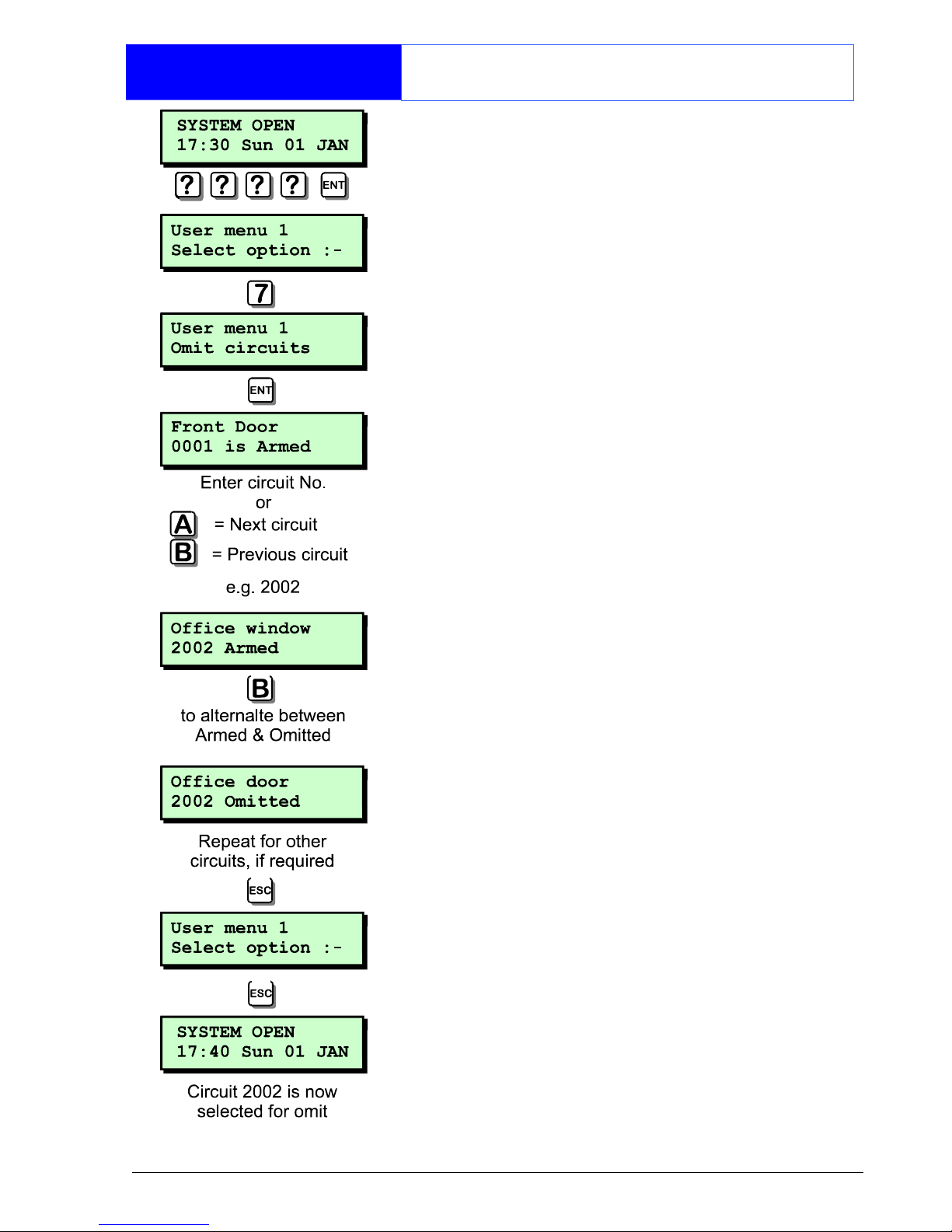
Omitting Circuits
Occasionally it may be necessary to omit
detection circuits when setting your ward,
e.g. to leave door open that would
normally be protected. This option allows
you to select which circuits are to be
omitted.
Once selected you can then choose to
set your ward(s) with or without the
selected circuits omitted, see "Setting
With Omits" on page 17.
1. At the remote keypad enter your
passcode followed by [.
2. Press 7 followed by [ to select the
omit circuits option.
3. The display will show circuit 0001 and its
current omit status.
4. Select the circuit you require to omit by
either entering its number or by pressing
the A & C keys to scroll up and down
through the circuits.
5. When the display shows the required
circuit, press B to alternate the circuit
between armed and omitted.
6. Repeat steps 4 and 5 for other circuits,
if required.
7. When finished, press ] to return the
system to its original state.
Page 32

30
User Menu 1
Silent Set Wards
This option allows you to configure which
wards will set silently, i.e. no exit tone
when setting the selected ward. The
wards that you select will remain
configured as "silent set" until you
deselect them using this menu option.
1. At the remote keypad enter your
passcode followed by [.
2. Press 8 followed by [ to select the
"Silent set wards option".
3. The display will show which wards are
currently selected for silent set.
4. To select or deselect wards A - H press
1 - 8. To select or deselect wards I - P
press A then 1 - 8.
5. Once you have the required wards
selected press [ to accept.
6. Press ] twice to return the system to its
original state.
Your selected wards will now set silently.
Pressing
8 when the display shows
"0 = SET WARDS" will also set all your
wards silently.
Page 33

31
User Menu 1
Set/Unset Menu
Normally the set/unset menu is displayed
whenever you enter your passcode. This
option allows you to access the menu
whilst user menu 1 is selected.
The set/unset menu has several options,
however, only options that are relevant
will be displayed, e.g. If all wards are
unset, the option to unset wards will not
be displayed.
Set Wards
Pressing 0 will set your selected wards.
Pressing 8 will set your selected wards
silently.
Pressing B will allow you to access the
part set groups.
Unset Wards
Pressing 0 will unset your selected
wards.
Set With Omits
Pressing 0 will set your selected wards
with pre-defined circuits omitted.
View Error Circuits
Pressing 0 will display the circuits that
prevented your wards from setting.
User Menu 1
Pressing [ will select User menu 1.
Page 34

32
User Menu 1
Selecting User Menu 2
User menu 2 is accessed by pressing [
whilst "User menu 1 Select option :-" is
displayed.
To leave user menu 2 and return to user
menu 1 simply press the ] key.
This manual does not cover the
procedures available in user menu 2. For
full details of user menus 2, 3 and 4
please refer to the "Managers Operating
Manual".
Page 35

33
Fault Finding
Display Messages
Unset alarms & Faults
These messages can occur when your ward is
unset, if accompanied with an internal alarm
they can be silenced by entering your
passcode.
Your alarm system is fitted with a remote
signalling device which is reporting a telephone
line fault. If the fault is not Cleared you may not
be able to set your ward. If the fault persists.
Contact your alarm company for further
advice.
There is no mains power to the control panel
and the alarm system is now running on its
standby battery. If the mains power is not
restored you may not be able to set your ward,
if the fault persists the standby battery will
eventually run flat. Contact your alarm
company for further advice.
The alarm system standby battery has
developed a fault. If the fault is not cleared you
may not be able to set your ward. Contact
your alarm company for further advice.
The lid of the control panel has been removed.
If the fault is not cleared you may not be able
to set your ward. Contact your alarm company
for further advice.
The control panel has two auxiliary tamper
circuits for monitoring auxiliary devices. The lid
of the device has been removed. If the fault is
not cleared you may not be able to set your
ward. Contact your alarm company for further
advice.
The lid of the external sounder has been
removed. If the fault is not cleared you may
not be able to set your ward. Contact your
alarm company for further advice.
The auxiliary supply used for powering
detection devices has blown its fuse. Contact
your alarm company for further advice.
Page 36
34
Fault Finding
Display Messages
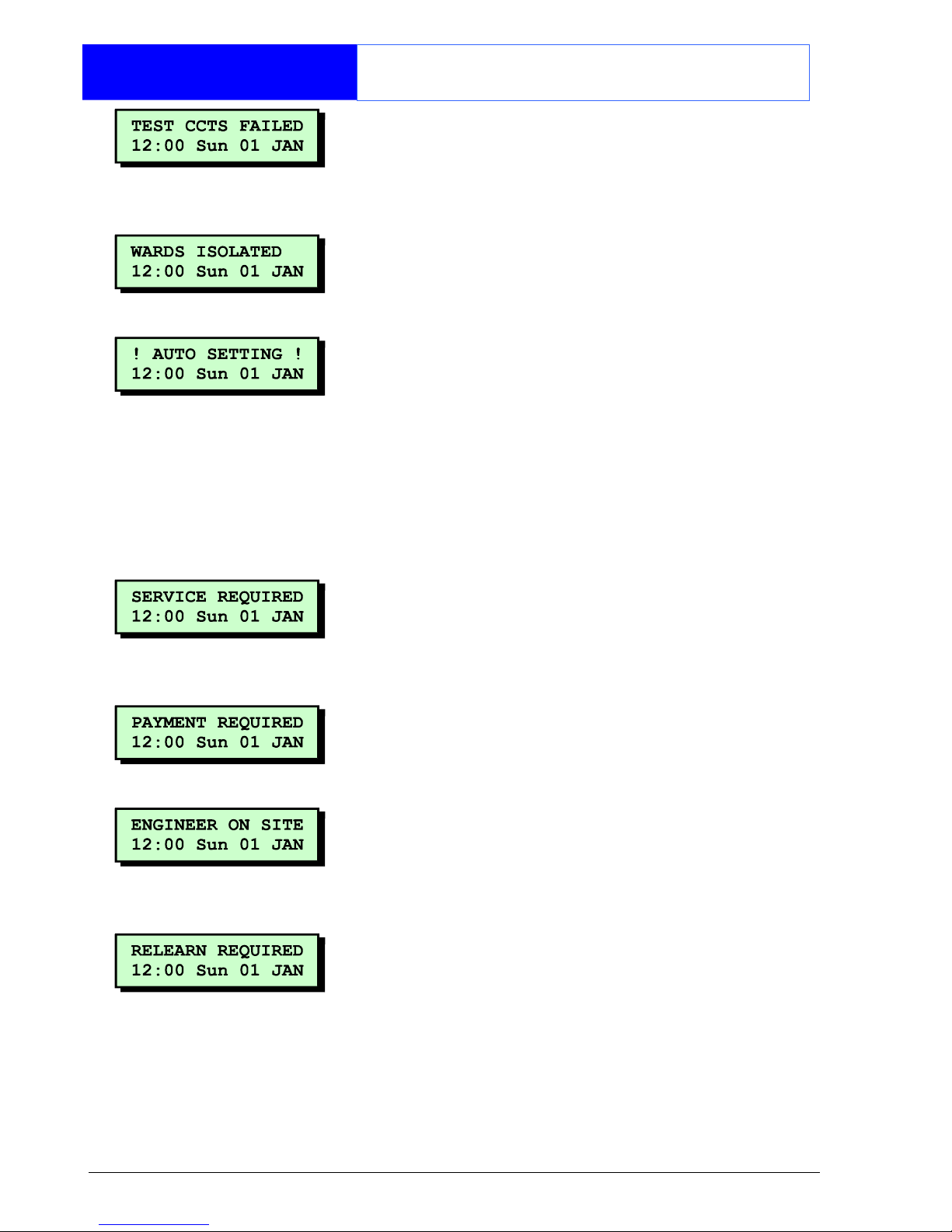
One or more circuits have failed during a test
routine initiated by your alarm company. You
can still set and unset your wards but you
should contact your alarm company for further
advice.
One or more wards have been isolated so that
24hr protection with those wards can be
accessed. Press [ to display which wards are
currently isolated.
The TS2500 has an auto-set feature which will
automatically set and unset specified wards at
pre-programmed times, This message is
displayed one minute before the wards are
due to set and a chime tone is generated
every ten seconds to warn you to leave the
area. If you have the appropriate access code
you can defer the automatic setting by
entering your passcode and choosing the
"DEFER SETTING" option.
The alarm system requires a routine
maintenance visit from your alarm company.
You can still set and unset your wards but you
should contact your alarm company for further
advice.
Your alarm company has enabled the
payment timer and the timer has expired. You
cannot set your wards and should contact your
alarm company for further advice.
Your alarm company has had an engineer on
site and is logged into the alarm system. You
can continue to operate the system as normal,
if required. The message is automatically
cleared when the engineer logs off.
The hardware configuration of your alarm
system has changed. You may not be able to
set your wards and should contact your alarm
company for further advice.
Page 37

35
Fault Finding
Display Messages
Another user is accessing the alarm system.
You cannot use your keypad until this message
has cleared.
The TS2500 has an high security feature which
can be applied to any ward. When the ward is
unset the remote keypads display "HI SECURE
UNSET" and the high security timer is started.
Every time a detection device is triggered
within the selected ward the timer is reset.
However, if no detection devices within the
selected ward are triggered, the timer will
eventually expire. When the timer expires the
ward is automatically set and the message on
the keypads is cleared.
This message is displayed whenever a keypad
is locked out because there has been too
many invalid code entries. This message will
clear and the keypad will unlock itself after 5
minutes.
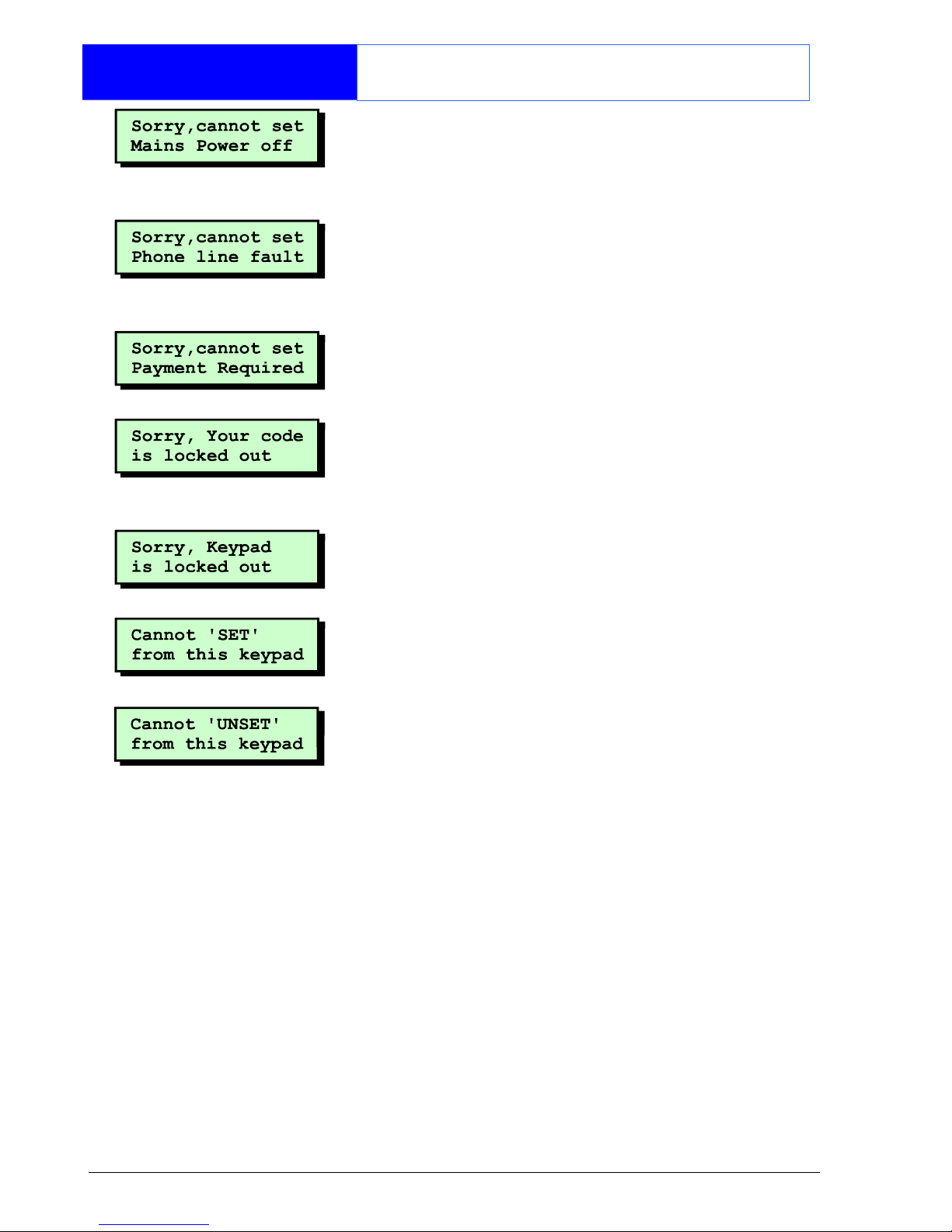
Cannot Set
Messages
These messages occur when the system is
unable to set your selected wards.
Cannot set due to a tamper fault on auxiliary
circuit 1 or 2. Clear the fault and if still
displayed contact your alarm company for
further advice.
Cannot set due to a tamper fault on the
external sounder. Clear the fault and if still
displayed contact your alarm company for
further advice.
Cannot set due to a fault from one or more
system components. The display will indicate
the faulty device. Clear the fault and if still
displayed contact your alarm company for
further advice.
Cannot set due to a fault from one or more
circuits. The display will indicate the faulty
circuits. Clear the fault and if still displayed
contact your alarm company for further
advice.
Cannot set due to a tamper fault on the
control panel. Clear the fault and if still
displayed contact your alarm company for
further advice.
Page 38
36
Fault Finding
Display Messages
Cannot set due to no mains power at the
control panel. Clear the fault and if still
displayed contact your alarm company for
further advice.
Cannot set due to a phone line fault from your
remote signalling device. Clear the fault and if
still displayed Contact your alarm company for
further advice.
Cannot set due to the expiry of the payment
timer. Contact your alarm company for further
advice.
The TS2500 has a code lock feature which can
be applied to selected users. When the code
lock is in operation the selected users cannot
use their passcode to set or unset their wards.
The remote keypad is locked out and cannot
be used by any users. The lock out is normally
controlled by a key switch or similar.
The remote keypad that you are using to set
from is not assigned to your wards. Use a
remote keypad that is assigned to your wards.
The remote keypad that you are using to unset
from is not assigned to your wards. Use a
remote keypad that is assigned to your wards.
Page 39

37
Records
System Details
Wards
Setting
A B C D E F G H
Entry Time
Exit Time
Setting
Mode
Bell Delay
Bell Time
User Reset
Eng. Reset
Rem. Reset
Wards
Setting
I J K L M N O P
Entry Time
Exit Time
Setting
Mode
Bell Delay
Bell Time
User Reset
Eng. Reset
Rem. Reset
Set with Line Fault Set with Mains Off
4 or 6 digit passcode Automatic Omitting
Remote Signalling Downloading
Page 40

38
Records
User Details
No. Name Type Wards Auto-set Auto-Unset
000 Engineer A - P A A
001 Master
Page 41

39
Records
User Details
No. Name Type Wards Auto-set Auto-Unset
Page 42

40
Records
Circuit Details
No. Location Omit Chime Wards
Page 43

41
Records
Circuit Details
No. Location Omit Chime Wards
Page 44

42
Records
Circuit Details
No. Location Omit Chime Wards
Page 45

43
Records
Circuit Details
No. Location Omit Chime Wards
Page 46

44
Records
Service Record
Date Engineer Action
Page 47

45
Records
Installer Information
Installation Engineer:
Installation Company:
Address:
Telephone No:
Reset Message:
Alarm Receiving Centre:
Telephone No:
Rem. Reset Message:
Page 48

Part No. 496496 Issue 2
 Loading...