

Page 1
Installation and User Instructions and Systems Log
Menvier Fire System
MF9300
Eight and sixteen zone control panels
Page 2

IMPORTANT
THIS MENVIER FIRE PANEL IS DESIGNED TO BE USED WITH POLARISED AND
SUPPRESSED BELLS. DO NOT USE WITH UNSUPPRESSED BELLS, UNSUPPRESSED
RELAYS OR NON-POLARISED SOUNDERS OR STROBES ETC. DO NOT CONNECT 230V
MAINS DIRECTLY TO THE PCB. ELECTRICAL INSULATION TESTS SHOULD NOT BE
CARRIED OUT WITH THE CABLES CONNECTED TO THE PANEL OR DETECTORS OR
SOUNDERS.
BEFORE MOUNTING THE PANEL PLEASE CARRY OUT THE FOLLOWING TEST:
CONNECT ALL END OF LINE RESISTORS TO ZONE AND ALARM LINE TERMINALS
(SEE FIG. 3 PG. 27). CONNECT A MAINS SUPPLY,THAT IS NOT SWITCHED ON, TO THE
PANEL. SCREW THE CENTRE SECTION INTO PLACE ON THE BACK BOX. CONNECT THE
BATTERIES AND THEN SWITCH ON THE MAINS SUPPLY.
CHECK THAT ALL LIGHTS EXTINGUISH APART FROM THE POWER ON LIGHT. SELECT
LAMP TEST AND CHECK THAT ALL LAMPS LIGHT AND THE INTERNAL BUZZER
SOUNDS. IF ANY FAULT EXISTS THEN PLEASE CONTACT THE MENVIER SALES OFFICE.
ACCESSORIES
MBG913 Flush Mounting Call Point
MBG914 Surface Mounting Call Point
MBG917 Weatherproof Call Points
MMT760 Medium Response Heat Detector
MHT790 High Temp. Response Heat Detector
MFR730 Fast Response Heat Detector
MID710 Ionisation Smoke Detector
MDP720 Photoelectric Smoke Detector
MDB700 Common Detector Base
MBB244 4ins (100mm) Bell
MBM246 6ins (150mm) Bell
MBM248 8ins (200mm) Bell
MWB824 8ins (200mm) Weatherproof Bell
MDS724 Ceiling Sounder
MFS324 Flush Sounder
MWS424/DB Weatherproof Sounder - Deep Base
MWS424/SB Sounder - Shallow Base
MCD524/DB Combined Sounder/Beacon - Deep Base
MCD524/SD Combined Sounder/Beacon - Shallow Base
MXB124/DB Xenon Beacon - Deep Base (1W)
MXB124/SB Xenon Beacon - Shallow Base (1W)
MXB224/DB Xenon Beacon - Deep Base (2W)
MXB224/SB Xenon Beacon - Shallow Base (2W)
MAS175 Discrete Sounder/Indicator
MAR724 Heavy Duty Replay
Page 3
IMPORTANT NOTICE RELATING TO INSTALLING AND
SER VICING THE P ANEL
WHENEVER POWERING UP THE PANEL FROM A COMPLETELY POWERED
DOWN STATE,
I.E. NO MAINS OR BATTERY SUPPLY CONNECTED, THE SYSTEM RESET
BUTTON MUST BE PRESSED - SEE FIG. 2 FOR THE LOCATION OF THIS
PUSH BUTTON.
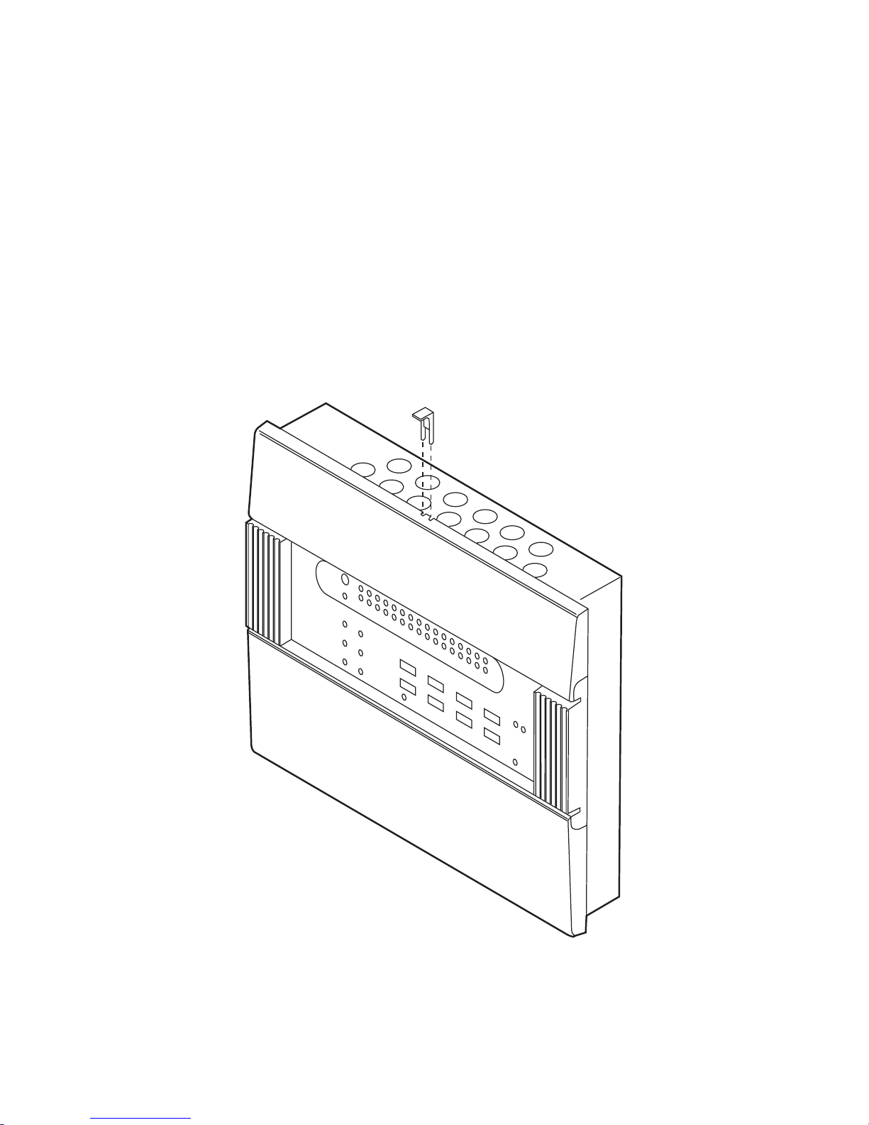
PLEASE ALSO NOTE THAT ACCESS TO THE SERVICE AREA, BEHIND THE
UPPER DOOR, SHOULD BE GAINED BY USING THE SPECIAL FORKED KEY
PROVIDED. INSERT THE KEY AS SHOWN BELOW, PRESS DOWN AND THE
DOOR LATCH WILL CLEAR ALLOWING THE DOOR TO BE OPENED.
ATTEMPTING TO GAIN ENTRY TO THE SERVICE AREA WITH-
OUT USE OF THE KEY MAY DAMAGE THE PANEL.
Page 4

TABLE OF CONTENTS
ACCESSORIES 1
OVERVIEW 4
SYSTEM OPERATION 4
OPERATING THE PANEL 5
SPECIALISED OPTIONS 8
APPENDIX A
Fire Alarm Log 9
Details Of Installation 18
Details Of Modifications 19
APPENDIX B
Faults - How To Recognise Them & What Action To Take 20
Fires - How To Recognise Them 20
APPENDIX C
Installation Of The MF9308 Control Panels 21
Using The Panel Interfaces 22
Setting System Parameters 24
APPENDIX D
Assembly Drawing 25
Positional Layout of Components 26
Wiring Diagram 27
Technical Specifications 28
PAGE 3
Page 5

OVERVIEW
This document gives details of how to install, test, use and maintain operation of your MF9300 fire
alarm panel.
SYSTEM OPERATION
What To Do At A Glance
The following information tells you what the various indicators, visible on the front panel, mean and
how you should react to them.
INDICATOR STATUS ACTION
GENERAL FIRE ON Fire detected alarms not sounded.
FLASHING Fire detected alarms sounded.
ALARM LINE DELAY ON No action. Alarm line delays are set
up.
FLASHING Fire has been detected. Alarm delay
is in action, check for fire.
SYSTEM FAULT ON Refer to service provider (see front of
this manual for telephone number)
DISABLEMENT FLASHING No action. Zone(s) disabled.
TEST FLASHING Zone in test. If service provider is on
site take no action. Else refer to
service provider (see front of this
manual for telephone number).
REMOTE SIGNAL ISOLATE ON No action. Remote signal output is
isolated.
SUPERVISOR MODE ON No action - you are in Supervisor
mode - see section on `Operating
The Panel`.
FLASHING No action. System is self-checking.
Indicator should go out within 25
seconds.
GENERAL FAULT FLASHING Refer to Appendix B
PAGE 4
Page 6

OPERA TING THE P ANEL
General
The panel operates in 1 of 2 modes - Normal mode or Supervisor mode. In Normal mode the
Supervisor mode LED is extinguished. In Supervisor mode the Supervisor LED is continuously ON.
Control of the facilities at the panel is available via the keyboard. Akey press is acknowledged by a
blip of the internal panel buzzer. All keys that are active in the Normal mode have their legend actually on the key itself, whereas all those facilities that are active once in the Supervisor mode have their
legends above the corresponding key. For example, in Normal mode pressing the SILENCE BUZZER
key will silence the internal panel buzzer. However, if in the Supervisor mode pressing the same key
will perform a Lamp Test.
Normal Mode
This is the condition the panel is generally to be found in. From the Normal mode the user may:
Silence Buzzer:
The user can silence the panel buzzer by pressing the SILENCE BUZZER button on the
keyboard. The buzzer will then only sound approximately once every 10 seconds. NOTE
that this does not silence any alarms, only the buzzer within the panel.
Entering the Supervisor mode:
By entering a 4 digit access code the user may get into the Supervisor mode. The access
code for this panel is 2214. By pressing the numbered keys in the correct order, and then by
hitting the ENTER key, the user will see the Supervisor mode indicator come on. Note that
the buzzer will sound when it has recognised each key press. You are then in the Supervisor
mode and may carry out additional facilities at the panel (see below).
Supervisor Mode
When in this mode a number of extra features are available to the user.
Silence/Resound Alarms:
When in the Supervisor mode this key can be used to either turn the alarms on or to silence
them. It is a toggle action. So, for example, to initiate an evacuation of a site you could
press the Silence/resound alarm button to cause the alarms to sound. You could then silence
the alarm at a later time by pressing the same button again. Note that if the alarms are
silenced but there is still a Fire condition then the internal panel buzzer will buzz every 10
seconds. Also, if the alarms are silenced then this will not prevent subsequent new fire
conditions from automatically resounding the alarms.
PAGE 5
Page 7

PAGE 6
Reset:
This facility allows you to reset the panel. When hit, all panel indicators will light and the
internal panel buzzer will sound. On the MF9304 the Fault relay output will also activate.
On releasing the button the lights will extinguish, the buzzer will silence and the relay output
will deactivate. For a period of approximately 25 seconds after pressing the Reset button the
Supervisor mode indicator will flash. This is indicating that the panel is 'self testing'. Once the
panel is ready the Supervisor mode indicator will extinguish and you can continue using the
panel as you like.
Disable/Enable:
The panel allows a supervisor to disable individual zones and/or the alarm lines. A zone
which has been disabled will not be monitored for faults or for fires. Similarly, if the
alarm lines are put into disablement then they will not be monitored for faults, nor
would they be activated in a fire condition on a zone. (Note alarm lines are disabled in
pairs i.e. lines 1/2 and/or lines 3/4).
To actually disable zone/alarm lines you have to be in the Supervisor mode. Once there,
press the Right Arrow key and a flashing 'cursor' will appear in the Alarm Line indicators.
By repeatedly pressing the Right Arrow key you can step this 'cursor' through the Alarm Line
indicators, onto the Zone Fault indicators. Keep pressing the same key and you will step
through the zones, one at a time, until eventually it returns to the Alarm line indicators, and so
on. When the indicator is at the zone or alarm lines that you wish to disable/re-enable then
by simply pressing the Disable/Enable button in zone/alarm lines will be toggled accordingly.
The Disablement indicator will flash, the internal buzzer will sound every 10 seconds and the
corresponding Fault indicator(s) will light continuously for any zone or alarm line that is
disabled. You may then use the Right Arrow key to move on and disable/re-enable further
zones/alarm lines as required.
Note that a disablement is not cancelled by a reset or a removal of power to the panel.
Test:
The fire panel will allow the supervisor to put any zone into a test mode. To do this go into
the Supervisor mode. Then press the Right Arrow key once and a flashing 'cursor' will
appear in the Alarm indicators. Continue pressing the Right Arrow key until the 'cursor'
reaches the zone that you want to put into test. Then press the Test button. The Test
indicator will begin to flash, the internal panel buzzer will buzz at 10 second intervals and the
Fault indicator of the zone concerned will light continuously. That particular zone is now in
the Test mode.
When in test mode a detector/manual call point can be put into fire on that particular zone.
The panel will recognise the fire condition and sound the alarms for 2 seconds. Then the
panel will automatically reset the zone, in order to try and clear the fire condition. If the zone
resets successfully then the alarms will sound again for 2 seconds. You can then go on and
test the next detector/manual call point on the zone. If the zone fails to reset successfully,
maybe due to a faulty detector or such like, then the panel will keep on trying to reset the
zone for 2 minutes. If it has still failed at the end of this period then that zone immediately
goes into fire.
Note that the alarm lines cannot be put into the test condition.
Page 8

The fact that a zone is in test will not prevent the panel from recognising and acting upon
fires or faults in other zones.
To take a zone out of the test mode you must go into the Supervisor mode and then press
Reset.
Remote Signal Isolate:
To isolate the Remote Signal output press the Remote Signal Isolate button, whilst in
Supervisor mode. The Remote Signal Isolate indicator will light, the Disablement indicator
will flash and the internal panel buzzer will buzz every 10 seconds. To re-enable the Remote
signal again at a later time simply press the Remote Signal Isolate button again.
The corresponding indicators will extinguish and the panel buzzer will silence itself. Note that
the remote signal isolate facility is not cancelled by a system reset.
Lamp Test Facility:
It is possible to test the indicators and the internal panel buzzer manually. To do this from
within the Supervisor mode the Lamp Test button should be pressed. For the period that the
button is kept depressed all panel indicators should light and the internal buzzer should
sound. Once the button is released the panel will return to the condition it was in prior to the
lamp test.
Exiting from the Supervisor Mode:
This mode will automatically exit if no key press is detected for a period of greater than 15
seconds. Alternatively, if you have finished in the Supervisor mode you may simply press
ENTER. In either case the Supervisor mode indicator will extinguish and the panel will be
back in the Normal mode.
PAGE 7
Page 9

SPECIALISED OPTIONS
Certain additional features may be set up by the service provider at the commissioning stage.
They are as follow:
Non-latching Zone
This feature is available on zone 1 and is selectable at commissioning by use of a switch in the panel
(see Appendix C for selecting this feature). Note that this facility is additional to the requirements of
EN54.
When activated any fire condition on zone 1 will not be latched i.e. once the condition has cleared, by
whatever means, at the detecting device, the panel will automatically come out of the fire state for
zone 1 - no user intervention would be required at the panel.
Further details of this interface are available on request.
Coincidence Detection
This feature is available on zone 2 and is selectable at commissioning by use of a switch in the panel
(see Appendix C for selecting this feature).
On the first detector going into fire the panel indicates the event by sounding the buzzer and by having a double flash followed by a pause on the zonal fire indicator. Once the second detector goes into
fire the full fire condition is initiated by the panel.
Using coincidence detection on zone 2 does not affect the way in which fires are recognised or acted
upon from other zones in the system.
Note also that a manual call point pressed on any zone will put the panel into the fire condition
immediately, irrespective of whether coincidence detection is active.
Alarm Line Delays
Delays can be introduced between the panel recognising a detector fire signal and the alarms being
sounded. That delay is selectable at commissioning by use of switches in the panel (see Appendix
C). The length of the delay can be set anywhere between 0 minutes i.e. no delay, and 7 minutes, in 1
minute intervals.
When the panel has alarm line delays set up the ALARM LINE DELAY indicator will be permanently
ON. When a fire is detected on a zone the ALARM LINE DELAY indicator will flash, the buzzer will
sound intermittently and the appropriate zonal fire indicator will flash. After the set delay period the
panel will switch the alarms ON, unless the panel is reset.
Note that, delays do not affect fire signals from manual call points. These signals are acted upon
immediately.
NOTE: AUX contacts are also delayed when this facility is active.
PAGE 8
Page 10

PAGE 9
Date Zone Event Action required Signed
FIRE ALARM SYSTEM LOG APPENDIX A
It is recommended that this book is maintained by a responsible executive and that every ‘event’ affecting the installation should be recorded.
An ‘event’ should include false alarms, failures, tests, temporary disconnections, the dates of installing engineer’s visits and a note of any out-
standing work or conditions.
Page 11

PAGE 10
Date Zone Event Action required Signed
Page 12

PAGE 11
Date Zone Event Action required Signed
Page 13

PAGE 12
Date Zone Event Action required Signed
Page 14

Date Zone Event Action required Signed
PAGE 13
Page 15

PAGE 14
Date Zone Event Action required Signed
Page 16

PAGE 15
Date Zone Event Action required Signed
Page 17

PAGE 16
Date Zone Event Action required Signed
Page 18

PAGE 17
Date Zone Event Action required Signed
Page 19

PAGE 18
DETAILS OF INSTALLATION
Zone No.
No. of Call
Points
No. of Smoke
Detectors
No. of Heat
Detectors
Location
1
2
3
4
5
6
7
8
9
10
11
12
13
14
15
16
TOTAL
CURRENT
No. OF SOUNDER BELLS
ELECTRONIC
OTHER
TOTALALARM LOAD:
OTHER DETAILS OF EQUIPMENT:
THIS SYSTEM HAS BEEN INSTALLED IN ACCORDANCE WITH THE REQUIREMENTS OF EN54
SIGNED DATE
FOR
THIS SYSTEM HAS BEEN COMMISSIONED IN ACCORDANCE WITH THE REQUIREMENTS OF
EN54
SIGNED DATE
FOR
Page 20

PAGE 20
APPENDIX B
Faults - How To Recognise Them And What Action To Take
All fault conditions on the fire alarm panel will be indicated by the flashing of the general fault
indicator (positioned immediately below the large red fire indicator) and the activation of at least one
other fault-specific indicator. By determining which fault-specific indicator is active and by referring to
the table shown you can decide on what action to take.
INDICATOR FLASH RATE CONDITION ACTION
ACTIVE COMP ARED T O
GENERAL FAULT
INDICATOR (G.F.I.)
POWER FAULT flashing Faster than G.F.I. Battery Fault. Refer to service provider.
Short flash, long pause. Mains fail. Check mains supply to
panel is switched on.
ZONAL FAULT Flashing Slower than G.F.I. Zone open circuit. Refer to service provider.
Faster than G.F.I. Zone short circuit. Refer to service provider.
Same as G.F.I. Detector Check detectors
removed from in zone are
base correctly fitted
in their bases.
ALARM FAULT flashing Slower than G.F.I. Alarm open circuit Refer to service provider.
Faster than G.F.I. Alarm short circuit. Refer to service provider.
EARTH FAULT on Earth Fault in Refer to service
System provider
SYSTEM FAULT on System fault Refer to service
occurred provider
Fires - How to Recognise Them
All fire conditions on the fire panel will be indicated by the flashing of the Main Fire Indicator (large
red indicator) and the activation of at least one Zone Fire Indicator.
Main Fire Indicator on Fire detection but alarms not sounded
but not flashing (due to delay or coincidence detection)
Main Fire Indicator Fire detected and alarms sounded
flashing
Zone Fire Indicator on Call Point Fire
but not flashing
Zone Fire Indicator Detector Fire
flashing
Zone Fire Indicator 1st stage coincidence detection
'double flash'
Page 21

APPENDIX C
Installation Of The MF9300 Control Panels
General Points:
Before actually installing your MF9300 panel please note the following points about the system:
The wiring for each of the zones and alarm lines is to be a 2 core parallel circuit with the end of line
resistor fitted to the end of the circuit. No 'spurs' or 'tee offs' are permitted. The wiring diagram (Fig.3)
gives more details.
If a zone is not to be used at all then the end of line resistor must be left in the relevant zone terminal
blocks in the panel.
All equipment used must be of the open circuit type.
Manual call points used in the system (MBG913/MBG914) are polarised. Use the connection details
accompanying the manual call points in order to ensure that the correct polarity of connections is
observed at all times. Also, make sure that the 'MF9300' terminals are used on the manual call
points.
All cables should be tested for Earth fault before connection to the panel. Do not use a MEGGER on
any cable after connection to any equipment including the fire panel.
The maximum load permitted on each of the 4 alarm sounder circuits is specified in the Technical
Specification (Appendix D, fig.4). The load should be spread equally across the circuits. All sounders
must be polarised, with the correct polarity of connections being observed at all times. Refer to the
wiring diagram (Appendix D, fig.3) and the instructions with the relevant sounders for the appropriate
connection details.
All cables entering or leaving the panels must do so via the 'knock-out' positions provided.
Additional Instructions for Electromagnetic Compatibility
When used as intended this product complies with EMC Directive (89/336/EEC) and the UK EMC
regulations 1992 (SI 2372/1992) by meeting the limits set by the standards BS 5406 (Pts 2 & 3)
1988, EN50082-1 1991 and EN50081-1 1992. The following installation guidelines must be followed.
1. External cables must be connected using the cable entries or knockouts provided.
2. When routing external cables inside the product they must be
a) Kept as short as possible
b) Routed close to the housing
c) Kept as far as possible from the electronics
Any modifications other than those stated in this manual, or any other use of this product may
cause interference and it is the responsibility of the user to comply with the EMC and Low
Voltage Directives.
Installing The Panel:
Follow the steps shown here, in conjunction with the assembly diagram shown in this manual (Fig.1):
1. Unscrew the battery cover plate and the centre section from the back box and place the centre
section somewhere safe. Take the back box and remove/drill any knockouts that are to be used,
either on the top or rear of the enclosure. Note that specific knockout positions should be used
for the AC mains supply. These positions are indicated both on the back box itself and on the
assemly diagram (Fig 1) Note also that the cables should only enter or leave the enclosure via
positions indicated by the knockouts. Do not drill additional holes in the enclosure. Fix the back
box to the wall. Use the 4 fixing holes in the back of the enclosure if it is to be mounted proud of the
wall. Alternatively, for flush fixing, use the 5mm mounting holes 4 off around the lip of the erar
enclosure to mount the panel.
PAGE 21
Page 22

PAGE 22
2. Connect the batteries together using the battery connectors contained in the accessories bag -
note the polarity of the connections on the assembly diagram (Fig.1). Fit the batteries into the battery
compartment of the rear enclosure.
3. Ensure that all external wiring that is to be used is available within the back box and connect them
to the correct terminal blocks on the interface board (use Fig.3 for guidance). Connect the inter board
connections (one 8 way connector from the power supply board to TB2 on the main board, one 14
way connector from the interface board to TB1 on the main board and one 26 way ribbon connector
from the interface board to the main board) (Fig 2). Wire the AC mains input to the mains terminal
block within the rear enclosure. Connect the battery connector to the Power Supply PCB (ensure that
the clip on the connector socket fits with the catch on the connector plug on the PCB). Asmall spark
may be seen at the connector when this is done - this is quite normal. The internal buzzer should
sound and the green POWER LED should flash (other LEDs may also be lit - this too is quite normal
at this stage). Fix the central section to the rear enclosure using the 4mm screws provided (4 off).
Apply the AC mains supply and press the system reset button (see Fig 2). If all is well the green
POWER LED should now be permanently ON.
4. Fix the battery cover plate to the rear enclosure using the 3mm screws provided (6 off).
5. Fit the lower door.
6. Carry out the testing of the system. NOTE that all manual call points (MBG913/MBG914) used in
the system must be individually tested for correct operation. Then when satisfied that all is working
correctly fit the upper door - ensure that the door clicks into place and locks there.
WARNING: Operating up of a panel after installation should only be carried out by a suitably
qualified/trained person. Live parts are exposed by this operation so ensure that the mains supply is
switched off before attempting to service any of the parts inside the panel.
Routine testing of the system should be carried out as recommended in BS5839 part 1: 1988
(Clause 29).
Using The Panel Interfaces:
The panels provide the following interfaces options. Fig.2 shows the location of the interface
terminal blocks on the circuit board. Note that these features are in addition to the
requirements of EN54.
Auxiliary DC Output
A 24 VDC output is provided. This output may be switched via the auxiliary relays or used to drive
external relays via the auxiliary zone/common outputs. This output is fused to protect against wiring
faults but is UNMONITORED by the panel i.e. if this fuse ruptures the panel will not register a fault.
Page 23

Class Change
A pair of contacts are provided for a class change facility. By short circuiting these contacts via a
switch, pulse unit, time clock or by other means, the alarms will sound without illuminating the fire
lights. The alarms will cancel when the short circuit is removed. No voltage should be applied to
these terminals.
Auxiliary Common Output
This is a 'solid state' semiconductor switch which operates on the activation of a fire on any latching
zone by 'pulling down' this output to 'zero volts' (Note, the activation does not occur for fires on
non-latching zones). This makes the output suitable for driving an external 24V relay with a coil
current of 10mA, maximum, which can be used for operating door release units etc. This output is not
activated by Sound Alarms or Class Change.
Auxiliary Fault Relay
A1 Amp (max), 24 VDC (resistive) voltage free single pole changeover relay is provided. The relay
will operate on the activation of any fault registered by the panel. 240V MUST NOT BE SWITCHED
WITH THIS RELAY.
Remote Signal Relay
A1 Amp (max), 24VDC (resistive) voltage free single pole changeover relay is provided, operating
on the activation of any zone, after any delays are taken into account on that zone. The relay is for
signalling to a remote location, of for operation of an autodialler. Where it is required to signal to a
control station an interface unit, supplied by the control station operator, will be required. This relay is
not activated during Sound Alarms, nor during Class Change. 240V MUST NOT BE SWITCHED
WITH THIS RELAY.
An isolate facility is provided to enable the panel to be tested without operating the remote signal
relay. This facility is available in the supervisor mode from the front panel. When pushed the Remote
Signal Isolate LED will light and the internal buzzer will sound every 10 seconds. Note that doing a
system Reset will not cancel the isolate facility.
Repeater Output
A2 wire serial link interface is provided for connecting to a repeater panel. Further details of this
interface are available on request.
Do not exceed the maximum output current rating stated in the Technical Specification
(Appendix D)
PAGE 23
Page 24

Setting System Parameters
Certain facilities that can be set up by the service provider at commissioning. They are as follows:
Non-latching Zone
To enable this facility gain access to the service area of the panel and push the Non-latching zone
switch down (Fig.2). Then press the SYSTEM RESET switch. The panel will reset and the
non-latching zone feature will be available on zone 1.
Coincidence Detection
To enable this facility gain access to the service area of the panel. On the bit-switch (see Fig.2) move
switch 4 to the ON position. Then press the SYSTEM RESET button. The panel will reset and the
coincidence detection feature will then be available for use on zone 2.
Alarm Line Delays
Again, to enable alarm line delays gain access to the service area. The delay period is set by
adjusting the positions of the bit switches (see Fig.2) as follows:
SWITCH POSITION
123
DELAY
(MINS)
0OFFOFFOFF
1ON OFFOFF
2OFFON OFF
3ON ONOFF
4OFFOFFON
5ON OFFON
6OFFON ON
7ON ONON
After the delay period is selected press the SYSTEM RESET switch. The panel will reset, the ALARM
LINE DELAY indicator will light and the delays will be used when appropriate.
PAGE 24
Page 25

PAGE 25
Large door
Middle moulding Battery cover plate
Small door
Back box
Battery compartment
only
Batteries 2 x 12V, 12Ah
Mains conduit entry
Mains Terminal block
Transformer
Transformer wires
colour coded
Battery -ve (black)
Battery link wire
Battery +ve (red)
Battery connector
(polarised)
Transformer
connector
Zone connector
Cable clamp
Alarm connector
Interface board
Battery connector
Power connector
Power supply board
APPENDIX D
Assembly drawing for MF9308 &
MF9316
FIG 1
Page 26

PAGE26
SYSTEM FAULT
FIRE
NE
L
GENERAL FAULT
DISABLEMENT
TEST
POWER
POWER FAULT SUPERVISOR MODE REMOTE SIGNAL ISOLATE
ALARM LINE DELAY
RIBBON
26 WAY CONNECTION TO
TERMINAL BLOCK BOARD
8 WAY CONNECTION TO
POWER SUPPLY BOARD
(TB2)
14 WAY CONNECTION TO
TERMINAL BLOCK BOARD
(TB1)
ALARMS
1
2 34
EARTH FAULT
ZONE LED'S
1234 5 6 7 8 9 10 11 12 13 14 15 16
AUX DC FUSE 1A
NON LATCH ZONE
ALARM 4 FUSE 3.15A
ALARM 3 FUSE 3.15A
ALARM 1 FUSE 3.15A
FUSED MAINS
CONNECTOR
ALARM 2 FUSE 3.15A
ALARM DELAY
COIN DETN
SYSTEM RESET
Positional layout of components for MF9308 & MF9316 panels
FIG 2
Page 27

PAGE 27
Zone
1
Zone
2
Zone
3
Zone
4
Zone
5
Zone
6
Zone
7
Zone
8
Zone
9
Zone
10
End of line 12K
resistor
End of line 12K
resistor
- +- +-+-+-+- +-+-+-+-+
Zone
11
-+
Zone
12
-+
Zone
13
-+
Zone
14
-+
Zone
15
-+
Zone
16
-+
Alarm
1
-+
Alarm
2
-+
Alarm
3
-+
Alarm
4
- +
+
-
- +
C6
C5
C6
C5
L1
L1
L1
L1
C6
C5
C6
C5
L1
L1
L1
L1
C6
C5
MDB700
+ OUT
+ IN
- 9300 OUT
MBG 913/914
Break Glass
Units
MDB700
Detector
Bases
- 9300 IN
(note 3)
L1
L1
+
+
+
Alarm
sounders
(Note 1)
And subsequent
Alarm lines
+
+
+
Earth
Auxiliary 24v DC output
Auxiliary common output (note 2)
Class change (note 2)
Repeater Transmit
Repeater Ground
Fault
Relay
Remote
Signal
Relay
NC
C
NO
NC
C
NO
To volt free contacts
To REPEATER
PANEL
(NOTE 4)
NC
NC
C
C
-
+
230v AC
+/- 10%
50/60Hz
Heavy
duty
relay
MAR724
24v 10mA
coil
To door release units
(note 4)
To applications
requiring relay with
isolating facility
Fault
And subsequent
Zones
Fire system 9308/9316 wiring diagram
Notes
1. All sounders must be polarised and suppressed.
2. Connection details for door release units when required.
3. Polarity of connections must be observed. Use 9300 negative connections.
4. Connection details for repeater panels when required.
FIG 3
Page 28

PAGE 28
TECHNICAL SPECIFICATIONS
MF9308 MF9316
No. of zones 8 16
No. of alarm circuits 4 4
Mains input voltage 230 VAC +/- 10% 50Hz
System operating voltage 24 VDC
Monitoring
Zones
Alarms
Open, short circuit and detector removed
Open, short circuit and detector removed
End of line elements
Zones
Alarms
12K resistor supplied with panel
12K resistor supplied with panel
Maximum loadings
Zones (per zone)
Break glass units, heat detectors and smoke detectors
(Combined max - 32)
Alarm lines 500mA/line (2A max)
User controls 8 key keypad providing Access level 1 and Access level 2
control - entry to Access level 2 by 4 digit keycode
Fault indications
Power
Mains fail, battery disconnected, battery low/short circuit
Zone Open, short circuit and detector removed
Alarm Open/short circuit
Earth fault
Earth fault in system
System fault
Controller error, code/data/comms error etc
Fire indicators Large common fire LED plus individual zonal LED’s
Auxilliary DC output 24 VDC 350mA max (fused, but unmonitored)
Auxilliary fault relay 1A 24 VDC resistive, single pole c/o contacts
Remote signal relay
1A 24 VDC resistive, single pole c/o contacts - isolate facility
available
Auxilliary common output Active pull-down to 0V
Repeater drive capacity 1 repeater via 2 wire serial link
Class change facility 1 pair terminals - short to sound alarms
Terminal conductor capacity 0.5mm sq. to 2.5mm sq. maximum
Integral charger (mA) 1
Battery capacity (AH) 12
Battery type
2 x 12V Sealed Lead Acid (Supplied)
Recommended replacement period 4 years
Standby on mains failure 72 Hours backup operating in the normal mode followed
by 1/2 hr in the fire condition
Recharge period 24 hours
Dimensions Approx. 395mm(W) x 325mm(H) x 135mm(D)
FIG 4
Page 29

Cooper Lighting and Security Ltd.
Wheatley Hall Road, Doncaster, South Yorkshire, DN2 4NB, United Kingdom
Sales General Export
Tel: +44 (0)1302 - 303303 +44 (0)1302 - 321541 +44 (0)1302 - 303250
Fax: +44 (0)1302 - 367155 +44 (0)1302 - 303220 +44 (0)1302 - 303251
Email: sales@cooper-ls.com info@cooper-ls.com export@cooper-ls.com
PINST FA9308/V
www.cooper-ls.com
For service Tel:
please call:
Service agreement number
Lighting and Security
 Loading...