

Page 1
www.acornfiresecurity.com
www.acornfiresecurity.com
MAB50R & MAB100R
Reflective Beam Detectors
FEATURES
• Microprocessor
controlled
• Range 5 – 50 Metres
• Range 50 – 100 Metres
• Unique simple alignment
•
Loop powered
•
Selectable alarm
thresholds
•
Low current
consumption
• Automatic contamination
compensation
22318.37.01 15.09.05
Addressable
Page 2

www.acornfiresecurity.com
www.acornfiresecurity.com
Installation Guide Index
Section
1. System Description (page 2)
2. System Operation (page 2)
3. Detector Positioning (page 2 to 4)
4. Installation (page 4 & 5)
5. Prism Targeting (page 5)
6. Alignment (page 5 to 7)
7. System Testing (page 7)
8. Connection and configuration Settings (page 8)
9. Detector Back View (page 9)
10. Beam Clearance (page 10)
11. Technical Data and short circuit isolator (page 10 & 11)
12. Service/Application Notes (page 11)
13. Parts List (page 11)
22318.37.01 15.09.05
1
Page 3
www.acornfiresecurity.com
www.acornfiresecurity.com
1. System Description.
Cooper Lighting and Security MAB50R / MAB100R detectors comprise a Transmitter and Receiver contained
within one enclosure.
The Detector installs to the building fabric between 0.5 and 0.6 metres from the ceiling.
The Transmitter emits an invisible infrared light beam that is reflected via a prism mounted directly opposite and
within a clear line of sight. The reflected infrared light is detected by the Receiver and analysed.
The Detector has maximum lateral detection of 7.5 metres either side of the beam.
2. System Operation.
Smoke in the beam path will reduce the received infrared light proportionally to the density of the smoke. The
Detector analyses this attenuation or obscuration of light and acts accordingly.
Alarm thresholds of 25%, 35%, and 50% can be selected to suit the environment, where 25% is the most
sensitive. If the received infrared signal reduces to below the selected threshold, and is present for
approximately 10 seconds, a Fire condition is activated.
The Fire condition will automatically reset after 10 seconds once the beam signal increases above the selected
fire threshold.
If the infrared beam is obscured rapidly to a level of 90% or greater for approximately 10 seconds a Fault
condition is activated.
This condition can be entered in a number of ways, for example, an object being placed in the beam path,
transmitter failure, loss of the prism, or sudden misalignment of the Detector. The fault condition will reset within
5 seconds of the condition being rectified.
The Detector monitors long term degradation of signal strength caused by component ageing or build up of dirt
on optical surfaces. This operates by comparing the received infrared signal against a standard every 15
minutes; differences of less than 0.7dB/Hour are corrected automatically.
3. Detector Positioning.
It is important that the MAB50R / MAB100R detectors are positioned correctly to minimise the detection time.
Experiments have shown that smoke from a fire does not rise directly upwards, but fans out or mushrooms due
to air currents and heat layering effects. The time to signal a fire condition depends on the location of the
Detector within the premises, the volume and density of smoke produced, construction of the roof, ventilation
arrangements and airflow within the detection area.
Smoke layering, where smoke does not reach the ceiling level due to layers of static hot air is overcome by
mounting the Detector/Prism(s) at the recommended height below the ceiling of between 0.5 and 0.6 metres,
bringing the infrared beam below the heat layer and into the smoke layer. However, if there are objects below
the ceiling that could obscure the beam path, the detector/prism(s) positioning may need to be adjusted. This is
to allow for a beam path clearance radius of 0.5 metres.
The maximum distance either side of the beam axis is found to be typically 7.5 metres for satisfactory detection
under flat ceilings.
Single Beam
15 m
0.5 to 0.6 m
0.5 ↔ 7.5 m
Multiple Beams
15 m
0.5 ↔ 7.5 m
22318.37.01 15.09.05
2
Page 4
www.acornfiresecurity.com
www.acornfiresecurity.com
Typical Minimum Beam Spacing
Beam Distance Beam Spacing Beam Distance Beam Spacing
10 0.87m 60 5.25m
20 1.75m 70 6.12m
30 2.62m 80 7.00m
40 3.50m 90 7.87m
50 4.37m 100 8.75m
In all installations the latest national fire standards must be consulted. If there is any doubt on the correct
mounting height, positioning may be determined by smoke tests.
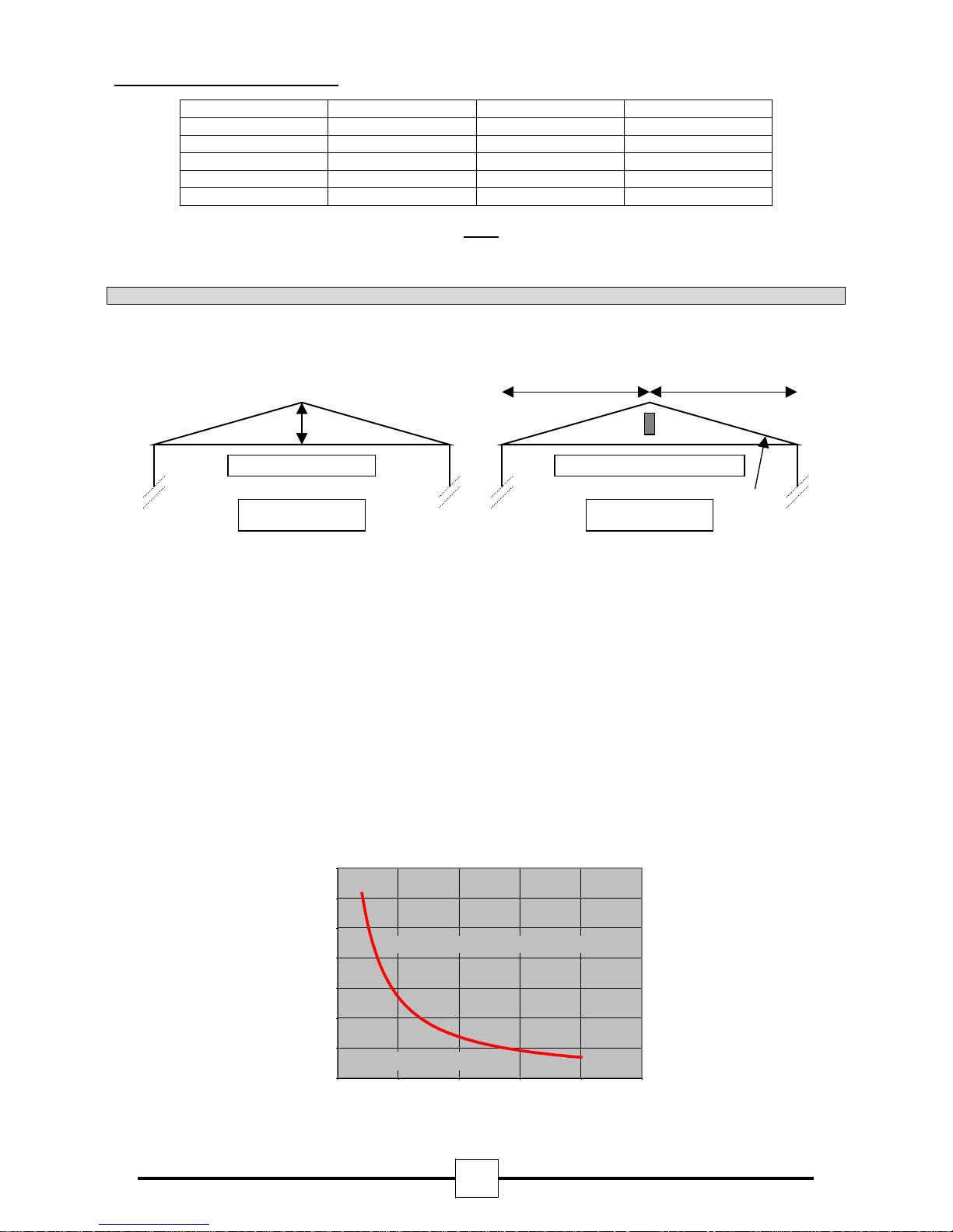
3.1. Detector Positioning In Apex Of Sloping Ceiling.
A ceiling is defined as sloping if the distance from the top of the apex to the intersection of the ceiling and
adjacent wall is greater than 0.6 metres. See Fig. 1.
Υ Υ
Χ
Slope if Χ ≥ 0.6 Metres
=
+
Fig. 1. Fig. 2.
Φ
When a Detector is positioned in the apex of a ceiling (See Fig. 2), the lateral beam distance covered (Υ) can
be increased in relation to the angle of pitch (Φ), up to a maximum of 25%.
For Example:
If the pitch angle is 20 degrees, the lateral coverage can be increased from 7.5 metres either side of the beam
(Υ) to:
Υ = 7.5 + (7.5 x 20/100) metres
Υ = 9 metres
Therefore, with a roof pitch of 20 degrees the lateral coverage can be increased from 7.5 metres either side of
the beam to 9 metres either side of the beam, but only for the beam positioned in the apex. All other
calculations remain the same.
Limit to when a beam detector must be positioned in
Angle of
Pitch
in degrees
22318.37.01 15.09.05
35.0
30.0
25.0
20.0
15.0
10.0
5.0
0.0
0 5 10 15 20 25
Beam detector must be positioned in apex
Roof can be defined as flat
roof apex
Width of Room in metres
3
Page 5

www.acornfiresecurity.com
www.acornfiresecurity.com
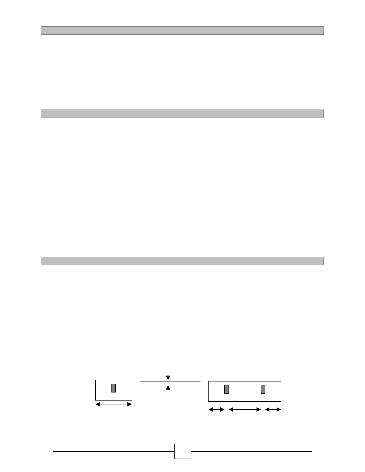
3.2. Detector Positioning In Atrium.
If the detector is to be placed in an atrium, or near glass/polished surfaces, the prism(s) should be offset from the central
line of sight (approximately 300mm), and angled back to the beam detector. This can be either on the vertical or horizontal
axis. This will reduce the amount of spurious returned signal from the glass/polished surfaces. The reflected signal from the
prism(s) will be returned to the detector in the normal way.
Normal Prism(s) position and
central line of sight
Offset Prism(s) position and beam path
Plan View
Detector
head
4. Installation.
Pre-installation at Ground Level.
Confirm that all parts have been supplied as listed in the parts list. See page 11.
Select the required alarm threshold using switches 3 and 4 (See fig. 4. for switch configuration settings). The
factory default setting is 35% this should be adequate for most environments, if the Detector is to be installed
into an exceptionally dirty environment change the threshold to 50%.
The Detector Head Assembly is now ready for installation. If switches 3 and 4 require resetting after installation,
a power down reset is required (entering into Alignment Mode can also be used as a reset).
4.1. Detector Head Assembly Installation.
Remove the outer cover before installation; this is only to prevent the cover becoming dislodged during
handling.
Do not mount on plasterboard or cladded walls as these surfaces do, and will move.
Determine the position of the Head Assembly, which must be mounted on a
0.6 metres below the ceiling, and no closer than 0.5 metres to an adjacent wall or structure. Ensure that there is
a clear l ine of sig ht to the proposed position of the prism, which is to be mounted on a solid structure between
5 and 100 metres directly opposite the Detector (range dependent on model).
Using the template provided mark and install all 4 fixing points to the structure. The rear mounting plate of the
Detector Head Assembly is provided with 4 keyhole slotted apertures to allow for easy installation onto the 4
fixing points.
Replace the outer cover.
Terminate the field wiring. See section 8.
4.2. Prism Installation.
Due to the principle of the detector i.e. reflective, the prism must NOT
polished reflective surface.
Mount the Prism on a solid structure, 90º to the beam path, between 5 to 50 metres (MAB50R), and 50 to100
metres (MAB50R) directly opposite the Detector.
MAB50R = MAB100R =
1 Prism 4 Prisms
solid structure
be mounted on glass or a
between 0.5 and
22318.37.01 15.09.05
4
Page 6

www.acornfiresecurity.com
www.acornfiresecurity.com
Ensure that there is a clear line of sight to the Detector, taking care that no moving objects i.e. doors,
mechanical lifting equipment etc, will interfere with the beam path between the Detector and Prism.
Note: On ranges of ≥5 metres and ≤50 metres use a MAB50R.
On ranges of >50 metres and ≤100 metres use a MAB100R.
5. Prism Targeting Mode.
Apply power to the Detector. There is a 5 seconds pre-charge delay after power is applied to allow the internal
circuits to stabilise correctly.
Do not remove the detector from the wall during this action.
Using the mode switch (See fig. 4) select Prism Targeting Mode (Switch will be in the up position). At this time
there may be a fault condition showing on the panel.
Find the prism by adjusting the horizontal and vertical thumbwheels until the Amber LED is flashing. Both the
Red and Amber LED will be OFF when no signal is being received. The Red LED will start to flash when a weak
signal is received. When a stronger signal is received, the Red LED will extinguish and the Amber LED will start
to flash.
• At this point it is essential to test that the prism and not another surface is
reflecting the beam
This can easily be confirmed by covering the prism with a non-reflecting surface and confirm that the AMBER
and RED indicators are OFF. Please read this in conjunction with section 10.
6. Alignment Mode.
Mechanical alignment is provided by two adjustment thumb wheels on two sides of the Detector, positioned just
behind the Detector Head cover. Adjustment is achievable in both axes.
6.1. Enabling Alignment Mode.
Do not remove the detector from the wall during this action.
Using the mode switch (See fig. 4) select Alignment Mode (Move switch to the middle position). At this time
there be may a Fault condition showing on the panel.
6.2. Adjustment in Alignment Mode.
The Detector will automatically adjust its infrared beam power and receiver sensitivity to give an optimum
receiver signal strength.
The alignment progress is indicated by the colour and state of the indicator lamp on the front of the Detector.
•
FLASHING RED
The Detector is receiving too much signal and is attempting to reduce the infrared power output to
compensate
on the distance between Detector and Prism, the shorter the distance the longer the time.
• FLASHING AMBER
The Detector is receiving a weak signal and is attempting to increase the infrared power output.
• OFF
The Detector has optimised the infrared power and receiver gain for the current orientation of the Detector
and Prism. This does not mean that the Detector to Prism alignment is at its optimum, i.e. if the power
is too high, a misaligned Detector may be receiving a fringe reflection from another object.
• FLICKERING RED/AMBER
This state can occur sometimes. It means that the infrared power is stepping through the optimum setting.
22318.37.01 15.09.05
at this point until the indicator lamp is
. Wait
.
, this may take up to 20 seconds depending
OFF
Continue to flow diagram for procedure.
5
Page 7

A
A
6.3. Alignment Process Flow Diagram.
umbwheel.
www.acornfiresecurity.com
www.acornfiresecurity.com
Reverse the
direction of the
thumbwheel
Repeat the
process for the
other thumbwheel
After selecting alignment mode
wait until both LED’s stop
flashing
Slowly adjust a thumbwheel in
one direction and observe the
mber Red
LED’s
LED
flashing?
No
Both
thumbwheels
adjusted?
Yes
For optimum alignment,
deflection of the beam in
all four planes should
cause the Amber LED to
flash first
Exit Alignment
Mode and enter the
Operating Mode
mber
Stop turning the
thumbwheel and
wait for the Red
LED to stop
flashing.
Slowly turn the
thumbwheel in the
same direction
LED
flashing?
Neither
Stop turning the
th
Red
22318.37.01 15.09.05
6
Page 8

A
www.acornfiresecurity.com
www.acornfiresecurity.com
6.4. Exiting Alignment Mode.
Do not remove the detector from the wall during this action.
Using the mode switch (See fig. 4) select Run Mode (Switch will be in the down position).
On exiting alignment mode the Detector will perform an internal calibration check. If this fails, which would be
due to bad alignment or either electrical or optical noise, the power level will try to compensate. If, after 60
seconds, the power level is still not correct, a Fault will be signalled to the control panel. The alignment
procedure must be repeated.
If the internal calibration check completes satisfactory, the Detector will enter its normal running mode.
7. System Testing.
After successful installation and alignment the System will require testing for both alarm and fault conditions.
7.1. Alarm (smoke) Test.
Taking note of the threshold selected during installation (default 35%).
Select obscuration mark on filter to correspond with the Detector alarm threshold (see fig. 3).
Place the filter over the receiver optics (Top of Detector Head − opposite end to the status indication LED’s) at
the correct obscuration value determined by the threshold selected, i.e. if a threshold of 35% has been selected
position the filter just past the 35% obscuration value on the filter (see fig 3.).
Take care not to cover the transmitter optics.
The Detector will indicate a fire within 10 seconds by illuminating the Red LED and activating the panel.
7.2. Fault Test.
Cover the Prism totally with a non-reflective material and confirm that the Detector signals to the control panel a
fault condition after approximately 10 seconds. When the prism is uncovered, the fault condition will
automatically reset after a period of 10 seconds when the obstruction is removed.
lign filter for correct obscuration/threshold setting
Í obscuration value
Receiver Optics
Fig. 3.
22318.37.01 15.09.05
RED
7
Transmitter Optics
Status Indication LED’s
Page 9

www.acornfiresecurity.com
www.acornfiresecurity.com
8. Connection and Configuration Settings.
8.1. Field Wiring.
The Loop wiring is accessed through the back plate of the Detector Head (See Fig 4). The small 2-pin
connector on the left is not used.
8.2. DIP Switch Settings.
Access to the configuration settings is through the back plate of the Detector Head (See Fig 4). The 4-way DIP
is used to select the beams sensitivity.
8.3. Typical Single Zone Wiring.
Loop Finish
Fire Panel
Connections
Loop Start
MAB50R & MAB100R
Loop IN
Loop +ve Loop -ve
Connections
Loop OUT
Suitable fire rated cable
22318.37.01 15.09.05
8
Junction box,
join screens here
2 core + screen cable
to next device in Loop
From last
device in Loop
Page 10

www.acornfiresecurity.com
www.acornfiresecurity.com
9. Detector Interface Assembly Configuration Settings.
22318.37.01 15.09.05
Fig. 4.
9
Page 11

www.acornfiresecurity.com
www.acornfiresecurity.com
10. Beam clearance.
Most reflective beams produce a focused beam to a reflector on the opposite side of the protected area. The
returned signal is then sampled and any obscuration calculated. If there are highly reflective surfaces, or
objects near the beam path, there may be a possibility that some of the beam energy is inadvertently reflected
into the receiver, rather than via the reflector. This may increase the possibility of faults or false alarms. Hence
the importance of following the recommendations in
It is, for this reason, recommended that the beam path should be surveyed to confirm that a reflective beam can
be used. As a general rule of thumb there should be at least 0.5m diameter clearance down the entire beam
path. If there are highly reflective objects within 1 metre diameter of the beam path for the first 20 metres of the
beam path (for the MAB100R), then tests should be carried our to see if the beam is suitable.
Beam
First 20 metres
1 metre
diameter
clearance
0.5 metre diameter clearance down rest of beam path
Section 5
of this installation guide.
Reflector(s)
11. Technical Data.
• Operating Range MAB50R 5 to 50 metres
• Operating Range MAB100R 50 to 100 metres
• Supply Voltage 18-30Vdc
• Quiescent Current (no LED’s illuminated) <5mA
• Alarm Current <9mA
• Alignment Current <18mA
• Power up Time approx 10 seconds
• Operating Temperature -30°C to 55°C
Tolerance to Beam Misalignment at 35% Detector ± 0.8°, Prism ± 5.0°
•
• Fire Alarm Thresholds 2.50dB (25%), 3.74dB (35%), 6.02dB (50%)
• Optical Wavelength 880nm
• Head Maximum Size Width 130mm, Height 210mm, Depth 120mm
• Weight 740 gm
22318.37.01 15.09.05
10
Page 12

Short circuit Isolators
www.acornfiresecurity.com
www.acornfiresecurity.com
Each of the beam detectors in this range contains an integral short circuit isolator, which operates between the
IN -ve terminal and the OUT -ve terminal. The isolator operates in conjunction with the control panel when a low
parallel resistance fault of typically 200Ω is presented between Loop +ve and Loop -ve.
Short Circuit Isolation Data
(Integral with each detector)
Total loop Resistance for correct operation of
short circuit isolator.
Continuous Current allowable through isolators. 700mA (max)
50Ω max
Isolator Resistance in closed state.
Leakage Current into direct short circuit isolator
open.
Parallel Fault Resistance to be seen at the
Control Panel for isolators to open
0.13Ω (max)
13mA (max)
200Ω (typ)
12. Service / Application Notes.
• For full compliance with BS5839 part 5, use 25% and 35%(default) thresholds. The threshold of 50% is
recommended for hostile and extreme environments.
• Red LED (constant or flashing) will indicate FIRE.
Faults will NOT be signalled via the local amber LED of the beam detector. The fire panel will indicate that
•
the beam detector is in fault and the fault type.
13. Parts List.
1 off: Detector Head Assembly
•
• 1 off: Prism for the MAB50R
• 4 off: Prisms for the MAB100R
• 1 off: Dual Test Filter
• 1 off, 4 way Connector for in line wiring
• 1 off, 4 way Connector for right angle wiring
22318.37.01 15.09.05
11
www.cooper-ls.com
 Loading...