

Page 1

DC58M+
8 Channel Digital Communicator &
Digi-Modem
Installation & Programming
Instructions
Page 2

CONTENTS
Regulatory Requirements
General . . . . . . . . . . . . . . . . . . . . . . . . . . . . 3
Application. . . . . . . . . . . . . . . . . . . . . . . . . . 3
Approval. . . . . . . . . . . . . . . . . . . . . . . . . . . . 3
Connections. . . . . . . . . . . . . . . . . . . . . . . . . 3
Mounting The DC58M+ . . . . . . . . . . . . . . . . 3
Compatibility with PABXs. . . . . . . . . . . . . . . . 3
Connection To Telephone Network . . . . . . . 4
Overview
General . . . . . . . . . . . . . . . . . . . . . . . . . . . . 4
Operating Modes. . . . . . . . . . . . . . . . . . . . . 4
NVM Programming . . . . . . . . . . . . . . . . . . . . 4
Technical Specifications. . . . . . . . . . . . . . . . 4
Operation
General . . . . . . . . . . . . . . . . . . . . . . . . . . . . 5
Three-Way Calling . . . . . . . . . . . . . . . . . . . . 5
Line Fault Monitor . . . . . . . . . . . . . . . . . . . . . 5
Temporary Out of Service. . . . . . . . . . . . . . . 5
Point ID Extended Format . . . . . . . . . . . . . . . 6
Modem . . . . . . . . . . . . . . . . . . . . . . . . . . . . 6
Installation
Plug-on Installation . . . . . . . . . . . . . . . . . . . . 6
Telephone Line Connections . . . . . . . . . . . . 7
NETLCD/TS900 Keypad Connections . . . . . . 7
Testing . . . . . . . . . . . . . . . . . . . . . . . . . . . . . 8
Programming
Programming Menu . . . . . . . . . . . . . . . . . . . 9
Telephone Numbers. . . . . . . . . . . . . . . . . . . 10
Account Numbers . . . . . . . . . . . . . . . . . . . . 10
Reporting Channels . . . . . . . . . . . . . . . . . . . 10
Set/Day Channels. . . . . . . . . . . . . . . . . . . . . 10
Restore Channels . . . . . . . . . . . . . . . . . . . . . 10
Dialling Modes . . . . . . . . . . . . . . . . . . . . . . . 11
Test Call Period . . . . . . . . . . . . . . . . . . . . . . . 11
Point ID Extended Format . . . . . . . . . . . . . . . 11
Temporary Out of Service . . . . . . . . . . . . . . 11
Monitor Mode
Introduction . . . . . . . . . . . . . . . . . . . . . . . . . 12
Transmitted Data Specification . . . . . . . . . . 12
Typical Test Call . . . . . . . . . . . . . . . . . . . . . . 12
Other Monitor Messages. . . . . . . . . . . . . . . . 12
NVM Programming Form . . . . . . . . . . . . . . . 13
2
DC58M+ Installation Instructions
Page 3
Regulatory Requirements
General
The DC58M+ digital communicator/modem
must be installed by an electrically competent
person. Before attempting to install the DC58M+,
the installer must be aware of the following:
Application
The DC58M+ digital communicator/modem is
suitable for connection to the following types of
telephone line:
l
Direct exchange lines (PSTN) supporting DTMF
(Tone dialling).
l
PABX exchanges (with or without secondary
proceed indication).
Approval
The DC58M+ digital communicator/modem is
not suitable for connection as an extension to a
pay phone or 1+1 carrier systems. The DC58M+
digital communicator/modem is approved for the
following usage:
l
Automatic call initialisation
l
Operation in absence of proceed indication
l
Automatic dialling
l
Multiple repeat attempts
l
Serial connection
l
Three-way calling using BT Network Services
l
Modem
Usage other than the approved usage or failure to
comply with the installation and programming
instructions may invalidate any approval given to
the apparatus. The approval Label for the
DC58M:
This product is manufactured to meet all
European Economic Area Telecommunication
networks requirements.
Connections
Connection terminals on the DC58M+ are
described as either "Safety Extra-Low Voltage"
circuits (SELV) or "Telecommunications Network
Voltage" circuits (TNV).
The PCB layouts on page 7 shows the two types of
circuits.
+
It is important that the installer ensures that
TNV connections are only connected to
the PSTN and SELV circuits are only
connected to other circuits designated as
SELV circuits.
+
Interconnection circuits should be such
that the equipment continues to comply
with the requirements of 4.2 of EN 41003
for TNV circuits and 2.3 of EN 60950 for
SELV circuits, after making connections
between circuits.
Mounting The DC58M+
The DC58M+ is supplied inside a polycarbonate
enclosure and is small enough to be mounted
inside most control panels.
+
Once the unit is installed the cover must be
secured using the screws supplied.
Compatibility with PABXs
The DC58M+ is only approved for use with
compatible PABX systems. Correct operation in all
circumstances is not guaranteed. If you
experience any difficulties contact Menvier
Technical Support.
3
DC58M+ Installation Instructions Regulatory Requirements
0186
Page 4
Connection To Telephone Network
The person responsible for connection of the
DC58M+ to a PABX system is as follows:
l
If the wiring is owned by British Telecom
PLC - British Telecom
l
If the wiring is not owned by British Telecom,
either:
(a) British Telecom
(b) The authorised maintainer
(c) A professional installer after 14 days written
notice to the authorised maintainer.
Overview
General
The DC58M+ digital communicator consists of a
single PCB fitted in a small polycarbonate case. It
is used to transfer fast format status information
from an alarm system to a dedicated Alarm
Receiving Centre (ARC) via the Public Switched
Telephone Network (PSTN). The DC58M+ also
functions as a V21/V22bis modem. The DC58M+
is required when using the up/downloading
feature on compatible Menvier control panels.
Operating Modes
The DC58M+ can be used as a plug-on
communicator, in this mode the communicator is
plugged in to the control panel using the
appropriate connections cable.
NVM Programming
All programmed data is stored in a plug-in NVM
(Non-Volatile Memory) which will be retained for
up to five years with no power present. The NVM
can be programmed by using a Menvier LCD
Remote Keypad (P/No. NETLCD/TS900.REM) and
an engineer's interface lead (P/No. NETEKI) which
will plug directly on to the DC58M+. Alternatively
the NVM can be programmed using the desktop
programmer PP5.
Your ARC will normally provide a programming
service and will supply a pre-programmed NVM
on request or alternatively fill in the programming
form at the back of this manual and return/fax it to
Menvier Security (Repairs Dept.).
Technical Specifications
Supply: 11.5V - 14V; <35mA dc (Standby);
135mA dc (Active)
The installer must ensure that power
drawn by the DC58M+ plus any
other auxiliary apparatus is within
the rating of the control panel (host)
power supply.
Low Battery: Detection threshold is at 10.8V +/-
0.2V
Modem: 300/300 Baud (V21), 2400/2400
Baud (V22bis)
Programmer: NETLCD/TS900 remote keypad &
interface lead or PP5.
Case Size: 142(w) x 82(h) x 36(d) mm.
Weight 265g
REN value: 0.0
Series Voltage Drop
The voltage drop introduce by the series
connection through the DC58M+ at a line current
of 40mA is 0.1V. When used with other apparatus
(telephone, fax etc.) the total voltage drop
@40mA MUST NOT exceed 2.0V.
4
Overview DC58M+ Installation Instructions
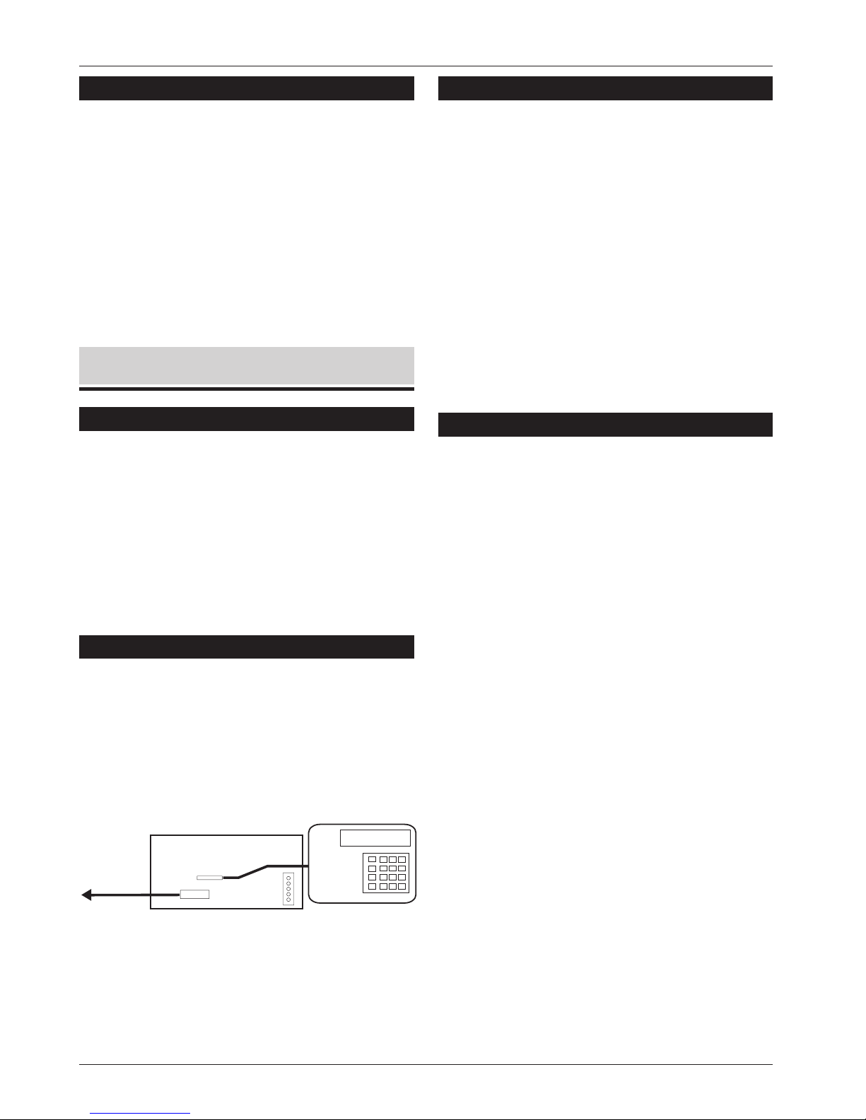
Plug-on Mode
NETLCD/TS900
Remote Keypad
(Programmer)
Plug-on to
Menvier control
panels
Figure 2 Operating Modes
Page 5

Operation
General
When triggered, the DC58M+ seizes the PSTN line.
When a dial tone is detected the DC58M+ lights
the indicator (LED).
1. The appropriate telephone number is dialled,
when answered, the alarm receiver will send a
I.D tone. If no I.D tone is received, the DC58M+
will release the line, and repeat the process a
maximum of three times to each selected
telephone number.
2. When the DC58M+ receives the ID tone it
transmits the appropriate data in the selected
format. If the data is successfully received the
alarm receiver responds with an
acknowledgement tone. The DC58M+
releases the line and flashes the red LED 4
times.
3. If the acknowledgement tone is not received,
the DC58M+ releases theline and tries again.
4. After the third dialling attempt has failed a line
fault is signalled to the control panel to allow
any programmed bell delayto be cancelled.
Three-Way Calling
This is one the new features that is available from BT
Network Services, for this feature to work correctly
the telephone line must have this service enabled
(contact BT for further details). In non-UK countries
you can enabled or disable this feature (as well as
pulse dialling) in programming. See page 9,
Porgramming.
When the DC58M+ is triggered the unit checks for
incoming ringing or off hook (someone trying to
block the call). The unit then sends a "Recall"
signal, which is detected by the exchange as a
request for a new line. With a new line available the
DC58M+ then attempts toconnect with the ARC.
If the DC58M+ is connected to an older pulse dial
only exchange, the numbers being dialled must
be selected to "Pulse" dial, see "Telephone
Numbers" on page 10. This will disable the
three-way calling facility as it is not available on the
older type exchanges.
Line Fault Monitor
The line fault monitor continuously monitors the
PSTN line and will detect:
l
The loss of line voltage (cut line)
l
A line voltage less than 35V (parallel
telephone off hook)
l
An incoming ringing signal that will try and
prevent DC58M+ operation
If the DC58M+ is used on a shared line then the
line fault monitor can be selected to only monitor
a cut line by setting the "HI/LO SECURITY" option to
"LO". It is also recommended that "Three-Way
Calling" is used (see above) so that the security of
the system is not compromised.
Temporary Out of Service
In addition to the line fault monitor, the DC58M+
can be programmed to perform a more detailed
line test at pre-set intervals. The DC58M+ will seize
the line and dial all digits but the last one of
telephone number 1. If the unobtainable tone is
NOT detected it is assumed that the line is healthy
and the unit releases the line. If the unobtainable
tone is detected, a line fault is signalled.
Note: This feature must be disabled if this product
is used in Germany.
5
DC58M+ Installation Instructions Operation
Page 6

Point ID Extended Format
This is a new format which is used to send
additional fast format data to the alarm receiver.
The additional information can be used to
indicate the circuit that caused the alarm, the user
that set/unset the system etc. For the DC58M+ to
send this additional data, the unit must be
plugged on to a Menvier control panel that
supports "Point ID Extended Format"' and report to
a compatible alarm receiver.
Modem
When a call is made to the alarm site the DC58M+
will pick up the call and attempt to connect to the
modem that is connected to the P.C. If successful
the communication link is established and data
can be transferred. When the Modem is on-line
the red LED on the DC58M+ flashes continuously
until the communication link is broken. If during the
Modem operation the control panel generates an
alarm which is required to be transmitted to the
ARC, the DC58M+ will suspend the Modem
operation and attempt to communicate with the
alarm receiver.
Installation
A LED 1
Activity LED. On whilst communicator is active.
Flashes on and off 4 times when successfully
communicated with the ARC. Flashes
continuously when modem is in operation.
B Test Call
Short these two pins to initiate a test call.
C NVM
Removable Non-Volatile Memory used to store
all programmed data.
D JP2 (SELV)
Connector for Menvier control panels.
E JP1 (SELV)
Connector to NETLCD/TS900 remote keypad
(Programmer).
F Telephone Connections (TNV)
Terminal connections to the telephone line.
G HI/LO SECURITY
Line fault monitoring level:
Link fitted = High Security
Link removed = Low Security
Plug-on Installation
1. Isolate ALL power from the control panel
(battery and mains).
2. Do not attempt to continue if the mains or
battery supply is still present.
3. Remove the cover from the DC58M+ case
and if appropriate fita pre-programmed NVM.
4. Connect the interface lead to the control
panel connector (DIGI MODEM) via the cable
entry hole in the base, then connect the lead
onto JP2 on the DC58M+ (marked TO
CONTROL PANEL).
6
Installation DC58M+ Installation Instructions
A
A1
B
B1
NVM
TEST
CALL
TS900
REMOTE
A
E
B
C
D
F
G
HI/LO SECURITY
TO
CONTROL
PANEL
JP 2
JP 2
Figure 3 DC58M+ PCB Layout
Page 7

5. Set the "HI/LO SECURITY" link to the appropriate
setting.
6. Secure the DC58M+ base to the control panel
base using the self-adhesive pads.
7. Refer to "Telephone Line Connections".
Telephone Line Connections
1. Connection to the telephone network must be
made via an NTE5 master socket (Line Box).
2. Using the cable type 1/0.5mm CW1308, strip
back 5mm of the required cores and feed
through the DC58M+ cable entry, see
Figure 4.
+
Keep all telephone cables at least 5mm
away from other alarm cables.
3. CW1308 cable is available from RS
Components (Part No. 368-413). Alarm or any
other type of cable must not be used.
4. Connect the three cores to the terminal blocks
marked A and B.
5. Remove the two screws from the BT master
jack socket and remove the bottom section
from the master jack.
6. Connect the cable from A and B terminals on
the DC58M+ to the BT master jack terminals,
see Figure 4.
7. A special insertion tool will be required to
connect the cable to the master jack, this is
available from RS Components (Part No.
470-487).
8. Replace the bottom section of the master jack
socket and do up the two screws. Refer to
"Testing" (see below).
NETLCD/TS900 Keypad Connections
To convert a standard NETLCD/TS900 remote
keypad into a DC58M+ programmer the
following is required:
NETLCD
TS900REM
32 character LCD remote keypad.
NETEKI Networker Engineer's Keypad
Interface lead.
7
DC58M+ Installation Instructions Installation
To PSTN
A1
B1
B
A
Phone
Red
White
Green
Blue
5
RJ11 Connector
Terminals at Jack
Adaptor Lead 485226
Direct Connection DC58M+
Using Adaptor Lead DC58M+
2
3
4
A1
B1
B
A
Figure 4 Telephone Line Connections
Figure 5 Engineer's Keypad Connections
Page 8

Testing
Once all the installation steps have completed,
proceed as follows:
1. Ensure that you have informed the ARC that
you will be sending test calls.
2. Connect power to the control panel.
(a) If the NVM is un-programmed or fitted
incorrectly the red LED will flash rapidly.
(b) If the DC58M+ is to be programmed using
the NETLCD/TS900 remote keypad, plug it
onto the connector labelled "TS900
REMOTE". Refer to "Programming" for
further details.
3. Send a test call by momentarily shorting the
"TEST CALL" pins together, see Figures & 3. This
will initiate a test transmission to the ARC.
+
The DC58M+ will not send a test call if
there is a parallel hand-set off hook.
4. Trigger all the relevant channels by:
(a) Setting and unsetting the control panel to
send open/close signals.
(b) Set the system and cause a full alarm to
send an intruder signal.
(c) Press any PA buttons to send a PA signal.
(d) Activate any other devices that require
testing.
5. Unplug the NETLCD/TS900 remote keypad and
secure the cover of the DC58M+ using the two
screws supplied.
6. Finally replace and secure the cover on the
control panel.
8
Installation DC58M+ Installation Instructions
Page 9

Programming
Programming Menu
9
DC58M+ Installation Instructions Programming
TELEPHONE NO.1
018112345678
TELEPHONE NO.2
018112345687
REPORTS TO NO.1
**34***8
Enter Telephone No. 1
Press any key
= Clear number
= Pulse Dial (P) or Pause (-)
= Tone Dial (T)
DC58M+ Vers 1.0
Press Any Key
Enter Telephone No. 2
TELEPHONE NO.3
018112345679
ACCOUNT NO.1
0001
Enter Telephone No.3
Enter account No.1
ACCOUNT NO.2
0001
ACCOUNT NO.3
0001
Enter account No. 2
Enter account No. 3
Select channels that report
to tel No.1 by pressing [1] - [8]
REPORTS TO NO.2
*234***8
REPORTS TO NO.3
*234***8
Select channels that report
to tel No.2 by pressing [1] - [8]
Select channels that report
to tel No.3 by pressing [1] - [8]
SET/DAY CHANNELS
***4****
Select Set/Day (Open/Close)
channels by pressing [1] - [8]
RESTORE CHANNELS
**34****
Select Restore channels
by pressing [1] - [8]
= Consecutive
= Alternative
= All
Dialling Mode
is Consecutive
Select dialling mode:
= Disabled
= Daily
= Weekly
TEST CALL PERIOD
Disabled
Select test call period:
= Fortnightly
Digi Format
Standard
Select output type:
= Standard
= Extended Limited
= Extended Full
= Disabled
= Daily
= Weekly
T.O.S Calls are
Disabled
Select Temporary Out of
Service monitoring period:
= Fortnightly
3-WAY CALLING
Enabled
Enable/Disable 3-way calling:
= Disable
= Enabled
Finish
Page 10

Telephone Numbers
Up to three telephone numbers can be
programmed, each number can be up to 16
digits long. As part of the number, special codes
can be inserted to allow for pulse dialling (P), tone
dialling (T) and a 4 second pause (-) for PABX
systems.
When the DC58M+ dials a telephone number it
will automatically select the correct dialling
format. However, the format can be forced if
required.
Selecting Tone Dialling
Tone dialling is the modern format and is
sometimes referred to as Multiple Frequency (MF)
or Dual Tone Multiple Frequency (DTMF). To force
the number to be dialled in this format press [C]
before entering the telephone number. The
telephone number will be prefixed with a "T" to
indicate tone dialling.
Inserting a Pause for PABX's
If the DC58M+ is connected to an internal PABX
telephone exchange system, normally the
exchange requires a pre-fixed digit to be dialled
before obtaining an outside line (normally 9).
Some exchanges also require a pause after the
pre-fixed digit before dialling the telephone
number. To insert a 4 second pause, enter the
PABX digit (normally 9) then press the [B] key the
display will show "9-". Now enter the telephone
number.
+
When programming telephone numbers it
is very important check that they have
been entered correctly otherwise the
DC58M+ could dial a private number
inadvertently.
Account Numbers
This is a 4 digit number that the alarm receiving
centre uses to identify the alarm site. Up to three
account numbers can be programmed. Account
numbers can only be programmed if the
corresponding telephone number is
programmed i.e., if "Telephone No.2" is blank then
the option to program "Account No.2" is not
available.
Reporting Channels
Each channel can be programmed to report to
any combination of telephone numbers. For
example channel 1 can be programmed to
report to all telephone numbers, whereas channel
3 can be programmed toonly report to telephone
number 1. Reporting channels can only be
programmed if the corresponding telephone
number is programmed i.e., if "Telephone No. 2" is
blank then the option to program "REPORTS TO NO.
2" is not available.
Set/Day Channels
Any channel can be programmed as a '"Set/Day"
channel, this type of channel will report a "Close"
signal when the input channel is active and an
"Open" signal when the input channel is restored.
Normally channel 4 is used to report an
"Open/Close" signal, but if required this can be
changed.
Restore Channels
Any channel can be programmed as a "Restore"
channel, this type of channel will report a "Alarm"
signal when the input channel is active and a
"Restore" signal when the input channel is restored.
If a channel is programmed without "Restore", only
the "Alarm" signal will be transmitted.
+
If any channel is programmed as
"Set/Day", its channel will automatically be
programmed as "Restore".
10
Programming DC58M+ Installation Instructions
Page 11

Dialling Modes
The DC58M+ can be programmed for the
following Dialling Modes:
Consecutive
In this mode the DC58M+ will dial the first
telephone number and attempt to report the
alarm signal. If the attempt fails, it will shut down
and re-dial the first telephone number. If the
second attempt fails, it will shut down for 1 minute
then re-dial the first telephone number again. If
the third attempt fails the the unit shuts down and
now attempts the second telephone number. This
sequence continues until all three attempts to
each telephone number have been used, after
which the unit will shut down completely.
Alternative
In this mode the DC58M+ will dial the first
telephone number and attempt to report the
alarm signal. If the attempt fails, it will shut down
and dial the second telephone number. If the
second attempt fails, it will shut down and dial the
third number. This sequence continues until all
three attempts to each telephone number have
been used, after which the unit will shut down
completely.
All
In this mode the DC58M+ will dial consecutively,
but also requires a successful communication
from all alarm receivers.
Test Call Period
The DC58M+ can be programmed to periodically
send a "Test" signal (Code 9) to the Alarm
Receiving Centre.
Point ID Extended Format
It is possible to send additional alarm information
to the ARC, this can include circuit and user ID. For
full details on the extended information refer to the
relevant control panel "Installation Manual".
+
This feature is only supported by relevant
Menvier control panels, for details on
which control panels support this feature
contact Menvier Technical Support.
Point ID can be setto one of the following reporting
options:
1 Will NOT Report
This disables "Point ID Extended Format" and
the DC58M+ will only report "Fast Format" data
to the alarm receiver.
2 Limited Report
When "Limited Report" is selected the
DC58M+ will only report the extended format
data relating to the channel that is triggered.
For example, if the DC58M+ is programmed
to report channels 2 and 3 (PA and Intruder)
then the unit will only report events relating to
PA and Intruder activations.
3 Full Report
When "Full Report" is selected the DC58M+ will
report all extended format data to the alarm
receiver irrespective of the channels that are
programmed to report. That is, if all eight
channels are programmed as non reporting,
the unit will still report all events to the ARC.
Temporary Out of Service
This feature is used to test the integrity of the
telephone line by dialling all but the last digit of the
first telephone number. If the unobtainable tone is
NOT detected it is assumed that the line is in good
working order, however, if an unobtainable tone is
detected the DC58M+ will signal a line fault
condition.
+
This feature is only supported by relevant
Menvier control panels, for details on
which control panels support this feature
contact Menvier Technical Support.
11
DC58M+ Installation Instructions Programming
Page 12

Monitor Mode
Introduction
When the NETLCD/TS900 remote keypad is left
plugged on to the DC58M+ it will act as a monitor,
so that during testing to the ARC the display will
show the communicator's status.
Transmitted Data Specification
The data transmitted to the alarm receiver is
industry standard fast format. The data contains
the following information:
Account No This is a 4 digit number and is unique
to the installation site.
Channel 1-8 Each channel can report its own
status code:
Code 1 = New Alarm
Code 2 = System Opened
Code 3 = Channel Restored
Code 4 = System Closed
Code 5 = Healthy Channel
Code 6 = Previouslyreported event
Channel 9 This channel is normally referred to
as the status channel and is used to
report the following:
Code 7 = Normal
Code 8 = Low Battery
Code 9 = Test
Typical Test Call
When the "TEST CALL" pins are momentarily shorted
the DC58M+ will send a test call to all
programmed telephone numbers. The display
should show:
Other Monitor Messages
The following monitor messages may also be
displayed:
12
Monitor Mode DC58M+ Installation Instructions
DC58M+ MONITOR
Waiting for I.D
DC58M+ MONITOR
Sending Data
Dialling the first telephone No.
Waiting for the alarm receiver to
answer the call and send its
identenifation tone (I.D).
The alarm reciever is on line
and the DC58 is sending its data.
The data send is displayed.
This is repeated for all
programmed telephone
numbers
The data was accepted and the
alarm reciever has sent its
acknowledgemnt tone.
DC58M+ MONITOR
Dialling Number 1
DC58M+ MONITOR
0001 5555 5555 9
DC58M+ MONITOR
Call Successful
DC58M+ MONITOR
Unobtainable
Dc58 MONITOR
No Ack. Tone
M+
DC58M+ MONITOR
Engaged
Dc58 MONITOR
T.O.S Call Ok
M+
No dial tone detected when the
DC58 went on line.
The number was dialled but an
unobtainable tone was detected.
The alarm receiver is engaged.
No reply from the alarm receiver.
The "Temporary Out of Service" test
call was successful.
The DC58 sent its data to the
alarm receiver, but the receiver
failed to give an acknowledgement
tone (corrupted data).
DC58M+ MONITOR
No Dial Tone
DC58M+ MONITOR
No Answer
Page 13

NVM Programming Form
13
DC58/58M Installation Instructions Monitor Mode
Telephone No. 1
Telephone No. 2
Telephone No. 3
Account No. 1
Account No. 2
Account No. 3
Channel No. 12345678
Reports to No. 1
Reports to No. 2
Report to No. 3
Set/Day Channels
Restore Channels
Three-way Calling
Disabled:
o
Enabled:
o
Dialling Mode Consecutive:
o
Alternative:
o
All:
o
Test Call Period Disabled:
o
Daily:
o
Weekly:
o
Fortnightly:
o
Format
Standard:
o
Extended Format
Limited Report:
o
Extended Format Full
Report:
o
SIA I
o
SIA II
o
T.O.S Monitoring Disabled:
o
Daily:
o
Weekly:
o
Fortnightly:
o
Page 14

14
Monitor Mode DC58/58M Installation Instructions
This page is intentionally blank.
Page 15

15
DC58/58M Installation Instructions Monitor Mode
This page is intentionally blank.
Page 16

496465 Issue 1
16
Monitor Mode DC58M+ Installation Instructions
Cooper Security Ltd.
Security House, Xerox Business Park,
Mitcheldean, Gloucestershire,
GL17 0SZ. England
Product Support Tel: (01594) 545556
Between 09:00 and 17:00, Monday to Friday.
Product Support Fax: (01594) 545501.
Email: menvier.security@dial.pipex.com
www.coopersecurity.co.uk
 Loading...