

Page 1

DC58 & DC58M
8 Channel Digital Communicator &
Digi-Modem
Installation & Programming
Instructions
Page 2

CONTENTS
Regulatory Requirements
General . . . . . . . . . . . . . . . . . . . . . . . . . . . . 3
Application. . . . . . . . . . . . . . . . . . . . . . . . . . 3
Approval. . . . . . . . . . . . . . . . . . . . . . . . . . . . 3
Connections. . . . . . . . . . . . . . . . . . . . . . . . . 3
Mounting The DC58/58M . . . . . . . . . . . . . . . 3
Compatibility with PABXs. . . . . . . . . . . . . . . . 3
Connection To Telephone Network . . . . . . . 4
Overview
General . . . . . . . . . . . . . . . . . . . . . . . . . . . . 4
Operating Modes. . . . . . . . . . . . . . . . . . . . . 4
NVM Programming. . . . . . . . . . . . . . . . . . . . 5
Technical Specifications. . . . . . . . . . . . . . . . 5
Operation
General . . . . . . . . . . . . . . . . . . . . . . . . . . . . 5
Special Information Tones (SIT) . . . . . . . . . . . 5
Three-Way Calling . . . . . . . . . . . . . . . . . . . . 6
Line Fault Monitor . . . . . . . . . . . . . . . . . . . . . 6
Temporary Out of Service. . . . . . . . . . . . . . . 6
Point ID Extended Format. . . . . . . . . . . . . . . 6
Modem (DC58M Only). . . . . . . . . . . . . . . . . 6
Installation
Plug-on Installation . . . . . . . . . . . . . . . . . . . . 8
Stand-alone Installation (DC58 Only) . . . . . . 8
Telephone Line Connections . . . . . . . . . . . . 8
TS900 Remote Keypad Connections . . . . . . 9
Testing . . . . . . . . . . . . . . . . . . . . . . . . . . . . . 9
Programming
Programming Menu. . . . . . . . . . . . . . . . . . . 10
Telephone Numbers. . . . . . . . . . . . . . . . . . . 11
Account Numbers . . . . . . . . . . . . . . . . . . . . 11
Reporting Channels . . . . . . . . . . . . . . . . . . . 11
Set/Day Channels. . . . . . . . . . . . . . . . . . . . . 11
Restore Channels. . . . . . . . . . . . . . . . . . . . . 11
Invert Channels . . . . . . . . . . . . . . . . . . . . . . 12
Dialling Modes . . . . . . . . . . . . . . . . . . . . . . . 12
Test Call Period. . . . . . . . . . . . . . . . . . . . . . . 12
Digicom Outputs . . . . . . . . . . . . . . . . . . . . . 12
Point ID Extended Format. . . . . . . . . . . . . . . 13
Temporary Out of Service . . . . . . . . . . . . . . 13
Ring Count (DC58M Only) . . . . . . . . . . . . . . 13
Monitor Mode
Introduction . . . . . . . . . . . . . . . . . . . . . . . . . 14
Transmitted Data Specification . . . . . . . . . . 14
Typical Test Call . . . . . . . . . . . . . . . . . . . . . . 14
Other Monitor Messages. . . . . . . . . . . . . . . . 14
NVM Programming Form . . . . . . . . . . . . . . . 15
2
DC58/58M Installation Instructions
Page 3
Regulatory Requirements
General
The DC58/58M digital communicator/modem
must be installed by an electrically competent
person. Before attempting to install the
DC58/58M, the installer must be aware of the
following:
Application
The DC58/58M digital communicator/modem is
suitable for connection to the following types of
telephone line:
l
Direct exchange lines (PSTN) supporting DTMF
(Tone dialling) or Loop Disconnect (Pulse
Dialling).
l
PABX exchanges (with or without secondary
proceed indication).
Approval
The DC58/58M digital communicator/modem is
not suitable for connection as an extension to a
pay phone or 1+1 carrier systems. TheDC58/58M
digitalcommunicator/modemisapprovedforthe
following usage:
l
Automatic call initialisation
l
Operation in absence of proceed indication
l
Automatic dialling
l
Multiple repeat attempts
l
Serial connection
l
Three-way calling using BT Network Services
l
Modem
Usageother than theapprovedusage or failure to
comply with the installation and programming
instructions may invalidate any approval given to
the apparatus. The approval Label for the DC58:
The approval Label for the DC58M:
Connections
Connection terminals on the DC58/58M are
described as either "Safety Extra-Low Voltage"
circuits (SELV) or "Telecommunications Network
Voltage" circuits (TNV).
The PCB layouts on page 7shows the two types of
circuits.
+
Itisimportantthattheinstallerensures that
TNV connections are only connected to
the PSTN and SELV circuits are only
connected to othercircuits designated as
SELV circuits.
+
Interconnection circuits should be such
that the equipment continues to comply
with the requirements of 4.2 of EN 41003
for TNV circuits and 2.3 of EN 60950 for
SELV circuits, after making connections
between circuits.
Mounting The DC58/58M
The DC58/58M issupplied inside a polycarbonate
enclosure and is small enough to be mounted
inside most control panels.
+
Oncetheunitisinstalledthe cover must be
secured using the screws supplied.
Compatibility with PABXs
The DC58/58M is only approved for use with
compatible PABX systems. Correctoperation in all
circumstances is not guaranteed. If you
experience any difficulties contact Menvier
Technical Support.
3
DC58/58M Installation Instructions Regulatory Requirements
MENVIER SECURITY
DC58
POWER REQUIREMENTS 12v DC @100mA MAX
REN=0.0
S/1100/3/R/503310
MENVIER SECURITY
DC58M
POWER REQUIREMENTS 12v DC @100mA MAX
REN=0.0
S/1100/3/R/503311
Page 4
Connection To Telephone Network
The person responsible for connection of the
DC58/58M to a PABX system is as follows:
l
If the wiring is owned by British Telecom PLC -
British Telecom
l
If the wiring is not owned by British Telecom,
either:
(a) British Telecom
(b) The authorised maintainer
(c) A professional installer after 14 days written
notice to the authorised maintainer.
Overview
General
TheDC58/58M digital communicator consistsofa
single PCB fitted in a small polycarbonate case. It
is used to transfer fast format status information
from an alarm system to a dedicated Alarm
Receiving Centre (ARC) via the Public Switched
Telephone Network (PSTN). The DC58M offers the
same features asthe DC58 butit also functions as
aV21 modem. TheDC58Mis required when using
the up/downloading feature on compatible
Menvier control panels.
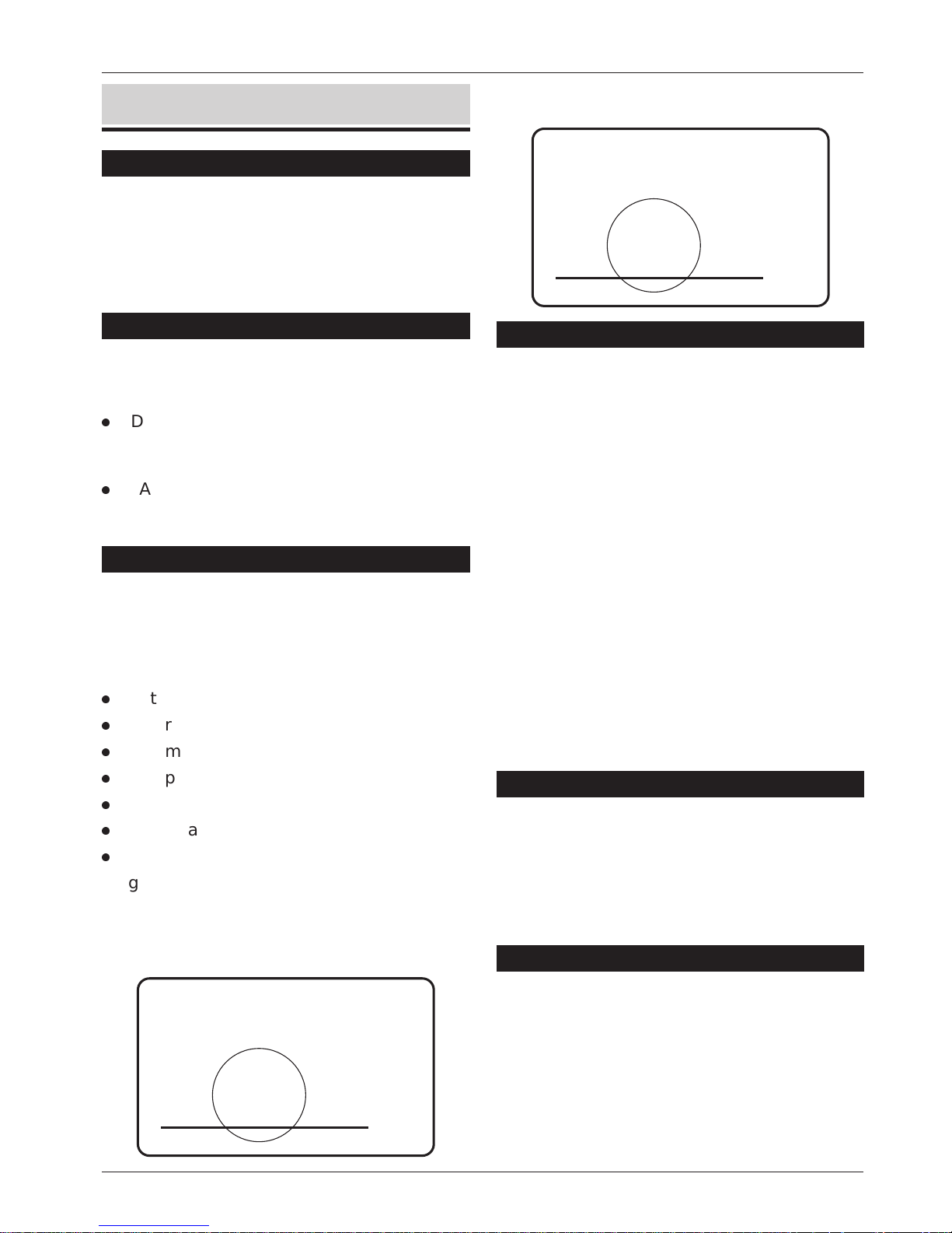
Operating Modes
The DC58 can be used as a stand-alone
communicator,in this mode the communicatoris
hard-wired to the control panel using the
appropriate terminal block connections.
Alternatively the unit can be plugged on to a
suitable Menvier controlpanel, suchas the TS510,
TS700,TS790, TS900, TS2500 orTS2200.Whenused
in this mode the communicator plugs on to the
controlpanel using the lead supplied.TheDC58M
can only be used in the plug-on mode.
4
Overview DC58/58M Installation Instructions
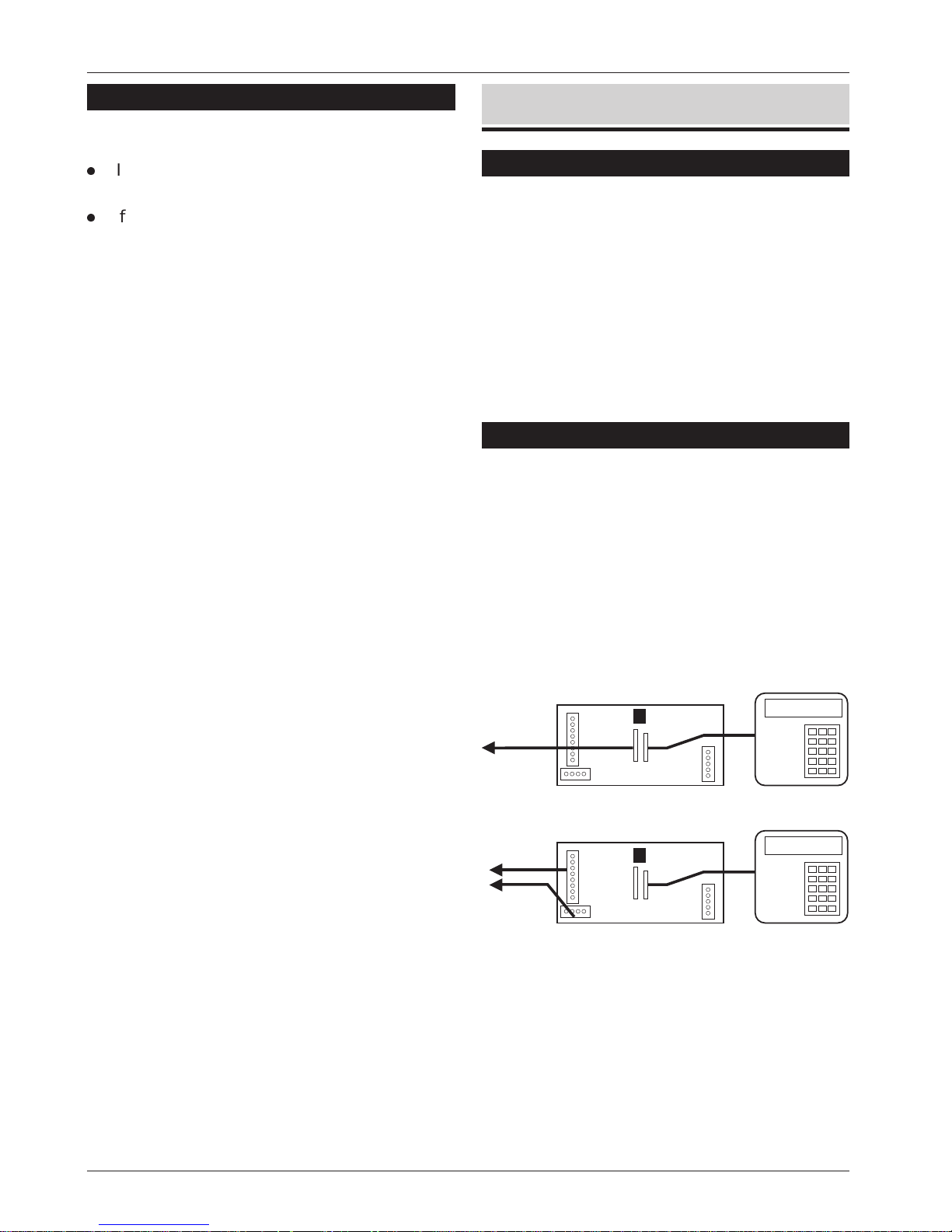
Plug-on Mode
Stand-alone Mode
(DC58 Only)
Terminal
connections for
other control
panels
TS900 Remote Keypad
(Programmer)
TS900 Remote Keypad
(Programmer)
Plug-on to
Menvier control
panels
Figure 1 Operating Modes
Page 5

NVM Programming
All programmed data is stored in a plug-in NVM
(Non-VolatileMemory)whichwill be retainedforup
to five years with no power present. The NVM can
be programmed by using a Menvier LCD Remote
Keypad (P/No. TS900.REM) and an engineer's
interfacelead(P/No.NETEKI) which willplugdirectly
ontothe DC58/58M. Alternatively the NVMcanbe
programmedusingthedesktop programmerPP5.
Your ARC will normally provide a programming
service and will supply a pre-programmed NVM
on request or alternatively fill in the programming
form at theback of thismanual and return/fax it to
Menvier Security (Repairs Dept.).
Technical Specifications
Supply: 11.5V - 14V; 35mA dc (Standby);
100mA dc (Active)
Theinstallermustensurethatpower
drawn by the DC58/58M plus any
other auxiliary apparatus is within
theratingofthecontrolpanel(host)
power supply.
Low Battery: Detection threshold is at 10.8V +/-
0.2V
Outputs: [1+]: Switched +ve @100mA
[2-]: Switched -ve @100mA
Ch 1 - 8: Maximum input voltage 28V.
Channel input trigger either +ve or
-ve applied (JP3)
Modem: 300/300 Baud (V21)
Programmer: TS900 remote keypad & interface
lead or PP5.
Case Size: 142(w) x 82(h) x 36(d) mm.
Weight 265g
REN value: 0.0
BT Approval: DC58 - S/1100/3/R/503310
DC58M - S/1100/3/R/503311
Series Voltage Drop
The voltage drop introduce by the series
connection through the DC58/58M at a line
current of 40mA is 0.1V. When used with other
apparatus (telephone, fax etc.) the total voltage
drop @40mA MUST NOT exceed 2.0V.
Operation
General
When triggered, the DC58/58M seizes the PSTN
line.Whenadialtone is detected,itteststhelineto
determine if Loop Disconnect(Pulse) or Dual Tone
Multiple Frequency (Tone) dialling is required. (If
the dial tone is not detected within six seconds
then Pulse dialling is automatically selected). The
indicator (LED) is then illuminated. If the unit Pulse
dialstheLEDwill flashasthenumbersare dialled.
1. The appropriate telephone number is dialled,
when answered, thealarm receiver will send a
I.D tone. If no I.D tone is received, the
DC58/58M will releasethe line, andrepeat the
process a maximum of three times to each
selected telephone number.
2. If a Special Information Tone (SIT) is detected,
the DC58/58M immediately aborts the call
and tries again.
3. When the DC58/58M receives the ID tone it
transmits the appropriate datain fast format.If
the data is successfully received the alarm
receiver responds with an acknowledgement
tone. The DC58/58M releases the line and
flashes the red LED 4 times.
4. If the acknowledgement tone is not received,
the DC58/58M releases the line and tries
again.
5. After the third dialling attempt has failed a line
fault is signalled to the control panel to allow
anyprogrammedbelldelay tobecancelled.
Special Information Tones (SIT)
These tones are sometimes encountered when
the number dialled is not available or thenumber
is incorrect. If the DC58/58M detects a SIT it will
immediately abandon the call and try again.
5
DC58/58M Installation Instructions Operation
Page 6

Three-Way Calling
Thisisonethenewfeaturesthat is available from BT
Network Services, for this feature to work correctly
the telephone linemust have thisservice enabled
(contact BT for further details).
When the DC58/58M is triggered the unit checks
forincomingringing or off hook (someone tryingto
block the call). The unit then sends a "Recall"
signal, which is detected by the exchange as a
requestforanewline. With anewlineavailablethe
DC58/58M then attempts to connect with the
ARC.
If the DC58/58M is connected to an older pulse
dial only exchange, the numbers being dialled
must be selected to "Pulse" dial, see "Telephone
Numbers" on page 11. This will disable the
three-waycallingfacilityas itisnotavailableonthe
older type exchanges.
Line Fault Monitor
The line fault monitor continuously monitors the
PSTN line and will detect:
l
The loss of line voltage (cut line)
l
Alinevoltageless than 35V(paralleltelephone
off hook)
l
An incoming ringing signal that will try and
prevent DC58/58M operation
If the DC58/58M is used on a shared line then the
line fault monitor can be selected to only monitor
a cut line by setting the "HI/LO SECURITY" option to
"LO". It is also recommended that "Three-Way
Calling" is used (see above) so that the security of
the system is not compromised.
Temporary Out of Service
In addition tothe line fault monitor, theDC58/58M
can be programmed to perform a moredetailed
line test at pre-set intervals. The DC58/58M will
seize the line and dial all digits but the last one of
telephone number 1. If the unobtainable tone is
NOT detected it is assumed that the line is healthy
and the unit releases the line. If the unobtainable
tone is detected, a line fault is signalled.
Point ID Extended Format
This is a new format which is used to send
additional fast format data to the alarm receiver.
The additional information can be used to
indicatethecircuitthat caused thealarm,theuser
thatset/unsetthesystemetc.FortheDC58/58Mto
send this additional data, the unit must be
plugged on to a Menvier control panel that
supports "Point ID Extended Format"' and report to
a compatible alarm receiver.
Modem (DC58M Only)
When a call is made to the alarm site the DC58M
will pick up thecall and attemptto connect to the
modemthat is connected totheP.C. If successful
the communication link is established and data
can be transferred. When the Modem is on-line
the red LED on the DC58M flashes continuously
untilthecommunicationlinkisbroken.Ifduringthe
Modemoperationthecontrolpanelgenerates an
alarm which is required to be transmitted to the
ARC, the DC58M will suspend the Modem
operation and attempt to communicate with the
alarm receiver.
6
Operation DC58/58M Installation Instructions
Page 7

Installation
1 Output 2- (SELV)
Programmable switched -ve output rated
@100mA.
2 Output 1+ (SELV)
Programmable switched +ve output rated
@100mA.
3 Power Input (SELV)
12V power input, only use in stand-alone
mode.
4 CH1 - CH8 (SELV)
Input channels 1 - 8, only use in stand-alone
mode.
5 JP5
Input channel trigger polarity, stand-alone
mode only.
[+] = +ve applied (0v going to 12v)
[-] = -ve applied (12v going to 0v)
6 LED 1
Activity LED. On whilst communicator is active.
Flashes on and off 4 times when successfully
communicated with the ARC. Flashes
continuously when modem is in operation.
7 Test Call
Short these two pins to initiate a test call.
8 NVM
RemovableNon-VolatileMemoryused tostore
all programmed data.
7
DC58/58M Installation Instructions Installation
CH1CH2CH3CH4CH5CH6CH7CH8
12V 0V
1+ O/P 2-
A
A1
B
B1
BC
NVM
TEST
JP5
Trig
Polarity
TS900
REMOTE
TO CONTROL
PANEL
JP2
JP1
HI/LO
SECURITY
12
1
2
3
4 5
6
10
7
8
9
11
Figure 2 DC58 PCB Layout
+
2-
1+
-
A
A1
B
B1
BC
NVM
TEST
TS900
REMOTE
TO CONTROL
PANEL
JP2
JP1
HI/LO
SECURITY
12
1
2
6
10
7
8
9
11
Figure 3 DC58M PCB Layout
Page 8

9 JP2 (SELV)
Connector for Menvier control panels.
10 JP1 (SELV)
Connector to TS900 remote keypad
(Programmer).
11 Telephone Connections (TNV)
Terminal connections to the telephone line.
12 HI/LO SECURITY
Line fault monitoring level:
Link fitted = High Security
Link removed = Low Security
Plug-on Installation
1. Isolate ALL power from the control panel
(battery and mains).
2. Do not attempt to continue if the mains or
battery supply is still present.
3. Remove the cover from the DC58/58M case
andifappropriatefit apre-programmedNVM.
4. Connect the interface lead to the control
panel connector (DIGI MODEM) via the cable
entry hole in the base, then connect the lead
onto JP2 on the DC58/58M (marked TO
CONTROL PANEL).
5. Set the "HI/LO SECURITY" link to the appropriate
setting.
6. Secure the DC58/58M base to the control
panel base using the self-adhesive pads.
7. Refer to "Telephone Line Connections".
Stand-alone Installation (DC58 Only)
1. Isolate ALL power from the control panel
(battery and mains).
2. Do not attempt to continue if the mains or
battery supply is still present.
3. Remove the cover from the DC58 case and if
appropriate fit a pre-programmed NVM.
4. Connect theinputchannelstotheappropriate
outputsonthecontrolpanelfeeding all cables
through the cable entry hole in the base.
5. Ensure that "JP5" is set for the appropriate
polarity.
6. Connect 12V and 0V to the control panel
digicom supply, if aline fault outputis required
use output 1 or 2 and program the output as
line fault.
7. Set the "HI/LO SECURITY" link to the appropriate
setting.
8. Secure the DC58 base to the control panel
base using the self-adhesive pads.
9. Refer to "Telephone Line Connections".
Telephone Line Connections
1. Connection tothe telephone network mustbe
made via an NTE5 master socket (Line Box).
2. Using the cable type 1/0.5mm CW1308, strip
back 5mm of the required cores and feed
through the DC58/58M cable entry, see
Figure 4.
+
Keep all telephone cables at least 5mm
away from other alarm cables.
8
Installation DC58/58M Installation Instructions
A
A1B1
B
BC
Cable Entry
Telephone cable
Type 1/0.5mm CW1308
Telephone line to
"series connected"
telephone, Fax etc.
A = 5 - White/Blue ring
B = 2 - Blue/White ring
BC= 3 - Orange/White ring
3
2
1
6
5
4
Figure 4 Telephone Line Connections
Page 9

3. CW1308 cable is available from RS
Components (Part No. 368-413). Alarm or any
other type of cable must not be used.
4. Connect thethreecores to the terminalblocks
marked A, B and BC.
5. Remove the two screws from the BT master
jack socket and remove the bottom section
from the master jack.
6. Connect thecable from A,B and BC terminals
on the DC58/58M to the BT master jack
terminals, see Figure 4.
7. A special insertion tool will be required to
connect the cable to the master jack, this is
available from RS Components (Part No.
470-487).
8. Replace the bottom section of the master jack
socket and do up the two screws. Refer to
"Testing" (see below).
TS900 Remote Keypad Connections
ToconvertastandardTS900remote keypad into a
DC58/58M programmer the following is required:
TS900REM 32 character LCD remote keypad.
NETEKI Networker Engineer's Keypad
Interface lead.
Testing
Once all the installation steps have completed,
proceed as follows:
1. Ensure that you have informed the ARC that
you will be sending test calls.
2. When used in the stand-alone mode, ensure
that any unused reporting channels are linked
to their healthy condition or re-programmed
notto report, e.g., ifchannel4 is programmed
to report but is not connected to the control
panel, then link it to +12V if the trigger is set to
-ve or to 0V if the trigger is set to +ve.
3. Connect power to the control panel. If the
DC58 is being used as a stand-alone, wait for
approximately 10 seconds for the unit to
automatically configure itself.
(a) If the NVM is un-programmed or fitted
incorrectly the red LED will flash rapidly.
(b) If the DC58/58M is to be programmed
using the TS900 remote keypad, plug it
onto the connector labelled "TS900
REMOTE". Refer to "Programming" for
further details.
(c) If at the end of the 10 seconds any input
channel is active the red LED will
illuminated and the dialling sequence will
commence.
4. Send a test call by momentarily shorting the
"TESTCALL"pinstogether,see Figures 2 & 3. This
will initiate a test transmission to the ARC.
+
The DC58/58M will not send a test call if
there is a parallel hand-set off hook.
5. Trigger all the relevant channels by:
(a) Setting and unsetting the control panel to
send open/close signals.
(b) Set the system and cause a full alarm to
send an intruder signal.
(c) Press any PA buttons to send a PA signal.
(d) Activate any other devices that require
testing.
6. Unplug the TS900 remote keypad and secure
the cover of the DC58/58M using the two
screws supplied.
7. Finally replace and secure the cover on the
control panel.
9
DC58/58M Installation Instructions Installation
Set I/D to "ENG"
NETEKI Lead
Pol.
TS900 Remote Keypad
Blue
White
Yellow
Black
Red
A B
C D E
O/P-
Figure 5 Engineer's Keypad Connections
Page 10

Programming
Programming Menu
10
Programming DC58/58M Installation Instructions
ENT
ENT
Enter Telephone No. 1
Press any key
= Clear number
A
ENT
= Pulse Dial (P) or Pause (-)
B
= Tone Dial (T)
C
Enter Telephone No. 2
ENT
ENT
Enter Telephone No.3
Enter account No.1
ENT
ENT
Enter account No. 2
Enter account No. 3
Select channels that report
to tel No.1 by pressing [1] - [8]
ENT
Select channels that report
to tel No.2 by pressing [1] - [8]
Select channels that report
to tel No.3 by pressing [1] - [8]
ENT
Select Set/Day (Open/Close)
channels by pressing [1] - [8]
ENT ENT
Select Restore channels
by pressing [1] - [8]
ENT
= Consecutive
= Alternative
= All
1
2
3
= Will NOT Report
= Limited Report
= Full Report
1
2
3
Select dialling mode:
Select point ID reporting mode:
ENT
= Disabled
= Daily
= Weekly
1
2
3
= Disabled
= Daily
= Weekly
1
2
3
Select test call period:
Select Temporary Out of
Service monitoring period:
= Fortnightly
4
= Fortnightly
4
ENT
Select Invert channels
by pressing [1] - [8]
ENT
ENT
Select output type:
= Line Fault
= Digi Successful
= Digi Failed
1
2
3
= Digi Active
4
= Serial Coms Fault
5
ENT
Select output type:
= Line Fault
= Digi Successful
= Digi Failed
1
2
3
= Digi Active
4
= Serial Coms Fault
5
ENT
= Instant
= Delayed
1
2
Select Ring Count
(DC58M Only):
Page 11

Telephone Numbers
Up to three telephone numbers can be
programmed, each number can be up to 16
digits long. As part of the number, special codes
can be inserted to allow for pulse dialling (P), tone
dialling (T) and a 4 second pause (-) for PABX
systems.
When the DC58/58M dials a telephone number it
will automatically select the correct dialling
format. However, the format can be forced if
required.
Selecting Pulse Dialling
Pulse dialling is the older (slower) format and is
sometimesreferred to asLoopDisconnect (LD). To
force the number to be dialled in this formatpress
[B] before entering the telephone number. The
telephone number will be prefixed with a "P" to
indicate pulse dialling.
Selecting Tone Dialling
Tone dialling is the modern format and is
sometimes referred to as Multiple Frequency (MF)
or Dual Tone Multiple Frequency (DTMF). To force
the number to be dialled in this format press [C]
before entering the telephone number. The
telephone number will be prefixed with a "T" to
indicate tone dialling.
Inserting a Pause for PABX's
If the DC58/58M is connected to an internal PABX
telephone exchange system, normally the
exchange requires a pre-fixed digit to be dialled
before obtaining an outside line (normally 9).
Some exchanges also require a pause after the
pre-fixed digit before dialling the telephone
number. To insert a 4 second pause, enter the
PABX digit (normally 9) then press the [B] key the
display will show "9-". Now enter the telephone
number.
+
Whenprogramming telephone numbers it
is very important check that they have
been entered correctly otherwise the
DC58/58M could dial a private number
inadvertently.
Account Numbers
This is a 4 digit number that the alarm receiving
centre uses to identify the alarm site. Up to three
accountnumberscanbeprogrammed.Account
numbers can only be programmed if the
corresponding telephone number is
programmedi.e.,if"TelephoneNo.2"isblankthen
the option to program "Account No.2" is not
available.
Reporting Channels
Each channel can be programmed to report to
any combination of telephone numbers. For
example channel 1 can be programmed to
reporttoalltelephonenumbers,whereaschannel
3canbeprogrammed to onlyreporttotelephone
number 1. Reporting channels can only be
programmed if the corresponding telephone
numberis programmed i.e., if"TelephoneNo. 2" is
blankthentheoptiontoprogram"REPORTSTONO.
2" is not available.
Set/Day Channels
Any channel can be programmed as a '"Set/Day"
channel, this type of channel will report a "Close"
signal when the input channel is active and an
"Open" signal when the input channel is restored.
Normally channel 4 is used to report an
"Open/Close" signal, but if required this can be
changed.
Restore Channels
Any channel can be programmed as a "Restore"
channel, this type of channel will report a "Alarm"
signal when the input channel is active and a
"Restore"signalwhentheinputchannel is restored.
Ifachannelisprogrammedwithout"Restore",only
the "Alarm" signal will be transmitted.
+
If any channel is programmed as
"Set/Day", its channel willautomatically be
programmed as "Restore".
11
DC58/58M Installation Instructions Programming
Page 12

Invert Channels
When the DC58/58M is used in the stand-alone
modeitis possible to invert thesignalforanyof the
input channels. An inverted channel will report a
"Restore"signal when the inputchannel is inalarm
and an "Alarm" signal when the input channel is
restored.
Dialling Modes
The DC58/58M can be programmed for the
following Dialling Modes:
Consecutive
In this mode the DC58/58M will dial the first
telephone number and attempt to report the
alarm signal. If the attempt fails, it will shut down
and re-dial the first telephone number. If the
second attempt fails, it will shut down for 1 minute
then re-dial the first telephone number again. If
the third attempt fails the the unit shuts down and
now attempts the secondtelephone number. This
sequence continues until all three attempts to
each telephone number have been used, after
which the unit will shut down completely.
Alternative
In this mode the DC58/58M will dial the first
telephone number and attempt to report the
alarm signal. If the attempt fails, it will shut down
and dial the second telephone number. If the
second attempt fails, it will shutdown anddial the
third number. This sequence continues until all
three attempts to each telephone number have
been used, after which the unit will shut down
completely.
All
In this mode theDC58/58M will dialconsecutively,
but also requires a successful communication
from all alarm receivers.
Test Call Period
The DC58/58M can be programmed to
periodically send a "Test" signal (Code 9) to the
Alarm Receiving Centre.
Digicom Outputs
The DC58/58M has two programmable outputs,
[1+] is a switched +ve output and [2-] is a
switched -ve output. Both outputs are rated at
100mA and can be programmed to one of the
following types:
1 Line Fault
Activates the output when the unit detects a
telephoneLinefaultwhichincludescutline,off
hook and incoming ringing.These types ofline
fault condition will clear when the telephone
line is restored to its normal condition (after 30
seconds).
The output also activates after the third failed
attempt to the ARC and will clear when the
next attempt to the ARC is successful. The
Temporary Out of Service test will also cause
the output to activate if the test fails after the
thirdattemptandwillclear when thetestorany
other communication is successful.
+
If the "HI/LO SECURITY'"link is set to "LO",
the monitoring of the telephone line is
reduced to line cut only.
2 Digi Successful
Activates for 1 minute when the
communication to the ARC is successful.
3 Digi Failed
Activates after the third failed attempt to the
ARC station and will clear when the next
attempt to a central station is successful.
4 Digi Active
Activates when the digicom is active.
5 Serial Coms Fault
Activates when the serial communication
between the DC58/58M and control panel
fails (plug-on mode). The output clears when
the communication link is re-established.
12
Programming DC58/58M Installation Instructions
Page 13

Point ID Extended Format
WhentheDC58/58Misused in the "plug-onmode"
(i.e., connected to a Menvier control panel) it is
possible to send additional alarm information to
theARC,thiscanincludecircuitand user ID. For full
details on the extended information refer to the
relevant control panel "Installation Manual".
+
This feature is only supported by relevant
Menvier control panels, for details on
which control panels support this feature
contact Menvier Technical Support.
PointIDcanbeset to one ofthefollowingreporting
options:
1 Will NOT Report
This disables "Point ID Extended Format" and
the DC58/58M will only report "Fast Format"
data to the alarm receiver.
2 Limited Report
When "Limited Report" is selected the
DC58/58Mwillonlyreport the extended format
data relating to the channel that is triggered.
For example, if the DC58/58M is programmed
to report channels 2 and 3 (PA and Intruder)
then the unit will only report events relating to
PA and Intruder activations.
3 Full Report
When "Full Report" is selected the DC58/58M
will report all extended format data to the
alarm receiver irrespective of the channels
that are programmed to report. That is, if all
eight channels are programmed as non
reporting,the unit will still reportalleventsto the
ARC.
Temporary Out of Service
This feature is used to test the integrity of the
telephonelinebydialling all but the last digit ofthe
first telephone number.If the unobtainabletone is
NOT detected itis assumed that the lineis in good
working order, however,if anunobtainable tone is
detected the DC58/58M will signal a line fault
condition.
Ring Count (DC58M Only)
The DC58M Ring Count can be programmed for
one of the following options:
1 Instant
The DC58M will answer any incoming calls
immediately.
2 Delayed
The DC58M will answer any incoming calls
after approximately 30 seconds.
+
Some Menvier control panels allow the
ring count to be performed by the
control panel. If the control panel has a
ring count option then set the DC58M to
"Instant" and program the panel ring
count to the required amount.
Page 14

Monitor Mode
Introduction
When the TS900 remote keypad is left plugged on
to the DC58/58M it will act as a monitor, so that
during testing to the ARC the display will show the
communicator's status.
Transmitted Data Specification
The data transmitted to the alarm receiver is
industry standard fast format. The data contains
the following information:
Account No This isa4digitnumberandisunique
to the installation site.
Channel 1-8 Each channel can report its own
status code:
Code 1 = New Alarm
Code 2 = System Opened
Code 3 = Channel Restored
Code 4 = System Closed
Code 5 = Healthy Channel
Code6=Previously reportedevent
Channel 9 This channel is normally referred to
as the statuschannel and isused to
report the following:
Code 7 = Normal
Code 8 = Low Battery
Code 9 = Test
Typical Test Call
Whenthe"TESTCALL"pinsaremomentarily shorted
the DC58/58M will send a test call to all
programmed telephone numbers. The display
should show:
Other Monitor Messages
The following monitor messages may also be
displayed:
14
Monitor Mode DC58/58M Installation Instructions
No dial tone detected when the
DC58 went on line.
The number was dialled but an
unobtainable tone was detected.
The alarm receiver is engaged.
The number was dialled but a
"Special Information Tone"
was detected.
No reply from the alarm receiver.
The "Temporary Out of Service" test
call was successful.
The DC58 sent its data to the
alarm receiver, but the receiver
failed to give an acknowledgement
tone (corrupted data).
Dialling the first telephone No.
Waiting for the alarm receiver to
answer the call and send its
identenifation tone (I.D).
The alarm reciever is on line
and the DC58 is sending its data.
The data send is displayed.
This is repeated for all
programmed telephone
numbers
The data was accepted and the
alarm reciever has sent its
acknowledgemnt tone.
Page 15

NVM Programming Form
15
DC58/58M Installation Instructions Monitor Mode
Telephone No. 1
Telephone No. 2
Telephone No. 3
Account No. 1
Account No. 2
Account No. 3
Channel No. 1 2 3 4 5 6 7 8
Reports to No. 1
Reports to No. 2
Report to No. 3
Set/Day Channels
Restore Channels
Invert Channels
Dialling Mode Consecutive: o Alternative: o All: o
Test Call Period Disabled: o Daily: o Weekly: o Fortnightly: o
Output 1 (+ve)
Line Fault: o Digi Success: o Digi Failed: o Digi Active: o
Serial Coms Fault: o
Output 2 (-ve)
Line Fault: o Digi Success: o Digi Failed: o Digi Active: o
Serial Coms Fault: o
Extended Format Will NOT Report: o Limited Report: o Full Report: o
T.O.S Monitoring Disabled: o Daily: o Weekly: o Fortnightly: o
Ring Count Instant: o Delayed: o
Page 16

18307 Drg No. 33:1639:00 Issue 05 Doc 01. March 1997
MENVIER
SECURITY
Menvier Security Ltd.
Kenn Road, Clevedon, Bristol BS21 6LH
Tel: 01275 870078; Fax: 01275 343453
 Loading...