

Menumaster JET14, JET19, JET514 Service Manual
FEATURES &
OVERVIEW
SPECIFICATIONS
INSTALLATION
COMPONENT
LOCATIONS
WIRING INFORMATION
SERVICE TEST MODE
& USER OPTIONS
RESOURCES
COMPONENT
ACCESS
SERVICE/TRAINING MANUAL
SAFETY
POWER OUTPUT
TEST
Table of Contents
FEATURES & OVERVIEW
Features & Overview 3
SPECIFICATIONS
Specifications 4
INSTALLATION
Clearances and Placement 5
Radio Interference 6
Earthing Instructions 7
SAFETY
Microwave Service 8
Discharging Capacitors 9
Microwave Emissions 10
COMPONENT LOCATIONS
Front 12
Right Side 13
Left Side 14
Bottom 15
Top 16
Door 17
COMPONENT ACCESS
Antenna/Stirrers 19
Blower Fan Motor 23
Control Board 26
Convection Fan Motor 28
Display Board 31
Fuse 32
Catalyst Assy. 33
Heater Box/Heater 35
Interlock Switch 40
Monitor Relay Board 42
Power Relay 44
RTD 46
Thermal Cutouts 47
Triacs 51
HIGH VOLTAGE COMPONENTS
Capacitors & Diodes 53
High Voltage Transformer 57
Magnetron 60
SERVICE TEST MODE & USER OPTIONS
Service Test Mode 64
User Options 65
POWER OUTPUT TEST
Power Output Test 66
WIRING INFORMATION
Diagram 67
Schematic 68
RESOURCES
ACP Service Solutions 69
SPECIFICATIONS
Models JET14*
JET19*
JET514
Power Source
Voltage AC 208-240 VAC 208-240 VAC 230 VAC
Amperage (Single Unit) 16 A 26 A 16 A
Frequency 60 Hz 60 Hz 50 Hz
Single Phase, 3 wire grounded YES YES YES
Receptacle 6-20R 6-30R CEE5/7
Plug 6-20P 6-30P Schuko
Power Output Microwave
Nominal microwave energy (IEC705) 1400 Watts 1900 Watts 1400 Watts
Minimum temperature rise 14ºF / 7.5ºC 19ºF / 10.5ºC 14ºF / 7.5ºC
Power Consumption
Amps 16 Amps 26 Amps 13 Amps
Watts 3200 Watts 5300 Watts 2900 Watts
Dimensions
Cabinet (in / cm)
Width 19 3/4" 50 cm 19 3/4" 50 cm 19 3/4" 50 cm
Height 18 1/8" 46 cm 18 1/8" 46 cm 18 1/8" 46 cm
Depth 26 " 66 cm 26 " 66 cm 26 " 66 cm
Oven Interior (in / cm)
Width 13" 33 cm 13" 33 cm 13" 33 cm
Height 10 1/2" 27 cm 10 1/2" 27 cm 10 1/2" 27 cm
Depth 15" 38 cm 15" 38 cm 15" 38 cm
Weight
Crated 102 lbs. 46 kg. 102 lbs. 46 kg. 102 lbs. 46 kg.
Uncrated 95 lbs. 43 kg. 95 lbs. 43 kg. 95 lbs. 43 kg.
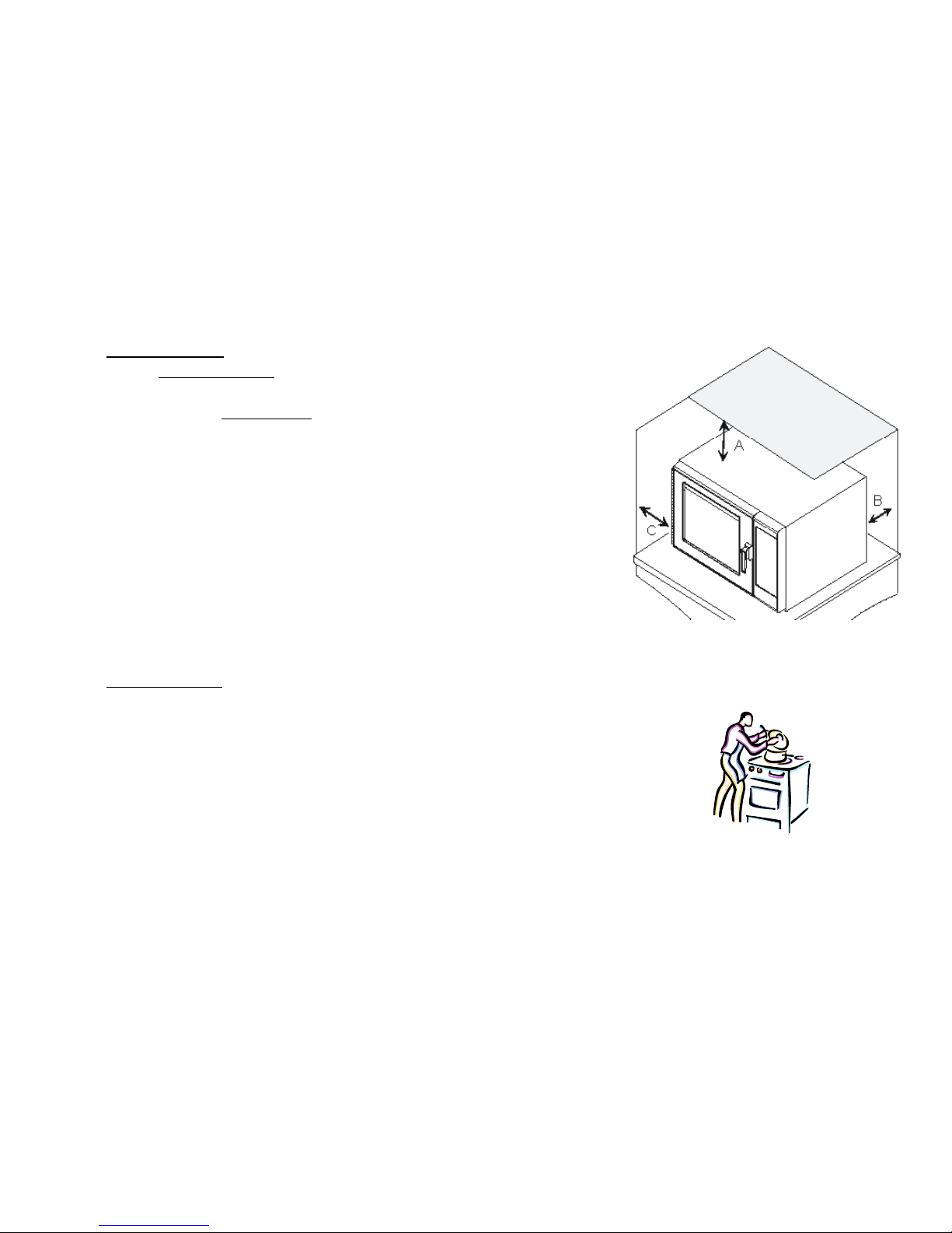
Oven Clearances
A—For North American (UL/CSA) models, allow at least 2” (5.1 cm) of
clearance around
top of oven. For International (50 Hz) models, allow at least 7” (17.8 cm)
of clearance
around top of oven. Proper air flow around oven cools electrical
components.
With restricted air flow, oven may not operate properly and life of
electrical parts is
reduced.
B—Allow at least 2 9/16” (6.5 cm) between air discharge on back of oven
and back wall.
C—Allow at least 1 1/4” (3 cm) of clearance around sides of oven.
Oven Placement
• Do not install oven next to or above source of heat, such as pizza oven
or deep fat fryer. This could cause microwave oven to operate
improperly and could shorten life of electrical parts.
• Do not block or obstruct oven filter. Allow access for cleaning.
• Install oven on level countertop surface.
• If provided, place warning label in a conspicuous place close to
microwave oven.
• Outlet should be located so that plug is accessible when oven is in
place.
INSTALLATION

Radio Interference
Microwave operation may cause interference to radio, television, or a similar oven. Reduce
or eliminate interference by doing the following:
• Clean door and sealing surfaces of oven according to
instructions in Care and Cleaning section.
• Place radio, television, etc. as far as possible from oven.
• Use a properly installed antenna on radio, television, etc.
to obtain stronger signal reception.
INSTALLATION
Earthing Instructions
Oven MUST be grounded.
The plug must be plugged into an outlet that is properly installed and grounded.
Consult a qualified electrician or servicer if grounding instructions are not completely
understood, or if doubt exists as to whether the oven is properly grounded.
Do not use an extension cord.
If the product power cord is too short, have a qualified electrician install a three-slot
receptacle.
This oven should be plugged into a separate circuit with the electrical rating as provided in
product specifications. When the combination oven is on a circuit with other equipment,
an increase in cooking times may be required and fuses can be blown.
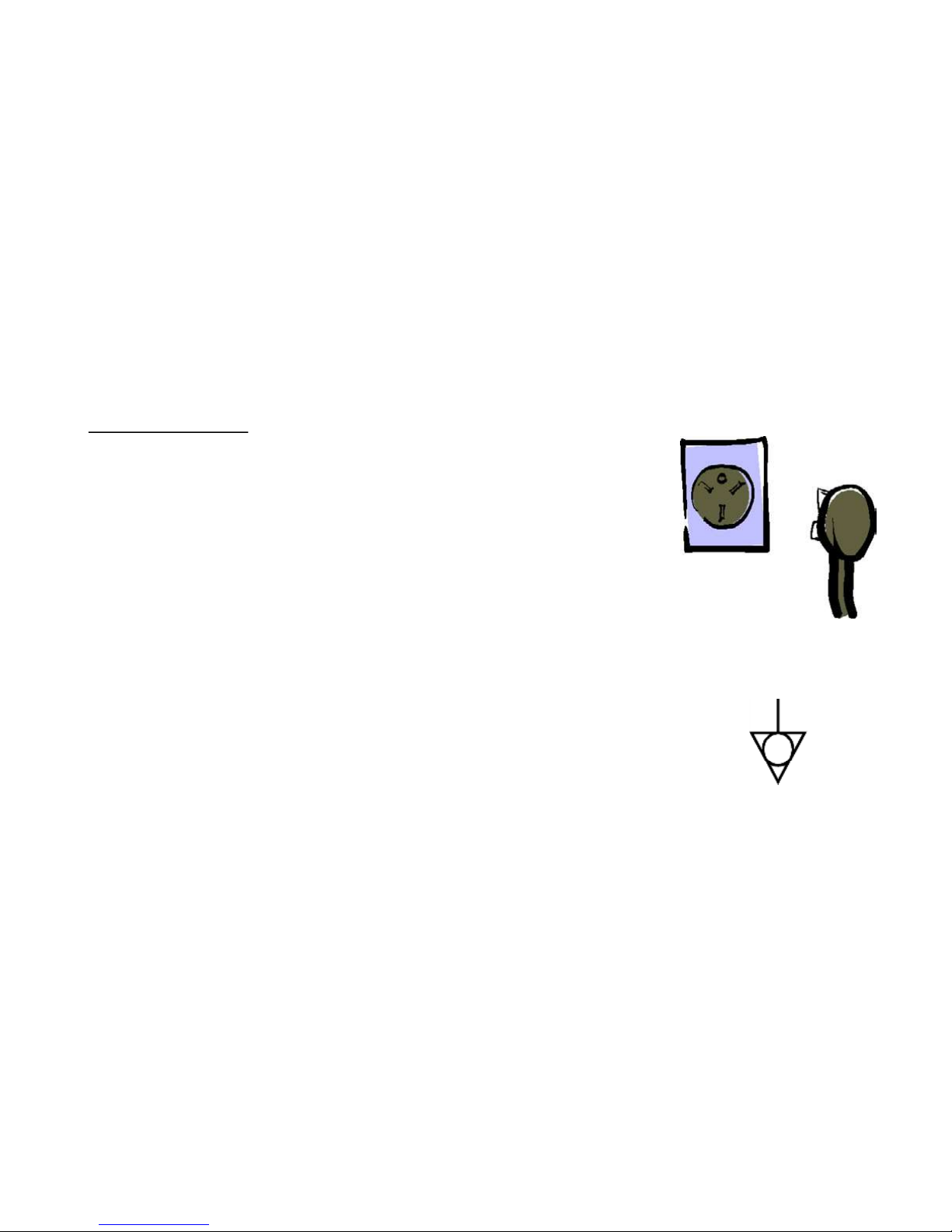
External Equipotential Earthing Terminal (export only)
Equipment has secondary earthing terminal. Terminal provides external earthing
connection used in addition to earthing prong on plug. Located on outside of oven back,
terminal is marked with symbol shown at right.
INSTALLATION
Microwave Ovens produce voltage up to -5000 volts DC!
Microwave Oven Capacitors can store high voltage even with oven unplugged!
Always discharge capacitors whenever checking high voltage components!
Always disconnect the power supply before servicing!
NEVER perform high voltage tests!
Wear appropriate eye and hand protection!
Follow safety precautions in Product and Service literature!
Test oven operation after repairs are completed!
SAFETY – MICROWAVE SERVICE
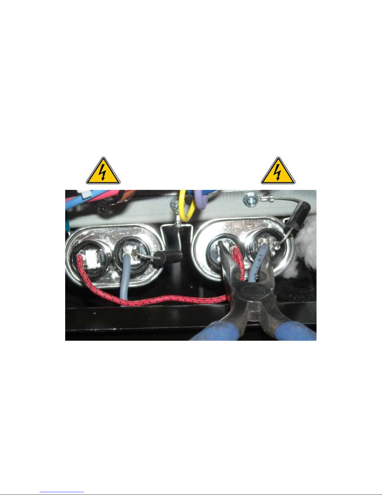
SAFETY - DISCHARGING CAPACITORS
ALWAYS DISCHARGE CAPACITORS BY SHORTING TERMINALS USING AN INSULATED TOOL(s)
CAPACITORS CAN HOLD HIGH
VOLTAGE EVEN WHEN POWER TO
OVEN IS DISCONNECTED!

FOOD AND DRUG ADMINISTRATION
DEPARTMENT OF HEALTH AND HUMAN SERVICES
SUBCHAPTER J – RADIOLOGICAL HEALTH
Sec. 1030.10 Microwave ovens.
. . . .
(v) One (the primary) required safety interlock shall prevent microwave radiation emission in excess of the
requirement of paragraph (c)(1) of this section; the other (secondary) required safety interlock shall prevent
microwave radiation emission in excess of 5 milliwatts per square centimeter at any point 5 centimeters or more
from the external surface of the oven. The two required safety interlocks shall be designated as primary or
secondary in the service instructions for the oven.
Precautions To Be Observed Before And During Servicing To Avoid Possible Exposure To Excessive
Microwave Energy
. . . .
(e) A Microwave leakage check to verify compliance with the Federal performance standard should be performed
on each oven prior to release to the owner.
NOTE: Other Government Agencies Have Same/Similar Standards
PART 1030 -- PERFORMANCE STANDARDS FOR MICROWAVE AND RADIO FREQUENCY EMITTING PRODUCTS
SAFETY – MICROWAVE EMISSIONS
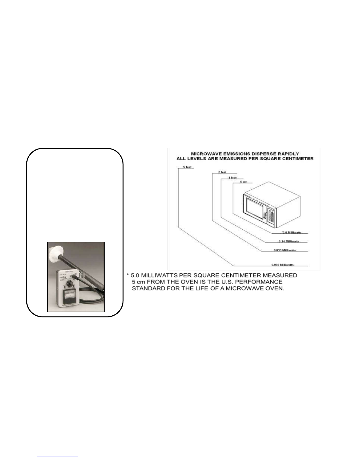
To ensure the unit does not emit
excessive microwave leakage and
meets Government Agency
guidelines, check the oven for
microwave leakage using the
Narda model 8100, 8200 Holaday
HI1500, HI1501, or Simpson 380M
leakage monitor as outlined in the
instructions. The maximum
leakage level allowed when
following those instructions is
5mw/cm2 .
SAFETY – MICROWAVE EMISSIONS
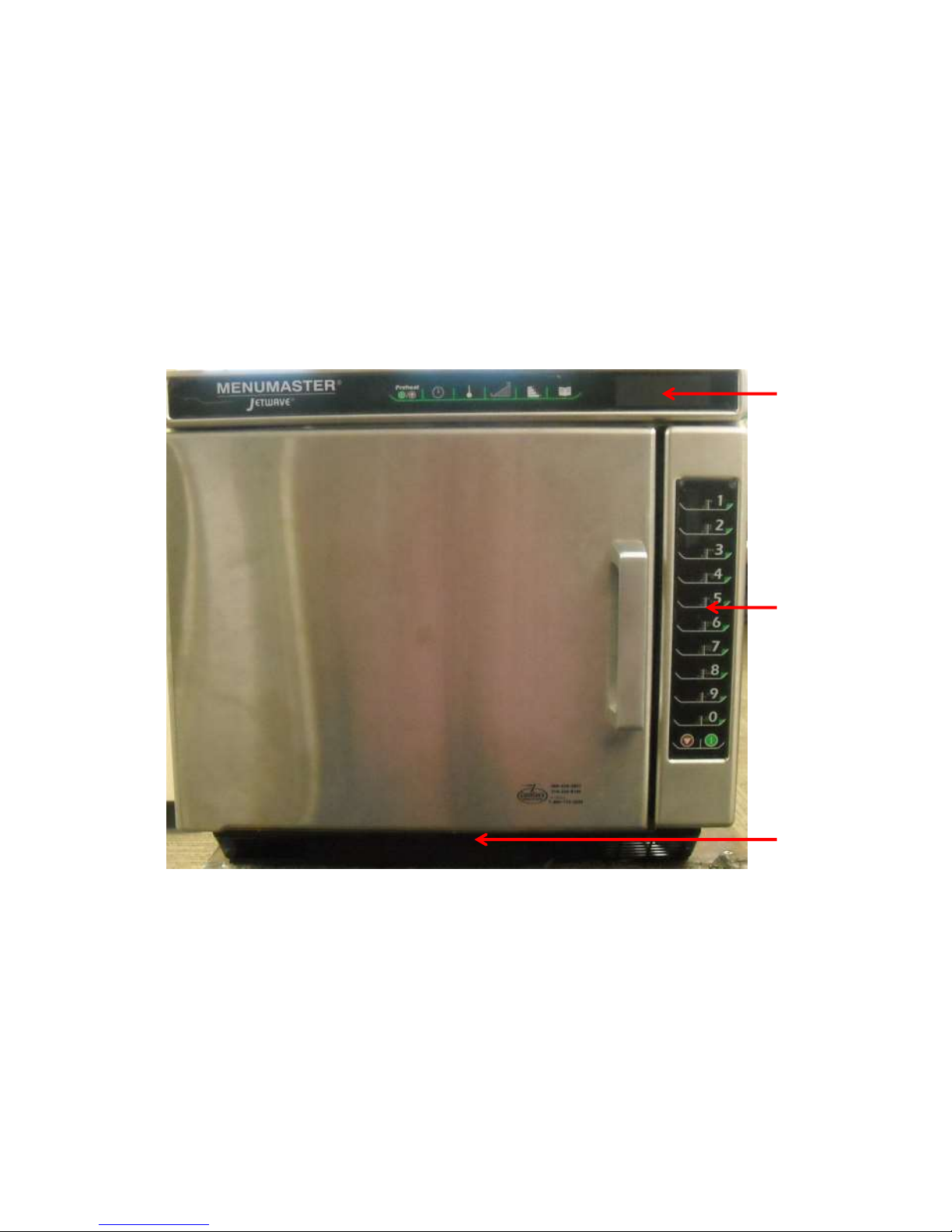
Front View
Top Touch
Panel
Side Touch
Panel
Removable
Air Filter &
Drip Pan
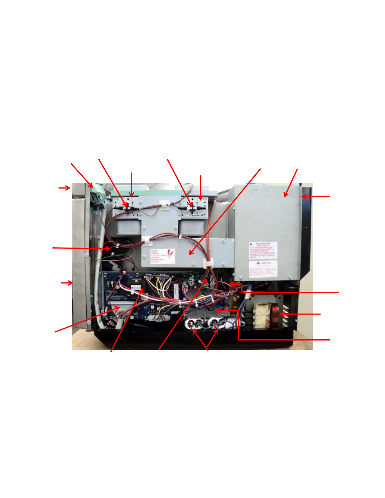
MAGNETRON
MAGNETRON
TCO
DISPLAY BOARD
INTERLOCK
SWITCHES
BLOWER
HOUSING
HV
TRANSFORMER
POWER
RELAY
MONITOR
RELAY BOARD
CAPACITORS
DIODES
HV BOARD
TRIACS (3)
SIDE
TOUCH PANEL
HARNESS,
DISPLAY TO
HV BOARD
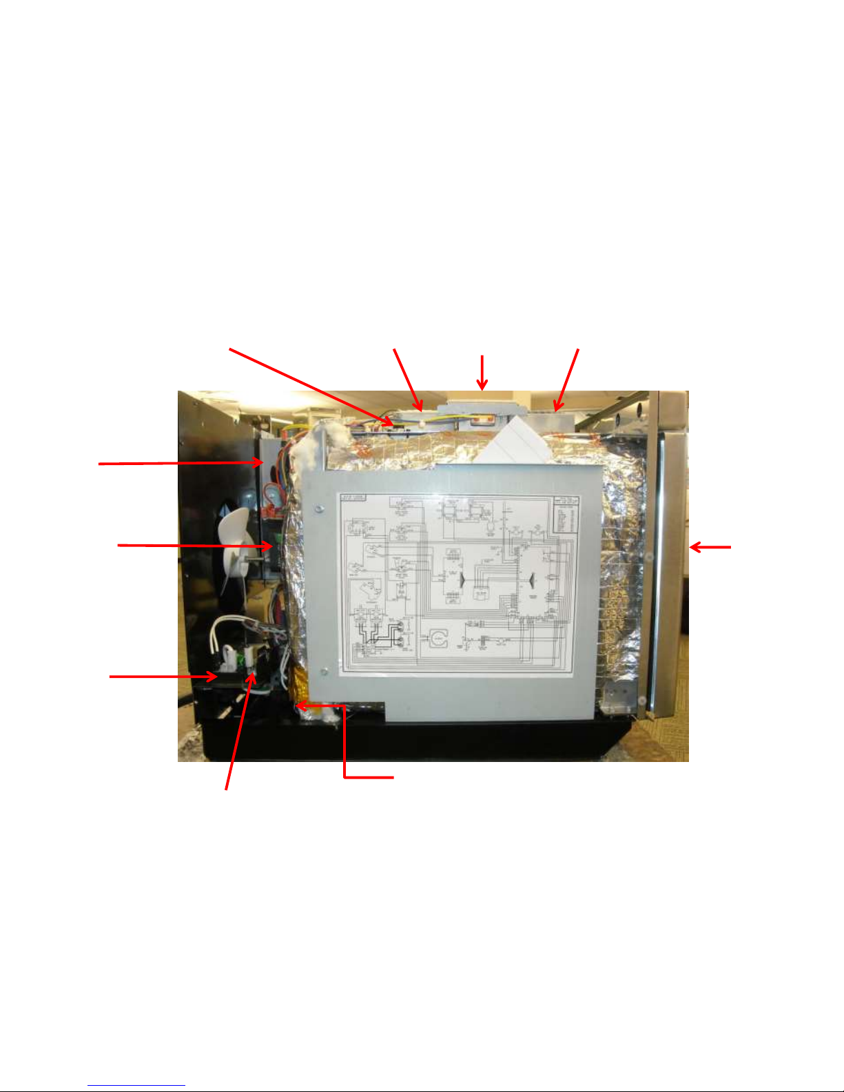
EXHAUST
MAGNETRON
MAGNETRON
TCO
AIR
DUCT
TOP
TOUCH PANEL
Right Side View
DOOR
ANTENNA
MOTOR
THERMAL
CUTOUT
FUSE & FUSE BLOCK
POWER
CORD
TERMINAL
BLOCK
CONVECTION
MOTOR
BLOWER
MOTOR
ANTENNA
GEAR
ANTENNA
GEAR
Left Side View
Oven/Cavity TCO
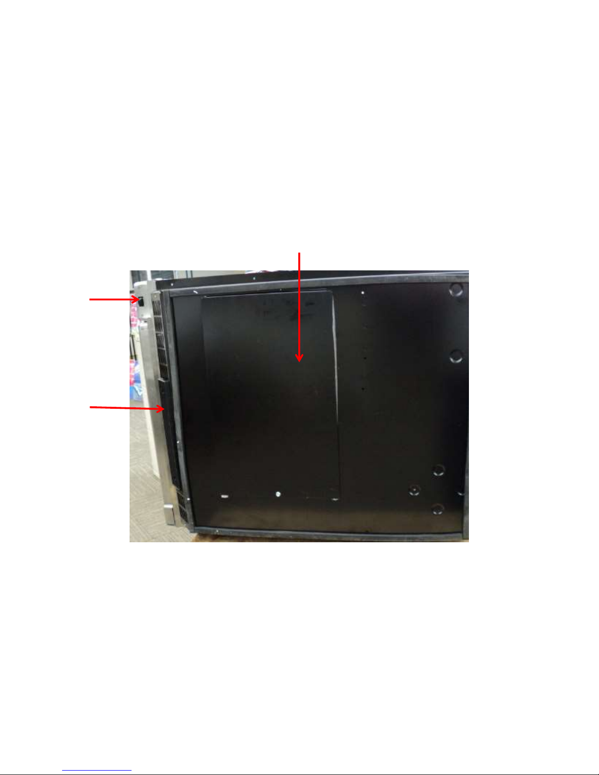
BOTTOM ANTENNA MOTOR ACCESS PANEL
USB PORT
REMOVABLE
AIR FILTER &
DRIP TRAY
Bottom View
ANTENNA
MOTOR
THERMAL
CUTOUT
31866P01
BLOWER
MOTOR
FRONT
ANTENNA
GEAR
HEATER
REAR
ANTENNA
GEAR
TEMP
SENSOR
THERMAL
CUTOUT
31866P01
WAVEGUIDE/
CAVITY
Top View
Note: Waveguide / Cavity is not replaceable
WAVEGUIDE/
CAVITY
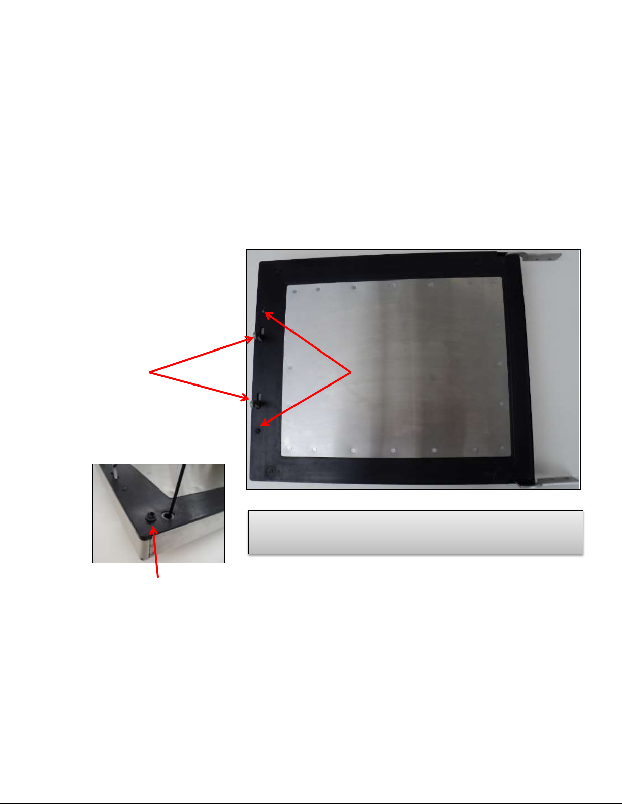
TO ACCESS INNER DOOR COMPONENTS:
Remove 2 Crosshead Screws, 4 hole plugs,
and 4 #15 Torx Screws (one in each corner)
Then outer door can be removed from
inner door panel assembly.
NOTE: If magnetized tools are not used, then it is recommended
to have the door removed and lying flat, otherwise, screws may
fall inside door weldment and be very difficult to retrieve.
LATCH ASSEMBLY
Screws
HOLE PLUG REMOVED
DOOR VIEW

DOOR VIEW
Two Components within the door assembly:
Door Hinge Spring found on the Upper Hinge Assembly (helps keep door open
for easier food removal) and the Door Latch Assembly
DOOR SPRING
DOOR LATCH ASSEMBLY
Mounting Screws
Upper Hinge Spring
ANTENNA COVER
RETAINING CLIP (4)
ANTENNA COVER
(Ceramic)
Remove the four retainer
clips while supporting the
antenna cover
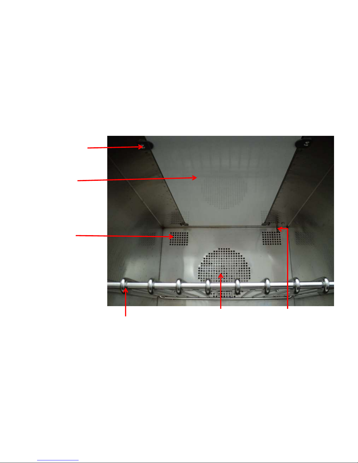
OVEN TEMP SENSOR
RTD
RACK
CONVECTION FAN
AIR INLET
OVEN EXHAUST (2)
ANTENNA/STIRRER – ACCESS
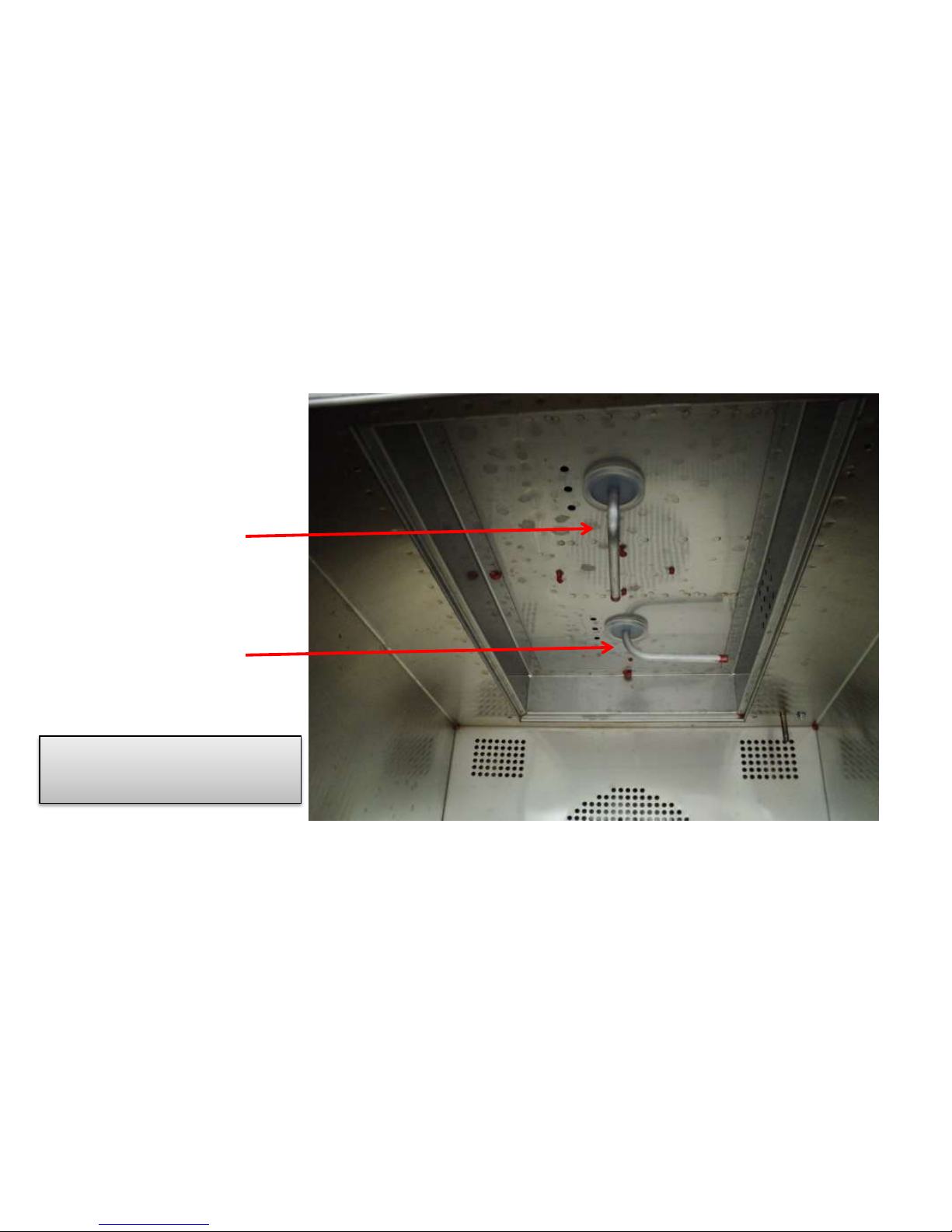
ANTENNA/STIRRER – Inside Cavity with Cover Removed
Note the positioning. Antennas
Should NEVER be in line with
each other
FRONT ANTENNA
REAR ANTENNA
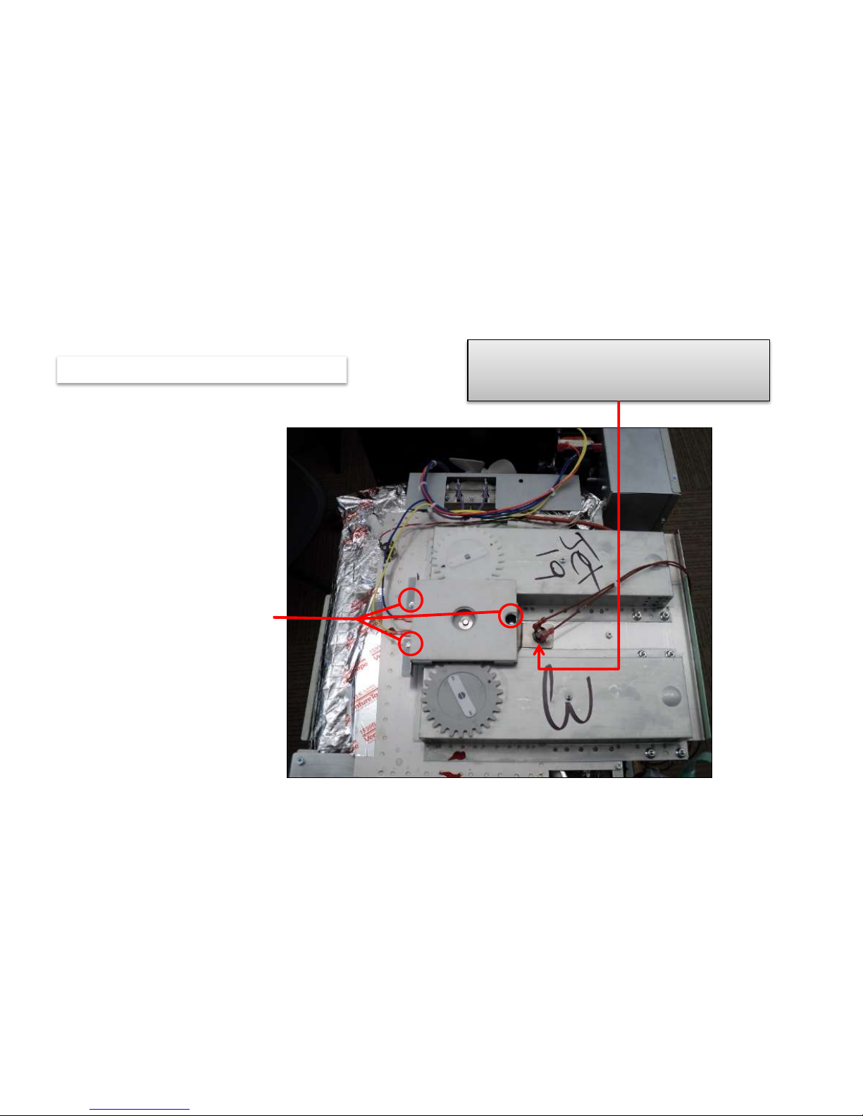
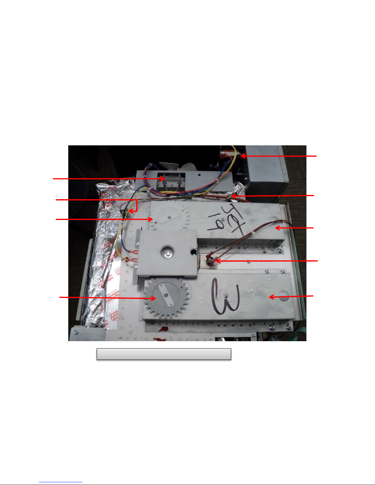
ANTENNA MOTOR – TESTING/REMOVAL
Disconnect wiring and
remove three securing screws
and lift off Antenna Motor Bracket
Note the position of top oven thermal
cutout mounting bracket. The TCO
should fit firmly to the top of the cavity
Terminal to Terminal - Approx. 12,000Ω
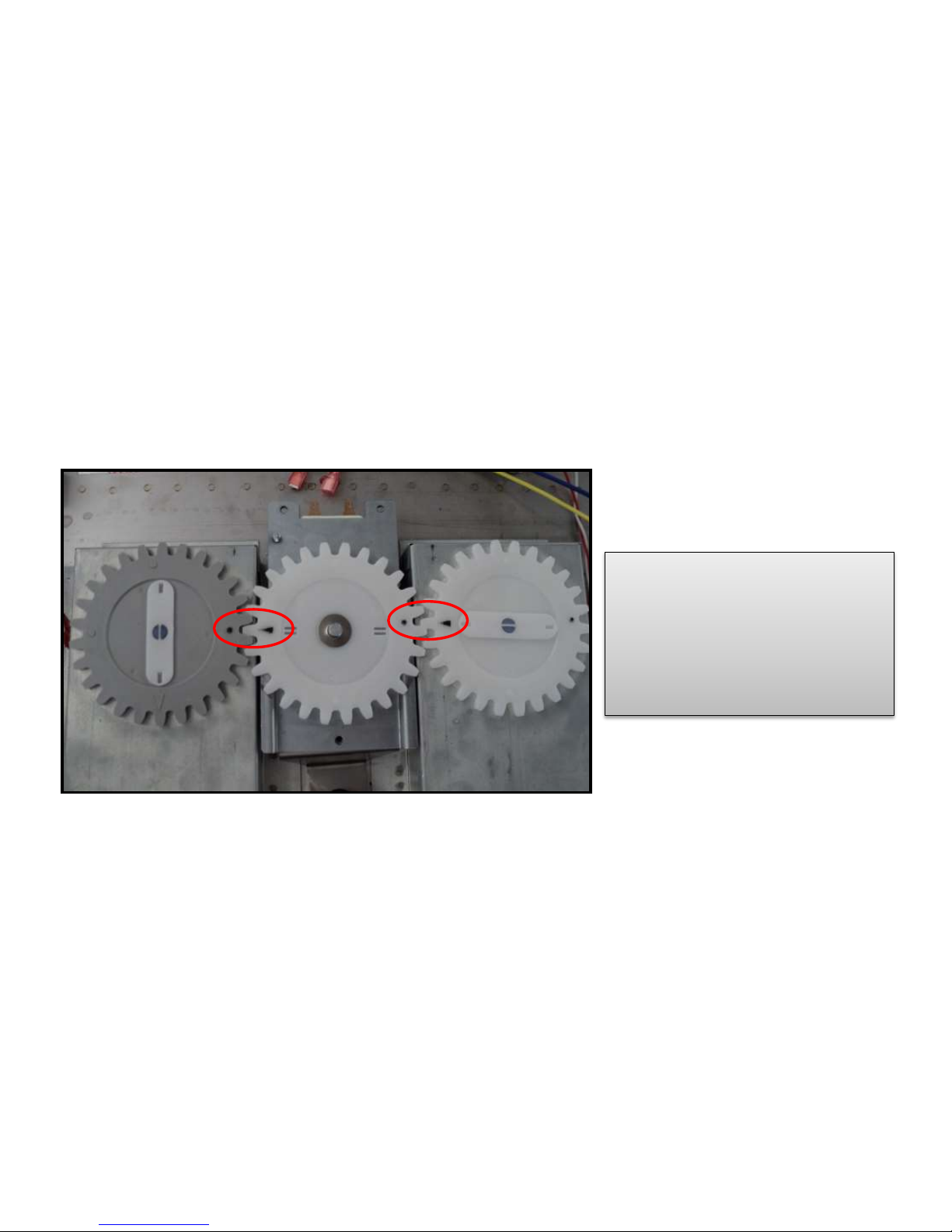
ANTENNA MOTOR – REMOVAL Cont’d
ENSURE PROPER ALIGNMENT
“Triangle to Dot to Triangle to Dot”
WHEN REASSEMBLING ANTENNA
SYSTEM, THIS ENSURES PROPER
ANTENNA POSITIONING INSIDE
THE OVEN CAVITY
 Loading...