

Page 1
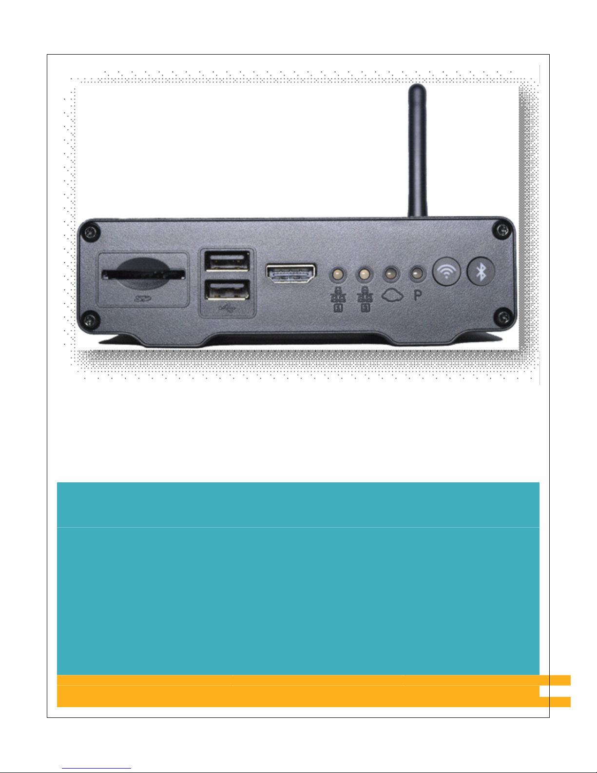
USER MANUAL FOR MF0200
GATEWAY BOX
VERSION 2.0
Page 2

User Manual for MF0200 Gateway Box
1 | Page
COPYRIGHT & TRADEMARKS
©2016 Mentor Graphics Corporation, all rights reserved. This document contains
information that is proprietary to Mentor Grap hics Corporation and may be duplicate d in
whole or in part by the original recipient for internal business purposes only, provided that
this entire notice appears in all copies.
FCC
STATEMENT
F
EDERAL COMMUNICATION COMMISSION INTERFERENCE STATEMENT
This equi pment has been tested and found to comply with the limits for a Class A digital
device, pursuant to part 15 of the FCC Rules. The se l imits are designed to provide
reasonable protection against harmful in terference when the equipment is operated in a
commercial environment. This equipment generates, uses, and can radiate radi o frequency
energy and, if not installed and use d in accordance with the instruction manua l, may cause
harmful interference to radio communic ations. Operation of this equipment in a residential
area is likely to cause harmful interference in which case the user will be required to
correct the interference at his own expense.
This equipment generates, uses and can radiate radio frequency energy and, if not installed
and used in accordance with the instructions, may cause harmful interference to radio
communications. However, there is no guarantee that interference will not occur in a
particular installation. If this equipment does cause harmful interference to radio or
television reception, which can be determined by turning the eq uipment off and on, the
user is encouraged to try to correct the interference by one of the following measures:
Reorient or relocate the receiving an
tenna.
Incr
ease the separation between the equipment and receive
r.
Conn
ect the equipment into an outlet on a circuit d i fferent from that to which th
e
rec
eiver is connected
.
Con
sult the dealer or an experienced radio/TV technician for help
.
FCC C
aution: To assure continued compliance, any changes or modifications not
expressly approved by the party responsible for compliance could void the user's authority
to operate this equipment. (Example - use only shielded interface cables when connecting
to computer or peripheral devices).
Page 3

User Manual for MF0200 Gateway Box
2 | Page
FCC Radiation E
xposure Statement
This transmitter must not be co-located or operating in conjunction with any other antenna
or transmitter.
CE
Mark Warning
This equipment is compliant with Class A of CISPR 32.In a residential environment this
equipment may cause radio interference.
Page 4

User Manual for MF0200 Gateway Box
3 | Page
BA
TTERY CAUTION: Danger of explosion if battery is incorrectly replaced. Replace
only with same or equivalent type recommended by the manufacturer. Do not discard used
batteries in to regular trash. These batteries need to be recycled according to the
manufacturer's instructions.
Page 5

User Manual for MF0200 Gateway Box
4 | Page
Table of Contents
Federal Communication Commission Interference Statement................................... ..... ..... ... ..... ..1
1. Introduction to MF0200 CSP Gateway.................................................................... ............... 6
1.1. CSP Gateway Specification............................................................................................7
1.1.1. Front View of CSP Gateway Device....................................................................................8
1.1.2. Back View Of CSP Gateway Device....................................................................................9
1.1.3. CSP Gateway Led Indicator Chart................................................................................10
2. Getting Started....................................................................................................................... 12
2.1. CSP Mobile Portal Application .................................................................................... 12
2.2. Connect the Gateway with Network............................................. ... ..... ... ..... ...... .. ...... ..12
2.2.1. Wired...................................................................................................................................12
2.2.3. Wireless...............................................................................................................................12
3. Initial Configurati on and Connection............................................................... ... ..... ..... ... .....13
3.1. Power up ............................................................... ...................................... ..................13
3.2. Login.............................................................................................................................14
3.3. Pairing & Connecting ................................. ..................................................................16
3.3.1. List Gateway Devices.........................................................................................................18
3.3.1.1. Gateway Device Info............................................................................. .. ........ 20
3.3.1.2. Update Network Settings................................................................................. 22
3.3.1.3. Ethernet Configuration:...................................................................................23
3.3.1.3.1. Ethernet Setup - DHCP...................................................................... ........ 24
3.3.1.3.2. Ethernet - Static Configuration ........................................ ..........................30
3.3.1.4. Wireless Configuration.................................................... ................................32
3.3.2. Scan Barcode ......................................................................................................................35
3.4. Firmware Update ............................................................. ................................... .. ........ 36
4. Add Peripheral Device...........................................................................................................37
4.1. Step 1 .......................................... .................................................................................. 38
4.2. Step 2 .......................................... .................................................................................. 39
4.3. Step 3 .......................................... .................................................................................. 40
4.4. Step 4 .......................................... .................................................................................. 44
5. VESA Mount 75mm * 75mm Information............................................................................47
6. Contact Us..................................... ... ..... ...... .. ...... ..... ... ..... ... ..... ..... ... ..... ...... .. ...... ..... ... .......... 47
Page 6

User Manual for MF0200 Gateway Box
5 | Page
Page 7

User Manual for MF0200 Gateway Box
6 | Page
1. INTRODUCTION TO MF0200 CSP GATEWAY
The MF0200 CSP gateway hardware is a clou d -connected high-performance computer
which is a component of Mentor Graphics’ Cloud Services Platform (CSP). This device
is fully managed from a flexible and extendable cloud-hosted backe nd. The MF0200
serves as an interface between any cloud- hoste d service and on premise devices
connected to the gateway via wired and/or wireless interfaces such as TV/Display
connected via HDMI cable to the gateway, USB devices (e.g. mouse, keyboard, camera,
etc.), network devices (e.g. pr inter, camera, etc.), and Wi-Fi connec t e d de vices (e.g. WiFi sensors, Wi-Fi actuators).
Page 8
User Manual for MF0200 Gateway Box
7 | Page
1.1. CSP GATEWAY SPECIFICATION
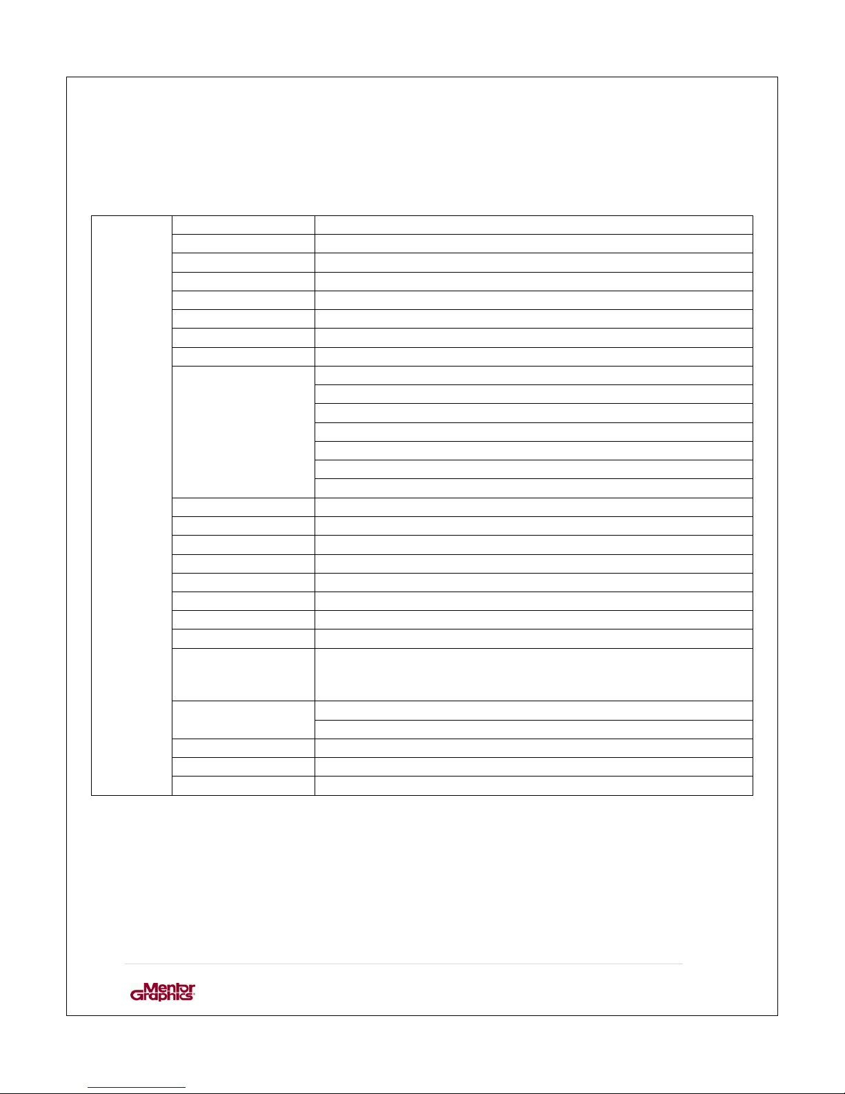
Following table shows specifications of the CSP gateway device.
CPU NXP i.MX6 quad-core 1.0GHz
Heatsink Yes
System RAM 2GB DDR3
eMMC 16GB
WiFi 802.11b/g/n 2.4G single-band
Bluetooth Yes
HDMI One (1) full-size HDMI
RTC Yes
One (1) | 6pin | wire-to-board connector
Pin1 – Red – UART4_TX
Pin2 – DCDC_5V
Pin3-GND
Pin4 – UART5_TX
Pin5-UART5_RX
UART (internal)
Pin6 – UART4_RX
NGFF Slot One (1) M.2 (NGFF socket 2) slot for storage SSD
USB (external) Four (4) Host | standard-a receptacle
USB (internal) One (1) 1*OTG | 5 pin | wire-to-board connector
SD Card Slot One (1) full size SD card slot
Ethernet LAN Two (2) Gigabit LAN for RJ45
EEPROM 2Kbit EEPROM
GPIO One (1) 10pins | wire-to-board connector
Power / DC Jack 12V / 2A (24W) wall-mount type of adaptor | US-type plug
LEDs Two (2) LAN indicators
One (1) Cloud connection indicator
One (1) Peripheral connection indicator
Reset (RR)
Buttons
Factory reset (FR)
Antenna (external) One (1) WiFi/BT | connector is SMB type
Board Dimensions 129.0 (L) * 89.6 (W) mm
RoHS Yes
Page 9
User Manual for MF0200 Gateway Box
8 | Page
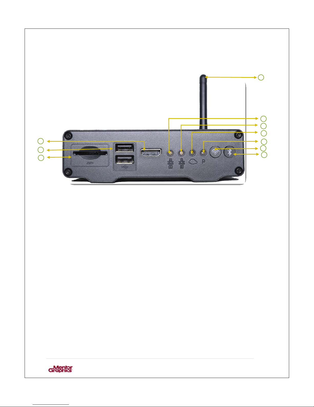
1.1.1. FRONT VIEW OF CSP GATEWAY DEVICE
1. Wi-Fi Antenna.
2. LED: Ethernet 0 interface activity indicator
3. LED: Ethernet 1 interface activity indicator
4. LED: Cloud LED
5. LED: Peripherals LED
6. Wi-Fi Indicator
7. Bluetooth Indicator
8. HDMI out-port
9. USB Ports
10. SD card slot
2
3
4
5
6
8
10
9
Page 10
User Manual for MF0200 Gateway Box
9 | Page
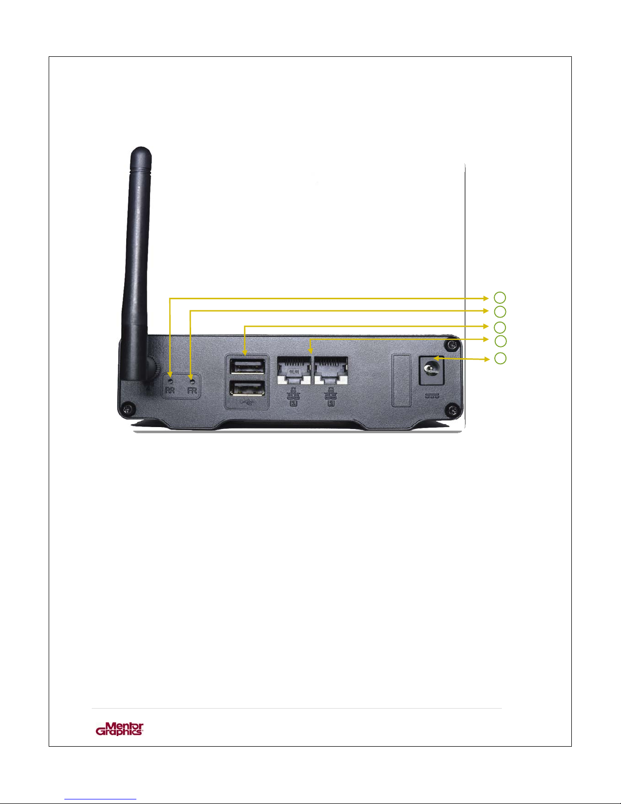
1.1.2. BACK VIEW OF CSP GATEWAY DEVICE
1. RR: Reset
2. FR: Factory Reset
3. USB ports
4. Ethernet 0 and Ethernet 1 port
5. Power Supply
1
4
2
3
5
Page 11
User Manual for MF0200 Gateway Box
10 | Page
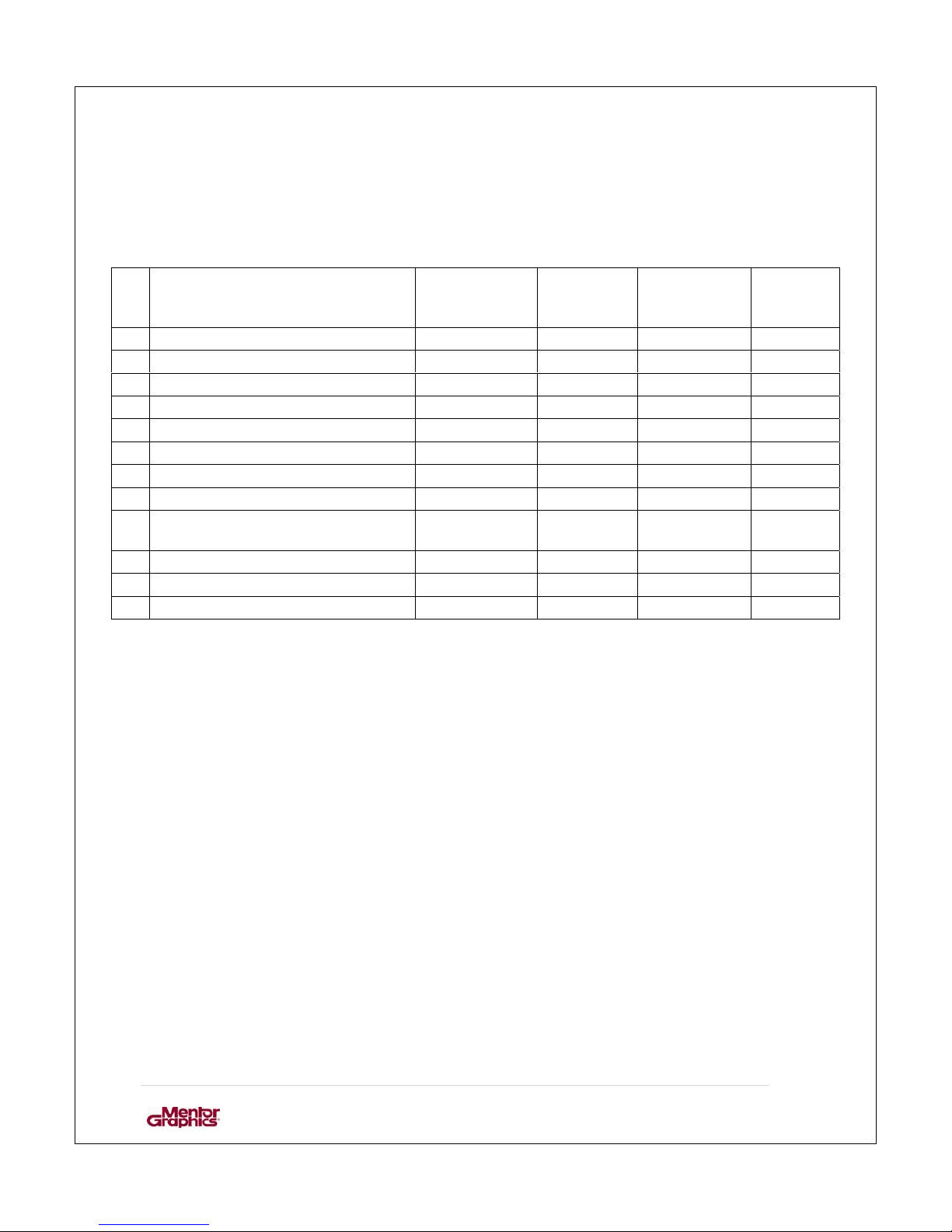
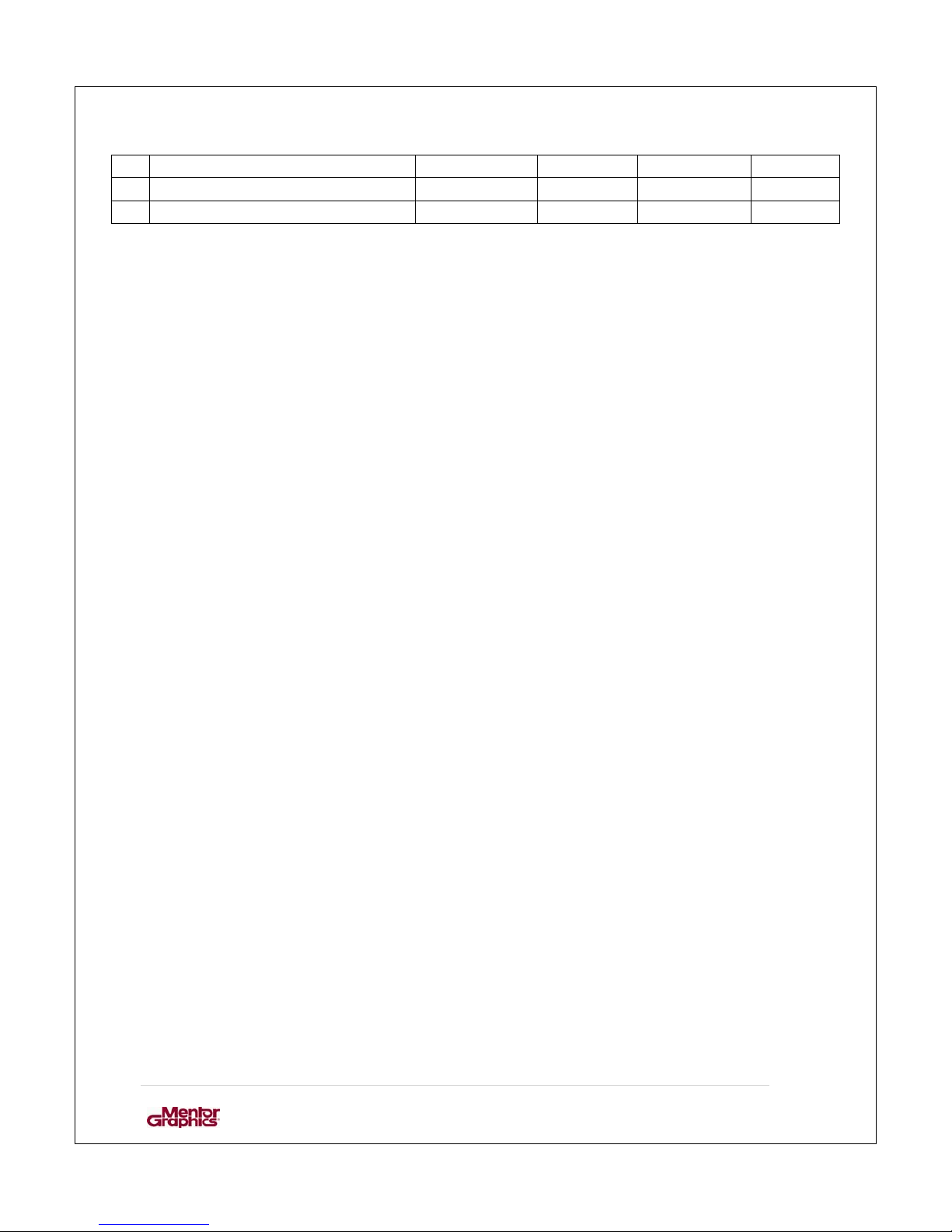
1.1.3. CSP GATEWAY LED INDICATOR CHART
Following table shows how the LED lights indicate the o peratio ns being performed on
the CSP gateway device.
no. CSP Box State GREEN
Peripherals
LED
RED
Peripherals
LED
GREEN
Cloud
LED
RED
Cloud
LED
1 Power On ON OFF ON OFF
2 Kernel Booting Heartbeat OFF OFF OFF
3 Kernel Booted Successfully ON OFF OFF OFF
4 CSP System Starting ON OFF Heartbeat OFF
5 CSP System Signaling Connecting ON OFF Timer OFF
6 CSP System Signaling Connected ON OFF ON OFF
7 CSP System applying patch ON OFF Heartbeat Heartbeat
8 CSP System updating firmware ON ON ON ON
9 CSP System No Configuration
Object
ON OFF OFF ON
10 CSP System Fatal Error ON OFF OFF Timer
11 CSP Box Rebooting Heartbeat OFF Heartbeat OFF
12 CSP System Error updating OFF Heartbeat OFF Heartbeat
Page 12
User Manual for MF0200 Gateway Box
11 | Page
firmware
13 CSP System Error applying patch ON OFF OFF Heartbeat
14 CSP System firmware update done Heartbeat Heartbeat Heartbeat Heartbeat
Page 13

User Manual for MF0200 Gateway Box
12 | Page
2. GETTING STARTED
To setup the gateway, you require:
2.1. CSP MOBILE PORTAL APPLICATION
The basic system requirements to set up the gateway device are:
1. Android device which ope ra t e s o n android version 5.1 or above.
2. CSP Admin Console App installed on th e device. If the user does not have the ap p;
it can be downloaded from the CSP Admin Portal
.
a. Aft er downloading and installing the application the user needs to log in
using the credentials through which they access the CSP web portal.
b. If the user does not have the credentials for CSP Web portal then he/she can
request for credentials through CSP web Portal as mention in Section no.
1.2 “Apply for Account” in the document “CSP Admin Portal R7”.
2.2. CONNECT THE GATEWAY WITH NETWORK
Gateway device can be connected through both wireless a nd wir e d networks.
2.2.1. WIRED
1. DHCP.
2. Static.
2.2.3. WIRELESS
1. DHCP.
Page 14

User Manual for MF0200 Gateway Box
13 | Page
3. INITIAL CONFIGURATION AND CONNECTION
3.1. POWER UP
1. Attach the provided antenna to the gateway: Screw on antenna to the provided
socket on the gateway. The antenna can be rotated and angled so it can be
aligned in any installation position.
2. In case of wired connection: Attach the LAN wire to the gateway device
3. Connect the provided power adaptor to the gateway
4. Wait for about one minute to allow the gateway to fully boot itself
5. Login to the CSP portal using your mobile device (smartphone) – see chapter
3.2
Page 15
User Manual for MF0200 Gateway Box
14 | Page
3.2. LOGIN
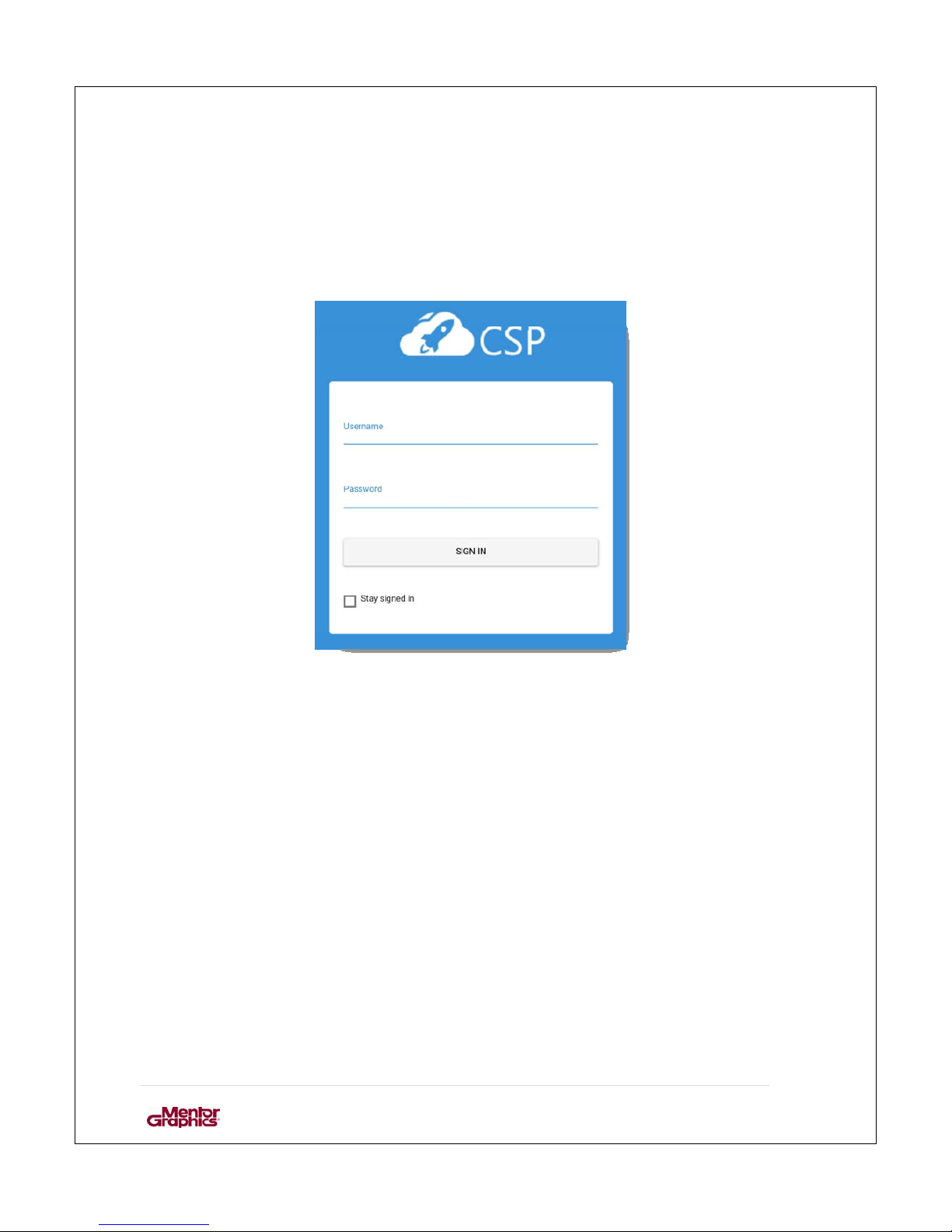
Launch the CSP mobile setup application on your mobile device and login into
the CSP mobile portal by providing a valid username and password.
Figure 1: Login
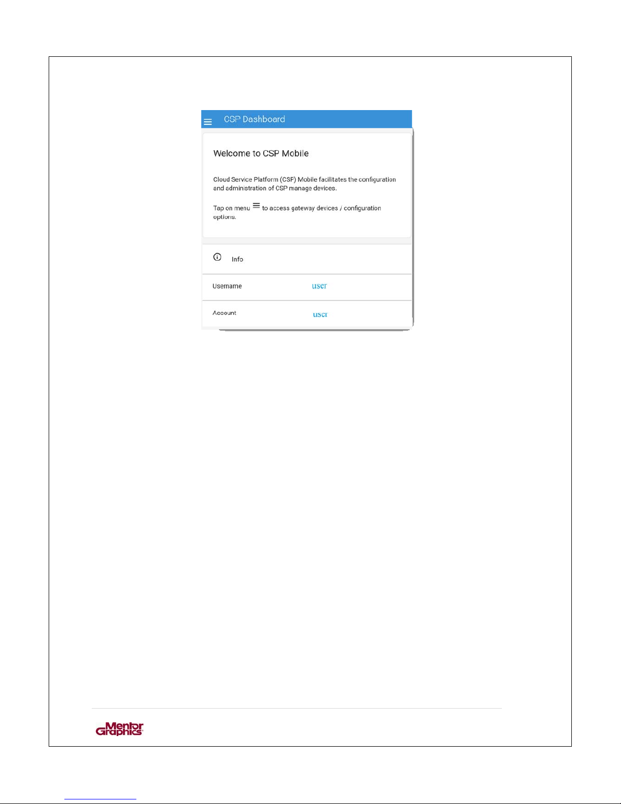
Enter Credentials provided to you by the CSP administrator to login. Following
screen would appear after you laun ch the CSP mobile setup application
Page 16
User Manual for MF0200 Gateway Box
15 | Page
Figure 2: Home screen
Page 17
User Manual for MF0200 Gateway Box
16 | Page
3.3. PAIRING & CONNECTING
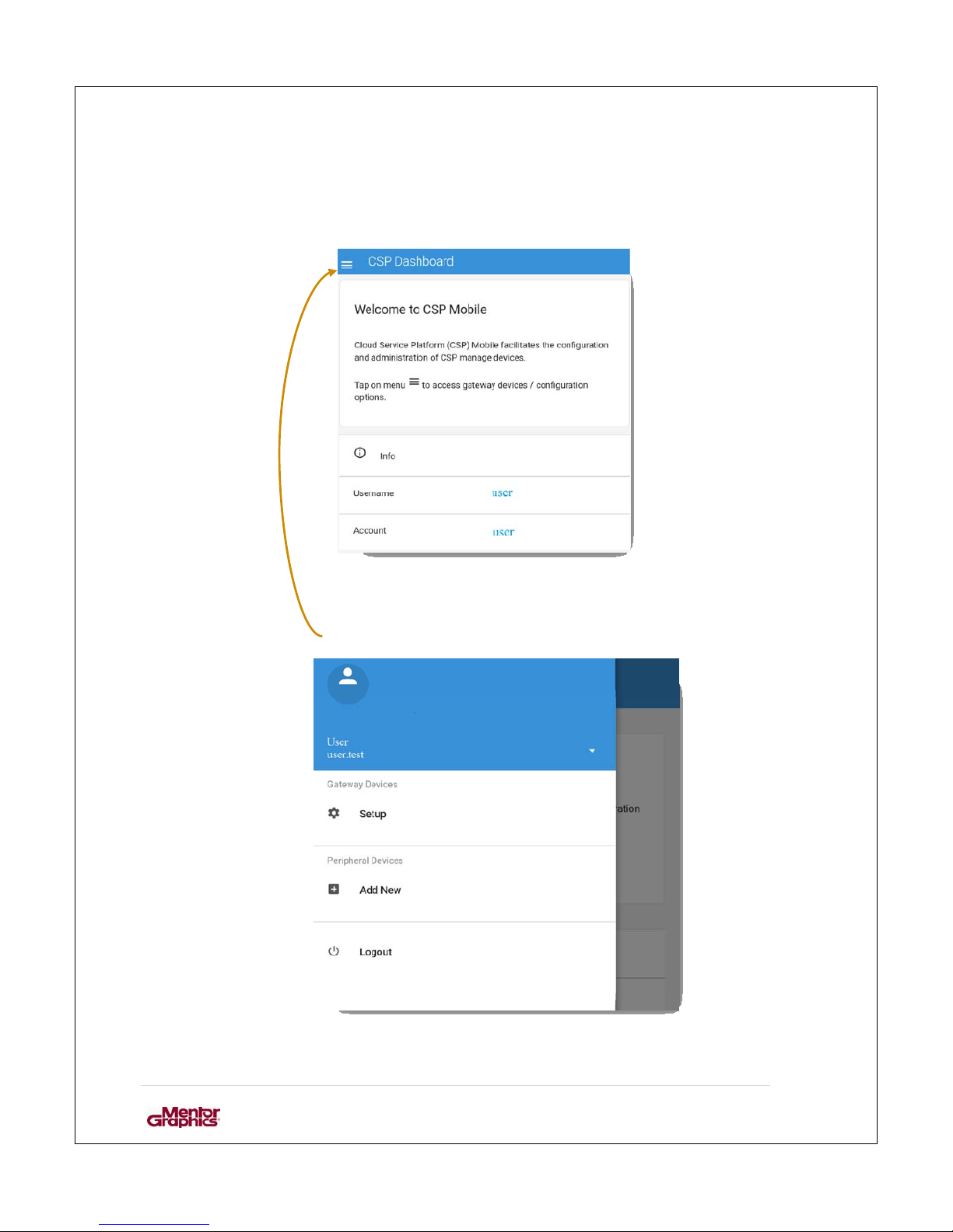
To pair the gateway device it is nee d ed to go to the dashboard and setup the de vice.
Figure 3: Home screen
After clicking the menu button the Dashboard can be seen.
Figure 4: Dashboard
Page 18
User Manual for MF0200 Gateway Box
17 | Page
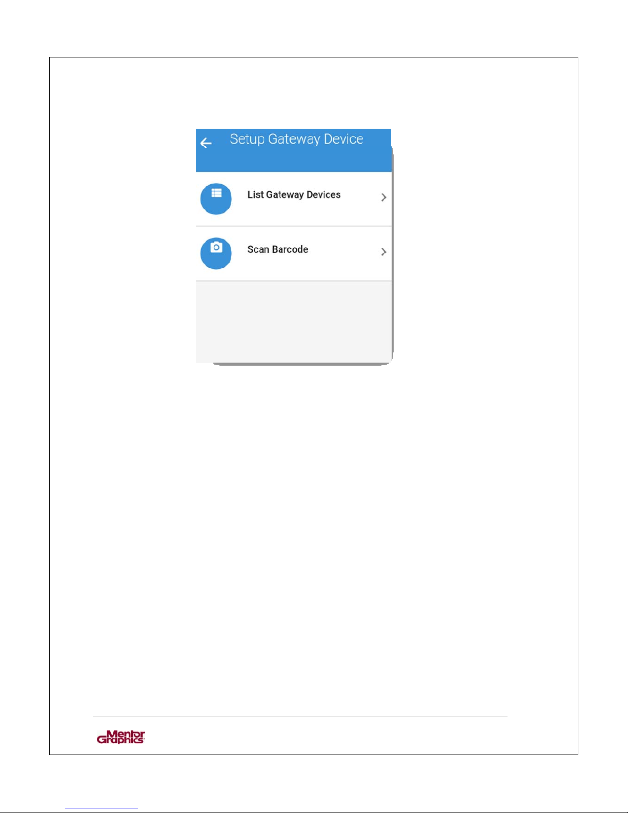
Click on setup to pair and configure the box.
Figure 5: Two ways of setting up a gateway device
The gateway device can be selected in two ways – by selecting the gateway from a
drop-down list or by scanning t he barcode located on the back of t he ga teway. The list
provides the IDs of gateway devices available, user can search the device manually.
Alternatively, the user can scan the “Gatew ay Barcode” to choose the device directly.
Prerequisite:
The device has already been provisioned on CSP backend
Page 19
User Manual for MF0200 Gateway Box
18 | Page
3.3.1. L
IST GATEWAY DEVICES
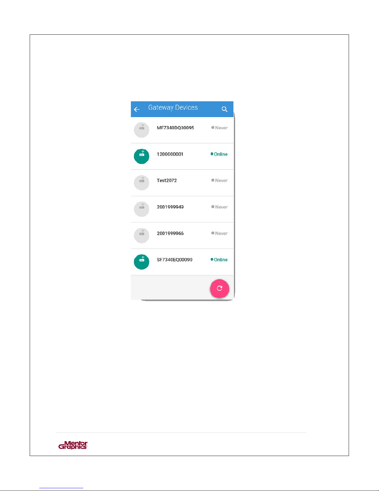
List of all the gateway devices provisioned with particular account will be displayed.
Figure 6: List of gateway devices
After choosing the gateway, application requests to turn on the Bluetooth on the
mobile device (smartphone) if it already has not been enabled. After selecting the gateway
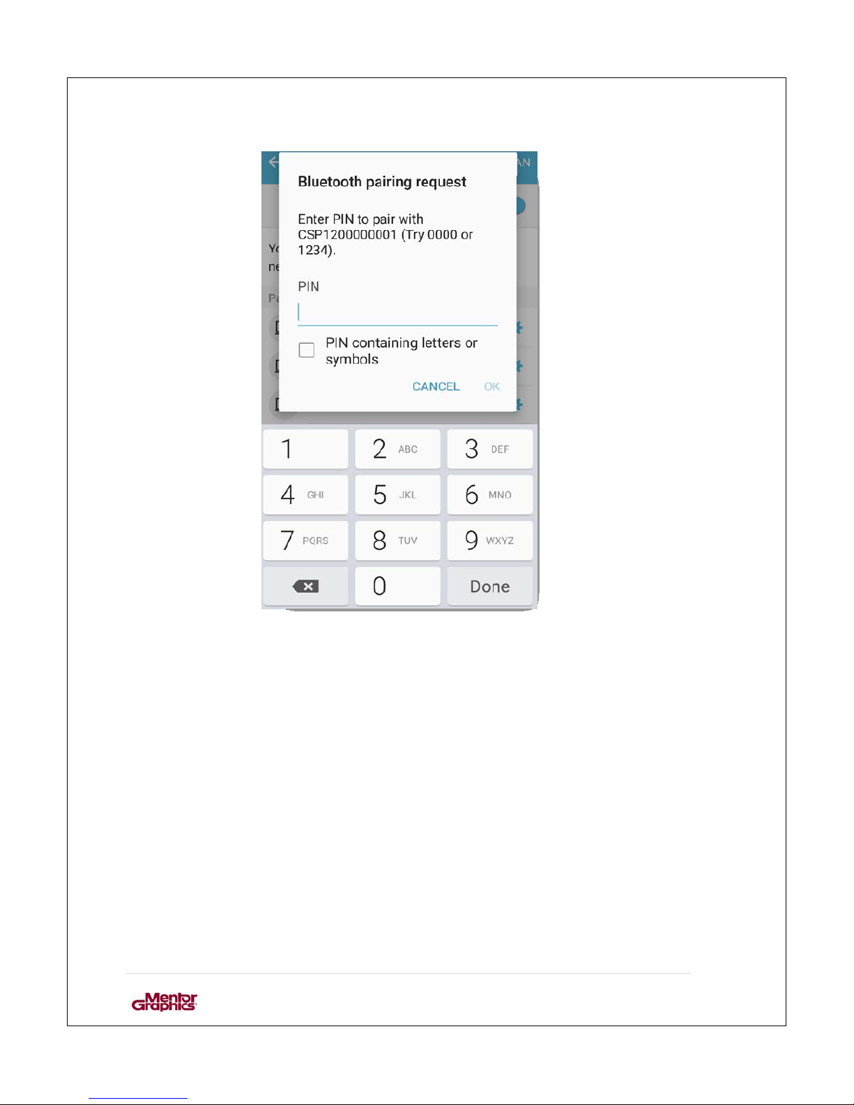
it following screen would appear to pair t he mobile device with CSP gateway device.
Page 20
User Manual for MF0200 Gateway Box
19 | Page
Figure 7: Enter pin for pairing
Enter the pin of CSP gateway device provided to you by the CSP administrator.
Page 21
User Manual for MF0200 Gateway Box
20 | Page
3.3.1.1. Gateway Device Info
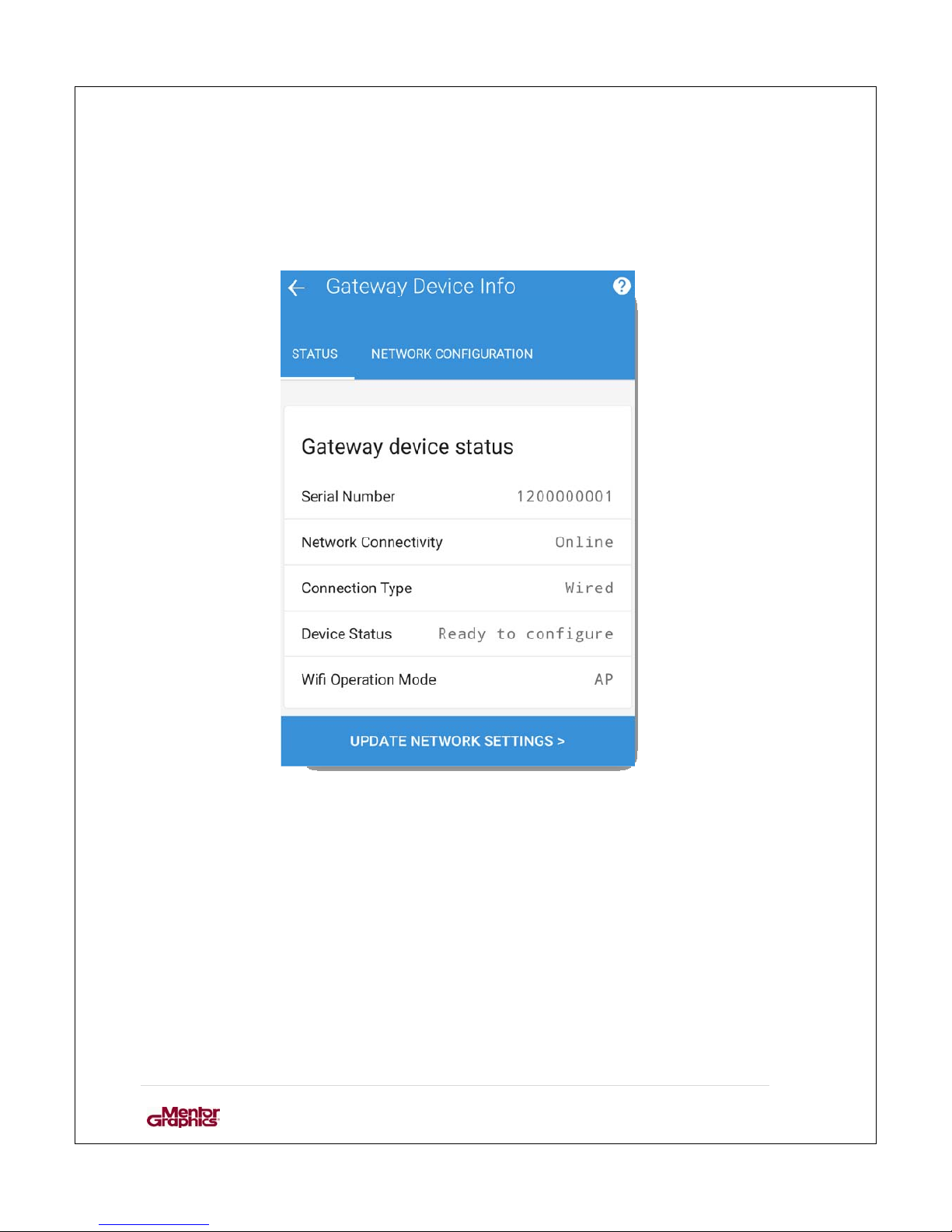
After authentication the following screen would appea r with information regarding the
selected CSP gateway device. This shows the current settings of the CSP Gateway device.
Figure 8: Gateway Device Info- status
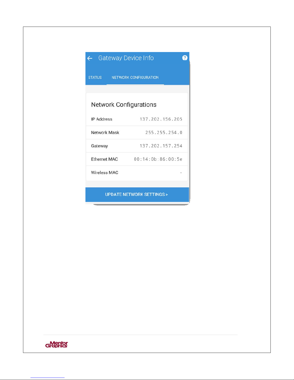
To see the network configurations of the CSP ga te wa y device select “Network
Configurations” tab.
Page 22
User Manual for MF0200 Gateway Box
21 | Page
Figure 9: Gateway Device Info- Network Configuration
Page 23
User Manual for MF0200 Gateway Box
22 | Page
3.3.1.2. Update Network Settings
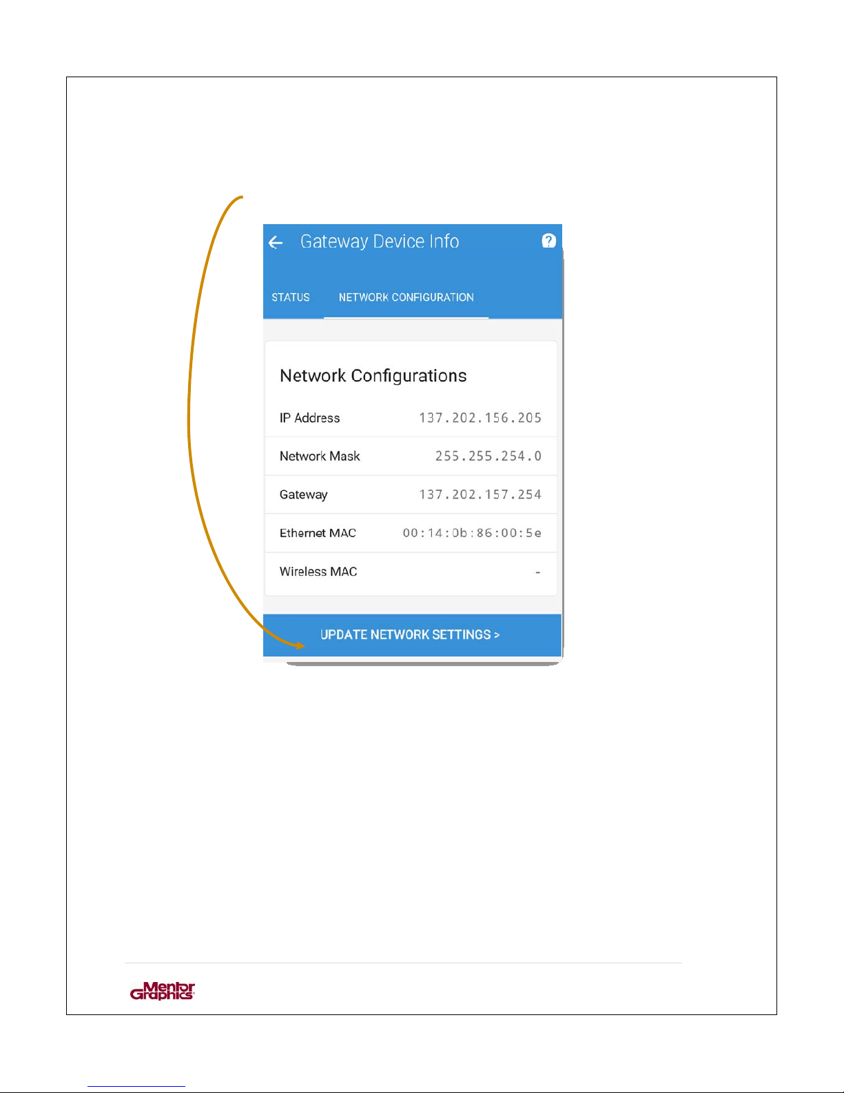
Click on Update Network Settings to change the network settings.
Figure 10: Update Network Settings.
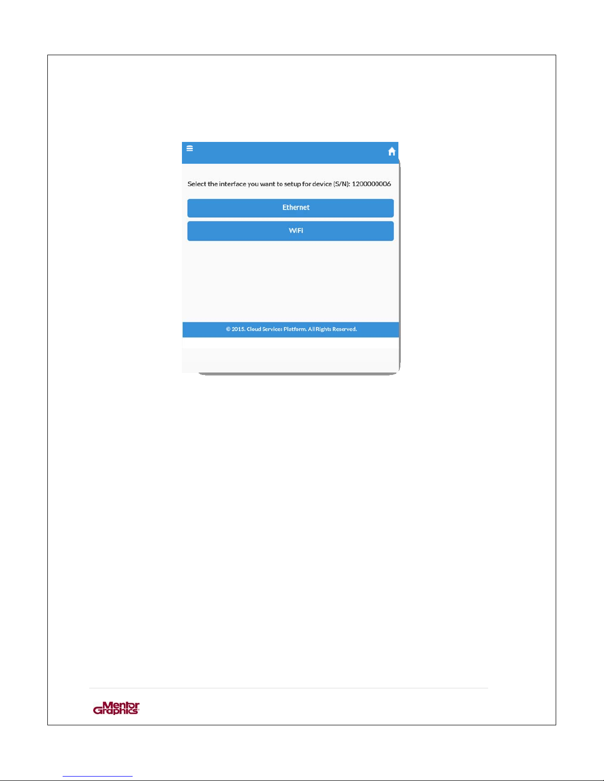
After selecting “Update Network Settings” new screen woul d appear that allows th e user to
choose the networking interface. In this case it is “Ethernet”.
Page 24
User Manual for MF0200 Gateway Box
23 | Page
3.3.1.3. Ethernet Configuration:
Figure 11: Choose the network interface
After choosing Ethernet click “NEXT”.
Page 25
User Manual for MF0200 Gateway Box
24 | Page
3.3.1.3.1. Ethernet Setup - DHCP
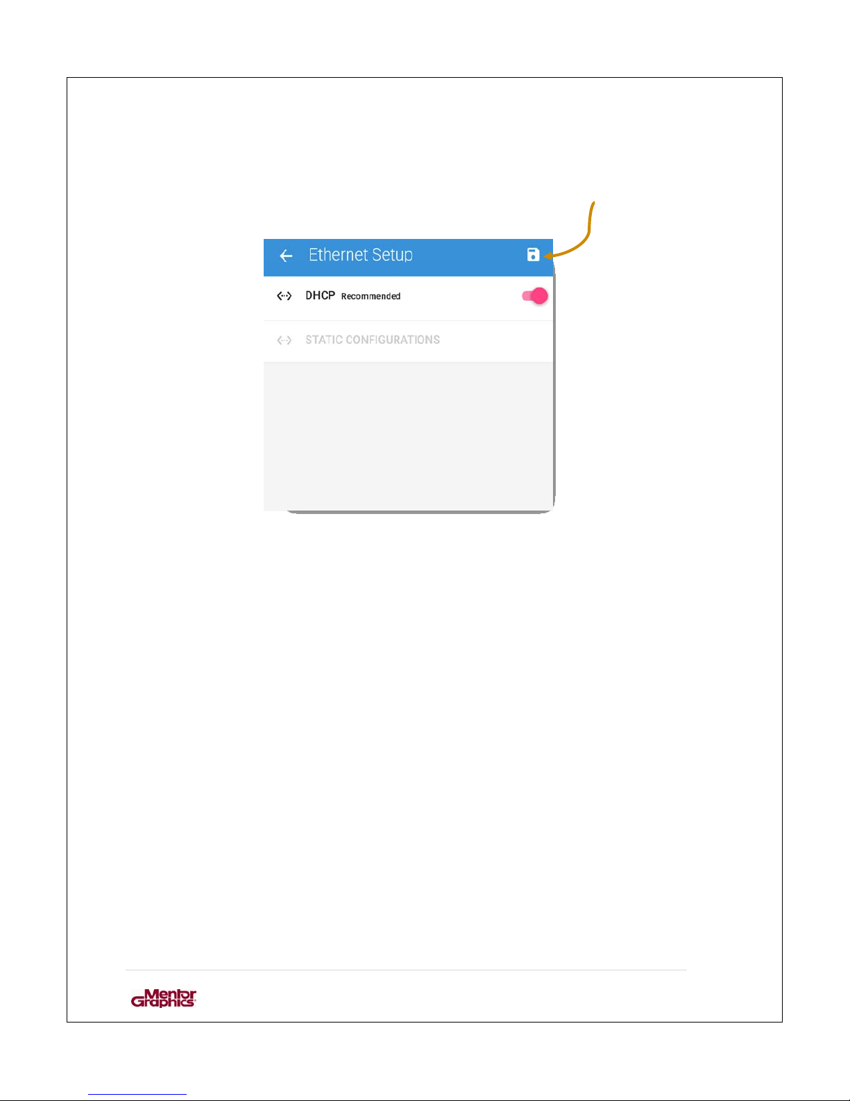
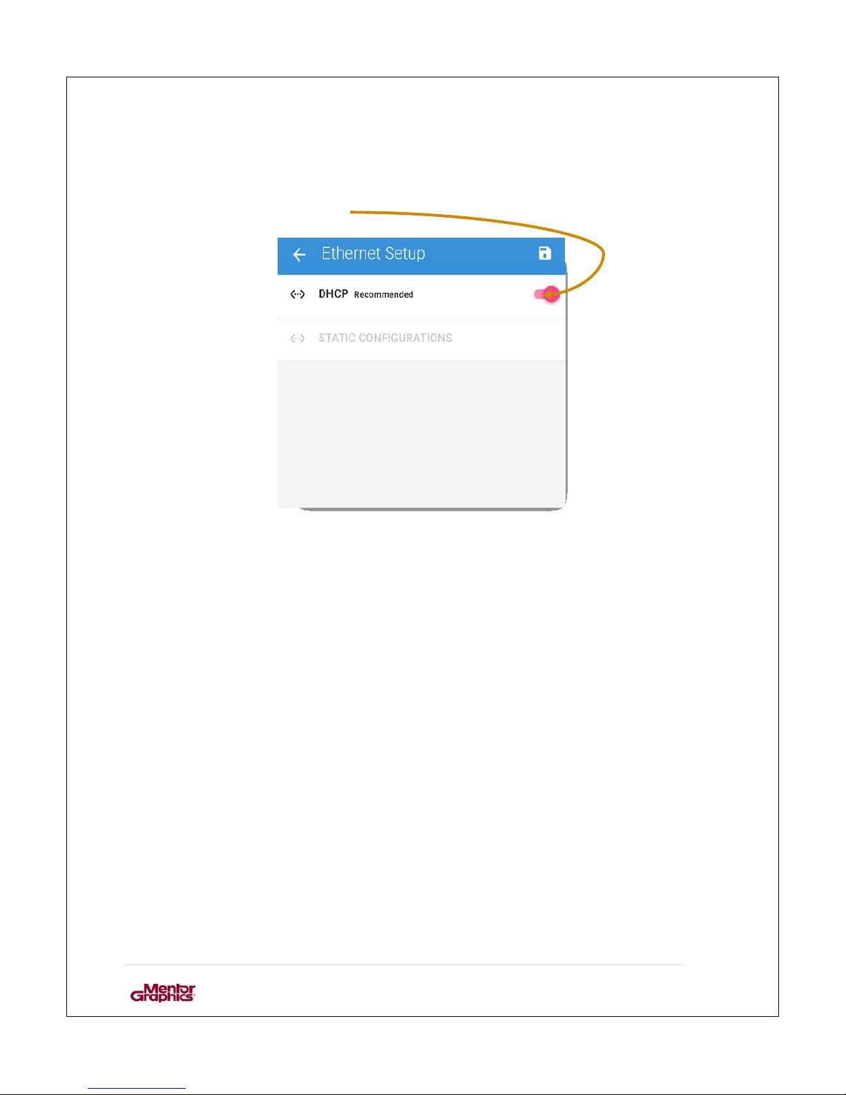
Ethernet can be setup to either DHCP or Static configuration. Click on save button to
select DHCP.
Figure 12: Ethernet Setup
Page 26
User Manual for MF0200 Gateway Box
25 | Page
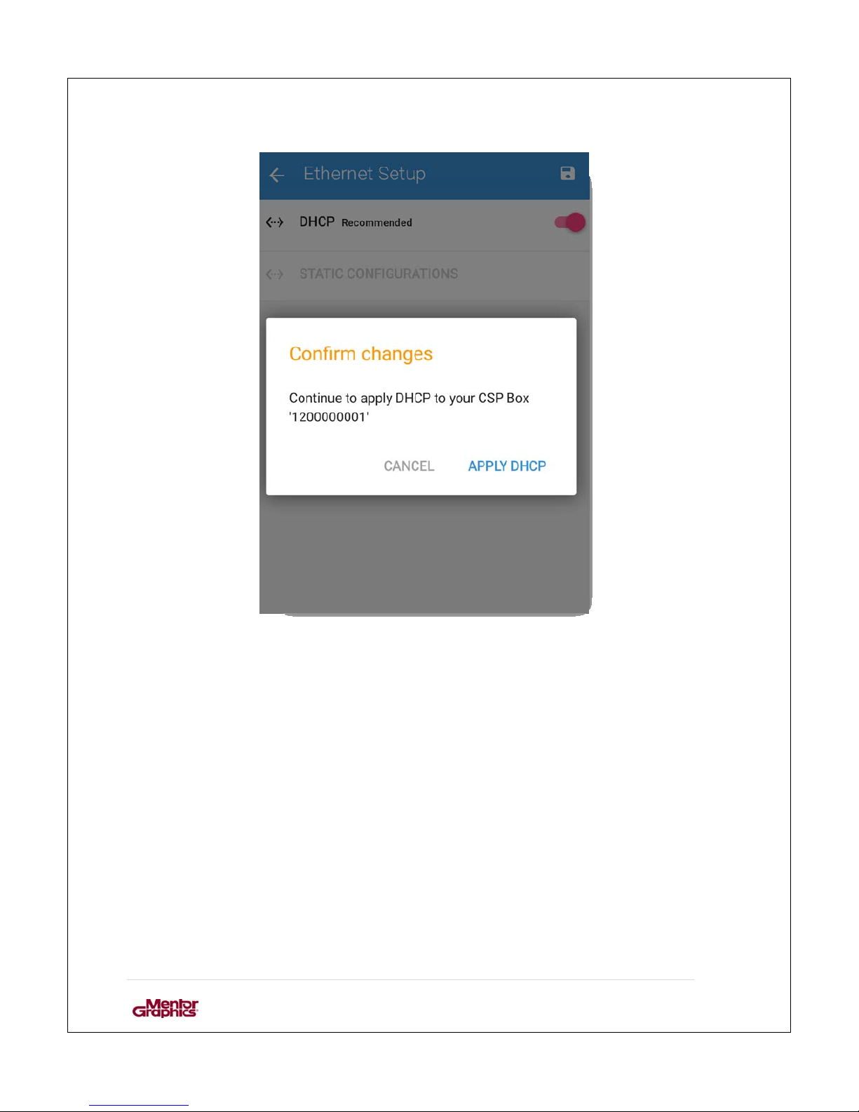
Figure 13: Confirm Changes to Setting.
Select “Apply DHCP” to confirm the selection.
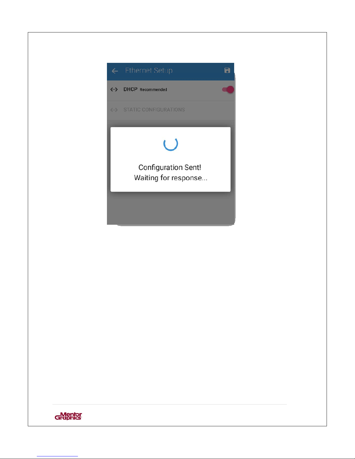
After DHCP settings; following window appears to confirm that configuration is sent.
Page 27
User Manual for MF0200 Gateway Box
26 | Page
Figure 14: Configuration sent
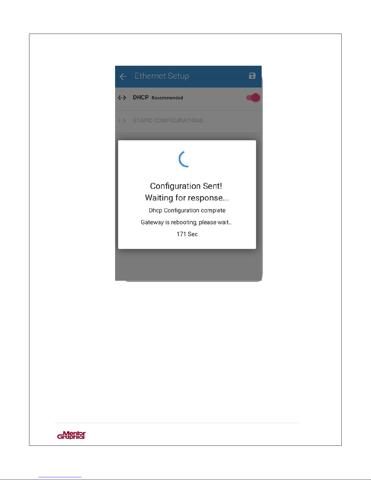
After configurations are sent the CSP gateway device is automatically rebooted.
Page 28
User Manual for MF0200 Gateway Box
27 | Page
Figure 15: Rebooting the device.
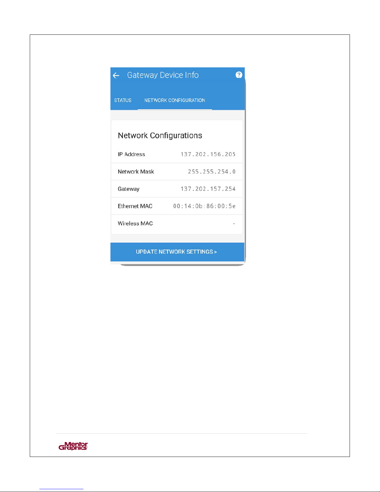
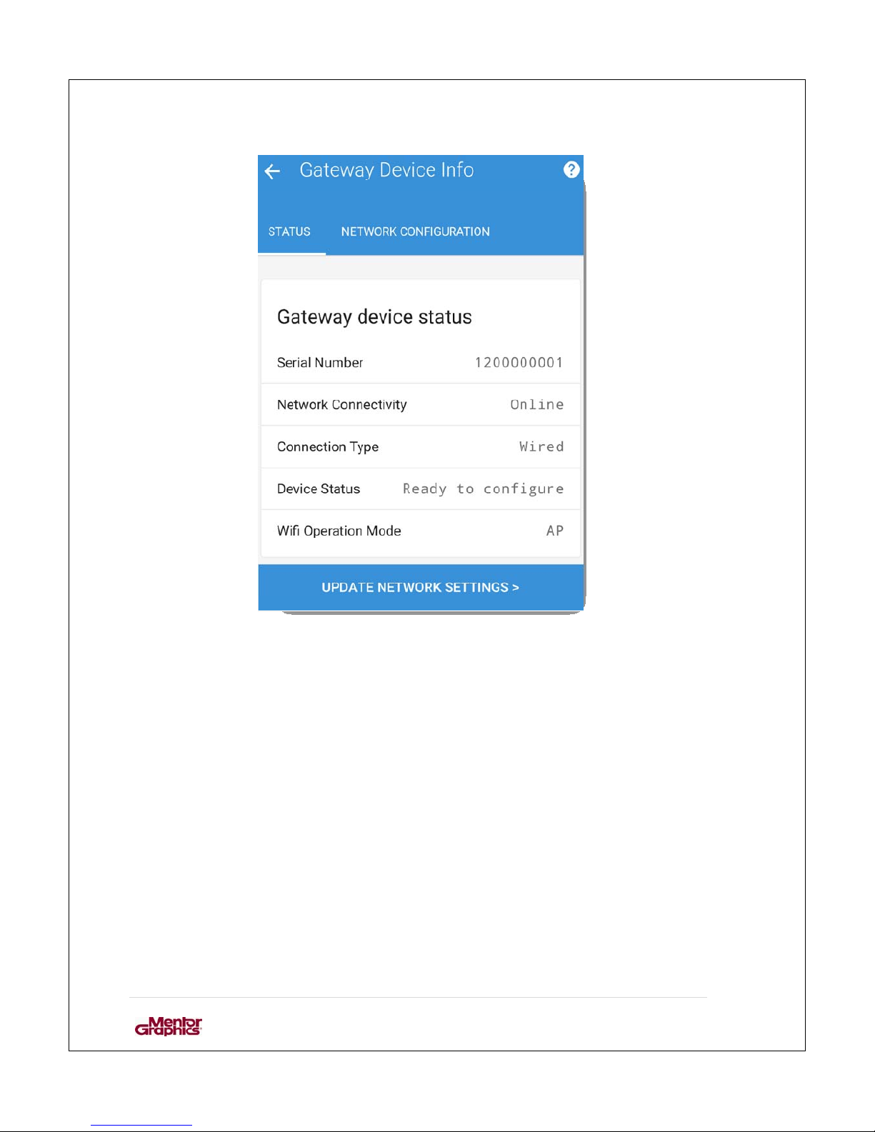
Updated configurations are displayed after reboot of CSP gateway device.
Page 29
User Manual for MF0200 Gateway Box
28 | Page
Figure 16: Updated network configuration
Page 30
User Manual for MF0200 Gateway Box
29 | Page
Figure 17: Updated Status
Page 31
User Manual for MF0200 Gateway Box
30 | Page
3.3.1.3.2. Ethernet - Static Configuration
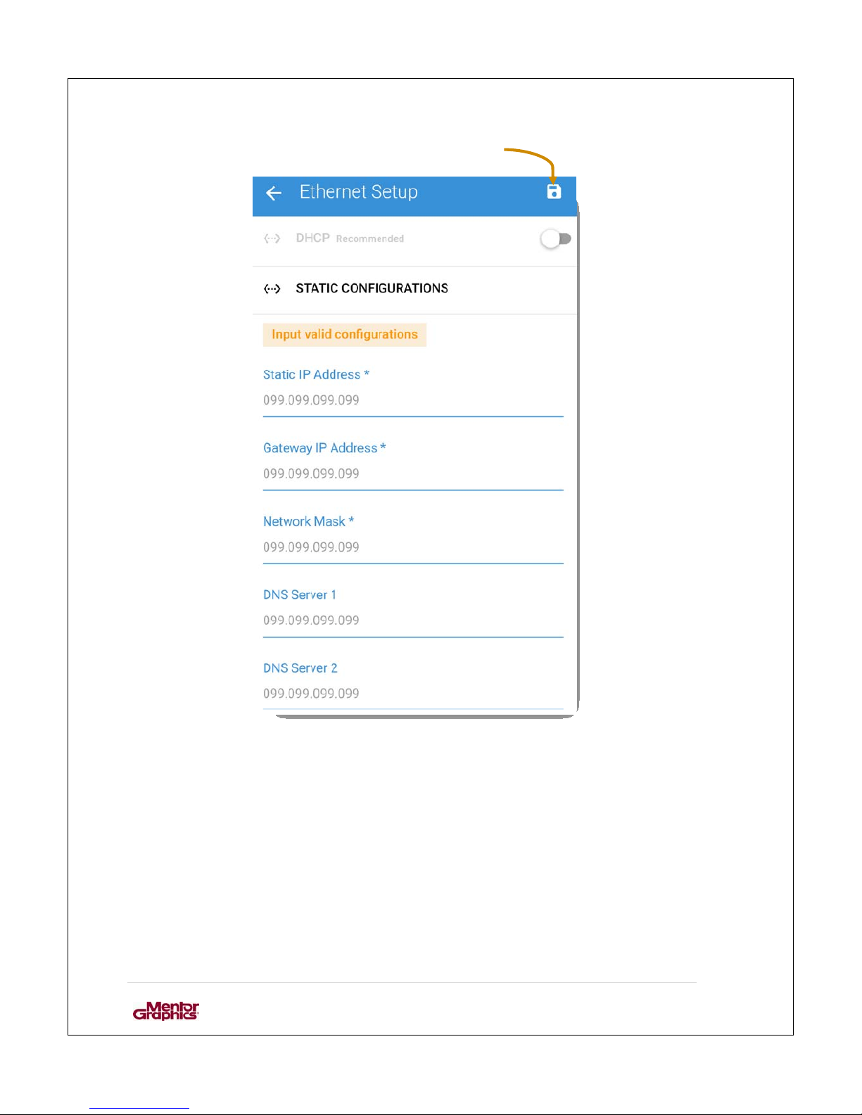
DHCP is selected by default but if the user requires to change it to Static configuration; it
can be changed by turning DHCP off .
Figure 18: Ethernet Setup
Page 32
User Manual for MF0200 Gateway Box
31 | Page
Fill in the needed fields and “click” save button.
Figure 19: Ethernet Setup- Static Configuration
The application prompts if the user wants to continue applying new settings to the
CSP gateway device. Same flow is followed as described in “Ethernet DHCP”.
Page 33
User Manual for MF0200 Gateway Box
32 | Page
3.3.1.4. Wireless Configuration
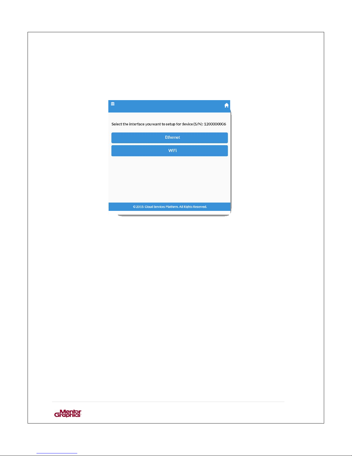
To configure the CSP gateway device to c o nnect to the CSP backend via wireles s
connection select Wi-Fi in the options and follow the following steps.
Figure 20: Configuration options
Page 34
User Manual for MF0200 Gateway Box
33 | Page
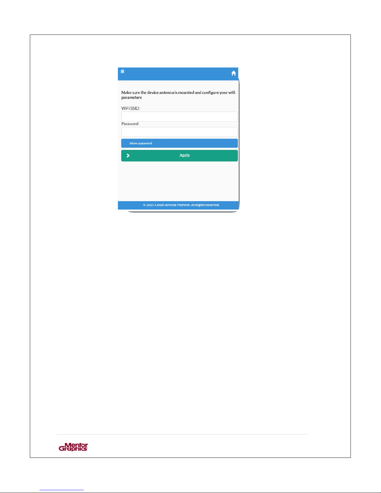
Figure 21: Wi-Fi credentials
Fill in the required fields:
1. Wi-Fi SSID: the SSID for the Wi-Fi network to be used.
2. Password: password for the Wi-Fi.
Page 35
User Manual for MF0200 Gateway Box
34 | Page
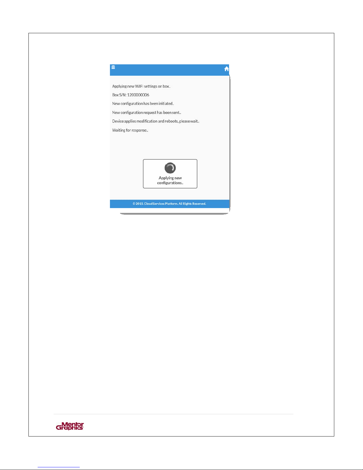
Figure 22: Applying configurations to the box\
Once the reboot of CSP gateway device is done it will be online via Wi-Fi.
Page 36
User Manual for MF0200 Gateway Box
35 | Page
3.3.2. S
CAN BARCODE
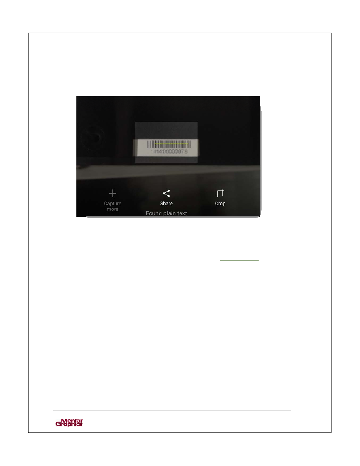
Alternatively, to add the gatewa y with barcode place the barcode in the vie w provided.
Figure 23: Barcode Scanning
After the device is recognized follow the same steps as given in Section 3.3.1.1
“Gateway
Device Info”; up till Section 3.3.2.
Page 37

User Manual for MF0200 Gateway Box
36 | Page
3.4. FIRMWARE UPDATE
When the CSP gateway device is properly configured it will automatically update the
firmware, if update is available. Operation of patch update can also be seen through
LED indication, as specified in Section no. 1.1.1. “CSP GATEWAY LED
INDICATOR CHART”.
Page 38
User Manual for MF0200 Gateway Box
37 | Page
4. ADD PERIPHERAL DEVICE
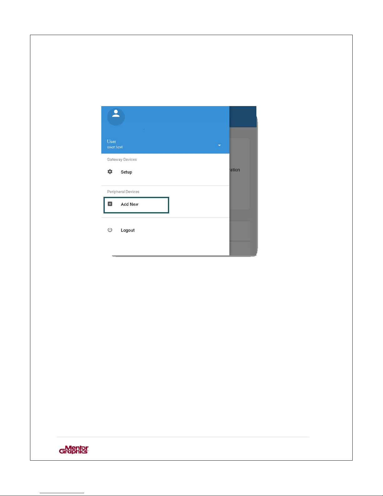
To add the peripheral de vic e g o t o the dashboard and select “Add New”.
Figure 24: Dashboard
Page 39
User Manual for MF0200 Gateway Box
38 | Page
4.1. STEP 1
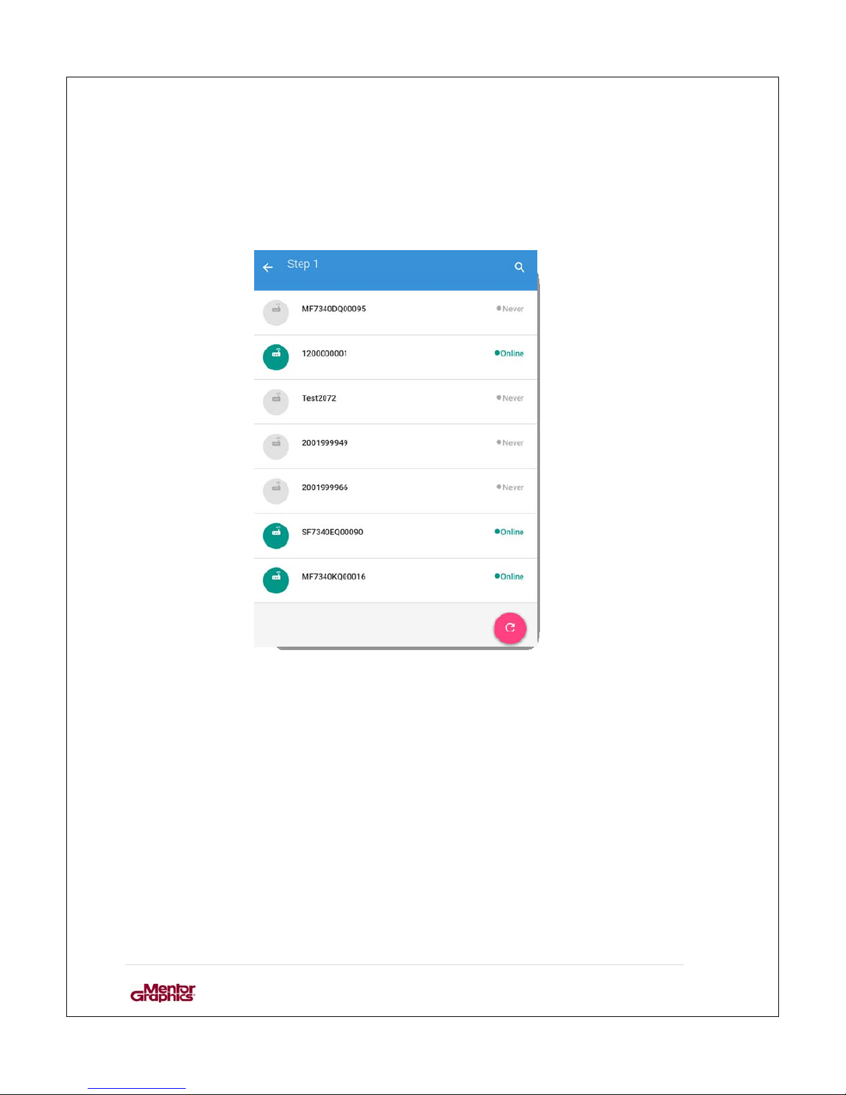
This will list the CSP gateway devices available for that particular account.
Figure 25: List of CSP gateway devices
Select the gateway device to add new peripheral.
Page 40
User Manual for MF0200 Gateway Box
39 | Page
4.2. STEP 2
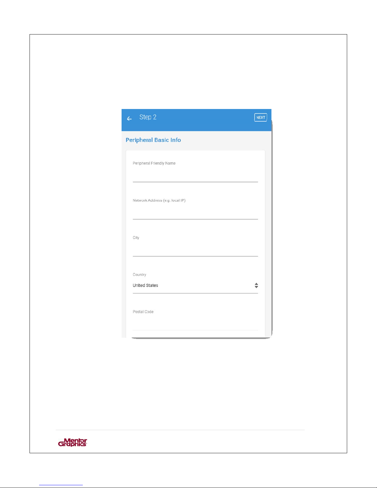
Input the basic information of the peripheral.
Figure 26: Peripheral Basic Info
Fill in the required fields:
1. Peripheral Friendly Name: name of the peripheral for easy recognition
2. Network Address: local IP of the periphe ral
3. City: name of the city
4. Country: name of the country
5. Postal code: postal code of the area
Click next when done with filling in the fields
Page 41
User Manual for MF0200 Gateway Box
40 | Page
4.3. STEP 3
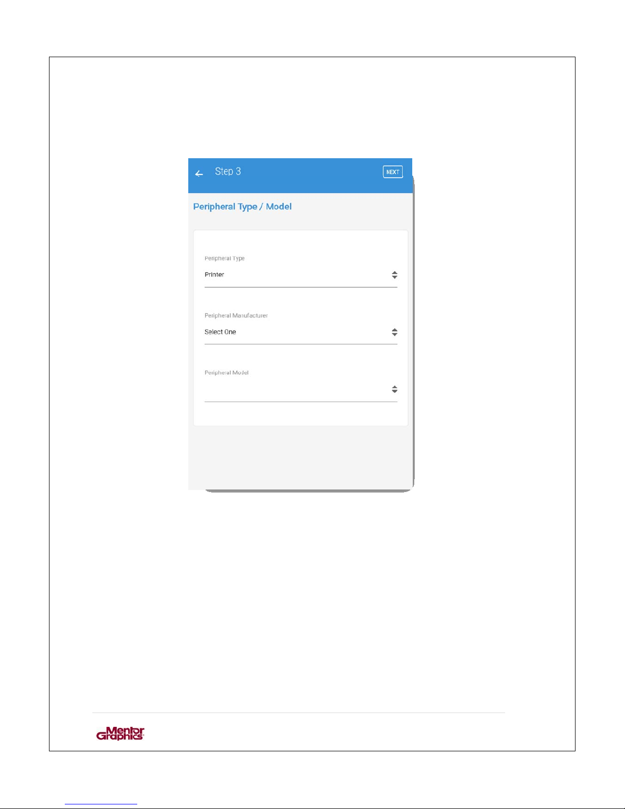
The information regarding m anufacturer, type and model of the pe ripheral are added in
this step.
Figure 27: Peripheral Type/ Model
Page 42
User Manual for MF0200 Gateway Box
41 | Page
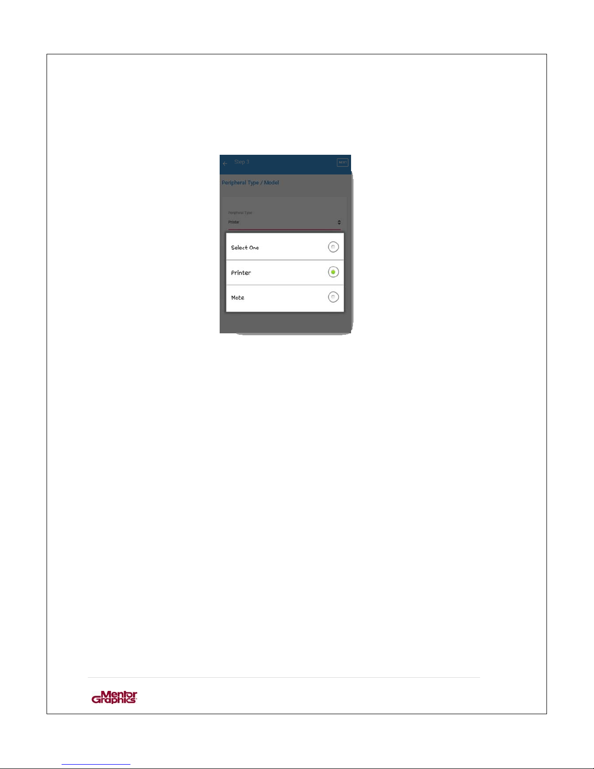
Select a peripheral type to add the type of the peripheral. There are two basic types of
peripherals printer and mote.
Figure 28: Types of peripheral
Page 43
User Manual for MF0200 Gateway Box
42 | Page
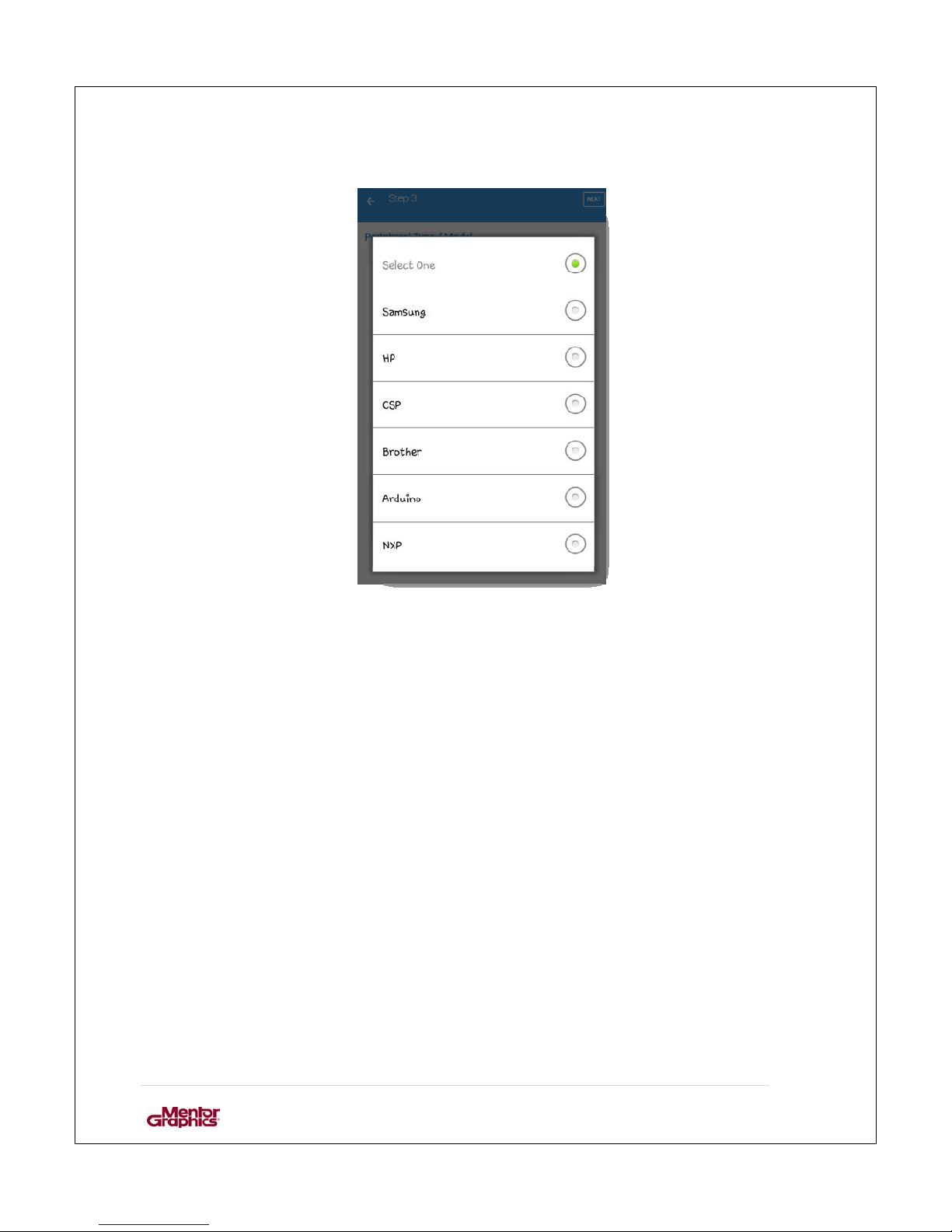
After choosing the peripheral type, select the manufacturer of the
peripheral.
Figure 29: Manufacturers
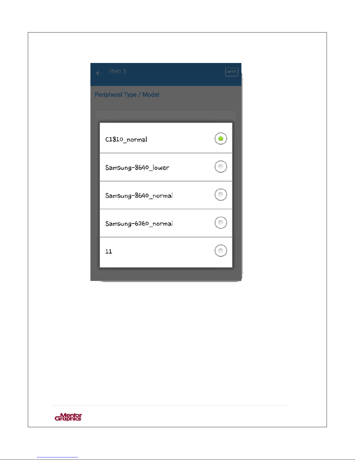
After choosing the manufacturer, select the model of the peripheral and click next.
Page 44
User Manual for MF0200 Gateway Box
43 | Page
Figure 30: models of peripherals
Page 45
User Manual for MF0200 Gateway Box
44 | Page
4.4. STEP 4
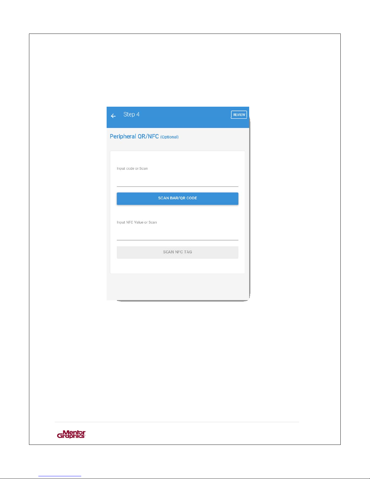
Add the QR and NFC details of the peripheral. It is an optional step. If the user does
not wish to input this information the syst em would generate these codes by it se lf.
Figure 31: Peripheral QR/NFC code
Both of these codes can be scanned or entered manually. Select review to see the
complete information regarding the peripheral.
Page 46
User Manual for MF0200 Gateway Box
45 | Page
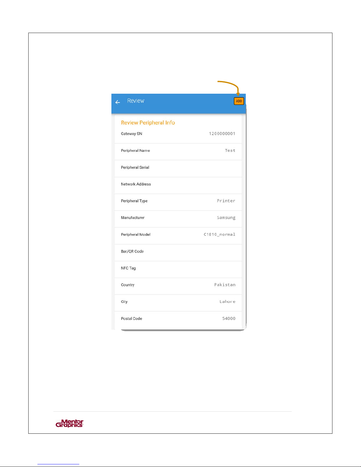
The final review of the periphe ral’s information. Tap the add butt o n t o a dd the
peripheral.
Figure 32: Review information
Page 47
User Manual for MF0200 Gateway Box
46 | Page
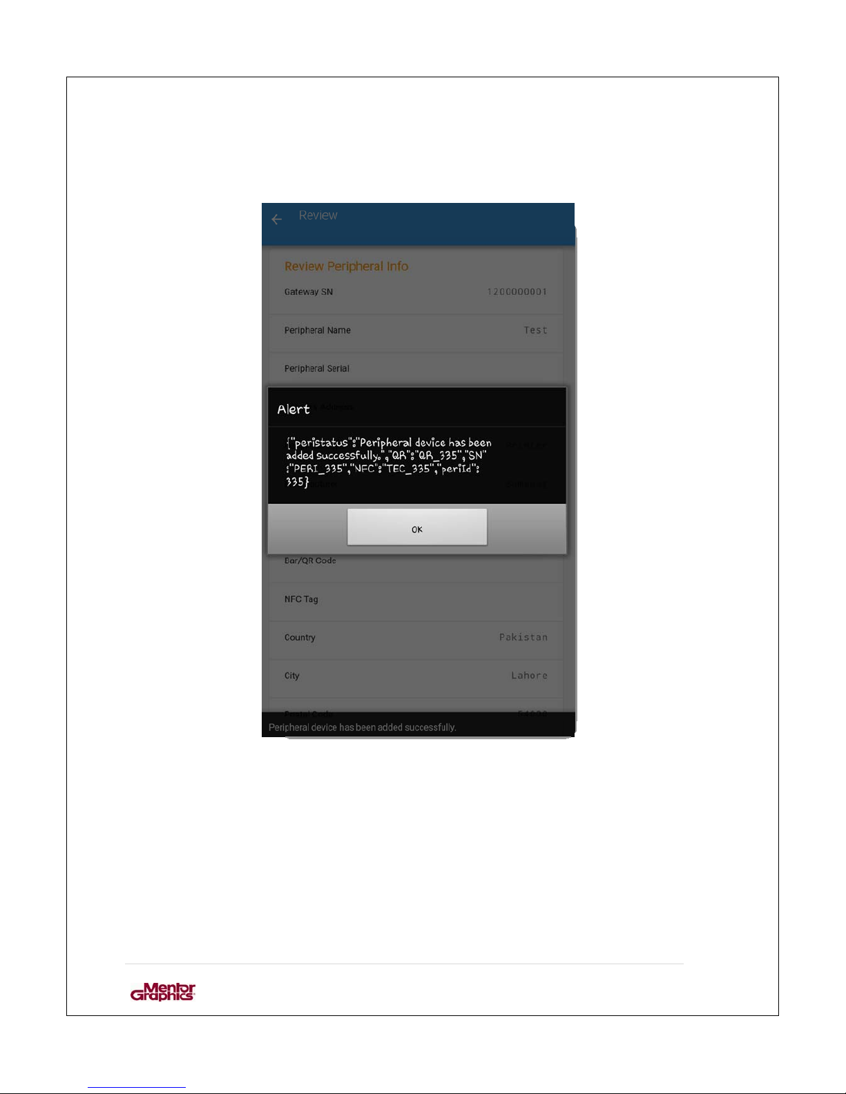
If the peripheral is added successfully following message is d is pla yed.
Figure 33: Success response
Page 48
User Manual for MF0200 Gateway Box
47 | Page
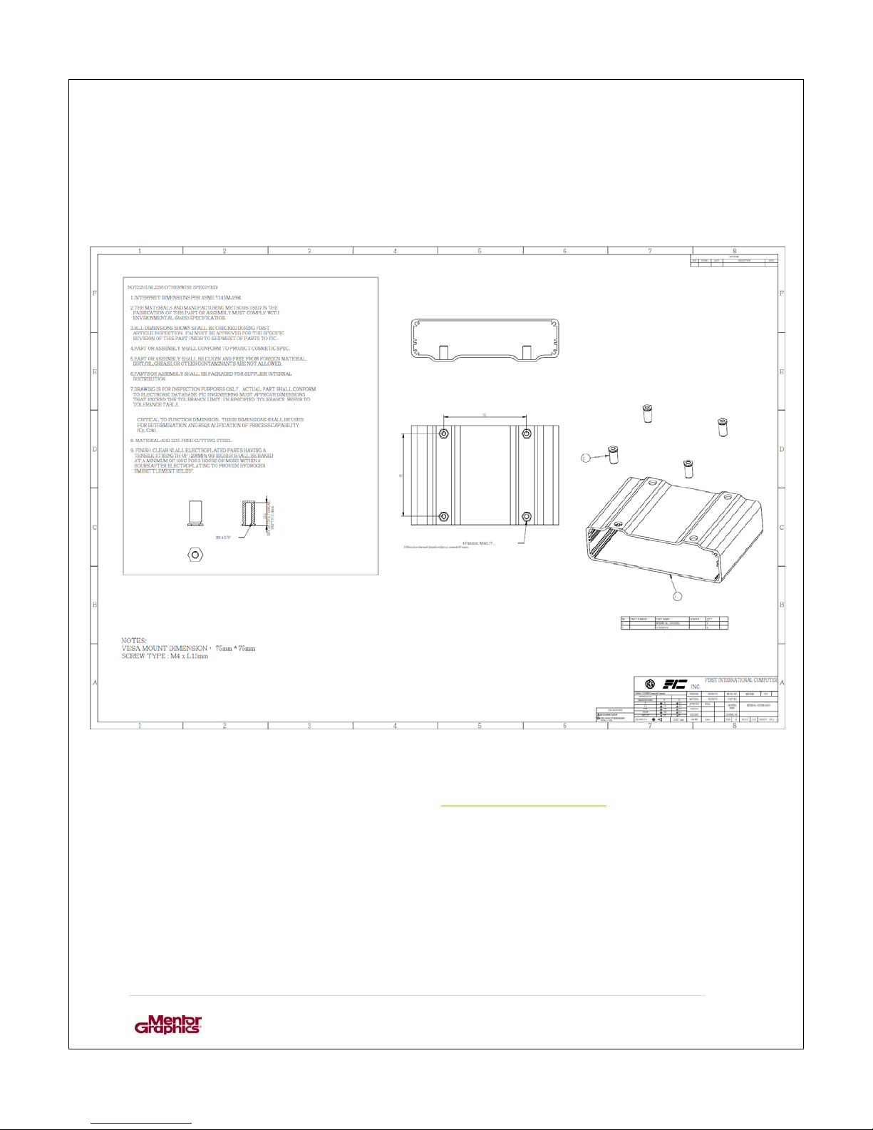
5. VESA MOUNT 75MM * 75MM INFORMATION
6. CONTACT US
If need be the user can contact for support at: [email protected]
 Loading...