

Page 1
Preliminary
Operating instructions
Betriebsanleitung
Temperature dry-well calibrator, model CTD4000
Temperatur-Blockkalibrator, Typ CTD4000
EN
DE
Temperature dry-well calibrator, model CTD4000
Page 2

ENDEOperating instructions model CTD4000 Page 3 - 34
Betriebsanleitung Typ CTD4000 Seite 35 - 66
Further languages can be found at www.wika.com.
© 05/2020 WIKA Alexander Wiegand SE & Co. KG
All rights reserved. / Alle Rechte vorbehalten.
®
WIKA
is a registered trademark in various countries.
®
WIKA
ist eine geschützte Marke in verschiedenen Ländern.
Prior to starting any work, read the operating instructions!
Keep for later use!
Vor Beginn aller Arbeiten Betriebsanleitung lesen!
Zum späteren Gebrauch aufbewahren!
2 WIKA operating instructions, model CTD4000
14366831.01 05/2020 EN/DE
Page 3

Contents
Contents
1. General information 3
2. Short overview 3
2.1 Overview . . . . . . . . . . . . . . . . . . . . . . . . . . . . . . . 3
2.2 Description. . . . . . . . . . . . . . . . . . . . . . . . . . . . . . . 3
3. Safety 4
3.1 Explanation of symbols . . . . . . . . . . . . . . . . . . . . . . . . . . 4
3.2 Intended use . . . . . . . . . . . . . . . . . . . . . . . . . . . . . . 4
3.3 Scope of delivery . . . . . . . . . . . . . . . . . . . . . . . . . . . . 4
3.4 Improper use . . . . . . . . . . . . . . . . . . . . . . . . . . . . . . 5
3.5 Personnel qualification. . . . . . . . . . . . . . . . . . . . . . . . . . . 6
3.6 Personal protective equipment . . . . . . . . . . . . . . . . . . . . . . . . 6
3.7 Labelling, safety marks . . . . . . . . . . . . . . . . . . . . . . . . . . 6
4. Design and function 7
4.1 Overview of the different instrument models . . . . . . . . . . . . . . . . . . . 7
4.2 Isometric views . . . . . . . . . . . . . . . . . . . . . . . . . . . . . 7
4.3 Description of the temperature controller . . . . . . . . . . . . . . . . . . . . 8
4.4 Voltage supply . . . . . . . . . . . . . . . . . . . . . . . . . . . . . 9
4.5 Fuse . . . . . . . . . . . . . . . . . . . . . . . . . . . . . . . . . 9
4.6 Heating resistance (CTD4000-375 or CTD4000-650) . . . . . . . . . . . . . . . . 10
4.7 Temperature sensors . . . . . . . . . . . . . . . . . . . . . . . . . . . 10
4.8 Safety thermostat (CTD4000-375 or CTD4000-650). . . . . . . . . . . . . . . . . 10
4.9 Fan . . . . . . . . . . . . . . . . . . . . . . . . . . . . . . . . . 10
4.10 Inserts . . . . . . . . . . . . . . . . . . . . . . . . . . . . . . . . 10
5. Transport, packaging and storage 11
5.1 Transport . . . . . . . . . . . . . . . . . . . . . . . . . . . . . . . 11
5.2 Packaging and storage . . . . . . . . . . . . . . . . . . . . . . . . . . 11
6. Commissioning, operation 11
6.1 Voltage supply . . . . . . . . . . . . . . . . . . . . . . . . . . . . . 11
6.2 Use at high temperatures . . . . . . . . . . . . . . . . . . . . . . . . . . 11
6.3 First commissioning. . . . . . . . . . . . . . . . . . . . . . . . . . . . 12
6.4 Operating position . . . . . . . . . . . . . . . . . . . . . . . . . . . . 12
6.5 Switching on the calibrator . . . . . . . . . . . . . . . . . . . . . . . . . 12
6.6 Setting a set temperature . . . . . . . . . . . . . . . . . . . . . . . . . . 12
6.7 Testing or calibrating temperature probes . . . . . . . . . . . . . . . . . . . . 12
6.7.1 Testing of temperature probes . . . . . . . . . . . . . . . . . . . . . . . . . . . . . . . . . . . . . 12
6.7.2 Calibrating temperature probes. . . . . . . . . . . . . . . . . . . . . . . . . . . . . . . . . . . . .12
6.7.3 Positioning the temperature probe . . . . . . . . . . . . . . . . . . . . . . . . . . . . . . . . . . . 12
6.7.4 Calibration with one reference . . . . . . . . . . . . . . . . . . . . . . . . . . . . . . . . . . . . . 13
6.7.5 After the test or the calibration . . . . . . . . . . . . . . . . . . . . . . . . . . . . . . . . . . . . . 14
6.8 Switch test function . . . . . . . . . . . . . . . . . . . . . . . . . . . . 14
6.9 Cooling down the metal block . . . . . . . . . . . . . . . . . . . . . . . . 15
7. Operating the calibrator 16
7.1 Setting a temporary set temperature (set-point mode) . . . . . . . . . . . . . . . . 16
7.2 Programming (main menu) . . . . . . . . . . . . . . . . . . . . . . . . . 16
7.3 Short description of the menu . . . . . . . . . . . . . . . . . . . . . . . . 16
7.3.1 Menu structure, parameter levels. . . . . . . . . . . . . . . . . . . . . . . . . . . . . . . . . . . . 17
7.3.2 First menu level - General settings . . . . . . . . . . . . . . . . . . . . . . . . . . . . . . . . . . . 18
EN
14366831.01 05/2020 EN/DE
1WIKA operating instructions, model CTD4000
Page 4

Contents
7.3.3 Second menu level - Settings for optimising the control . . . . . . . . . . . . . . . . . . . . . . . 19
7.3.4 Third menu level - Recalibration of the instrument . . . . . . . . . . . . . . . . . . . . . . . . . . 20
7.3.5 Fourth menu level - Settings of the temperature controller . . . . . . . . . . . . . . . . . . . . . . 21
8. Serial communication 22
8.1 List of the variables and parameters . . . . . . . . . . . . . . . . . . . . . . 22
8.2 Data reading . . . . . . . . . . . . . . . . . . . . . . . . . . . . . . 23
EN
8.3 Data writing (FLOAT VARIABLES) . . . . . . . . . . . . . . . . . . . . . . . 23
9. Faults 24
10. Maintenance, cleaning and recalibration 25
10.1 Maintenance . . . . . . . . . . . . . . . . . . . . . . . . . . . . . . 25
10.2 Cleaning . . . . . . . . . . . . . . . . . . . . . . . . . . . . . . . 25
10.3 Recalibration . . . . . . . . . . . . . . . . . . . . . . . . . . . . . . 25
10.3.1 Calibration of the internal probe by the user . . . . . . . . . . . . . . . . . . . . . . . . . . . . . . 26
11. Dismounting, return and disposal 27
11.1 Dismounting . . . . . . . . . . . . . . . . . . . . . . . . . . . . . . 27
11.2 Return . . . . . . . . . . . . . . . . . . . . . . . . . . . . . . . . 27
11.3 Disposal . . . . . . . . . . . . . . . . . . . . . . . . . . . . . . . 27
12. Specifications 28
13. Accessories 30
Declarations of conformity can be found online at www.wika.com.
2 WIKA operating instructions, model CTD4000
14366831.01 05/2020 EN/DE
Page 5

1. General information / 2. Short overview
1. General information
■
The model CTD4000 temperature dry-well calibrator
described in the operating instructions has been designed
and manufactured using state-of-the-art technology.
All components are subject to stringent quality and
environmental criteria during production. Our management
systems are certified to ISO 9001 and ISO 14001.
■
These operating instructions contain important information
on handling the instrument. Working safely requires that all
safety instructions and work instructions are observed.
■
Observe the relevant local accident prevention regulations
and general safety regulations for the instrument's range
of use.
■
The operating instructions are part of the product and
must be kept in the immediate vicinity of the instrument
and readily accessible to skilled personnel at any time.
Pass the operating instructions on to the next operator or
owner of the instrument.
■
Skilled personnel must have carefully read and
understood the operating instructions prior to beginning
any work.
■
The general terms and conditions contained in the sales
documentation shall apply.
■
Subject to technical modifications.
■
Factory calibrations / DKD/DAkkS calibrations are carried
out in accordance with international standards.
■
Further information:
- Internet address: www.wika.de / www.wika.com
- Relevant data sheet: CT 41.10
- Application consultant: Tel.: +49 9372 132-0
Fax: +49 9372 132-406
info@wika.de
EN
2. Short overview
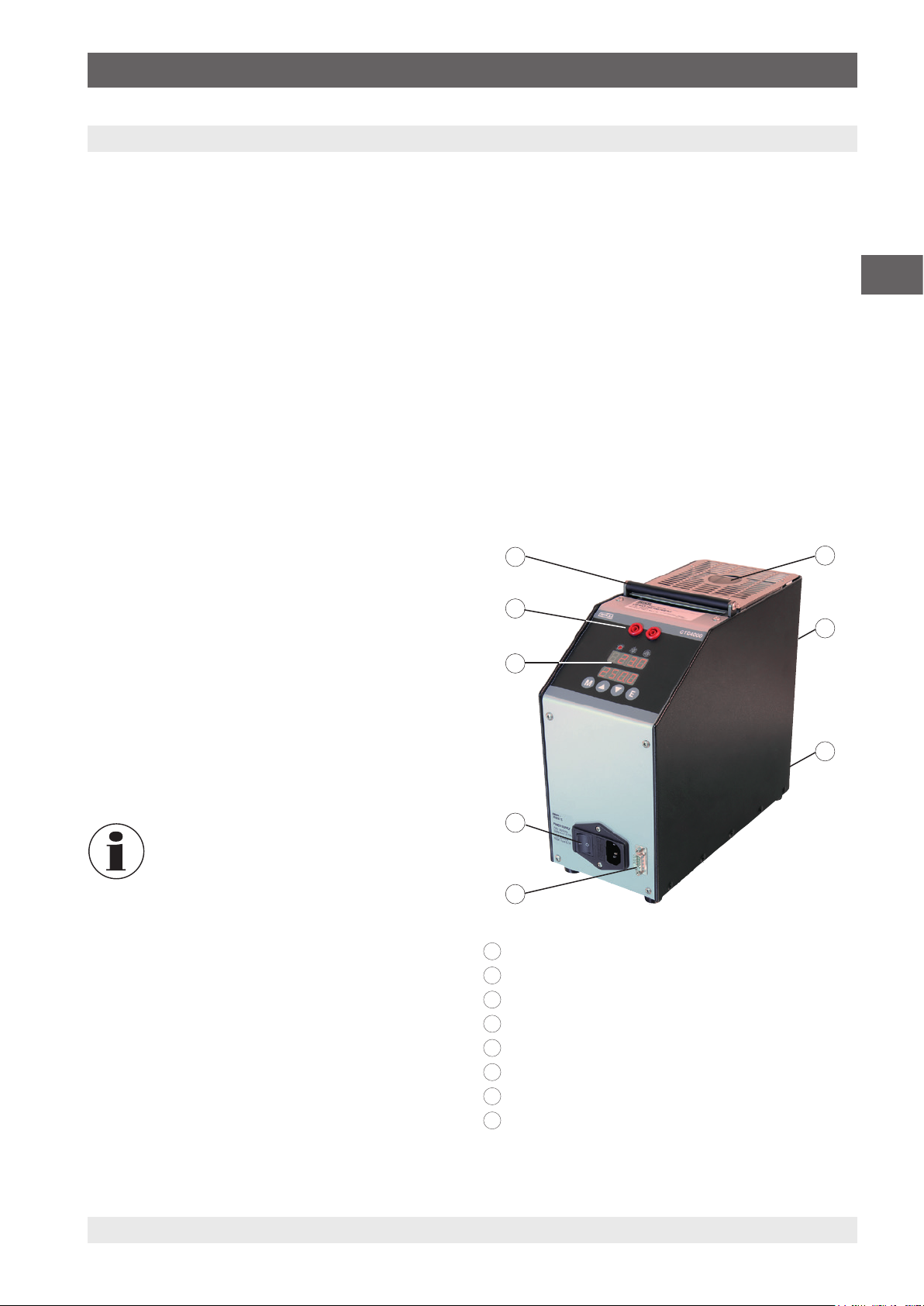
2.1 Overview
8
7
6
5
1
Temperature block
2
1
2
User interface
3
RS-232 interface
4
Power connection
5
Main switch
6
Fuse holder
7
Connections for temperature switch test
8
Carrying handle
2.2 Description
The calibrator has been designed for on-site applications
as well as for the harsh conditions of the naval and marine
3
sectors.
The thermal part of the calibrator is made of a metal block
heated/cooled with resistors or with Peltier thermoelectric
modules. In the metal block there is one bore in which the
interchangeable insert is placed.
14366831.01 05/2020 EN/DE
4
3WIKA operating instructions, model CTD4000
Page 6
2. Short overview / 3. Safety
2.3 Scope of delivery
For model CTD4000-140 temperature dry-well calibrator
■
Calibrator
■
Power cord, 1.5 m [5 ft] with safety plug
■
Replacement tool
■
Operating instructions
■
Drilled insert with 4 bores: 3.3 mm, 4.8 mm and
EN
2 x 6.4 mm [0.13 in, 0.19 in and 2 x 0.25 in]
For model CTD4000-375 temperature dry-well calibrator
■
Calibrator
■
Power cord, 1.5 m [5 ft] with safety plug
■
Replacement tool
■
Operating instructions
■
Drilled insert with 4 bores: 3.2 mm, 4.8 mm, 6.4 mm and
11.1 mm [0.13 in, 0.19 in, 0.25 in and 0.44 in]
3. Safety
For model CTD4000-650 temperature dry-well calibrator
■
Calibrator
■
Power cord, 1.5 m [5 ft] with safety plug
■
Replacement tool
■
Operating instructions
■
Drilled insert with 4 bores: 3.2 mm, 5 mm, 7 mm and
10.5 mm [0.13 in, 0.2 in, 0.28 in and 0.41 in]
Cross-check scope of delivery with delivery note.
3.1 Explanation of symbols
WARNING!
... indicates a potentially dangerous situation
that can result in serious injury or death, if not
avoided.
CAUTION!
... indicates a potentially dangerous situation that
can result in light injuries or damage to property
or the environment, if not avoided.
DANGER!
... identifies hazards caused by electric power.
Should the safety instructions not be observed,
there is a risk of serious or fatal injury.
WARNING!
... indicates a potentially dangerous situation that
can result in burns, caused by hot surfaces or
liquids, if not avoided.
Information
... points out useful tips, recommendations
and information for efficient and trouble-free
operation.
3.2 Intended use
The model CTD4000 portable temperature dry-well calibrator
is a portable unit that has been designed for on-site
applications as well as for the harsh conditions of the naval
and marine sectors.
The temperature dry-well calibrator is intended for the
calibration of thermometers, temperature switched/
thermostats, resistance thermometers and thermocouples.
The operational safety of the delivered instruments is only
assured if the equipment is employed for its intended use
(verification of temperature sensors). The given limit values
should never be exceeded (see chapter 12 “Specifications”).
Maximum ambient conditions at place of use:
■
Ambient temperature: 5 ... 45 °C [41 ... 113 °F]
■
Humidity: 95 % relative humidity (non-condensing)
This instrument is not permitted to be used in hazardous
areas!
Notes for instruments with EMC and class A
This is class A equipment for emissions and is intended
for use in industrial environments. In other environments,
e.g. residential or commercial installations, it can interfere
with other equipment under certain conditions. In such
circumstances the operator is expected to take the
appropriate measures.
4 WIKA operating instructions, model CTD4000
14366831.01 05/2020 EN/DE
Page 7
3. Safety
The instrument has been designed and built solely for
the intended use described here, and may only be used
accordingly.
The technical specifications contained in these operating
instructions must be observed. Improper handling or
operation of the instrument outside of its technical
specifications requires the instrument to be taken out of
service immediately and inspected by an authorised WIKA
service engineer.
Handle electronic precision measuring instruments with
the required care (protect from humidity, impacts, strong
magnetic fields, static electricity and extreme temperatures,
do not insert any objects into the instrument or its openings).
Plugs and sockets must be protected from contamination.
The manufacturer shall not be liable for claims of any type
based on operation contrary to the intended use.
3.3 Improper use
WARNING!
Injuries through improper use
Improper use of the instrument can lead to
hazardous situations and injuries or damage to
property.
▶
Refrain from unauthorised modifications to
the instrument.
▶
Do not use the instrument within hazardous
areas.
▶
Do not use the instrument with abrasive or
viscous media.
▶
Only ever use the power cord supplied.
▶
Observe the operating parameters in
accordance with chapter 12 “Specifications”.
To avoid injuries or damage to property observe further
points:
■
Keep clear the area around the calibrator on all sides and
especially behind the calibrator.
■
Do not put anything on the top of the calibrator.
■
Only carry out maintenance on the calibrator when it has
cooled down and been switched off.
■
Before switching off, ensure that the calibrator has
cooled to room temperature (CTD4000-140) or < 100 °C
(CTD4000-375/CTD4000-650).
■
The calibrator must only be stored in the carrying case
once it has cooled down.
■
Do not switch off the calibrator when it is operating at high
temperature because the protective grille and the case
may overheat.
■
Do not use any oil or liquids since these can lead to
damage of the calibrator.
■
Do not put any fuel containers near the calibrator.
Voltage supply
■
The mains socket must be freely accessible at all times!
■
Ensure that the female connector, when connected to the
voltage supply, is properly grounded.
■
With the following points, the temperature dry-well
calibrator must be disconnected by unplugging the power
cord from the mains socket.
▶
Before exchanging the fuse
▶
Before cleaning
▶
Before service/maintenance
▶
In the event of danger
Interface
Do not connect any voltage to the RS-232 input.
Fuse
Remove the fuse from the calibrator only when the power
connection has been disconnected from the mains.
Temperature switch test
■
Do not connect any voltage to the switch test connection.
■
Do not connect any voltage during the test of the
thermostats.
EN
Temperature dry-well calibrator
■
Only operate the calibrator in a defect-free, functioning
condition.
■
Faultless and safe operation of this calibrator requires
proper transport, professional storage, installation,
mounting and use as intended in addition to careful
operation and maintenance.
■
The calibrator has been designed as a controller. With
any operation of the calibrator not expressly provided
for in these operating instructions, additional protective
measures must be taken.
■
The electronic µ processor is factory configured so that all
technical specifications are maintained. These parameters
must not be changed, above all to prevent malfunction or
failure which could lead to damage.
14366831.01 05/2020 EN/DE
Any use beyond or different to the intended use is considered
as improper use.
Do not use this instrument in safety or emergency stop
devices.
5WIKA operating instructions, model CTD4000
Page 8
3. Safety
3.4 Personnel qualification
WARNING!
Risk of injury should qualification be
insufficient!
Improper handling can result in considerable
injury and damage to property.
▶
The activities described in these operating
EN
instructions may only be carried out by
skilled personnel who have the qualifications
described below.
Skilled personnel
Skilled personnel, authorised by the operator, are understood
to be personnel who, based on their technical training,
knowledge of measurement and control technology and
on their experience and knowledge of country-specific
regulations, current standards and directives, are capable
of carrying out the work described and independently
recognising potential hazards.
Special operating conditions require further appropriate
knowledge, e.g. of aggressive media.
3.5 Personal protective equipment
The personal protective equipment is designed to protect the
skilled personnel from hazards that could impair their safety
or health during work. When carrying out the various tasks
on and with the instrument, the skilled personnel must wear
personal protective equipment.
Follow the instructions displayed in the work area
regarding personal protective equipment!
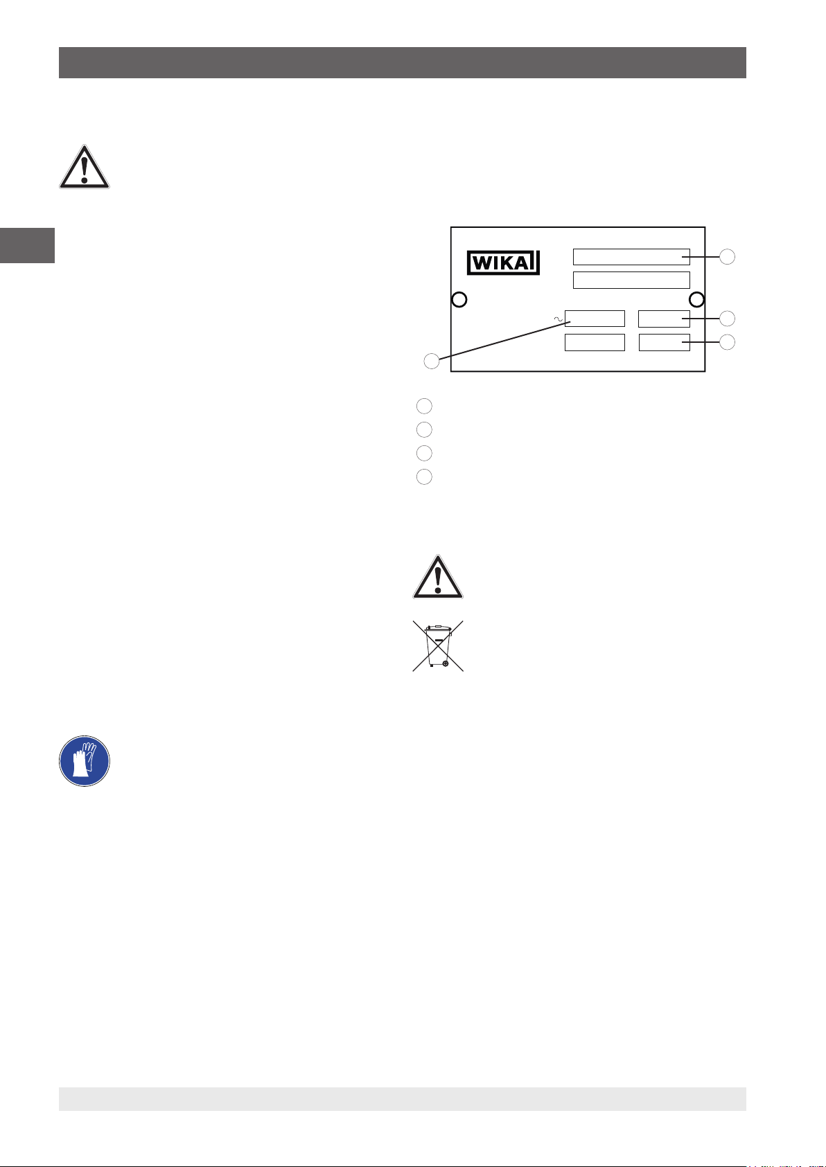
3.6 Labelling, safety marks
The operator is obliged to maintain the product label in a
legible condition.
Product label (example)
The product label is fixed on the rear of the instrument.
Mod.
Matr.
WIKA Alexander W iegand
SE & Co. KG
Alexander-Wiegand Str.30
63911 Klingenberg
Germany
www.wika.de
4
1
Model designation
2
Frequency in Hz
3
Power in W
4
Operating voltage
V
bar
Hz
W
Explanation of symbols
Before mounting and commissioning the
instrument, ensure you read the operating
instructions!
Do not dispose of with household waste. Ensure
a proper disposal in accordance with national
regulations.
1
2
3
The requisite personal protective equipment must be
provided by the operating company.
Wear protective gloves!
Protect hands from contact with hot surfaces and
aggressive media.
14366831.01 05/2020 EN/DE
6 WIKA operating instructions, model CTD4000
Page 9
4. Design and function
4. Design and function
4.1 Overview of the different instrument models
■
CTD4000-140 (cooling and heating)
■
CTD4000-375 (heating)
■
CTD4000-650 (heating)
The temperature dry-well calibrator consists of a robust,
grey-painted steel case, with a carrying handle on top.
The rear part of the case contains a metal block with a
19 x 150 mm or 26 x 150 mm bore in which the inserts can
be placed.
With the help of the inserts temperature probes of different
sizes can then be calibrated.
The heater element heats the block and an electronic µ
controller with static relay output checks and regulates the
temperature.
The metal block is thermally insulated.
A centrally mounted fan generates a constant air flow that
reduces the temperature of the case.
The air flow is divided in two parts: One part of the air flows
from the back of the calibrator, while the second part of the
flow is parallel to the top grid of the calibrator. Thus, the
stem of the sensor is above the insert at the lowest possible
temperature.
The front part of the case contains the complete electronic
unit for controlling the reference temperature.
To control the heating elements, solid-state relays (SSRs) are
used.
On the front panel is the controller, which is fitted with an LED
display (2-line) for the reference and set temperature.
4.2 Isometric views
Front and top
On the top of the temperature dry-well calibrator, you will find
the dry well access opening for inserting the insert.
The controller, with display and controls, is located on the
front of the calibrator.
The temperature switch test is found through the indicator.
In the lower area are the mains connector socket and the
power switch with its fuse holder.
Furthermore, the mains voltage and the fuse rating is given.
On the right hand side, next to the power connection is
located the RS-232 interface.
Rear of the instrument
On the rear of the case are located the product label and the
fan.
This must not be obstructed in any way!
8
7
6
1
2
3
EN
The calibrator is fitted with the following
protective devices to prevent hazards in
operation.
14366831.01 05/2020 EN/DE
■
Temperature controller that recognises any
possible break in the temperature sensor and
disconnects the heating
■
Maximum temperature safety thermostat to
disconnect the heating system
■
Protective grille to prevent any contact with
the metal block
■
Protective fuses
5
4
1
Temperature block with insert
2
Fan
3
Product label
4
RS-232 interface
5
Mains connector socket with power switch and fuse
6
Temperature controller
7
Temperature switch test
8
Carrying handle, retractable
7WIKA operating instructions, model CTD4000
Page 10
4. Design and function
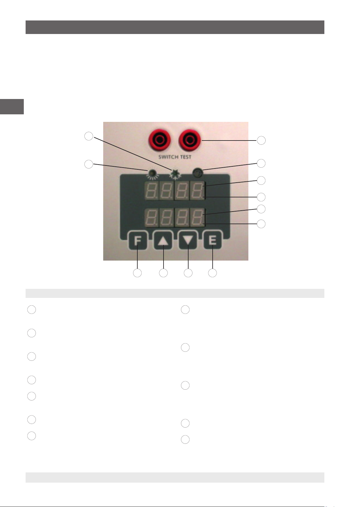
4.3 Description of the temperature controller
The temperature controller is a PID microprocessor, which
can be set from -30 ... 140 °C, 0 ... 375 °C and 0 ... 650 °C
[-22 ... 284 °F, 32 ... 707 °F or 32 ... 1,202 °F]. The display
indicates the current temperature and the set point.
EN
Controls
12
11
89 710
Overview of the operating elements of the temperature controller
Connections for temperature switch test
1
8
For further information, see chapter 6.8 “Switch test
function”.
Switch test LED
2
Lights up when the temperature switch contact is
closed.
Display 1
3
9
Displays the value of the actual temperature or the
value of the function selected.
Stability LED
4
When the LED is flashing, the temperature is stable.
Display 2
5
10
Set temperature display
The parameters are displayed in the function menu.
Switch test
6
When the LED is flashing, the function is active.
Button [E]
7
Confirms the selected values or the selected function.
11
12
1
2
3
4
5
6
Button [▼]
Lowers the value which is shown on display 1 or
display 2.
By holding the [▼] button down, the speed is
increased.
Button [▲]
Increases the value which is shown on display 1 or
display 2.
By holding the [▲] button down, the speed is
increased.
Function menu button [F]
By pressing both the [F] and [▲] buttons at the same
time, the 2nd level menu is accessed.
With the [F] button, the function is called up and can
be browsed in the menu level.
Heating LED
Lights up when the calibrator is heating.
Cooling LED
Lights up when the calibrator is cooling.
8 WIKA operating instructions, model CTD4000
14366831.01 05/2020 EN/DE
Page 11
4. Design and function
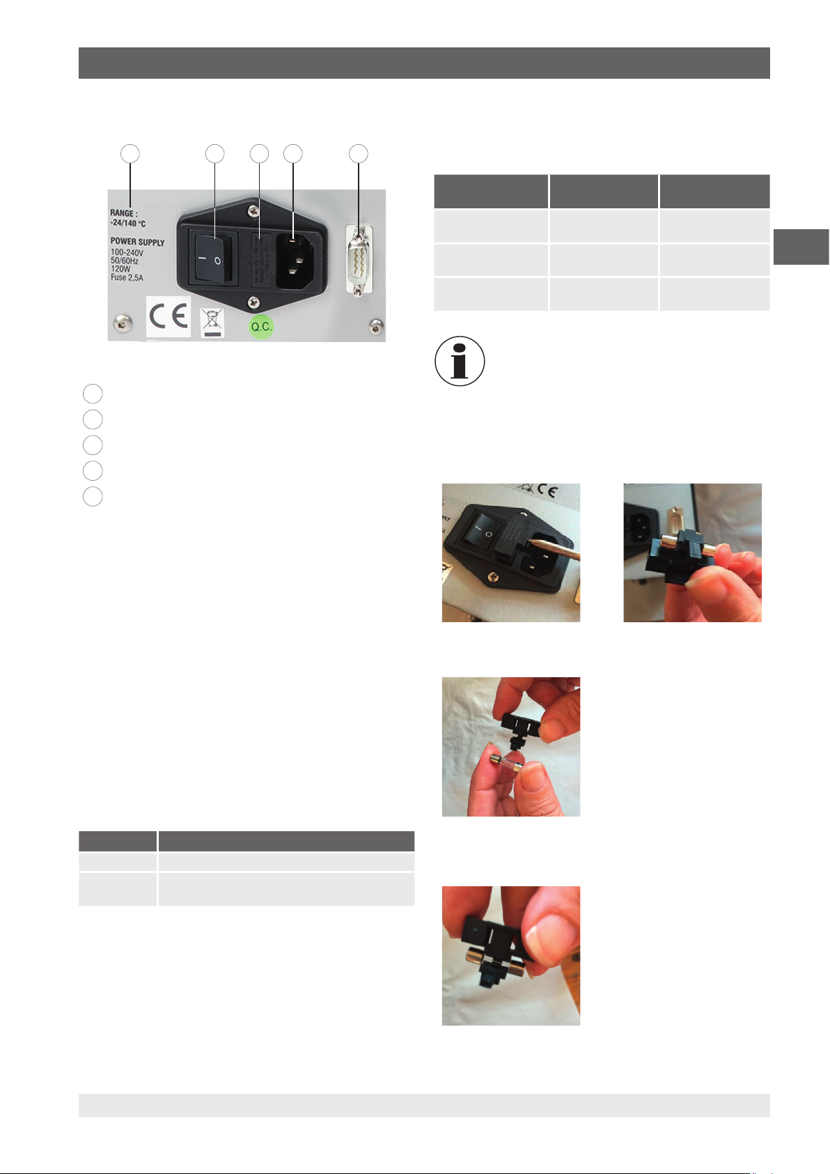
4.4 Voltage supply
13 14 15 16 17
Information about the calibrator
13
Main switch
14
Fuse
15
Power connection
16
RS-232 interface
17
For further information, see chapter 8 “Serial
communication”.
4.5 Fuse
The calibrators are fitted with the following fuses, in
accordance with the table:
Operating
voltage
AC 100 ... 240 V 2.5 A slow blow
AC 100/115 V - 6.3 A slow blow
AC 230 V - 3.15 A slow blow
Only use type F 5 x 20 mm fuses. All the
electrical components are found below the main
switch.
Changing of the fuse
1. Open the fuse container, using a screwdriver for example,
and pull it out.
CTD4000-140 CTD4000-375
CTD4000-650
-
fuse
fuse
fuse
EN
Voltage supply for CTD4000-140
The CTD4000-140 calibrator operates with an operating
voltage of AC 100 ... 240 V, 50/60 Hz.
Voltage supply for CTD4000-375 and CTD4000-650
The calibrator runs on a voltage of AC 230 V or AC 115 V,
50/60 Hz.
The calibrator automatically sets the supply voltage to a
voltage of AC 115 V or AC 230 V.
The instruments can be supplied with voltage of AC 115 V or
AC 230 V (50/60 Hz).
The fuse must be changed, if the supply voltage changes
from AC 230 V to AC 115 V.
Voltage Fuse
AC 230 V 3.15 A (factory delivery)
AC 115 V 6.3 A (included in standard scope of delivery, in
a bag)
For both calibrators, in total 4 fuses are included in the
standard scope of delivery. One is already built-in; the
remaining are placed in labelled plastic bags.
⇒
2. Remove the fuse from the clamp.
3. Place new fuse into the clamp.
14366831.01 05/2020 EN/DE
9WIKA operating instructions, model CTD4000
Page 12
4. Design and function
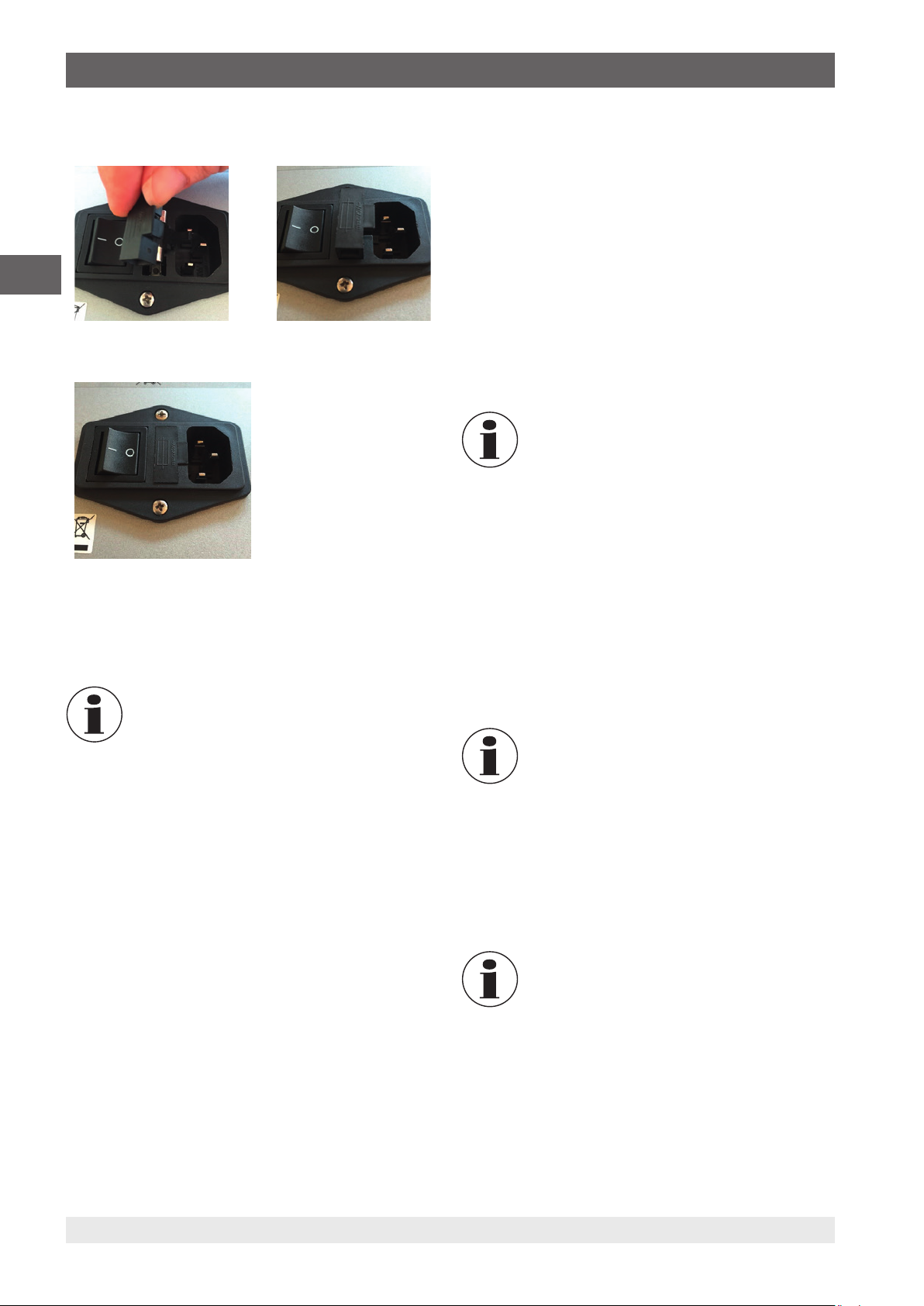
4. Insert the clamp into the fuse container.
⇒
EN
5. Press in the fuse container fully.
4.6 Heating resistance (CTD4000-375 or CTD4000-650)
The resistance is made from stainless steel; the max power
is 630 W and it can become very hot.
The use of the calibrator at continuous high
temperatures reduces the service life of the
resistor. Limit the number of hours at which the
resistance is used at maximum temperatures
to the time required by the calibrator in order to
prolong the life of the resistance.
4.8 Safety thermostat (CTD4000-375 or CTD4000-650)
The calibrator is fitted with a thermal fuse for the highest
temperature, which has a manual reset button. The thermal
fuse switches off the heating system as soon as there is an
error.
If Ht is showing on the display means, that the temperature
has exceeded the upper limit.
If Ht is on the display:
1. Cool the temperature calibrator
The temperature must fall to at least 60 ... 80 °C
⇒
[140 ... 176 °F] under the high set value (standard).
2. Switch off the calibrator then switch on again a few
second later.
The thermostat has been factory set to 660 °C
±10 °C [1,220 °F ±10 °F] with the CTD4000-650
and to 385 °C ±10 °C [725 °F ±10 °F] with the
CTD4000-375.
If the problem persists, disconnect the calibrator from the
voltage supply and rectify the possible fault.
4.9 Fan
A fan is installed in the calibrator. The fan works with two
different speeds: the control system switches on the fan
at minimum speed with increasing temperature, and at
maximum speed for decreasing the temperature. The fan
keeps the case of the calibrator at a low temperature when
the temperature increases and assist the cooling process.
Every hole at the bottom and at the back of
CTD4000 must be kept free in order to let the air
flow properly.
The equalising block has an opening of 26 mm into which
the inserts for almost any temperature probe size can be
inserted. The function of this block is to make the temperature
in the calibration zone uniform.
The bores are dependent on the temperature probes.
For further information, see 6.7 “Testing or calibrating
temperature probes”. Through this, any problems, which
might arise if the wrong tolerances are used, will be avoided.
4.7 Temperature sensors
The temperature sensor used for the reading and
thermoregulation is inserted directly into the equalising block
to display the real temperature value.
10 WIKA operating instructions, model CTD4000
4.10 Inserts
In order to achieve the greatest possible accuracy, the use of
exactly matched inserts is necessary. For this, the diameter
of the test item must be accurately determined. The bore for
the insert is obtained by adding approx. +1 mm [+0.04 in],
depending on the temperature range.
Following use, the inserts should be removed
using the replacement tools and then the insert
and block should be cleaned. This prevents the
sleeves becoming jammed in the heating block.
14366831.01 05/2020 EN/DE
Page 13

5. Transport, packaging and storage
5. Transport, packaging and storage
5.1 Transport
Check the temperature dry-well calibrator for any damage
that may have been caused by transport.
Obvious damage must be reported immediately.
CAUTION!
Damage through improper transport
With improper transport, a high level of damage
to property can occur.
▶
When unloading packed goods upon delivery
as well as during internal transport, proceed
carefully and observe the symbols on the
packaging.
▶
With internal transport, observe the
instructions in chapter 5.2 “Packaging and
storage”.
If the instrument is transported from a cold into a warm
environment, the formation of condensation may result
in instrument malfunction. Before putting it back into
operation, wait for the instrument temperature and the room
temperature to equalise.
5.2 Packaging and storage
Do not remove packaging until just before mounting.
Keep the packaging as it will provide optimum protection
during transport (e.g. change in installation site, sending for
repair).
Permissible conditions at the place of storage:
■
Storage temperature: -10 ... +60 °C [14 ... 140 °F]
■
Humidity: 30 ... 95 % relative humidity (non-condensing)
Avoid exposure to the following factors:
■
Direct sunlight or proximity to hot objects
■
Mechanical vibration, mechanical shock (putting it down
hard)
■
Soot, vapour, dust and corrosive gases
■
Hazardous environments, flammable atmospheres
Store the temperature dry-well calibrator in its original
packaging in a location that fulfils the conditions listed above.
EN
6. Commissioning, operation
Personnel: Skilled personnel
Protective equipment: Protective gloves
Only use original parts (see chapter 13 “Accessories”).
WARNING!
Physical injuries and damage to property
and the environment caused by hazardous
media
Upon contact with hazardous media (e.g. with
flammable or toxic substances) and also harmful
media (e.g. corrosive, toxic, carcinogenic,
radioactive), there is a danger of physical injuries
and damage to property and the environment.
Should a failure occur, aggressive media and/
or with high temperature may be present at the
instrument.
▶
For these media, in addition to all standard
regulations, the appropriate existing codes or
regulations must also be followed.
▶
Wear the requisite protective equipment (see
chapter 3.5 “Personal protective equipment”").
6.1 Voltage supply
DANGER!
Danger to life caused by electric current
Upon contact with live parts, there is a direct
danger to life.
▶
Only ever use the supplied power cord (see
chapter 4.4 “Voltage supply”).
▶
Ensure that the correct operating voltage is
present when doing this.
6.2 Use at high temperatures
WARNING!
Fire hazard!
The calibrator is suitable for operating at high
temperatures with the consequent danger of fire.
▶
Keep inflammable material away.
▶
Do not pour any liquids into the interior of the
block.
14366831.01 05/2020 EN/DE
11WIKA operating instructions, model CTD4000
Page 14
6. Commissioning, operation
6.3 First commissioning
To avoid any smell in the room it is better to switch on the
calibrator outside the room for the first time.
6.4 Operating position
The operating position of the temperature dry-well calibrator
is in the vertical orientation, since this guarantees an optimal
EN
temperature distribution in the metal block.
▶
Place the temperature dry-well calibrator on a clean and
even surface so that the fan on the bottom is not blocked
and sufficient fresh air can be drawn in.
Insufficient ventilation can lead to damage to
the calibrator. Therefore, make sure that there is
enough space around the temperature dry-well
calibrator and that the air can circulate.
6.5 Switching on the calibrator
1. Connect to the mains using the mains connector supplied.
Ensure that the correct voltage is present when doing
⇒
this.
Make sure that the instrument has been correctly
⇒
grounded.
2. Switch on the mains switch.
The controller will be initialised. After approx. 5 secs, the
initialisation will be complete and the calibration mode will
automatically be displayed.
The lower display will show Stby.
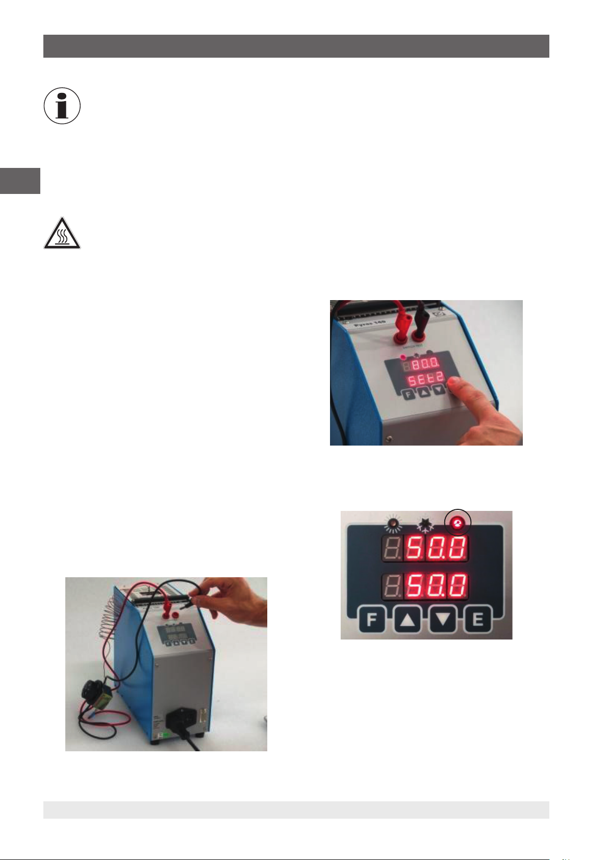
6.6 Setting a set temperature
1. Insert the insert into the equalising block
Make sure that it does not get caught.
⇒
2. Insert the thermometer to be tested into the sleeve.
Here, also ensure that this doesn't get caught.
⇒
3. With the [▲] or [▼] button, enter the set point.
4. Confirm the entry with the [E] button.
The built-in heating or cooling elements will temper the metal
block automatically from room temperature to the controller's
set temperature.
If the temperature has stabilised, this will be shown by the
STABILITY-LED blinking in the lower right of display 1.
6.7 Testing or calibrating temperature probes
WARNING!
Risk of burns!
Touching the hot metal block or the test item can
lead to acute burns.
▶
During the use of the calibrator, do not touch
the upper grille, the inserts or temperature
probes because they may be very hot.
6.7.1 Testing of temperature probes
To test temperature probes, connect a separate temperature
measuring instrument to the test item. By comparing the
temperature displayed on the external measuring instrument
with the reference temperature, there is evidence of the
status of the test item. Here, pay attention to the fact that the
test item requires a short time until it reaches the temperature
of the metal block.
At the end of the test, DO NOT remove the probe while it is
still at high temperature. First. cool the calibrator while the
probes are still inserted, see chapter 6.9 “Cooling down the
metal block”.
Before returning the calibrator to its case make sure that,
the temperature of the block is almost the same as ambient
temperature.
6.7.2 Calibrating temperature probes
Calibrations with a temperature dry-well calibrator can be
performed with the internal reference of the calibrator. Should
a better accuracy need to be achieved, working with an
external reference is required. With the second option the
external reference and the test item should be located on the
same height and near together.
6.7.3 Positioning the temperature probe
Insert the temperature probe, together with the matching
insert, into the temperature dry-well calibrator.
The insert is manufactured from aluminium or brass and has
one or more holes so that a large number of temperature
probes can be calibrated in this insert. This insert has the
function of distributing the temperature evenly.
It is therefore also possible to calibrate temperature probes
with different lengths so long as the depth of the holes has
been adjusted.
▶
After setting up the calibrator, insert the insert carefully
into the holder.
Ensure that no dirt or other foreign materials can get
⇒
between the block and the insert.
12 WIKA operating instructions, model CTD4000
14366831.01 05/2020 EN/DE
Page 15
6. Commissioning, operation
The insert replacement tool is a curved pair of pliers that can
be hooked into the holes provided in the top of the insert. The
insert must be aligned in such a way, so that the grooves sit
directly over the controlling and monitoring thermometers.
In order to achieve the best result from the calibration, the
following points must be observed:
■
Diameter of the temperature probe being checked
■
The bore diameter of the insert should be larger than the
that of the temperature probe to be calibrated
Max.
temperature
600 °C 4.5 ... 8 mm 0.5 mm
600 °C 8 ... 12 mm 0.7 mm
600 °C 12 ... 17 mm 1 mm
< 300 °C 4.5 ... 14 mm 0.3 mm
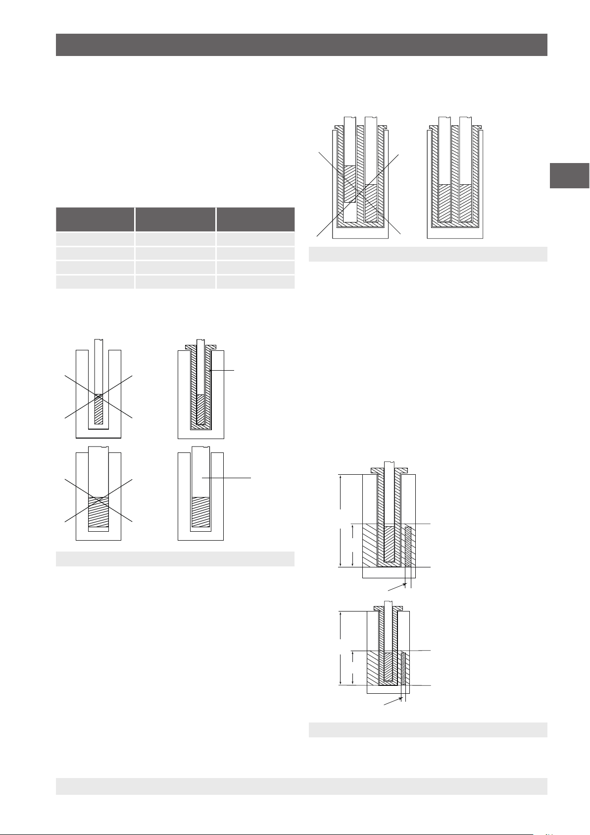
If this is not possible, use reducing blocks with the abovementioned tolerances (see figure 1).
Probe diameter Tolerances of
No
the bores
Reducing
block
Yes
The sensitive element of the temperature probe is oriented
optimally when it sits on the bottom (see figure 2).
YesNo
Figure 2
6.7.4 Calibration with one reference
If the length of the temperature probe is shorter than the
depth of the bore, then the reference should also be placed
at the height of the test item.
Further preconditions for the calibration of references:
■
The maximum temperature of the temperature probe
should be higher than the temperature of the calibrator,
otherwise the temperature probe could be destroyed.
■
Insert the test item into the insert before reaching the
target temperature, otherwise instabilities and sensor
break could result.
■
Both temperature probes must be as close to each other
as possible (see figure 3).
EN
> 0.5
No
Figure 1
▶
Avoid using bores which are too accurate and do not
press the temperature probes into the block.
▶
Clean the block and the insert before use.
▶
Only insert the temperature probe or the insert into the
block at ambient temperature using the insert replacement
tool.
14366831.01 05/2020 EN/DE
Yes
190
40
Reference probe
140
90
Reference probe
Figure 3
Calibration zone
Calibration zone
13WIKA operating instructions, model CTD4000
Page 16
6. Commissioning, operation
The temperature difference is proportional to the
diameter of the test item and the diameter of the
bore in the insert.
The time the probes take to reach the set point is
much higher as the difference in diameter from
the probes and the holes is bigger.
EN
6.7.5 After the test or the calibration
WARNING!
Risk of burns!
High temperatures can lead to acute burns.
At the end of the calibration, do not pulled out
the temperature probe from the calibrator at high
temperatures.
▶
Cool down the calibrator, including the
temperature probe, so that thermal shock
is prevented, as described in chapter 6.9
“Cooling down the metal block”.
▶
Before the calibrator is switched off, check
whether the temperature is almost the same
as the ambient temperature.
3. Switch on instrument.
4. With the [▲] or [▼] button, enter the set point, which
corresponds to T
5. Confirm the entry with the [E] button.
6. With the [F] button, select the function SEt2.
7. With the [▲] or [▼] button, enter the set point T
8. Confirm the entry with the [E] button.
The temperature of the thermostat switch should be
⇒
between T
9. With the [F] button, call the Grd (degrees per minute)
function.
10. With the [▲] or [▼] button, enter the value for the heating
rate of change.
Low values are preferable for a more accurate test
⇒
(e.g. values less than 1 °C per minute).
11. Confirm the entry with the [E] button.
min
.
min
and T
max
.
max
.
1. With the [▲] or [▼] button, enter the room temperature.
2. Confirm the entry with the [E] button.
Remove the insert from the calibrator after the use. Humidity
may cause verdigris to build up on the inside of the insert
within the metal block
In this case, the insert can become stuck.
⇒
6.8 Switch test function
With the "SWITCH TEST" function, it is possible to control
the open and close temperature of the thermostat:
1. Insert the thermostat sensor into a suitable bore in the
insert.
2. Connect the thermostat to the switch test input.
The switch test LED will indicate the status of the switch:
The LED is lit = LED ON with switch closed
14 WIKA operating instructions, model CTD4000
14366831.01 05/2020 EN/DE
Page 17
6. Commissioning, operation
The LED isn't lit = LED OFF with switch open
1. With the [F] button, select the function run.
2. With the [▲] or [▼] button, set to ON.
■
By entering run OFF, the switch test is ended.
6.9 Cooling down the metal block
WARNING!
Risk of burns!
High temperatures at the metal block or at the
temperature probe can lead to acute burns.
▶
Before transporting or touching the metal
block and/or calibration instruments, make
sure that they have cooled down sufficiently.
▶
In order that the calibration instruments can
be brought quickly from a higher to a lower
temperature, set the set temperature to a
lower temperature (e.g. room temperature).
▶
In order to cool down the metal block, set the
set temperature to a low temperature, e.g.
room temperature.
EN
When the LED in this function flashes, this indicates that the
process is active.
■
The thermostat’s release values are recorded in the
parameters SOn and SOFF.
■
Temperature runs between T
function is switched off. The SOn and SOFF values are
continuously updated during each run.
max
and T
until the
min
1. With the [▲] or [▼] button, enter the room temperature.
2. Confirm the entry with the [E] button.
The installed fan gently and automatically switches to a
higher speed thus providing more cooling air.
After switching off or removing the mains
connection, no cooling air will be provided by
the built-in ventilator. If the voltage supply is
interrupted during the cooling process, sufficient
thermal decoupling is still guaranteed between
the metal block and the case.
14366831.01 05/2020 EN/DE
15WIKA operating instructions, model CTD4000
Page 18

7. Operating the calibrator
7. Operating the calibrator
7.1 Setting a temporary set temperature (set-point
mode)
Setting the set temperature:
■
Pressing the [▲] button increases the set point.
■
Pressing the [▼] button lowers the set point.
■
EN
The button [E] confirms the entry.
Before each calibration, you must wait until a stable set point
is reached.
7.2 Programming (main menu)
All the settings can be carried out in this menu structure.
1. Press button [F].
This opens the main menu.
⇒
2. With the button [F] select the desired entry in the main
menu (see overview).
3. Confirm the entry with the [E] button.
7.3 Short description of the menu
The calibrator has four menu levels:
■
First menu level: General settings
■
Second menu level: Settings for optimising the control
■
Third menu level: Recalibration of the instrument
■
Fourth menu level: Settings of the temperature controller
16 WIKA operating instructions, model CTD4000
14366831.01 05/2020 EN/DE
Page 19
7. Operating the calibrator
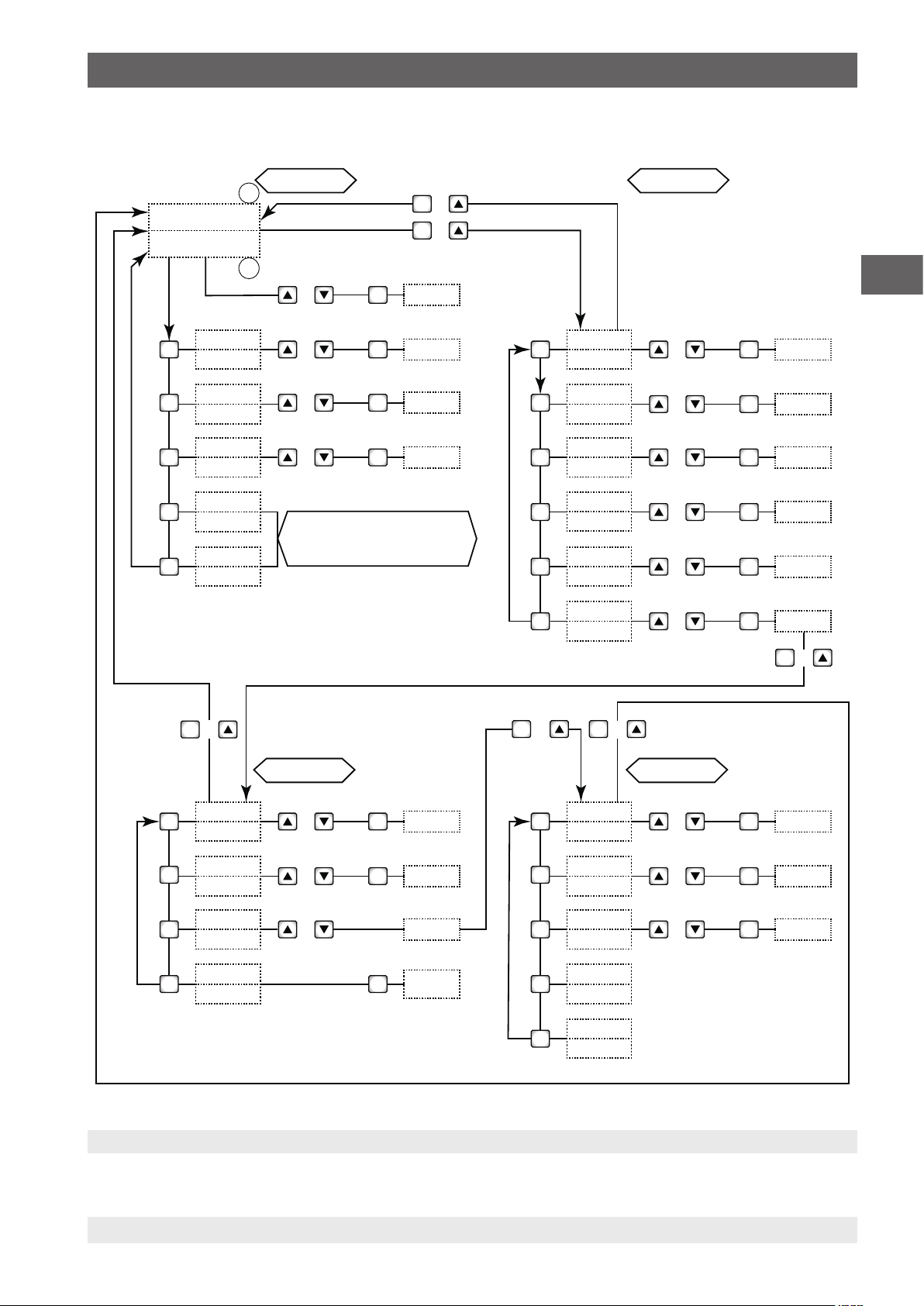
7.3.1 Menu structure, parameter levels
LEVEL 1 LEVEL 2
1
TEMPERATURE VALUE
SET POINT
2
or
E
+
F
+
F
NEW VALUE
EN
VALUE
F
F
F
F
F
F
SEt2
VALUE
Grd
VALUE
run
VALUE
SOn
VALUE
SOFF
+
or
or
or
CLOSING THERMOSTAT
TEMPERATURE
(IF CONNECTED)
E
E
E
NEW VALUE
NEW VALUE
NEW VALUE
F
VALUE
F
F
F
F
F
F
+
Pb
VALUE
td
VALUE
ti
VALUE
dEG
VALUE
dEF
VALUE
CodE
F
+
or
or
or
or
or
or
E
E
E
E
E
E
NEW VALUE
NEW VALUE
NEW VALUE
NEW VALUE
NEW VALUE
Code = 2
+
F
LEVEL 3 LEVEL 4
F
F
F
F
Menu structure
14366831.01 05/2020 EN/DE
VALUE
Pc
VALUE
SEtH
VALUE
CodE
clt
tbl
or
or
or
E
E
E
NEW VALUE
NEW VALUE
Code = 3
Clearing
Table
VALUE
F
F
F
F
F
tSEt
VALUE
Hy
VALUE
Stby
VALUE
Cod1
VALUE
Cod2
or
or
or
E
E
E
NEW VALUE
NEW VALUE
on / off
17WIKA operating instructions, model CTD4000
Page 20
7. Operating the calibrator
7.3.2 First menu level - General settings
▶
By pressing the [F] button, menu level 1 is accessed.
▶
With the [F] button, the menu functions can be scrolled through.
Function Meaning
SP Set point
Setting the set temperature.
EN
SEt2 Set point 2
Grd Gradient
1. With the [▲] or [▼] button, set the set point.
2. Confirm the entry with the [E] button.
Setting of set temperature 2, which the calibrator should approach with a certain gradient within a ramp.
1. With the [▲] or [▼] button, set the set point 2.
2. Confirm the entry with the [E] button.
The value of SEt2 must be always higher than SP.
Heating or cooling change rate during the change of the temperature value SP to SEt2 or SEt2 to SP.
1. With the [▲] or [▼] button, set the gradient.
2. Confirm the entry with the [E] button.
The gradient must be smaller than the maximum specified value in the technical specifications (max.
15 °C/min).
run Switch test
1. With the [▲] or [▼] button, select ON or OFF.
2. With the [E] button, start or stop the switch test.
The temperature dry-well calibrator reaches temperature SP2 from SP with the selected heating rate of
change. The basis is the same temperature with which the ramp was confirmed. If the value of SP2 is lower
than the SP, the calibrator will not accept the run and the instrument will display “Err”. The LED will flash to
indicate that the function is active. The set point will change the value following the selected slope rate. When
the internal temperature reaches the SEt2 set point, the internal temperature will decrease with the cooling
slope rate; the SP value will be considered as the new set point. During the ramp program, the derivative
parameter will not be considered. During the ramp program, the LED on the right of the set point flashes and
the set point increases or decreases the value.
18 WIKA operating instructions, model CTD4000
14366831.01 05/2020 EN/DE
Page 21

7. Operating the calibrator
Function Meaning
Example for a ramp program
A thermostat with an expected switch range between 120 and 100 °C will be tested.
SP = 100 °C; SP2 = 120 °C; gradient = 2 °C/min.
1. With the [▲] or [▼] button, set SP to 100 °C.
2. Confirm the entry with the [E] button.
3. Press button [F].
4. With the [▲] or [▼] button, set SP2 to 120 °C.
5. Confirm the entry with the [E] button.
6. Press button [F].
7. With the [▲] or [▼] button, set GRD to 2 °C/min.
8. Confirm the entry with the [E] button.
9. Press button [F].
10. With the [▲] or [▼] button, set run to ON.
11. Confirm the entry with the [E] button.
After pressing the [E] button to confirm the start of the ramp, the oven temperature will ascend with the
⇒
heating slope rate. The temperature oscillates between 100 and 120 °C until run OFF is selected. Of
course, there will be some oscillations at the beginning since the ramp slope will not be suitable, but
these only last a short time and then the oven temperature will follow the ramp’s set point.
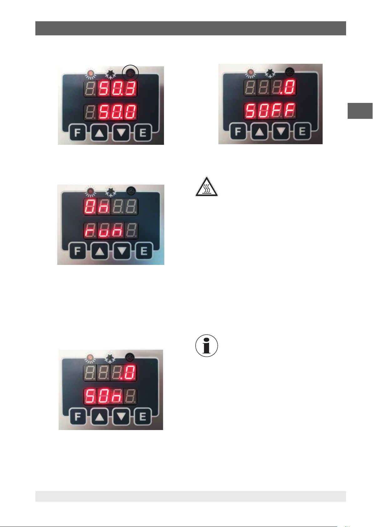
SOn Switch on
Displays the temperature at which the temperature switch contact closes.
Displays the temperature at which the thermostat would be connected to the terminals.
“SWITCH TEST” has been closed.
SOFF Switch off
Displays the temperature at which the temperature switch opens.
Displays the temperature at which the thermostat would be connected to the terminals.
“SWITCH TEST” has been opened.
The values of SOn and SOFF will change at each loop or each time you select “run OFF”.
EN
7.3.3 Second menu level - Settings for optimising the control
▶
By pressing the [F] and [▲] buttons at the same time, the 2nd level menu is accessed.
▶
With the [F] button, the menu functions can be scrolled through.
▶
By pressing the [F] and [▲] buttons at the same time or waiting for 20 seconds, you return to the main menu.
Function Meaning
Pb Value of the Proportional band in percentage of the end value.
1. With the [▲] or [▼] button, set the proportional band.
2. Confirm the entry with the [E] button.
Proportional band means the length of time in the measurement field within which there is the variation of the
regulation probe output alarm and therefore the adjustment of the heating element power.
td Derivative time in seconds
1. With the [▲] or [▼] button, set the derivative time in seconds.
2. Confirm the entry with the [E] button.
When there is a step variation of temperature, the derivative action induces a greater initial adjustment, so that
the oven will have a greater power than it usually has due to the proportional and integral action only. Since
the error persists, the derivative action reduces the impact giving the integral action the task of reducing the
error.
14366831.01 05/2020 EN/DE
19WIKA operating instructions, model CTD4000
Page 22

7. Operating the calibrator
Function Meaning
ti Integral time in seconds
1. With the [▲] or [▼] button, set the integral term in seconds.
2. Confirm the entry with the [E] button.
The integral action eliminates the error between the selected set point and the temperature reached through
EN
dEG Selection of the unit in which the temperature should be shown on the display.
dEF Factory setting (default parameters)
the proportional action alone. Integral time means the length of time the integral action needs to double the
proportional term, where the default parameters will be maintained.
1. With the [▲] or [▼] button, select the unit.
The selection is between °C and °F
⇒
2. Press the [E] button to accept the unit.
The controller can be operated with factory-set or customer specific control parameters for P.B./T.I./T.D..
■
OFF = customer-specific control parameter
■
ON = factory setting
The controller has been tuned optimally in the factory. For any other requirements, please contact
WIKA directly.
By selecting the “OFF” parameter and confirming with the [E] button, the setting parameters can be changed,
which then remain active even if the calibrator is turned off. By selecting the “ON” button (followed by
confirmation by pressing the [E] button) the setting values will be set to the factory default ones specified by
the manufacturer, and these can no longer be changed. By switching the calibrator off, the parameter will set
to OFF, but the factory default parameters will be maintained.
CodE Access code for the functions in the third menu level (default = 2)
1. With the [▲] or [▼] buttons, input the password (default = 2).
2. Press the [F] and [▲] buttons at the same time.
The third menu level will be accessed.
⇒
The access code in the fourth menu level, is changed via the serial interface in the parameter
"Cod1".
If the access code is lost, this can be read via register 13.
7.3.4 Third menu level - Recalibration of the instrument
▶
Via the second menu level and the "CodE" function, one can access the third menu level.
▶
With the [F] button, the menu functions can be scrolled through.
▶
By pressing the [F] and [▲] buttons at the same time or waiting for 20 seconds, you return to the main menu.
Function Meaning
Pc Calibration point
1. With the [▲] or [▼] button, set the value read with the standard thermometer.
2. Confirm the entry with the [E] button.
SetH Maximum temperature setting of the set point
(not adjustable)
20 WIKA operating instructions, model CTD4000
14366831.01 05/2020 EN/DE
Page 23

7. Operating the calibrator
Function Meaning
CodE Access code for the functions in the fourth menu level (default = 3)
1. With the [▲] or [▼] buttons, input the password (default = 3).
2. Press the [F] and [▲] buttons at the same time.
The fourth menu level will be accessed.
⇒
The access code in the fourth menu level, is changed via the serial interface in the parameter
"Cod2".
If the access code is lost, this can be read via register 20.
Tbl Clearing of the calibration table
In the display Clr will be shown.
▶
With the [E] button, delete the calibration points entered with the Pc function.
7.3.5 Fourth menu level - Settings of the temperature controller
▶
Via the third menu level and the "CodE" function, one can access the fourth menu level.
▶
With the [F] button, the menu functions can be scrolled through.
▶
By pressing the [F] and [▲] buttons at the same time or waiting for 20 seconds, you return to the main menu.
Function Meaning
tSET Set point of the temperature controller
1. With the [▲] or [▼] button, set the set point.
2. Confirm the entry with the [E] button.
The value has been preset by the manufacturer.
EN
Hy Hysteresis of the temperature controller
1. With the [▲] or [▼] button, set the hysteresis.
2. Confirm the entry with the [E] button.
The value has been preset by the manufacturer.
Stby Initial delay time
If the value “OFF” is set in commissioning, the calibrator immediately calls up the last set point selected
prior to turning off. If the value “ON” is set in commissioning, the calibrator enters the waiting setting and
SP flashes. It is necessary to press any button in order to move it from the waiting position and to choose
the desired set point.
Cod1 Access code for the third menu level
(default = 2)
Cod1 can only be changed over the serial interface.
Cod2 Access code for the fourth menu level
(default = 3)
Cod2 can only be changed over the serial interface.
14366831.01 05/2020 EN/DE
21WIKA operating instructions, model CTD4000
Page 24
8. Serial communication
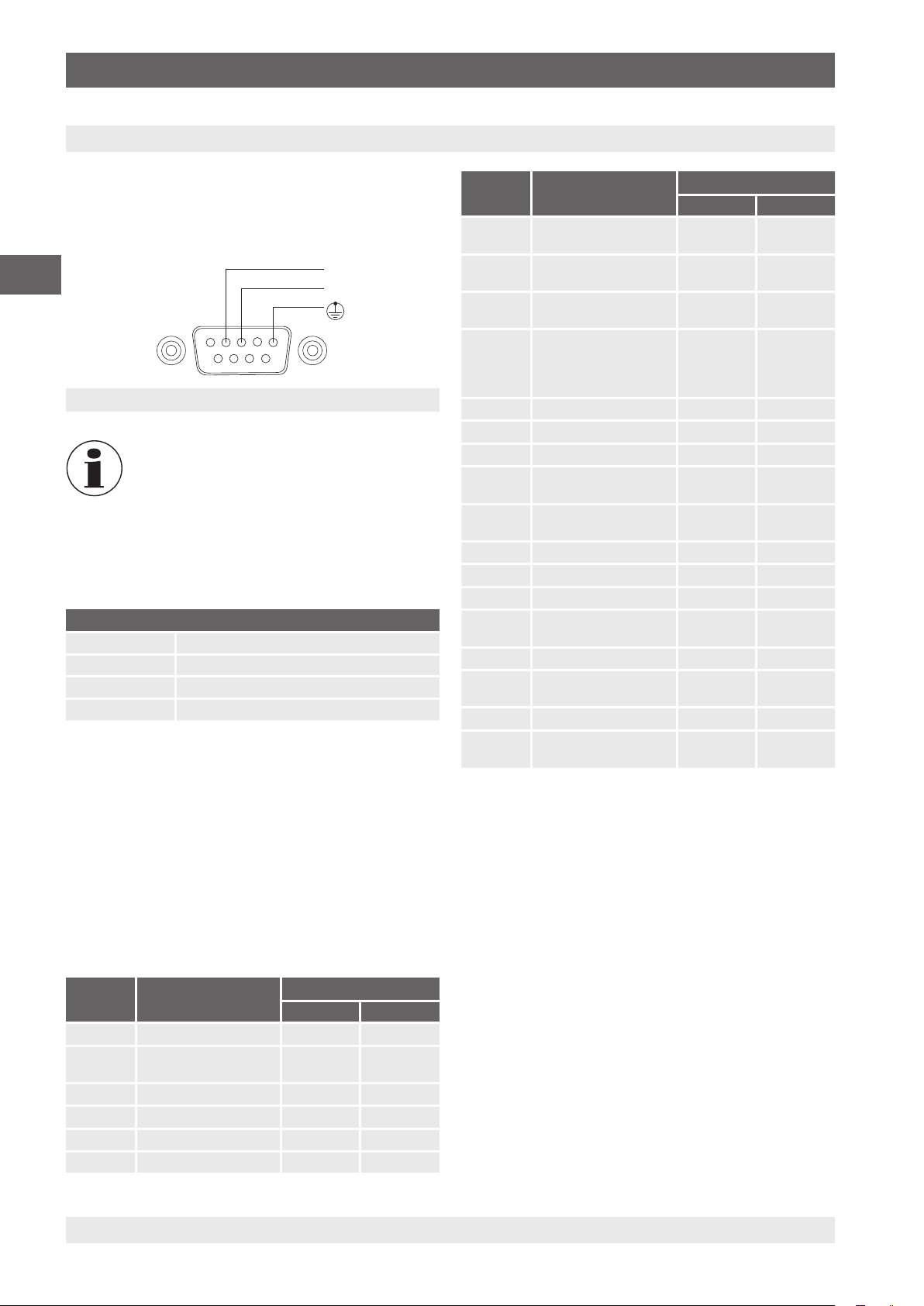
8. Serial communication
On the front of the calibrator there is a 9-pole socket
connected to the temperature controller, which enables the
calibrator to be completely controlled by a PC (see figure) by
the RS-232 input.
EN
4
21
6
5
3
7
8 9
Rx
Tx
Pin assignment, front view
The external PC must comply with the IEC 950
standard.
▶
After switching the calibrator on and connecting the serial
interface, wait until the system has booted up.
▶
To activate the serial communication, press the [E] button
on the display.
General characteristics
Baud rate 9600
N. Bit 8
Parity No
Stop bit 1
The communication operates in half-duplex format which
means that transmission and reception cannot happen
simultaneously.
The controller replies only after receiving a command; it
never replies by itself.
Variable Designation Parameters
Adjustable Readable
7 Derivative time in
seconds
10 Units 0 = °C
13 Cod1 (access key)
2 = preset
14 Baud rate
9600 (preset)
15 Address
16 Serial number
19 Min. set point -
20 Cod2
3 = preset
21 Delay ON
22 Switch-on temperature -
23 Switch-off temperature -
24 Firmware version -
27 Internal sensor type - 0 = Pt100
28 Stability range -
29 Stability symbol - 0 = no
31 Alarm setting -
33 Offset of ambient
temperature
xxx
1 = °F
- 2400
- 3
OFF
-
0 = °C
1 = °F
4800
9600
19200
2 = type K
1 = yes
Each commands string is ASCII character succession.
First is $ character; the next must indicate the instrument
address (default 1) and then is the command (4 characters).
The command and reply are ASCII character strings, as
detailed below. The communication program will be able
to convert ASCII to decimal to extract numeric values. The
default address is 1.
8.1 List of the variables and parameters
Possibility
RVAR = Data reading
WVAR = Data writing
The final part of string depends on the type of command. The
character <cr> concludes the sequence.
Variable Designation Parameters
Adjustable Readable
0 Set point x ... 9999
1 Ramp 1 = On
0 = Off
2 Set point 2 x ... 9999
3 Gradient x ... 9999
5 Proportional band 0 ... 100 %
6 Integral time in seconds xxx
1 = On
0 = Off
22 WIKA operating instructions, model CTD4000
14366831.01 05/2020 EN/DE
Page 25

8. Serial communication
8.2 Data reading
For reading, use the command RVAR.
Example:
Read the current set point (variable 0):
The command string is $1RVAR0_<cr>
Meaning of the command character string
$ = Start of message
1 = Instrument address
RVAR = Read command
0 = Number of the variable to read (see table)
_ = Space
<cr> = End of message
Response (example for 110.0 °C/°F)
The response string is: *1_110.0
The character <cr> concludes the message.
Meaning of the response character string
* = Start of the response
1 = Instrument address
_ = Space
110.0 = Numerical value of data with the character [.]
in order to separate the decimal part of the
number
<cr> = End of message
The response does not include the measure unit. To read the
unit read the variable 10:
The command string is $1RVAR10_<cr>
The response string is *1_0 for °C
The response string is *1_1 for °F
At reception of the command, the answer of the instrument is:
*1<cr>
This string shows the recognition of the command.
If the unit of the temperature is not °C, the
variable 10 for "Units" must first be set to "0".
EN
The command string for this is: $1WVAR10_0<cr>
Integers as variables
We have just shown the procedure for the writing of a float
data.
The variables 1 and 10 have two or more states (for example,
the unit) and to activate them it is necessary to assign these
variables the number corresponding to the one which should
be set, according to the table indicated below:
Variable Designation Parameters
1 Ramp 1 = ON 0 = OFF
10 Units 0 = °C 1 = °F
Example
The variable 1 corresponds to the activation of the ramp. If
you want to set it to ON in order to activate the ramp, you
should assign the value 0, otherwise the value 1.
The command string is: $1WVAR1_1<cr>
Do likewise for the other variables.
8.3 Data writing (FLOAT VARIABLES)
For reading, use the command WVAR.
Example:
Writing the set point to 132.4 °C (variable 0):
If the unit of the temperature is already °C, it is
sufficient to write the set point
The command string is: $1WVAR0_132.4<cr>
Meaning of the command character string
$ = Start of message
1 = Instrument address
WVAR = Writing command
0 = Number of the settable variable (see table)
_ = Space
132.4 = Numerical value of data with the character [.]
in order to separate the decimal part of the
number
<cr> = End of message
14366831.01 05/2020 EN/DE
23WIKA operating instructions, model CTD4000
Page 26

9. Faults
9. Faults
Personnel: Skilled personnel
Protective equipment: Protective gloves
For contact details see chapter 1 “General
information” or the back page of the operating
EN
instructions.
WARNING!
Physical injuries and damage to property
and the environment caused by high
temperatures
In the event of a defect, extreme temperatures
can be present at the instrument.
▶
Wear the requisite protective equipment.
Error Causes Measures
No function
The calibrator does not respond
when the power cord is
connected and the switch is on.
The fuse tripped as the
instrument was switched on
The voltage supply is not established correctly Check voltage supply
The fuse is defective Replacing the fuse
The power cord is defective Replace the power cord with an equivalent
The main switch is faulty Send in for repair
The fuse is wrong Check that the proper fuse is inserted for
CAUTION!
Physical injuries and damage to property
and the environment
If faults cannot be eliminated by means of the
listed measures, the instrument must be taken
out of operation immediately.
▶
Contact the manufacturer.
▶
If a return is needed, please follow the
instructions given in chapter 11.2 “Return”.
the supply voltage and replace the fuse, if
necessary.
The main switch is faulty Send in for repair
Short-circuit in the heating element
Final temperature is not reached The solid-state relay or the heating element is
faulty
The overtemperature switch has tripped
The display is working properly
but the temperature does not
increase and the calibrator
displays error code Ht.
The display is working properly
but the temperature does not
increase and the calibrator
indicate Err after few seconds.
The display shows a different
temperature than is present in the
block
The temperature exceeds the set
point
The calibrator is barely cooling
down
The safety thermostat has been triggered for
over temperature
The heater is faulty Press any button to see if restore the heating.
The temperature controller is faulty Replace the temperature controller
The internal probe is not calibrated Return the temperature dry-well calibrator for
The controller is defective Send in for repair
The control circuit board is defective Send in for repair
The controller is defective Send in for repair
Fan is defective
Send in for repair
Verify the set point of the safety thermostat Set:
Ref to the level 4 of the menu.
Send in for repair
calibration
810 or 786 appears on the display. Internal probe is faulty Send in for repair
24 WIKA operating instructions, model CTD4000
14366831.01 05/2020 EN/DE
Page 27

10. Maintenance, cleaning and recalibration
10. Maintenance, cleaning and recalibration
Personnel: Skilled personnel
Protective equipment: Protective gloves
For contact details see chapter 1 “General
information” or the back page of the operating
instructions.
10.1 Maintenance
The instrument described here is maintenance-free.
Repairs must only be carried out by the manufacturer.
This does not apply to the fuse replacement (see chapter
4.5 “Fuse”).
Before replacing the fuse, disconnect the
temperature dry-well calibrator by unplugging the
power cord from the mains socket.
Only use original parts (see chapter 13 “Accessories”).
10.2 Cleaning
CAUTION!
Physical injuries and damage to property
and the environment
Improper cleaning may lead to physical injuries
and damage to property and the environment.
Residual media in the instrument can result in a
risk to persons, the environment and equipment.
▶
Wear the requisite protective equipment.
▶
Carry out the cleaning process as described
below.
▶
Clean the calibrator only when it is cold.
1. Cool down the temperature dry-well calibrator as
described in chapter 6.9 “Cooling down the metal block”.
2. Before cleaning the temperature dry-well calibrator, switch
it off and isolate it by unplugging the power cord from the
mains socket.
3. Clean the instrument with a moist cloth.
Electrical connections must not come into contact with
moisture.
CAUTION!
Damage to the instrument
Improper cleaning may lead to damage to the
instrument!
▶
Do not use any aggressive cleaning agents.
▶
Do not use any hard or pointed objects for
cleaning.
Cleaning calibrators with inserts
With calibrators with inserts, during operation, a small
amount of abrasion dust can cause the block and the insert
to become jammed. To prevent this, on a regular basis and
before any long period out of use, remove the insert from
the calibrator heating block. Blow out heating block bores
with compressed air and clean the bore and insert with a dry
cloth.
Liquid or oil inside the block lead to oxides
or verdigris on the insert with use at high
temperature. In this case, the insert could
become stuck.
Liquid which may penetrate the calibrator can
cause damage or lead to the build-up of toxic
fumes.
Cleaning of the fan grille
On the base of each calibrator is a dense air grille, through
which the cooling air is supplied to the calibrator. Depending
on the cleanliness of the air, clean the grille at regular
intervals by vacuuming or brushing.
External cleaning
Clean the outside of the instrument with a damp cloth and
some water, or with a solvent-free light detergent.
10.3 Recalibration
DKD/DAkkS certificate - official certificates:
The temperature dry-well calibrator has been adjusted and
tested before delivery using measuring devices that are
traceable to nationally recognised standards.
On the basis of DIN ISO 10012, the temperature dry-well
calibrator, depending on the application, should be verified at
appropriate periodic intervals.
We recommend that the instrument is regularly recalibrated
by the manufacturer, with time intervals of approx. 12 months
or approximately 500 hours of operation.
The basic settings will be corrected if necessary.
The basis of the recalibration is the guidelines of the German
Calibration Service, DKD R5-4. The measures described
here should be used and followed for recalibration.
EN
4. Clean the instrument, in order to protect persons and the
environment from damage through residual media.
14366831.01 05/2020 EN/DE
25WIKA operating instructions, model CTD4000
Page 28

10. Maintenance, cleaning and recalibration
10.3.1 Calibration of the internal probe by the user
By calibrating yourself, the parameters of the
internal reference probe are re-determined or
adjusted. The accuracy is thus dependent upon
the reference used.
WIKA can thus no longer guarantee the
EN
Calibration can be carried out directly on the keyboard of the
instrument. The calibration is done by adjusting the internal
probe at one or more points of the range using a standard
thermometer.
The calibration is possible only by setting the temperature
unit to “°C”.
The purpose of recalibration is to correct the error between
the temperature indicated and the value of a standard
thermometer.
accuracies specified in the specifications.
As soon as these changes are carried out, the
current calibration certificate (if it was delivered
with it) loses its validity.
To calibrate the internal probe, it is necessary to have a
standard thermometer with a precision greater than the
calibrator to follow the instructions below.
1. Insert the standard thermometer probe in the most
suitable hole of the calibrator.
2. Depending on the measuring range of the instrument
or the external area in which the calibration should be
carried out, define a minimum of 5 calibration points or
several calibration points (max. 10 points).
3. Set the first calibration point and wait for the calibrator to
be stable (see the stability LED).
4. Enter menu level 3 (see 7.3.4 “Third menu level Recalibration of the instrument”) and select PC.
5. With the [▲] or [▼] button, set the value read with the
standard thermometer
6. Confirm the entry with the [E] button.
Confirmation is indicated by a beep.
⇒
7. Repeat the steps 3 ... 6 for the other points.
8. At the end of the operation, wait for approx. 20 seconds to
come back to the main menu.
At the end of the calibration DO NOT remove the standard
thermometer if the calibrator is still at high temperature. First,
cool the calibrator while the probes are still inserted, see
chapter 6.9 “Cooling down the metal block”.
Model Possible calibration points
CTD4000-140 -15, 0, +50, +100 and +125 °C [5, 32, 122, 212 and 257 °F]
CTD4000-375 50, 120, 190, 260 and 340 °C [122, 248, 374, 500 and 644 °F]
CTD4000-650 100, 200, 300, 400, 500 and 600 °C [212, 392, 572, 752, 932 and 1,112°F]
14366831.01 05/2020 EN/DE
26 WIKA operating instructions, model CTD4000
Page 29

11. Dismounting, return and disposal
11. Dismounting, return and disposal
Personnel: Skilled personnel
Protective equipment: Protective gloves
WARNING!
Physical injuries and damage to property
and the environment through residual media
Residual media on or in the instrument can
result in a risk to persons, the environment and
equipment.
▶
Wear the requisite protective equipment.
▶
Observe the information in the material safety
data sheet for the corresponding medium.
▶
Clean the instrument, in order to protect
persons and the environment from damage
through residual media.
11.1 Dismounting
WARNING!
Risk of burns
During dismounting there is a risk of high
temperatures.
▶
Let the instrument cool down sufficiently
before dismounting it!
▶
In order to cool down the metal block, set the
set temperature to a low temperature, e.g.
room temperature.
DANGER!
Danger to life caused by electric current
Upon contact with live parts, there is a direct
danger to life.
▶
The dismounting of the instrument may only
be carried out by skilled personnel.
▶
Disconnect test and calibration installations
once the system has been isolated from
power sources.
11.2 Return
Strictly observe the following when shipping the
instrument:
All instruments delivered to WIKA must be free from any
kind of hazardous substances (acids, bases, solutions, etc.)
and must therefore be cleaned before being returned, see
chapter 10.2 “Cleaning”.
When returning the instrument, use the original packaging or
a suitable transport packaging.
To avoid damage:
1. Wrap the instrument in an antistatic plastic film.
2. Place the instrument, along with the shock-absorbent
material, in the packaging. Place shock-absorbent
material evenly on all sides of the transport packaging.
3. If possible, place a bag, containing a desiccant, inside the
packaging.
4. Label the shipment as transport of a highly sensitive
measuring instrument.
Information on returns can be found under the
heading “Service” on our local website.
11.3 Disposal
Incorrect disposal can put the environment at risk.
Dispose of instrument components and packaging materials
in an environmentally compatible way and in accordance with
the country-specific waste disposal regulations.
Do not dispose of with household waste. Ensure
a proper disposal in accordance with national
regulations.
EN
1. Cool down the temperature dry-well calibrator as
described in chapter 6.9 “Cooling down the metal block”.
2. Switch off the temperature dry-well calibrator and pull out
the mains plug from the mains socket.
After switching off or after removing the mains
connection, the installed fan can no longer
provide cooling air. If the voltage supply is
interrupted during the cooling process, sufficient
thermal decoupling is still guaranteed between
the metal block and the case.
14366831.01 05/2020 EN/DE
27WIKA operating instructions, model CTD4000
Page 30

12. Specifications
12. Specifications
Specifications Model CTD4000-140
Display
Temperature range -24 ... +140 °C [-11 ... +284 °F]
Accuracy
EN
Stability
Resolution 0.1 °C
Temperature control
Heating time approx. 20 min from 20 to 120 °C
Cooling time approx. 17 min from +20 to -20 °C
Stabilisation time
Insert
Immersion depth 104 mm [4.09 in]
Insert dimensions Ø 19 x 104 mm [Ø 0.75 x 4.09 in]
Insert material Aluminium
Voltage supply
Operating voltage AC 100 ... 240 V ±10 %, 50/60 Hz
Power consumption 80 W
Fuse 2.5 A slow blow fuse
Power cord AC 230 V; for Europe
Communication
Interface RS-232
Case
Dimensions (W x D x H) 130 x 260 x 280 mm [5.12 x 10.24 x 11.02 in]
Weight 4.9 kg [10.81 lbs]
1) Is defined as the measuring deviation between the measured value and the reference value.
2) Maximum temperature difference at a stable temperature over 30 minutes.
3) Time before reaching a stable value.
1)
2)
3)
0.25 K at 100 °C [212 °F]
±0.1 K
[from 68 °F to 248 °F]
[from +68 °F to -4 °F]
dependent on temperature and temperature probe
The measurement uncertainty is defined as the total measurement uncertainty (k = 2), which contains the following shares:
Accuracy, measurement uncertainty of reference, stability and homogeneity.
28 WIKA operating instructions, model CTD4000
14366831.01 05/2020 EN/DE
Page 31

12. Specifications
Specifications Model CTD4000-375 Model CTD4000-650
Display
Temperature range t
Accuracy
Stability
Resolution 0.1 °C
Temperature control
Heating time approx. 20 min from 30 to 375 °C
Cooling time approx. 40 min from 375 to 100 °C
Stabilisation time
Insert
Immersion depth 150 mm [5.91 in]
Insert dimensions Ø 26 x 150 mm [Ø 1.02 x 5.91 in]
Insert material Aluminium Brass, nickel-plated
Voltage supply
Operating voltage AC 115/230 V ±10 %, 50/60 Hz
Power consumption 600 W
Fuse 6.3 A slow blow fuse (at AC 115 V)
Power cord AC 230 V; for Europe
Communication
Interface RS-232
Case
Dimensions (W x D x H) 130 x 260 x 280 mm [5.12 x 10.24 x 11.02 in]
Weight 5.4 kg [11.9 lbs] 6 kg [13.2 lbs]
1) Is defined as the measuring deviation between the measured value and the reference value.
2) Maximum temperature difference at a stable temperature over 30 minutes.
3) Time before reaching a stable value.
1)
2)
3)
+ 15 °C ... 375 °C [t
amb
0.35 K 0.5 K
±0.1 K ±0.3 K
[from 86 °F to 707 °F]
[from 707 °F to 212 °F]
dependent on temperature and temperature probe
Automatically switchable
3.15 A slow blow fuse (at AC 230 V)
+ 15 °F ... 707 °F] t
amb
+ 15 °C ... 650 °C [t
amb
approx. 35 min from 50 to 650 °C
[from 122 °F to 1,202 °F]
approx. 60 min from 650 to 100 °C
[from 1,202 °F to 212 °F]
+ 15 °F ... 1,202 °F]
amb
EN
The measurement uncertainty is defined as the total measurement uncertainty (k = 2), which contains the following shares:
Accuracy, measurement uncertainty of reference, stability and homogeneity.
Certificates
Certificate
Calibration
Recommended recalibration interval 1 year (dependent on conditions of use)
■
Without
■
3.1 calibration certificate per DIN EN 10204
■
DKD/DAkkS calibration certificate
Approvals and certificates, see website
For further specifications see WIKA data sheet CT 41.10 and the order documentation.
14366831.01 05/2020 EN/DE
29WIKA operating instructions, model CTD4000
Page 32

13. Accessories
13. Accessories
Inserts for model CTD4000-140 Order code
Description CTA9I-2O
Insert undrilled
Ø 19 x 104 mm [Ø 0.75 x 4.09 in]
Material: Aluminium
EN
-N-
Insert drilled
Ø 19 x 104 mm [Ø 0.75 x 4.09 in]
Drilling depth: 100 mm [3.94 in]
Material: Aluminium
Bore diameter:
1 x 3.3 mm, 1 x 4.8 mm and 2 x 6.4 mm [1 x 0.13 in, 1 x 0.19 in and 2 x 0.25 in]
Insert replacement tool -J-
-W-
Ordering information for your enquiry:
1. Order code: CTA9I-2O
2. Option:
⇓
[ ]
Inserts for model CTD4000-375 Order code
Description CTA9I-2P
Insert undrilled
Ø 26 x 150 mm [Ø 1.02 x 5.91 in]
Material: Aluminium
Insert drilled
Ø 26 x 150 mm [Ø 1.02 x 5.91 in]
Drilling depth: 145 mm [5.71 in]
Material: Aluminium
Bore diameter:
1 x 12.7 mm and 1 x 6.4 mm
[1 x 0.50 in and 1 x 0.25 in]
Bore diameter:
1 x 3.2 mm, 1 x 4.8 mm, 1 x 6.4 mm and 1 x 11.1 mm
[1 x 0.13 in, 1 x 0.19 in, 1 x 0.25 in and 1 x 0.44 in]
-N-
-O-
-P-
Insert replacement tool -J-
Ordering information for your enquiry:
1. Order code: CTA9I-2P
2. Option:
⇓
[ ]
30 WIKA operating instructions, model CTD4000
14366831.01 05/2020 EN/DE
Page 33

13. Accessories
Inserts for model CTD4000-650 Order code
Description CTA9I-2Q
Insert undrilled
Ø 26 x 150 mm [Ø 1.02 x 5.91 in]
Material: Brass, nickel-plated
-N-
Insert drilled
Ø 26 x 150 mm [Ø 1.02 x 5.91 in]
Drilling depth: 145 mm [5.71 in]
Material: Brass, nickel-plated
Bore diameter:
1 x 15.7 mm [0.62 in]
Bore diameter:
1 x 17.5 mm [0.69 in]
Bore diameter:
1 x 6.5 mm and 1 x 12.7 mm
[1 x 0.26 in and 1 x 0.50 in]
Bore diameter:
1 x 4.5 mm, 1 x 6.5 mm and 1 x 10.5 mm
[1 x 0.18 in, 1 x 0.26 in and 1 x 0.41 in]
Bore diameter:
1 x 3.2 mm, 1 x 5 mm, 1 x 6.5 mm and 1 x 9.5 mm
[1 x 0.13 in, 1 x 0.20 in, 1 x 0.26 in and 1 x 0.37 in]
Bore diameter:
1 x 3.2 mm, 1 x 5 mm, 1 x 7 mm and 1 x 9.5 mm
[1 x 0.13 in, 1 x 0.20 in, 1 x 0.28 in and 1 x 0.41 in]
Insert replacement tool -J-
-Q-
-R-
-S-
-T-
-U-
-V-
EN
Ordering information for your enquiry:
1. Order code: CTA9I-2Q
2. Option:
Description CTX-A-KB
Transport case -CC-
Ordering information for your enquiry:
1. Order code: CTX-A-KB
2. Option:
WIKA accessories can be found online at www.wika.com.
14366831.01 05/2020 EN/DE
⇓
[ ]
Order code
⇓
[ ]
31WIKA operating instructions, model CTD4000
Page 34

EN
32 WIKA operating instructions, model CTD4000
14366831.01 05/2020 EN/DE
Page 35

Inhalt
Inhalt
1. Allgemeines 37
2. Kurzübersicht 37
2.1 Überblick . . . . . . . . . . . . . . . . . . . . . . . . . . . . . . . 37
2.2 Beschreibung . . . . . . . . . . . . . . . . . . . . . . . . . . . . . . 37
3. Sicherheit 38
3.1 Symbolerklärung. . . . . . . . . . . . . . . . . . . . . . . . . . . . . 38
3.2 Bestimmungsgemäße Verwendung . . . . . . . . . . . . . . . . . . . . . . 38
3.3 Lieferumfang . . . . . . . . . . . . . . . . . . . . . . . . . . . . . . 38
3.4 Fehlgebrauch . . . . . . . . . . . . . . . . . . . . . . . . . . . . . . 39
3.5 Personalqualifikation . . . . . . . . . . . . . . . . . . . . . . . . . . . 40
3.6 Persönliche Schutzausrüstung . . . . . . . . . . . . . . . . . . . . . . . . 40
3.7 Beschilderung, Sicherheitskennzeichnungen . . . . . . . . . . . . . . . . . . . 40
4. Aufbau und Funktion 41
4.1 Übersicht der unterschiedlichen Gerätetypen . . . . . . . . . . . . . . . . . . . 41
4.2 Isometrische Ansichten . . . . . . . . . . . . . . . . . . . . . . . . . . 41
4.3 Beschreibung des Temperaturreglers. . . . . . . . . . . . . . . . . . . . . . 42
4.4 Spannungsversorgung. . . . . . . . . . . . . . . . . . . . . . . . . . . 43
4.5 Sicherung . . . . . . . . . . . . . . . . . . . . . . . . . . . . . . . 43
4.6 Heizwiderstand (CTD4000-375 oder CTD4000-650) . . . . . . . . . . . . . . . . 44
4.7 Temperatursensoren . . . . . . . . . . . . . . . . . . . . . . . . . . . 44
4.8 Sicherheitsthermostat (CTD4000-375 oder CTD4000-650) . . . . . . . . . . . . . . 44
4.9 Lüfter . . . . . . . . . . . . . . . . . . . . . . . . . . . . . . . . 44
4.10 Einsatzhülsen. . . . . . . . . . . . . . . . . . . . . . . . . . . . . . 44
5. Transport, Verpackung und Lagerung 45
5.1 Transport . . . . . . . . . . . . . . . . . . . . . . . . . . . . . . . 45
5.2 Verpackung und Lagerung . . . . . . . . . . . . . . . . . . . . . . . . . 45
6. Inbetriebnahme, Betrieb 45
6.1 Spannungsversorgung. . . . . . . . . . . . . . . . . . . . . . . . . . . 45
6.2 Einsatz bei hohen Temperaturen . . . . . . . . . . . . . . . . . . . . . . . 45
6.3 Erste Inbetriebnahme . . . . . . . . . . . . . . . . . . . . . . . . . . . 46
6.4 Betriebslage . . . . . . . . . . . . . . . . . . . . . . . . . . . . . . 46
6.5 Einschalten des Kalibrators . . . . . . . . . . . . . . . . . . . . . . . . . 46
6.6 Einstellung einer Soll-Temperatur . . . . . . . . . . . . . . . . . . . . . . . 46
6.7 Prüfen oder Kalibrieren von Temperaturfühlern . . . . . . . . . . . . . . . . . . 46
6.7.1 Prüfen von Temperaturfühlern. . . . . . . . . . . . . . . . . . . . . . . . . . . . . . . . . . . . . . 46
6.7.2 Kalibrieren von Temperaturfühlern . . . . . . . . . . . . . . . . . . . . . . . . . . . . . . . . . . . 46
6.7.3 Positionierung der Temperaturfühler . . . . . . . . . . . . . . . . . . . . . . . . . . . . . . . . . . 46
6.7.4 Kalibrieren mit einer Referenz . . . . . . . . . . . . . . . . . . . . . . . . . . . . . . . . . . . . . 47
6.7.5 Nach der Prüfung oder Kalibrierung . . . . . . . . . . . . . . . . . . . . . . . . . . . . . . . . . . 48
6.8 Schaltertest-Funktion . . . . . . . . . . . . . . . . . . . . . . . . . . . 48
6.9 Abkühlen des Metallblockes . . . . . . . . . . . . . . . . . . . . . . . . . 49
7. Bedienung des Kalibrators 50
7.1 Einstellen einer temporären Soll-Temperatur (Sollwertmodus) . . . . . . . . . . . . . 50
7.2 Programmierung (Hauptmenü) . . . . . . . . . . . . . . . . . . . . . . . . 50
7.3 Kurzbeschreibung des Menüs . . . . . . . . . . . . . . . . . . . . . . . . 50
7.3.1 Menüstruktur, Parameterebenen . . . . . . . . . . . . . . . . . . . . . . . . . . . . . . . . . . . . 51
7.3.2 Erste Menüebene - Allgemeine Einstellungen. . . . . . . . . . . . . . . . . . . . . . . . . . . . .52
DE
14366831.01 05/2020 EN/DE
35WIKA Betriebsanleitung, Typ CTD4000
Page 36

Inhalt
7.3.3 Zweite Menüebene - Einstellungen zur Optimierung der Regelung . . . . . . . . . . . . . . . . . 53
7.3.4 Dritte Menüebene - Rekalibrierung des Gerätes . . . . . . . . . . . . . . . . . . . . . . . . . . . 54
7.3.5 Vierte Menüebene - Einstellungen des Temperaturreglers . . . . . . . . . . . . . . . . . . . . . .55
8. Serielle Kommunikation 56
8.1 Liste der Variablen und Parameter . . . . . . . . . . . . . . . . . . . . . . . 56
8.2 Lesen der Daten . . . . . . . . . . . . . . . . . . . . . . . . . . . . . 57
DE
8.3 Schreiben der Daten (FLOAT-VARIABLEN). . . . . . . . . . . . . . . . . . . . 57
9. Störungen 58
10. Wartung, Reinigung und Rekalibrierung 59
10.1 Wartung. . . . . . . . . . . . . . . . . . . . . . . . . . . . . . . . 59
10.2 Reinigung . . . . . . . . . . . . . . . . . . . . . . . . . . . . . . . 59
10.3 Rekalibrierung . . . . . . . . . . . . . . . . . . . . . . . . . . . . . 59
10.3.1 Eigene Kalibrierung des Innenfühlers . . . . . . . . . . . . . . . . . . . . . . . . . . . . . . . . . 60
11. Demontage, Rücksendung und Entsorgung 61
11.1 Demontage . . . . . . . . . . . . . . . . . . . . . . . . . . . . . . 61
11.2 Rücksendung. . . . . . . . . . . . . . . . . . . . . . . . . . . . . . 61
11.3 Entsorgung . . . . . . . . . . . . . . . . . . . . . . . . . . . . . . 61
12. Technische Daten 62
13. Zubehör 64
Konformitätserklärungen finden Sie online unter www.wika.de.
36 WIKA Betriebsanleitung, Typ CTD4000
14366831.01 05/2020 EN/DE
Page 37
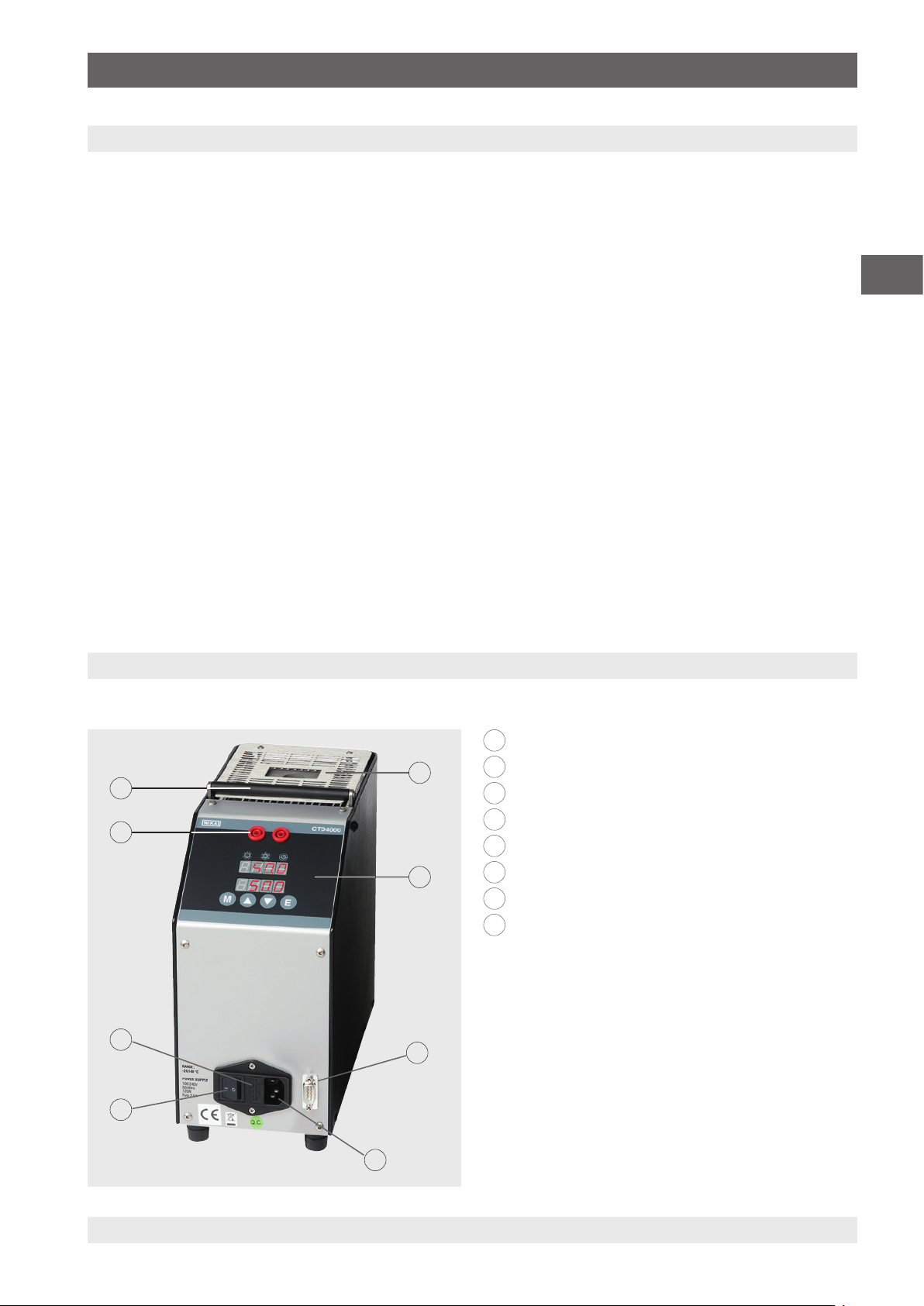
1. Allgemeines / 2. Kurzübersicht
1. Allgemeines
■
Der in der Betriebsanleitung beschriebene
Temperatur-Blockkalibrator Typ CTD4000 wird nach dem
aktuellen Stand der Technik konstruiert und gefertigt.
Alle Komponenten unterliegen während der Fertigung strengen Qualitäts- und Umweltkriterien. Unsere
Managementsysteme sind nach ISO 9001 und ISO 14001
zertifiziert.
■
Diese Betriebsanleitung gibt wichtige Hinweise zum
Umgang mit dem Gerät. Voraussetzung für sicheres Arbeiten ist die Einhaltung aller angegebenen
Sicherheitshinweise und Handlungsanweisungen.
■
Die für den Einsatzbereich des Gerätes geltenden
örtlichen Unfallverhütungsvorschriften und allgemeinen
Sicherheitsbestimmungen einhalten.
■
Die Betriebsanleitung ist Produktbestandteil und muss
in unmittelbarer Nähe des Gerätes für das Fachpersonal
jederzeit zugänglich aufbewahrt werden. Betriebsanleitung an nachfolgende Benutzer oder Besitzer des Gerätes
weitergeben.
■
Das Fachpersonal muss die Betriebsanleitung vor Beginn
aller Arbeiten sorgfältig durchgelesen und verstanden
haben.
■
Es gelten die allgemeinen Geschäftsbedingungen in den
Verkaufsunterlagen.
■
Technische Änderungen vorbehalten.
■
Werkskalibrierungen / DKD/DAkkS-Kalibrierungen erfolgen nach internationalen Normen.
■
Weitere Informationen:
- Internet-Adresse: www.wika.de / www.wika.com
- Zugehöriges Datenblatt: CT 41.10
- Anwendungsberater: Tel.: +49 9372 132-0
Fax: +49 9372 132-406
info@wika.de
DE
2. Kurzübersicht
2.1 Überblick
8
7
6
5
14366831.01 05/2020 EN/DE
1
Temperaturblock
2
1
2
Bedienoberfläche
3
RS-232-Schnittstelle
4
Netzanschluss
5
Hauptschalter
6
Sicherungshalter
7
Anschlüsse für Temperaturschaltertest
8
Tragegriff
2.2 Beschreibung
Der Kalibrator ist für Vor-Ort-Anwendungen wie auch für
die rauen Bedingungen des Marine- und Schiffbausektors
3
konzipiert.
Der thermische Teil des Kalibrators besteht aus einem
Metallblock, der mit Widerständen oder mit thermoelektrischen Peltier-Modulen geheizt/gekühlt wird. Im Metallblock
ist eine Bohrung angebracht, in denen die austauschbaren
Einsatzhülsen eingesetzt werden.
4
37WIKA Betriebsanleitung, Typ CTD4000
Page 38

2. Kurzübersicht / 3. Sicherheit
2.3 Lieferumfang
Für Temperatur-Blockkalibrator Typ CTD4000-140
■
Kalibrator
■
Netzkabel, 1,5 m [5 ft] mit Schukostecker
■
Wechselwerkzeug
■
Betriebsanleitung
■
Gebohrte Einsatzhülse mit 4 Bohrungen: 3,3 mm, 4,8 mm
DE
und 2 x 6,4 mm [0,13 in, 0,19 in und 2 x 0,25 in]
Für Temperatur-Blockkalibrator Typ CTD4000-375
■
Kalibrator
■
Netzkabel, 1,5 m [5 ft] mit Schukostecker
■
Wechselwerkzeug
■
Betriebsanleitung
■
Gebohrte Einsatzhülse mit 4 Bohrungen: 3,2 mm, 4,8 mm,
6,4 mm und 11,1 mm [0,13 in, 0,19 in, 0,25 in und 0,44 in]
3. Sicherheit
Für Temperatur-Blockkalibrator Typ CTD4000-650
■
Kalibrator
■
Netzkabel, 1,5 m [5 ft] mit Schukostecker
■
Wechselwerkzeug
■
Betriebsanleitung
■
Gebohrte Einsatzhülse mit 4 Bohrungen: 3,2 mm, 5 mm,
7 mm und 10,5 mm [0,13 in, 0,2 in, 0,28 in und 0,41 in]
Lieferumfang mit dem Lieferschein abgleichen.
3.1 Symbolerklärung
WARNUNG!
… weist auf eine möglicherweise gefährliche
Situation hin, die zum Tod oder zu schweren
Verletzungen führen kann, wenn sie nicht gemieden wird.
VORSICHT!
… weist auf eine möglicherweise gefährliche
Situation hin, die zu geringfügigen oder leichten
Verletzungen bzw. Sach- und Umweltschäden
führen kann, wenn sie nicht gemieden wird.
GEFAHR!
… kennzeichnet Gefährdungen durch elektrischen Strom. Bei Nichtbeachtung der
Sicherheitshinweise besteht die Gefahr schwerer
oder tödlicher Verletzungen.
WARNUNG!
… weist auf eine möglicherweise gefährliche
Situation hin, die durch heiße Oberflächen oder
Flüssigkeiten zu Verbrennungen führen kann,
wenn sie nicht gemieden wird.
Information
… hebt nützliche Tipps und Empfehlungen sowie
Informationen für einen effizienten und störungsfreien Betrieb hervor.
3.2 Bestimmungsgemäße Verwendung
Der portable Temperatur-Blockkalibrator Typ CTD4000 ist
eine tragbare Einheit für Vor-Ort-Anwendungen wie auch für
die rauen Bedingungen des Marine- und Schiffbausektors
konzipiert.
Der Temperatur-Blockkalibrator ist zur Kalibrierung von
Thermometern, Temperaturschaltern/Thermostaten,
Widerstandsthermometern und Thermoelementen vorgesehen.
Die Betriebssicherheit der gelieferten Instrumente ist nur
bei bestimmungsgemäßer Verwendung (Überprüfung von
Temperatursensoren) gewährleistet. Die angegebenen
Grenzwerte dürfen keinesfalls überschritten werden (siehe
Kapitel 12 „Technische Daten“).
Maximale Umgebungsbedingungen am Einsatzort:
■
Umgebungstemperatur: 5 ... 45 °C [41 ... 113 °F]
■
Feuchtigkeit: 95 % relative Feuchte (keine Betauung)
Dieses Gerät ist nicht für den Einsatz in
explosionsgefährdeten Bereichen zugelassen!
Hinweis für Geräte mit EMV und der Klasse A
Dies ist eine Einrichtung der Klasse A für Störaussendung
und ist für den Betrieb in industrieller Umgebung vorgesehen.
In anderen Umgebungen, z. B. Wohn- oder Gewerbebereich,
kann sie unter Umständen andere Einrichtungen störend
beeinflussen. In diesem Fall kann vom Betreiber verlangt
werden, angemessene Maßnahmen durchzuführen.
38 WIKA Betriebsanleitung, Typ CTD4000
14366831.01 05/2020 EN/DE
Page 39

3. Sicherheit
Das Gerät ist ausschließlich für den hier beschriebenen
bestimmungsgemäßen Verwendungszweck konzipiert
und konstruiert und darf nur dementsprechend verwendet
werden.
Die technischen Spezifikationen in dieser Betriebsanleitung
sind einzuhalten. Eine unsachgemäße Handhabung oder ein
Betreiben des Gerätes außerhalb der technischen Spezifikationen macht die sofortige Stilllegung und Überprüfung durch
einen autorisierten WIKA-Servicemitarbeiter erforderlich.
Elektronische Präzisionsmessgeräte mit erforderlicher
Sorgfalt behandeln (vor Nässe, Stößen, starken Magnetfeldern, statischer Elektrizität und extremen Temperaturen
schützen, keine Gegenstände in das Gerät bzw. Öffnungen
einführen). Stecker und Buchsen vor Verschmutzung schützen.
Ansprüche jeglicher Art aufgrund von nicht
bestimmungsgemäßer Verwendung sind ausgeschlossen.
3.3 Fehlgebrauch
WARNUNG!
Verletzungen durch Fehlgebrauch
Fehlgebrauch des Gerätes kann zu gefährlichen
Situationen und Verletzungen oder Sachschäden
führen.
▶
Eigenmächtige Umbauten am Gerät unterlassen.
▶
Gerät nicht in explosionsgefährdeten Bereichen einsetzen.
▶
Gerät nicht für abrasive und viskose
Messstoffe verwenden.
▶
Ausschließlich das mitgelieferte Netzkabel
verwenden.
▶
Betriebsparameter gemäß Kapitel 12 „Technische Daten“ beachten.
Diese Parameter dürfen nicht geändert werden, v.a.
um eine Fehlfunktion bzw. einen Ausfall zu verhindern,
welcher zu einem Schaden führen kann.
■
Den Bereich um den Kalibrator auf allen Seiten und insbesondere hinter dem Kalibrator frei halten.
■
Nichts auf den Kalibrator stellen.
■
Die Wartung des Kalibrators nur abgekühlt und ausgeschaltet durchführen.
■
Vor dem Ausschalten sicherstellen, dass der Kalibrator
auf Raumtemperatur (CTD4000-140) bzw. < 100 °C
(CTD4000-375/CTD4000-650) abgekühlt wurde.
■
Der Kalibrator darf nur abgekühlt im Tragekoffer aufbewahrt werden.
■
Bei Arbeiten mit hohen Temperaturen den Kalibrator nicht
ausschalten, da es hierdurch zu einer Überhitzung des
Schutzgitters und des Gehäuses kommen kann.
■
Keine Öle oder Flüssigkeiten verwenden, da diese zu eine
Beschädigung des Kalibrators führen.
■
Keinen Kraftstoffbehälter in die Nähe des Kalibrators
bringen.
Spannungsversorgung
■
Die Netzsteckdose muss jederzeit frei zugänglich sein!
■
Darauf achten, dass die Buchse bei Anschluss an die
Spannungsversorgung richtig geerdet werden.
■
Bei folgenden Punkten ist der Temperatur-Blockkalibrator
durch Ziehen des Netzkabels aus der Netzsteckdose von
der Netzspannung zu trennen.
▶
Vor dem Austauschen der Schmelzsicherung
▶
Vor der Reinigung
▶
Vor der Wartung/Instandhaltung
▶
Bei Gefahr
Schnittstelle
Keine Spannung an den RS-232-Eingang anschließen.
Sicherung
Die Sicherung erst nach Trennung des Netzanschlusses vom
Netz aus dem Kalibrator entnehmen.
DE
Zur Vermeidung von Verletzungen oder Sachschäden weitere
Punkte beachten:
Temperatur-Blockkalibrator
■
Den Kalibrator nur in einwandfreiem, funktionstüchtigem
Zustand betreiben.
■
Der einwandfreie und sichere Betrieb des Kalibrators setzt
sachgemäßen Transport, fachgerechte Lagerung, Aufstellung, Montage und bestimmungsgemäßen Gebrauch
sowie sorgfältige Bedienung und Wartung voraus.
■
Der Kalibrator wurde als Mess- und Regelgerät konzipiert.
Bei einem Gebrauch des Kalibrators für nicht ausdrücklich
in dieser Betriebsanleitung vorgesehene Anwendungen
müssen zusätzliche Schutzmaßnahmen getroffen werden.
■
Der elektronische µ-Prozessor ist werkseitig so konfiguriert, dass alle technischen Spezifikationen eingehalten
werden.
14366831.01 05/2020 EN/DE
Temperaturschaltertest
■
Keine Spannung an den Schaltertestanschluss anschließen.
■
Während des Tests der Thermostate keine Spannung
anschließen.
Jede über die bestimmungsgemäße Verwendung hinausgehende oder andersartige Benutzung gilt als Fehlgebrauch.
Dieses Gerät nicht in Sicherheits- oder in Not-Aus-Einrichtungen benutzen.
39WIKA Betriebsanleitung, Typ CTD4000
Page 40

3. Sicherheit
3.4 Personalqualifikation
WARNUNG!
Verletzungsgefahr bei unzureichender Qualifikation!
Unsachgemäßer Umgang kann zu erheblichen
Personen- und Sachschäden führen.
▶
Die in dieser Betriebsanleitung beschrie-
DE
benen Tätigkeiten nur durch Fachpersonal
nachfolgend beschriebener Qualifikation
durchführen lassen.
Fachpersonal
Das vom Betreiber autorisierte Fachpersonal ist aufgrund
seiner fachlichen Ausbildung, seiner Kenntnisse der Messund Regelungstechnik und seiner Erfahrungen sowie
Kenntnis der landesspezifischen Vorschriften, geltenden
Normen und Richtlinien in der Lage, die beschriebenen
Arbeiten auszuführen und mögliche Gefahren selbstständig
zu erkennen.
Spezielle Einsatzbedingungen verlangen weiteres entsprechendes Wissen, z. B. über aggressive Medien.
3.5 Persönliche Schutzausrüstung
Die persönliche Schutzausrüstung dient dazu, das Fachpersonal gegen Gefahren zu schützen, die dessen Sicherheit
oder Gesundheit bei der Arbeit beeinträchtigen könnten.
Beim Ausführen der verschiedenen Arbeiten an und mit dem
Gerät muss das Fachpersonal persönliche Schutzausrüstung
tragen.
Im Arbeitsbereich angebrachte Hinweise zur persönlichen Schutzausrüstung befolgen!
3.6 Beschilderung, Sicherheitskennzeichnungen
Der Betreiber ist verpflichtet das Typenschild lesbar zu
halten.
Typenschild (Beispiel)
Das Typenschild ist auf der Rückseite des Gerätes befestigt.
Mod.
1
Matr.
WIKA Alexander W iegand
SE & Co. KG
Alexander-Wiegand Str.30
63911 Klingenberg
Germany
www.wika.de
4
1
Typenbezeichnung
2
Frequenz in Hz
3
Leistung in W
4
Betriebsspannung
V
bar
Hz
W
2
3
Symbolerklärung
Vor Montage und Inbetriebnahme des Gerätes
unbedingt die Betriebsanleitung lesen!
Nicht mit dem Hausmüll entsorgen. Für eine
geordnete Entsorgung gemäß nationaler Vorgaben sorgen.
Die erforderliche persönliche Schutzausrüstung muss vom
Betreiber zur Verfügung gestellt werden.
Schutzhandschuhe tragen!
Schutz der Hände vor Berührung mit heißen
Oberflächen und aggressiven Messstoffen.
40 WIKA Betriebsanleitung, Typ CTD4000
14366831.01 05/2020 EN/DE
Page 41

4. Aufbau und Funktion
4. Aufbau und Funktion
4.1 Übersicht der unterschiedlichen Gerätetypen
■
CTD4000-140 (kühlen und heizen)
■
CTD4000-375 (heizen)
■
CTD4000-650 (heizen)
Der Temperatur-Blockkalibrator besteht aus einem robusten, grau-lackierten Stahlgehäuse und ist oben mit einem
Tragegriff versehen.
Das hintere Gehäuseteil enthält einen Metallblock mit
einer Bohrung 19 x 150 mm oder 26 x 150 mm, in die eine
Einsatzhülsen eingesetzt werden kann.
Mit Hilfe der Einsatzhülsen können dann Temperaturfühler
unterschiedlicher Größen kalibriert werden.
Das Heizelement heizt den Block und ein elektronischer
µ-Regler mit einem statischen Relaisausgang überprüft und
regelt die Temperatur.
Der Metallblock ist wärmeisoliert.
Ein mittig eingebauter Lüfter erzeugt eine konstante Luftströmung und erniedrigt die Temperatur des Gehäuses.
Die Luftströmung ist zweigeteilt: Ein Teil der Luft strömt
von der Rückseite des Kalibrators, während der zweite Teil
der Strömung parallel zum oberen Kalibratorgitter verläuft.
Dadurch befindet sich der Tauchschaft des Sensors oberhalb
der Einsatzhülse auf einer möglichst niedrigen Temperatur.
Das vordere Gehäuseteil enthält die komplette Elektronikeinheit zur Regelung der Referenztemperatur.
Zur Ansteuerung der Heizelemente werden Halbleiter-Relais
(SSR) verwendet.
Auf der Frontplatte befindet sich der Regler, welcher mit einer
LED-Display (2-reihig) für die Referenz- und Soll-Temperatur
ausgestattet ist.
Zur Vermeidung von Gefährdungen beim Betrieb
ist der Kalibrator mit folgenden Schutzvorrichtungen ausgestattet.
■
Temperaturregler, der einen möglichen Bruch
des Temperatursensors erkennt und die
Heizung trennt
■
Höchsttemperatur-Sicherheitsthermostat zur
Trennung des Heizungssystems
■
Schutzgitter als Berührungsschutz vor dem
Metallblock
■
Schutzsicherungen
4.2 Isometrische Ansichten
Vorder- und Oberseite
An der Oberseite des Temperatur-Blockkalibrator befindet
sich die Blocköffnung zum Einschieben der Einsatzhülse.
Der Regler mit Anzeige und Bedienung ist auf der Vorderseite des Kalibrators zu finden.
Über der Anzeige befindet sich der Temperaturschaltertest.
Im unteren Bereich sind die Netzanschlussbuchse und der
Netzschalter mit Sicherungshalter untergebracht.
Des Weiteren ist die Netzspannung und der Wert der
Schmelzsicherung angegeben.
Rechts neben dem Netzanschluss befindet sich die
RS-232-Schnittstelle.
Geräterückseite
Auf der Geräterückseite befindet sich das Typenschild und
der Lüfter.
Dieser darf in keiner Weise versperrt werden!
8
7
6
5
4
1
Temperaturblock mit Einsatzhülse
2
Lüfter
3
Typenschild
4
RS-232-Schnittstelle
5
Netzanschlussbuchse mit Hauptschalter und Sicherung
6
Temperaturregler
7
Temperaturschaltertest
8
Tragegriff, versenkbar
1
2
3
DE
14366831.01 05/2020 EN/DE
41WIKA Betriebsanleitung, Typ CTD4000
Page 42

4. Aufbau und Funktion
4.3 Beschreibung des Temperaturreglers
Bei dem Temperaturregler handelt es sich um einen
PID-Mikroprozessor, der auf -30 ... 140 °C, 0 ... 375 °C bzw.
0 ... 650 °C [-22 ... 284 °F, 32 ... 707 °F bzw. 32 ... 1.202 °F]
eingestellt werden kann. Auf der Anzeige wird die aktuelle
Temperatur und der Sollwert angezeigt.
DE
Bedienelemente
12
11
Übersicht über die Bedienelemente des Temperaturregler
Anschlüsse für Temperaturschaltertest
1
Weitere Informationen siehe Kapitel 6.8 „SchaltertestFunktion“.
Schaltertest-LED
2
Leuchtet, wenn Temperaturschalterkontakt geschlossen ist.
Anzeige 1
3
Zeigt die Ist-Temperatur oder den Wert der ausgewählten Funktion an.
Stabilitäts-LED
4
Bei blinkender LED ist die Temperatur stabil.
Anzeige 2
5
Anzeige der Soll-Temperatur
Im Funktionsmenü werden die Parameter angezeigt.
Schaltertest
6
Bei blinkender LED ist die Funktion aktiviert.
Taste [E]
7
Bestätigung des ausgewählten Wertes oder der
ausgewählten Funktion.
1
2
3
4
5
6
89 710
Taste [▼]
8
Erniedrigt den Wert, welcher auf Anzeige 1 oder Anzeige 2 dargestellt wird.
Bei Halten der Taste [▼] wird die Geschwindigkeit
erhöht.
Taste [▲]
9
Erhöhen des Wertes, welcher auf Anzeige 1 oder
Anzeige 2 dargestellt wird.
Bei Halten der Taste [▲] wird die Geschwindigkeit
erhöht.
Funktionsmenü-Taste [F]
10
Durch gleichzeitiges Drücken der Tastenkombination
[F] und [▲] wird die Menüebene 2 aufgerufen.
Mit der Taste [F] wird die Funktion aufgerufen und in
der Menüebene durchgeblättert.
Heiz-LED
11
Leuchtet, wenn der Kalibrator heizt.
Kühl-LED
12
Leuchtet, wenn der Kalibrator kühlt.
14366831.01 05/2020 EN/DE
42 WIKA Betriebsanleitung, Typ CTD4000
Page 43

4. Aufbau und Funktion
4.4 Spannungsversorgung
13 14 15 16 17
Informationen zum Kalibrator
13
Hauptschalter
14
Sicherung
15
Netzanschluss
16
RS-232-Schnittstelle
17
Weitere Informationen siehe Kapitel 8 „Serielle
Kommunikation“.
4.5 Sicherung
Die Kalibratoren sind mit folgenden Sicherungen gemäß der
Tabelle ausgestattet:
Betriebsspannung
AC 100 ... 240 V Träge Sicherung
AC 100/115 V - Träge Sicherung
AC 230 V - Träge Sicherung
Nur Sicherungen des Typs F 5 x 20 mm verwenden. Alle elektrischen Bauteile befinden sich
unterhalb des Hauptschalters.
Austausch der Sicherung
1. Sicherungskasten z. B. mit einem Schraubenzieher öffnen
und herausziehen.
CTD4000-140 CTD4000-375
CTD4000-650
-
2,5 A
6,3 A
3,15 A
DE
Spannungsversorgung für CTD4000-140
Der Kalibrator CTD4000-140 arbeitet mit einer Betriebsspannung von AC 100 ... 240 V, 50/60 Hz.
Spannungsversorgung für CTD4000-375 und
CTD4000-650
Der Kalibrator arbeitet mit einer Spannung von AC 230 V
oder AC 115 V, 50/60 Hz.
Der Kalibrator setzt automatisch die Hilfsenergie auf eine
Spannung von AC 115 V oder AC 230 V.
Die Geräte können mit einer Spannung von AC 115 V oder
AC 230 V (50/60 Hz) versorgt werden.
Wird die Hilfsenergie von einer Spannung von AC 230 V auf
eine Spannung von AC 115 V geändert, so muss die Sicherung ausgetauscht werden.
Spannung Sicherung
AC 230 V 3,15 A (Werkslieferung)
AC 115 V 6,3 A (im Standardlieferumfang in einem Beutel
enthalten)
⇒
2. Sicherung aus der Halterung nehmen.
3. Neue Sicherung in die Halterung einsetzen.
Bei beiden Kalibratoren sind im Standardlieferumfang insgesamt 4 Sicherungen enthalten. Eine ist bereits eingebaut, die
anderen befinden sich in gekennzeichneten Plastikbeuteln.
14366831.01 05/2020 EN/DE
43WIKA Betriebsanleitung, Typ CTD4000
Page 44

4. Aufbau und Funktion
4. Halter in den Sicherungskasten einsetzen.
⇒
DE
5. Den Sicherungskasten ganz hineindrücken.
4.8 Sicherheitsthermostat (CTD4000-375 oder
CTD4000-650)
Der Kalibrator ist mit einer Temperatursicherung für die
Höchsttemperatur mit manueller Reset-Taste ausgestattet.
Die Temperatursicherung trennt das Heizungssystem, solange der Fehler anliegt.
Auf der Anzeige erscheint Ht, das bedeutet, dass die Temperatur den oberen Grenzwert überschritten hat.
Bei Anzeige von Ht:
1. Temperaturkalibrator abkühlen
Die Temperatur muss um mindestens 60 ... 80 °C
⇒
[140 ... 176 °F] unter den des Höchstsollwertes
(Standard) fallen.
2. Kalibrator ausschalten und einige Sekunden später
wieder einschalten.
Das Thermostat ist werkseitig beim
CTD4000-650 auf 660 °C ±10 °C
[1.220 °F ±10 °F] und beim CTD4000-375 auf
385 °C ±10 °C [725 °F ±10 °F] eingestellt.
Falls das Problem weiterhin besteht, den Kalibrator von der
Spannungsversorgung trennen und die möglichen Fehler
beheben lassen.
4.6 Heizwiderstand (CTD4000-375 oder CTD4000-650)
Der Widerstand besteht aus CrNi-Stahl mit einer maximalen
Leistung von 630 W und kann sehr heiß werden.
Die Verwendung des Kalibrators bei konstant
hohen Temperaturen verringert die Lebensdauer des Widerstandes. Zur Verlängerung der
Lebensdauer des Widerstandes sollte die Anzahl
der Stunden, bei der der Widerstand bei der
Höchsttemperatur verwendet wird, auf die vom
Kalibrator benötigte Zeit beschränkt werden.
Der Ausgleichsblock weist eine Öffnung von 26 mm auf, in
der die Einsatzhülsen für fast alle Temperaturfühler eingeführt werden. Die Funktion des Blocks besteht darin, die
Temperatur im Kalibrierbereich konstant zu halten.
Die Bohrungen sind abhängig von den Temperaturfühlern.
Weitere Informationen siehe 6.7 „Prüfen oder Kalibrieren
von Temperaturfühlern“. Dadurch werden Probleme vermieden, die bei Verwendung der falschen Toleranzen auftreten
können.
4.7 Temperatursensoren
Der zum Ablesen und zur Thermoregulierung verwendete Temperatursensor wird zur Anzeige des tatsächlichen
Temperaturwertes direkt in den Ausgleichsblock eingeführt.
4.9 Lüfter
Im Kalibrator ist ein Lüfter eingebaut. Der Lüfter arbeitet
mit zwei verschiedenen Geschwindigkeiten: die Steuerung
schaltet den Lüfter bei Temperaturerhöhung auf die Mindestgeschwindigkeit und bei Temperaturerniedrigung auf die
Höchstgeschwindigkeit. Der Lüfter hält das Gehäuse des
Kalibrators bei Temperaturerhöhung auf einer niedrigen
Temperatur und unterstützt den Kühlvorgang.
Alle Öffnungen am Boden und an der Rückseite
des CTD4000 müssen frei gehalten werden,
damit ein ordnungsgemäßer Luftstrom ermöglicht wird.
4.10 Einsatzhülsen
Um die größtmögliche Genauigkeit zu erreichen, ist die
Verwendung von exakt passenden Einsatzhülsen notwendig.
Hierzu den Durchmesser des Prüflings genau bestimmen.
Die Bohrung der Einsatzhülse ergibt sich durch Addition von
ca. +1 mm [+0,04 in], je nach Temperaturbereich.
Die Einsatzhülsen nach dem Gebrauch mit Hilfe
des Hülsenwerkzeuges entfernen und danach
Einsatzhülse und Block reinigen. Dies verhindert
das Festklemmen der Hülsen im Heizblock.
44 WIKA Betriebsanleitung, Typ CTD4000
14366831.01 05/2020 EN/DE
Page 45

5. Transport, Verpackung und Lagerung
5. Transport, Verpackung und Lagerung
5.1 Transport
Temperatur-Blockkalibrator auf eventuell vorhandene Transportschäden untersuchen.
Offensichtliche Schäden unverzüglich mitteilen.
VORSICHT!
Beschädigungen durch unsachgemäßen
Transport
Bei unsachgemäßem Transport können
Sachschäden in erheblicher Höhe entstehen.
▶
Beim Abladen der Packstücke, bei Anlieferung sowie innerbetrieblichem Transport
vorsichtig vorgehen und die Symbole auf der
Verpackung beachten.
▶
Bei innerbetrieblichem Transport die Hinweise
unter Kapitel 5.2 „Verpackung und Lagerung“
beachten.
Wird das Gerät von einer kalten in eine warme Umgebung
transportiert, so kann durch Kondensatbildung eine Störung
der Gerätefunktion eintreten. Vor einer erneuten Inbetriebnahme die Angleichung der Gerätetemperatur an die
Raumtemperatur abwarten.
5.2 Verpackung und Lagerung
Verpackung erst unmittelbar vor der Montage entfernen.
Die Verpackung aufbewahren, denn diese bietet bei einem
Transport einen optimalen Schutz (z. B. wechselnder Einbauort, Reparatursendung).
Zulässige Bedingungen am Lagerort:
■
Lagertemperatur: -10 ... +60 °C [14 ... 140 °F]
■
Feuchtigkeit: 30 ... 95 % relative Feuchte (keine Betauung)
Folgende Einflüsse vermeiden:
■
Direktes Sonnenlicht oder Nähe zu heißen Gegenständen
■
Mechanische Vibration, mechanischer Schock (hartes
Aufstellen)
■
Ruß, Dampf, Staub und korrosive Gase
■
Explosionsgefährdete Umgebung, entzündliche
Atmosphären
Temperatur-Blockkalibrator in der Originalverpackung an
einem Ort lagern, der die oben gelisteten Bedingungen
erfüllt.
DE
6. Inbetriebnahme, Betrieb
Personal: Fachpersonal
Schutzausrüstung: Schutzhandschuhe
Nur Originalteile verwenden (siehe Kapitel 13 „Zubehör“).
WARNUNG!
Körperverletzungen, Sach- und Umweltschäden durch gefährliche Messstoffe
Bei Kontakt mit gefährlichen Messstoffen (z. B.
brennbaren oder giftigen Stoffen) sowie gesundheitsgefährdenden Messstoffen (z. B. ätzend,
giftig, krebserregend, radioaktiv) besteht die
Gefahr von Körperverletzungen, Sach- und
Umweltschäden.
Am Gerät können im Fehlerfall aggressive
Messstoffe und/oder mit hoher Temperatur
anliegen.
▶
Bei diesen Messstoffen müssen über die
gesamten allgemeinen Regeln hinaus die
einschlägigen Vorschriften beachtet werden.
▶
Notwendige Schutzausrüstung tragen (siehe
Kapitel 3.5 „Persönliche Schutzausrüstung“).
6.1 Spannungsversorgung
GEFAHR!
Lebensgefahr durch elektrischen Strom
Bei Berührung mit spannungsführenden Teilen
besteht unmittelbare Lebensgefahr.
▶
Ausschließlich das mitgelieferte
Netzkabel verwenden (siehe Kapitel
4.4 „Spannungsversorgung“).
▶
Darauf achten, dass die richtige Betriebsspannung anliegt.
6.2 Einsatz bei hohen Temperaturen
WARNUNG!
Brandgefahr!
Der Kalibrator ist für den Betrieb bei hohen
Temperaturen geeignet und folglich besteht
Brandgefahr.
▶
Entflammbare Stoffe fernhalten.
▶
Keine Flüssigkeiten in das Innere des Blocks
einfüllen.
14366831.01 05/2020 EN/DE
45WIKA Betriebsanleitung, Typ CTD4000
Page 46

6. Inbetriebnahme, Betrieb
6.3 Erste Inbetriebnahme
Damit der Raum geruchsfrei gehalten wird, sollte das erste
Einschalten des Kalibrators außerhalb des Raums erfolgen.
6.4 Betriebslage
Die Betriebslage des Temperatur-Blockkalibrator ist
die senkrechte Aufstellung, da hierbei eine optimale
DE
Temperaturverteilung im Metallblock gewährleistet ist.
▶
Den Temperatur-Blockkalibrator so auf eine saubere und
ebenen Oberfläche stellen, dass der Lüfter am Boden
nicht blockiert wird und ausreichend Frischluft ansaugen
kann.
Eine unzureichende Belüftung kann zur Zerstörung des Kalibrators führen. Daher darauf
achten, dass genügend Platz rund um den
Temperatur-Blockkalibrator ist, und die Luft
zirkulieren kann.
6.5 Einschalten des Kalibrators
1. Netzanschluss über den mitgelieferten Netzstecker
herstellen.
Darauf achten, dass die richtige Spannung anliegt.
⇒
Darauf achten, dass das Gerät ordnungsgemäß
⇒
geerdet ist.
2. Den Netzschalter betätigen.
Der Regler wird initialisiert. Nach ca. 5 Sek. ist die Initialisierung abgeschlossen und es wird automatisch der
Kalibriermodus angezeigt.
In der unteren Anzeige erscheint Stby.
6.6 Einstellung einer Soll-Temperatur
1. Die Einsatzhülse in den Ausgleichsblock einsetzen
Darauf achten, dass diese sich nicht verhakt.
⇒
2. Das zu prüfende Thermometer in die Hülse einführen.
Auch hier achten, dass dieses sich nicht verhakt.
⇒
3. Mit der Taste [▲] oder [▼] den Sollwert eingeben.
4. Mit der Taste [E] die Eingabe bestätigen.
Die eingebauten Heiz- bzw. Kühlelemente temperieren den
Metallblock automatisch von Raumtemperatur auf die am
Regler eingestellte Soll-Temperatur.
Hat sich die Temperatur stabilisiert, wird dies durch das
Blinken der STABILITÄTS-LED unten rechts an der Anzeige
1 angezeigt.
6.7 Prüfen oder Kalibrieren von Temperaturfühlern
WARNUNG!
Verbrennungsgefahr!
Durch Berührungen des heißen Metallblockes
oder am Prüfling können diese zu akute Verbrennungen führen.
▶
Bei Einsatz des Kalibrators das obere Gitter,
die Einsatzhülsen oder Temperaturfühler nicht
berühren, da diese sehr heiß sein können.
6.7.1 Prüfen von Temperaturfühlern
Zur Prüfung von Temperaturfühlern ein separates Temperatur-Messinstrument an den Prüfling anschließen. Durch
den Vergleich der am externen Messinstrument angezeigten
Temperatur mit der Referenztemperatur kann eine Aussage
über den Zustand des Prüflings gemacht werden. Hierbei
darauf achten, dass der Prüfling kurze Zeit benötigt, bis er
die Temperatur des Metallblockes angenommen hat.
Nach Beendigung der Prüfung den Fühler NICHT entfernen, wenn der Kalibrator immer noch eine hohe Temperatur
aufweist. Vorher den Kalibrator abkühlen, solange die Fühler
noch eingeführt sind, siehe Kapitel 6.9 „Abkühlen des Metallblockes“.
Bevor der Kalibrator in den Koffer zurückgelegt wird,
darauf achten, dass die Temperatur des Blocks nahe der
Umgebungstemperatur liegt.
6.7.2 Kalibrieren von Temperaturfühlern
Die Kalibrierungen mit dem Temperatur-Blockkalibrator
können mit der internen Referenz des Kalibrators durchgeführt werden. Soll eine bessere Genauigkeit erreicht werden,
so muss mit einer externen Referenz gearbeitet werden. Bei
der zweiten Möglichkeit sollten sich die externe Referenz und
der Prüfling in derselben Höhe befinden und nahe beieinander liegen.
6.7.3 Positionierung der Temperaturfühler
Die Temperaturfühler werden zusammen mit der passenden
Einsatzhülse in den Temperatur-Blockkalibrator eingesetzt.
Die Einsatzhülse ist aus Aluminium oder Messing gefertigt
und besitzt eine bis mehrere Bohrungen, damit eine Vielzahl
von Temperaturfühlern in dieser Einsatzhülse kalibriert
werden können. Diese Einsatzhülse hat die Funktion, dass
die Temperatur gleichmäßig verteilt wird.
Somit ist es ebenfalls möglich Temperaturfühler mit verschiedenen Längen zu kalibrieren, solange die Tiefe der Bohrungen angepasst wurde.
▶
Die Einsatzhülse nach dem Aufstellen des Kalibrators
sorgfältig in die Aufnahme einsetzen.
Darauf achten, dass zwischen dem Block und der
⇒
Einsatzhülse keine Verunreinigung oder andere
Fremdstoffe gelangen.
14366831.01 05/2020 EN/DE
46 WIKA Betriebsanleitung, Typ CTD4000
Page 47

6. Inbetriebnahme, Betrieb
Das Hülsenwechselwerkzeug ist eine gebogene Zange,
welche man in die Oberseite der Einsatzhülse in die dafür
vorgesehenen Bohrungen einhaken kann. Die Einsatzhülse
muss dann dementsprechend ausgerichtet werden, dass die
Ausfräsungen direkt über den regelnden und überwachenden Thermometern sitzen.
Um das beste Ergebnis der Kalibrierung zu erzielen, sind
folgende Punkte zu beachten:
■
Durchmesser des zu prüfenden Temperaturfühlers
■
Der Bohrungsdurchmesser der Einsatzhülse sollte größer
sein, als der des zu kalibrierenden Temperaturfühlers
Max. Temperatur Fühlerdurch-
messer
600 °C 4,5 ... 8 mm 0,5 mm
600 °C 8 ... 12 mm 0,7 mm
600 °C 12 ... 17 mm 1 mm
< 300 °C 4,5 ... 14 mm 0,3 mm
Falls nicht möglich, Reduzierblöcke mit den oben angegebenen Toleranzen verwenden (siehe Abbildung 1).
Nein
Zugabe der
Bohrung
Reduzierblock
Ja
Das sensitive Element des Temperaturfühlers ist optimal
ausgerichtet, wenn dieser auf dem Boden aufsitzt (siehe
Abbildung 2).
JaNein
Abbildung 2
6.7.4 Kalibrieren mit einer Referenz
Wenn die Länge des Temperaturfühlers kürzer ist, als die
Tiefe der Bohrung, so sollte die Referenz auch auf die Höhe
des Prüflings gebracht werden.
Weitere Voraussetzungen zum Kalibrieren mit Referenzen:
■
Die maximale Temperatur des Temperaturfühlers sollte
höher sein als die Temperatur des Kalibrators, das sonst
der Temperaturfühler zerstört werden kann.
■
Den Prüfling vor Erreichen der Soll-Temperatur in die
Einsatzhülse einsetzen, ansonsten können Instabilitäten
und Fühlerbruch die Folge sein.
■
Beiden Temperaturfühler müssen möglichst nah zusammenkommen (siehe Abbildung 3).
DE
> 0.5
Nein
Abbildung 1
▶
Bohrungen vermeiden, die zu genau sind und die
Temperaturfühler nicht in den Block drücken.
▶
Den Block und die Einsatzhülse vor Verwendung reinigen.
▶
Temperaturfühler oder Einsatzhülse nur bei Umgebungstemperatur mit dem Hülsenwechselwerkzeug in den Block
einführen.
14366831.01 05/2020 EN/DE
Ja
190
40
Referenzfühler
140
90
Referenzfühler
Abbildung 3
Kalibrierzone
Kalibrierzone
47WIKA Betriebsanleitung, Typ CTD4000
Page 48
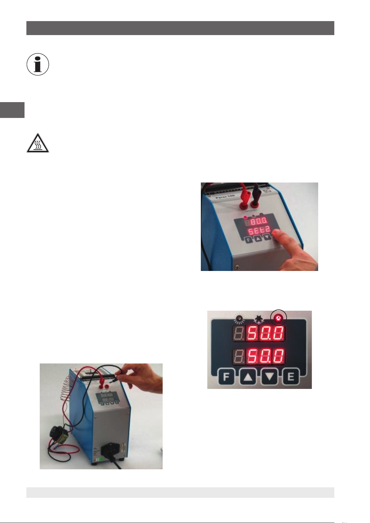
6. Inbetriebnahme, Betrieb
Die Temperaturdifferenz ist proportional zu dem
Durchmesser des Prüflings und dem Durchmesser der Bohrung in der Einsatzhülse.
Die Zeit, die ein Fühler zum Erreichen des
Sollwertes benötigt, ist umso höher, je größer
der Unterschied im Durchmesser zwischen den
DE
6.7.5 Nach der Prüfung oder Kalibrierung
Fühlern und den Bohrungen ist.
WARNUNG!
Verbrennungsgefahr!
Hohe Temperaturen können zu akuten Verbrennungen führen.
Am Ende der Kalibrierung den Temperaturfühler
nicht bei hohen Temperaturen aus dem
Kalibrator herausziehen.
▶
Den Kalibrator inklusive Temperaturfühler
herunterkühlen, sodass ein thermischer
Schock verhindert wird, wie in Kapitel
6.9 „Abkühlen des Metallblockes“ beschrieben.
▶
Bevor der Kalibrator ausgeschaltet wird,
überprüft ob die Temperatur nahezu der
Umgebungstemperatur gleicht.
3. Gerät einschalten.
4. Mit der Taste [▲] oder [▼] den Sollwert eingeben, der
T
entspricht.
min
5. Mit der Taste [E] die Eingabe bestätigen.
6. Mit der Taste [F] die Funktion SEt2 auswählen.
7. Mit der Taste [▲] oder [▼] den Sollwert T
8. Mit der Taste [E] die Eingabe bestätigen.
Die Temperatur des Thermostatschalters sollte sich
⇒
zwischen T
9. Mit der Taste [F] die Funktion Grd (Grad pro Minute)
aufrufen.
10. Mit der Taste [▲] oder [▼] den Wert für die Heizände-
rungsrate eingeben.
Für einen genaueren Test sind niedrige Werte bevor-
⇒
zugt (z. B. Werte von weniger als 1 °C pro Minute).
11. Mit der Taste [E] die Eingabe bestätigen.
min
und T
befinden.
max
eingeben.
max
1. Mit der Taste [▲] oder [▼] die Raumtemperatur eingeben.
2. Mit der Taste [E] die Eingabe bestätigen.
Einsatzhülse nach Verwendung aus dem Kalibrator entnehmen. Feuchte kann zur Bildung von Grünspan auf der
Einsatzhülse im Metallblock führen
In diesem Fall kann die Einsatzhülse stecken bleiben.
⇒
6.8 Schaltertest-Funktion
Mit der Funktion „SCHALTERTEST“ kann die Anfangs- und
Endtemperatur des Thermostats eingestellt werden:
1. Thermostatsensor in eine passende Bohrung der
Einsatzhülse einführen.
2. Thermostat an den Schaltertest-Eingang anschließen.
Die Schaltertest-LED zeigt den Schalterstatus an:
Die LED leuchtet = LED EIN bei geschlossenem Schalter
48 WIKA Betriebsanleitung, Typ CTD4000
14366831.01 05/2020 EN/DE
Page 49

6. Inbetriebnahme, Betrieb
Die LED leuchtet nicht = LED AUS bei geöffneten Schalter
1. Mit der Taste [F] die Funktion run auswählen.
2. Mit der Taste [▲] oder [▼] auf ON einstellen.
Wenn die LED in dieser Funktion blinkt wird damit angezeigt,
dass der Prozess aktiv ist.
■
Durch Eingabe von run OFF wird der Schaltertest
beendet.
6.9 Abkühlen des Metallblockes
WARNUNG!
Verbrennungsgefahr!
Hohe Temperaturen am Metallblock oder am
Temperaturfühler können zu akuten Verbrennungen führen.
▶
Vor dem Transport oder Berühren des Metallblockes und/oder der Kalibriergeräte darauf
achten, dass diese genügend abgekühlt sind.
▶
Um die Kalibriergeräte möglichst schnell von
einer höheren auf eine niedrigere Temperatur zu bringen, die Soll-Temperatur auf eine
niedrigere Temperatur z. B. Raumtemperatur
stellen.
▶
Zur Abkühlung des Metallblocks ist die SollTemperatur auf eine niedrige Temperatur
einzustellen, z. B. Raumtemperatur.
DE
■
Die Auslösewerte des Thermostates sind in den Parametern SOn und SOFF hinterlegt.
■
Die Temperatur variiert zwischen T
Funktion ausgeschaltet wird. Die Werte SOn und SOFF
werden bei jedem Ablauf kontinuierlich aktualisiert.
14366831.01 05/2020 EN/DE
max
und T
min
, bis die
1. Mit der Taste [▲] oder [▼] die Raumtemperatur eingeben.
2. Mit der Taste [E] die Eingabe bestätigen.
Der eingebaute Ventilator schaltet behutsam und automatisch auf eine höhere Geschwindigkeit und liefert somit mehr
Kühlluft.
Nach dem Ausschalten oder nach Entfernen des Netzanschlusses wird durch den
eingebauten Ventilator keine Kühlluft gefördert. Sollte während des Abkühlvorgangs die
Spannungsversorgung unterbrochen werden,
ist trotzdem zwischen dem Metallblock und
dem Gehäuse eine ausreichende thermische
Entkopplung gewährleistet.
49WIKA Betriebsanleitung, Typ CTD4000
Page 50

7. Bedienung des Kalibrators
7. Bedienung des Kalibrators
7.1 Einstellen einer temporären Soll-Temperatur
(Sollwertmodus)
Einstellung der Soll-Temperatur:
■
Drücken der Taste [▲] erhöht den Sollwert.
■
Drücken der Taste [▼] erniedrigt den Sollwert.
■
DE
Mit Taste [E] die Eingabe bestätigen.
Vor jeder Kalibrierung muss gewartet werden, bis sich ein
stabiler Sollwert einstellt.
7.2 Programmierung (Hauptmenü)
In dieser Menüstruktur können sämtliche Einstellungen
vorgenommen werden.
1. Taste [F] drücken.
Es öffnet sich das Hauptmenü.
⇒
2. Mit der Taste [F] den gewünschten Eintrag im Hauptmenü
auswählen (siehe Übersicht).
3. Mit der Taste [E] die Eingabe bestätigen.
7.3 Kurzbeschreibung des Menüs
Der Kalibrator besitzt vier Menüebenen:
■
Erste Menüebene: Allgemeine Einstellungen
■
Zweite Menüebene: Einstellungen zur Optimierung der
Regelung
■
Dritte Menüebene: Rekalibrierung des Gerätes
■
Vierte Menüebene: Einstellungen des Temperaturreglers
50 WIKA Betriebsanleitung, Typ CTD4000
14366831.01 05/2020 EN/DE
Page 51

7. Bedienung des Kalibrators
7.3.1 Menüstruktur, Parameterebenen
LEVEL 1 LEVEL 2
1
TEMPERATURE VALUE
SET POINT
2
or
E
+
F
+
F
NEW VALUE
DE
VALUE
F
F
F
F
F
F
SEt2
VALUE
Grd
VALUE
run
VALUE
SOn
VALUE
SOFF
+
or
or
or
CLOSING THERMOSTAT
TEMPERATURE
(IF CONNECTED)
E
E
E
NEW VALUE
NEW VALUE
NEW VALUE
F
VALUE
F
F
F
F
F
F
+
Pb
VALUE
td
VALUE
ti
VALUE
dEG
VALUE
dEF
VALUE
CodE
F
+
or
or
or
or
or
or
E
E
E
E
E
E
NEW VALUE
NEW VALUE
NEW VALUE
NEW VALUE
NEW VALUE
Code = 2
+
F
LEVEL 3 LEVEL 4
F
F
F
F
Menüstruktur
14366831.01 05/2020 EN/DE
VALUE
Pc
VALUE
SEtH
VALUE
CodE
clt
tbl
or
or
or
E
E
E
NEW VALUE
NEW VALUE
Code = 3
Clearing
Table
VALUE
F
F
F
F
F
tSEt
VALUE
Hy
VALUE
Stby
VALUE
Cod1
VALUE
Cod2
or
or
or
E
E
E
NEW VALUE
NEW VALUE
on / off
51WIKA Betriebsanleitung, Typ CTD4000
Page 52

7. Bedienung des Kalibrators
7.3.2 Erste Menüebene - Allgemeine Einstellungen
▶
Durch Drücken der Taste [F] wird die Menüebene 1 aufgerufen.
▶
Mit der Taste [F] kann durch die Menüfunktionen geblättert werden.
Funktion Bedeutung
SP Sollwert
Einstellung der Soll-Temperatur.
DE
SEt2 Sollwert 2
Grd Gradient
1. Mit der Taste [▲] oder [▼] den Sollwert einstellen.
2. Mit der Taste [E] die Eingabe bestätigen.
Einstellung der Soll-Temperatur 2, die der Kalibrator innerhalb einer Rampe mit einem bestimmten Gradienten
anfahren soll.
1. Mit der Taste [▲] oder [▼] den Sollwert 2 einstellen.
2. Mit der Taste [E] die Eingabe bestätigen.
Der Wert von SEt2 muss immer höher sein als SP.
Heiz- oder Kühländerungsrate beim Wechsel vom Temperaturwert SP zu SEt2 oder SEt2 zu S P.
1. Mit der Taste [▲] oder [▼] den Gradient einstellen.
2. Mit der Taste [E] die Eingabe bestätigen.
Der Gradient muss kleiner als die maximal angegeben Werte in den technischen Spezifikationen
sein (max. 15 °C/min).
run Schaltertest
1. Mit der Taste [▲] oder [▼] ON oder OFF auswählen.
2. Mit der Taste [E] den Schaltertest starten oder stoppen.
Der Temperatur-Blockkalibrator erreicht die Temperatur SP2 ausgehend von SP mit der ausgewählten
Heizänderungsrate. Basis ist die gleiche Temperatur, mit der die Rampe bestätigt wurde. Ist der Wert von SP2
niedriger als der von SP, so übernimmt der Kalibrator den run nicht und das Gerät zeigt „Err“ an. Die LED
blinkt und zeigt damit an, dass die Funktion aktiv ist. Der Sollwert ändert den Wert gemäß der ausgewählten
Änderungsrate. Sobald die Innentemperatur den Sollwert SEt2 erreicht, nimmt die Innentemperatur mit der
Kühländerungsrate ab; der Wert SP wird als der neue Sollwert angesehen. Während des Rampenprogramms
wird der Differentialparameter nicht in Betracht gezogen. Während des Rampenprogramms blinkt die LED
rechts vom Sollwert, und der Sollwert erhöht oder erniedrigt den Wert.
52 WIKA Betriebsanleitung, Typ CTD4000
14366831.01 05/2020 EN/DE
Page 53

7. Bedienung des Kalibrators
Funktion Bedeutung
Beispiel für ein Rampenprogramm
Ein Thermostat mit einem erwarteten Schalterbereich zwischen 120 und 100 °C wird getestet.
SP = 100 °C; SP2 = 120 °C; Gradient = 2 °C/min.
1. Mit den Tasten [▲] oder [▼] SP auf 100 °C einstellen.
2. Mit der Taste [E] die Eingabe bestätigen.
3. Taste [F] drücken.
4. Mit den Tasten [▲] oder [▼] SP2 auf 120 °C einstellen.
5. Mit der Taste [E] die Eingabe bestätigen.
6. Taste [F] drücken.
7. Mit den Tasten [▲] oder [▼] GRD auf 2 °C/min einstellen.
8. Mit der Taste [E] die Eingabe bestätigen.
9. Taste [F] drücken.
10. Mit den Tasten [▲] oder [▼] run auf ON einstellen.
11. Mit der Taste [E] die Eingabe bestätigen.
Nach Bestätigung des Rampenstarts mit der Taste [E] steigt die Ofentemperatur mit der Heizände-
⇒
rungsrate an. Die Temperatur oszilliert ständig zwischen 100 und 120 °C bis run OFF ausgewählt wird.
Natürlich gibt es zu Beginn einige Oszillationen, da die Rampensteigung nicht geeignet ist, aber diese
hören nach kurzer Zeit auf und danach folgt die Ofentemperatur dem Sollwert der Rampe.
SOn Schalter an
Anzeige der Temperatur, an welcher der Temperaturschalter-Kontakt geschlossen ist.
Anzeige der Temperatur, an welcher das Thermostat mit den Klemmen verbunden wurde.
„SCHALTERTEST“ wurde geschlossen.
SOFF Schalter aus
Anzeige der Temperatur, an welcher der Temperaturschalter-Kontakt offen ist.
Anzeige der Temperatur, an welcher das Thermostat mit den Klemmen verbunden wurde.
„SCHALTERTEST“ wurde geöffnet.
Die Werte für SOn und SOFF ändern sich bei jeder Schleife oder jedes Mal, wenn „run OFF“ gewählt wird.
DE
7.3.3 Zweite Menüebene - Einstellungen zur Optimierung der Regelung
▶
Durch gleichzeitiges Drücken der Tasten [F] und [▲] wird die Menüebene 2 aufgerufen.
▶
Mit der Taste [F] kann durch die Menüfunktionen geblättert werden.
▶
Durch gleichzeitiges Drücken von [F] und [▲] oder 20 Sekunden langes Warten Rücksprung zum Hauptmenü.
Funktion Bedeutung
Pb Wert für das Proportionalband in Prozent vom Endwert.
1. Mit der Taste [▲] oder [▼] das Proportionalband in Prozent einstellen.
2. Mit der Taste [E] die Eingabe bestätigen.
Proportionalband bedeutet die Zeitdauer im Messfeld, innerhalb dessen sich der Ausgangsalarm des
Regulierungsfühlers und somit die Leistung des Heizelements ändert.
td Differentialzeit (Derivative time) in Sekunden
1. Mit der Taste [▲] oder [▼] die Differentialzeit in Sekunden einstellen.
2. Mit der Taste [E] die Eingabe bestätigen.
Bei einer stufenweise Änderung der Temperatur wird durch den Differentialanteil eine größere Anpassung des
Anfangswertes hervorgerufen, wodurch der Ofen eine größere Leistung besitzt als er normalerweise aufgrund
des Proportional- und Integralanteils allein haben würde. Da der Fehler weiterhin besteht, wird durch den
Differentialanteil der Einfluss verringert, wodurch der Integralanteil die Aufgabe hat, den Fehler zu beseitigen.
14366831.01 05/2020 EN/DE
53WIKA Betriebsanleitung, Typ CTD4000
Page 54

7. Bedienung des Kalibrators
Funktion Bedeutung
ti Integralzeit (Integral time) in Sekunden
1. Mit der Taste [▲] oder [▼] den Integralanteil in Sekunden einstellen.
2. Mit der Taste [E] die Eingabe bestätigen.
Durch den Integralanteil wird der Fehler zwischen dem gewählten Sollwert und der vom Proportionalanteil
DE
dEG Auswahl der Einheit, in welcher die Temperatur auf dem Display angezeigt werden soll.
dEF Werkseinstellung (Default-Parameter)
allein erreichten Temperatur aufgehoben. Integralzeit bedeutet die Zeitdauer, die der Integralanteil benötigt,
um den Proportionalanteil zu verdoppeln, wobei die Standardparameter beibehalten werden.
1. Mit der Taste [▲] oder [▼] Die Einheit auswählen.
Zur Auswahl stehen °C und °F
⇒
2. Mit der Taste [E] die Einheit übernehmen.
Der Regler kann mit den Werkseinstellung oder kundenspezifischen Regelparametern für P.B./T.I./T.D. betrie-
ben werden.
■
OFF = Kundenspezifische Reglerparameter
■
ON = Werkseinstellung
Der Regler ist von Haus aus schon bestens adaptiert. Bei Änderungswünschen bitte direkt WIKA
kontaktieren.
Durch Auswahl des Parameters „OFF“ und Bestätigung mit der Taste [E] können die Einstellparameter
geändert werden, was auch dann weiterhin funktioniert, wenn der Kalibrator ausgeschaltet wird. Durch
Auswahl des Parameters „ON“ (mit anschließender Bestätigung mit der Taste [E]) werden die Einstellwerte
auf die vom Hersteller festgelegten Werkseinstellungen gesetzt, wodurch diese nicht mehr geändert werden
können. Beim Ausschalten des Kalibrators wird der Parameter auf OFF eingestellt, die Werkseinstellungen
werden jedoch beibehalten.
CodE Zugangscode für die Funktionen in der dritten Menüebene (Voreinstellung = 2)
1. Mit der Taste [▲] oder [▼] das Passwort eingeben (Voreinstellung = 2).
2. Gleichzeitig die Tasten [F] und [▲] drücken.
Dritte Menüebene wird aufgerufen.
⇒
Den Zugangscode wird in der vierten Menüebenen im Parameter „Cod1“ über die serielle Schnittstelle geändert.
Bei Verlust des Zugangscodes kann dieser über das Register 13 ausgelesen werden.
7.3.4 Dritte Menüebene - Rekalibrierung des Gerätes
▶
Über die zweite Menüebene und der Funktion „CodE“ gelangt man in die dritte Menüebene.
▶
Mit der Taste [F] kann durch die Menüfunktionen geblättert werden.
▶
Durch gleichzeitiges Drücken von [F] und [▲] oder 20 Sekunden langes Warten Rücksprung zum Hauptmenü.
Funktion Bedeutung
Pc Kalibrierpunkt
1. Mit der Taste [▲] oder [▼] den mit dem Normalthermometer abgelesenen Wert einstellen.
2. Mit der Taste [E] die Eingabe bestätigen.
SetH Maximale Temperatureinstellung des Sollwertes
(nicht einstellbar)
54 WIKA Betriebsanleitung, Typ CTD4000
14366831.01 05/2020 EN/DE
Page 55

7. Bedienung des Kalibrators
Funktion Bedeutung
CodE Zugangscode für die Funktionen in der vierte Menüebene (Voreinstellung = 3)
1. Mit der Taste [▲] oder [▼] das Passwort eingeben (Voreinstellung = 3).
2. Gleichzeitig die Tasten [F] und [▲] drücken.
Vierte Menüebene wird aufgerufen.
⇒
Den Zugangscode wird in der vierten Menüebenen im Parameter „Cod2“ über die serielle Schnittstelle geändert.
Bei Verlust des Zugangscodes kann dieser über das Register 20 ausgelesen werden.
Tbl Löschen der Kalibriertabelle
In der Anzeige steht Clr.
▶
Mit der Taste [E] die in der Funktion Pc eingegebenen Kalibrierpunkte löschen.
7.3.5 Vierte Menüebene - Einstellungen des Temperaturreglers
▶
Über die dritte Menüebene und der Funktion „CodE“ gelangt man in die vierte Menüebene.
▶
Mit der Taste [F] kann durch die Menüfunktionen geblättert werden.
▶
Durch gleichzeitiges Drücken von [F] und [▲] oder 20 Sekunden langes Warten Rücksprung zum Hauptmenü.
Funktion Bedeutung
tSET Sollwert des Temperaturreglers
1. Mit der Taste [▲] oder [▼] den Sollwert einstellen.
2. Mit der Taste [E] die Eingabe bestätigen.
Der Wert ist vom Hersteller voreingestellt.
DE
Hy Hysterese des Temperaturreglers
1. Mit der Taste [▲] oder [▼] die Hysterese einstellen.
2. Mit der Taste [E] die Eingabe bestätigen.
Der Wert ist vom Hersteller voreingestellt.
Stby Anfangswartezeit
Wird bei der Inbetriebnahme der Wert „OFF“ eingestellt, so wird im Kalibrator sofort der nach dem
Ausschalten ausgewählte letzte Sollwert aufgerufen. Wird bei der Inbetriebnahme der Wert „ON“ eingestellt, so geht der Kalibrator in die Wartestellung und SP blinkt. Um den Kalibrator aus der Wartestellung
zu verschieben und den gewünschten Sollwert einzustellen, muss eine beliebige Taste gedrückt werden.
Cod1 Zugangscode für dritte Menüebene
(Voreinstellung = 2)
Cod1 kann nur über die serielle Schnittstelle geändert werden.
Cod2 Zugangscode für vierte Menüebene
(Voreinstellung = 3)
Cod2 kann nur über die serielle Schnittstelle geändert werden.
14366831.01 05/2020 EN/DE
55WIKA Betriebsanleitung, Typ CTD4000
Page 56

8. Serielle Kommunikation
8. Serielle Kommunikation
An der Vorderseite des Kalibrators befindet sich eine 9-polige
Buchse, die an den Temperaturregler angeschlossen ist und
mit der der Kalibrator mit einem PC (siehe Abbildung) über
den RS-232-Eingang vollständig gesteuert werden kann.
DE
4
21
6
5
3
7
8 9
Rx
Tx
Anschlussbelegung, Ansicht von vorne
Der externe PC muss der Norm IEC 950 entsprechen.
▶
Nach dem Einschalten des Kalibrators und Anschließen
der seriellen Schnittstelle warten, bis das System hochgefahren ist.
▶
Zur Aktivierung der seriellen Kommunikation an der Anzeige die Taste [E] drücken.
Allgemeine Kenngrößen
Baudrate 9600
N. Bit 8
Parität Nein
Stoppbit 1
Die Kommunikation erfolgt in Halb-Duplex-Form, das heißt,
dass Senden und Empfangen nicht gleichzeitig stattfinden
können.
Der Regler antwortet nur auf einen Befehl; er antwortet nie
selbst.
Der Befehl und die Antwort sind eine ASCII-Zeichenkette,
wie vorstehend angegeben. Das Kommunikationsprogramm
kann ASCII in Dezimal umwandeln und daraus Zahlenwerte
extrahieren. Die Standardadresse ist 1.
8.1 Liste der Variablen und Parameter
Variable Bezeichnung Parameter
Einstellbar Lesbar
6 Integralzeit in Sekunden xxx
7 Differentialzeit in
Sekunden
10 Einheiten 0 = °C
13 Cod1 (Zugangsschlüs-
sel)
2 = Voreingestellt
14 Baudrate
9600 (Voreingestellt)
15 Adresse
16 Seriennummer
19 Mindestsollwert -
20 Cod2
3 = Voreingestellt
21 Warten ON
22 Einschalttemperatur -
23 Ausschalttemperatur -
24 Firmware-Version -
27 Interner Sensortyp - 0 = Pt100
28 Stabilitätsbereich -
29 Stabilitätssymbol - 0 = nein
31 Alarmeinstellung -
33 Offset der Umgebungs-
temperatur
xxx
1 = °F
- 2400
- 3
OFF
-
0 = °C
1 = °F
4800
9600
19200
2 = Typ K
1 = ja
Jeder Befehl besteht aus einer ASCII-Zeichenkettenfolge.
Zuerst kommt das Zeichen $; das nächste gibt die Geräteadresse an (Voreinstellung 1) und dann folgt der Befehl (4
Zeichen).
Möglichkeit
RVAR = Lesen der Daten
WVAR = Schreiben der Daten
Variable Bezeichnung Parameter
Einstellbar Lesbar
0 Sollwert x ... 9999
1 Rampe 1 = Ein
0 = Aus
2 Sollwert 2 x ... 9999
3 Gradient x ... 9999
5 Proportionalband 0 ... 100 %
1 = Ein
0 = Aus
Der letzte Teil der Zeichenkette ist abhängig von der Art des
Befehls. Mit dem Zeichen <cr> endet die Zeichenfolge.
56 WIKA Betriebsanleitung, Typ CTD4000
14366831.01 05/2020 EN/DE
Page 57

8. Serielle Kommunikation
8.2 Lesen der Daten
Zum Lesen den Befehl RVAR verwenden.
Beispiel:
Lesen des aktuellen Sollwertes (Variable 0):
Die Befehlszeichenkette lautet: $1RVAR0_<cr>
Bedeutung der Befehlszeichenkette
$ = Anfang der Nachricht
1 = Geräte-Adresse
RVAR = Lesebefehl
0 = Die Nummer der zu lesenden Variablen (siehe
Tabelle)
_ = Leerzeichen
<cr> = Ende der Nachricht
Antwort (Beispiel für 110,0 °C/°F)
Die Antwort der Zeichenkette lautet: *1_110.0
Mit dem Zeichen <cr> endet die Nachricht.
Bedeutung der Antwortzeichenkette
* = Anfang der Antwort
1 = Geräte-Adresse
_ = Leerzeichen
110.0 = Numerischer Wert von Daten mit dem Zeichen
[.] um den Dezimalteil der Zahl zu trennen
<cr> = Ende der Nachricht
Die Antwort enthält nicht die Einheit. Zum Lesen der Einheit
muss die Variable 10 gelesen werden:
Die Befehlszeichenkette lautet: $1RVAR10_<cr>
Die Antwort der Zeichenkette lautet: *1_0 für °C
Die Antwort der Zeichenkette lautet: *1_1 für °F
Bei Erhalt des Befehls lautet die Antwort des Gerätes: *1<cr>
Die Zeichenkette zeigt die Befehlserkennung.
Falls die Einheit der Temperatur nicht °C ist,
muss zuerst die Variable 10 für „Einheiten“ auf
„0“ eingestellt werden.
Die Befehlszeichenkette hierfür lautet: $1WVAR10_0<cr>
Ganze Zahlen als Variablen
Es wurde gerade gezeigt, wie Float-Daten geschrieben
werden.
Die Variablen 1, 10 besitzen zwei oder mehr Zustände (z. B.
die Einheiten) und zu ihrer Aktivierung muss diesen Variable
die entsprechende Zahl zugewiesen werden, die der Einstellung gemäß der nachstehenden Tabelle entspricht:
Variable Bezeichnung Parameter
1 Rampe 1 = ON 0 = OFF
10 Einheiten 0 = °C 1 = °F
Beispiel
Die Variable 1 entspricht der Aktivierung der Rampe. Soll
sie zwecks Aktivierung der Rampe auf ON gestellt werden,
so muss der Wert 0 und ansonsten der Wert 1 zugewiesen
werden.
Die Befehlszeichenkette lautet: $1WVAR1_1<cr>
Bei den anderen Variablen analog vorgehen.
DE
8.3 Schreiben der Daten (FLOAT-VARIABLEN)
Zum Lesen den Befehl WVAR verwenden.
Beispiel:
Schreiben des Sollwertes auf 132.4 °C (Variable 0):
Falls die Einheit der Temperatur bereits °C ist,
reicht es aus, den Sollwert zu schreiben
Die Befehlszeichenkette lautet: $1WVAR0_132.4<cr>
Bedeutung der Befehlszeichenkette
$ = Anfang der Nachricht
1 = Geräte-Adresse
WVAR = Schreibbefehl
0 = Die Nummer der einstellbaren Variablen (siehe
Tabelle)
_ = Leerzeichen
132.4 = Numerischer Wert von Daten mit dem Zeichen
[.] um den Dezimalteil der Zahl zu trennen
<cr> = Ende der Nachricht
14366831.01 05/2020 EN/DE
57WIKA Betriebsanleitung, Typ CTD4000
Page 58

9. Störungen
9. Störungen
Personal: Fachpersonal
Schutzausrüstung: Schutzhandschuhe
VORSICHT!
Körperverletzungen, Sach- und Umweltschäden
Kontaktdaten siehe Kapitel 1 „Allgemeines“ oder
Rückseite der Betriebsanleitung.
DE
Können Störungen mit Hilfe der aufgeführten
Maßnahmen nicht beseitigt werden, Gerät unverzüglich außer Betrieb setzen.
WARNUNG!
Körperverletzungen, Sach- und Umweltschäden durch hohe Temperaturen
Am Gerät können im Fehlerfall extreme Temperaturen anliegen.
▶
Notwendige Schutzausrüstung tragen.
Fehler Ursachen Maßnahmen
Keine Funktion
Der Kalibrator reagiert bei
angeschlossenem Netzkabel und
angeschaltetem Schalter nicht.
Die Sicherung hat ausgelöst, als
das Gerät eingeschaltet war
Die Spannungsversorgung ist nicht richtig
hergestellt
Die Sicherung ist defekt Sicherung ersetzen
Das Netzkabel ist defekt Netzkabel durch gleichwertiges ersetzen
Der Hauptschalter ist defekt Zur Reparatur einschicken
Falsche Sicherung Überprüfen, ob die richtige Sicherung für die
▶
Kontakt mit dem Hersteller aufnehmen.
▶
Bei notwendiger Rücksendung die Hinweise
unter Kapitel 11.2 „Rücksendung“ beachten.
Die Spannungsversorgung prüfen
Hilfsenergie eingesetzt ist und gegebenenfalls
Sicherung austauschen.
Der Hauptschalter ist defekt Zur Reparatur einschicken
Kurzschluss im Heizelement
Endtemperatur wird nicht erreicht Das Halbleiterrelais oder Heizelement ist defekt Zur Reparatur einschicken
Der Übertemperaturschalter hat ausgelöst
Das Display arbeitet einwandfrei,
die Temperatur steigt jedoch nicht
und der Kalibrator zeigt Fehlercode Ht an.
Das Display arbeitet einwandfrei,
die Temperatur steigt jedoch nicht
und der Kalibrator zeigt nach
wenigen Sekunden Fehlercode
Err an.
Display zeigt anderen Wert an, als
im Block vorhanden
Überschreiten der Temperatur
über den Sollwert
Kalibrator kühlt kaum nach unten abDer Regler ist defekt Zur Reparatur einschicken
Das Sicherheitsthermostat hat aufgrund von
Übertemperatur ausgelöst
Die Heizung ist fehlerhaft Eine beliebige Taste drücken, um zu sehen, ob
Der Temperaturregler ist fehlerhaft Temperaturregler austauschen
Der Innenfühler ist nicht kalibriert Temperatur-Blockkalibrator zur Kalibrierung
Der Regler ist defekt Zur Reparatur einschicken
Die Steuerplatine ist defekt Zur Reparatur einschicken
Der Lüfter ist defekt
Sollwert Set des Sicherheitsthermostaten
überprüfen: Siehe Menüebene 4.
die Heizung wiederhergestellt werden kann.
Zur Reparatur einschicken
einschicken
Auf dem Display erscheint 810
oder 786.
Der Innenfühler ist fehlerhaft Zur Reparatur einschicken
58 WIKA Betriebsanleitung, Typ CTD4000
14366831.01 05/2020 EN/DE
Page 59

10. Wartung, Reinigung und Rekalibrierung
10. Wartung, Reinigung und Rekalibrierung
Personal: Fachpersonal
Schutzausrüstung: Schutzhandschuhe
Kontaktdaten siehe Kapitel 1 „Allgemeines“ oder
Rückseite der Betriebsanleitung.
10.1 Wartung
Das hier beschriebene Gerät ist wartungsfrei.
Reparaturen sind ausschließlich vom Hersteller durchzuführen.
Ausgenommen ist der Austausch der Schmelzsicherung
(siehe Kapitel 4.5 „Sicherung“).
Vor dem Austausch der Schmelzsicherung den
Temperatur-Blockkalibrator durch Ziehen des
Netzkabels aus der Netzsteckdose von der
Netzspannung trennen.
Nur Originalteile verwenden (siehe Kapitel 13 „Zubehör“).
10.2 Reinigung
VORSICHT!
Körperverletzungen, Sach- und Umweltschäden
Eine unsachgemäße Reinigung führt zu Körperverletzungen, Sach- und Umweltschäden.
Messstoffreste im Gerät können zur Gefährdung
von Personen, Umwelt und Einrichtung führen.
▶
Notwendige Schutzausrüstung tragen.
▶
Reinigungsvorgang wie folgt beschrieben
durchführen.
▶
Den Kalibrator nur in kaltem Zustand reinigen.
1. Den Temperatur-Blockkalibrator abkühlen, wie in Kapitel
6.9 „Abkühlen des Metallblockes“ beschrieben.
2. Vor der Reinigung den Temperatur-Blockkalibrator
ausschalten und durch Ziehen des Netzkabels aus der
Netzsteckdose von der Netzspannung trennen.
3. Das Gerät mit einem feuchten Tuch reinigen.
Elektrische Anschlüsse nicht mit Feuchtigkeit in Berührung bringen.
VORSICHT!
Beschädigung des Gerätes
Eine unsachgemäße Reinigung führt zur
Beschädigung des Gerätes!
▶
Keine aggressiven Reinigungsmittel verwenden.
▶
Keine harten und spitzen Gegenstände zur
Reinigung verwenden.
Reinigung von Kalibratoren mit Einsatzhülse
Bei Kalibratoren mit Einsatzhülsen entsteht während des
Betriebes eine geringe Menge Abriebstaub, der Block und
Einsatzhülse verklemmen kann. Um dies zu verhindern,
die Einsatzhülse in regelmäßigen Abständen und vor einer
längeren Außerbetriebnahme des Kalibrators aus dem
Heizblock entfernen. Die Heizblockbohrung mit Druckluft
ausblasen und die Bohrung und Einsatzhülse mit einem
trockenen Tuch reinigen.
Flüssigkeiten oder Öl im Inneren des Blocks
können zur Bildung von Oxiden und Grünspan
auf der Einsatzhülse im Einsatz bei hohen
Temperaturen führen. In diesem Fall könnte die
Einsatzhülse stecken bleiben.
Flüssigkeiten, die in den Kalibrator gelangen,
können Schäden verursachen oder zur Bildung
von giftigen Dämpfen führen.
Reinigung der Lüftergitter
Jeder Kalibrator besitzt am Boden ein engmaschiges Luftgitter, durch das Kühlluft in den Kalibrator gefördert wird. Das
Gitter je nach Luftverunreinigung in regelmäßigen Abständen
durch Absaugen oder Abbürsten reinigen.
Reinigung der Außenseite
Gerät von außen mit einem feuchten Tuch und etwas Wasser
oder mit einem lösungsmittelfreien, leichten Reinigungsmittel
reinigen.
10.3 Rekalibrierung
DKD/DAkkS-Schein - amtliche Bescheinigungen:
Der Temperatur-Blockkalibrator ist vor der Auslieferung mit
Messmitteln, die rückführbar sind auf national anerkannte
Standards, abgeglichen und geprüft.
Auf der Grundlage der DIN ISO 10012 ist der
Temperatur-Blockkalibrator je nach Anwendungsfall in
angemessenen, periodischen Intervallen zu überprüfen.
Es wird empfohlen, das Gerät in regelmäßigen
Zeitabständen von ca. 12 Monaten oder etwa 500
Betriebsstunden durch den Hersteller rekalibrieren zu lassen.
Die Grundeinstellungen werden wenn notwendig korrigiert.
Die Grundlage der Rekalibrierung ist die Richtlinie des
Deutschen Kalibrierdienstes DKD R5-4. Die hier beschriebenen Maßnahmen werden bei der Rekalibrierung angewendet
und berücksichtigt.
DE
4. Gerät säubern, um Personen und Umwelt vor Gefährdung
durch anhaftende Messstoffreste zu schützen.
14366831.01 05/2020 EN/DE
59WIKA Betriebsanleitung, Typ CTD4000
Page 60

10. Wartung, Reinigung und Rekalibrierung
10.3.1 Eigene Kalibrierung des Innenfühlers
Durch die eigene Kalibrierung werden die
Parameter des internen Referenzfühlers neu
bestimmt bzw. verstellt. Die Genauigkeit ist dabei
abhängig von der verwendeten Referenz.
WIKA garantiert dann nicht mehr für die in den
DE
Die Kalibrierung kann direkt an der Tastatur des Gerätes
vorgenommen werden. Die Kalibrierung erfolgt durch Einstellung des Innenfühlers auf einen oder mehrere Punkte des
Bereichs mit einem Normalthermometer.
Eine Kalibrierung ist nur möglich, wenn die Temperatureinheit
auf “°C” eingestellt ist.
Der Zweck einer Rekalibrierung besteht darin, den Fehler
zwischen der angegebenen Temperatur und dem Wert eines
Normalthermometers zu korrigieren.
Technischen Daten angegebenen Genauigkeiten.
Sobald diese Veränderungen durchgeführt werden, verliert auch das aktuelle
Kalibrierzertifikat (falls mitgeliefert) seine Gültigkeit.
Zur Kalibrierung des Innenfühlers muss ein
Normalthermometer mit einer größeren Präzision als der
des Kalibrators zur Verfügung stehen und die nachstehende
Anleitung befolgt werden.
1. Normalthermometer in die geeignetste Bohrung des
Kalibrators einführen.
2. Je nach dem Messbereich des Gerätes oder des Außenbereichs, in dem die Kalibrierung durchgeführt werden
soll, mindestens 5 Kalibrierpunkte oder mehrere Kalibrierpunkte (max. 10 Punkte) festlegen.
3. Den ersten Kalibrierpunkt einstellen und warten, bis der
Kalibrator sich stabilisiert hat (siehe Stabilitäts-LED).
4. Menüebene 3 aufrufen (siehe 7.3.4 „Dritte Menüebene Rekalibrierung des Gerätes“) und PC auswählen.
5. Mit der Taste [▲] oder [▼] den mit dem
Normalthermometer abgelesenen Wert einstellen
6. Mit der Taste [E] die Eingabe bestätigen.
Die Bestätigung wird durch einen Piepton angezeigt.
⇒
7. Schritt 3 ... 6 für die anderen Punkte wiederholen.
8. Nach Beendigung des Vorgangs ca. 20 Sekunden warten
und dann zum Hauptmenü zurückkehren.
Nach Beendigung der Kalibrierung das Normalthermometer
NICHT entfernen, wenn der Kalibrator immer noch eine hohe
Temperatur aufweist. Vorher den Kalibrator abkühlen, solange die Fühler noch eingeführt sind, siehe Kapitel 6.9 „Abkühlen des Metallblockes“.
Typ Mögliche Kalibrierpunkte
CTD4000-140 -15, 0, +50, +100 und +125 °C [5, 32, 122, 212 und 257 °F]
CTD4000-375 50, 120, 190, 260 und 340 °C [122, 248, 374, 500 und 644 °F]
CTD4000-650 100, 200, 300, 400, 500 und 600 °C [212, 392, 572, 752, 932 und 1.112°F]
14366831.01 05/2020 EN/DE
60 WIKA Betriebsanleitung, Typ CTD4000
Page 61

11. Demontage, Rücksendung und Entsorgung
11. Demontage, Rücksendung und Entsorgung
Personal: Fachpersonal
Schutzausrüstung: Schutzhandschuhe
WARNUNG!
Körperverletzungen, Sach- und Umweltschäden durch Messstoffreste
Messstoffreste am oder im Gerät können zur
Gefährdung von Personen, Umwelt und Einrichtung führen.
▶
Notwendige Schutzausrüstung tragen.
▶
Angaben im Sicherheitsdatenblatt für den
entsprechenden Messstoff beachten.
▶
Gerät säubern, um Personen und Umwelt vor
Gefährdung durch anhaftende Messstoffreste
zu schützen.
11.1 Demontage
WARNUNG!
Verbrennungsgefahr
Bei der Demontage besteht Gefahr durch hohe
Temperaturen.
▶
Vor der Demontage das Gerät ausreichend
abkühlen lassen!
▶
Zur Abkühlung des Metallblocks ist die SollTemperatur auf eine niedrige Temperatur
einzustellen, z. B. Raumtemperatur.
GEFAHR!
Lebensgefahr durch elektrischen Strom
Bei Berührung mit spannungsführenden Teilen
besteht unmittelbare Lebensgefahr.
▶
Die Demontage des Gerätes darf nur durch
Fachpersonal erfolgen.
▶
Prüf-/und Kalibrieraufbauten im stromlosen
Zustand demontieren.
11.2 Rücksendung
Beim Versand des Gerätes unbedingt beachten:
Alle an WIKA gelieferten Geräte müssen frei von
Gefahrstoffen (Säuren, Laugen, Lösungen, etc.) sein und
sind daher vor der Rücksendung zu reinigen, siehe Kapitel
10.2 „Reinigung“.
Zur Rücksendung des Gerätes die Originalverpackung oder
eine geeignete Transportverpackung verwenden.
Um Schäden zu vermeiden:
1. Das Gerät in eine antistatische Plastikfolie einhüllen.
2. Das Gerät mit dem Dämmmaterial in der Verpackung
platzieren. Zu allen Seiten der Transportverpackung
gleichmäßig dämmen.
3. Wenn möglich einen Beutel mit Trocknungsmittel der
Verpackung beifügen.
4. Sendung als Transport eines hochempfindlichen Messge-
rätes kennzeichnen.
Hinweise zur Rücksendung befinden sich
in der Rubrik „Service“ auf unserer lokalen
Internetseite.
11.3 Entsorgung
Durch falsche Entsorgung können Gefahren für die Umwelt
entstehen.
Gerätekomponenten und Verpackungsmaterialien entsprechend den landesspezifischen Abfallbehandlungs- und
Entsorgungsvorschriften umweltgerecht entsorgen.
Nicht mit dem Hausmüll entsorgen. Für eine
geordnete Entsorgung gemäß nationaler Vorgaben sorgen.
DE
1. Den Temperatur-Blockkalibrator abkühlen, wie in Kapitel
6.9 „Abkühlen des Metallblockes“ beschrieben.
2. Temperatur-Blockkalibrator ausschalten und Netzstecker
aus der Netzsteckdose ziehen.
Nach dem Ausschalten oder nach Entfernen
des Netzanschlusses wird durch den eingebauten Lüfter keine Kühlluft mehr gefördert.
Sollte während des Abkühlvorgangs die
Spannungsversorgung unterbrochen werden,
ist trotzdem zwischen dem Metallblock und
dem Gehäuse eine ausreichende thermische
Entkopplung gewährleistet.
14366831.01 05/2020 EN/DE
61WIKA Betriebsanleitung, Typ CTD4000
Page 62

12. Technische Daten
12. Technische Daten
Technische Daten Typ CTD4000-140
Anzeige
Temperaturbereich -24 ... +140 °C [-11 ... +284 °F]
Genauigkeit
DE
Stabilität
Auösung 0,1 °C
Temperierung
Aufheizzeit ca. 20 min von 20 auf 120 °C
Abkühlzeit ca. 17 min von +20 auf -20 °C
Stabilisierungszeit
Einsatzhülse
Eintauchtiefe 104 mm [4,09 in]
Abmessungen der Einsatzhülse Ø 19 x 104 mm [Ø 0,75 x 4,09 in]
Hülsenwerksto Aluminium
Spannungsversorgung
Betriebsspannung AC 100 ... 240 V ±10 %, 50/60 Hz
Leistungsaufnahme 80 W
Sicherung Träge Sicherung 2,5 A
Netzkabel AC 230 V; für Europa
Kommunikation
Schnittstelle RS-232
Gehäuse
Abmessungen (B x T x H) 130 x 260 x 280 mm [5,12 x 10,24 x 11,02 in]
Gewicht 4,9 kg [10,81 lbs]
1) Ist definiert als Messabweichung zwischen dem Messwert und dem Referenzwert.
2) Maximaler Temperaturunterschied an einer stabilen Temperatur über 30 Minuten.
3) Zeit, um einen stabilen Wert zu erreichen.
1)
2)
3)
0,25 K bei 100 °C [212 °F]
±0,1 K
[von 68 °F auf 248 °F]
[von +68 °F auf -4 °F]
abhängig von Temperatur und Temperaturfühler
Die Messunsicherheit ist definiert als die gesamte Messunsicherheit (k = 2), welche folgende Anteile beinhaltet: Genauigkeit,
Messunsicherheit der Referenz, Stabilität und Homogenität.
62 WIKA Betriebsanleitung, Typ CTD4000
14366831.01 05/2020 EN/DE
Page 63

12. Technische Daten
Technische Daten Typ CTD4000-375 Typ CTD4000-650
Anzeige
Temperaturbereich t
Genauigkeit
Stabilität
Auösung 0,1 °C
Temperierung
Aufheizzeit ca. 20 min von 30 auf 375 °C
Abkühlzeit ca. 40 min von 375 auf 100 °C
Stabilisierungszeit
Einsatzhülse
Eintauchtiefe 150 mm [5,91 in]
Abmessungen der Einsatzhülse Ø 26 x 150 mm [Ø 1,02 x 5,91 in]
Hülsenwerksto Aluminium Messing, vernickelt
Spannungsversorgung
Betriebsspannung AC 115/230 V ±10 %, 50/60 Hz
Leistungsaufnahme 600 W
Sicherung Träge Sicherung 6,3 A (bei AC 115 V)
Netzkabel AC 230 V; für Europa
Kommunikation
Schnittstelle RS-232
Gehäuse
Abmessungen (B x T x H) 130 x 260 x 280 mm [5,12 x 10,24 x 11,02 in]
Gewicht 5,4 kg [11,9 lbs] 6 kg [13,2 lbs]
1) Ist definiert als Messabweichung zwischen dem Messwert und dem Referenzwert.
2) Maximaler Temperaturunterschied an einer stabilen Temperatur über 30 Minuten.
3) Zeit, um einen stabilen Wert zu erreichen.
1)
2)
3)
+ 15 °C ... 375 °C [t
amb
0,35 K 0,5 K
±0,1 K ±0,3 K
[von 86 °F auf 707 °F]
[von 707 °F auf 212 °F]
abhängig von Temperatur und Temperaturfühler
Automatisch umschaltbar
Träge Sicherung 3,15 A (bei AC 230 V)
+ 15 °F ... 707 °F] t
amb
+ 15 °C ... 650 °C [t
amb
ca. 35 min von 50 auf 650 °C
[von 122 °F auf 1.202 °F]
ca. 60 min von 650 auf 100 °C
[von 1.202 °F auf 212 °F]
+ 15 °F ... 1.202 °F]
amb
DE
Die Messunsicherheit ist definiert als die gesamte Messunsicherheit (k = 2), welche folgende Anteile beinhaltet: Genauigkeit,
Messunsicherheit der Referenz, Stabilität und Homogenität.
Zertifikate/Zeugnisse
Zertifikat
Kalibrierung
Empfohlener Rekalibrierungszyklus 1 Jahr (abhängig von den Nutzungsbedingungen)
■
Ohne
■
Kalibrierzertifikat 3.1 nach DIN EN 10204
■
DKD/DAkkS-Kalibrierzertifikat
Zulassungen und Zertifikate siehe Internetseite
Weitere technische Daten siehe WIKA Datenblatt CT 41.10 und Bestellunterlagen.
14366831.01 05/2020 EN/DE
63WIKA Betriebsanleitung, Typ CTD4000
Page 64

13. Zubehör
13. Zubehör
Einsatzhülsen für Typ CTD4000-140 Bestellcode
Beschreibung CTA9I-2O
Einsatzhülse ungebohrt
Ø 19 x 104 mm [Ø 0,75 x 4,09 in]
Werkstoff: Aluminium
DE
-N-
Einsatzhülse gebohrt
Ø 19 x 104 mm [Ø 0,75 x 4,09 in]
Bohrtiefe: 100 mm [3.94 in]
Werkstoff: Aluminium
Bohrungsdurchmesser:
1 x 3,3 mm, 1 x 4,8 mm und 2 x 6,4 mm [1 x 0,13 in, 1 x 0,19 in und 2 x 0,25 in]
Hülsenwechselwerkzeug -J-
-W-
Bestellangaben für Ihre Anfrage:
1. Bestellcode: CTA9I-2O
2. Option:
⇓
[ ]
Einsatzhülsen für Typ CTD4000-375 Bestellcode
Beschreibung CTA9I-2P
Einsatzhülse ungebohrt
Ø 26 x 150 mm [Ø 1,02 x 5,91 in]
Werkstoff: Aluminium
Einsatzhülse gebohrt
Ø 26 x 150 mm [Ø 1,02 x 5,91 in]
Bohrtiefe: 145 mm [5,71 in]
Werkstoff: Aluminium
Bohrungsdurchmesser:
1 x 12,7 mm und 1 x 6,4 mm
[1 x 0,50 in und 1 x 0,25 in]
Bohrungsdurchmesser:
1 x 3,2 mm, 1 x 4,8 mm, 1 x 6,4 mm und 1 x 11,1 mm
[1 x 0,13 in, 1 x 0,19 in, 1 x 0,25 in und 1 x 0,44 in]
-N-
-O-
-P-
Hülsenwechselwerkzeug -J-
Bestellangaben für Ihre Anfrage:
1. Bestellcode: CTA9I-2P
2. Option:
⇓
[ ]
64 WIKA Betriebsanleitung, Typ CTD4000
14366831.01 05/2020 EN/DE
Page 65

13. Zubehör
Einsatzhülsen für Typ CTD4000-650 Bestellcode
Beschreibung CTA9I-2Q
Einsatzhülse ungebohrt
Ø 26 x 150 mm [Ø 1,02 x 5,91 in]
Werkstoff: Messing, vernickelt
-N-
Einsatzhülse gebohrt
Ø 26 x 150 mm [Ø 1,02 x 5,91 in]
Bohrtiefe: 145 mm [5,71 in]
Werkstoff: Messing, vernickelt
Bohrungsdurchmesser:
1 x 15,7 mm [0,62 in]
Bohrungsdurchmesser:
1 x 17,5 mm [0,69 in]
Bohrungsdurchmesser:
1 x 6,5 mm und 1 x 12,7 mm
[1 x 0,26 in und 1 x 0,50 in]
Bohrungsdurchmesser:
1 x 4,5 mm, 1 x 6,5 mm und 1 x 10,5 mm
[1 x 0,18 in, 1 x 0,26 in und 1 x 0,41 in]
Bohrungsdurchmesser:
1 x 3,2 mm, 1 x 5 mm, 1 x 6,5 mm und 1 x 9,5 mm
[1 x 0,13 in, 1 x 0,20 in, 1 x 0,26 in und 1 x 0,37 in]
Bohrungsdurchmesser:
1 x 3,2 mm, 1 x 5 mm, 1 x 7 mm und 1 x 9,5 mm
[1 x 0,13 in, 1 x 0,20 in, 1 x 0,28 in und 1 x 0,41 in]
Hülsenwechselwerkzeug -J-
-Q-
-R-
-S-
-T-
-U-
-V-
DE
Bestellangaben für Ihre Anfrage:
1. Bestellcode: CTA9I-2Q
2. Option:
Beschreibung CTX-A-KB
Transportkoffer -CC-
Bestellangaben für Ihre Anfrage:
1. Bestellcode: CTX-A-KB
2. Option:
WIKA-Zubehör finden Sie online unter www.wika.de.
14366831.01 05/2020 EN/DE
⇓
[ ]
Bestellcode
⇓
[ ]
65WIKA Betriebsanleitung, Typ CTD4000
Page 66

DE
66 WIKA Betriebsanleitung, Typ CTD4000
14366831.01 05/2020 EN/DE
Page 67

14366831.01 05/2020 EN/DE
67WIKA operating instructions, model CTD9100-1100
Page 68

WIKA subsidiaries worldwide can be found online at www.wika.com.
WIKA-Niederlassungen weltweit finden Sie online unter www.wika.de.
WIKA Alexander Wiegand SE & Co. KG
Alexander-Wiegand-Straße 30
63911 Klingenberg • Germany
Tel. +49 9372 132-0
Fax +49 9372 132-406
info@wika.de
www.wika.de
14366831.01 05/2020 EN/DE
68
WIKA operating instructions, model CTD4000
 Loading...