

Page 1
Operating Instructions
High-Speed Pressure Transducer
High-Speed Pressure Transducer CPT6140 PN 0019310001F • 10/2018
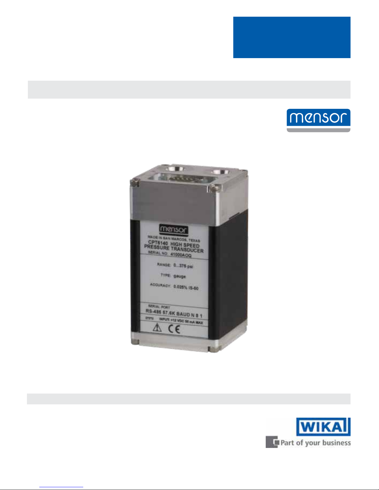
CPT6140
Page 2

2 CPT6140 Operating Instructions
High-Speed Pressure Sensor
CPT6140
This Warning symbol indicates that danger of injury for persons and the
environment and/or considerable damage (mortal danger, danger of injury)
will occur if the respective safety precautions are not taken.
This Caution symbol indicates danger for the system and material if the
respective safety precautions are not taken.
This Notice symbol does not indicate safety notices but information for a
better understanding of the facts.
!
Caution
i
Notice
Warning
!
Page 3

CPT6140 Operating Instructions 3
High-Speed Pressure Sensor
CPT6140
Contents
1. General Information ............................................................... 5
1.1 Warranty .................................................................... 5
1.2 Important Notice .............................................................. 5
1.3 Software License Agreement .................................................... 6
1.4 Mensor Service Plus ........................................................... 6
1.4.1 After the Warranty ......................................................... 6
1.4.2 Calibration Services ....................................................... 6
1.4.3 Certifications and Accreditations ............................................. 6
2. Safety Notices ................................................................... 7
2.1 Warnings and Caution Notices ................................................... 7
3. Product Description ............................................................... 8
3.1 General Description ............................................................ 8
3.2 Power Supply ................................................................ 8
3.3 Sensor ...................................................................... 8
3.4 Circuitry ..................................................................... 8
3.5 Serial In/Out Communications ................................................... 8
4. Specifications ................................................................... 10
5. Installation ..................................................................... 12
5.1 Unpacking .................................................................. 12
5.2 Dimensions ................................................................. 12
5.3 Configuration ................................................................ 12
5.4 Mounting ................................................................... 12
5.5 Pressure Connections ......................................................... 13
5.6 Electrical Connections ......................................................... 13
5.6.1 Connector J1 Wiring ...................................................... 14
5.6.2 RS-232 Operation ........................................................ 14
5.6.3 RS-485 Operation ........................................................ 14
Page 4

4 CPT6140 Operating Instructions
High-Speed Pressure Sensor
CPT6140
6. Operation ...................................................................... 15
6.1 Serial Port Configuration ....................................................... 16
6.2 CPT6140 Address ............................................................ 16
6.3 Communication Output Modes .................................................. 16
6.4 Communication Syntax and Command Conventions ................................. 17
6.4.1 Wildcard Address Operator (*) .............................................. 17
6.4.2 Password Protection ..................................................... 17
6.4.3 Response String Format ................................................... 17
6.4.4 Commands and Queries ................................................... 18
6.4.5 Pressure Unit Code and Conversion ......................................... 20
7. Calibration ..................................................................... 22
7.1 Environment ................................................................ 22
7.2 Equipment .................................................................. 22
7.3 Pressure Standard ............................................................ 24
7.4 Calibration Medium ........................................................... 24
7.5 Calibration Process ........................................................... 24
7.6 Correction Value Query ........................................................ 24
7.7 Zero Adjustment ............................................................. 25
7.7.1 Gauge Zero Offset ....................................................... 25
7.7.2 Absolute Zero Offset ...................................................... 26
7.8 Span Adjustment ............................................................. 27
Page 5

CPT6140 Operating Instructions 5
High-Speed Pressure Sensor
CPT6140
1. General Information
1.1 Warranty
All products manufactured by Mensor are warranted to be free of defects in workmanship and
materials for a period of one year from the date of shipment. No other express warranty is given,
and no armation of Seller, by words or actions, shall constitute a warranty. SELLER DISCLAIMS
ANY IMPLIED WARRANTIES OF MERCHANTABILITY OR FITNESS FOR ANY PARTICULAR
PURPOSES WHATSOEVER. If any defect in workmanship or material should develop under
conditions of normal use and service within the warranty period, repairs will be made at no charge
to the original purchaser, upon delivery of the product(s) to the factory, shipping charges prepaid.
If inspection by Mensor or its authorized representative reveals that the product was damaged by
accident, alteration, misuse, abuse, faulty installation or other causes beyond the control of Men-
sor, this warranty does not apply. The judgment of Mensor will be nal as to all matters concerning
condition of the product, the cause and nature of a defect, and the necessity or manner of repair.
Service, repairs or disassembly of the product in any manner, performed without specic factory
permission, voids this warranty.
MENSOR MAKES NO WARRANTY OF ANY KIND WITH REGARD TO THIS MANUAL, INCLUDING, BUT NOT LIMITED TO, THE IMPLIED WARRANTIES OF MERCHANTABILITY AND FITNESS FOR A PARTICULAR PURPOSE. Mensor shall not be liable for errors contained herein or
for incidental or consequential damages in connection with the furnishing, performance, or use of
this material.
1.2 Important Notice
The product specications and other information contained in this manual are subject to change
without notice.
Mensor has made a concerted eort to provide complete and current information for the proper use
of the equipment. If there are questions regarding this manual or the proper use of the equipment,
contact either Mensor or WIKA:
Mensor WIKA Alexander Wiegand SE & Co. KG
201 Barnes Drive Alexander-Wiegand-Straße 30
San Marcos, TX 78666 D-63911 Klingenberg / Germany
tel: 1-512-396-4200 tel: (+49) 93 72/132-5015
1-800-984-4200 (USA only) website: www.wika.de
website: www.mensor.com fax: (+49) 93 72/132-8767
fax: 1-512-396-1820 email: CTsales@wika.com
email: sales@mensor.com
tech.support@mensor.com
Any reproduction of this manual or parts thereof by any means is prohibited.
Copyright © 2005, Mensor. All rights reserved.
Page 6

6 CPT6140 Operating Instructions
High-Speed Pressure Sensor
CPT6140
1.3 Software License Agreement
This product contains intellectual property, i.e., software programs, that are licensed for use by the
end user/customer (hereinafter “end user”).
This is not a sale of such intellectual property.
The end user shall not copy, disassemble or reverse compile the software program.
THE SOFTWARE PROGRAMS ARE PROVIDED TO THE END USER “AS IS” WITHOUT WARRANTY OF ANY KIND, EITHER EXPRESS OR IMPLIED, INCLUDING, BUT NOT LIMITED TO,
WARRANTIES OF MERCHANTABILITY AND FITNESS FOR A PARTICULAR PURPOSE. THE
ENTIRE RISK OF THE QUALITY AND PERFORMANCE OF THE SOFTWARE PROGRAM IS
WITH THE END USER.
MENSOR AND ITS SUPPLIERS SHALL NOT BE HELD TO ANY LIABILITY FOR ANY DAMAGES
SUFFERED OR INCURRED BY THE END USER (INCLUDING, BUT NOT LIMITED TO, GENERAL, SPECIAL, CONSEQUENTIAL OR INCIDENTAL DAMAGES INCLUDING DAMAGES FOR
LOSS OF BUSINESS PROFITS, BUSINESS INTERRUPTION, LOSS OF BUSINESS INFORMATION AND THE LIKE), ARISING FROM OR IN CONNECTION WITH THE DELIVERY, USE OR
PERFORMANCE OF THE SOFTWARE PROGRAM.
1.4 Mensor Service Plus
If you have problems and you don’t nd the answer in this manual, contact Mensor at
1.800.984.4200 (USA only) or 1.512.396.4200 for personal assistance, or at any of the contact addresses listed on the rear cover of this manual. We are ready to help.
1.4.1 After the Warranty
Mensor’s concern with the performance of this instrument is not limited to the warranty period. We
provide complete repair, calibration and certication services after the warranty for a nominal fee.
1.4.2 Calibration Services
In addition to servicing our own products Mensor can perform a complete pressure calibration
service, up to 20,000 psi, for all of your pressure instruments. This service includes an accredited
calibration.
1.4.3 Certications and Accreditations
Mensor is registered to ISO 9001:2008. The calibration program at Mensor is accredited by A2LA,
as complying with both the ISO/IEC 17025:2005 and the ANSI/NCSL Z540-1-1994 standards.
Page 7
CPT6140 Operating Instructions 7
High-Speed Pressure Sensor
CPT6140
2. Safety Notices
2.1 Warnings and Caution Notices
Not explosion proof. Installation of this instrument in an area requiring
devices rated as intrinsically safe is not recommended.
Some ranges require clean, dry, non-corrosive pressure media. See “Media
Compatibility” in the Specications section of this manual. This instrument
is not designed for oxygen use.
Caution: ESD PROTECTION REQUIRED. The proper use of grounded work
surfaces and personal wrist straps are required when coming into contact
with exposed circuits (printed circuit boards) to prevent static discharge to
sensitive electronic components.
Avoid excessive overpressure to the transducer. Externally mounted relief
valves to provide overpressure protection are available from Mensor as
optional devices and are highly recommended for very low pressure transducers.
Warning
!
!
Caution
!
Caution
Page 8
8 CPT6140 Operating Instructions
High-Speed Pressure Sensor
CPT6140
3. Product Description
3.1 General Description
The CPT6140 High-Speed Pressure Transducer is a self-contained pressure sensing device that
provides high accuracy pressure measurements. The CPT6140 gives a streaming output at 250Hz
from a low hysteresis silicon sensor with electronically compensated pressure linearity over the
specied temperature range. Communication with the CPT6140 is over a RS-232 or RS-485 serial
bus.
3.2 Power Supply
The required 12VDC power enters via J1. The power supply used to power the device must be a
limited-energy device supplying less than 8.3A at 12VDC. It is recommended that the power supply
is IEC 61010-1 3rd ed. compliant.
3.3 Sensor
The pressure sensor is a micromachined silicon strain gauge. The sensor is secured to the transducer case.
3.4 Circuitry
All of the circuitry is included on a single PC board. The combined pressure and temperature sensor signals are routed to the signal conditioning electronics.
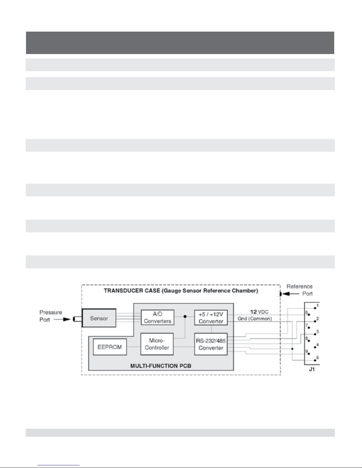
3.5 Serial In/Out Communications
Figure 3.6 - Serial In/Out Communications
Page 9

CPT6140 Operating Instructions 9
High-Speed Pressure Sensor
CPT6140
The serial bus is set to either RS-232 or RS-485 at the factory. The bus is a two way communication
path used to receive commands and return measured pressure values and other transducer information to the user. This port is also used to transmit calibration adjustments and other user func-
tions to the transducer. Pressure units for each transducer are specied by the customer. Wiring
requirements for the serial port are provided in the Installation section and a list of valid commands
and responses (Table 6.5.4) is provided in the operation section.
Page 10

10 CPT6140 Operating Instructions
High-Speed Pressure Sensor
CPT6140
4. Specications
Accuracy specications presented herein are obtained by comparison with primary standards
traceable to the National Institute of Standards and Technology (NIST). These specications are
obtained in accordance with the ISO Guide to the Expression of Uncertainty in Measurement
(GUM). The calibration program at Mensor is accredited by the American Association of Laboratory
Accreditation (A2LA) as complying with both the ISO/IEC 17025:2005 and the ANSI/NCSL Z540-1-
1994 standards.
Mensor reserves the right to change specications without notice.
High-Speed Pressure Transducer Technical Specication
Accuracy
1)
0.025 % FS
2)
0.025 % IS-50
3)
Measuring ranges
Gauge pressure 0 ... ≥ 70 mbar up to 0 ... 400 bar
(0 ... ≥ 1 up to 0 ... 6,000 psi)
4)
0 ... 1 up to 0 ... 400 bar
(0 ... 15 up to 0 ... 6,000 psi)
4)
Bi-directional -35 .... +35 mbar up to -1 ... +400 bar
(-0.5 ... +0.5 up to -14.5 ... +6,000 psi)
4)
-1 ... +10 up to 0 ... 400 bar
(-15 ... +145 psi up to 0 ... 6,000 psi)
4)
Absolute pressure
5)
0 ... 500 mbar up to 0 ... 401 bar abs.
(0 ... 7.5 psi up to 0 ... 6,015 psi abs.)
0 ... 1 up to 0 ... 401 bar abs.
(0 ... 15 up to 0 ... 6,015 psi abs.)
Precision
6)
0.009 % FS 0.009 % FS
Calibration interval 180 days 365 days
CPT6140 as barometric reference
Measuring range 552 ... 1,172 mbar abs. (8 ... 17 psi abs.)
Accuracy
1)
0.025 % of reading
Calibration interval 365 days
Pressure units psi, bar, mbar, Pa, kPa, hPa, MPa, tsi, atm, torr, Dynes/cm², g/cm², kg/cm², mSW, oz/
in², psf, tsf, mmH
2
O (4 °C), cmH2O (4 °C), mH2O (4 °C), inH2O (4 °C), inH2O (20 °C),
inH2O (60 °F), ftH2O (4 °C), ftH2O (20 °C), ftH2O (60 °F), µmHg (0 °C), mmHg (0 °C),
cmHg (0 °C), inHg (0 °C), inHg (60 °F), inSW (0 °C), ftSW (0 °C), mtorr (0 °C)
1) It is dened by the total measurement uncertainty, with the coverage factor (k = 2) and includes the intrinsic performance of the instrument, the measurement
uncertainty of the reference instrument, long-term stability, inuence of ambient conditions, drift and temperature eects over the compensated range with
recommended zero point adjustment every 30 days.
2) FS = full span
3) 0.01 % IS-50 accuracy: Between 0 ... 50 % of the full scale, the accuracy is 0.01% of half of the full scale value and between 50 ... 100 % of the full scale, the
accuracy is 0.01 % of reading.
4) Ranges from 1500 to 2000 psig will be sealed gauge transducers.
5) The minimum calibrated range of absolute transducer(s) is 600mTorr
6) It is dened as the combined eects of linearity, repeatability and hysteresis throughout the stated compensated temperature range
Page 11

CPT6140 Operating Instructions 11
High-Speed Pressure Sensor
CPT6140
High-Speed Pressure Transducer General Specication
Case
Mounting position < 1 bar negligible
Can be adjusted through zero point adjustment (linear shift of the characteristic
curve)
Dimensions See technical drawings
Weight Approximately 17.8 ounces (505 grams)
Display
Resolution > 6 signicant digits
Filter Adjustable exponential lter from 0 ... 99 %
The lter is only active within a dened range of 0.010 % FS.
Warm-up time Approximately 15 min up to the specied accuracy
Connections
Pressure connections Connection 7/16-20 SAE for pressure and reference port
The reference port is sealed for absolute pressure transducers
Overpressure limit 10 % above the nominal pressure of the transducer
Material, wetted parts Aluminium, brass, 316SS, Buna-N, Viton
®
, silicone grease, silicone rubber,
nylon, ceramic, glass, silicon
Voltage supply
Power supply +12 VDC ±10%, 55mA max
Permissible ambient conditions (indoor use only)
Compensated temperature range 15 ... 45 °C (59 ... 113 °F)
Operating temperature range 0 ... 50°C (32 ... 122 °F)
Storage temperature range 0 ... 70 °C (32 ... 158 °F)
Humidity 0 ... 95 % r. h. (non-condensing)
Operating altitude <3048 meters (10,000 ft)
Communication
Interface RS-232 or RS-485
Baud rate 57,600 baud
Measuring rate 250 values/s
Response time 4 ms for a FS pressure pulse
Certicate
Calibration Standard: A2LA calibration certicate
Option: DKD/DAkkS calibration certicate
Approvals and certicates, see website
Page 12

12 CPT6140 Operating Instructions
High-Speed Pressure Sensor
CPT6140
5. Installation
5.1 Unpacking
In addition to functional testing, each unit is inspected for appearance prior to leaving the factory.
Upon receipt, please examine the transducer for shipping damage. Report any apparent damage
to the carrier immediately.
In addition to this manual and password information (les on USB drive), you should have:
• One High-Speed Pressure Transducer
• Any accessories ordered
• An envelope containing a Calibration Certicate
Note: The software utility is downloadable from the Mensor website (see Section 8.2, “Equipment”).
5.2 Dimensions
Mounting holes dimension could vary, slotted mounting holes are recommended.
5.3 Conguration
A typical system will consist of an IBM-PC compatible computer with installed driver software, one
or more CPT6140’s, a DC voltage power supply, and the interconnecting cables. The driver software can be any program congured to operate the appropriate serial interface.
Only 1 CPT6140 can be connected using RS-485. Refer to Figure 5.6.3 for an
illustration of a RS-485 wiring arrangement.
5.4 Mounting
The CPT6140 has mounting holes on the side and back per the drawing in 5.2 Dimensions. The
CPT6140 can be set up in any orientation since the pressure transducer is relatively insensitive to
tilt and vibration. However, excessive motor or machinery vibration of the mounting surface should
be avoided to further ensure stability and accuracy. For the greatest accuracy on transducers with a
full scale range of less than 15 psi, set CPT6140 zero while it is oriented in its operational position.
i
Notice
Page 13

CPT6140 Operating Instructions 13
High-Speed Pressure Sensor
CPT6140
5.5 Pressure Connections
The pressure to be measured is applied to the port labeled P on top of the CPT6140. The reference
connection for gauge pressure is made to the port labeled R. On gauge transducers the reference
port is normally left open to atmosphere. If the transducer is used in a dierential mode, static line
pressures may aect the calibration.
5.6 Electrical Connections
Figure 5.6 - RS-232 Hookup
1. Connectors are female, shown from the wired end.
2. See Table 5.6 for a complete listing of the DB-9 connections.
Table 5.6 - DB-9 Connections
Pin # RS-232 RS-485
1 N.C. TA
2 TX RB
3 RX RA
4 ANA- ANA5 PWR GND PWR GND
6 +12 VDC +12VDC
7 ANA+ ANA+
8 +5Vin +5Vin*
9 N.C. TB
* Use of +5 VDC to power the CPT6140 is not recommended. If required, please consult Mensor for specic
power requirements.
Page 14

14 CPT6140 Operating Instructions
High-Speed Pressure Sensor
CPT6140
5.6.1 Connector J1 Wiring
Power and signals are applied to J1, a 9-pin D-sub male connector. A nominal 12 VDC supply can
be used to power the CPT6140 by applying 12 VDC to pin 6 and ground to pin 5. Power consumption is maximum 55mA at 12 VDC. The CPT6140 is protected against power input reversal. Com-
munication wiring between the host and the CPT6140 is shown in Figures 5.6 and 5.6.3.
5.6.2 RS-232 Operation
For RS-232 serial port operation connect the CPT6140 to the host computer. Notice that the host
TRANSMIT line is connected to the CPT6140 RECEIVE line (TX to RX), and vice versa. One limitation of the RS-232 bus is that a host can support only one instrument.
5.6.3 RS-485 Operation
For RS-485 serial operation, connect the host computer to the CPT6140 per the wire diagram
shown in Figure 5.6.3. Notice that the host TRANSMIT lines are connected to the CPT6140 RECEIVE lines, TA to RA, TB to RB, and so on.
Only one RS-485 CPT6140 should be connected to the system, disregard the wiring to “CPT #31”
and “CPT6140 #2” in the illustrations. Instead, wire the computer directly to the “CPT #1” by the
four-wire method.
Do not connect more than one CPT6140 at a time to the host computer.
Terminating resistor examples are shown and should be determined by the end user when cabling
extremes are required. Resistor values are selected to match the characteristic impedance of the
transmission line, typically 100 to 120 ohms.
Due to the nature of the various RS-485 converters available there may be
communication issues. We have determined that our devices work with
the ACCES I/O PRODUCTS devices. At this time we are not in a position to
comment on any other make of RS-485 converters and their suitability for
use with our products.
!
Caution
!
Caution
Page 15

CPT6140 Operating Instructions 15
High-Speed Pressure Sensor
CPT6140
Figure 5.6.3 - RS-485 Cabling
Note: Multidrop conguration not allowed.
6. Operation
!
Caution
Avoid excessive overpressure to the transducer! Externally mounted
relief valves to provide overpressure protection are available from
Mensor as optional devices, and are highly recommended for very
low pressure transducers.
User programmable exponential ltering is applied to pressure readings in order to minimize
at or near static pressure noise. The lter value can range from 0 (lter OFF) to 99 (maximum ltering). For any positive lter value, the lter is disabled when the pressure change
between consecutive readings is greater than 0.01% full scale. However, each pressure
change of 0.01% FS, or less, between consecutive readings will apply the exponential lter
to the output pressure value to smooth out the readings.
The user can reset the zero and span values via the serial port in order to calibrate the instrument, or the user can change any of several other operating values. The user can also query
the device for its current pressure reading, or to nd the current settings for other parameters.
Page 16

16 CPT6140 Operating Instructions
High-Speed Pressure Sensor
CPT6140
The serial port is set at the factory for either RS-232 or for RS-485 serial operation according to the
customer’s instructions. This section of the manual provides information on the serial port congu-
ration, explains the command conventions used in this manual, and lists the common commands
and queries which are recognized by the CPT6140.
6.1 Serial Port Conguration
Unless otherwise requested by the customer, the CPT6140 serial ports are set at the factory to the
default values listed in the following table.
Table 6.2 - Serial Port Settings
Item Value
Type RS-232
Address 1
Baud 57600
Data Bits 8
Parity None
Stop Bits 1
6.2 CPT6140 Address
Each CPT6140 is assigned address “1” at the factory. In a multiple CPT6140 system each transducer must have a unique address. Valid addresses are 0 through 9 and A through Z (upper and
lower case are interpreted the same). To change an address see Table 6.5.4 for command set
information.
6.3 Communication Output Modes
The output mode is set at the factory to mode 6 on all CPT6140’s.
Mode 6: Burst mode
This is a continuously streaming mode where the pressure value is sent four bytes in IEEE754(big
endian) and a one byte checksum.
Example: 41 E8 A1 CD 97, The rst four bytes received are the characters 41 E8 A1 CD which
decode to 29.079004 in decimal form using IEEE754 conversion process.
Character 97 is the checksum (one byte truncated) from adding the 4 chars above.
Note that the checksum can be used for synchronization of the packets.
Mode 3: Query and response mode
This is an ascii response mode that can be used to read pressure, query stored values and cali
-
brate the CPT6140. See Section 6.5.4 for commands and queries. When a calibration is performed
the CPT6140 must be put into mode 3. All calibration related operations can then be performed
per procedures in Section 8. Once calibration is completed the Save command can be sent. Power
should then be cycled and new values and pressure reading resultant from calibration can be veri-
ed.
Page 17

CPT6140 Operating Instructions 17
High-Speed Pressure Sensor
CPT6140
After calibration is completed the CPT6140 can be put back into the “burst mode” by sending the
mode command with a value of 6. A save must also be sent in order to keep the CPT6140 in mode
6 in case power is cycled.
Note that the CPT6140 can be put into mode 3 and used this way without sending a save com
-
mand. It will revert back to mode 6 if power is cycled (or mode 6 is sent).
i
Notice
The CPT6140 must be in Mode 3 to calibrate. See Section 8 for calibration procedures and the “M<x>” command in table 6.5.4 for the command used to switch
between modes.
6.4 Communication Syntax and Command Conventions
All commands and responses are in ASCII characters; lower and upper case are interpreted the
same. Every command or query begins with the pound symbol (#). The question mark (?) and
decimal point (.) characters are signicant to the CPT6140. All other punctuation characters are
ignored. Some commands require a password string. A carriage return (<cr>) or linefeed (<lf>)
should terminate each command or query.
6.4.1 Wildcard Address Operator (*)
In addition to the 36 unique addresses available, an asterisk (*) functions as a wildcard address
operator. However, this wildcard must not be used in queries if more than one transducer is con
-
nected to a host. The wildcard can be used to address multiple devices with commands.
One use for the wildcard address could be when a CPT6140 is pulled out of a multi-drop setup and
sent to a calibration facility for recertication. The calibration technician can communicate with the
device using the wildcard address without learning or changing its assigned address.
6.4.2 Password Protection
Certain commands require a password to be sent before a setting is changed. The password is
only good for one command, so the password string must be sent immediately before any password protected command string. The form of the password string is described in table 6.5.4. How-
ever, for calibration protection, the actual password has been replaced with PW in the command
string example. See the Password card le for the actual password string to be used in place of PW.
When using 2-wire RS-485 conguration, care should be taken to not append the data string with
both a carriage return <cr> and a linefeed <lf>. Use one terminator or the other, only. When receiv-
ing data from the CPT6140, both a carriage return <cr> and a linefeed <lf> will be sent to terminate
the data string. The linefeed <lf> will always be the last character sent by the CPT6140.
6.4.3 Response String Format
The CPT6140 will return an R to indicate that it has received a command or password rather than
a query. When programming communication with the CPT6140, it is advisable to look for the R
Page 18

18 CPT6140 Operating Instructions
High-Speed Pressure Sensor
CPT6140
response before sending additional commands or queries.
The full command word is shown in Table 6.5.4 in all capital letters. Other conventions used to
describe commands are shown in Table 6.5.3.
Table 6.4.3 - Command Conventions
Convention Description
X Address (single character 0 through 9 or A through Z; case insensitive)
* Wildcard address operator
? Query operator
<sp> Space ( )
PW Password; insert password in place of PW (see le on USB drive; case insensitive)
n One character placeholder for digit or decimal point
n...n Variable length eld
R Ready response
<cr> Carriage return
<lf> Linefeed
6.4.4 Commands and Queries
i
Notice
Each command that changes a parameter is volatile until the SAVE command is issued
Table 6.4.4 - Command Set
Password
Protect
Command
or Query
Command String Return String Description
No ? #X?<cr> X<sp>nnnnnnnnnn<cr>
<lf>
Basic query to return pressure
readings.
No A #XA<sp>n<cr> R Sets address of transducer to
0-9 or A-Z.
No B? #XB?<cr> X<sp>B<sp>n<cr><lf> Returns the turndown, number.
No DC? #XDC?<cr> X<sp>DC<sp>nnnnnn
<cr><lf>
Returns the date of calibration
where nnnnnn is mmddyy.
Ye s DC #XDC<sp>nnnnn
n<cr>
R Loads the date of calibration
where nnnnnn is mmddyy.
No FL? #XFL?<cr> X<sp>FL<sp>nn<cr>
<lf>
Returns the lter – it is the percentage of old reading added
to new reading: 0-99.
Page 19

CPT6140 Operating Instructions 19
High-Speed Pressure Sensor
CPT6140
No FL #XFL<sp>nn<cr> R Sets the lter percentage.
No FS? #XFS?<cr> X<sp>FS<sp>nnnnn<cr>
<lf>
Returns the % FS accuracy.
No ID? #XID?<cr> X<sp>ID<sp>nnMENSOR,
<sp>nnnn61nn,<sp>nnnn
nnnn<sp>Vn.nn<cr><lf>
Returns transducer ID.
No M? #XM?<cr> X<sp>M<sp>Y<cr><lf> Returns mode value.
No M<x> #XM<sp>Y<cr> R Loads the mode integer value
3, or 6 for output mode 3, or
6. See Section 6.3 for mode
descriptions.
N/A PW #XPW<cr> R Disables password protection
for the following single command. See “6.4.2, Password
Protection” for information on
using the password.
No R-? #XR-?<cr> X<sp>R-<sp>n...n
<cr><lf>
Returns minimum range value.
No R+? #XR+?<cr> X<sp>R+<sp>n...n
<cr><lf>
Returns maximum range
value.
No SAVE #XSAVE<cr> R Saves all data to EEPROM for
the current turndown.
No SC? #XSC?<cr> X<sp>SC<sp>n...n
<cr><lf>
Returns a span correction
multiplier.
Ye s SC #XSC<sp>n...
n<cr>
R Loads a span correction
multiplier.
No T? #XT?<cr> X<sp>T<sp>C<cr><lf> Returns cal type.
No U? #XU?<cr> X<sp>n<cr><lf> Returns pressure unit code.
See table 6.4.3.
No ZC? #XZC?<cr> X<sp>ZC<sp>n...n
<cr><lf>
Returns zero correction value
in current units.
Ye s ZC #XZC<sp>n...
n<cr>
R Sets zero correction value in
current units.
Page 20

20 CPT6140 Operating Instructions
High-Speed Pressure Sensor
CPT6140
6.4.5 Pressure Unit Code and Conversion
Table 6.5.5 - Pressure Unit Code and Conversion
Code Unit PSI Conversion Factor
1 psi 1
2 inHg@0°C 2.036020
3
inHg@60°F
2.041772
4 inH2O@4°C 27.68067
5 inH2O@20°C 27.72977
6 inH2O@60°F 27.70759
7 ftH2O@4°C 2.306726
8 ftH2O@20°C 2.310814
9 ftH2O@60°F 2.308966
10 mtorr (@0°C) 51715.08
11 inSW @ 0°C (3.5% salinity) 26.92334
12 ftSW @ 0°C (3.5% salinity) 2.243611
13 atm 0.06804596
14 Bars 0.06894757
15 mBars 68.94757
16 mmH2O@4°C 703.0890
17 cmH2O@4°C 70.30890
18 mH2O@4°C 0.7030890
19 mmHg@0°C 51.71508
20 cmHg@0°C 5.171508
21 Torr 51.71508
22 Kpa 6.894757
23 Pa 6894.757
24 Dynes/cm2 68947.57
25 g/cm2 70.30697
26 kg/cm2 0.07030697
27 mSW @ 0°C (3.5% salinity) 0.6838528
28 oz/in2 16
Page 21

CPT6140 Operating Instructions 21
High-Speed Pressure Sensor
CPT6140
29 psf 144
30 tsf 0.072
31 % Full Scale
32 microns Hg @ 0°C 51715.08
33 tsi 0.0005
35 HPa 68.94757
36 MPa 0.006894757
Page 22

22 CPT6140 Operating Instructions
High-Speed Pressure Sensor
CPT6140
7. Calibration
The CPT6140 transducer automatically adjusts the pressure readings for the eects of temperature
and non-linearity within the calibrated temperature range of 15-45°C. Thus, a calibrated CPT6140
operated within its temperature band, and with proper zero and span settings, will provide accurate
pressure measurements.
The transducer should have the span veried periodically to insure its stability. Initially, the recommended period between calibrations is as specied. This period may be extended as condence is
gained in the span stability.
7.1 Environment
Whenever possible, calibrate the CPT6140 at the same ambient temperature as its normal operating environment. The temperature should be stable, and within the specied calibration range.
In addition, for maximum accuracy, see that the CPT6140 is at rest on a stable platform which is
free of vibration and shock, and oriented similar to its nal installation attitude. At the factory the
CPT6140 is calibrated vertically with the pressure port at the top.
7.2 Equipment
The following equipment is needed to calibrate a gauge transducer (see Figure 8.2):
1. A downloadable version of the most recent calibration utility program. Go to http:\\www.mensor.
com, click “Download”, click “Software”, click “PC software”, then click on Operating & Calibra-
tion software for the series CPT6xxx digital pressure transducers. The calibration utility program
is also available on CD by request.
2. A host computer with a serial port to match the CPT6140 (RS-232 or RS-485), software to run
the CPT6140 transducer, and an appropriate cable.
3. Appropriate pressure and vacuum sources and calibration reference standards for the
CPT6140’s pressure range.
4. Tubing, ttings and valves adequate for the pressure range.
Page 23

CPT6140 Operating Instructions 23
High-Speed Pressure Sensor
CPT6140
A
Figure 8.2 - Calibration Setup
Page 24

24 CPT6140 Operating Instructions
High-Speed Pressure Sensor
CPT6140
7.3 Pressure Standard
Mensor recommends the use of appropriately accurate primary pressure standards when calibrat-
ing this instrument. Such standards should be sucient so that when the techniques of the ISO
Guide to the Expression of Uncertainty in Measurement (GUM) are applied, the instrument meets
its accuracy statements as required by ANSI/NCSL Z540, or other applicable standards. The same
requirement applies to the vacuum gauge used to set the zero oset on absolute calibrations. The
recommended absolute pressure level for setting the zero oset on absolute transducers is be-
tween 600 mTorr absolute and 20% of the active transducer’s span.
7.4 Calibration Medium
The recommended calibration medium for transducers up to 6000 psi is dry nitrogen or clean, dry
instrument air. Hydraulic media (water or oil for example) are recommended for ranges above this
psi. Hydraulic media can be used with lower ranges, however, special techniques must be used in
lling the connection lines and transducer.
7.5 Calibration Process
Please notice that the commands listed in this section are shown in the same style as those in the
Operation section. These are the bare commands seen by the CPT6140, stripped of all program-
ming idioms. Depending on the specic language used to generate them, these commands may
have to be preceded by or enclosed in various symbols for transmission. For this procedure it is
assumed that a single CPT6140 is connected to the host computer, and that its assigned address
is unknown.
The model, serial number, and software version number of the CPT6140 being calibrated can be
obtained by sending: #*ID?<cr>.
7.6 Correction Value Query
The stored correction for zero oset or the span correction factor can be retrieved over the bus. The
returned values have six signicant digits plus a decimal point and a sign. To see the stored values
send either:
#*ZC?<cr> or #*SC?<cr>
These commands may be useful in determining the actual changes in zero and span over time.
Unauthorized alterations of the values can be detected by comparison with previously recorded
correction values.
Each command issued to either calibration parameter must be followed by
the SAVE command to make it permanent. Otherwise, the changes will be
lost the next time the CPT6140 loses power.
Page 25

CPT6140 Operating Instructions 25
High-Speed Pressure Sensor
CPT6140
7.7 Zero Adjustment
To adjust zero, rst determine the correct zero oset, then send the password, and then send the
new zero value. Applying the correct zero pressure and nding the resulting zero oset is dierent
for an absolute transducer than it is for a gauge type unit. Once the zero oset is known, the proce-
dure for sending the zero correction value (which sets the output to zero) is the same for either type
of transducer. When the zero oset is correct, issue a SAVE command to preserve it in non-volatile
memory.
7.7.1 Gauge Zero Oset
Substitute the required password in place of “PW” in the following examples:
1. Determine the current zero oset and make a note of the returned reading.
Next send: #*ZC?<cr>
Record the date and this reading to track zero changes between calibrations.
2. Vent the PRESSURE and REFERENCE ports to atmosphere.
The true pressure is now 0 (zero).
Send: #*PW<cr>
Next send: #*ZC<sp>0<cr>
This will clear the current zero oset from RAM.
3. While vented, determine the current zero pressure reading of the CPT6140.
Send: #*?<cr>
Make a note of the zero value returned by the CPT6140.
4. Subtract the current zero reading from true zero.
The dierence is the new zero oset.
Example: For a 0-30 psi unit with both ports vented:
True Pressure = 0 (vented)
Current Pressure reading (from step 4) = +0.0023 psi
True Pressure – Current Pressure = New Oset
0.0000 (–) +0.0023 = –0.0023 psi oset
5. Enter the new oset into memory.
Send: #*PW<cr>
Next send the zero oset: #*ZC<sp>–.0023<cr>
The new oset of –0.0023 will now be added to all pressure readings of the CPT6140.
Send: #*SAVE<cr> to store the new value in non-volatile memory.
6. To check the zero correction:
Send: #*?<cr>
The reading returned should be 0.0000 psi with both ports vented.
Page 26

26 CPT6140 Operating Instructions
High-Speed Pressure Sensor
CPT6140
7.7.2 Absolute Zero Oset
Substitute the required password in place of “PW” in the following examples:
1. Find the current zero oset and make a note of the returned value.
Send: #*ZC?<cr> and record the reading.
2. Use the setup for absolute pressure shown in Figure 8.2. Apply a stable pressure value between
600 mTorr absolute and 20% of the transducer’s span. Measure the reference pressure reading
in the native units of the CPT6140. This reading becomes the “true pressure”.
3. Clear the current zero oset from RAM.
Send: #*PW<cr>
Next send: #*ZC 0<cr>
4. Determine the current pressure reading.
Send: #*?<cr> and make a note of this reading.
5. Subtract the current pressure reading from the true pressure (vacuum) reading.
The dierence is the zero oset now required.
Example: For a 0-15 psia unit with 600 mTorr absolute pressure applied, using psi units:
600 millitorr = 0.0116 psia (True Pressure)
Current Pressure reading (from step 4) = –0.0011 psia
True Pressure – Current Pressure = New Oset
0.0116 – (–0.0011) = +0.0105 psi oset
6. Enter the new oset into memory.
Send: #*PW<cr>
Then send: #*ZC<sp>.0105<cr>
The new oset of 0.0105 will now be added to all pressure readings.
Send: #*SAVE<cr> to store the new value in non-volatile memory.
7. To check the zero correction:
Send: #*?<cr>
For 600 mTorr the pressure reading returned should be 0.0116 psia.
Page 27

CPT6140 Operating Instructions 27
High-Speed Pressure Sensor
CPT6140
7.8 Span Adjustment
The span adjustment procedure is the same for gauge and absolute units. Always make zero corrections before changing the span factor. A scale factor within the range of 0.9 to 1.1 is used as a
multiplier to correct for span shifts.
1. Determine the current span scale factor and record the reading.
Send: #*SC?<cr>
This reading can be used at some later date to detect a span change between calibrations.
2. To clear the current scale factor:
Send: #*PW<cr>
Next send: #*SC<sp>1<cr>
3. Apply a known true pressure equal to the span of the CPT6140.
To determine the CPT6140 pressure reading:
Send: #*?<cr> and make a note of this reading.
4. Divide the known true pressure by the CPT6140 pressure reading.
The result is the required new span scale factor.
Example: For a 150 psi unit:
True pressure = 150.003 psi
CPT6140 pressure reading (from step 3) = 149.984 psi
True pressure/CPT6140 pressure = New Span Scale Factor
150.003/149.984 = 1.000127
5. To enter the new span scale factor:
Send: #*PW<cr>
Then send: #*SC<sp>1.000127<cr>
Send: #*SAVE<cr> to store the new value in non-volatile memory.
All future pressure readings returned by this CPT6140 will be multiplied by a scale factor of
1.000127 before they are transmitted over the bus.
6. To check the span reading:
Send: #*?<cr>
The returned pressure value should be 150.003 psi, if the pressure has not changed.
Page 28

Mensor
201 Barnes Drive
San Marcos, Tx 78666
Tel: 512-396-4200
Fax: 512-396-1820
sales@mensor.com
www.mensor.com
CPT6140 Operating Instructions PN 0019312001F • 10/2018
WIKA Alexander Wiegand SE & Co. KG
Alexander-Wiegand-Straße 30
D-63911 Klingenberg / Germany
Tel: +49 93 72/132-5015
Fax: +49 93 72/132-8767
CTSales@wika.de
www.wika.de
 Loading...