

Page 1
Precision Pressure Indicator
CPG2500
Operating Instructions
Precision Pressure Indicator CPG2500 PN 0018908001B • 11/2014
Page 2
Precision Pressure Indicator
CPG2500
This Warning symbol indicates that danger of injury for
persons and the environment and/or considerable damage
!
Warning
!
Caution
i
Notice
(mortal danger, danger of injury) will occur if the respective
safety precautions are not taken.
This Caution symbol indicates danger for the system and
material if the respective safety precautions are not taken.
This Notice symbol does not indicate safety notices but
information for a better understanding of the facts.
2 Operating Instructions - CPG2500
Page 3

Precision Pressure Indicator
CPG2500
Table of Contents
1. General Information 7
1.1 Warranty 7
1.2 Important Notice 7
1.3 FCC Radio Frequency Emission Notice 7
1.4 Trademarks and Copyrights 8
1.5 Software License Agreement 8
1.6 Mensor Service Plus 8
1.6.1 After the Warranty 8
1.6.2 Calibration Services 8
1.6.3 Certications and Accreditations 8
1.7 Packaging for Shipment 8
2. Safety Notices 9
2.1 User Responsibilities 9
2.2 General Safety Notices 9
2.3 Warnings and Caution Notices 10
3. General Description 11
3.1 Features 11
3.2 Turning On 12
3.3 Front Panel 12
3.4 Display 13
3.5 Chassis Assembly 13
4. Specications 15
4.1 Transducer Specication 15
4.2 Measurement & General Specications 16
5. Installation 17
5.1 Unpacking the Instrument 17
5.2 Dimensions (inches) 18
5.3 Mounting 19
5.4 Rear Panel 19
5.4.1 Pressure Connections 20
5.4.2 Pressure Port 20
5.4.3 Reference Port 20
5.5 Remote Communication Connections 20
5.6 Power Up 20
Operating Instructions - CPG2500 3
Page 4

Precision Pressure Indicator
CPG2500
6. Local Operation and Setup 21
6.1 General Operation 21
6.1.1 Setup Applications 21
6.1.2 Display Screen Features 21
6.2 Initial Setup 22
6.2.1 Contact and Version Information Application 22
6.2.2 Language Selection 22
6.3 Application Selection and parameter inputs 23
6.4 Applications 24
6.4.1 Measure Application 24
6.4.1.1 Pressure Mode / Emulation Mode 25
6.4.1.2 Auxiliary Displays 25
6.4.1.3 Zero Button 26
6.4.1.4 Tare Button 27
6.4.2 Settings Application 28
6.4.2.1 Languages 28
6.4.2.2 Brightness 29
6.4.2.3 Volume 29
6.4.2.4 User base units / Base units multiplier 30
6.4.2.5 Barometer Units 30
6.4.2.6 Conguration 31
6.4.3 Frames Application 32
6.4.3.1 Frame Format 32
6.4.3.2 Frames Channel 33
6.4.4 Transducer Application 34
6.4.4.1 Transducer Channel Selection 34
6.4.4.2 Transducer Delta Emulation 35
6.4.4.3 Transducer Filter 35
6.4.4.4 Transducer Resolution 36
6.4.4.5 Auxiliary Displays 37
6.4.4.6 Cal Function 38
6.4.5 Remote Application 39
6.4.5.1 Remote Command Set 39
6.4.5.2 Remote Communication Settings 40
6.4.6 Info Application 41
6.4.7 Leak Test Application 42
6.4.8 Troubleshooting Application 43
6.4.9 Service Application 44
6.4.10 Unlocked Service Application 45
4 Operating Instructions - CPG2500
Page 5

Precision Pressure Indicator
CPG2500
7. Remote Operation 47
7.1 Command Set 47
7.2 IEEE-488 47
7.2.1 IEEE-488.2 Commands 47
7.3 Ethernet 48
7.4 Serial 49
7.4.1 Serial Cable Requirements 49
7.5 Mensor Command Set 50
7.6 Command and Query Format 50
7.7 Command Set Denitions 50
7.8 Output Formats 51
7.9 CPG2500 Commands and Queries 51
7.9.1 Units Command Syntax for Measurement Units 56
7.9.2 CPG2500 Error Codes 57
7.9.3 SCPI Commands and Queries 57
7.9.4 SCPI Commands Error Messages and Error Codes 59
7.9.5 GPIB Capability Codes 59
7.9.6 Interface Functions 59
8. Options 61
8.1 Barometer 61
8.2 Barometric Reference 61
8.2.1 Absolute Pressure Emulation 61
8.2.2 Emulation Mode Accuracy 62
8.2.3 Barometric Reference Calibration 62
8.2.4 Barometric reference Specications 62
8.3 Delta Channel 62
8.4 External Transducers (CPT6100 and CPT6180) 62
8.4.1 External Pressure Sensor Connection Cable 62
8.5 External Sensor Package (D-Sub) 63
8.6 Analog Output 63
8.6.1 Specications 63
8.7 Rack Mount Kit 63
8.8 Fittings 63
8.9 Remote Calibration 63
8.9.1 Remote Calibration Kit for Internal Transducers. 64
8.9.2 Barometric Reference Calibration Sled 64
8.9.3 External Calibration Procedures 65
8.9.3.1 Transducer Removal 65
8.9.3.2 Barometric Reference Removal 65
Operating Instructions - CPG2500 5
Page 6

Precision Pressure Indicator
CPG2500
9. Maintenance 67
9.1 Beyond the Warranty 67
9.2 Spare Parts 67
10. Calibration 69
10.1 Environment 69
10.2 Pressure Standards 69
10.3 Media 69
10.4 Setup 70
10.5 Service Application 71
10.5.1 Service Application (unlocked) 72
10.6 Calibration Data 73
10.7 One Point Cal Application 73
10.8 Two Point Cal Application 74
10.9 Linearization 75
10.10 Head Pressure 77
11. Appendix 79
11.1 Conversion Factors, PSI 80
11.2 Conversion Factors, Millitorr 81
11.3 Conversion Factors, Pascal 82
6 Operating Instructions - CPG2500
Page 7

Precision Pressure Indicator
CPG2500
1 General Information
1.1 Warranty
All products manufactured by Mensor are warranted to be free of defects in workmanship and materials for
a period of one year from the date of shipment. No other express warranty is given, and no armation of
Seller, by words or actions, shall constitute a warranty. SELLER DISCLAIMS ANY IMPLIED WARRANTIES
OF MERCHANTABILITY OR FITNESS FOR ANY PARTICULAR PURPOSES WHATSOEVER. If any defect
in workmanship or material should develop under conditions of normal use and service within the warranty
period, repairs will be made at no charge to the original purchaser, upon delivery of the product(s) to the
factory, shipping charges prepaid. If inspection by Mensor or its authorized representative reveals that the
product was damaged by accident, alteration, misuse, abuse, faulty installation or other causes beyond the
control of Mensor, this warranty does not apply. The judgment of Mensor will be nal as to all matters concerning condition of the product, the cause and nature of a defect, and the necessity or manner of repair.
Service, repairs or disassembly of the product in any manner, performed without specic factory permission, voids this warranty.
MENSOR MAKES NO WARRANTY OF ANY KIND WITH REGARD TO THIS MANUAL, INCLUDING,
BUT NOT LIMITED TO, THE IMPLIED WARRANTIES OF MERCHANTABILITY AND FITNESS FOR A
PARTICULAR PURPOSE. Mensor shall not be liable for errors contained herein or for incidental or consequential damages in connection with the furnishing, performance, or use of this material.
1.2 Important Notice
The product specications and other information contained in this manual are subject to change without
notice.
Mensor has made a concerted eort to provide complete and current information for the proper use of
the equipment. If there are questions regarding this manual or the proper use of the equipment, contact
Mensor at:
Mensor WIKA Alexander Wiegand SE & Co. KG
201 Barnes Drive Alexander-Wiegand-Straße 30
San Marcos, Tx 78666 D-63911 Klingenberg / Germany
Tel: 1.512.396.4200 Tel: (+49) 93 72/132-9986
1.800.984.4200 (USA only) web site: www.wika.de
web site: www.mensor.com fax: (+49) 93 72/132-8767
fax: 512.396.1820 e-mail: testequip@wika.de
e-mail: sales@mensor.com
tech.support@mensor.com
1.3 FCC Radio Frequency Emission Notice
This equipment has been tested and found to comply with the limits for a Class A digital device, pursuant
to part 15 of the FCC Rules. These limits are designed to provide reasonable protection against harmful
interference when the equipment is operated in a commercial environment. This equipment generates,
uses, and can radiate radio frequency energy and, if not installed and used in accordance with the instruction manual, may cause harmful interference to radio communications. Operation of this equipment
in a residential area is likely to cause harmful interference in which case the user will be required to correct the interference at his or her own expense.
USE SHIELDED CABLES TO CONNECT EXTERNAL DEVICES TO THIS INSTRUMENT TO MINIMIZE
RF RADIATION.
Operating Instructions - CPG2500 7
Page 8

Precision Pressure Indicator
CPG2500
1.4 Trademarks and Copyrights
Mensor is a registered trademark of Mensor, LP. All other brand and product names are trademarks or
registered trademarks of their respective companies. ©2007, Mensor, LP. All rights reserved.
1.5 Software License Agreement
This product contains intellectual property, i.e., software programs, that are licensed for use by the end
user/customer (hereinafter “end user”).
This is not a sale of such intellectual property.
The end user shall not copy, disassemble or reverse compile the software program.
The software programs are provided to the end user “as is” without warranty
i
Notice
Mensor and its suppliers shall not be held to any liability for any damages suered or incurred by the end
user (including, but not limited to, general, special, consequential or incidental damages including dam-
ages for loss of business prots, business interruption, loss of business information and the like), arising
from or in connection with the delivery, use or performance of the software program.
of any kind, either express or implied, including, but not limited to, warranties
ofmerchantabilityandtnessforaparticularpurpose.Theentireriskofthe
quality and performance of the software program is with the end user.
1.6 Mensor Service Plus
If you have problems and you don’t nd the answer in this manual, contact Mensor at 1.800.984.4200
(USA only) or 1.512.396.4200 for personal assistance, or at any of the contact addresses listed on the
rear cover of this manual. We are ready to help.
1.6.1 After the Warranty
Mensor’s concern with the performance of this instrument is not limited to the warranty period. We pro-
vide complete repair, calibration and certication services after the warranty for a nominal fee.
1.6.2 Calibration Services
In addition to servicing our own products Mensor can perform a complete pressure calibration service,
up to 20,000 psi, for all of your pressure instruments. This service includes an accredited calibration.
1.6.3 CerticationsandAccreditations
Mensor is registered to ISO 9001:2008. The calibration program at Mensor is accredited by A2LA, as
complying with both the ISO/IEC 17025:2005 and the ANSI/NCSL Z540-1-1994 standards.
1.7 Packaging for Shipment
If the product must be shipped to a dierent location or returned to Mensor for any reason through a common carrier it must be packaged properly to minimize the risk of damage.
The recommended method of packing is to place the instrument in a container, surrounded on all sides
with at least four inches of shock attenuation material such as styrofoam peanuts.
8 Operating Instructions - CPG2500
Page 9
Precision Pressure Indicator
CPG2500
2 Safety Notices
2.1 User Responsibilities
To ensure safety, the user must make sure that:
• The system is used properly, no dangerous media are used and that all technical specications are
observed.
• The system is operated in perfect operating condition.
• This operation manual is legible and accessible to the user at the system’s location.
• The system is operated, serviced and repaired only by authorized and qualied personnel.
• The operator receives instruction on industrial safety and environmental protection, and is knowledgeable of the operating instructions and the safety notices contained therein.
2.2 General Safety Notices
The system should only be operated by trained personnel who are familiar with
i
Notice
!
Warning
this manual and the operation of the instrument.
WARNING: A condition for trouble-free and safe operation of this system is proper
transport, proper storage, installation, assembly and proper use as well as careful
operation and maintenance.
Any operation not described in the following instructions should be prohibited.
The system must be handled with care required for an electronic precision instru-
ment(protectfromhumidity,impacts,strongmagneticelds,staticelectricityand
extreme temperatures). Do not insert any objects into the instrument.
The system is powered via the power cable with a voltage that can cause physical injury. Even after disconnecting the system from the power supply, dangerous
voltages can temporarily occur due to capacitance.
Extreme care must be taken with pressure connections when using hazardous or
toxic media.
Repairs must only be performed by authorized service personnel.
i
Notice
Operating Instructions - CPG2500 9
Additional safety notices are found throughout this manual.
Page 10
Precision Pressure Indicator
CPG2500
2.3 Warnings and Caution Notices
WARNING: HIGH PRESSURE! High pressure gases are potentially hazardous.
Energy stored in these gases and liquids can be released suddenly and with
!
Warning
!
Warning
!
Warning
!
Caution
extreme force. High pressure systems should be assembled and operated only by
personnel who have been trained in proper safety practices.
WARNING: NOT EXPLOSION PROOF! Installation of this instrument in an area
requiring devices rated as intrinsically safe is not recommended.
WARNING: POSSIBLE INJURY! The tubing, valves, and other apparatus attached
to the gauge must be adequate for the maximum pressure which will be applied,
otherwise physical injury to the operator or bystanders is possible.
CAUTION: USE THE PROPER PRESSURE MEDIUM! Use only clean, dry, non-corro-
sivegasesunlessotherwisespeciedbyMensor.Thisinstrumentisnotdesigned
for oxygen use.
CAUTION: As with most sensitive electronic equipment, switch the power switch
!
Caution
Additional Warning and Caution notices are found throughout this manual.
obeforeconnectingordisconnectingtoapowersourcetopreventdataloss.Do
notpositiontheequipmentsothatitisdiculttodisconnecttheDCpowerjack.
CAUTION: ESD PROTECTION REQUIRED. The proper use of grounded work
surfaces and personal wrist straps are required when coming into contact with
exposed circuits (printed circuit boards) to prevent static discharge to sensitive
electronic components.
10 Operating Instructions - CPG2500
Page 11
Precision Pressure Indicator
CPG2500
3 General Description
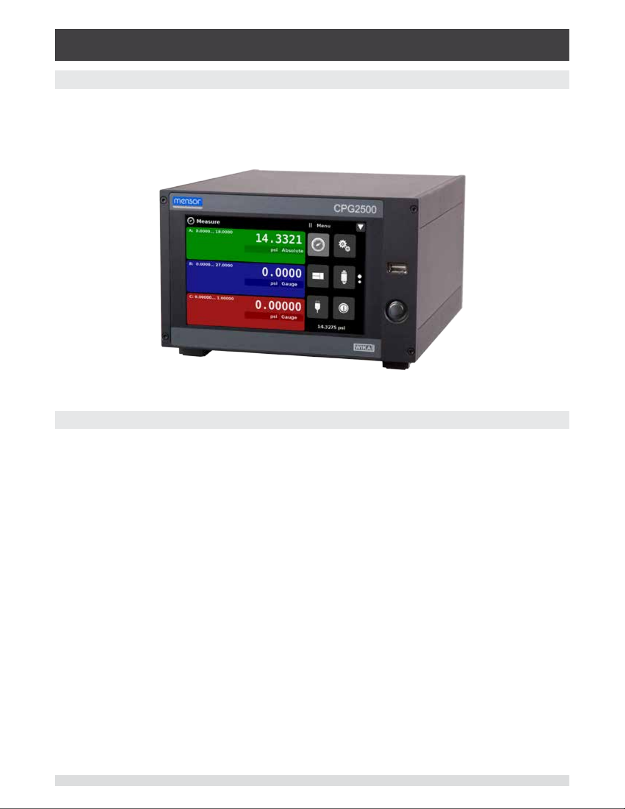
The CPG2500 Precision Pressure Indicator is a multi-channel pressure indicator designed to test and
calibrate a variety of pressure devices in either absolute or gauge pressure modes. The CPG2500 can
have two independent internal transducers, an optional barometric reference and an external remote
pressure transducer.
Figure 3.1 - Desk top version
3.1 Features
Here is a short list of signicant features designed into the CPG2500:
• Up to two removable / interchangeable, highly stable, temperature compensated, internal pressure
transducers. (Option to connect two external transducers via a rear mounted RS-232 port in place of
the two internal transducers)
• An optional remote transducer in addition to the two internal transducers.
• An optional removable / interchangeable internal high accuracy barometric reference transducer
providing gauge pressure emulation for absolute ranges and absolute pressure emulation for gauge
ranges.
• Optional Analog output for each internal sensor.
• 7” Color LCD display with touch screen
• Delta function when two or more transducers are installed
• Multiple languages; change the language for on-screen text and number/date formats by simply
touching one of the “national ag” icons available in the setup screen.
• Desk top or rack mount
• Local Operation, or command and read remotely.
Operating Instructions - CPG2500 11
Page 12
Precision Pressure Indicator
CPG2500
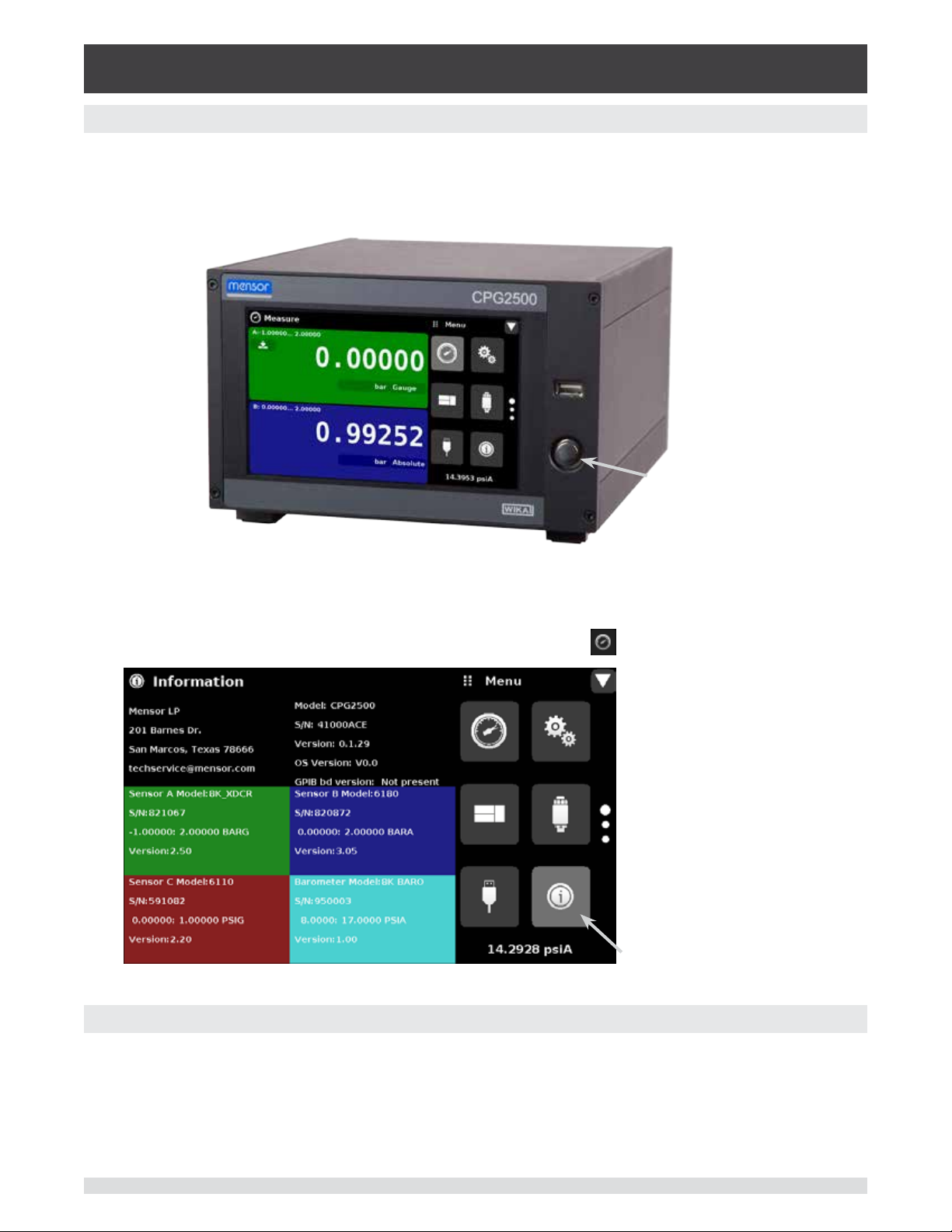
3.2 Turning On
You can conrm that your CPG2500 is operational right now. Apply power to the power connector on
the rear of the instrument with the included power adapter, remove any plastic plugs from the rear panel
pressure ports, and press the power switch to ON. The system will go through an initialization process,
which takes about 45 seconds, and then a display will appear similar to the screen shown below.
Power Switch
ON/OFF
To see information about the conguration of your new CPG2500, touch the Information Application
(App) icon on the menu and a window will appear listing the Mensor customer service contact, model
number and the sensors that are installed. Press the Measure App [
] to return to the main screen.
Information Application
3.3 Front Panel
The CPG2500 front panel includes a 7” color LCD display with touch screen. Operator input is accom-
plished by pressing the words or App icons presented on the display. There is a single discrete on/o
button and a USB on the right hand side. The front panel also shows the model number designation and
brand logos.
12 Operating Instructions - CPG2500
Page 13
Precision Pressure Indicator
CPG2500
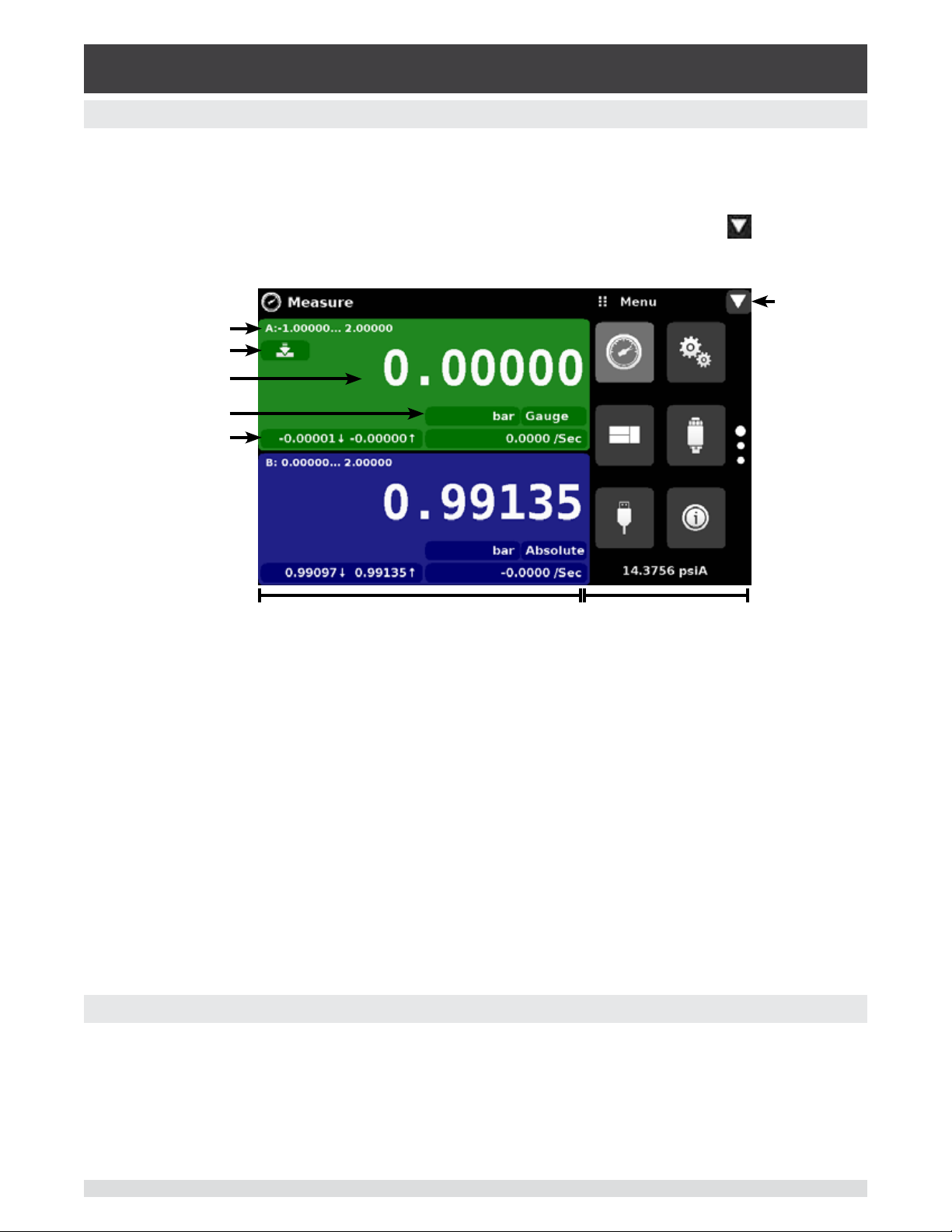
3.4 Display
The display is made up of two sections. In the main screen (“Measure Application”), the left two thirds
shows the transducer channels that are congured for display, along with the pressure reading, units,
mode (absolute or gauge), channel label, an auto zero or tare button (if enabled) and any auxiliary indications that have been chosen. The right one third of the screen has Application Icons (“Apps”) for setting
viewing options, sensor settings, communication settings plus a “Page Down” button [
pressed, shows a second and third page of icons for calibration, remote communication error checking
and a leak test application.
] that, when
Channel label
Page Down
and range
Auto Zero
Reading
Units and Mode
Auxiliary Indications
Transducer Channels Settings Apps
Buttons, Labels and Windows: The CPG2500 touch screen has many buttons with relevant graphic
icons or text which, when pressed, will open a related window where changes can be made or information viewed. Some of these buttons will toggle from one state to another, others present choices or display a numerical data entry screen. Text or icons that are displayed, but do not respond to being touched,
are called labels or windows. Operators will quickly become accustomed to the particular characteristics
of the frequently used buttons.
Main Screen: The main screen or “Measure Application”, appears after power-up. This screen contains
the channel frames and settings button. It will remain as congured after a power cycle.
Transducer Channel Frame(s): The transducer channel frames (left 2/3 of the screen) contain informa-
tion specic to a channel. Up to three channels can be displayed at once, two are shown in the picture
above. The channel frames are color coded with channel A - green, channel B - blue and the remote
channel - red. The optional barometer channel is sky-blue and the delta channel is yellow. If only one
channel is installed, a full frame will be displayed in the color of the channel connected. The channel
frame contains the pressure reading, units, and mode(absolute or gauge) plus any auxiliary displays that
have been chosen.
3.5 Chassis Assembly
The chassis assembly is the housing for the system and the removable transducers. The system has no
user-serviceable parts, and therefore the chassis should not be opened except by qualied repair personnel at Mensor or certied service locations for any reason except to change the removable transduc-
ers.
Operating Instructions - CPG2500 13
Page 14

Precision Pressure Indicator
CPG2500
NOTES
14 Operating Instructions - CPG2500
Page 15

Precision Pressure Indicator
CPG2500
4 Specications
Accuracy specications presented herein are obtained by comparison with primary standards traceable
to a national metrology institute or recognized international standard organization. These specications
are obtained in accordance with the ISO Guide to the Expression of Uncertainty in Measurement (GUM).
The calibration program at Mensor is accredited by the American Association of Laboratory Accreditation
(A2LA) as complying with both the ISO/IEC 17025:2005 and the ANSI/NCSL Z540-1-1994 standards. If
there is an exception to the requirements and recommendations of Z540 during a calibration the excep-
tion is noted on the individual calibration certicate.
Mensor reserves the right to change specications without notice.
4.1 TransducerSpecication
Standard Reference Transducers, Model CPR2550
Accuracy
Gauge Pressure 0 ... .36 to 0 ... <1 psi 0... 1 to 0 ... 10,000 psi 0 ...14.5 to 0 ... 6000 psi
Bi-Directional Pressure -0.18 to 0.18 to >-0.5 ... <0.5 -0.5 ... 0.5 to -15.5 ... 10,000 psi -14.5 ... 145 to -14.5 ... 6000 psi
Absolute Pressure — 0 ... 7.5 to 0 ... 10,000 psia 0 ... 14.5 to 0 ...6015 psia
Calibration Interval 180 days 365 days
Media Compatibility
Metals in contact with media 6000/7000 series Aluminum, 316 SS, brass
Non-metals in contact with media PTFE (Teon®), Urethane, Silicone, RTV, Silicone grease, PVC, Epoxy, Buna-N, uoroelastomers
Sensor
Reading rate 33 readings/second
Calibration adjustments Internal zero adder and span multiplier, up to 11 point linearization for each sensor
(1)
0.03%Full Span 0.01%Full Span 0.01%IS-50
(3)
(Viton®)
365 days
(2)
Premium Reference Transducers, Model CPR2580
Accuracy
Gauge
Pressure
Absolute
Pressure
Calibration
Interval
(1)
0.008% IS-33
0 ... 12 to 0 ...16.5 psig
0 ... 17.5 to 0 ... 33 psig
0 ... 80 to 0 ... 110 psig
0 ... 120 to 0 ... 220 psig
0 ... 12 to 0 ...16.5 psia
0 ... 18.4 to 0 ... 33 psia
0 ... 36 to 0 ... 50 psia
0 ... 80 to 0 ... 110 psia
0 ... 160 to 0 ... 220 psia
0 ... 240 to 0 ... 500 psia
365 days 365 days 365 days 365 days
Media Compatibility
Metals in contact with media 6000/7000 series aluminum, 316 SS, brass, inconel
Non-metals in contact with media PTFE (Teon®), Urethane, Silicone, RTV, Silicone grease, PVC, Epoxy, Buna-N, uoro-
Sensor
Reading rate 10 readings/second
Calibration adjustment Internal Zero adder and Span multiplier, up to 11 point linearization for each sensor
(1)
Accuracy is dened by total measurement uncertainty with the coverage factor (k=2) and includes the intrinsic performance of the instrument (linearity, hysteresis, repeatability), the measure-
ment uncertainty of the reference instrument, long term stability, inuences of ambient conditions, drift and temperature eects over the calibrated range, with periodic zero point adjustment.
(2)
The Intelliscale (IS) specication is a percent of reading specication combined with a percent of full scale specication. For example the designation “0.01% IS-50”, simply means that the
uncertainty of the sensor is 0.01% of reading above 50% of Full Scale, and 0.01% of 50% of Full Scale below 50% of the Full Scale. The 0.008% IS-33 specication is the same except the
uncertainty is 0.008% and the break over from percent of reading to percent of Full Scale is at 33% of Full Scale. Same rules apply for bidirectional ranges.
(3)
Gauge and Bidirectional ranges with full scale or full span range less than 14.5 psi have a calibration interval of 180 days, otherwise the calibration interval is 365 days.
(2)
0.008% IS-50
0 ... 700 to 0 ... 1100 psia
0 ... 1400 to 0 ... 3300 psia
0 ... 4200 to 0 ... 6015 psia
(2)
0.01% FS 0.014% FS
— — —
0 ... 8000 to 0 ... 11,000 psia 0 ... 12,000 to 0 ... 22,000 psia
0 ... 24,000 to 0 ... 31,500 psia
0 ... 32,000 to 0 ... 42,000 psia
elastomers (Viton®)
Operating Instructions - CPG2500 15
Page 16

Precision Pressure Indicator
CPG2500
4.2 Measurement&GeneralSpecications
Basic Instrument
Instrument
Instrument version Standard: Table top with tilt feet
Option:
-19” rack-mounting for single instrument mount.
-19” rack-mounting for dual instrument mount.
Dimensions See technical drawing
Weight 12.5 lbs./ 5.7 kg (with all internal options)
Warm-up time Approximately 15 minutes
Display
Screen 7” color LCD display
Resolution Selectable from 4 to 6 digits, depending on range and units
Data entry Touch screen keypad
Measurement Units psi, psf, osi, atm, inH20@4C, inH20@20C, inH20@60F, mbar, bar, Dy/cm2, pascal,
hPa, kPa, MPa, inHg@0C, inHg@60F, mTorr, Torr, mmHg@0C, cmHg@0C, mHg@0C,
mmH20@4C, cmH20@4C, mH20@4C, mmH20@20C, cmH20@20C, mH20@20C,
mSW, ftH20@4C, ftH20@20C, ftH20@60F, inSW, ftSW, tsi, tsf, g/cm
Range, + plus 2 user dened units (multiplier from psi, bar or pascal)
Rate Units /sec., /min., /hr., /3-hr
Languages English, German, Spanish, French, Italian, Portuguese, Polish, Russian, Chinese,
Japanese, Korean
Measurement lters O, Low, Normal (default), High
Connections
Number of integrated transducer
(selectable)
Pressure connections Ranges ≤ 6015 psi: 7/16 - 20 female SAE/MS (adapters provided)
Pressure adaptors Standard: 1/8 in. FNPT
Overpressure limits 110 % FS typical, optional external relief valves are available
Voltage supply
Power input requirements 100-120 or 200-240 VAC, 50-60Hz, 24VA max
Switching power supply Output: 12 VDC, 1.7 A (includes 4 region specic plugs adapters)
Permissible ambient conditions
Storage temperature range 0 to 70 deg C
Operating environment 0 ... 95 % RH (relative humidity, non-condensing)
Operating temperature range 15 ... 45 deg C
Operating Altitude <3048 meters (10,000 ft)
Communications
Remote interface IEEE 488, RS-232, USB and Ethernet
Command sets Mensor, WIKA SCPI
Standard: 1 reference transducer
Optional: 2nd reference transducers, external transducer, internal barometric reference
Ranges > 6015 psi: Autoclave F250C/HIP HF4
Optional: 1/4 inch tube, 6 mm tube, 1/4 in FNPT, 1/8 in. FBSP.
2
, kg/cm2, kg/m2, % of
CE conformity and certicates
CE compliance EN61326-1:2013 electromagnetic compliance
EN61010-1:2010 safety/CB scheme
Calibration Calibration certicate per ISO/IEC 17025:2005. Accreditation is by the American
Association for Laboratory Accreditation (A2LA).
16 Operating Instructions - CPG2500
Page 17

Precision Pressure Indicator
CPG2500
5 Installation
5.1 Unpacking the Instrument
In addition to functional testing, each unit is inspected for appearance prior to leaving the factory. Upon
receipt, please examine the instrument for shipping damage. Report any apparent damage to the carrier
immediately.
In addition to this manual you should have:
• CPG2500 Precision Pressure Indicator;
• Power Supply;
• Fitting adapters ordered;
• Any accessories ordered;
• An envelope containing the calibration certicate.
Operating Instructions - CPG2500 17
Page 18

Precision Pressure Indicator
CPG2500
5.2 Dimensions (inches)
Desk top case
Front view
Single mount - Front view
Side view
19” rack mount
Dual mount - Front view
Rear Panel
Remote Transducer
connection
RS-232
USB (device)
USB (host)
Ethernet port
IEEE-488
Power
Measure port
Channel B
(7/16-20 UNF)
Baro ref port
(baro ref option)
Measure port
Channel A
(7/16-20 UNF)
18 Operating Instructions - CPG2500
Page 19
Precision Pressure Indicator
CPG2500
5.3 Mounting
The instrument can be set up on a desk top or it can be rack-mounted. Rack mount hardware is optional
on the CPG2500 (see Section 5.2 Dimensions and Section 8, Options).
The special sensors used in the CPG2500 are relatively insensitive to tilt and vibration. However to further assure stability and accuracy, avoid mounting the instrument on surfaces subject to excessive motor
or machinery vibration.
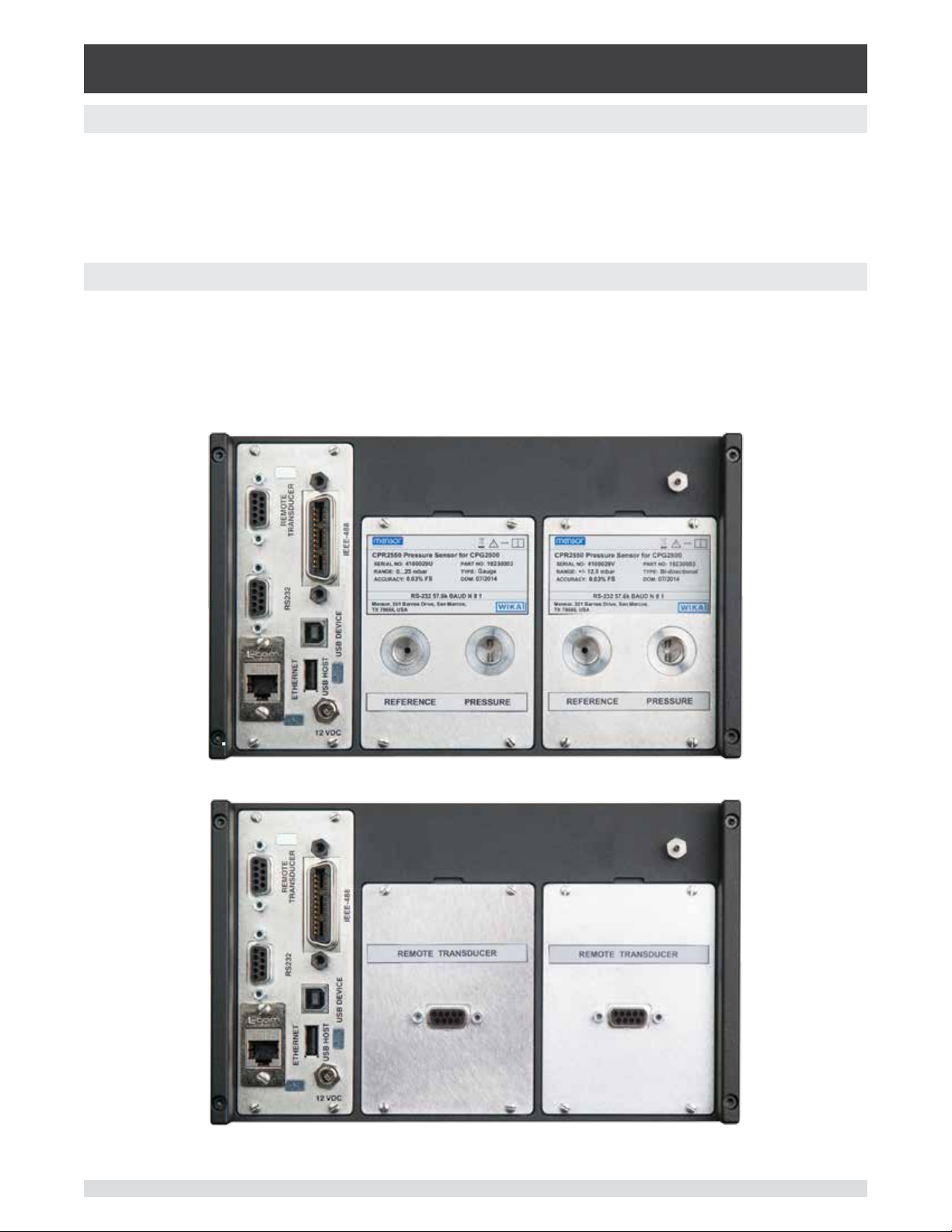
5.4 Rear Panel
Two slots are available on the rear of the CPG2500. These slots can be lled with a removable transducer
or a remote transducer interface connection. Gauge Transducers will have a reference and a pressure
port. Absolute transducers will have a plug in the reference port. If a barometer is installed a hose barb
tting will be installed in the upper right. Transducers with analog output will have an electrical connection. Positioned on the left side is a remote transducer connection, the RS-232, Ethernet, IEEE-488, USB
device connections for communication, the USB host connection and the 12 VDC power input.
Figure 5.4 A - Two removable gauge transducers installed
Figure 5.4 B - Two remote transducer interface connections installed
Operating Instructions - CPG2500 19
Page 20

Precision Pressure Indicator
CPG2500
5.4.1 Pressure Connections
Whenmakingupaconnectiontoano-ringadapterttingportuseaback-up
wrench to prevent over-stressing the threads in the manifold block.
i
Notice
For pressure range less than 6015 psi, the pressure ports on the rear are female 7/16 - 20 SAE/MS
straight threads per MS16142 and SAE J514 table 14. Connected adaptors require a tube tting boss
seal with an o-ring per MS33656. Mensor can provide a variety of adapter ttings (see Section 8 Options) with the instrument. Do not use sealant on ttings sealed with an o-ring. The integrity of each seal
is particularly important since even microscopic leaks can cause errors in pressure measurements. For a
pressure range greater than 6015 psi, a xed Autoclave F250C/HIP HF4 tting is attached
5.4.2 Pressure Port
The CPG2500 will precisely measure the pressure connected to the pressure port up to the full scale
range of the transducer installed.
5.4.3 Reference Port
The reference port is available on gauge units that have sensors that are not sealed gauge units. For
these units this port is available to connect to the reference side of the sensor. This port is normally left
open to atmosphere but may be connected to a stable reference pressure. In an absolute pressure transducer this port is plugged.
5.5 Remote Communication Connections
See Section 7, Remote Operation, for connections and commands for operation over IEEE-488, Ethernet, USB or RS-232 ports.
5.6 Power Up
Apply power to the power connector on the rear of the instrument using the power adaptor included, and
switch the power switch on the front of the unit ON. The instrument will go through an initialization process and system check. As soon as the system check is completed the system will default to a screen
similar to the one shown in Section 6.1.2 - Display Screen Features. The main measurement screen may
be congured in many dierent ways but initially it will be in a default conguration. Subsequently, the unit
will power up in the conguration that it was in when last powered o. Allow at least 15 minutes of warm
up before performing critical pressure measurements.
20 Operating Instructions - CPG2500
Page 21
Precision Pressure Indicator
CPG2500
6 Local Operation and Setup
6.1 General Operation
This section describes the procedures for operating the CPG2500 from the front panel. Instructions for
operating the device remotely from an external computer are covered in Section 7, Remote Operation. By
following the procedures provided in these two sections and Section 10, Calibration, you can expect your
CPG2500 to deliver maximum accuracy and dependability for many years of useful service.
6.1.1 Setup Applications
Conguration of the CPG2500 is achieved by changing settings accessed through the Application (“App”)
buttons. Local operation is accomplished by observing the data presented in the display. The appearance
and functionality of the display can be changed by pressing the App button for the related function. After
an app has been chosen, a set of related parameters will appear on the left. After choosing one of these
parameters, a set of selections related to that parameter will appear on the right or a data entry keypad.
The desired selection or data can be entered here.
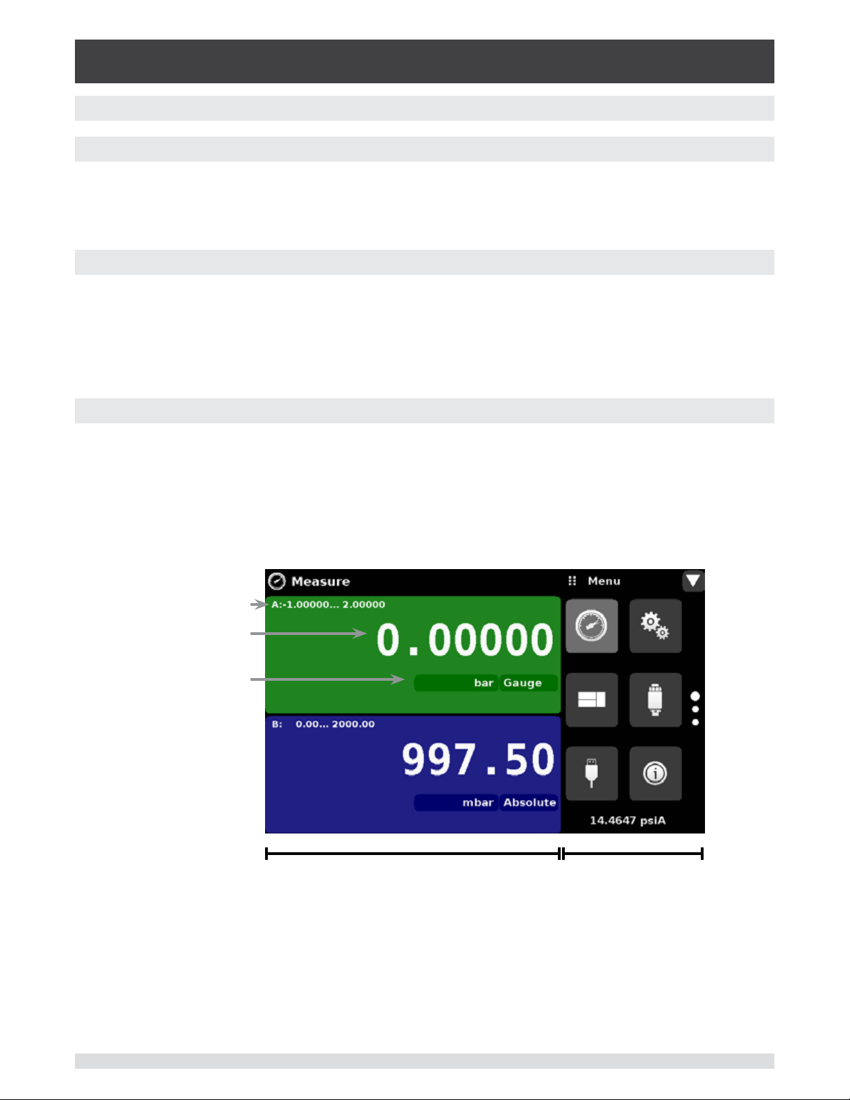
6.1.2 Display Screen Features
The screen shown below provides a brief description of the features shown on a 2 channel display after
initialization. The left two thirds of the display contains the area where information is displayed (in this
case the Measure Application) and the right one third contains the selection icons for each application.
Channels are color coded: Channel A is green, B is blue, C (remote) is red and the barometer is sky-blue.
Color coding persists throughout all channel-specic screens. A zero or tare button and auxiliary displays
(auxiliary units, rate and peak) will appear in the Measure App if activated. All of the CPG2500 screen
features are described in more detail throughout this manual.
Range
Reading
Pressure Units
and Mode
App Display / Parameter Selection
Figure 6.1.2 - Display Screen Features
App Selection /
Data Entry
Operating Instructions - CPG2500 21
Page 22
Precision Pressure Indicator
CPG2500
6.2 Initial Setup
Section 6.3.1 and 6.3.2 are provided rst so that the operator can initially check the information screen to
verify the installed components and to change the language if needed.
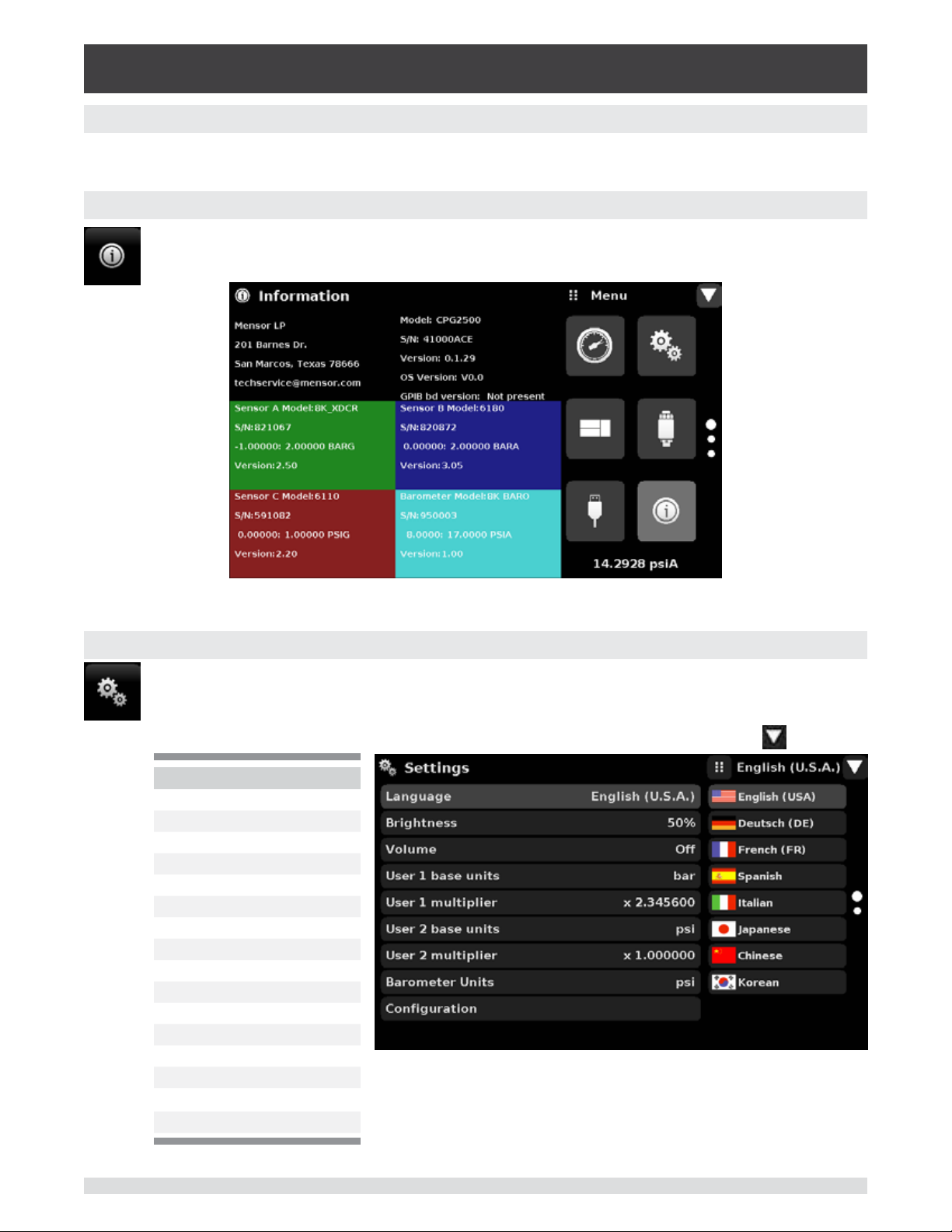
6.2.1 Contact and Version Information Application
Press this application button to display Mensor contact, installed sensor, instrument and
software version information.
6.2.2 Language Selection
Pressing the settings application button will open a screen where the language, display
brightness, volume, user base units/multiplier and conguration loading/saving, can be
changed. The current language selections available are shown in the table below. Additional
language choices will appear on the screen after pushing the Page Down button [
Language Country
English USA
German Germany
French France
Spanish Spain
Italian Italy
Chinese China
English Great Britain
German Switzerland
French Switzerland
Spanish Mexico
Russian Russia
Korean Korea
English Canada
French Canada
Polish Poland
Japanese Japan
Figure 6.2.1 - Information
]:
22 Operating Instructions - CPG2500
Page 23
Precision Pressure Indicator
CPG2500
6.3 Application Selection and parameter inputs
The application selection area on the right one third of the screen (see Figure 6.1.2 - Display Screen Features) is the area where setup, information and calibration Apps can be chosen. A second and third page
of application selections can be accessed by pressing the page down button [ ]. A series of vertically
placed circles on the center right indicates the active page by a larger circle. As each App is chosen,
related application parameters will appear on the left two thirds of the screen along with the name of the
application, and a reduced size icon in the top title section . When a parameter is chosen, related selections, sliding scales or a data entry key pad will appear in the input area on the right where the application
selection buttons were previously displayed. An example of each type of input is shown below. To return
to the App selection menu, simply press the menu button [
use of each selection and menu is intuitively apparent and will become second nature with minimal exposure to the menu structure.
] above the input area. The purpose and
App Title
Page Down
Menu Button
Input Title
Operating Instructions - CPG2500 23
Page 24
Precision Pressure Indicator
CPG2500
6.4 Applications:
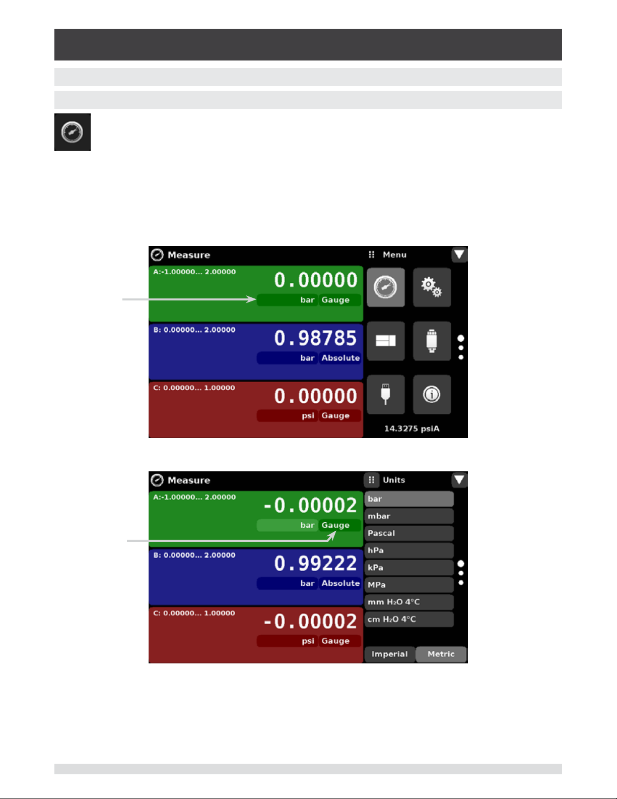
6.4.1 Measure Application
The Measure App is the normal operation screen referred to in previous instruments as the
‘main screen’. This application is dierent from the others in that it is not use to setup the conguration but is used to monitor the pressure applied to the installed transducers.
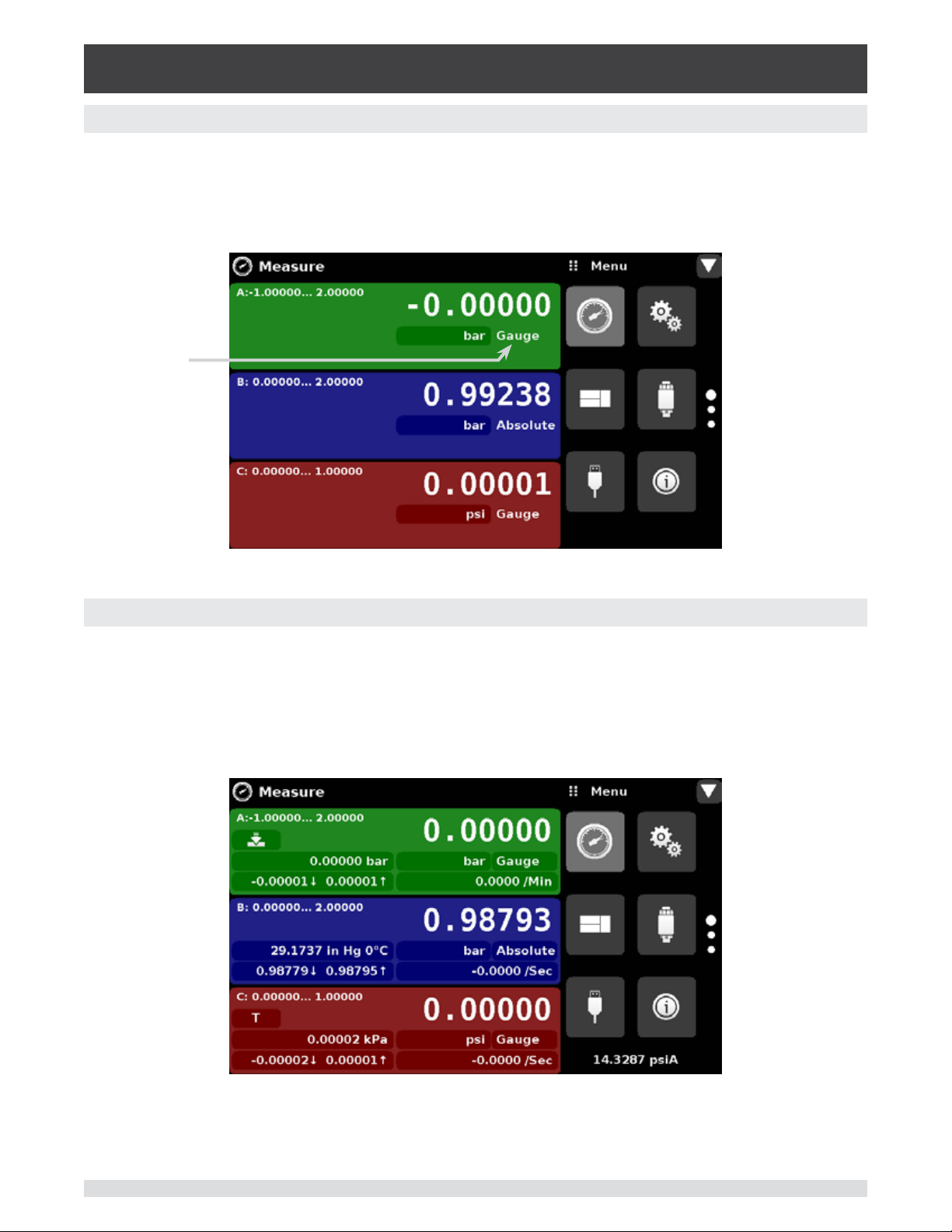
The screen in gure 6.4.1-A shows the basic Measure App in a three channel instrument. The units but-
ton is always present in each channel. When the units button is pressed a selection of imperial and metric
units will be displayed on the right (gure 6.4.1-B); notice that the Units button has a lighter background
when the selection menu is active. Any unit of measure can be selected for any channel. If a barometric
reference is installed, the Mode button, described below, will toggle from Gauge to Absolute mode when
pressed.
Units Button
Mode Button
Figure 6.4.1-A Basic Measure App
Figure 6.4.1-B - Units Change
24 Operating Instructions - CPG2500
Page 25
Precision Pressure Indicator
CPG2500
6.4.1.1 Pressure Mode / Emulation Mode
The Mode button is only active if there is an optional Barometric reference installed. Otherwise, the mode
button becomes a label (gure 6.4.1.1) indicating the native mode of the transducer (absolute or gauge).
When an optional barometric reference is installed, a native gauge transducer can emulate absolute
pressure using the barometric reference. Alternatively, a native absolute transducer can emulate gauge
pressure. Emulation can be activated simply by pressing the Mode button.
Without a
Barometer the
Mode button
becomes a label
Figure 6.4.1.1 - Mode Label
6.4.1.2 Auxiliary Displays
The screen in gure 6.4.1.2 shows all of the possible auxiliary display items that can be included in the
Measure App, in addition, each channel can contain one of two possible calibration functions. The auxiliary display item includes “Alternate Units”, “Peak” and “Rate”. Calibration functions are either a “Zero”
button or a “Tare” button. These auxiliary features will appear in the Measure App when selected from the
Transducer App (section 6.4.4.4).
Figure 6.4.1.2 - Three channel Measure App with auxiliary displays
Operating Instructions - CPG2500 25
Page 26
Precision Pressure Indicator
CPG2500
Auxiliary buttons can be placed in three dierent parts of the screen depending on how they are set in the
Transducer Application. Each auxiliary display can be modied by pressing the displayed button.
Peak: Pressing the Peak button will reset the upper and lower peak value to the current reading, subsequent negative or positive divergence from that reading will be recorded in the button.
Rate: Pressing the Rate button will display a choice of time rate units for the rate denominator.
Units: Pressing the Auxiliary Units button will display the same set of units available for the primary units.
Pressing any of these units will change the auxiliary units to that chosen unit.
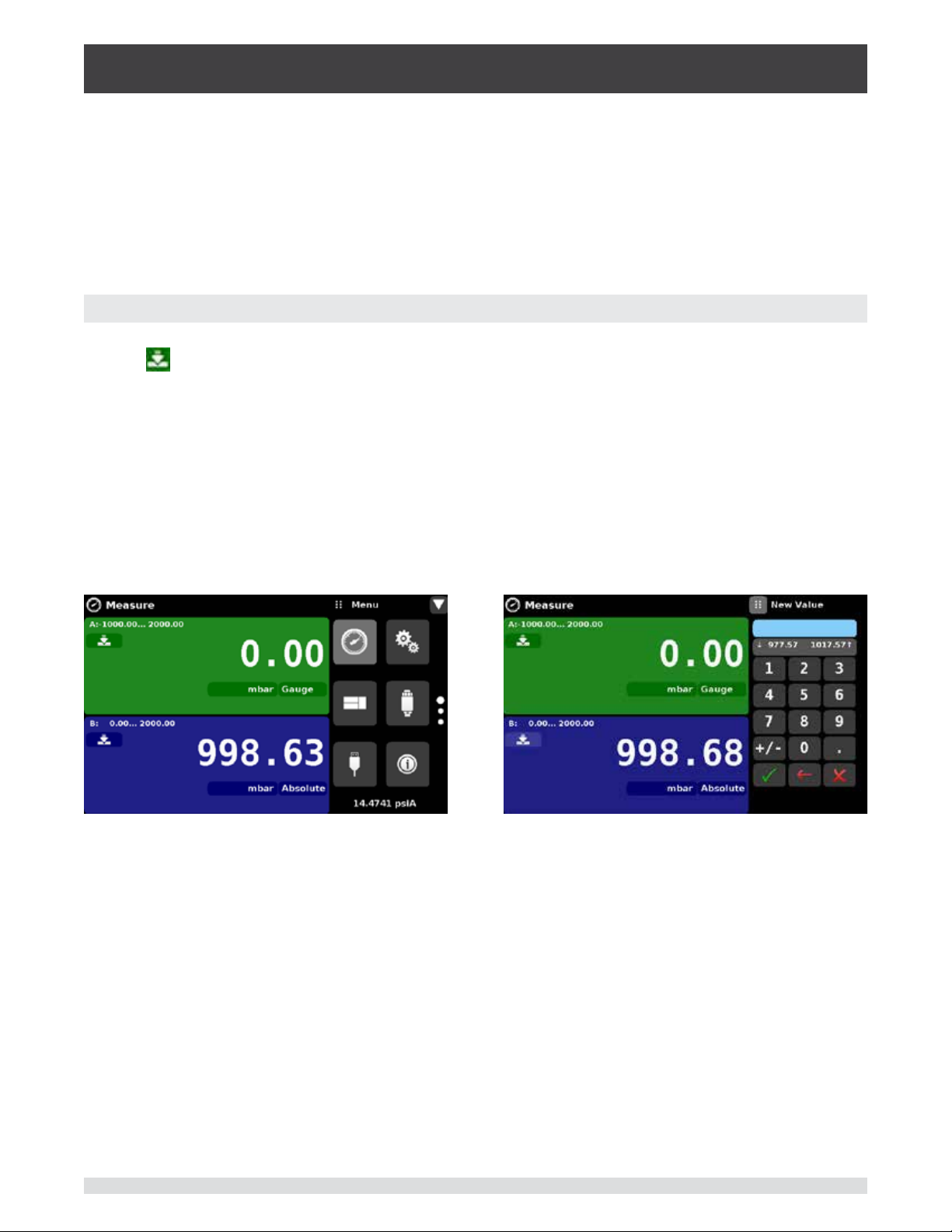
6.4.1.3 Zero Button
If the Zero Calibration function has been chosen in the Transducer App (section 6.4.4), then the Zero Cal
Button [
Cal Button is pressed, a keyboard will appear to allow a single point calibration. If the channel is measuring gauge pressure, pressing the button will set the current reading to zero. If the channel is in emulation
mode (absolute or gauge) then the value will not be saved to the sensor but only as a temporary adjustment while in emulation mode. After exiting the emulation mode or after a power cycle, the temporary
adjustment will be cleared. The zero adjustment for a channel not in emulation mode will be saved to the
sensor as if single point calibration had been performed.
] will appear in the Measure App. If the channel is measuring absolute pressure, and the Zero
Figure 6.4.1.4 shows two channels displayed, the zero cal function has been enabled for both channels.
The screen on the left shows both channels with zero buttons. The screen on the right shows the same
two channels, but the zero button on the absolute channel has been pressed, showing the keypad enabled to accept a new single point calibration value.
Figure 6.4.1.3 - Zero Button, Gauge - Absolute
The background color of the zero button will momentarily change to a lighter color as the zero calibration
is performed then will revert back to a darker color when complete.
26 Operating Instructions - CPG2500
Page 27

Precision Pressure Indicator
CPG2500
6.4.1.4 Tare Button
If the Tare calibration function has been chosen in the Transducer App (section 6.4.4), then the Tare Button [
screen at the same time, in the same channel. When the Tare button is pressed, the instrument will subtract the current pressure reading (the tare pressure) so that the indicator will display zero. Subsequent
deviations in pressure will be relative to the tare pressure. Notice in the gure below that, when active, the
back ground of the tare button is lighter than the channel background, when not active the button background is darker than the channel background.
] will appear in the channel screen. The Tare button and the Zero Button cannot appear on the
Tare button,
active.
Tare button,
inactive.
Figure 6.4.1.4 - Tare Button
Pressing the tare button again will deactivate the tare and change the pressure indication back to the
reading corresponding to the calibrated output of the transducer. An active tare will revert to a deactivated state after a power cycle.
Operating Instructions - CPG2500 27
Page 28

Precision Pressure Indicator
CPG2500
6.4.2 Settings Application
The Settings App is used to set up general settings for the display. Settings parameters include
Language, Brightness, Volume, User 1 base units, User 1 multiplier, User 2 base units, User 2
multiplier, Barometer units, and Conguration. Figure 6.4.2 shows these parameters as indicated when the Settings App has been chosen. As each parameter is pressed, an input screen will
appear on the right where selections can be made.
The Settings App provides a place to change the language, display brightness, volume, user units, and
barometer units. Conguration settings of the unit can also be saved within this application plus the default conguration can be activated.
Figure 6.4.2 - Settings application
6.4.2.1 Languages
The Language parameter provides a selection of dierent languages. Once a language is chosen all
words within all menus will appear in the chosen language and the radix character (decimal mark) will
change from a dot (.) to a comma (,) depending on the language chosen.
Figure 6.4.2.1 - Languages
28 Operating Instructions - CPG2500
Page 29

Precision Pressure Indicator
CPG2500
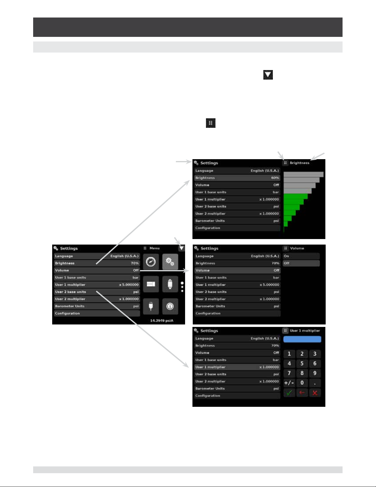
6.4.2.2 Brightness
The Brightness setting provides a sliding scale to increment the screen brightness in all screens. Sliding
your nger along the bar graph or touching anywhere in the bar graph will change the brightness of the
screen. After the setting is made and your nger is removed from the screen the menu will revert back to
the basic settings menu.
Figure 6.4.2.2 - Brightness
6.4.2.3 Volume
The Volume setting provides a way to turn on or o the touch screen audio feedback.
Figure 6.4.2.3 - Volume
Operating Instructions - CPG2500 29
Page 30

Precision Pressure Indicator
CPG2500
6.4.2.4 User base units / Base units multiplier
When choosing a unit of measure from the Measure Application (main screen), standard units can be
chosen in addition to two user dened units. User units 1 and 2 are dened in the Settings App using
“User 1 base units”, “User 1 multiplier” and / or “User 2 base units”, “User 2 multiplier”. For example, if the
display of one atmosphere (atm) was needed, then psi could be chosen as the “User 1 base unit” and
the “User 1 multiplier”, in this case, would be 0.068045. When set this way and the user 1 unit has been
chosen, the user 1 unit will now display the pressure in atm.
Figure 6.4.2.4 - User base units / Base units multiplier
6.4.2.5 Barometer Units
When the Barometer Units Parameter has been chosen, a list of Imperial or Metric units is presented on
the right side of the screen. Any of these units can be chosen from this list for the barometric readout that
can be seen on the bottom right of the Measure App.
Figure 6.4.2.5 - Barometer units
30 Operating Instructions - CPG2500
Page 31

Precision Pressure Indicator
CPG2500
6.4.2.6 Conguration
Conguration is the last parameter in the Settings App. It allows the operator to save instrument settings
and load them, as needed, in the future. Parameters that are set in the Settings App, the Frames App, the
Transducer App, and the Remote App can be saved using the Conguration “Save” button and recalled
using the Conguration “Load” button. Simply set all desired parameters then go to Settings-Conguration, press one of the numbered Conguration buttons then press the “Save” button. This will save the
current conguration in that button. To reload a saved conguration at a later time, go to Settings-Conguration and press the numbered conguration button corresponding to the saved conguration and then
press the “Load” button.
Figure 6.4.2.6 - Conguration
The instrument default conguration can be activated simply by pressing the “Default” Button.
Operating Instructions - CPG2500 31
Page 32

Precision Pressure Indicator
CPG2500
6.4.3 Frames Application
The Frame App allows the user to select the number and order of the transducer channels
displayed in the Measure Application. A total of three channels can be displayed at a time. Typically, if two internal transducers and one external transducer are installed the display will include
three channels: A, B and Remote, in order form top to bottom. The order and number of channels displayed can be dened in the Frames Application. In addition the optional barometric reference transducer can be displayed as a channel as well as an emulated Delta channel. Figure
6.4.3 shows the unit in dual frame format with the Frame Format set to display the readings from
two transducers (A & B in a dual frame mode).
Figure 6.4.3 - Frames Application
6.4.3.1 Frame Format
The Frame format button sets the display in the Measure Application to Single Frame, Dual Frame or
Triple Frame. Figure 6.4.3.1 shows the available selections for the Frame Format parameter.
Figure 6.4.3.1 - Frame Format
32 Operating Instructions - CPG2500
Page 33

Precision Pressure Indicator
CPG2500
6.4.3.2 Frames Channel
The channel setting in the Frames application provides a way to choose which channel(s) appears and in
what order within the Measure Application (Main Screen). Any installed transducer channel or the emu-
lated Delta channel can be displayed in the Measure Application. In gure 6.4.3.2, the Dual Frame format
is set in the Frames format parameter, channel A is set as the top frame and Channel B is set as the bottom frame. Channels A, B, Remote or Barometer could be placed in any available position. If the Single
or Triple frame format is chosen then the channels will appear as shown in each of the respective frame
position sets.
Frame
positions sets:
Single Frame
Dual Frame
Triple Frame
Resulting view in the Measure Application
Figure 6.4.3.2 - Frames Channel
In Figure 6.4.3.2-A, the Channels have been set in order for each frame format and the frame format has
been set to “Frame triple”. In the Measure App the resulting channel position will be: channel “A’ on top,
Channel “B” in the middle and the “Delta” channel on the bottom. The barometer reading (if installed) will
appear as a selectable channel and will always be in the bottom right under the application menu.
Figure 6.4.3.2-A - Example channel frame settings
Operating Instructions - CPG2500 33
Page 34

Precision Pressure Indicator
CPG2500
6.4.4 Transducer Application
For each transducer, the Transducer Application provides a way to set the lter for the reading to
reduce uctuations due to electrical noise, and to set the resolution of the reading. In addition,
the auxiliary display functions and calibration function can be specied here.
Figure 6.4.4 - Transducer Application
6.4.4.1 Transducer Channel Selection
To set the transducer parameters, the transducer channel must be selected. Transducer parameters are
identical for all channels but can be set dierently in each channel. Figure 6.4.4.1 shows two displays
where channel “A” and “B” have been selected.
Figure 6.4.4.1 - Transducer Channel Selection
34 Operating Instructions - CPG2500
Page 35

Precision Pressure Indicator
CPG2500
6.4.4.2 Transducer Delta Emulation
If there is more than one transducer installed, the Delta Channel option will appear as a selection in the
Transducer App. The Delta channel has all of the regular transducer parameters in addition to the Delta
Function shown at the bottom of Figure 6.4.4.2. When the Delta Function is selected settings will appear
that dene the delta display (in the Measure App). All discrete combinations for adding or subtracting
one channel from another are available as a selection. These combinations are shown below in Figure
6.4.4.2.
Figure 6.4.4.2 - Transducer Delta Emulation
6.4.4.3 Transducer Filter
The Filter is an electronic lter to smooth out the pressure readings. Because of dierences in resolution,
greater ltering may display a more stable reading for some pressure units. Turn o the Filter by selecting
“O”, select varying degrees of ltering for the current units by selecting “Low”, “Normal” or “High”.
Figure 6.4.4.3 - Transducer Filter
Operating Instructions - CPG2500 35
Page 36

Precision Pressure Indicator
CPG2500
6.4.4.4 Transducer resolution
The Resolution of each transducer Channel can be set in the Transducer Application using the resolution
Parameter. The resolution can be set to 4, 5 or 6 digits.
Figure 6.4.4.4 - Transducer Resolution
36 Operating Instructions - CPG2500
Page 37

Precision Pressure Indicator
CPG2500
6.4.4.5 Auxiliary Displays
The Transducer Channel Auxiliary Display(s) can be set in the Transducer App by selecting Auxiliary Display 1, 2 or 3 and selecting from, None, Peak, Rate or Units. Figure 6.4.4.5-A shows auxiliary display 1, 2
and 3 set for units, peak and rate respectively. Auxiliary displays will appear in the Measure App as seen
in Figure 6.4.4.5-B.
Figure 6.4.4.5-A - Transducer channel aux displays set to Units, Peak and Rate
Figure 6.4.4.5-B - Auxiliary displays as seen in the Measure App
Operating Instructions - CPG2500 37
Page 38

Precision Pressure Indicator
CPG2500
6.4.4.6 Cal Function
The Transducer Cal Function presents a choice of None, Tare or Zero. Choosing Zero will enable the Zero
Cal Button [
App. The Tare button and the Zero Button cannot appear on the screen at the same time, in the same
channel. See section 6.4.1.3 and 6.4.1.4 for operation of the Zero and Tare buttons in the Measure App
(main screen).
] in the Measure App. Choosing Tare will enable the Tare Button [ ] in the Measure
Figure 6.4.4.6 - Cal Function
38 Operating Instructions - CPG2500
Page 39

Precision Pressure Indicator
CPG2500
6.4.5 Remote Application
With the remote application you can select the remote command set for all interfaces. The GPIB address,
Ethernet network parameters and Serial parameters can also be set here.
Details about the Remote Operation (command sets, cable requirements, etc.) can be found in Section 7,
Remote Operation.
IEEE-488
Ethernet
Serial
RS-232 or
USB
Figure 6.4.5 - Remote Application
6.4.5.1 Remote Command Set
The remote command set parameter provides a choice of the Mensor command set or the WIKA SCPI
command set. Both sets of commands are listed in Section 7, Remote Operation.
Figure 6.4.5.1 - Remote Command Set
Operating Instructions - CPG2500 39
Page 40

Precision Pressure Indicator
CPG2500
6.4.5.2 Remote Communication Settings
The remainder of the Parameters in the Remote Application present the choice of a numeric entry, a
numeric address entry, or a radio button selection. The parameters that require a numeric entry will
present a numeric keypad with min and max limits for the variable. The parameters that require a numeric
address (for example an IP address) will also present a keypad. Address entries should conform to the
format of the parameter selected. The three screens below show examples of each type.
Numeric entry
Numeric address entry
Radio button selection
Setting the Ethernet DHCP to
yes will have a short delay while
i
an error will be indicated. If DHCP is
enabled, the IP address, Netmask and
Gateway are greyed out and locked, these
are controlled by the DHCP server.
the DHCP server is contacted.
If a DHCP server is not found,
Figure 6.4.5.2 - Remote Communication Settings
40 Operating Instructions - CPG2500
Page 41

Precision Pressure Indicator
CPG2500
6.4.6 Info Application
The Info application displays information about the instrument, including:
• Mensor address, and email
• Model number, serial number and operating software version.
• Sensor model number, serial number, range, software version
Figure 6.4.6 - Info Application
Operating Instructions - CPG2500 41
Page 42

Precision Pressure Indicator
CPG2500
6.4.7 Leak Test Application
The Leak Test application provides a way to check the system for leaks into or out of the system.
This App is found on the second page of the Apps menu accessed by pressing the page down
button [
The operator denes a leak by setting the Time parameter and the Delta parameter. With the system
pressurized to a predetermined amount, the leak test is initiated by pressing the Start button. If the
change in pressure exceeds the Delta parameter before the allotted time in the Time parameter, then
the Leak Test App will return a red status indication showing the actual dierence (delta) in pressure
recorded during time period set in the leak test, indicating a “failed” test. Otherwise it will return a green
status indication showing that the delta was not exceeded for the time period, indicating a “passed” test.
See Figure 6.4.7-A for examples of a failed and a passed test.
].
Figure 6.4.7 - Leak Test
Figure 6.4.7-A - Leak test fail (left) & Leak test pass (right)
42 Operating Instructions - CPG2500
Page 43

Precision Pressure Indicator
CPG2500
6.4.8 Troubleshooting Application
The Troubleshoot Application will display information about error conditions and remote com-
munications. Within the troubleshoot screen (Figure 6.4.8-B), push the Error button to display
any errors that have occurred in the instrument due to a communication or network error. Push
the Remote button to show commands and responses that have been sent over the remote
communication connection.
If there are any errors in the error queue an error symbol [
] will appear in all screens (Figure 6.4.8A) of the instrument. Pressing this error button from any screen will open the Troubleshoot application
where the error can be viewed.
Figure 6.4.8-A - Error indication
Figure 6.4.8-B - Troubleshoot error and remote
Operating Instructions - CPG2500 43
Page 44

Precision Pressure Indicator
CPG2500
6.4.9 Service Application
The service application is a password protected area where calibration of all connected sen-
sors can be accomplished. In addition, this is where the password for entering this area can be
changed.
Figure 6.4.9-A - Service Application (locked)
Press the Enter button to show the numeric keypad to enter a password. This will unlock other applications. Default password is 123456. Enter 123456 and press the check mark [
Application.
Figure 6.4.9-B - Service Application (Enter Password)
] to unlock the Service
Note: The default Password is 123456. After entering this for the rst time, the password can
i
44 Operating Instructions - CPG2500
be changed.
Page 45

Precision Pressure Indicator
CPG2500
6.4.10 Unlocked Service Application
After the Password has been entered, the unlocked Service Application will appear (Figure 6.4.10). To
re-lock this screen, press the lock button.
Figure 6.4.10 - Unlocked Service Application
From the Unlocked Service Application, the Password can be changed by pressing the Enter button next
to the Change Password label. This will open a keypad where a new password can be entered and accepted by pressing the Check Mark [
Note: Please make note of a password change and save the new password in a secure
i
The Unlocked Service Application is the access point to all calibration screens described in Section 10 of
this manual.
i
location.
Note: Recommended calibration setup and explanation of calibration screen applica-
tions is covered in Section 10 of this manual.
].
Operating Instructions - CPG2500 45
Page 46

Precision Pressure Indicator
CPG2500
NOTES
46 Operating Instructions - CPG2500
Page 47

Precision Pressure Indicator
CPG2500
7 Remote Operation
Use the screens in Section 6.4.5 Remote Application to set the operating parameters for the instrument
command set, Ethernet, Serial (RS-232) and IEEE-488 (GPIB) information.
7.1 Command Set
Command Set button – Users’ can select which model remote protocol they would like to emulate for
simulation and testing purposes. Selections may include the following or may be added per customers’
specications:
• Mensor (default)
• SCPI WIKA (The SCPI WIKA mode emulates the WIKA command set in SCPI format.)
7.2 IEEE-488
IEEE-488 address button – Allows the user to set the GPIB address by inputting a numeric value utilizing
the touch screen.
7.2.1 IEEE-488.2 Commands
Command or Query Response / Function
*IDN? Returns identication string
*RST Reset to known state (default+psi)
*TST? Returns 1
*OPC Operation completed
*WAI Returns operation completed state
*CLS Clear status and error queue
*ESE Enable status event
*ESE? Returns enable status even value
*ESR Event status register
*ESR? Returns even status register value
*SRE Service request enable
*SRE? Returns service request enable value
*STB? Returns status byte
Operating Instructions - CPG2500 47
Page 48

Precision Pressure Indicator
CPG2500
7.3 Ethernet
The Ethernet function allows the user to set the following by inputting a numeric value in each separate
eld:
• IP
• Netmask
• Gateway
• Port
• DHCP settings
Set the Ethernet communication parameters as described in Section 6.4.5.
!
Caution
!
Caution
The Ethernet communication port allows the CPG2500 to communicate with computers using
10/100Based-T specications.
Before using Ethernet communication, four parameters must be set up: IP, Netmask, Gateway, and Port.
CAUTION: Please contact your network administrator for
proper settings.
CAUTION: Please consult your computer resources department prior to connect-
ingthisinstrumenttoyournetworktoverifytherearenoconictswithexistingIP
addresses.
48 Operating Instructions - CPG2500
Page 49

Precision Pressure Indicator
CPG2500
7.4 Serial
Set the Serial communication parameters as shown in Section 6.4.5 Remote Application. The serial communication port allows the CPG2500 to communicate in RS-232 format with computers, terminals, PDAs,
or similar hosts.
These parameters should be set to match your host computer. Default settings are: 9600 baud, 8 data
bits, 1 stop bit, no parity, and no echo.
If echo is ON, the CPG2500 will immediately echo back characters sent over the serial port. The Serial
function allows the user to set the RS-232 serial port settings by selecting from the choices provided:
• Baud
9600
19200
38400
57600
115200
• Data Bits
7
8
• Stop Bits
1
2
• Parity
Even
Odd
None
• Echo settings
On
O
7.4.1 Serial Cable Requirements
RS-232 communications are transmitted over a three conductor, shielded cable terminated in a standard
DB9 connector on the instrument end, and a dierent gender connector on the host end. The proper pin-
outs are shown in the following illustration.
CAUTION: When replacing an older model DPG 2100, the serial cable should be
replaced with a straight cable or a null-modem inserted in the line.
!
Caution
Operating Instructions - CPG2500 49
Page 50

Precision Pressure Indicator
CPG2500
7.5 Mensor Command Set
This Mensor command set is the default on the CPG2500. For queries (ending with a ?), the Data column
represents the response of the CPG2500. All response strings begin with a space character or an “E”
representing that there is an error in the error queue. All response strings are terminated with a <CR>
and a <LF>. The error queue holds the last 10 errors identied.
For all commands (no ?), the data column represents the required parameters to be sent to the CPG2500
following the string in the command column. For any command that requires multiple parameters to be
sent, the parameters must be separated by commas.
7.6 Command and Query Format
Commands must be sent in ASCII format and terminated with either a carriage return (<cr>), linefeed
(<lf>), or both. Commands are not case sensitive. Each query returns a response. If an error is detected
the response will include an error ag.
CommandorQueryeld: Unless otherwise specied, commands are typically converted to queries
by appending a question mark to the command. Table 7.9 lists all of the CPG2500 command or query
keywords.
Dataeld:The data eld is either in ASCII {string} or numeric {value} form. In the case of multiple data
elds, commas are required to separate the elds. Queries do not have a data eld. String (text) or value
(numeric) data are acceptable in any of the following formats:
Examples of {string} data: ON, OFF, mBar, inHg
Examples of {value} data: 1, 1.0, -5.678, 25.68324e-5
7.7 CommandSetDenitions
In this manual a data entry made up of alpha characters is dened as a string, as opposed to data
containing only numbers, such as “Enter 1 for ON or 0 for OFF” where 1 and 0 are dened as values.
Command: Any command or query listed in Table 7.9. For commands that take boolean data the following strings are acceptable:
0 1
False True
No Yes
O On
Separator: Space (SP).
Data: ASCII representations of numbers, {value}, or alpha characters, {string}, data as dened above.
When sending code a literal variable replaces the brackets and the enclosed character(s) shown in the
following examples.
Termination: Linefeed (LF) or carriage return (CR) is used to signal the end of a command statement.
For IEEE-488.2 operation “EOI” is an acceptable alternative.
Always send commands in one of the following formats:
1. [Command] [Termination];
2. [Command] [Separator] [Data] [Termination];
3. Queries are special instructions in the form: [Command?] [Termination] where the question mark, “?”,
immediately precedes the terminator.
When a valid query is received, the CPG2500 will return {data} terminated by CR and LF. Floating point
data is returned in the current engineering units in exponential format.
50 Operating Instructions - CPG2500
Page 51

Precision Pressure Indicator
CPG2500
7.8 Output Formats
Pressure readings are returned in exponential notation in a format according to the OUTFORM command
as follows. Outform applies to both pressure channels.
1. <sp> pressure value <cr><lf>
2. <sp> pressure, units number,STANDBY <cr><lf>
3. <sp> pressure, pressure rate <cr><lf>
4. <sp> pressure, minimum peak, maximum peak <cr><lf>
7.9 CPG2500 Commands and Queries
Table 7.9 lists all of the current CPG2500 commands and queries.
Channelspeciccommandsaresenttoonlytheactivechannel.
i
Notice
Optional emulation modes are available in which a CPG2500 can emulate remote functions of dierent
brands of pressure gauges. Please contact Mensor for more details.
See ‘CHAN’ command.
Table 7.9 - CPG2500 Commands and Queries
Command Data Response/Function
? See Table Below Returns data per the current output
format
A? <sp>n.nnnnne+nn<cr><lf> Returns the A channel pressure read-
ing
AR? <sp>n.nnnnne+nn<cr><lf> Returns the A channel rate
Acquire? 15 char string.
Ex:
Acquire? Test_stand_1
Returns:
<sp>(YES or NO), CCC…
CCC<cr><lf>
Address 1-31 Sets the GPIB Address
Address? <sp>nn<cr><lf> Returns the GPIB Address
Asset_tag 16 char string General purpose string for customer
Asset_tag? <sp>sssssssss<cr><lf> Return customer asset tag string
This command is used when multiple
computers would like to control the
instrument.
Yes if acquisition is successful.
No if instrument is being controlled
with another computer.
See: Release? and Unlock
use.
B? <sp>n.nnnnnE+nn<cr><lf> Returns the B channel pressure read-
ing
BR? <sp>n.nnnnnE+nn<cr><lf> Returns the B channel rate.
Baro? <sp>+n.nnnnnE+nn<cr><lf> Returns reading from barometric sen-
sor or “NO BAROMETER” if one isn’t
installed
Operating Instructions - CPG2500 51
Page 52

Precision Pressure Indicator
CPG2500
C? <sp>n.nnnnnE+nn<cr><lf> Returns the C channel pressure read-
ing
CR? <sp>n.nnnnnE+nn<cr><lf> Returns the C channel rate
Calculate_as_found_lin-
earity
Caldisable YES,NO Sets whether or not the ability to cali-
Caldisable? <sp>(YES or NO)<cr><lf> Returns whether or not the ability to
Cerr None Clears the error queue
Chan A, B, C, D Sets the active channel
Chan? <sp>X<cr><lf> Returns the active channel
Chanfunc n, func<cr><lf> Sets the auxiliary display function
Chanfunc? <n> <sp>CCCCC…<cr><lf> Returns the auxiliary display function
Cmdset Mensor, SCPI Activates remote command set for
Cmdset? <sp><CCCCC...<cr><lf> Returns active command set identier
Calculate linearity slopes and inter-
cepts from true/actual pressures
brate the sensors is disabled
calibrate the sensors is disabled
where “n” is the auxiliary display to be
set (1,2, or 3) and “func” is the function
(none, peak, rate, units)
specied by “n” for the active channel
instrument emulation modes
D? <sp>n.nnnnne+nn<cr><lf> Returns the D channel pressure read-
ing
DR? <sp>n.nnnnne+nn<cr><lf> Returns the D channel rate
Decpt? <sp>n<cr><lf> Returns the number of decimal points
(see Resolution)
Default None Sets the default values
Deltafunc A+B, A+C, B+C, A-B, A-C, B-A, B-C,
C-A, C-B
Sets the delta to be the result of the
specied function
Deltafunc? <sp>CCC<cr><lf> Returns the delta function
DHCP ON or OFF Reserved for DHCP setup
DHCP? <sp>(YES or NO)<cr><lf> Reserved for DHCP setup
DOC mm/dd/yyyy Sets the date of cal for the active
channel’s sensor
DOC? <sp>mm/dd/yyyy<cr><lf> Returns the date of cal for the active
channel’s sensor
DOM? <sp>mm/dd/yyyy<cr><lf> Returns the date of manufacture
Error? <sp> text description <cr><lf> Returns the next error in the error
queue
Filter OFF, LOW, NORMAL, HIGH Sets the reading lter 0, 80%, 92%,
95%
Filter? <sp> (lter)<cr><lf> Returns the reading lter
Gasdensity Value in lb/cuft, or “NITROGEN” or
“DRYAIR”
Sets the head pressure gas density in
lb/cuft
52 Operating Instructions - CPG2500
Page 53

Precision Pressure Indicator
CPG2500
Gasdensity? <sp>+n.nnnnnE+nn<cr><lf> Gets the head pressure gas density in
lb/cuft
Gastemp Value in degrees F Sets the head pressure gas tempera-
ture
Gastemp? <sp>+n.nnnnnE+nn<cr><lf> Gets the head pressure gas tempera-
ture
Gateway nnn.nnn.nnn.nnn Sets the Ethernet gateway address
Gateway? <sp>nnn.nnn.nnn.nnn<cr><lf> Gets the Ethernet gateway address
Height Value in inches Sets the head pressure height in
inches
Height? <sp>+n.nnnnnE+nn<cr><lf> Gets the head pressure height in
inches
Id? <sp>MENSOR,
CPG2500, ssssss,
v.v.vv<cr><lf>
IP nnn.nnn.nnn.nnn Sets the IP address of the instrument
IP? <sp>nnn.nnn.nnn.nnn<cr><lf> Returns the IP address of the instru-
Keylock YES or NO Locks or unlocks the entire touch
Keylock? <sp>(YES or NO)<cr><lf> Returns Yes or No
List? <sp>PRI,1<cr><lf> Legacy query
Listcal? <sp>PRI, {sn},1,{mmddyy}<cr><lf> Returns the calibration date of the ac-
Listrange? <sp>PRI,1,min,max<cr><lf> Returns the range of the active sensor
Localgravity Value in ft/s^2 Sets the local gravity in feet/sec^2
Localgravity? <sp>+n.nnnnnE+nn<cr><lf> Returns the local gravity in feet/sec^2
Netmask nnn.nnn.nnn.nnn Sets the Ethernet network mask
Netmask? <sp>nnn.nnn.nnn.nnn<cr><lf> Gets the Ethernet network mask
Outform 1 to 4 – see Section 7.9 Sets the output format
Outform? <sp>X<cr><lf> Returns the output format – see table
Peakmax? <sp>n.nnnnnE+nn<cr><lf> Returns the maximum pressure since
Peakmin? <sp>n.nnnnnE+nn<cr><lf> Returns the minimum pressure since
Peakreset None Resets the peak values.
Port nnnnn Sets the Ethernet port of the instru-
Port? <sp>nnnnn<cr><lf> Returns the Ethernet port of the instru-
Ptype Absolute or Gauge Sets the instrument pressure type –
ssssss is the serial number,v.v.vv is
the CPG2500 software version
ment
screen
tive sensor
below
peakreset was sent
peakreset was sent
ment
ment
emulation only works if the optional
barometric sensor is installed
Operating Instructions - CPG2500 53
Page 54

Precision Pressure Indicator
CPG2500
Ptype? <sp>CCCCC<cr><lf> Returns “Absolute” or “Gauge” for the
pressure type
RangeMax? <sp>n.nnnnnE+nn<cr><lf> Returns the maximum range of the ac-
tive transducer in the current units
RangeMin? <sp>n.nnnnnE+nn<cr><lf> Returns the minimum range of the ac-
tive transducer in the current units
Rate? <sp>n.nnnnnE+nn<cr><lf> Returns the rate reading of the instru-
ment in current units/current time unit
(see: Runits)
Rdecpt? <sp>n<cr><lf> Returns the number of rate decimal
points (see: Resolution)
Release? 15 char string.
Ex:
Release? Test stand 1
Returns:
<sp>(YES or NO), CCC…
CCC<cr><lf>
Resolution <n> Sets the number of signicant digits
Resolution? <sp>n<cr><lf> Returns the number of signicant dig-
Rlter Value in % Sets the % of the rate lter
Rlter? <sp>n.nnnnnE+nn<cr>
<lf>
Runits Sec, min, hr Sets the rate time unit
Runits? <sp>XXXX<cr><lf> Returns the rate time unit
Save_cal Save calibration values
Save_linearity Save linearity values
Sbaud 9600, 19200, 38400, 57600, 115200 Sets the serial baud rate
Sbaud? <sp>XXXX<cr><lf> Returns the serial baud data
Sdata 7 or 8 Sets the serial data bits
Sdata? <sp>n<cr><lf> Returns the serial data bits number
Sensorid? <sp>Mensor,SN XXXXXX, VN.NN Returns the active sensor’s serial
Span desired pressure or ? Sets span on active transducer or for
Span? <sp>XXXXXXX<cr><lf> Returns span scale factor for active
Sparity Even, ODD, NONE Sets the serial parity
Sparity? <sp>CCCC<cr><lf> Returns the serial parity
This command is used to release
control of the instrument in a multiple
computer environment.
Yes if release is successful
No if instrument is being controlled
with another computer
CCC… = name of controlling computer or AVAILABLE
See: Acquire? and Unlock
(see: decpt)
its (see: decpt)
Returns the rate lter
number and rmware version
?, clears previous value, must be >
50% FS and has a 1% limit. CALDISABLE must be OFF/NO.
transducer
54 Operating Instructions - CPG2500
Page 55

Precision Pressure Indicator
CPG2500
Sstop 1 or 2 Sets the serial stop bits
Sstop? <sp>X<cr><lf> Returns the serial stop bits
Ta r e ON / OFF Tares the reading to zero
Tare? <sp> n.nnnnnE+nn <cr><lf> Returns value of Tare
Transfer_factory_to_lin-
earity
Units units code or text in table below Sets the instrument engineering units
Units? <sp>CCCC<cr><lf> Returns the instrument units in a text
Unlock None Releases Acquire locks (see: Acquire? )
Window Value in current units Sets the exponential lter window for
Window? <sp>n.nnnnnE+nn
<cr><lf>
Zero desired pressure or ? Sets zero to set pressure or for ?,
Zero? <sp>n.nnnnnE+nn
<cr><lf>
Copy factory linearity coecients to
customer
string
or (see: Release?)
the active sensor
Returns the exponential lter window
for the active sensor
clears previous value. CALDISABLE
must be OFF/NO
Returns zero oset for active transducer
Note:
Except for the engineering units selection, the numeric sux selects the applicable channel/sensor:
1 = Channel A
2 = Channel B
3 = Channel C
4 = Channel D
5 = baro (if installed)
This numeric sux always defaults to 1 and is designated by [C] (channel)
Operating Instructions - CPG2500 55
Page 56

Precision Pressure Indicator
CPG2500
7.9.1 Units Command Syntax for Measurement Units
n Description Output Format Type
1 pounds per square inch PSI Imperial
2 inches of mercury @ 0°C INHG Imperial
3 inches of mercury @ 60°F INHG Imperial
4 inches of water @ 4°C INH2O Imperial
5 inches of water @ 20°C INH2O Imperial
6 inches of water @ 60°F INH2O Imperial
7 feet of water @ 4°C FTH2O Imperial
8 feet of water @ 20°C FTH2O Imperial
9 feet of water @ 60°F FTH2O Imperial
10 millitorr MTORR Metric
11 inches of sea water @ 0°C INSW Imperial
12 feet of sea water @ 0°C FTSW Imperial
13 atmospheres ATM Imperial
14 bars BAR Metric
15 millibars MBAR Metric
16 millimeters of water @ 4°C MMH2O Metric
17 centimeters of water @ 4°C CMH2O Metric
18 meters of water @ 4°C MH2O Metric
19 millimeters of mercury @ 0°C MMHG Metric
20 centimeters of mercury @ 0°C CMHG Metric
21 torr TORR Metric
22 kilopascals KPA Metric
23 pascals PA Metric
24 dynes per square centimeter DY/CM
25 grams per square centimeter G/CM
26 kilograms per square centimeter KG/CM
2
2
2
27 meters of sea water @ 0°C MSW Metric
28 ounce per square inch OSI Imperial
29 pounds per square foot PSF Imperial
30 tons per square foot TSF Imperial
32 micron of mercury @ 0°C mHG Metric
33 tons per square inch TSI Imperial
34 hectapascals HPA Metric
36 megapascals M PA Metric
37 millimeters of water @ 20°C MMH2O Metric
38 centimeters of water @ 20C CMH2O Metric
39 meters of water @ 20°C MH2O Metric
Metric
Metric
Metric
56 Operating Instructions - CPG2500
Page 57

Precision Pressure Indicator
CPG2500
7.9.2 CPG2500 Error Codes
Code Serial Poll Byte Description Error String Returned
E00 00h No errors NO ERRORS
E05 45h Parameter error EGPIB PARAMETER ERROR: String that was sent
E07 47h Syntax error EGPIB SYNTAX ERROR: String that was sent
7.9.3 SCPI Commands and Queries
STATu s
:OPERation
:CONDition? Returns an integer value representing instrument status that
can be decoded.
Bit 0: Zeroing activ
Bit 1: Control Setpoint has not been reached.
Bit 2: Reserved 0.
Bit 3: Reserved 0.
Bit 5: Measuring. The instrument is actively measuring
MEASure
[:PRESsure][C]? Returns the pressure from Channel [C]
:TEMPerature[C]? Returns the temperature from Channel [C]
:RATE[C]? Returns the rate/sec from Channel [C]
:BAROmetric? Returns the barometric pressure
CALibration
[:PRESsure][C]
:MODE? Returns 1=calibrated or 0=not calibrated
:DATE? Returns date of cal “MM/DD/YY”
:DATE <i,i,i> Sets date of cal YYYY,MM,DD
:ZERO? Returns zero oset
:ZERO <n> Sets the zero oset
:ZERO:INITiate Ignored
SENSe
[:PRESsure][C]
:NAME? Returns sensor name string
:MODE? Returns “ABSOLUTE” or “GAUGE”
:MODE ABS|GAUGE Sets pressure type
:ABS? Returns native sensor type 0=GAUGE 1=ABSOLUTE
:RESolution? Returns resolution (oat)
:RANGe
[:UPPer]? Returns maximum range
:LOWer? Returns minimum range
:UNIT
[:NAME]? Returns ASCII units (mixed case)
:VALue? Returns the units conversion factor
:REFerence
[:HEIGht] <n> Sets the head pressure height in cm
Operating Instructions - CPG2500 57
Page 58

Precision Pressure Indicator
CPG2500
:HEIGht? Returns the head pressure height in cm
:MODE? Returns “OFF”, “GAS”, or “LIQUID”
:MODE OFF | GAS | LIQUID Sets the head pressure mode
:MEDium<n> Sets the medium density
:MEDium? Returns medium
:ACTive <C> Sets the active channel
ACTive? Returns the active channel
SYSTe m
:DATE <i,i,i> Not used, kept for backwards compatibility
:DATE? Not used, does not cause an error, does not return a response
:TIME <i,i,i> Not used, kept for backwards compatibility
:TIME? Not used, does not cause an error, does not return a response
:ERRor[:NEXT]? Returns error code, description
:KLOCk ON | OFF | 1 | 0 Sets the keylock state
:PRESet Load known state values
:SAVe No function (not needed)
:VERSion? Returns SCPI version 1994.0
TEST
:ELECtronic? Returns “OK”
UNIT
:[PRESsure] bar | mbar | Pa | psi Sets the pressure units
:[PRESsure]? Returns the pressure units
:NAME<n>? Returns the units string for units code <n>
:FACTor <n>? Returns the units conversion for units code <n>
:INDEX <n> Sets the index number.
:INDEX?
Returns the index number.
index unit
0 bar
1 mbar
2 Pa
3 psi
4 atm
5 kp/cm2
6 lbf/ft2
7 kPa
8 cmH2O(4°C)
9 inH2O(4°C)
10 inH2O(60°F)
11 ftH2O(4°C)
12 µmHg(0°C)
13 mmHg(0°C)
14 cmHg(4°C)
15 inHg(0°C)
16 inHg(60°F)
17 - 18 user
19 user
20 user
58 Operating Instructions - CPG2500
Page 59

Precision Pressure Indicator
CPG2500
7.9.4 SCPI Commands Error Messages and Error Codes
All remote commands sent to the CPG2500 are shown in the Trouble Shooting App, under the “Remote”
button. If there is a syntax error, an error message will appear below the errant command. Local errors
and remote command errors will appear under the “Error” button. Maximum of 100 errors are stored and
can be retrieved.
7.9.5 GPIB Capability Codes
SH1 Full source handshake capability
AH1 Full acceptor handshake capability
T6 Talker with serial poll and unaddress if MLA
L4 Listener with unaddress if MTA
SR1 Full service request capability
L1 Full remote/local capability including LLO
PO No parallel poll capability
DC1 Full device clear capability
DT1 Full device trigger capability
C0 No controller capability
E2 Tri-state outputs
7.9.6 Interface Functions
The CPG2500 responds to the following IEEE.488.2 interface functions:
SRQ Service Request: A service request is asserted whenever an error is encountered. When the bus
controller issues a serial poll the error will be cleared. If the host IEEE board includes automatic
serial polling capability, turn this feature o in order to view all errors.
LLO Local Lockout: The front panel keyboard of the CPG2500 may be locked by sending LLO or the
command KEYLOCK ON.
GET Group Execute Trigger: When this message is received, the CPG2500 will save the current read-
ings until the next time it is addressed as a talker.
GTL Go To Local: A GTL message will cause the CPG2500 to return to local operation and unlock the
keyboard.
DCL Device Clear: When this message is received, the CPG2500 will clear all errors and buers and
remain in the Remote mode.
SDC Selected Device Clear: The eect is the same as DCL.
EOI End or Identify: May be used as a command or query terminator in the place of, or concurrent
with, a terminating linefeed.
Operating Instructions - CPG2500 59
Page 60

Precision Pressure Indicator
CPG2500
NOTES
60 Operating Instructions - CPG2500
Page 61

Precision Pressure Indicator
CPG2500
8 Options
• Barometric Transducer Channel
• Barometric Reference (for gauge and absolute emulation)
• External Transducers (CPT6100 and CPT6180)
• External Sensor Package (rear plate with D-Sub and cable)
• Analog Output
• Rack Mount Kit
• Fittings
• Remote calibrations sleds (transducers, Barometric reference)
8.1 Barometer
The CPG2500 can be ordered as a single range Barometer. It is a very stable, absolute pressure sen-
sor, used to accurately measure local atmospheric pressure. The only signicant dierence between a
barometer and a regular transducer is that the transducer in a Barometer is calibrated from 8 to 17 psia
and has an accuracy of 0.01% of reading. The channel setup information as explained in this manual also
applies to the Barometer. It cannot, however, be used as a barometric reference for Gauge or Absolute
emulation.
8.2 Barometric Reference
The Barometric Reference Transducer is an absolute pressure sensor used to accurately measure local
atmospheric pressure. This sensor is in a dierent housing compared to the regular transducers. It is
removable by taking o the top cover of the chassis.
The CPG2500 uses the barometric pressure, measured by the barometric reference, for pressure mode
emulation in the internal and external transducer channels. If a barometric reference is installed the Pressure Mode button in the measure application (main screen) will become active and, when pressed, will
toggle between Absolute and Gauge mode (See section 6.4.1 Measure Application).
8.1.1 Gauge Pressure Emulation
In the Measure Application (main screen) an absolute transducer channel will indicate “Absolute” in the
mode button (this is the default mode). When this button is pressed the button label will toggle to “Gauge”
and have a lighter background color. The lighter background color is an indication that the channel is in
emulation mode.
In the gauge emulation mode the atmospheric pressure reading from the barometric reference transducer is subtracted from the absolute pressure reading of the channel to emulate a gauge pressure.
The barometric reference sensor has six signicant digits. If a very low pressure gauge sensor is active
and is used in absolute emulation, the combined output may appear quite noisy because of the resolution of the barometric reference.
8.2.1 Absolute Pressure Emulation
In the Measure Application (main screen) a gauge transducer channel will indicate “Gauge” in the mode
button (this is the default mode). When this button is pressed the button label will toggle to “Absolute” and
have a lighter button background color. The lighter background color is an indication that the channel is in
emulation mode.
In the absolute emulation mode the atmospheric pressure reading from the barometric reference transducer is added to the gauge pressure reading of the active channel to emulate an absolute pressure.
Operating Instructions - CPG2500 61
Page 62

Precision Pressure Indicator
CPG2500
8.2.2 Emulation Mode Accuracy
The accuracy in emulation mode is the combined accuracy of the transducer and the barometric
reference.
8.2.3 Barometric Reference Calibration
The Barometric Reference Transducer can be calibrated in exactly the same manner as the other
installed sensors as described in Section 10, Calibration.
8.2.4 BarometricreferenceSpecications
Accuracy: 0.01% of reading. Uncertainties include all pressure eects, temperature eects over the
calibrated range and calibration stability for 365 days after re-zeroing.
Pressure Range: The standard Barometric Reference Transducer is calibrated from 8 to 17 psia.
Resolution: 6 digits.
8.3 Delta Channel
The Delta Channel is a virtual channel that can display an arithmetic combination of the value of any
two transducers that are installed. The Delta Channel is active when there is more than one transducer
attached. When active, the Delta Channel can be chosen in the Frames App to be displayed in the
Measure App and can be congured in the Transducer App as shown in gure 8.3. The Delta channel is
enabled automatically when more than one transducer is connected.
Figure 8.3 - Delta Channel Setup
8.4 External Transducers (CPT6100 and CPT6180)
The CPT6100 and CPT6180 are stand alone Digital Pressure Transducers that can be purchased
separately and connected to the remote transducer port on the back of the CPG2500. They can also be
connected to an external sensor package (D-Sub) (See Section 8.5 below) that has been installed in the
place of a removable transducer. The CPT6100 and CPT6180 have their own data sheets and manuals.
8.4.1 External Pressure Sensor Connection Cable
A shielded ribbon cable is required to connect an external transducer and can be supplied with or without
an external Transducer. The part number is: 4060090001.
62 Operating Instructions - CPG2500
Page 63

Precision Pressure Indicator
CPG2500
8.5 External Sensor Package (D-Sub)
A plate with a D-Sub connector can be supplied with the instrument or after the initial purchase. This
plate (See picture in section 5.4 Figure 5.4 B) can be installed in the place of a removable transducer to
provide an additional connection for an external transducer (See section 8.4). When replacing a removable transducer with the plate, the internal ribbon cable that was connected to the removable transducer
should be connected to the inside connector on the plate.
8.6 Analog Output
The analog output option is available on all internal Transducers and on the CPT6100 external trans-
ducer. It can be congured at the time of manufacture to have voltage output that is directly proportional
to the pressure input.
8.6.1 Specications
Resolution: 0-1 VDC 1 part per 80,000 minimum
0-5 VDC 1 part per 400,000 minimum
0-10 VDC 1 part per 800,000 minimum
Update Rate: 150mS
Uncertainties: 0-1 VDC 0.010% FS
0-5 VDC 0.010% FS
0-10 VDC 0.010% FS
Minimum input impedance of the device measuring the analog output is 1 Megaohm.
8.7 Rack Mount Kit
The CPG2500 can be supplied with a single or dual 19” rack mount kit.
Dual Rack Mount Single Rack Mount
8.8 Fittings
A variety of ttings are available at the time of order on sensors with a max range of ≤ 6015 psi (410
bar), or the CPG2500 can be ordered without adaptor ttings. Available ttings are shown in Section 9.2
- Spare Parts. An Autoclave F250C/ HIP HF4 is integral in all transducers with full scale ranges above
6015 psi.
8.9 Remote Calibration
A remote calibration sled, power supply, cable and software are available to calibrate the optional barometric reference. A cable / power supply and software are available to remotely calibrate the internal
transducers outside of the CPG2500. In both cases a PC with a serial connection is required. Both kits
are supplied with an instruction manual.
Operating Instructions - CPG2500 63
Page 64

Precision Pressure Indicator
CPG2500
8.9.1 Remote Calibration Kit for Internal Transducers.
The cable / power supply used to calibrate the internal transducers remotely can be ordered as an option
(pn # 0017245002). Calibration of each internal transducer can be performed remotely using the cable, a
PC, and software provided.
Figure 8.9.1 - Remote Calibration Kit for Internal Transducer
8.9.2 Barometric Reference Calibration Sled
The CPG2500 Calibration Sled Kit is available to provide a way to calibrate the barometric reference remotely. Calibration of the Barometric Reference can be performed remotely using the Cal sled, a PC and
the software provided.
Figure 8.9.2 - CPG2500 Barometric Reference Cal Sled Kit
64 Operating Instructions - CPG2500
Page 65

Precision Pressure Indicator
CPG2500
8.9.3 External Calibration Procedures
To calibrate the internal transducers or the barometric reference remotely, use the same setup described
in section 10 of this manual. The only dierence is that the interface with the transducer is through the
software provided and a PC, not directly through the instrument.
8.9.3.1 Transducer Removal
To remove the internal transducer, rst remove the four slotted screws holding the transducer in the
chassis, slide the transducer out of the back of the chassis and unplug the ribbon cable from the back of
the transducer.
Figure 8.9.3.1 - Transducer Removal
8.9.3.2 Barometric Reference Removal
To remove the optional Barometric reference, rst remove three screws holding the top panel of the
chassis, then remove the top panel. This will reveal the barometer, Figure 8.9.3.2. The barometric
reference can be removed by removing the attached hose, loosening the thumb screw, and lifting the
barometric reference out of the chassis.
CAUTION: ESD protection is required when performing this operation.
!
Thumb
Screw
Figure 8.9.3.2 - Internal Barometric Reference
Operating Instructions - CPG2500 65
Page 66

Precision Pressure Indicator
CPG2500
NOTES
66 Operating Instructions - CPG2500
Page 67

Precision Pressure Indicator
CPG2500
9 Maintenance
The CPG2500 was designed for maintenance-free operation. User maintenance is not recommended,
beyond replacement of parts listed in Table 9.2. If you have questions not covered by this manual, call
1.800.984.4200 (USA only), or 1.512.396.4200 for assistance, or send an e-mail to tech.support@mensor.com.
9.1 Beyond the Warranty
Take advantage of Mensor’s expert product care. Mensor provides complete maintenance and calibra-
tion services, available for a nominal fee. Our service sta is knowledgeable in the innermost details of
all of our instruments. We maintain units that are in operation in many dierent industries and in a variety
of applications, and by users with a wide range of requirements. Many of these instruments have been
in service for over twenty years, and continue to produce excellent results. Returning your instrument to
Mensor for service benets you in several ways:
• Our extensive knowledge of the instrument assures you that it will receive expert care.
• In many cases we can economically upgrade an older instrument to the latest improvements.
• Servicing our own instruments which are used in “real world” applications keeps us informed as to the
most frequent services required. We use this knowledge in our continuing eort to design better and
more robust instruments.
9.2 Spare Parts
Table 9.2 lists the spare parts for the CPG2500 that can be ordered from Mensor.
Table 9.2 - Spare Parts List
Part Description Part Number
Adaptor Fittings Pressure≤3000psi 3000psi≤pressure≤6015psi
6mm tube ttings (brass) 0018203043
1/4” tube ttings (brass) 0018203045
1/4” NPT female pipe thread (brass) 0018203005
1/8” NPT female pipe thread (brass) 0018203001
1/8 FBSPG female pipe thread (brass) 0018203018
6mm tube ttings (Stainless) 0018203039
1/4” tube ttings (Stainless) 0018203027
1/4” NPT female pipe thread (Stainless) 0018203031
1/8” NPT female pipe thread (Stainless) 0018203035
1/8 FBSPG female pipe thread (Stainless) 0018203046
Kits/Manual Part Number
Kit - Rack Mount adapter, single unit 00192610001
Kit - Rack Mount adapter, dual unit 0019261002
Manual 0018908001
Operating Instructions - CPG2500 67
Page 68

Precision Pressure Indicator
CPG2500
NOTES
68 Operating Instructions - CPG2500
Page 69

Precision Pressure Indicator
CPG2500
10 Calibration
The CPG2500 automatically adjusts the pressure reading for the eects of temperature and non-linearity
within the calibrated temperature range of 15-45°C. The process is referred to as dynamic compensation
because each reading is so adjusted before it is output to the display or to a communication bus. Thus, a
calibrated CPG2500 operated within its temperature band, and with proper zero and span adjustments,
will provide accurate pressure measurements.
The CPG2500 should have the calibration veried periodically to insure stability. The recommended
calibration cycle is one year or six months depending on the transducer range.
10.1 Environment
For maximum accuracy, allow the CPG2500 to warm up a minimum of 15 minutes in ambient
temperature within the compensated range prior to a calibration. In addition, the instrument should be at
rest on a stable platform that is free of excessive vibration and shock.
10.2 Pressure Standards
Mensor recommends the use of appropriately accurate primary pressure standards when calibrating
this instrument. Such standards should be sucient so that when the techniques of the ISO Guide to
the Expression of Uncertainty in Measurement (GUM) are applied, the instrument meets its accuracy
statements as required by ISO/IEC 17025:2005, or other applicable standards.
10.3 Media
The recommended calibration medium is dry nitrogen or clean dry instrument air. A height variation
between the standard and the CPG2500 can cause signicant errors. A calculation should be made to
compensate for this dierence.
Operating Instructions - CPG2500 69
Page 70

Precision Pressure Indicator
CPG2500
10.4 Setup
The following illustration for calibration setup shows a typical setup for either local or remote calibration
for an absolute or gauge pressure instrument. The equipment shown in the rectangle is only necessary
for absolute calibration. The PC is required only for performing a remote calibration.
The “Pressure Standard” is normally a deadweight test instrument, and the “Volume Controller” refers to
a hand operated variable-volume pressure vernier device. A diaphragm type vacuum gauge is recommended over the gauge tube type of vacuum sensor for calibrating sub-atmospheric pressures. A vacuum pump with the capacity to generate 300 millitorr is recommended.
Unnecessary for Gauge Calibration
Variable Leak
Supply
Metering Valve
Volume Controller
Pressure Standard
Vacuum
Shut O
Vent
Vacuum Gauge
Figure 10.4 - Calibration Setup
Vacuum Pump
PC for Remote
Calibration
70 Operating Instructions - CPG2500
Page 71

Precision Pressure Indicator
CPG2500
10.5 Service Application
The Service application is a password protected area where calibration of all connected
sensors can be accomplished. In addition, this is where the password for entering this area can
be changed.
Figure 10.5-A - Service Application (locked)
Press the Enter button to show the numeric keypad to enter a password. This will unlock other applications. The Default password is 123456. Enter 123456 and press the check mark [
Service Application.
Figure 10.5-B - Service Application (Enter Password)
] to unlock the
Note:ThedefaultPasswordis123456.Afterenteringthisforthersttime,the
i
Operating Instructions - CPG2500 71
password can be changed.
Page 72

Precision Pressure Indicator
CPG2500
10.5.1 Service Application (unlocked)
After the Password has been entered, the unlocked Service Application will appear (Figure 10.5.1).
To re-lock this screen, press the Lock button.
Figure 10.5.1 - Unlocked Service Application
From the unlocked Service Application, the Password can be changed by pressing the Enter button
next to the Change Password label. This will open a keypad where a new password can be entered and
accepted by pressing the Check Mark [
Note: Please make note of a password change and save the new password in a secure
i
The Unlocked Service Application is the access point to all calibration screens described below.
location.
].
72 Operating Instructions - CPG2500
Page 73

Precision Pressure Indicator
CPG2500
10.6 Calibration Data
The Calibration Data Application is where the calibration data for each transducer is stored and
amended. The Serial number (S/N), Zero oset (Zero) and Span oset (Span) can be seen in this screen.
The date of calibration, the calibration interval and the certicate number can be entered by pressing
the corresponding button, then saved by pressing the Check [
calibration, press the “Restore Factory Cal” button. To view the calibration data for each transducer press
the “Channel” button at the top and choose a transducer from the resulting channel selection menu.
] button. To revert back to the factory
Figure 10.6 - Calibration Data
10.7 One Point Cal Application
A single point calibration (usually a zero point calibration) of each transducer installed can be
accomplished in “One Point Cal” Application. The transducer channel is chosen by pressing the
“Channel” button at the top of this screen, and then selecting from the list of installed transducer
channels. For gauge pressure simply expose the reference and the pressure port of the transducer to
atmospheric pressure and then press the “New Value” button and enter zero (0) using the keypad. For an
absolute transducer apply a known reference pressure to the pressure port of the transducer, press the
“New Value” button and then enter the reference pressure (known true pressure) using the keypad. If you
want to save the value in the sensor, press Save.
Notice the reference symbol [ ],
this is a reference indication giving
a constant reference point for the
level of the internal sensor.
Figure 10.7 - One Point Cal Application
Operating Instructions - CPG2500 73
Page 74

Precision Pressure Indicator
CPG2500
10.8 Two Point Cal Application
The Two Point Cal Application provides a place to adjust the Transducer Zero and Span (some-
times referred to as the oset and slope).
Figure 10.8 - Two Point Cal Application
Follow the steps below for a complete 2 Point Calibration:
Select a Transducer to calibrate by pressing the Channel button at the top of the screen.
To calibrate the “low Point”:
1. The pressure port of the transducer being calibrated should be supplied with a suitable, “low point”
pressure (see section 5.4 Rear Panel for the port location).
2. For a gauge transducer, this low point pressure can be achieved by opening the pressure and reference ports to atmospheric pressure.
3. For an absolute transducer a suitable source of vacuum should be applied to the Pressure port along
with a high accuracy vacuum standard or a pressure calibration standard can be connected to the
Pressure port that can generate and measure a pressure value. In either case the pressure should
be measured at a stable value that is within 20% of the minimum range of the selected internal transducer.
4. When the pressure is stable, record the live reading shown on the Two Point Cal screen and enter this
value as the “Low Reading” by pressing the Low Reading button and entering the number followed by
the check mark [
]. Record the “true pressure” obtained from the reference standard and enter it
as the “Low Reference” value in the same manner.
To calibrate the”High Point”:
5. The “High Point” Calibration is done in a similar way as the “Low Point”.
6. Supply a pressure to the Pressure Port of the Transducer being calibrated, using a pressure standard.
This pressure should be as close as possible to the full scale value of the selected transducer or at
least within 20% of that value.
7. After the pressure stabilizes, record live reading shown on the Two Point Cal screen and enter this
value as the “High Reading” by pressing the High Reading button and entering the number followed by
the check mark [
]. Record the “true pressure” obtained from the reference standard and enter it
as the “High Reference” value in the same manner.
74 Operating Instructions - CPG2500
Page 75

Precision Pressure Indicator
CPG2500
After all four values (High Reference, High Reading, Low reference, & Low reading) have been entered,
the Adjust button will become active. Press the Adjust button to check and accept the calibration data
then press the Save button. The instrument will then prompt with the question “Save Cal Data?”. Pressing
the check mark [
10.9 Linearization
The Linearize Application provides a place to record upscale and downscale calibration data
and to linearize each transducer using that data. An “as found calibration” can be performed by
connecting a suitable pressure standard to the Pressure port of the transducer being calibrated,
and supplying all 11 pressure points across the complete range. The record of the pressures
from the pressure standard and the corresponding reading from the instrument’s transducer can
be recorded and transcribed into the Linearization Matrix shown in Figure 10.9-A. Linearization
of each transducer can be performed from this screen by selecting each transducer channel
using the channel button in the top left hand corner.
] in this screen will save the calibration to the memory of the sensor.
Figure 10.9-A - Linearization Application Data Matrix
The Linearization Application automatically populates the screen with 10% increments from the low to
high pressure corresponding to the range of the transducer selected. These values can be changed to
reect the values generated by the standard and the corresponding readings taken from the CPG2500.
Each value from the standard can be entered under the reference column, corresponding Upscale and
Downscale readings from the instrument can be entered in the “Upscale” and “Downscale” columns. To
enter a value simply press the number and a key pad will appear (see Figure 10.9-B) where the number
can be entered. Press the check mark [
] to accept each value. The “Average” column automatically
averages the upscale and downscale values.
Operating Instructions - CPG2500 75
Page 76

Precision Pressure Indicator
CPG2500
Figure 10.9-B - Linearization Values
Figure 10.9-B shows some typical values that might be seen in a linearization calibration. In the bottom
right hand corner of this screen is the Graph Icon [
Error Graph (gure 10.9-C) that gives a visual representation of the errors associated with the values
entered in the Linearization screen.
] that, when pressed, reveals a Linearization
This Linearization error graph shows a scaling that corresponds to the maximum error calculated from
the data entered in the Linearization Matrix. It is a good indication of the overall error of the transducer,
and will quickly reveal any gross data entry errors that have been made. To revert back to the Linearization Matrix press the Matrix Icon [
Relative
Scale
Figure 10.9-C - Linearization Error Graph
When satised that all values have been entered correctly, press the adjust button and then the save button to save the new calibration data in the transducer memory.
].
Note: After calibration is complete, return to the Calibration Data Application (Section 10.6)
i
76 Operating Instructions - CPG2500
to record the certicate number, calibration interval and the date of calibration. Restoration to
factory calibration can also be completed in this application.
Page 77

Precision Pressure Indicator
CPG2500
10.10 Head Pressure
The Head Pressure Application provides an automated way to calculate the head pressure oset between a device being tested and the CPG2500 sensor, based on:
• The dierence in height between the device under test and the sensing element in the transducers
(internal and external) in the CPG2500
• The gas density of the pressure media
• The gas temperature
• The local gravity
The Head Pressure application is placed under the password protected area of the operator interface to
safeguard against inadvertent activation. It is intended to be used to accurately measure the pressure at
an external source that is at a dierent elevation from the CPG2500 transducer sensing that pressure.
The four parameters are used to calculate the pressure that is a result of the dierent elevations. It should
not be used when calibrating CPG2500 transducers. The Head height should be set at zero before calibrating the transducers of the CPG2500.
The Head Pressure should not be active when calibrating CPG2500 transducers.
i
Notice
The Head height should be set at zero before calibrating the transducers of the
CPG2500.DierenceinheightbetweenthelaboratorystandardandtheCPG2500
during calibration should be factored into the uncertainty analysis.
Figure 10.10 shows the Head Pressure screen. The height, gas density, gas temperature and local grav-
ity can be entered here based on the specic setup of the system.
Figure 10.10 - Head Pressure
Operating Instructions - CPG2500 77
Page 78

Precision Pressure Indicator
CPG2500
NOTES
78 Operating Instructions - CPG2500
Page 79

Precision Pressure Indicator
CPG2500
11 Appendix
Table 11.1 - Measurement Units (unitno)
Code Description Output Format
1 pounds per square inch PSI
2 inches of mercury @ 0°C inHg 0°C
3 inches of mercury @ 60°F inHg 60°F
4 inches of water @ 4°C inH2O 4°C
5 inches of water @ 20°C inH2O 20°C
6 inches of water @ 60°F inH2O 60°F
7 feet of water @ 4°C ftH2O 4°C
8 feet of water @ 20°C ftH2O 20°C
9 feet of water @ 60°F ftH2O 60°F
10 millitorr mTorr
11 inches of seawater @ 0°C 3.5% salinity inSW
12 feet of seawater @ 0°C 3.5% salinity ftSW
13 atmospheres ATM
14 bars Bar
15 millibars mBar
16 millimeters of water @ 4°C mmH2O 4°C
17 centimeters of water @ 4°C cmH2O 4°C
18 meters of water @ 4°C MH2O 4°C
19 millimeters of mercury @ 0°C mmHg 0°C
20 centimeters of mercury @ 0°C cmHg 0°C
21 torr Torr
22 kilopascals kPa
23 pascals PA
24 dyne per square centimeter Dy/cm2
25 grams per square centimeter gm/cm2
26 kilograms per square centimeter kg/cm2
27 meters of seawater @ 0°C 3.5% salinity MSW
28 ounce per square inch OSI
29 pounds per square foot PSF
30 tons per square foot TSF
31 percent of full scale %FS
32 micron HG @ 0°C µHg 0°C
33 ton per square inch TSI
34 n/a n/a
35 hectopascals hPa
36 megapascals MPa
37 millimeters of water @ 20°C mmH2O 20°C
38 centimeter of water @ 20°C cmH2O 20°C
39 meters of water @ 20°C MH2O 20°C
n/a User Units 1 User dened
n/a User Units 2 User dened
Operating Instructions - CPG2500 79
Page 80

Precision Pressure Indicator
CPG2500
11.1 Conversion Factors, PSI
The values listed in the column “To convert from PSI” are the values imbedded in the instrument program.
The values listed under “To convert to PSI” are internally calculated approximations based on the imbedded values.
Table 11.2 - Conversion Factors, PSI
Code Pressure Unit To convert from PSI To convert to PSI
1 PSI 1 1
2 inHg 0°C 2.036020 0.4911544
3 inHg 60°F 2.041772 0.4897707
4 inH2O 4°C 27.68067 0.03612629
5 inH2O 20°C 27.72977 0.03606233
6 inH2O 60°F 27.70759 0.03609119
7 ftH2O 4°C 2.306726 0.4335149
8 ftH2O 20°C 2.310814 0.4327480
9 ftH2O 60°F 2.308966 0.4330943
10 mTorr 51715.08 0.00001933672
11 inSW 0°C 3.5% salinity 26.92334 0.03714250
12 ftSW 0°C 3.5% salinity 2.243611 0.445710
13 AT M 0.06804596 14.69595
14 Bar 0.06894757 14.50377
15 mBar 68.94757 0.01450377
16 mmH2O 4°C 703.0890 0.001422295
17 cmH2O 4°C 70.30890 0.01422295
18 MH2O 4°C 0.7030890 1.422295
19 mmHg 0°C 51.71508 0.01933672
20 cmHg 0°C 5.171508 0.1933672
21 Torr 51.71508 0.01933672
22 kPa 6.894757 0.1450377
23 PA 6894.757 0.0001450377
24 Dy/cm2 68947.57 0.00001450377
25 gm/cm2 70.30697 0.01422334
26 kg/cm2 0.07030697 14.22334
27 MSW 0°C 3.5% salinity 0.6838528 1.462303
28 OSI 16 0.0625
29 PSF 144 0.006944444
30 TSF 0.072 13.88889
31 %FS (PSI / RANGE) x 100 (% FS x RANGE) / 100
32 µHg 0°C 51715.08 0.00001933672
33 TSI 0.0005 2000
35 hPa 68.94757 0.01450377
36 MPa 0.006894757 145.0377
37 mmH2O 20°C 704.336 0.001419777
38 cmH2O 20°C 70.4336 0.01419777
39 MH2O 20°C 0.704336 1.419777
80 Operating Instructions - CPG2500
Page 81

Precision Pressure Indicator
CPG2500
11.2 Conversion Factors, Millitorr
The following table lists factors which should be used as multipliers when converting other pressure units
to or from millitorr.
Table 11.3 - Conversion Factors, millitorr
Code Pressure Unit To convert from millitorr To convert to millitorr
1 PSI 0.00001933672 51715.08
2 inHg 0°C 0.00003936995 25400.08909
3 inHg 60°F 0.00003948117 25328.53093
4 inH2O 4°C 0.0005352534 1868.273977
5 inH2O 20°C 0.0005362028 1864.966281
6 inH2O 60°F 0.0005357739 1866.458778
7 ftH2O 4°C 0.00004460451 22419.25773
8 ftH2O 20°C 0.00004468356 22379.59744
9 ftH2O 60°F 0.00004464783 22397.50637
10 mTorr 1.0 1.000000022
11 inSW 0°C 3.5% salinity 0.0005206091 1920.827359
12 ftSW 0°C 3.5% salinity 0.00004338408 23049.92831
13 ATM 0.000001315786 760002.2299
14 Bar 0.000001333220 750063.6259
15 mBar 0.001333220 750.0636259
16 mmH2O 4°C 0.0135954 73.5540997
17 cmH2O 4°C 0.001359544 735.5409971
18 MH2O 4°C 0.00001359544 73554.09971
19 mmHg 0°C 0.001 1000.000022
20 cmHg 0°C 0.0001 10000.00022
21 Torr 0.001 1000.000022
22 kPa 0.0001333220 7500.636259
23 PA 0.1333220 7.500636259
24 Dy/cm2 1.333220 0.750063626
25 gm/cm2 0.001359506 735.561166
26 kg/cm2 0.000001359506 735561.166
27 MSW 0°C 3.5% salinity 0.00001322347 75623.11663
28 OSI 0.0003093875 3232.1992
29 PSF 0.002784488 359.132477
30 TSF 0.000001392244 718265.0575
32 µHg 0°C 1.0 1.000000022
33 TSI n/a n/a
35 hPa 0.001333220 750.0636259
36 MPa 0.0000001333220 7500636.259
37 mmH2O 20°C 0.01361955 73.42388114
38 cmH2O 20°C 0.001361955 734.2388114
39 MH2O 20°C 0.00001361955 73423.88114
Operating Instructions - CPG2500 81
Page 82

Precision Pressure Indicator
CPG2500
11.3 Conversion Factors, Pascal
The following table lists factors which should be used as multipliers when converting other pressure units
to or from Pascal.
11.4 - Conversion Factors, Pascal
Unit No. Pressure Unit To convert from Pascal To convert to Pascal
1 PSI 1.450377E-04 6.894757E+03
2 inHg 0°C 2.952997E-04 3.386390E+03
3 inHg 60°F 2.961339E-04 3.376850E+03
4 inH2O 4°C 4.014741E-03 2.490820E+02
5 inH2O 20°C 4.021862E-03 2.486410E+02
6 inH2O 60°F 4.018645E-03 2.488400E+02
7 ftH2O 4°C 3.345622E-04 2.988980E+03
8 ftH2O 20°C 3.351551E-04 2.983692E+03
9 ftH2O 60°F 3.348871E-04 2.986080E+03
10 mTorr 7.500636E+00 1.333220E-01
11 inSW 0°C 3.5% sal 3.904899E-03 2.560885E+02
12 ftSW 0°C 3.5% sal 3.254082E-04 3.073062E+03
13 ATM 9.869230E-06 1.013250E+05
14 Bar 1.00000E-05 1.00000E+05
15 mBar 1.00000E-02 1.00000E+02
16 mmH2O 4°C 1.019744E-01 9.806378E+00
17 cmH2O 4°C 1.019744E-02 9.806378E+01
18 MH2O 4°C 1.019744E-04 9.806378E+03
19 mmHg 0°C 7.500636E-03 1.333220E+02
20 cmHg 0°C 7.500636E-04 1.333220E+03
21 Torr 7.500636E-03 1.333220E+02
22 kPa 1.00000E-03 1.00000E+03
23 PA 1.00000E+00 1.00000E+00
24 Dy/cm2 1.00000E+01 1.00000E-01
25 gm/cm2 1.019716E-02 9.806647E+01
26 kg/cm2 1.019716E-05 9.806647E+04
27 MSW 0°C 3.5% sal 9.918444E-05 1.008222E+04
28 OSI 2.320603E-03 4.309223E+02
29 PSF 2.088543E-02 4.788025E+01
30 TSF 1.044271E-05 9.576052E+04
32 µHg 0°C 7.500636E+00 1.333220E-01
33 TSI 7.251885E-08 1.378951E+07
35 hPa 1.00000E-02 1.00000E+02
36 MPa 1.00000E-06 1.00000E+06
37 mmH2O 20°C 1.021553E-01 9.789017E+00
38 cmH2O 20°C 1.021553E-02 9.789017E+01
39 MH2O 20°C 1.021553E-04 9.789017E+03
82 Operating Instructions - CPG2500
Page 83

Precision Pressure Indicator
CPG2500
NOTES
Operating Instructions - CPG2500 83
Page 84

Mensor
201 Barnes Drive
San Marcos, Texas 78666
Phone: 512.396.4200
Web site: www.mensor.com
Fax: 512.396.1820
E-mail: sales@mensor.com
Precision Pressure Indicator CPG2500 PN 0018908001B • 11/2014
WIKA Alexander Wiegand SE & Co. KG
Alexander-Wiegand-Straße 30
D-63911 Klingenberg / Germany
Tel: (+49) 93 72/132-9986
Web site: www.wika.de
Fax: (+49) 93 72/132-8767
E-mail: testequip@wika.de
 Loading...