

Page 1
Industrial Pressure Controller
CPC4000
Operating Instructions
Industrial Pressure Controller CPC4000 PN 0019008001G • 03/2018
Page 2
Industrial Pressure Controller
CPC4000
This Warning symbol indicates that danger of injury for
persons and the environment and/or considerable damage
!
Warning
!
Caution
i
Notice
(mortal danger, danger of injury) will occur if the respective
safety precautions are not taken.
This Caution symbol indicates danger for the system and
material if the respective safety precautions are not taken.
This Notice symbol does not indicate safety notices but
information for a better understanding of the facts.
2 Operating Instructions - CPC4000
Page 3

Industrial Pressure Controller
CPC4000
Table of Contents
1. General Information 8
1.1 Warranty 8
1.2 Important Notice 8
1.3 Radio Frequency Emission Notices 8
1.3.1 FCC Emission Notice 8
1.3.2 CE Emission Notice 9
1.4 Trademarks and Copyrights 9
1.5 Software License Agreement 9
1.6 Mensor Service Plus 9
1.6.1 After the Warranty 9
1.6.2 Calibration Services 9
1.6.3 Certications and Accreditations 9
1.7 Packaging for Shipment 9
2. Safety Notices 10
2.1 User Responsibilities 10
2.2 General Safety Notices 10
2.3 Warnings and Caution Notices 11
3. General Description 12
3.1 Features 12
3.2 Turning On 13
3.3 Front Panel 14
3.3.1 Power Switch 14
3.3.2 USB Port 14
3.4 Display 15
3.5 Chassis Assembly 16
3.5.1 Control Module 16
3.6 Electrical Block Diagram 17
4. Specications 18
4.1 Measure Specication 18
4.2 Base Instrument 19
4.3 Approvals and Certicates 20
4.4 Working Ranges of the Controller Modules 20
5. Installation 21
5.1 Unpacking the Instrument 21
5.2 Dimensions (mm)/ inches 22
5.3 Mounting 23
5.4 Rear Panel 23
Operating Instructions - CPC4000 3
Page 4

Industrial Pressure Controller
CPC4000
5.4.1 Pressure Connections 23
5.4.2 Supply Port 24
5.4.3 Exhaust Port 24
5.4.4 Vent Port 24
5.4.5 Measure/Control Port 24
5.4.6 Reference Port 24
5.4.7 Barometric Reference Port 24
5.5 Remote Communication Connections 24
5.6 Power Up 24
6. Local Operation and Setup 25
6.1 General Operation 25
6.1.1 Setup Applications 25
6.1.2 Display Screen Features 25
6.2 Initial Setup 26
6.2.1 Contact and Version Information Application 26
6.2.2 Language Selection 26
6.3 Application Selection and Parameter Inputs 27
6.4 Applications 28
6.4.1 Home Application 28
6.4.1.1 Range Hold / Autorange 29
6.4.1.2 Control Setpoint 29
6.4.1.3 Units and Pressure Type 33
6.4.1.4 Bar Graph 33
6.4.1.5 Auxiliary Displays 33
6.4.1.6 Zero Button 35
6.4.1.7 Tare Button 36
6.4.1.8 Operating Mode Selection 37
6.4.2 Settings Application 38
6.4.2.1 Languages 38
6.4.2.2 Brightness 39
6.4.2.3 Volume 39
6.4.2.4 User Base Units / Base Units Multiplier 40
6.4.2.5 Barometer Units 40
6.4.2.6 Conguration 41
6.4.3 Control Settings Application 42
6.4.3.1 Control Behavior 43
6.4.3.2 Rate Setpoint 43
6.4.3.3 Stability Parameters 44
4 Operating Instructions - CPC4000
Page 5

Industrial Pressure Controller
CPC4000
6.4.3.4 Control Volume 44
6.4.3.5 Control Limits 45
6.4.3.6 Vent Rate 45
6.4.3.7 Rate Stability Parameters 46
6.4.3.8 Detection Flags 47
6.4.4 Display Settings Application 48
6.4.4.1 Reading Filter 48
6.4.4.2 Reading Resolution 49
6.4.4.3 Cal Functions 49
6.4.4.4 Zero Reference Standard 50
6.4.5 Programs Application 51
6.4.5.1 Edit Programs 51
6.4.6 Favorites Application 53
6.4.7 Information Application 53
6.4.8 Troubleshooting Application 54
6.4.9 Remote Application 55
6.4.9.1 Remote Command Set 55
6.4.9.2 Remote Communication Settings 56
6.4.10 Step Settings Application 58
6.4.10.1 Preset Steps 59
6.4.11 Leak Test Application 60
6.4.12 Burst Test Application 61
6.4.13 Service Application 62
6.4.14 Unlocked Service Application 63
7. Remote Operation 64
7.1 Command Set 64
7.2 IEEE-488 64
7.2.1 IEEE-488.2 Commands 64
7.3 Ethernet 65
7.4 Serial 66
7.4.1 Serial Cable Requirements 66
7.5 Mensor Command Set 67
7.5.1 Command and Query Format 67
7.5.2 Command Set Denitions 67
7.5.3 Output Formats 68
7.5.4 Mensor Command Set and Queries 68
7.5.5 Units Command Syntax for Measurement Units 79
7.5.6 Error Messages 80
Operating Instructions - CPC4000 5
Page 6

Industrial Pressure Controller
CPC4000
7.6 SCPI Command Set 80
7.6.1 SCPI Commands and Queries 80
7.6.2 Error Messages 83
7.7 DPI 510 Emulation Command Set 85
7.7.1 DPI 510 Supported Commands and Queries 85
7.7.2 DPI 510 Unsupported Commands and Queries 87
7.7.3 DPI 510 Measurement Units 88
7.8 GE PACE (SCPI) Emulation Command Set 89
7.8.1 SCPI GE Supported Commands and Queries 89
7.8.2 Error Messages 97
7.9 USB Software Upgrade 98
8. Options 99
8.1 Barometric Reference (CPX-A-C4-6) 99
8.1.1 Gauge Pressure Emulation 99
8.1.2 Absolute Pressure Emulation 99
8.1.3 Emulation Mode Accuracy 99
8.1.4 Barometric Reference Calibration 100
8.1.5 Barometric Reference Specications 100
8.2 Additional Transducers (CPR4000) 100
8.2.1 Secondary Transducer Installation 100
8.3 Rack Mount Kit (CPX-A-C4-R) 100
8.4 Fittings 101
8.5 Remote Calibration 101
8.5.1 Remote Calibration Kit for Internal Transducers (CPX-A-C4-4) 101
8.5.2 Barometric Reference Calibration Sled (CPX-A-C4-5) 102
8.5.3 External Calibration Procedures 102
8.6 Automatic Contamination Prevention System 103
8.6.1 Automatic CPS Installation 104
8.6.2 Automatic CPS Specication 105
8.6.2.1 Technical Specication 105
8.6.2.2 Dimensions [mm]/in 106
8.6.3 Automatic CPS Operation 106
8.7 Contamination Prevention Accessories 108
8.7.1 Coalescing Filter (CPX-A-C4-9) 108
8.7.2 Block and Bleed Valve (CPX-A-C4-8) 109
8.8 Pressure Booster 110
9. Maintenance 111
6 Operating Instructions - CPC4000
Page 7

Industrial Pressure Controller
CPC4000
9.1 Beyond the Warranty 111
9.2 Spare Parts 111
9.3 Transducer Removal 112
9.3.2.1 Barometric Reference Removal 113
10. Calibration 115
10.1 Calibration Services by Mensor or WIKA worldwide 115
10.2 Environment 115
10.3 Pressure Standards 115
10.4 Media 115
10.5 Setup 116
10.6 Calibration Data 117
10.7 One Point Cal Application 117
10.8 Two Point Cal Application 118
10.9 Linearization 119
10.10 Head Pressure 121
11. Technical Assistance 122
11.1 Options 122
11.2 Logging 123
11.2.1 Remote Logging 123
11.2.2 Pressure Logging 124
11.3 Touchscreen Calibration 125
11.4 Usage 126
12. Appendix 127
12.1 Measurement Units 127
12.2 Conversion Factors, PSI 128
12.3 Conversion Factors, Millitorr 129
12.4 Conversion Factors, Pascal 130
Operating Instructions - CPC4000 7
Page 8

Industrial Pressure Controller
CPC4000
1 General Information
1.1 Warranty
All products manufactured by Mensor are warranted to be free of defects in workmanship and materials for
a period of two year from the date of shipment. No other express warranty is given, and no armation of
Seller, by words or actions, shall constitute a warranty. SELLER DISCLAIMS ANY IMPLIED WARRANTIES
OF MERCHANTABILITY OR FITNESS FOR ANY PARTICULAR PURPOSES WHATSOEVER. If any defect
in workmanship or material should develop under conditions of normal use and service within the warranty
period, repairs will be made at no charge to the original purchaser, upon delivery of the product(s) to the
factory, shipping charges prepaid. If inspection by Mensor or its authorized representative reveals that the
product was damaged by accident, alteration, misuse, abuse, faulty installation or other causes beyond the
control of Mensor, this warranty does not apply. The judgment of Mensor will be nal as to all matters concerning condition of the product, the cause and nature of a defect, and the necessity or manner of repair.
Service, repairs or disassembly of the product in any manner, performed without specic factory permission, voids this warranty.
MENSOR MAKES NO WARRANTY OF ANY KIND WITH REGARD TO THIS MANUAL, INCLUDING,
BUT NOT LIMITED TO, THE IMPLIED WARRANTIES OF MERCHANTABILITY AND FITNESS FOR A
PARTICULAR PURPOSE. Mensor shall not be liable for errors contained herein or for incidental or consequential damages in connection with the furnishing, performance, or use of this material.
1.2 Important Notice
The product specications and other information contained in this manual are subject to change without
notice.
Mensor has made a concerted eort to provide complete and current information for the proper use of
the equipment. If there are questions regarding this manual or the proper use of the equipment, contact
Mensor at:
Mensor WIKA Alexander Wiegand SE & Co. KG
201 Barnes Drive Alexander-Wiegand-Straße 30
San Marcos, TX 78666 D-63911 Klingenberg / Germany
tel: 1-512-396-4200 tel: (+49) 93 72/132-5015
1-800-984-4200 (USA only) website: www.wika.de
website: www.mensor.com fax: (+49) 93 72/132-8767
fax: 1-512-396-1820 email: CTsales@wika.com
email: sales@mensor.com
tech.support@mensor.com
1.3 Radio Frequency Emission Notices
WARNING: USE SHIELDED CABLES TO CONNECT EXTERNAL DEVICES TO THIS
!
Warning
1.3.1 FCC Emission Notice
INSTRUMENT TO MINIMIZE RF RADIATION.
This equipment has been tested and found to comply with the limits for a Class A digital device, pursuant
to part 15 of the FCC Rules. These limits are designed to provide reasonable protection against harmful
interference when the equipment is operated in a commercial environment. This equipment generates,
uses, and can radiate radio frequency energy and, if not installed and used in accordance with the instruction manual, may cause harmful interference to radio communications. Operation of this equipment
in a residential area is likely to cause harmful interference in which case the user will be required to correct the interference at his or her own expense.
8 Operating Instructions - CPC4000
Page 9

Industrial Pressure Controller
CPC4000
1.3.2 CE Emission Notice
This equipment is of the emission class A, intended for operation in industrials environments. It can
cause interference under certain circumstances if operated in other environments, i.e. residential or commercial areas. In this case, the user may be asked to take appropriate measures to correct it.
1.4 Trademarks and Copyrights
Mensor is a registered trademark of Mensor, LP. All other brand and product names are trademarks or
registered trademarks of their respective companies. ©2015, Mensor, LP. All rights reserved.
1.5 Software License Agreement
This product contains intellectual property, i.e., software programs, that are licensed for use by the end
user/customer (hereinafter “end user”).
This is not a sale of such intellectual property.
The end user shall not copy, disassemble or reverse compile the software program.
The software programs are provided to the end user “as is” without warranty
i
Notice
of any kind, either express or implied, including, but not limited to, warranties
ofmerchantabilityandtnessforaparticularpurpose.Theentireriskofthe
quality and performance of the software program is with the end user.
Mensor and its suppliers shall not be held to any liability for any damages suered or incurred by the end
user (including, but not limited to, general, special, consequential or incidental damages including dam-
ages for loss of business prots, business interruption, loss of business information and the like), arising
from or in connection with the delivery, use or performance of the software program.
1.6 Mensor Service Plus
If you have problems and you don’t nd the answer in this manual, contact Mensor at 1-800-984-4200
(USA only) or 1-512-396-4200 for personal assistance, or at any of the contact addresses listed on the
rear cover of this manual. We are ready to help.
1.6.1 After the Warranty
Mensor’s concern with the performance of this instrument is not limited to the warranty period. We pro-
vide complete repair, calibration and certication services after the warranty for a nominal fee.
1.6.2 Calibration Services
In addition to servicing our own products Mensor can perform a complete pressure calibration service,
up to 30,000 psi, for all of your pressure instruments. This service includes an accredited calibration.
1.6.3 CerticationsandAccreditations
Mensor is registered to ISO 9001:2008. The calibration program at Mensor is accredited by A2LA, as
complying with both the ISO/IEC 17025:2005 and the ANSI/NCSL Z540-1-1994 standards.
1.7 Packaging for Shipment
If the product must be shipped to a dierent location or returned to Mensor for any reason through a common carrier it must be packaged properly to minimize the risk of damage.
The recommended method of packing is to place the instrument in a container, surrounded on all sides
with at least four inches of shock attenuation material such as styrofoam peanuts.
Operating Instructions - CPC4000 9
Page 10
Industrial Pressure Controller
CPC4000
2 Safety Notices
2.1 User Responsibilities
To ensure safety, the user must make sure that:
• The system is used properly, no dangerous media are used and that all technical specications are
observed.
• The system is operated in perfect operating condition.
• This operation manual is legible and accessible to the user at the system’s location.
• The system is operated, serviced and repaired only by authorized and qualied personnel.
• The operator receives instruction on industrial safety and environmental protection, and is knowledgeable of the operating instructions and the safety notices contained therein.
2.2 General Safety Notices
The system should only be operated by trained personnel who are familiar with
i
Notice
!
Warning
this manual and the operation of the instrument.
WARNING: A condition for trouble-free and safe operation of this system is proper
transport, proper storage, installation, assembly and proper use as well as careful
operation and maintenance.
Any operation not described in the following instructions should be prohibited.
The system must be handled with care required for an electronic precision instru-
ment(protectfromhumidity,impacts,strongmagneticelds,staticelectricityand
extreme temperatures). Do not insert any objects into the instrument.
The system is powered via the power cable with a voltage that can cause physical injury. Even after disconnecting the system from the power supply, dangerous
voltages can temporarily occur due to capacitance.
Extreme care must be taken with pressure connections when using hazardous or
toxic media.
Repairs must only be performed by authorized service personnel.
i
Notice
10 Operating Instructions - CPC4000
Additional safety notices are found throughout this manual.
Page 11
Industrial Pressure Controller
CPC4000
2.3 Warnings and Caution Notices
WARNING: HIGH PRESSURE! High pressure gases are potentially hazardous.
Energy stored in these gases and liquids can be released suddenly and with
!
Warning
!
Warning
!
Warning
extreme force. High pressure systems should be assembled and operated only by
personnel who have been trained in proper safety practices.
WARNING: NOT EXPLOSION PROOF! Installation of this instrument in an area
requiring devices rated as intrinsically safe is not recommended.
WARNING: POSSIBLE INJURY! The tubing, valves, and other apparatus attached
to the gauge must be adequate for the maximum pressure which will be applied,
otherwise physical injury to the operator or bystanders is possible.
!
Caution
!
Caution
!
Warning
CAUTION: USE THE PROPER PRESSURE MEDIUM! Use only clean, dry, non-corro-
sivegasesunlessotherwisespeciedbyMensor.Thisinstrumentisnotdesigned
for oxygen use.
CAUTION: As with most sensitive electronic equipment, switch the power switch
obeforeconnectingordisconnectingtoapowersourcetopreventdataloss.Do
notpositiontheequipmentsothatitisdiculttodisconnectthepowerjack.
WARNING: Detachable main power supply cord with inadequate ratings should
notbeused.SeeSection4.0-Specicationsforpowerratings.
CAUTION: ESD PROTECTION REQUIRED. The proper use of grounded work
surfaces and personal wrist straps are required when coming into contact with
exposed circuits (printed circuit boards) to prevent static discharge to sensitive
electronic components.
Additional Warning and Caution notices are found throughout this manual.
Operating Instructions - CPC4000 11
Page 12
Industrial Pressure Controller
CPC4000
3 General Description
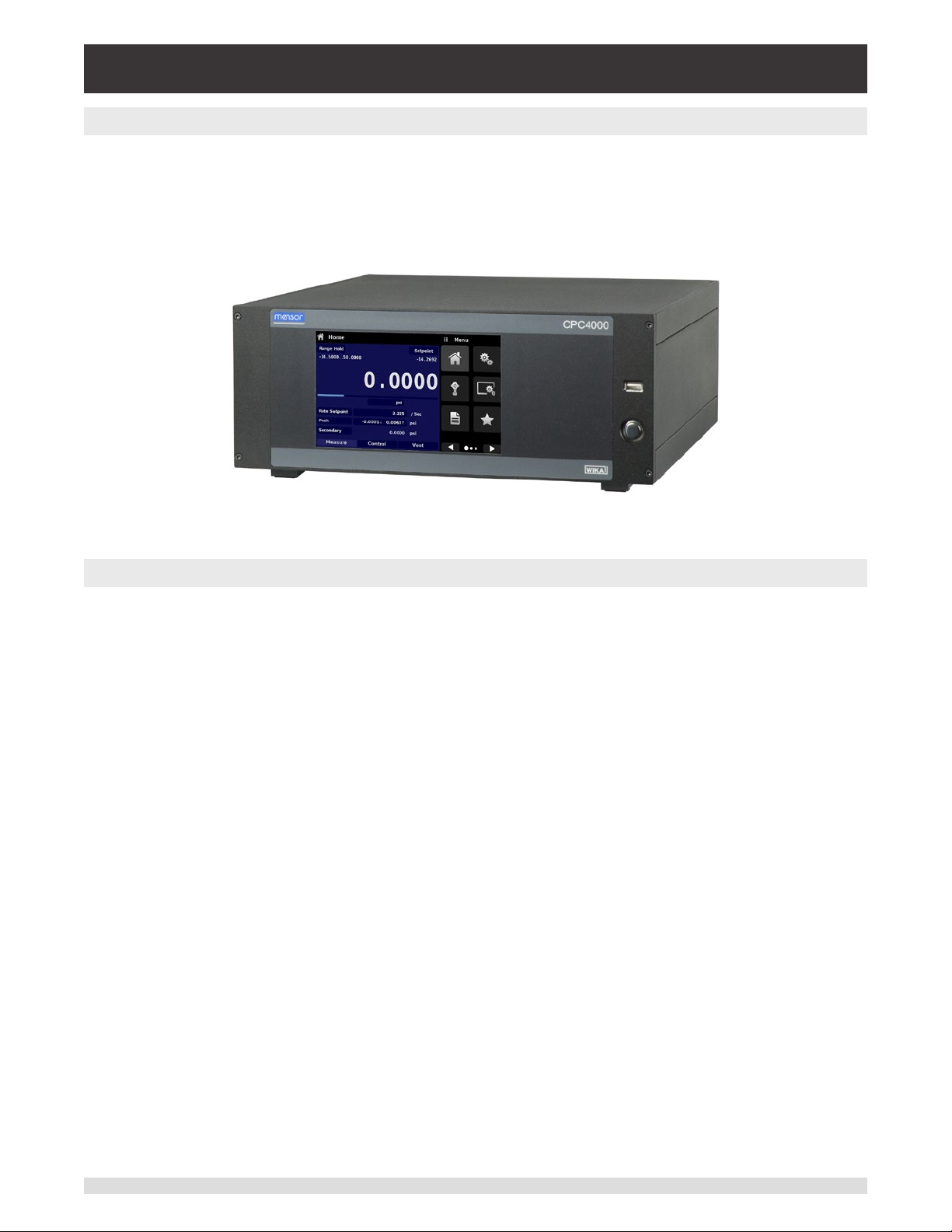
The CPC4000 Industrial Pressure Controller is a single-channel / multi-range automatic pressure controller designed to test and calibrate a variety of pressure devices such as pressure gauges, pressure
switches, sensors, transducers and transmitters in either absolute or gauge pressure modes. The
CPC4000 can have up to two highly stable precision transducers and an optional barometric reference.
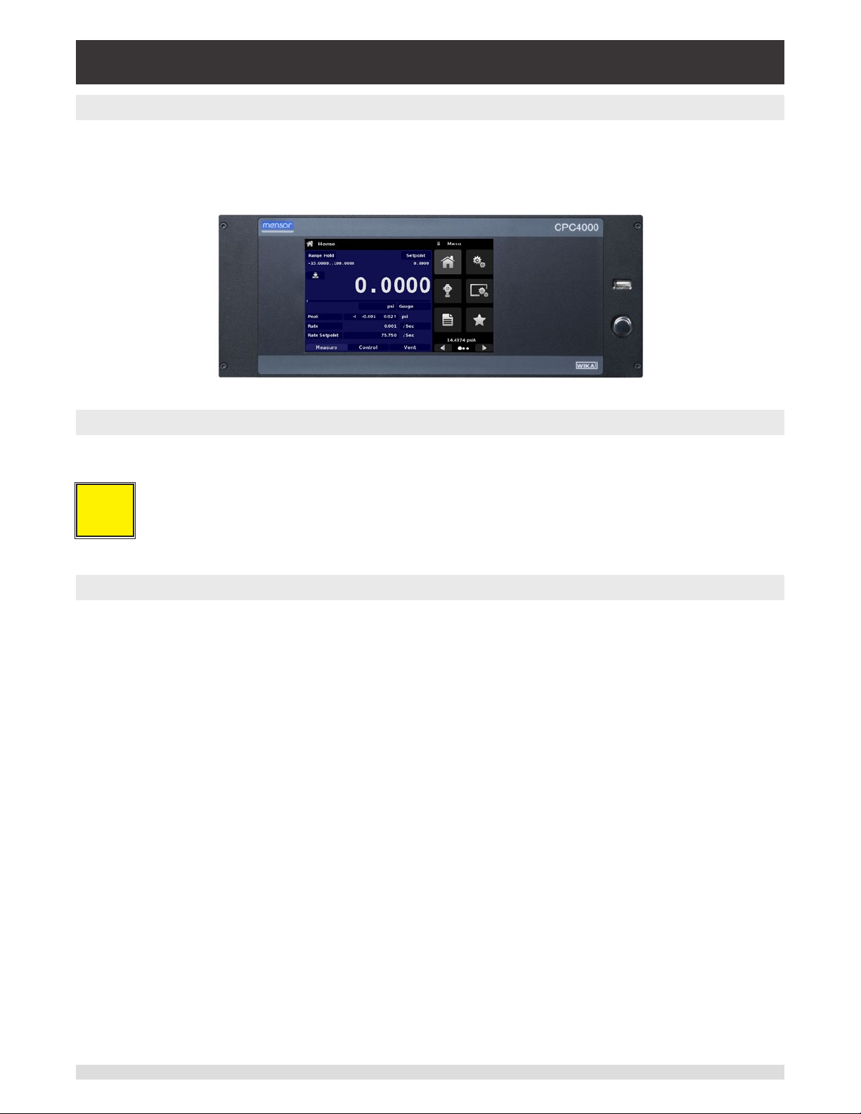
The CPC4000 is available as a desktop or a rack mountable instrument.
Figure 3.1 - Desk top version
3.1 Features
Here is a short list of signicant features designed into the CPC4000:
• Up to two highly stable, temperature compensated, internal pressure transducers.
• Broad operating pressure range from -15 … 3,045 psig/ -1 … 210 bar or 0 … 3,060 psia/ 0 … 211 bar
absolute.
• 0.02% Intelliscale-50 accuracy.
• An optional removable / interchangeable internal high accuracy barometric reference transducer
providing gauge pressure emulation for absolute ranges and absolute pressure emulation for gauge
ranges.
• Auto-ranging between the two pressure transducers to provide seamless transition between all
ranges.
• 7” Color LCD with touch screen.
• Leak test and burst test application.
• Multiple languages; change the language for on-screen text and number/date formats by simply
touching one of the “national ag” icons available in the setup screen.
• Desk top or rack mount
• Local operation, or command and read remotely.
12 Operating Instructions - CPC4000
Page 13

Industrial Pressure Controller
CPC4000
3.2 Turning On
You can conrm that your CPC4000 is operational right now. Apply power to the power connector on the
rear of the instrument with the included power cord, remove any plastic plugs from the rear panel pressure ports, and press the power switch to ON. The system will go through an initialization process, which
takes about 30 seconds, and then a display will appear similar to the screen shown below.
Power Switch
ON/OFF
Earth Ground! Any power adaptors or surge protection devices that negate the
!
Caution
protective earth ground should not be used. The power cord must be accessible
and contain a protective earth ground. Do not position the equipment so that it is
diculttoremovethepowercord.
Ventilation!Donotblockairowtoventilatingfanslocatedonrearofinstrument.
!
Caution
To see information about the conguration of your new CPC4000, touch the Next Page Button [ ]
then the Information Application (App) icon [ ] on the menu and a window will appear listing the
Mensor customer service contact, model number and the transducers that are installed. Press the
Previous Page Button [ ] then the Home App [ ] to return to the main screen.
Information Application
Operating Instructions - CPC4000 13
Page 14
Industrial Pressure Controller
CPC4000
3.3 Front Panel
The CPC4000 front panel includes a 7” color LCD with touch screen. Operator input is accomplished by
pressing the words or symbols and the App icons presented on the display. There is a single discrete on/
o button and a USB port on the right hand side. The front panel also shows the model number designation and brand logos.
3.3.1 Power Switch
The power switch is a two-state device with an action similar to that of a ball point pen. Push the button
with enough force to latch it in to turn the unit ON. Push it again to release it to turn the system OFF.
If power to the instrument is interrupted while ON it will shut down until the power is
i
Notice
3.3.2 USB Port
The front panel USB port acts like the Host USB and is intended for future expansion or software upgrades.
restored, then immediately resume operation.
14 Operating Instructions - CPC4000
Page 15

Industrial Pressure Controller
CPC4000
3.4 Display
The display is made up of two sections. In the main screen (“Home Application”), the left three fourths
shows the operating screen with the control channel. The control channel displays the active pressure
reading, units, mode (absolute or gauge), active range of the internal transducer, pressure control setpoint, a bar graph (if enabled), a zero or tare button (if enabled) and any auxiliary displays that have been
chosen. The right one fourth of the screen has Application Icons (“Apps”) for setting general instrument
settings, control settings, display settings, program settings, favorites plus a “Next Page” butt
that, when pressed, shows a second and third page of icons for information, troubleshooting, remote
communication, step setting, leak test, burst test and service applications.
Active transducer
range
Optional Zero or Tare
Current Value
Optional Bar graph
Units and Mode
on [ ]
Auxiliary Displays
{
Operating Modes
Operating Screen Settings Apps
Buttons, Labels and Windows: The CPC4000 touch screen has many buttons with relevant graphic
icons or text which, when pressed, will open a related window where changes can be made or information viewed. Some of these buttons will toggle from one state to another, others present choices or display a numerical data entry screen. Text or icons that are displayed, but do not respond to being touched,
are called labels or windows. Operators will quickly become accustomed to the particular characteristics
of the frequently used buttons.
Main Screen: The main screen or “Home Application”, appears after power-up. This screen contains the
operating screen and Settings application screen. It will remain as congured after a power cycle.
Operating screen: The operating screen (left 3/4 of the screen) contains information relevant to the
measurement. Up to three auxiliary displays can be shown simultaneously along with the current pressure value. The operating mode of the instrument can be selected and changed in this screen between
“Measure”, “Control” and “Vent”.
Operating Instructions - CPC4000 15
Page 16
Industrial Pressure Controller
CPC4000
3.5 Chassis Assembly
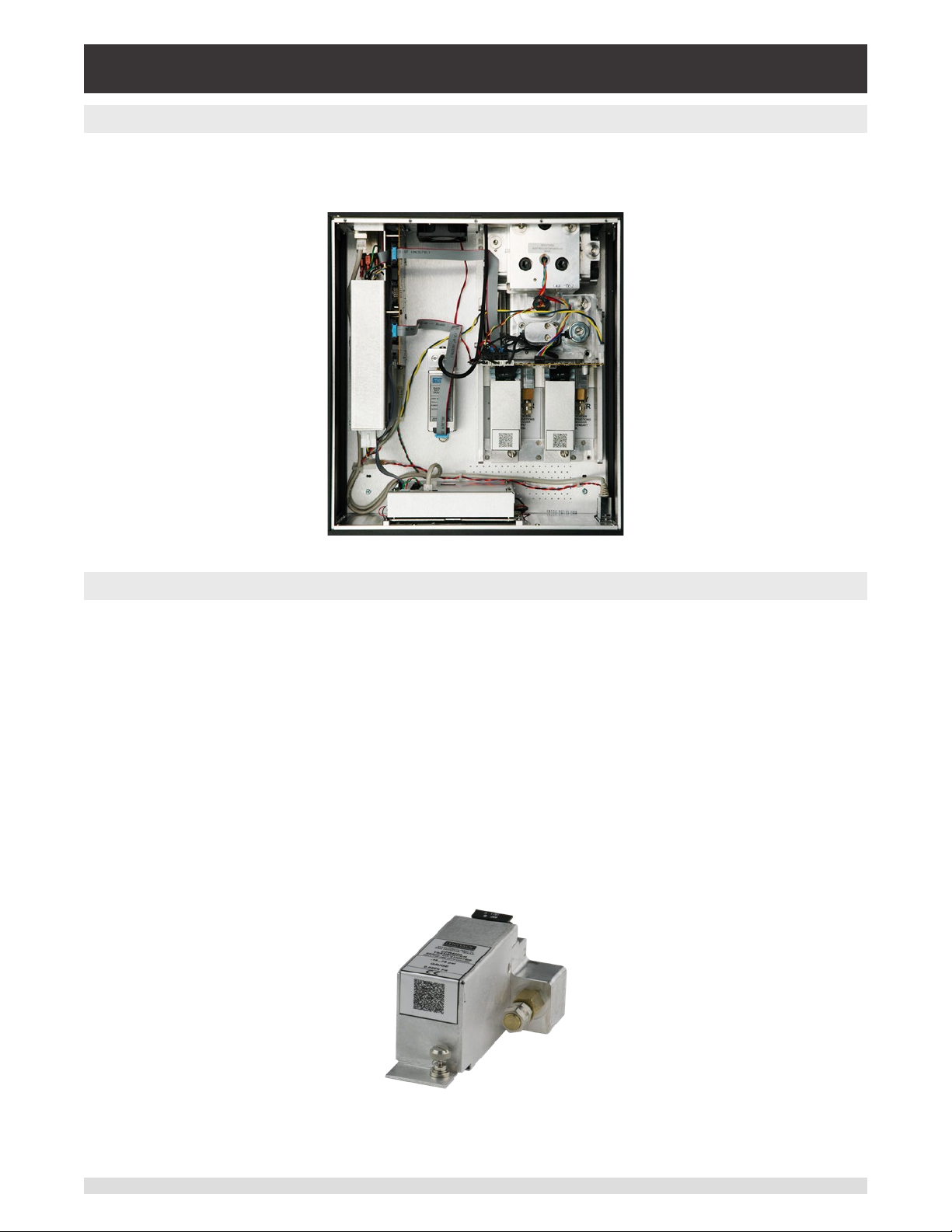
The chassis assembly is the housing for the system. The transducers are self-contained inside the chassis and can be replaced using basic hand tools. Figure 3.5 shows the top view of the chassis with the
cover removed.
Figure 3.5 – Chassis Assembly
3.5.1 Control Module
The control module is referred to as the “Solenoid Valve Regulator” (SVR Module). The SVR Module is
available in four variations depending on the working pressure range:
• Low Pressure SVR Module (LPSVR)
• Medium Pressure SVR Module (MPSVR)
• High Pressure SVR Module (HPSVR)
• Extra High Pressure SVR Module (EPSVR)
Pressure limits for all of these are specied in Section 4, Specications.
Each control module includes platforms for up to two high performance pressure transducers, CPR4000,
which are traceable to NIST standards. Both of these transducers can be used in conjunction with the
highly stable pressure regulator to produce a precise output. Each transducer includes its own on-board
compensation and calibration data so that any transducer can be replaced in the instrument without
requiring a recalibration.
Figure 3.5.1 – Pressure Transducer
16 Operating Instructions - CPC4000
Page 17
Industrial Pressure Controller
CPC4000
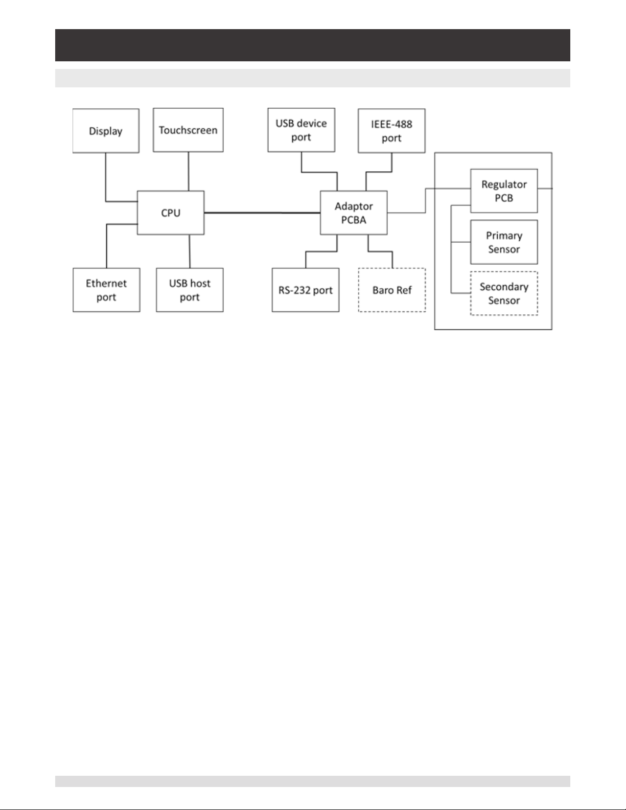
3.6 Electrical Block Diagram
Figure 3.6 – Electrical Block Diagram
Operating Instructions - CPC4000 17
Page 18

Industrial Pressure Controller
CPC4000
4 Specications
Accuracy specications presented herein are obtained by comparison with primary standards traceable
to a national metrology institute or recognized international standard organization. These specications
are obtained in accordance with the ISO Guide to the Expression of Uncertainty in Measurement (GUM).
The calibration program at Mensor is accredited by the American Association of Laboratory Accreditation
(A2LA) as complying with both the ISO/IEC 17025:2005 and the ANSI/NCSL Z540-1-1994 standards. If
there is an exception to the requirements and recommendations of Z540 during a calibration the excep-
tion is noted on the individual calibration certicate.
Mensor reserves the right to change specications without notice.
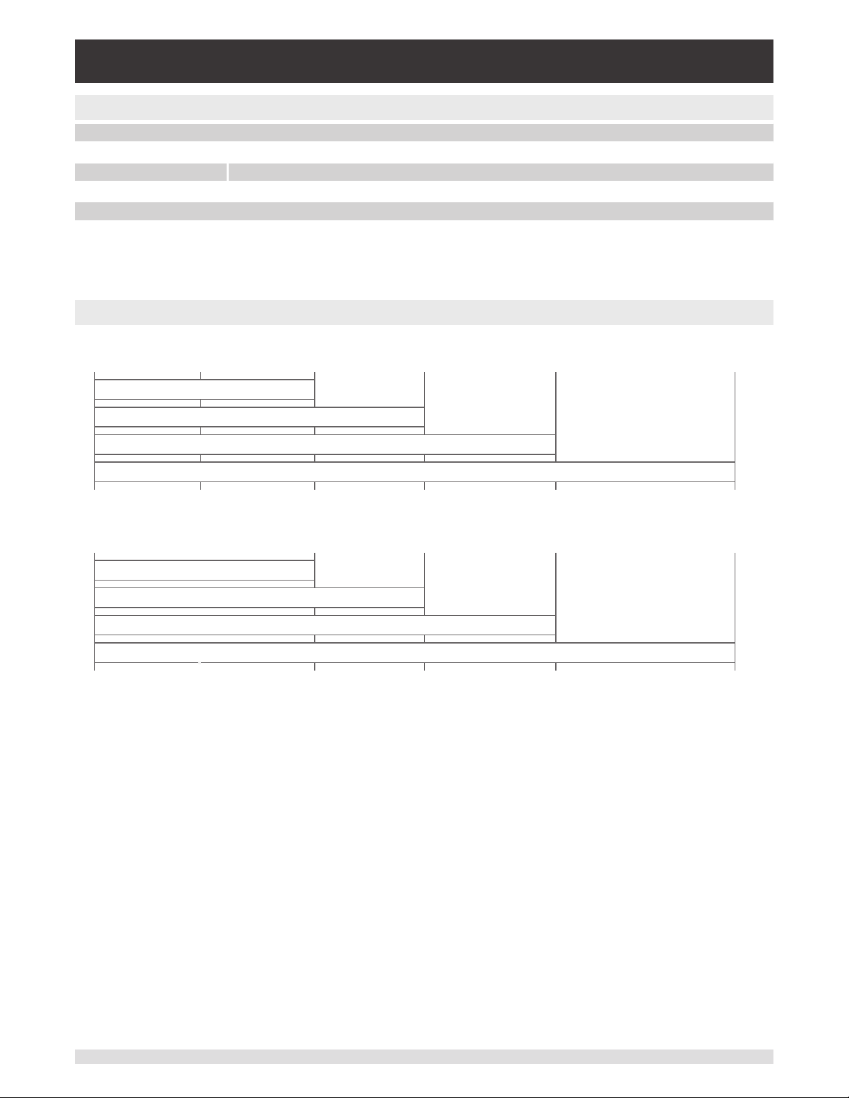
4.1 MeasureSpecication
Reference pressure transducer model CPR4000
Pressure range Standard Optional
Accuracy
Gauge pressure 0 ... 0.35 to 0 ... 210 bar
Bi-directional pressure -0.17 ... 0.17 to -1 ... 210 bar
Absolute pressure
Precision
Calibration interval 365 days 365 days
Optional barometric reference
Function The barometric reference can be used to switch pressure types 6), absolute <=> gauge. With gauge
Measuring range 8 …. 17 psi abs. (552 … 1,172 mbar abs.)
Pressure units 39 and two freely programmable
1) It is dened by the total measurement uncertainty, with the coverage factor (k = 2) and includes the intrinsic performance of the instrument, the measurement uncertainty of the reference
2) FS = full span
3) 0.02% IS-50 accuracy: Between 0 ... 50% of the full scale, the accuracy is 0.02% of half of the full scale value and between 50 ... 100% of the full scale, the accuracy is 0.02% of reading.
4) The minimum calibrated range of absolute transducer(s) is 600mTorr
5) It is dened as the combined eects of linearity, repeatability and hysteresis throughout the stated compensated temperature range
6) For a pressure type emulation, we recommend a native absolute pressure transducer, since the zero point drift can be eliminated through a zero point adjustment.
(1)
4)
5)
instrument, long-term stability, inuence of ambient conditions, drift and temperature eects over the compensated range with recommended zero point adjustment every 30 days.
0.02% FS
(0 ... 5 to 0 ... 3,045 psi)
(-2.5 ... 2.5 to -15 ... 3,045 psi)
0 ... 1 to 0 ... 211 bar abs.
(0 ... 15 to 0 ... 3,060 psi abs.)
0.008% FS 0.008% FS
pressure transducers the measuring range of the transducers must begin with -15 psi (-1 bar) in order to
carry out a complete absolute pressure emulation
2)
0.02% IS-50
0 ... 1 to 0 ... 210 bar
(0 ... 15 to 0 ... 3,045 psi)
-1 ... 10 to -1 ... 210 bar
(-15 ... 145 to -15 ... 3,045 psi)
0 ... 1 to 0 ... 211 bar abs.
(0 ... 15 to 0 ... 3,060 psi abs.)
3)
18 Operating Instructions - CPC4000
Page 19

Industrial Pressure Controller
CPC4000
4.2 Base Instrument
Instrument
Instrument version Standard: desktop case
Dimensions See technical drawings
Weight approx. 127 kg (28 lbs) with all internal options
Warm-up time approx. 15 min
Display
Screen 7.0” color LCD with resistive touchscreen
Resolution 4 … 6 digits depending on range and units
Connections
Pressure connections 4 ports with 7/16”- 20 F SAE, 1 port with 1/8” F NPT and 1 port with 10-32 UNF female
Filter elements The instrument has a 40-micron lters on all pressure ports.
Pressure port adapters Standard: without
Barometer port adaptors Standard: barb tting
Permissible pressure media Dry, clean air or nitrogen (ISO8573-1:2010 Class 5.5.4 or better)
Wetted parts Aluminum, brass, 316 and 316L stainless steel, Buna N, FKM/FPM, PCTFE, PEEK, PTFE, PPS,
Overpressure protection Safety relief valve xed to reference pressure transducer and adjusted to specic measuring range
Permissible pressure
Supply port 110% FS or 0.69 bar (10 psi), whichever is greater
Measure/Control port max. 105 % FS
Voltage supply
Power supply AC 100 ... 120 V, 50/60 Hz; AC 220 ... 240 V, 50/60 Hz
Power consumption max. 150 VA
Permissible ambient conditions
Storage temperature -20 ... 70 °C (-4 ... 158 °F)
Humidity 5 … 95 % r. h. (relative humidity, non-condensing)
Compensated temperature range 15 … 45 °C (59 ... 113 °F)
Mounting position horizontal
Control parameter
Control stability < 0.005% FS of the primary range, in precision mode
Control mode precision, high speed and custom
Control time 10 s (regarding a 10% FS pressure increase above atm. in a 50 ml test volume, in high speed mode)
Control range 0 ... 100% FS
Minimum control pressure 0.0017 bar (0.025 psi) over exhaust pressure or 0.05% FS whichever is greater
Overshoots < 1% FS in high speed control mode (typical <0.1% FS in precision control mode)
Test volume 50 ... 1,000 ccm
Communication
Interface Standard: Ethernet, IEEE-488, USB, RS-232.
Command sets Mensor, WIKA SCPI, others optional
Response time approx. 100 ms
Internal program up to 24 sequences of 99 steps each
Option: 19” rack-mounting kit
Option:
6 mm tube tting, 1/4” tube tting, 1/4” female NPT ttings, 1/8” female NPT ttings or 1/8” female
BSP ttings
Option: 6mm tube tting, 1/4“ tube tting
glass-lled epoxy, RTV, ceramic, silicone, silicone grease, Urethane
Operating Instructions - CPC4000 19
Page 20
Industrial Pressure Controller
CPC4000
4.3 ApprovalsandCerticates
EC declaration of conformity
EMC directive
Low voltage directive EN 61010-1
RoHS directive 2011/65/EU, article 4
Certicate
Calibration
7) Warning! This is class A equipment for emissions and is intended for use in industrial environments. In other environments, e.g. residential or commercial installations, it can intefere with
other equipment under certain conditions. In such circumstances the operator is expected to take the appropriate measures.
8) Calibration in a horizontal position/operating position.
4.4 Working Ranges of the Controller Modules
7)
8)
EN 61326-1 emission (group 1, class A) and interference immunity (industrial application)
Standard: A2LA calibration certicate (standard on factory)
Option: DKD/DAkkS calibration certicate
Bi-directional or gauge pressure [bar (psi)]
1)
-1 (-15) 0 3.4 (50) 10 (150) 100 (1,500) 210 (3,045)
LPSVR MODULE ±0.17 bar (±2.5 psi)
MPSVR MODULE ±0.35 bar (±5 psi)
HPSVR MODULE -1 ... 5 bar (-15 ... +75 psi)
Absolute pressure [bar (psi)]
2)
2)
2)
EPSVR MODULE -1 ... 10 bar (-15 ... +150 psi)
1)
2)
0 4.4 (65) 11 (165) 101 (1,515) 211 (3,060)
LPSVR MODULE 0 ... 1 bar (0 ... 15 psi)
MPSVR MODULE 0 ... 1 bar (0 ... 15 psi)
HPSVR MODULE 0 ... 6 bar (0 ... +90 psi)
1) Mixing of absolute pressure and gauge pressure transducers in a module is not possible.
2) Smallest acceptable transducer range
For controlling absolute pressure a vacuum pump connected at the exhaust port is required.
2)
2)
2)
EPSVR MODULE 0 ... 11 bar (0 ... 165 psi)
2)
20 Operating Instructions - CPC4000
Page 21

Industrial Pressure Controller
CPC4000
5 Installation
!
Warning
5.1 Unpacking the Instrument
In addition to functional testing, each unit is inspected for appearance prior to leaving the factory. Upon
receipt, please examine the instrument for shipping damage. Report any apparent damage to the carrier
immediately.
In addition to this manual you should have:
• CPC4000 Industrial Pressure Controller
• Power Cord
• Fitting adapters ordered
• Any accessories ordered
• An envelope containing the calibration certicate(s)
• A Quick Start Guide for all Mensor products
• A USB drive containing all Mensor manuals
WARNING: READ THESE INSTRUCTIONS BEFORE INSTALLATION!
Operating Instructions - CPC4000 21
Page 22
Industrial Pressure Controller
CPC4000
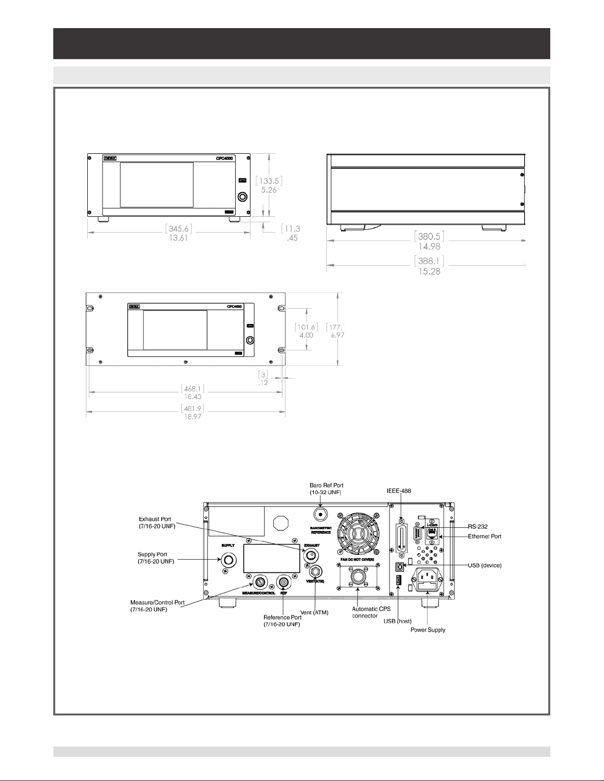
5.2 Dimensions (mm)/ inches
Front view Side view
19” rack mount
Rear Panel
22 Operating Instructions - CPC4000
Page 23
Industrial Pressure Controller
CPC4000
5.3 Mounting
The instrument can be set up on a desk top or it can be rack-mounted. Rack mount hardware is optional
on the CPC4000 (see Section 5.2 Dimensions and Section 8, Options).
The special transducers used in the CPC4000 are relatively insensitive to tilt and vibration. However to
further assure stability and accuracy, avoid mounting the instrument on surfaces subject to excessive motor or machinery vibration.
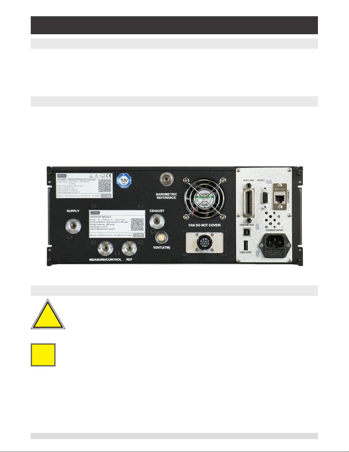
5.4 Rear Panel
Five pneumatic pressure ports are located across the rear panel. Any instrument containing sub-atmospheric pressure ranges needs a vacuum pump to be connected at the exhaust port. The instruments
with pressures above or at atmospheric pressures will have the exhaust port open. Next to the ventilation
fan is a 10-32 UNF tting which is connected to the barometric reference if installed. Below the ventilation
fan is the connection to drive the automatic contamination prevention system. Positioned on the right side
is a remote communication connections; RS-232, Ethernet, IEEE- 488, USB along with the USB host
connection.
Figure 5.4 A – Rear Panel
5.4.1 Pressure Connections
Warning! The pressure connections must be installed according to the following
instructions, observing the relevant regulations. The installation is to be per-
!
Warning
formed by trained, authorized personnel, knowledgeable in the safety regulations
for working on pneumatic/hydraulic systems.
Five pressure connections are on the rear panel. Plugged connections are not used.
i
Notice
All pressure ports on the rear apart from the Vent Port are female 7/16 - 20 SAE/MS straight threads per
MS16142 and SAE J514 table 14. Connected adaptors require a tube tting boss seal with an o-ring per
MS33656. Mensor can provide a variety of adapter ttings (see Section 8 Options) with the instrument.
Do not use sealant on ttings sealed with an o-ring. The integrity of each seal is particularly important
since even microscopic leaks can cause errors in pressure measurements.
Operating Instructions - CPC4000 23
Page 24

Industrial Pressure Controller
CPC4000
5.4.2 Supply Port
The pressure supplied to the pressure connection labeled “Supply” should be approximately 10% higher
than the full scale of the highest pressure transducer installed in the controller or 10 psi, whichever is
greater (see section 6.2.1).
5.4.3 Exhaust Port
The pressure connection labeled “Exhaust” is for the vacuum supply. In a gauge pressure version it can
be left open to atmospheric pressure.
5.4.4 Vent Port
The pressure connection labeled “Vent” is the exhaust port where the system pressure is vented to the
atmosphere under certain conditions. This port has a breather vent installed that acts like a muer. Leave
this port open.
5.4.5 Measure/Control Port
The Measure/ Control port (when in the Control mode) supplies pressure that is precisely controlled by
the controller. In the Measure mode, a pressure applied to the Measure/Control port is measured by the
internal transducers.
5.4.6 Reference Port
The pressure connection labeled “Reference” is the reference port, it is available to connect to the reference side of the transducer. This port is normally left open to atmosphere but may be connected to a
stable reference pressure. In an absolute pressure transducer this port is not used.
5.4.7 Barometric Reference Port
The Barometric Reference port is connected to the optional internal barometer and should be left open to
atmospheric pressure.
5.5 Remote Communication Connections
See Section 7, Remote Operation, for connections and commands for operation over IEEE-488, Ethernet, USB or RS-232 ports.
5.6 Power Up
Apply power to the power connector on the rear of the instrument using the power cord included, and
switch the power switch on the front of the unit ON. The instrument will go through an initialization process and system check. As soon as the system check is completed the system will default to a screen
similar to the one shown in Section 6.1.2 - Display Screen Features. The main screen may be congured
in many dierent ways but initially it will be in a default conguration. Subsequently, the unit will power
up in the conguration that it was in when last powered o. Allow at least 15 minutes of warm up before
performing critical pressure measurements.
Donotpositiontheequipmentsothatitisdiculttoremovethepowercord.Theinstrument
is not intended for connection of long-distance lines, i.e. lines within a building that are longer
than 30 m, or that leave the building (including lines of outdoor installations).
24 Operating Instructions - CPC4000
Page 25

Industrial Pressure Controller
CPC4000
6 Local Operation and Setup
6.1 General Operation
This section describes the procedures for operating the CPC4000 from the front panel. Instructions for
operating the device remotely from an external computer are covered in Section 7, Remote Operation. By
following the procedures provided in these two sections and Section 10, Calibration, you can expect your
CPC4000 to deliver maximum accuracy and dependability for many years of useful service.
6.1.1 Setup Applications
Conguration of the CPC4000 is achieved by changing settings accessed through the Application (“App”)
buttons. Local operation is accomplished by observing the data presented in the display. The appearance
and functionality of the display can be changed by pressing the App button for the related function. After
an app has been chosen, a set of related parameters will appear. After choosing one of these parameters, a set of selections related to that parameter will appear or a data entry keypad.
The desired selection or data can be entered here.
6.1.2 Display Screen Features
The screen shown below provides an overview of the features shown on the display after initialization.
The left three fourths of the display contains the area where information is displayed (in this case the
Home Application) and the right one fourth contains the selection icons for each application. A zero or
tare button, bar graph and auxiliary displays (Peak, Rate, Rate Setpoint, Uncertainty, Units or Barometer)
will appear in the Home App if activated. All of the CPC4000 screen features are described in more detail
throughout this manual. The active App is represented in a lighter gray color as compared to the other
Apps.
Active transducer
range
Optional Zero or Tare
Current Value
Optional Bar graph
Units / Pressure Type
Auxiliary Displays
Operating Modes
{
Operating Screen Settings Apps
Figure 6.1.2 – Display Screen Features
Operating Instructions - CPC4000 25
Page 26
Industrial Pressure Controller
CPC4000
6.2 Initial Setup
Section 6.2.1 and 6.2.2 are provided rst so that the operator can initially check the information screen to
verify the installed components and to change the language if needed.
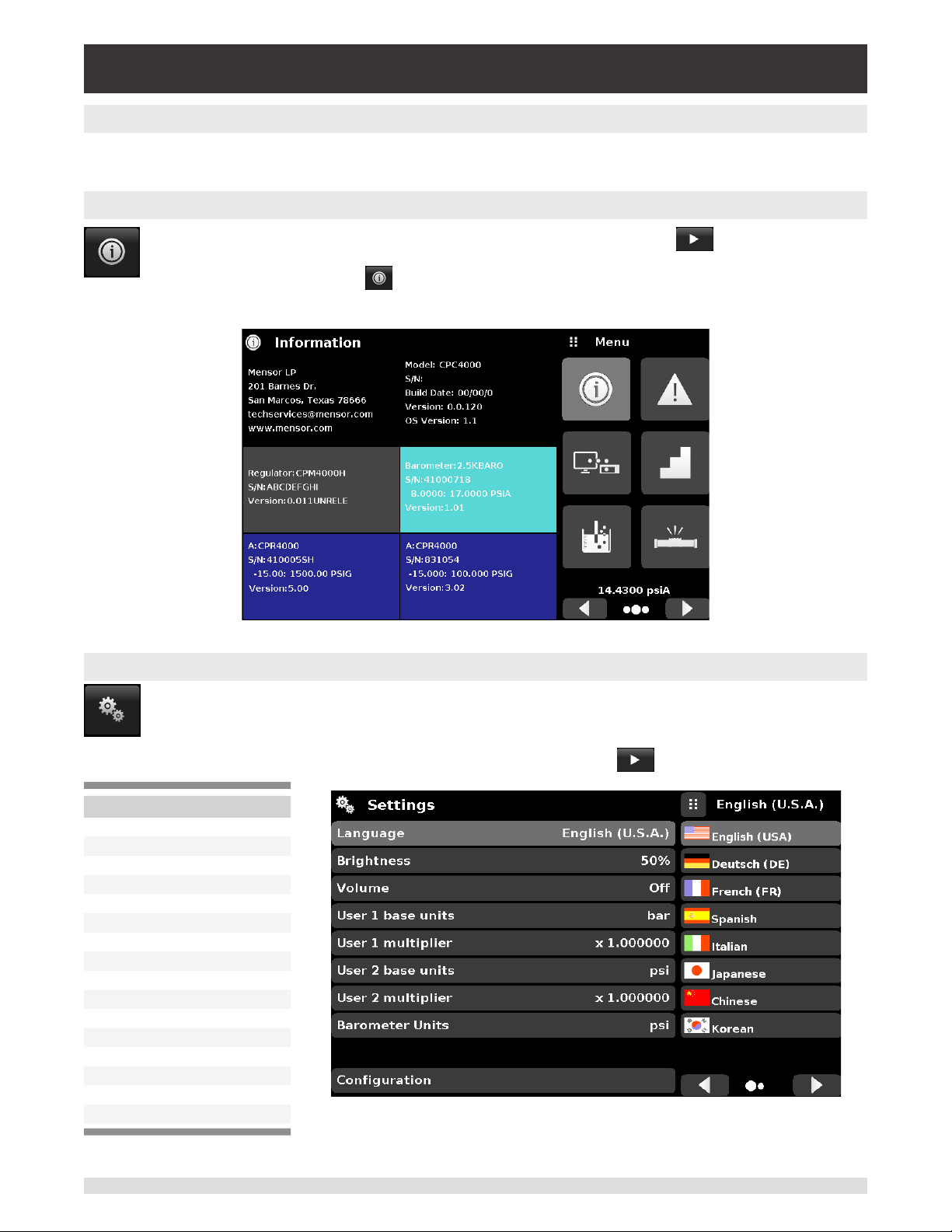
6.2.1 Contact and Version Information Application
Navigate to the App selection area by pressing the Next Page button [ ] at the right bottom
under the App buttons. This gives access to the second page of the App selection area. Press
the Information App button [ ] to display Mensor contact, installed transducers, installed
regulator along with instrument and software version information.
6.2.2 Language Selection
Pressing the settings application button will open a screen where the language, display bright-
ness, volume, user base units/multiplier and conguration loading/saving, can be changed. The
current language selections available are shown in the table below. Additional language choices
will appear on the screen after pushing the Next Page button [ ]:
Language Country
English USA
German Germany
French France
Spanish Spain
Italian Italy
Chinese China
English Great Britain
German Switzerland
French Switzerland
Spanish Mexico
Russian Russia
Korean Korea
English Canada
French Canada
Polish Poland
Japanese Japan
Figure 6.2.1 – Information
26 Operating Instructions - CPC4000
Page 27
Industrial Pressure Controller
CPC4000
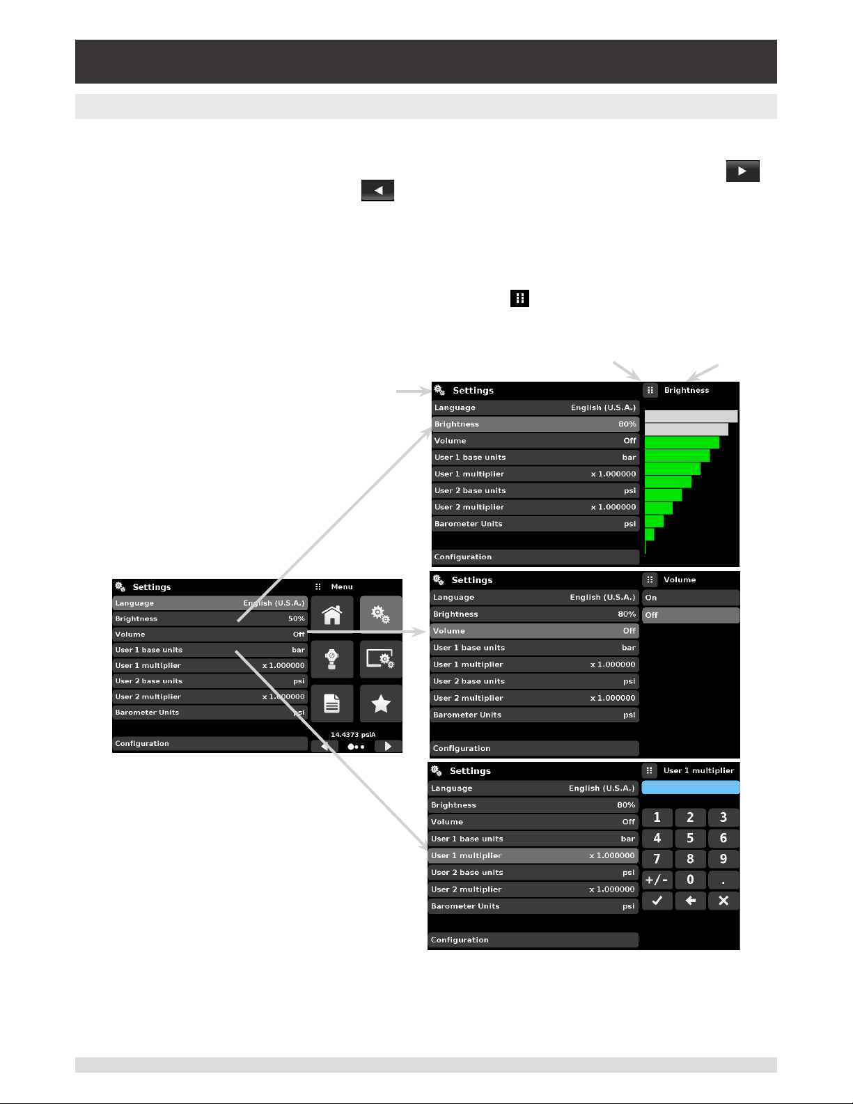
6.3 Application Selection and Parameter Inputs
The application selection/input area on the right one fourth of the screen (see Figure 6.1.2 - Display
Screen Features) is the area where setup, information, calibration, service and other Apps can be chosen. Multiple pages of application selections can be accessed by pressing the Next Page button [
] or by pressing the Previous Page button [ ]. A series of horizontally placed circles on the bottom
right represents the number of pages and indicate the active page by a larger circle. As each App is chosen, related application parameters will appear on the left three fourths of the screen along with the name
of the application, and a reduced size icon in the top title section. When a parameter is chosen, related
selections, sliding scales or a data entry key pad will appear in the input area on the right where the application selection buttons were previously displayed. An example of each type of input is shown below. To
return to the App selection menu, simply press the Menu button [ ] above the input area. The purpose
and use of each selection and menu is intuitively apparent and will become second nature with minimal
exposure to the menu structure.
App Title
Menu Button
Input Title
Operating Instructions - CPC4000 27
Page 28
Industrial Pressure Controller
CPC4000
6.4 Applications
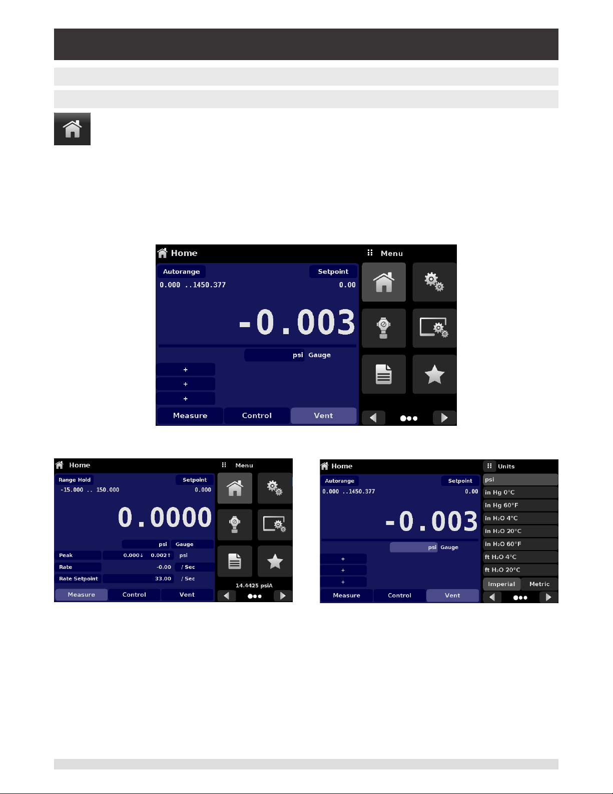
6.4.1 Home Application
The Home App is the normal operation screen. This application is dierent from the others in
that it is not used to setup the conguration but is used to monitor the pressure applied to the
installed transducers and the device under test through the measure / control port.
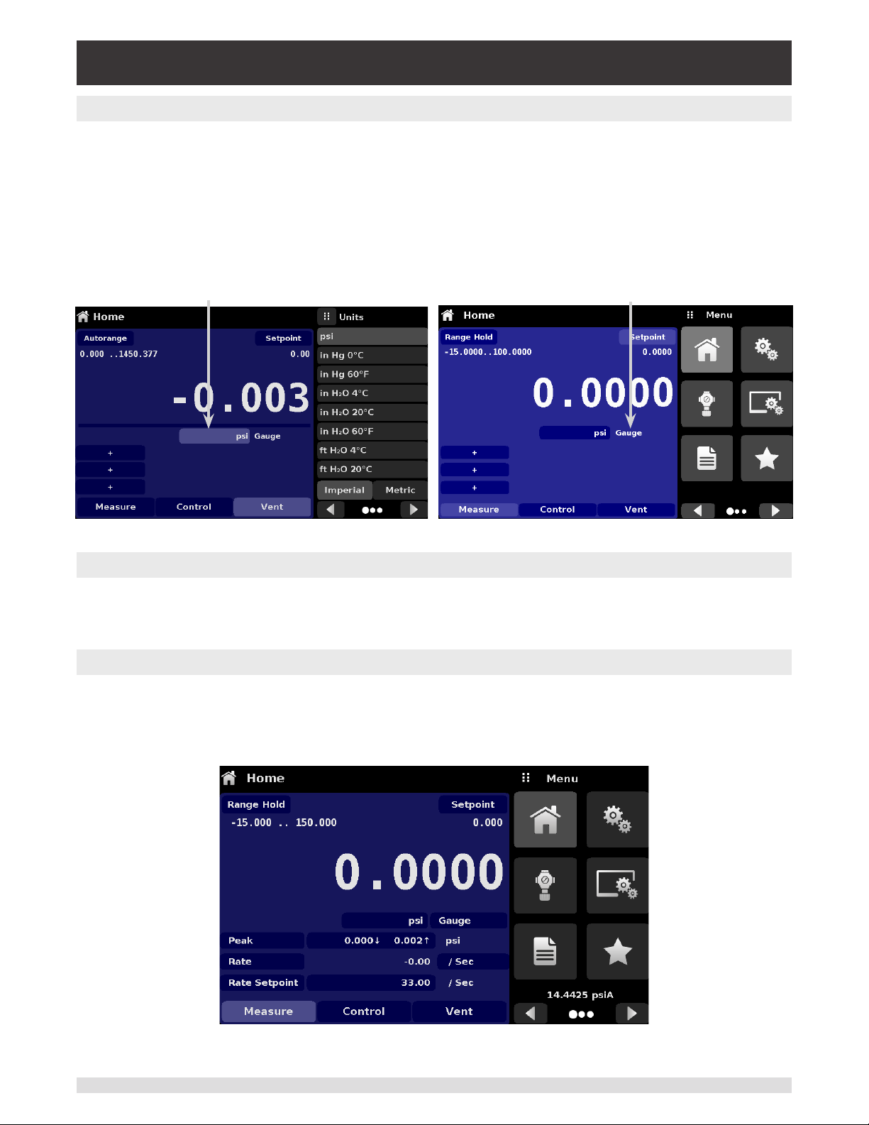
The screen in gure 6.4.1-A shows the basic Home App in an instrument. The user can change the
display to show multiple auxiliary displays by pressing the auxiliary button on the left corner of the screen
(gure 6.4.1-B). The Units button is always displayed. When the Units button is pressed a selection of
imperial and metric units will be displayed on the right (gure 6.4.1-C); notice that the Units button has a
lighter background when the selection menu is active. If a barometric reference is installed, the Mode button, described below, will toggle from Gauge to Absolute mode when pressed.
Figure 6.4.1-A – Basic Home App
Figure 6.4.1-B – Single Channel Display Figure 6.4.1-C – Pressure Units
28 Operating Instructions - CPC4000
Page 29
Industrial Pressure Controller
CPC4000
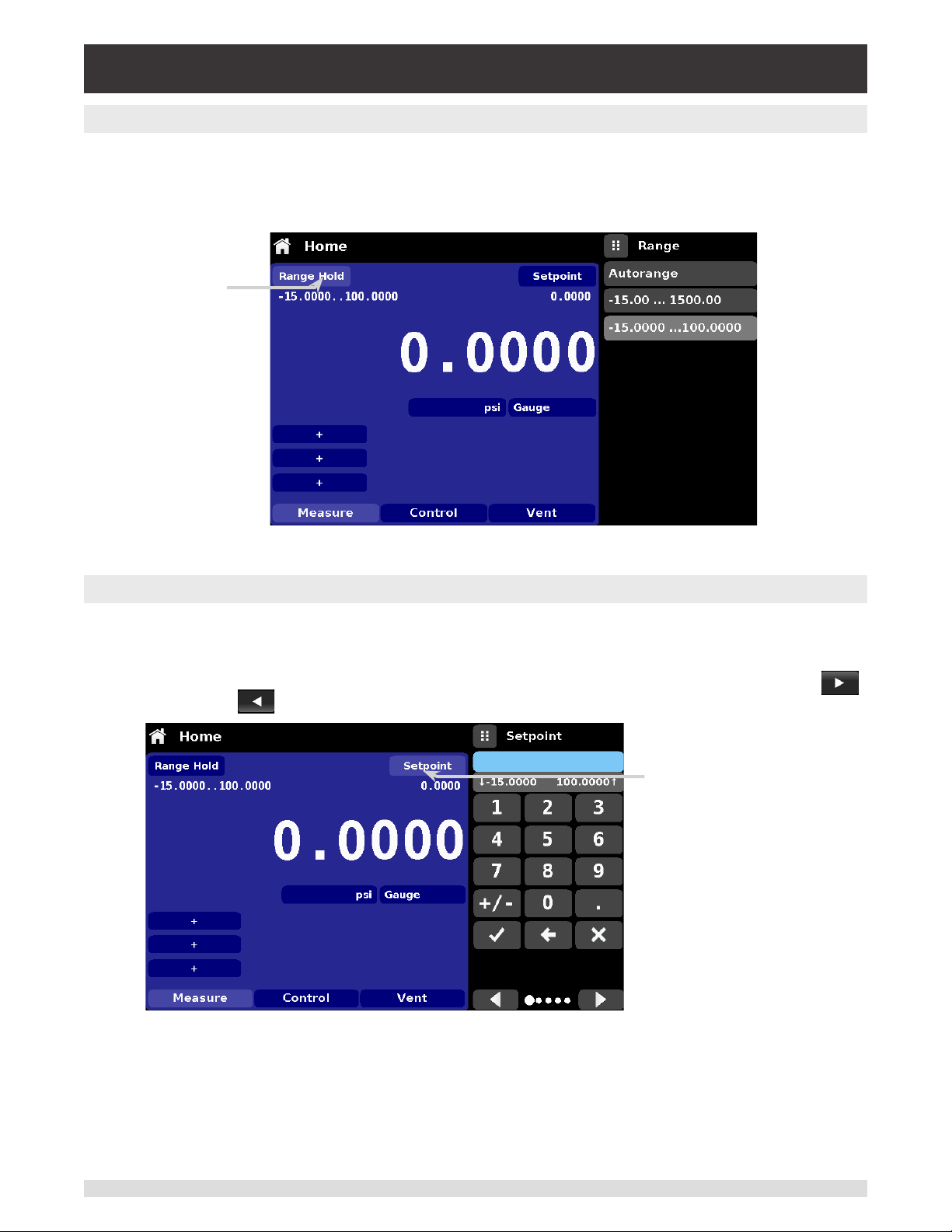
6.4.1.1 Range Hold / Autorange
The Range Hold / Autorange button allows the user to select the active range. By clicking the Range Hold
button, the user can select the active transducer from the primary and secondary transducers or utilize
the “Autorange” feature to let the instrument automatically select the active range based on the current
pressure value.
Range Hold button
Figure 6.4.1.1 – Mode Label
6.4.1.2 Control Setpoint
The Setpoint button allows the user to enter the desired pressure value to be controlled by the instrument. There are multiple ways of entering the control setpoint: numeric keypad, step increments, percentage entry, digital step or a program data entry. These methods can be accessed by the user by pressing
the “Setpoint” button and the various setpoint entry methods can be navigated with the Next Page [ ]
and Previous Page [ ] buttons.
Setpoint button
Figure 6.4.1.2 – Setpoint Button
Operating Instructions - CPC4000 29
Page 30
Industrial Pressure Controller
CPC4000
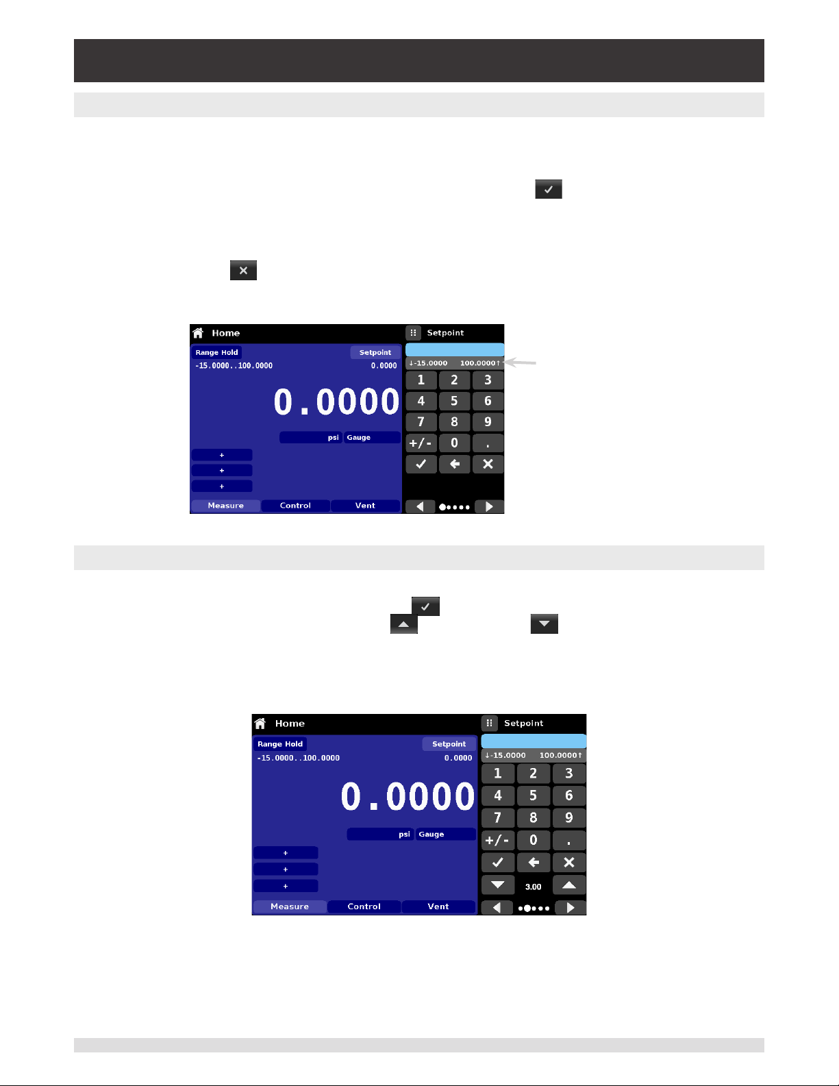
6.4.1.2.1 Numeric Keypad
The rst entry method provides 10 digits for numeric entry, plus the decimal point and a sign key (gure
6.4.1.2.1). The sign key [+/-] will toggle between positive and negative values. Each stroke on the key pad
will echo in the blue input value window above the pad. A change between plus and minus values [+/-]
can be entered at any time during the string entry. Pressing the Enter [ ] button will accept the value
and it will become the setpoint.
If the input window holds an illegal value when the Enter button is pressed the system will respond with
an error tone and the entry will turn red. When that happens determine the cause of rejection, delete the
entry using the Delete [ ] button and then enter a valid number. The setpoint can only be entered
within the minimum and maximum control range set in the Control Settings App (section 6.4.3.5). These
limits are shown above the numeric entry keypad.
Min & Max
setpoint values
Figure 6.4.1.2.1 – Numeric Keypad Setpoint Entry
6.4.1.2.2 Step Increments
The second entry method allows the user to enter the setpoint in the same way as the Numeric Keypad
by keying in the value and then pressing the Enter [ ] button. The user can then enter the desired
value of step increment and press the Step Up [ ] or Step Down [ ] button, without pressing the
Enter button. This number will then be used to decrease or increase the existing setpoint value. Subsequent touches of the Step Up or Step Down button will continue to increase or decrease the setpoint by
the step value. If the Enter button is pressed the newly entered value will register as a new setpoint value
on the Home Screen rather than a step value.
Figure 6.4.1.2.2 – Numeric Keypad with Step Increments
30 Operating Instructions - CPC4000
Page 31

Industrial Pressure Controller
CPC4000
6.4.1.2.3 Percentage Entry
The third entry method is the Percentage Entry method (gure 6.4.1.2.3-A) which allows the user to
select a setpoint value as a percentage of the pressure range of device under test (DUT). The user can
choose between various percentage values by clicking on the desired button. The setpoint will instantly
change to the selected percentage value of the DUT. Alternatively, the setpoint can also be selected as a
specic pressure value within the range of the DUT. The user can also congure the minimum and maximum pressure values of DUT by clicking the button displaying pressure range (gure 6.4.1.2.3-B). This
would take the user to the Step Settings App (gure 6.4.1.2.3-C) which is explained in Section 6.4.10,
Step Settings.
Figure 6.4.1.2.3-A – DUT Percentage Entry Figure 6.4.1.2.3-B – DUT Pressure Value Entry
Figure 6.4.1.2.3-C - Step Settings App
Operating Instructions - CPC4000 31
Page 32

Industrial Pressure Controller
CPC4000
6.4.1.2.4 Digital Step Entry
The fourth entry method is the Digital Step data entry method. This method allows the user to increase or
decrease the setpoint value by one digit at a time. The digit to be changed can be selected from a string
of ve zeroes (0) and one blue numeral one (1) by sliding a nger across the zeroes and converting the
desired digit to a blue 1. The right most digit in the Digital Step corresponds to the least signicant digit of
the setpoint. Each digit of the setpoint can then be increased or decreased by pressing the Up [ ] or
Down [ ] button.
Figure 6.4.1.2.4 – Digital Step Entry
6.4.1.2.5 Program Data Entry
The fth entry method is through the automated Programs stored in the CPC4000 memory. The Program
Player allows the user to select one of the stored Programs and use it for setpoint entry. A Program can
be chosen either by using the Up [ ] or Down [ ] buttons or by clicking the program name. After
selecting the desired program, press the Play [ ] button to start the program. More information on
the Program Player and how to create/ edit programs is available in section 6.4.5, Programs Application.
Figure 6.4.1.2.5-A - Program Selection Figure 6.4.1.2.5-B – Program Data Entry
32 Operating Instructions - CPC4000
Page 33
Industrial Pressure Controller
CPC4000
6.4.1.3 Units and Pressure Type
The Units button is always displayed. When the Units button is pressed a selection of imperial and metric
units will be displayed on the right (gure 6.4.1.3 - A).The Pressure Type button is only active if there is
an optional barometer installed. Otherwise, the Pressure Type button becomes a label (gure 6.4.1.3 – B)
indicating the native pressure type of the channel (absolute or gauge). When an optional barometer is
installed, a native gauge transducer can emulate absolute pressure using the barometric reference. Alternatively, a native absolute transducer can emulate gauge pressure. Emulation can be activated simply by
pressing the Pressure Type button. The Pressure Type button becomes a label when the selected pressure unit is “% of F.S. value”.
Pressure Units button
Pressure Type button
Figure 6.4.1.3-A Figure 6.4.1.3-B
6.4.1.4 Bar Graph
An optional bar graph can be displayed below the current pressure value. The bar graph indicates the
position of the current value with the maximum range of the primary transducer in that channel. This bar
graph will appear in the Home App when selected from the Display Settings App (section 6.4.4).
6.4.1.5 Auxiliary Displays
The screen in gure 6.4.1.5 - A shows all of the possible auxiliary display items that can be included in
the Home App. The Home App can have up to three auxiliary displays which can be chosen by clicking
on each button and then selecting the display item from the menu on the right side of the screen (gure
6.4.1.5-B).
Figure 6.4.1.5-A – Home App with Auxiliary Displays
Operating Instructions - CPC4000 33
Page 34

Industrial Pressure Controller
CPC4000
Figure 6.4.1.5-B – Auxiliary Display Selection
Each auxiliary display can be modied by pressing the displayed button.
Peak: Pressing the Peak button will reset the upper and lower peak value to the current reading, subsequent negative or positive divergence from that reading will be recorded in the button.
Rate: Pressing the Rate button will display a choice of time rate units for the rate denominator.
Rate Setpoint: Pressing the Rate Setpoint button will let the user enter the new Rate Setpoint via mul-
tiple entry methods
Uncertainty: Displays the accuracy in current units at the pressure being displayed.
Units: Pressing the Auxiliary Units button will display the same set of units available for the primary units.
Pressing any of these units will change the auxiliary units to that chosen unit.
Barometer: Displays the reading of the optional barometric reference in current pressure units
34 Operating Instructions - CPC4000
Page 35
Industrial Pressure Controller
CPC4000
6.4.1.6 Zero Button
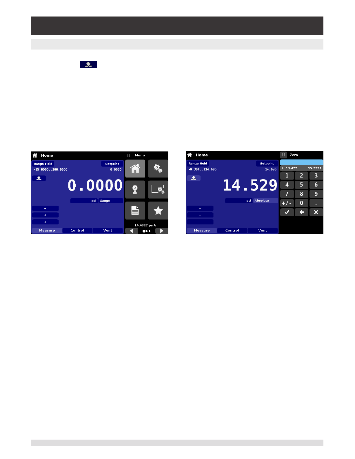
If the Zero Calibration function has been chosen in the Display Settings App (section 6.4.4), then the
Zero Cal Button [ ] will appear in the Home App. If the instrument is measuring absolute pressure,
and the Zero Cal Button is pressed, a keyboard will appear to allow a single point calibration. If the instrument is measuring gauge pressure, pressing the button will set the current reading to zero. If the instrument is in emulation mode (absolute or gauge) then the value will not be saved to the transducer but only
as a temporary adjustment while in emulation mode. After exiting the emulation mode or after a power
cycle, the temporary adjustment will be cleared. The zero adjustment not in emulation mode will be saved
to the transducer as if single point calibration had been performed.
Figure 6.4.1.6 shows the instrument with zero cal function enabled. The screen on the left shows instrument in gauge mode. The screen on the right shows the same instrument, but the zero button on the
absolute mode has been pressed, showing the keypad enabled to accept a new single point calibration
value.
Figure 6.4.1.6 – Zero Button, Gauge - Absolute
The background color of the zero button will momentarily change to a lighter color as the zero calibration
is performed then will revert back to a darker color when complete.
Operating Instructions - CPC4000 35
Page 36
Industrial Pressure Controller
CPC4000
6.4.1.7 Tare Button
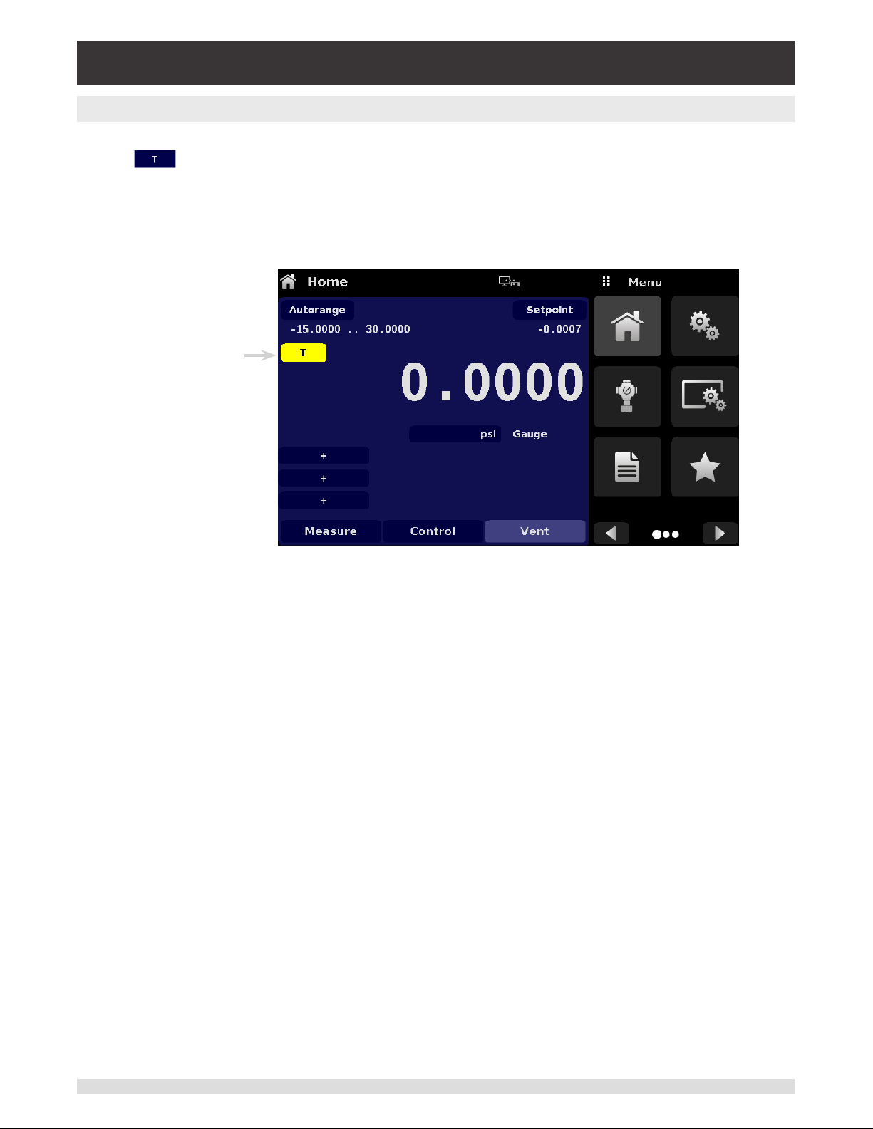
If the Tare calibration function has been chosen in the Display Settings App (section 6.4.4), then the Tare
Button [ ] will appear in the channel screen. For safety reasons, the tare button will be highlighted
in yellow when active. The Tare button and the Zero Button cannot appear on the screen at the same
time. When the Tare button is pressed, the instrument will subtract the current pressure reading (the tare
pressure) so that the indicator will display zero. Subsequent deviations in pressure will be relative to the
tare pressure.
Tare button
active
Figure 6.4.1.7 – Tare Button
Pressing the tare button again will deactivate the tare and change the pressure indication back to the
reading corresponding to the calibrated output of the transducer. An active tare will revert to a deactivated state after a power cycle.
36 Operating Instructions - CPC4000
Page 37
Industrial Pressure Controller
CPC4000
6.4.1.8 Operating Mode Selection
The operating modes are permanently displayed on bottom of the Home App. The CPC4000 has three
operating modes: Measure, Control and Vent. After the system has switched on, the instrument will automatically be placed in Vent mode. The user can switch from one mode to the other by using the mode
selection keys
When switching from Control mode to Measure mode, the system will not be vented and the
i
Notice
Measure Mode: In Measure mode the CPC4000 acts like a precision pressure measuring instrument
and measures the pressure applied at the Measure/Control port. If the Control mode was the last used
mode before switching into Measure mode, the last controlled pressure is held in the test assembly.
Control Mode: In Control mode the CPC4000 provides a controlled pressure at the Measure/Control
port equal to the setpoint value. It is activated by pressing the Control button. In order to ensure smooth
operation in the control mode, following measures must be taken and respective parameters must be set.
• In order to control pressures close to or below atmospheric pressure, a vacuum pump should be connected to the Exhaust port
last applied pressure will be locked in the system by means of a solenoid valve.
• The control speed can be set in the Control Settings App [ ]. The Control rate can be set between
0.001% of range/sec to 20% of range/sec.
• Control limits can be set in the Control Settings App [ ].
Vent Mode: The Vent function will vent the system to the atmosphere, including the test assembly connected to the Measure/ Control port. The Vent mode can be activated from the Measure or Control mode
by pressing the Vent button. The vent rate can be set in the Control Settings App [ ]. The vent rate can
be set between 0.001% of range/sec to 20% of range/sec.
WARNING! Venting will cause a loss of pressure at the vent rate in the system and the
plumbing connected to the Measure/Control port. Care must be taken that the device
!
Warning
under test is not damaged during venting.
Operating Instructions - CPC4000 37
Page 38
Industrial Pressure Controller
CPC4000
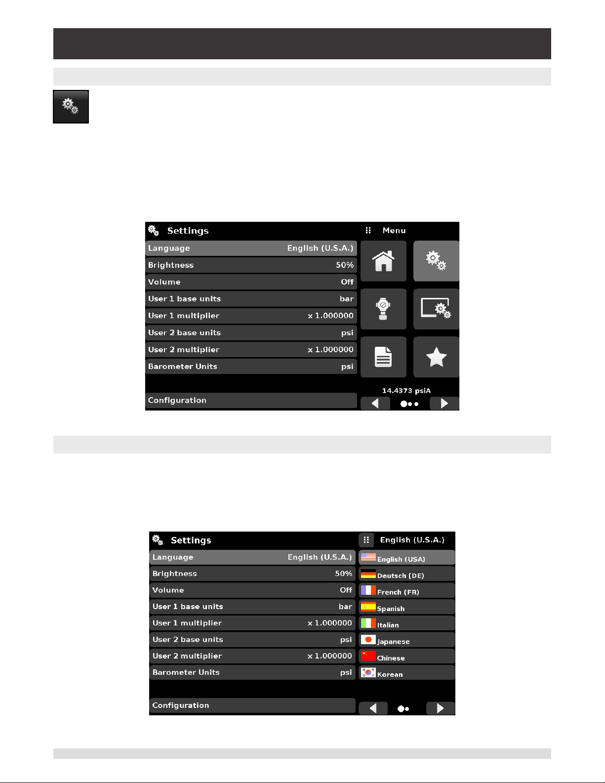
6.4.2 Settings Application
The Settings App is used to set up general settings for the display. Settings parameters include
Language, Brightness, Volume, User 1 base units, User 1 multiplier, User 2 base units, User 2
multiplier, Barometer units, and Conguration. Figure 6.4.2 shows these parameters as indicated when the Settings App has been chosen. As each parameter is pressed, an input screen will
appear on the right where selections can be made.
The Settings App provides a place to change the language, display brightness, volume, user units, and
barometer units. Conguration settings of the unit can also be saved within this application plus the default conguration can be activated.
Figure 6.4.2 – Settings application
6.4.2.1 Languages
The Language parameter provides a selection of dierent languages. Once a language is chosen all
words within all menus will appear in the chosen language and the radix character (decimal mark) will
change from a dot (.) to a comma (,) depending on the language chosen. More languages can be accessed by navigating to the next page of the language selection menu on the right side of the screen.
Figure 6.4.2.1 – Languages
38 Operating Instructions - CPC4000
Page 39
Industrial Pressure Controller
CPC4000
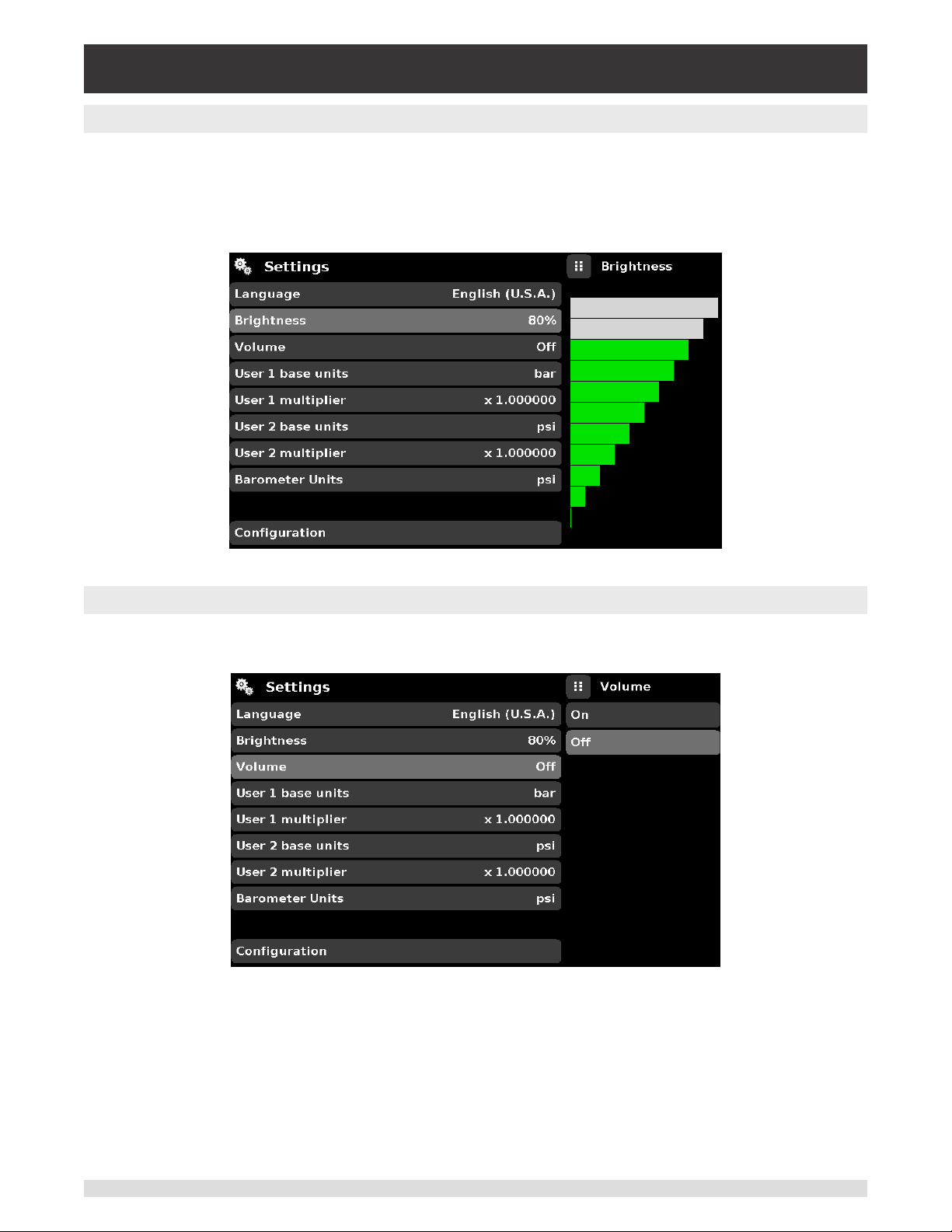
6.4.2.2 Brightness
The Brightness setting provides a sliding scale to increment the screen brightness in all screens. Slid-
ing your nger along the bar graph or touching anywhere in the bar graph will change the brightness of
the screen. After the setting is made and your nger is removed from the screen the menu will show the
brightness percent selected.
Figure 6.4.2.2 – Brightness
6.4.2.3 Volume
The Volume setting provides a way to turn on or o the touch screen audio feedback.
Figure 6.4.2.3 – Volume
Operating Instructions - CPC4000 39
Page 40
Industrial Pressure Controller
CPC4000
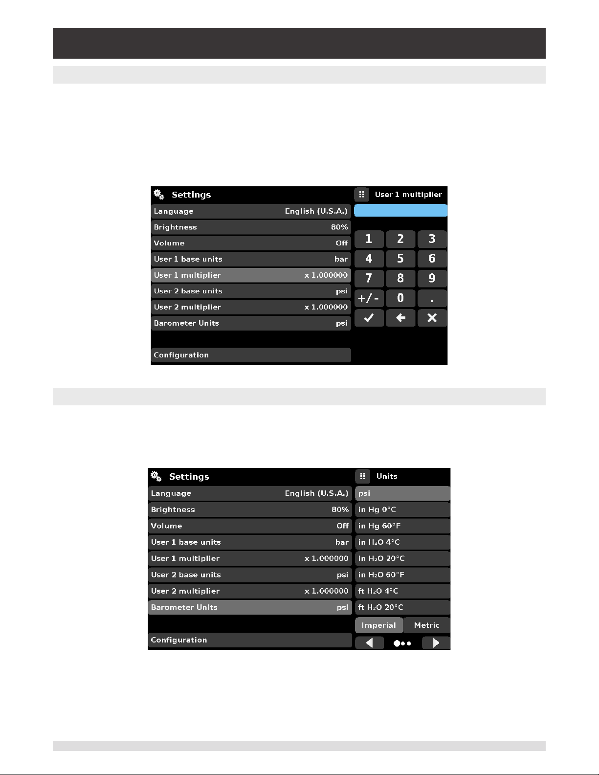
6.4.2.4 User Base Units / Base Units Multiplier
When choosing a unit of measure from the Home Application (main screen), standard units can be cho-
sen in addition to two user dened units. User units 1 and 2 are dened in the Settings App using “User 1
base units”, “User 1 multiplier” and / or “User 2 base units”, “User 2 multiplier”. For example, if the display
of one atmosphere (atm) was needed, then psi could be chosen as the “User 1 base unit” and the “User 1
multiplier”, in this case, would be 0.068045. When set this way and the user 1 unit has been chosen, the
user 1 unit will now display the pressure in atm.
Figure 6.4.2.4 – User base units / Base units multiplier
6.4.2.5 Barometer Units
When the Barometer Units Parameter has been chosen, a list of Imperial or Metric units is presented on
the right side of the screen. Any of these units can be chosen from this list for the barometric readout that
can be seen on the bottom right of the Home App.
Figure 6.4.2.5 – Barometer units
40 Operating Instructions - CPC4000
Page 41

Industrial Pressure Controller
CPC4000
6.4.2.6 Conguration
Conguration is the last parameter in the Settings App. It allows the operator to save instrument settings
and load them, as needed, in the future. Parameters that are set in the Settings App, the Frames App, the
Transducer App, and the Remote App can be saved using the Conguration “Save” button and recalled
using the Conguration “Load” button. Simply set all desired parameters then go to Settings-Conguration, press one of the numbered Conguration buttons then press the “Save” button. This will save the
current conguration in that button. To reload a saved conguration at a later time, go to Settings-Conguration and press the numbered conguration button corresponding to the saved conguration and then
press the “Load” button.
Figure 6.4.2.6 – Conguration
The instrument default conguration can be activated simply by pressing the “Default” Button.
Operating Instructions - CPC4000 41
Page 42
Industrial Pressure Controller
CPC4000
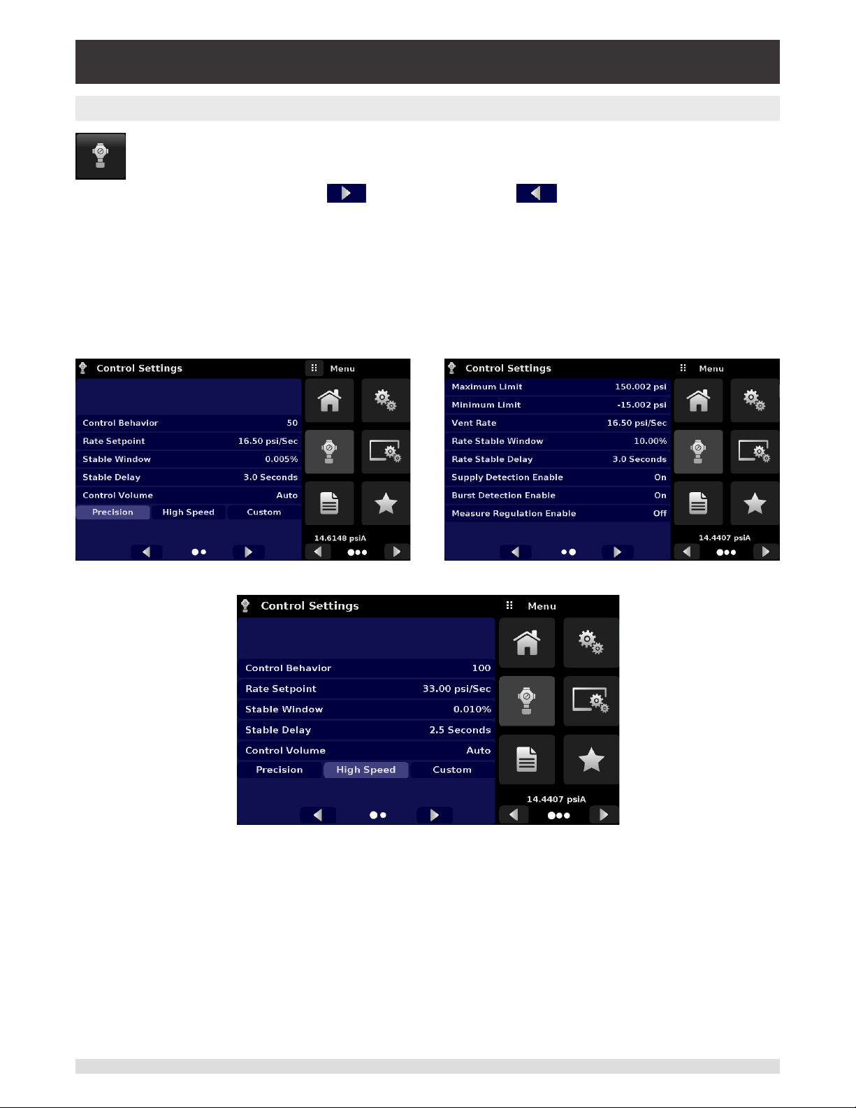
6.4.3 Control Settings Application
The Control Settings App allows the user to select and congure the control parameters for the
solenoid valve regulator in the instrument. This display remains the same for either one or two
transducer instruments. The Control Settings screen is divided into two pages and can be navigated using the Next Page [ ] and Previous Page [ ] buttons. The Control Settings
App provides two preset control modes “Precision” and “High Speed” which aect the “Control
Behavior”, “Rate Setpoint”, “Stable Window” and “Stable Delay”. The Precision control mode is
set as default and provides a stable control rate at medium overshoots. The High Speed control
mode provides faster control rate at a higher overshoot. Each of the control parameters can be
changed by the user to best suit their application in the “Custom” control mode. The “Custom”
control mode retains the values of the parameters entered by the user untill the user changes it
again. Figure 6.4.3-A and Figure 6.4.3-B show the App display for Control Settings App. Figure
6.4.3-C shows the rst page of the Control Settings App in “High-Speed” control modes.
Figure 6.4.3-A – Control Settings App Figure 6.4.3-B – Control Setting App
Figure 6.4.3-C – High Speed control mode
42 Operating Instructions - CPC4000
Page 43

Industrial Pressure Controller
CPC4000
6.4.3.1 Control Behavior
The Control Behavior button in the Control Settings App provides a choice between dierent levels of
control behavior ranging from “0” to “100” where “0” represents lowest overshoot control mode and “100”
represents High Speed control mode. The Control Behavior is preset to “50” for Precision control mode
and to “100” for High Speed control mode. The Control Behavior can be changed using the sliding scale.
Figure 6.4.3.1 shows the sliding bar to adjust control behavior in the Custom control mode.
Figure 6.4.3.1 – Control Limit Setting
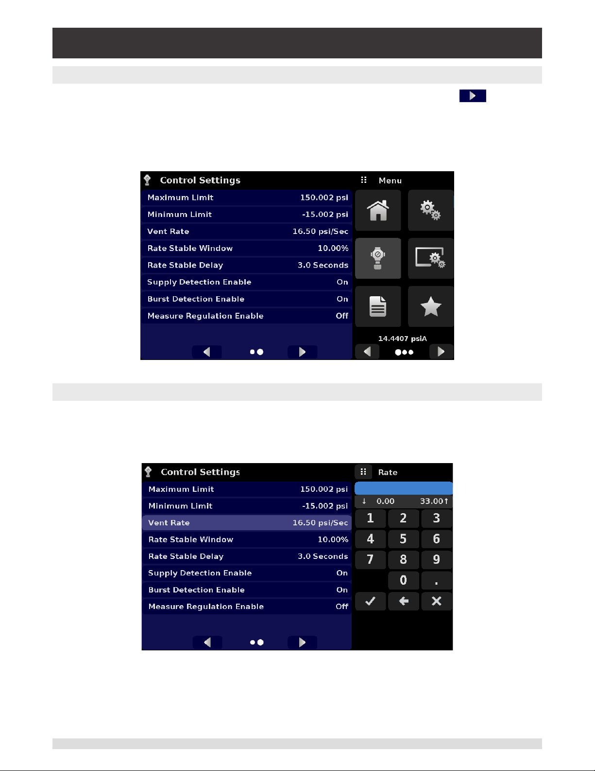
6.4.3.2 Rate Setpoint
The Rate Setpoint button allows the user to set the rate of pressure change when the CPC4000 is con-
trolling up or down to a setpoint (gure 6.4.3.2). The rate is limited to 0.1% of span of primary range of the
transducer/second to 20% of the full scale range/second.
Figure 6.4.3.2 – Rate Setpoint
Operating Instructions - CPC4000 43
Page 44

Industrial Pressure Controller
CPC4000
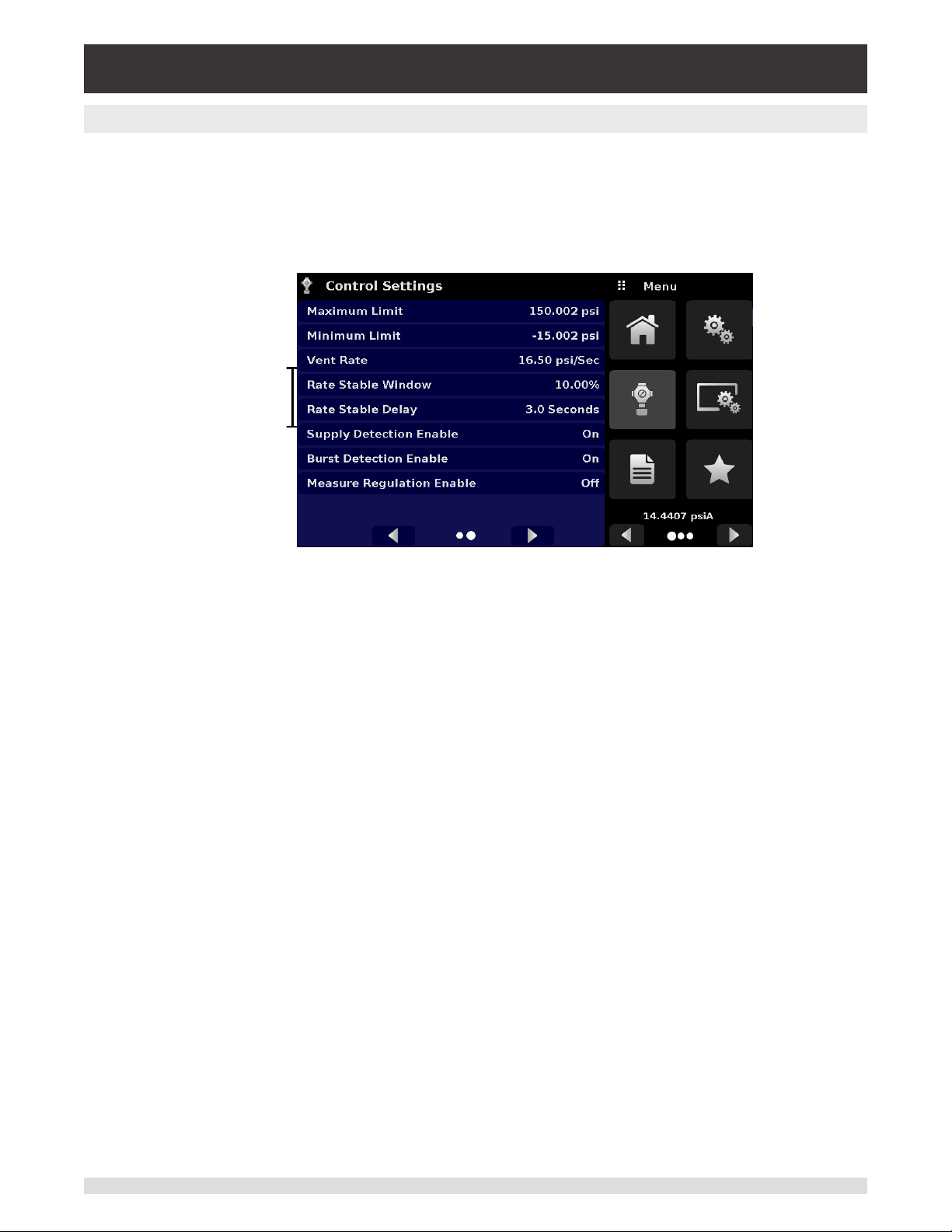
6.4.3.3 Stability Parameters
Stability parameters for the controlled pressure can be found in the Control Settings App and can be
congured using the Stable Window and Stable Delay buttons. When the controller enters a stable condition the pressure indication color on the Home App will change from white to green. The Stable Window
button allows the user to enter a value as a percentage of the highest range transducer. This value represents the pressure window within which any setpoint value would be considered stable by the user. The
Stable Delay button lets the user add a desired delay until the pressure value is considered stable while
being in the stable window.
Stability Parameters
Figure 6.4.3.3 – Stability Parameters
6.4.3.4 Control Volume
The Control Volume button in the Control Settings App allows the user to control pressure volume in
“cc”. The CPC4000 is capable of automatically identifying the control pressure volume and adjusting the
control parameters based on it. By default this button is set on “Auto”. Figure 6.4.3.4 displays the control
volume setting for the instrument.
Figure 6.4.3.4 – Control Volume
44 Operating Instructions - CPC4000
Page 45
Industrial Pressure Controller
CPC4000
6.4.3.5 Control Limits
The Maximum and Minimum Limit buttons can be accessed by clicking the Next Page [ ] button in
the Control Settings App. These buttons provide a place to limit the setpoint value that can be chosen
in the Home App. These limits can only be set within the range of the active transducer. When the instrument is in Autorange the limits can only be set within the range of the primary transducer which, by convention, will have the widest range. The minimum limit must be lower than the maximum limit. The user
cannot enter setpoints and thereby not control to pressures outside of these limits.
Figure 6.4.3.5 – Control limits
6.4.3.6 Vent Rate
The Vent Rate button in the Control Settings App lets the user to determine the rate at which pressure
will vent in vent mode. By default the rate of the vent is set similar to the control rate. The rate is limited
to a maximum of 20% of the full scale range/ second. Figure 6.4.3.6 displays the vent rate setting for the
instrument.
Figure 6.4.3.6 – Vent rate
Operating Instructions - CPC4000 45
Page 46
Industrial Pressure Controller
CPC4000
6.4.3.7 Rate Stability Parameters
Rate parameters for the control rate can be found in the Control Settings App and can be congured using the Rate Stable Window and Rate Stable Delay buttons. The Rate Stable Window button allows the
user to enter a value as a percentage of the active range of transducer. This value represents the pressure window within which the control rate value would be considered stable by the user. The Rate Stable
Delay button lets the user add a desired delay until the control rate is considered stable while being in the
rate stable window.
Rate
Parameters
Figure 6.4.3.7 – Rate Parameters
46 Operating Instructions - CPC4000
Page 47
Industrial Pressure Controller
CPC4000
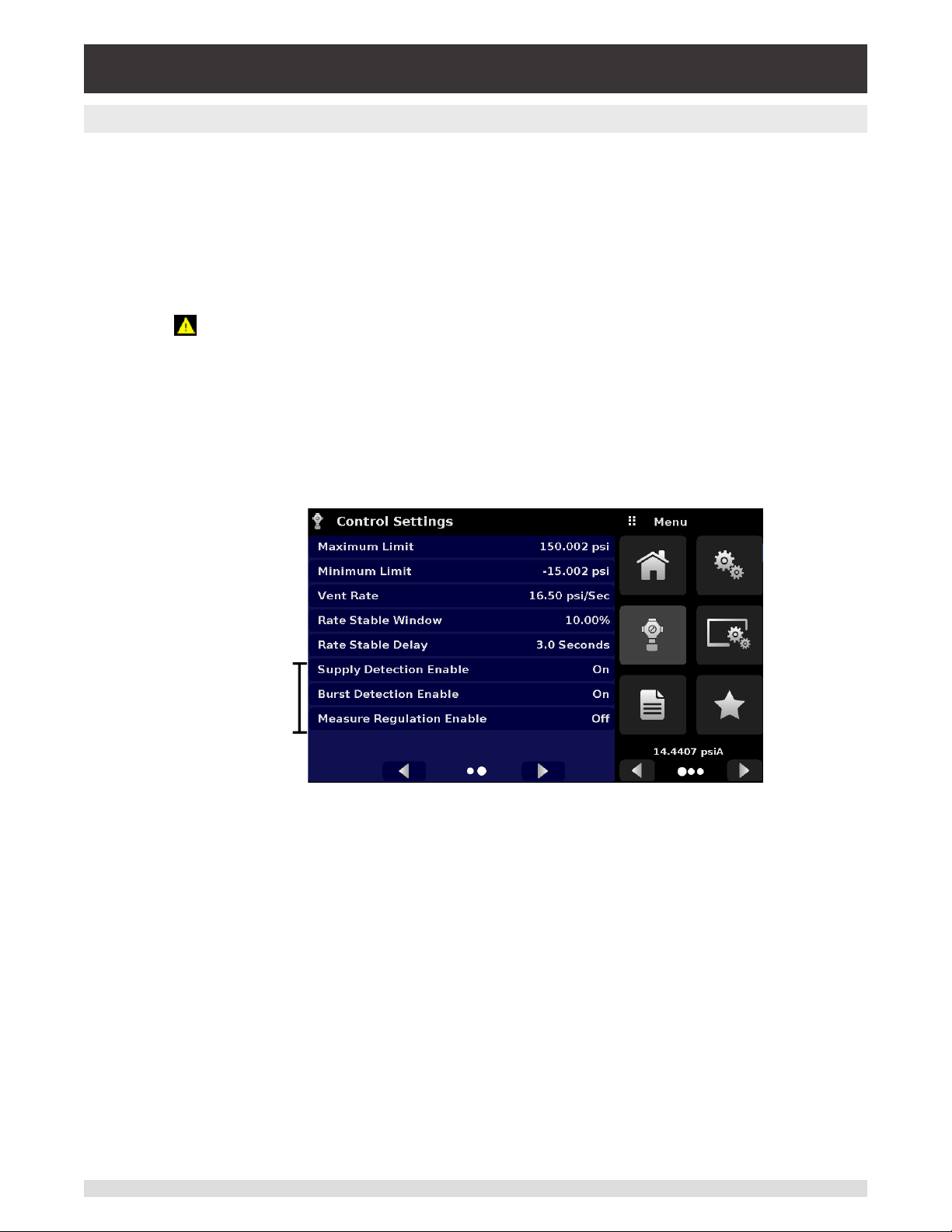
6.4.3.8 Detection Flags
The CPC4000 Industrial Pressure Controller is equipped with three detection ags that can be enabled
or disabled by the user as needed. These detection ags appear in the Control Settings App. The primary purpose of these detection ags is to protect the instrument and to ensure desired operation. Each
of these ags can be turned “On” or “O” as per user’s need. Figure 6.4.3.8 shows the detection ag set-
tings.
• Supply Detection Enable: If turned “On”, this ag allows the user to check for sucient supply pres-
sure at the Supply Port of the instrument. In case the supply pressure is less than over 10% of the
control setpoint, an error is reported which can be seen in the Troubleshoot App by clicking the error
symbol [ ]. This ag is turned “O” by default.
• Burst Detection Enable: If turned “On”, this ag allows the user to protect the instrument against sud-
den bursts in the pressure at the Measure/ Control Port. In case a burst is detected, an error is report-
ed which can be seen in the Troubleshoot App. This ag is turned “On” by default.
• Measure Regulation Enable: If turned “On”, this ag allows pressure to be controlled while the instru-
ment is in “Measure” mode to prevent pressure leaks in the system over time. This will turn on the internal pressure regulator periodically to control pressure in a certain range of the measured pressure
value. This ag is turned “O” by default.
Detection Flags
Figure 6.4.3.8 – Detection Flags
Operating Instructions - CPC4000 47
Page 48

Industrial Pressure Controller
CPC4000
6.4.4 Display Settings Application
The Display Settings Application allows the user to congure display properties like the lter for
the reading to reduce uctuations due to electrical noise, and to set the resolution of the reading. In addition, the bar graph display and calibration function can be specied here.
Figure 6.4.4 – Display Settings Application
6.4.4.1 Reading Filter
The Filter is an electronic lter to smooth out the pressure readings. Because of dierences in resolution,
greater ltering may display a more stable reading for some pressure units. Turn o the Filter by selecting
“O”, select varying degrees of ltering for the current units by selecting “Low”, “Normal” or “High”.
Figure 6.4.4.1 – Channel Selection
48 Operating Instructions - CPC4000
Page 49
Industrial Pressure Controller
CPC4000
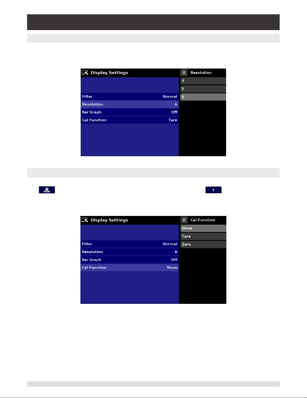
6.4.4.2 Reading Resolution
The Resolution of the displayed pressure value for each Channel can be set in the Display Settings Application using the resolution Parameter. The resolution can be set to 4, 5 or 6 digits.
Figure 6.4.4.2 – Reading Resolution
6.4.4.3 Cal Functions
The Cal Function presents a choice of None, Tare or Zero. Choosing Zero will enable the Zero Cal Button [ ] in the Home App. Choosing Tare will enable the Tare Button [ ] in the Home App. The
Tare button and the Zero Button cannot appear on the screen at the same time. See section 6.4.1.6 and
6.4.1.7 for operation of the Zero and Tare buttons in the Home App (main screen).
Figure 6.4.4.3 – Cal Function
Operating Instructions - CPC4000 49
Page 50
Industrial Pressure Controller
CPC4000
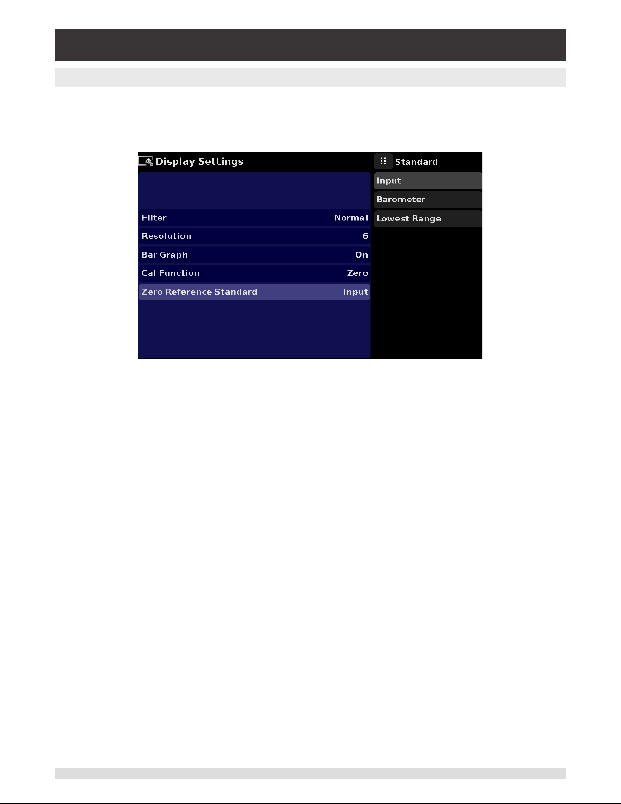
6.4.4.4 Zero Reference Standard
The Zero Reference Standard selection appears on the Display Settings App when an instrument with absolute transducers is selected. It presents a choice of Input, Barometer and Lowest Range of the transducer as
a reference for zeroing the absolute transducers. By default, keypad entry (Input) is selected as the reference which allows the user to enter a value from an external zero reference.
Figure 6. 4.4.5 - Zero Reference Standard
50 Operating Instructions - CPC4000
Page 51
Industrial Pressure Controller
CPC4000
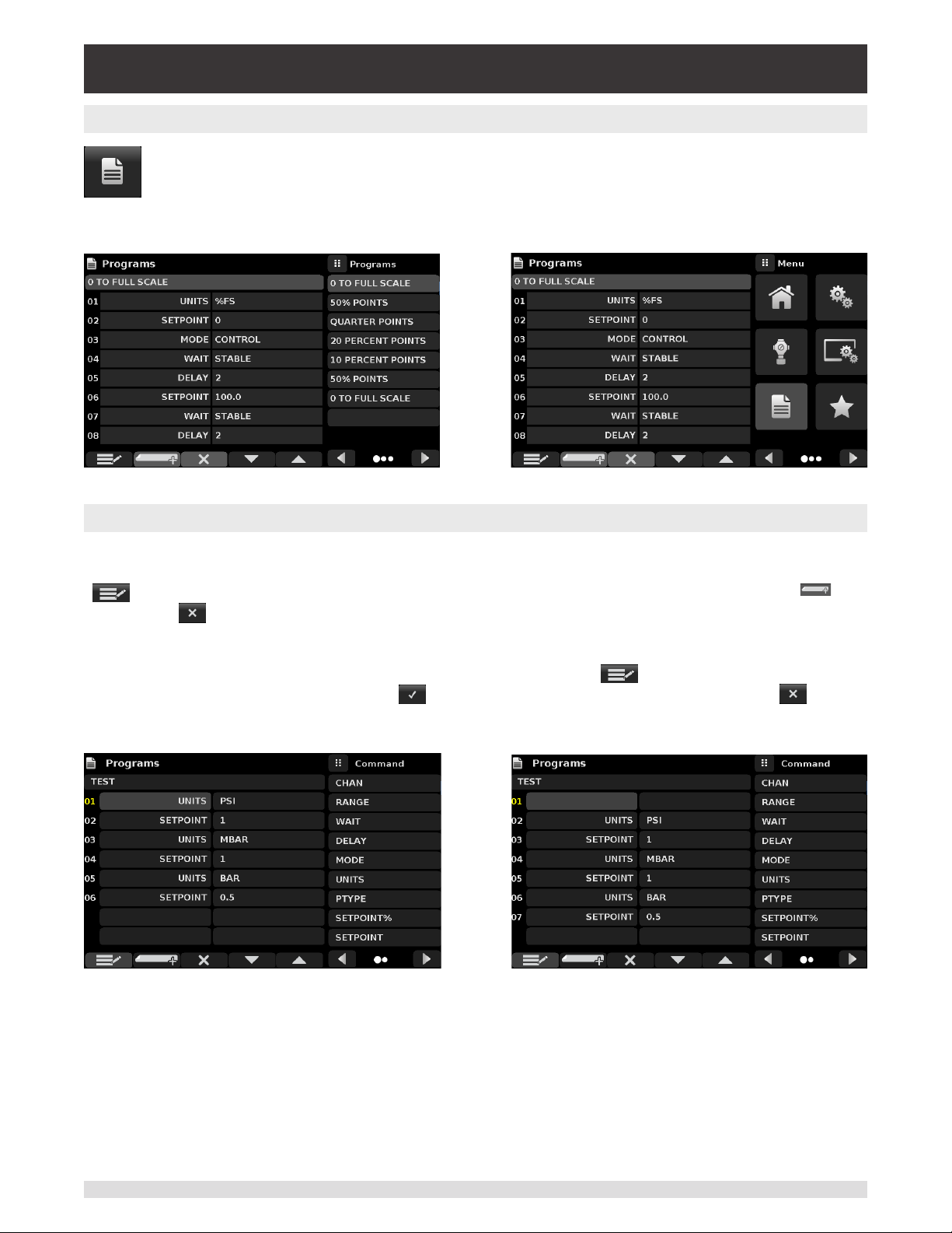
6.4.5 Programs Application
The Programs Application is used to create, view and edit programs that are used to automatically run a sequence of commands within the CPC4000. The Programs App screen displays
the contents of the rst written program in read only mode by default (gure 6.4.5-A). User can
load, edit and delete other saved and predened programs by clicking on the title of the current
program and then selecting the desired program sequence from the sidebar (gure 6.4.5-B).
Figure 6.4.5-A – Programs Application Figure 6.4.5-B – Programs Selection
6.4.5.1 Edit Programs
By default the programs are available in read only mode to prevent accidental changes to existing programs. The users can edit existing programs or create steps in new ones by clicking on Edit Program
[ ] button (gure 6.4.5.1-A). This makes the program editable and also activates the Insert [ ]
and Delete [ ] buttons which are otherwise just labels and can’t be clicked by the user. A series of
predened commands can be chosen to write the steps of a program. Selection of commands and data
in each sequential line will create a draft of resulting command sequence in the selected program (gure
6.4.5.1-B). Upon exiting the edit mode by pressing the Edit Program [ ] button, the system will ask
“Save changed programs?” Pressing the [ ] button will accept the changes, pressing the [ ] will
revert back to the old program. A list of available commands, data values and their functions are listed in
table 6.4.5.1.
Figure 6.4.5.1-A – Editable Programs App Figure 6.4.5.1-B – New Line Creation
Operating Instructions - CPC4000 51
Page 52

Industrial Pressure Controller
CPC4000
Table 6.4.5.1 – Sequence Commands
Command Function (data selection)
CHAN Sets the active channel for subsequent commands
RANGE Sets the active range for the active channel
WAIT Waits for a manual input or stable condition (Stable or Input)
DELAY Delays for time = 1 to 3600 seconds (Numerical Entry)
MODE Sets the control mode (Measure, Control or Vent)
UNITS Sets the pressure unit for operation
PTYPE Sets the pressure type (Gauge or Absolute)
SETPOINT% Sets the control setpoint in % of current range (Numerical Entry)
SETPOINT Sets the control setpoint for the instrument (Numerical Entry)
STEP% Increases or decreases the current setpoint by the percent full
scale specied
STEP Increases or decreases the current setpoint in current units (Nu-
merical Entry)
RSETPT Sets the rate setpoint in current units (Numerical Entry)
SEQZERO Set the zero for the current active transducer
SEQSTART Starts the sequence from the beginning (None)
RUNITS Sets the rate denominator time unit (min or sec)
52 Operating Instructions - CPC4000
Page 53
Industrial Pressure Controller
CPC4000
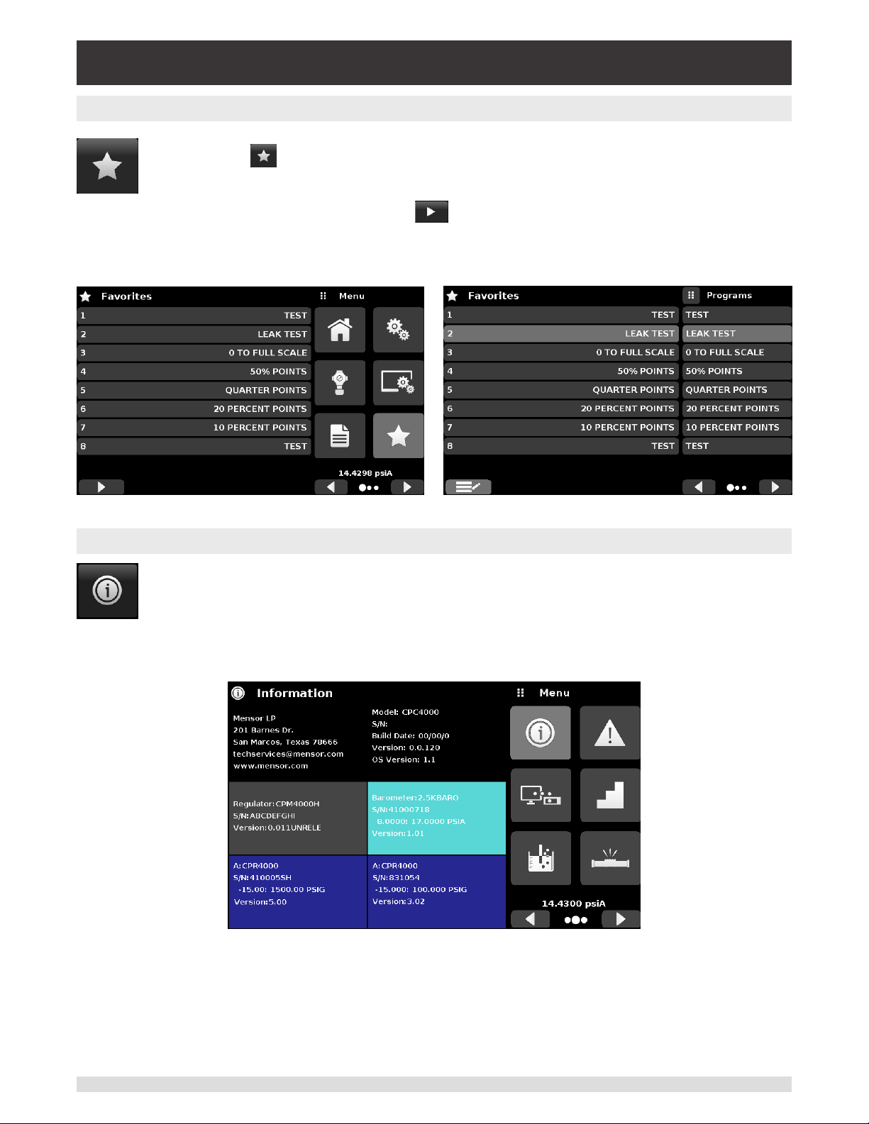
6.4.6 Favorites Application
The Favorites Application is used to select programs that will appear in the Home App when
the Favorites [ ] is pressed. The purpose of the Favorites App is to provide quick access to
frequently used programs. The current list of favorites is shown in gure 6.4.8 and the desired
program can be run by clicking on its name which takes the user to the Programs App. The list
of favorites can be edited by clicking on the Play [ ] button. The list of programs in the Favorites App
can be chosen by clicking a program from the list on the left and replaced by clicking a predened or
saved programs shown on the right side of the screen. A maximum of eight programs can be stored as
favorites.
6.4.7 Information Application
The Information Application displays information about the instrument, including:
• Mensor address, and email
• Model number, serial number and operating software version.
• Regulator model number, serial number and software version.
• Transducer model numbers, serial number, range and software version
Figure 6.4.6 – Favorites Application
Figure 6.4.7 – Information Application
Operating Instructions - CPC4000 53
Page 54
Industrial Pressure Controller
CPC4000
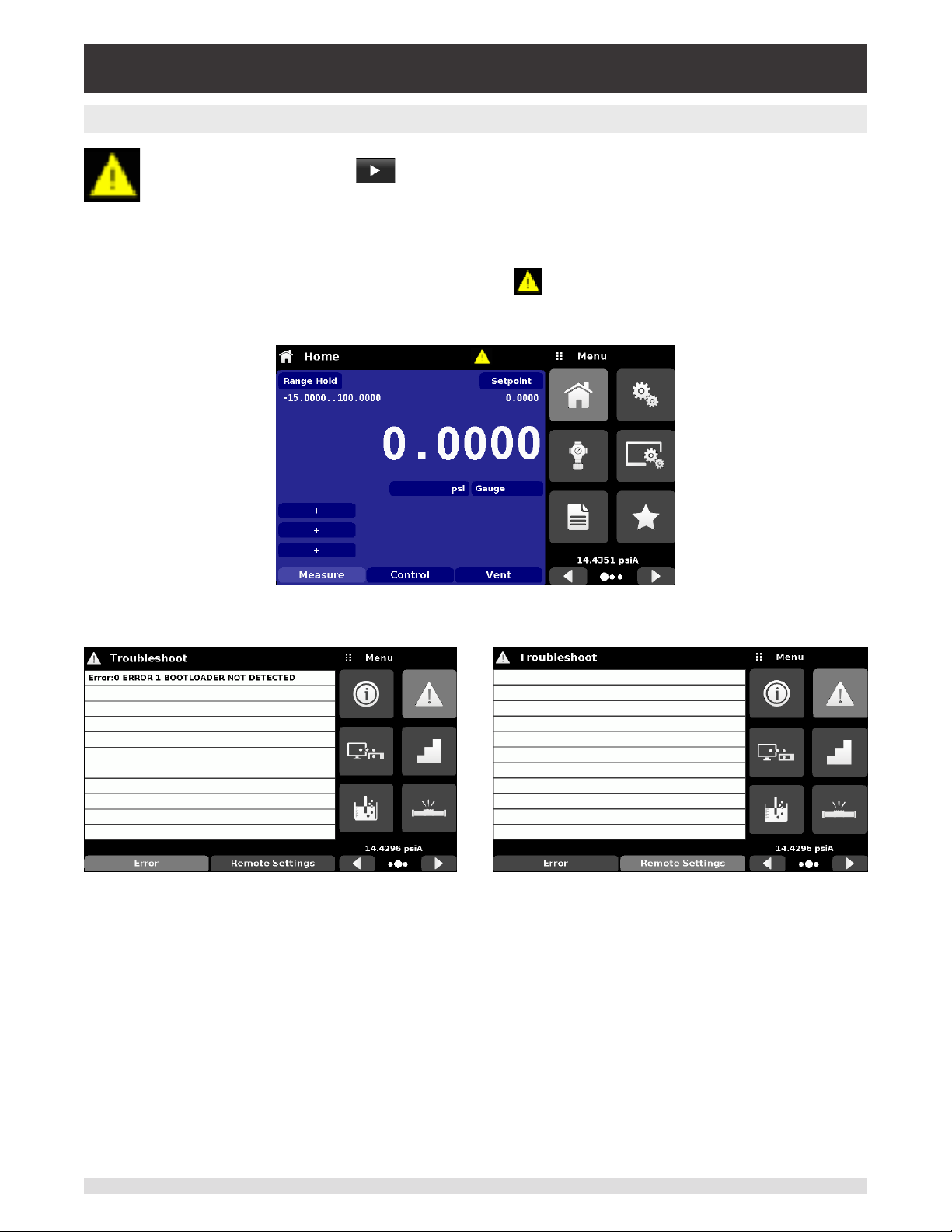
6.4.8 Troubleshooting Application
The Troubleshoot Application can be found by navigating to the second page in Apps section by
clicking on the Next Page [ ] button. The Troubleshoot App will display information about
error conditions and remote communications. Within the troubleshoot screen (Figure 6.4.8 -B),
push the Error button to display any errors that have occurred in the instrument due to a communication or network error. Push the Remote Settings button (Figure 6.4.8-C) to show commands and responses that have been sent over the remote communication connection.
If there are any errors in the error queue an error symbol [ ] will appear in all screens (Figure 6.4.8 -A)
of the instrument. Pressing this error button from any screen will open the Troubleshoot application where
the error can be viewed.
Figure 6.4.8-A – Error indication
Figure 6.4.8-B – Troubleshoot error screen Figure 6.4.8-C – Troubleshoot remote screen
54 Operating Instructions - CPC4000
Page 55

Industrial Pressure Controller
CPC4000
6.4.9 Remote Application
With the Remote Settings application user can select the remote command set for all interfaces.
The GPIB address, Ethernet network parameters and Serial parameters can also be set here.
Details about the Remote Operation (command sets, cable requirements, etc.) can be found in
Section 7, Remote Operation.
Figure 6.4.9 – Remote Application
6.4.9.1 Remote Command Set
The remote command set parameter provides a choice of the Mensor command set or the WIKA SCPI /
DPI command set (Figure 6.4.9.1 -A). Both sets of commands are listed in Section 7, Remote Operation.
Figure 6.4.9.1 - A – Remote Command Set
The DPI5xx command also provides an option to set the Checksum (Figure 6.4.9.1 - B) which when set
to ON or AUTO appends a mod base 100 checksum to end of any remote communication response.
A proper mod base 100 checksum must be sent to the instrument when the checksum is ON. Sending
the checksum is optional when set to AUTO. The ow control is set to NONE as default internally. The
termination character sets the output termination character for all remote communication command sets
(Figure 6.4.9.1 - C). The commands are listed in Section 7, Remote Operation.
Operating Instructions - CPC4000 55
Page 56

Industrial Pressure Controller
CPC4000
Figure 6.4.9.1 - B – Checksum Figure 6.4.9.1 - C - Termination character
6.4.9.2 Remote Communication Settings
The remainder of the Parameters in the Remote Application present the choice of a numeric entry, a
numeric address entry, or a radio button selection. The parameters that require a numeric entry will
present a numeric keypad with min and max limits for the variable. The parameters that require a numeric
address (for example an IP address) will also present a keypad. Address entries should conform to the
format of the parameter selected. The three screens below show examples of each type.
Numeric entry
If DHCP is enabled, the IP address, Netmask and
Gateway are greyed out and locked, these are
controlled by the DHCP server.
Radio button selection
Figure 6.4.9.2-A – Remote Communication Settings
56 Operating Instructions - CPC4000
Numeric address entry
Setting the Ethernet DHCP to yes will
have a short delay while the DHCP
i
server is contacted. If a DHCP server
is not found, an error will be indicated.
Page 57
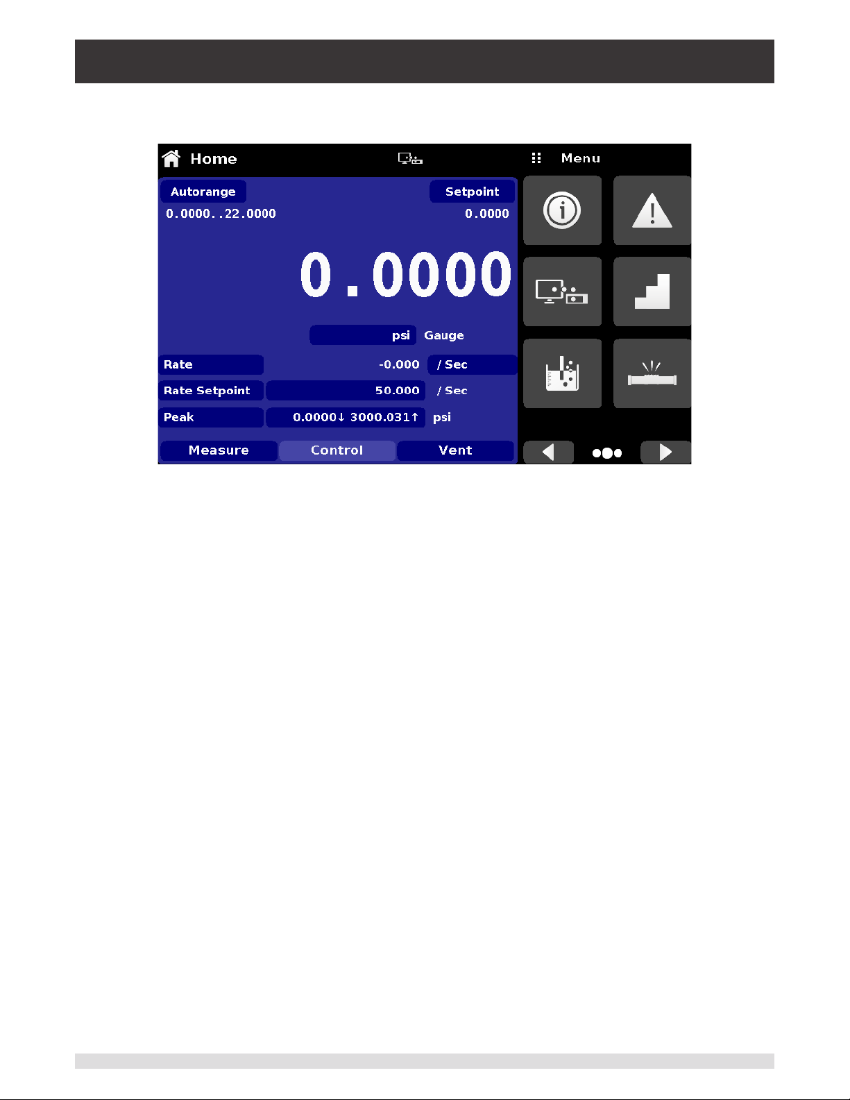
Industrial Pressure Controller
CPC4000
A successful communication link between the instrument and the various interfaces is indicated by a
Remote Settings Icon at the top of the screen (gure 6.4.9.2-B).
`Figure 6.4.9.2-B – Remote Settings Icon
Operating Instructions - CPC4000 57
Page 58

Industrial Pressure Controller
CPC4000
6.4.10 Step Settings Application
The Step Settings Application allows the user to enter control setpoint value or write program
sequences as a factor of the percentage of the device under test operating pressure range or
as xed pressure values (gure 6.4.10). The user can enter the minimum and maximum range
of the device under test (gure 6.4.10-A) and then select the desired percentage value(s) or
desired xed pressure value(s) for setpoint(s). These ranges should be within the maximum
range of the primary transducer.. The user can also enter the control point up to a maximum of
5% over the range of the device under test limits by entering the overrange percentage (gure
6.4.10-B). CPC4000 automatically calculates the pressure value of the setpoint based on this
selection. The user can be directed to this application from the setpoint entry menu in the Home
App (section 6.4.1.2).
Figure 6.4.10 – Step Settings Application
Figure 6.4.10-A – Range Selection
Figure 6.4.10-B - Overrange Selection
58 Operating Instructions - CPC4000
Page 59

Industrial Pressure Controller
CPC4000
6.4.10.1 Preset Steps
The user can have up to 12 dierent points along the range of the device under test (DUT). The Preset
Steps button allows the user to enter the number of points and then automatically divides the range in
equivalent percentages. For example if the user needs 5 distinct points along the DUT range then enter 5
in the numeric keypad and press Enter [ ] button. CPC4000 will create setpoints at 20%, 40%, 60%,
80% and 100% of the DUT range. The user also has the option of changing these percentage values as
per his/ her desire by clicking on the individual Percentage button on the Step Settings app. The user can
enter any percentage between 0 and 100. The desired value can then be chosen by checking the box
[ ] beside the Percentage button.
Figure 6.4.10.1-A – Preset Steps Entry
Figure 6.4.10.1-B – Percentage Value Entry
Operating Instructions - CPC4000 59
Page 60
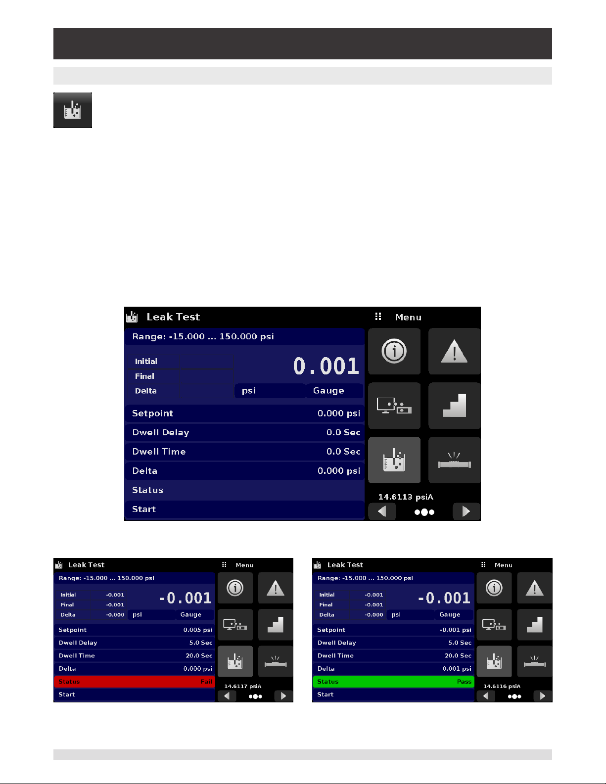
Industrial Pressure Controller
CPC4000
6.4.11 Leak Test Application
Leak test is a device under test specic feature (gure 6.4.11). The user selects the transducer
rst and then denes a leak by setting the Dwell Delay and the Dwell Time, Delta and Setpoint
parameters. The leak test is initiated by pressing the Start button.
Dwell Delay: The amount of time the controller remains at the Setpoint before the test begins.
Dwell Time: The amount of time the controller is monitoring the pressure change.
Delta: The change in pressure during the test that determines a pass or fail result.
Setpoint: The controller pressure at which the test begins.
If the change in pressure exceeds the Delta parameter before the allotted time in the Dwell Time
parameter, then the Leak Test App will return a red status indication showing initial, nal and the actual
dierence (delta) in pressure recorded, and indicate a “failed” test. Otherwise it will return a green status
indication showing the delta was not exceeded for the Dwell Time, and indicate a “passed” test. See
Figure 6.4.11-A for examples of a failed and a passed test.
Figure 6.4.11 – Leak Test
Figure 6.4.11-A – Leak test fail (left) & Leak test pass (right)t
60 Operating Instructions - CPC4000
Page 61
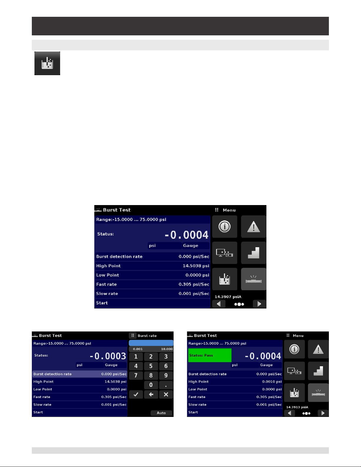
Industrial Pressure Controller
CPC4000
6.4.12 Burst Test Application
The Burst Test Application tests the burst pressure of an external device. A device such as a
rupture disk or any device that must be tested for burst pressure can be connected to the
Measure / Control port. Enter the Parameters below then press start to initiate the test.
• Burst Detection Rate: The threshold rate used by the controller to identify a burst.
• High Point: The highest pressure that the controller will control to during the test and should be set at a
value above the point where the burst pressure is expected to be.
• Low Point: The pressure point below the value where the burst pressure is expected to be. It is also
the point where the controller switches from Fast Rate to Slow Rate.
• Fast Rate: the rate at which the controller will control pressure to the Low Point.
• Slow Rate: The rate at which the controller will control between the Low Point and the High point.
If the Device under test must experience a burst condition between the Low Point and the High Point the
instrument will indicate the burst point at the end of the test. If the device under test does not experience
a burst condition the burst test screen will indicate a complete status. The burst test is initiated by press-
ing the Start button. Figure 6.4.12-A, 6.4.12-B and 6.4.12-C show the dierent status messages during a
burst test.
Figure 6.4.12 - A – Burst test screen
Figure 6.4.12-B – Burst detected Figure 6.4.12-C – No burst detected
Operating Instructions - CPC4000 61
Page 62

Industrial Pressure Controller
CPC4000
6.4.13 Service Application
The service application can be found by navigating to the third page by clicking the Next Page
[ ] button at the bottom right corner of the App section of the screen. It is a password
protected area allowing access to calibration menu for all the sensors and technical assistance
menu. In addition, this is where the password for entering this area can be changed.
Figure 6.4.13-A – Service Application (locked)
Press the Enter button to show the numeric keypad to enter a password. This will unlock other applications.
• Default password for calibration menu is 123456
• Default password for technical assistance menu is 111111
Enter password and press the check mark [ ] to unlock the Service Application.
Figure 6.4.13-B – Service Application (Enter Password)
Note: After entering the default password for the rst time, the password can be changed.
i
62 Operating Instructions - CPC4000
Page 63

Industrial Pressure Controller
CPC4000
6.4.14 Unlocked Service Application
After the Password has been entered, the unlocked Service Application will appear (Figure 6.4.14-A & B).
To re-lock this screen, press the lock button.
Figure 6.4.14-A – Unlocked Service Application - Calibration Menu
Figure 6.4.14-B - Unlocked Service Application - Technical Assistance Menu
From the Unlocked Service Application, the Password can be changed by pressing the Enter button next
to the Change Password label. This will open a keypad where a new password can be entered and accepted by pressing the Check Mark [ ].
Note: Please make note of a password change and save the new password in a secure
i
The Unlocked Service Application is the access point to all calibration screens described in Section 10 of
this manual or all the technical screens described in Section 11 of this manual.
i
Operating Instructions - CPC4000 63
location.
Note: Recommended calibration setup and explanation of calibration screen applica-
tions is covered in Section 10 of this manual.
Page 64

Industrial Pressure Controller
CPC4000
7 Remote Operation
Use the screens in Section 6.4.9 Remote Application to set the operating parameters for the instrument
command set, Ethernet, Serial (RS-232) and IEEE-488 (GPIB) information.
7.1 Command Set
Command Set button – Users’ can select which model remote protocol they would like to emulate for
simulation and testing purposes. Selections may include the standard command sets or the optional
command sets selected in the Technical Assistance menu (Section 11) :
Standard:
• Mensor (default)
• SCPI WIKA (The SCPI WIKA mode emulates the WIKA command set in SCPI format.)
• DPI 5XX
Optional:
• SCPI GE (The SCPI GE mode emulates the GE PACE command set in SCPI format.)
7.2 IEEE-488
IEEE-488 address button – Allows the user to set the GPIB address by inputting a numeric value utilizing
the touch screen.
7.2.1 IEEE-488.2 Commands
Command or Query Response / Function
*IDN? Returns identication string
*TST? Returns OK
*OPC Operation completed
*WAI Returns operation completed state
*CLS Clear status and error queue
*ESE Enable status event
*ESE? Returns enable status event value
*ESR Event status register
*ESR? Returns event status register value
*SRE Service request enable
*SRE? Returns service request enable value
*STB? Returns status byte
64 Operating Instructions - CPC4000
Page 65

Industrial Pressure Controller
CPC4000
7.3 Ethernet
The Ethernet function allows the user to set the following by inputting a numeric value in each separate
eld:
• IP
• Netmask
• Gateway
• Port
• DHCP settings
Set the Ethernet communication parameters as described in Section 6.4.9.
!
CAUTION: Please contact your network administrator for proper settings.
Caution
CAUTION: Please consult your computer resources department prior to connect-
ingthisinstrumenttoyournetworktoverifytherearenoconictswithexistingIP
!
Caution
The Ethernet communication port allows the CPC4000 to communicate with computers using
10/100Based-T specications.
Before using Ethernet communication, four parameters must be set up: IP, Netmask, Gateway, and Port.
addresses.
Operating Instructions - CPC4000 65
Page 66

Industrial Pressure Controller
CPC4000
7.4 Serial
Set the Serial communication parameters as shown in Section 6.4.9 Remote Application. The serial communication port allows the CPC4000 to communicate in RS-232 format with computers, terminals, PDAs,
or similar hosts.
These parameters should be set to match your host computer. Default settings are: 9600 baud, 8 data
bits, 1 stop bit, no parity, and no echo.
If echo is ON, the CPC4000 will immediately echo back characters sent over the serial port. The Serial
function allows the user to set the RS-232 serial port settings by selecting from the choices provided:
• Baud
9600
19200
38400
57600
115200
• Data Bits
7
8
• Stop Bits
1
2
• Parity
Even
Odd
None
• Echo settings
On
O
7.4.1 Serial Cable Requirements
RS-232 communications are transmitted over a three conductor, shielded cable terminated in a standard
DB9 connector on the instrument end, and a dierent gender connector on the host end. The proper pin-
outs are shown in the following illustration.
66 Operating Instructions - CPC4000
Page 67

Industrial Pressure Controller
CPC4000
7.5 Mensor Command Set
This Mensor command set is the default on the CPC4000. For queries (ending with a ?), the Data column
represents the response of the CPC4000. All response strings begin with a space character or an “E” representing that there is an error in the error queue. All response strings are terminated with a <CR> and a
<LF>. The error queue holds the last 10 errors identied.
For all commands (no ?), the data column represents the required parameters to be sent to the CPC4000
following the string in the command column. For any command that requires multiple parameters to be
sent, the parameters must be separated by commas.
7.5.1 Command and Query Format
Commands must be sent in ASCII format and terminated with either a carriage return (<cr>), linefeed
(<lf>), or both. Commands are not case sensitive. Each query returns a response. If an error is detected
the response will include an error ag.
CommandorQueryeld: Unless otherwise specied, commands are typically converted to queries
by appending a question mark to the command. Table 7.5.4 lists all of the CPC4000 command or query
keywords.
Dataeld:The data eld is either in ASCII {string} or numeric {value} form. In the case of multiple data
elds, commas are required to separate the elds. Queries do not have a data eld. String (text) or value
(numeric) data are acceptable in any of the following formats:
Examples of {string} data: ON, OFF, mBar, inHg
Examples of {value} data: 1, 1.0, -5.678, 25.68324e-5
7.5.2 CommandSetDenitions
In this manual, a data entry made up of alpha characters is dened as a string, as opposed to data
containing only numbers, such as “Enter 1 for ON or 0 for OFF” where 1 and 0 are dened as values.
Command: Any command or query listed in Table 7.5.4. For commands that take boolean data the following strings are acceptable:
0 1
False True
No Yes
O On
Separator: Space (SP).
Data: ASCII representations of numbers, {value}, or alpha characters, {string}, data as dened above.
When sending code a literal variable replaces the brackets and the enclosed character(s) shown in the
following examples.
Termination: Linefeed (LF) or carriage return (CR) is used to signal the end of a command statement.
For IEEE-488.2 operation “EOI” is an acceptable alternative.
Always send commands in one of the following formats:
1. [Command] [Termination];
2. [Command] [Separator] [Data] [Termination];
3. Queries are special instructions in the form: [Command?] [Termination] where the question mark, “?”,
immediately precedes the terminator.
When a valid query is received, the CPC4000 will return {data} terminated by CR and LF. Floating point
data is returned in the current engineering units in exponential format.
Operating Instructions - CPC4000 67
Page 68

Industrial Pressure Controller
CPC4000
7.5.3 Output Formats
Pressure readings are returned in exponential notation in a format according to the OUTFORM command
as follows.
Output formats
1. <sp> pressure value <cr><lf>
2. <sp> pressure, units, mode <cr><lf>
3. <sp> pressure, pressure rate <cr><lf>
4. <sp> pressure, minimum peak, maximum peak <cr><lf>
5. <sp> pressure, active sensor (P or S) active turndown (1)<cr><lf>
6. <sp> pressure, control point, “stable” or “slewing”<cr><lf>
7. <sp> pressure, “no barometer” or baro reading<cr><lf>
7.5.4 Mensor Command Set and Queries
Table 7.5.4 lists all of the current CPC4000 commands and queries.
Optional emulation modes are available in which a CPC4000 can emulate remote functions of dierent
brands of pressure gauges. Please contact Mensor for more details.
Table 7.5.4 - CPC4000 Mensor Command Set
Command Data Response/Function
? See Section 7.5.3 Returns data per the current output
format
Acquire? 15 char string.
Ex:
Acquire? Test_stand_1
Returns:
<sp>(YES or NO), CCC…
CCC<cr><lf>
This command is used when multiple
computers would like to control the
instrument.
Yes if acquisition is successful
No if instrument is being controlled
with another computer
CCC… = name of controlling computer
(see Release? and Unlock)
Address 1-31 Sets the GPIB Address
Address? <sp>nn<cr><lf> Returns the GPIB Address
Asset_tag 16 char string General purpose string for customer
use
Asset_tag? <sp>ssssssssssssssss<cr><lf> Return customer asset tag string
Autorange ON or OFF Sets whether the autorange function
is enabled or disabled
Autorange? <sp>(ON or OFF)<cr><lf> Returns whether the autorange func-
tion is enabled or disabled.
68 Operating Instructions - CPC4000
Page 69

Industrial Pressure Controller
CPC4000
Autozero none Re-zero all the ranges. These adjust-
ments are not password protected
and are saved permanently through
power cycles while the instrument
is in native mode (temporary while
in emulation mode). This command
takes approximately 60 seconds but
may take longer depending on the
time to become stable.
Autozero? S,T,X,X Returns autozero data where S
represents state (0 = complete, 1 =
local autozero, 2 = remote autozero),
T represents the estimated time to
complete in seconds, and x is a (0)
character since this data location is
not used at this time.
Autozeroabort none Aborts autozero. Any transducers that
have been zeroed will not revert to
previous zero osets.
Auxdisp <n> NONE,PEAK,RATE,RATE
SETPOINT,UNCERTAINTY,UNITS
Auxdisp? <n> <sp>NONE,PEAK,RATE,RATE SETP
OINT,UNCERTAINTY,UNITS<cr><lf>
Baro? <sp>+n.nnnnnE+nn<cr><lf> Returns reading from barometric
Barounits units code or text in table below Sets the barometer pressure units
Barounits? <sp>CCCC<cr><lf> Returns the barometer units in a text
Burst_Detect YES,NO Sets burst detection enable, see Sec-
Burst_Detect? <sp>(YES or NO)<cr><lf> Returns whether burst detection is
Burst_Start Changes the screen to the Burst Test
Burst_Stop Stops the test and vents the system.
Burst_State? <sp>(IDLE or RUNNING or
COMPLETE)<cr><lf>
Burst_Low value inside upper and lower limits This is the lower pressure of the an-
Burst_Low? <sp>n.nnnnnE+nn<cr><lf> Returns the lower pressure limit for
Burst_High value inside upper and lower limits This is the higher pressure limit of the
Sets the auxiliary display setting for
index <n> (0 to 2). If <n> is left out,
defaults to index 0.
Returns the auxiliary display setting
for index <n>. If <n> is left out, de-
faults to index 0.
transducer or “NO BAROMETER” if
one isn’t installed
string
tion 6.4.3.8 Detection Flags
enabled or not
if on another screen, begins the burst
test with current parameters.
Returns state of the burst test
ticipated “burst range”
burst test
anticipated “burst range”
Operating Instructions - CPC4000 69
Page 70

Industrial Pressure Controller
CPC4000
Burst_High? <sp>n.nnnnnE+nn<cr><lf> Returns the higher pressure limit for
burst test
Burst_Slow value inside upper and lower limits This is the rate used during the transi-
tion from low setpt to high setpt in the
anticipated “burst range”
Burst_Slow? <sp>n.nnnnnE+nn<cr><lf> Returns the slow rate for burst test
Burst_Fast value inside upper and lower limits This is the rate used during the transi-
tion from atmosphere to the low setpt
Burst_Fast? <sp>n.nnnnnE+nn<cr><lf> Returns the fast rate for burst test
Burst_Result? <sp>n.nnnnnE+nn<cr><lf> Pressure at which burst was detected.
Will return 0 if no burst found.
Calculate_as_found_
line arity
Caldisable YES,NO Sets whether or not calibration of the
Caldisable? <sp>(YES or NO)<cr><lf> Returns whether or not calibration of
Calibration_mode? <sp>(YES or NO)<cr><lf> Returns the current calibration mode
Calibration_mode YES, NO Enable/ disable the calibration mode,
Cerr None Clears the error queue
Cmdset Mensor, DPI510, SCPI Activates remote command set for
Cmdset? <sp><CCCCCC><cr><lf> Returns active command set identier
Control Instrument placed in Control Mode
Control? <sp>(YES or NO)<cr><lf> Returns YES if instrument is in control.
Control_behavior <n> 0 to 100 100 = highspeed, 0 = low overshoot.
Control_behavior? <sp>NNN<cr><lf> Returns the control behavior number
Control_default PRECISION, HIGHSPEED, CUSTOM
or NONE
Control_default? <sp>(PRECISION, HIGHSPEED,
CUSTOM or NONE)<cr><lf>
Crate Slow, Medium, Fast, Variable Sets the control rate, Variable mode
Calculate linearity slopes and inter-
cepts from true/actual pressures
active transducer is disabled.
the active transducer is disabled.
setting
which when on, disables the sensor
overpressure error and forces range
hold to lock the secondary shuto
valve. Normally the secondary range
is always allowed to go to its maxi-
mum pressure to avoid a large pres-
sure disturbance when switching to it.
instrument emulation modes.
NO if otherwise
May be set between 0 and 100.
Sets the current control settings
Returns the current control settings
is a predetermined user dened rate
setpt.
70 Operating Instructions - CPC4000
Page 71

Industrial Pressure Controller
CPC4000
Crate? <sp>CCCCCC<cr><lf> Returns the control rate – CCCC is
variable in length and corresponds to
the parameters for the CRATE com-
mand
Ctype? Returns the type of regulator
Decpt? <sp>n<cr><lf> Returns the number of decimal points
(see Resolution)
Default None Sets the default values
DHCP ON or OFF Reserved for DHCP setup
DHCP? <sp>(YES or NO)<cr><lf> Reserved for DHCP setup
DOC mm/dd/yyyy Sets the date of cal for the active
transducer.
DOC? <sp>mm/dd/yyyy<cr><lf> Returns the date of cal for the active
transducer.
DOM? <sp>mm/dd/yyyy<cr><lf> Returns the date of manufacture
Error? <sp> text description <cr><lf> Returns the next error in the error
queue
Errorno? <sp>Enn-text<cr><lf> Returns pcs400 error code and text
Filter OFF, LOW, NORMAL, HIGH Sets the reading lter 0, 80%, 92%,
95%
Filter? <sp> (lter)<cr><lf> Returns the reading lter.
Gasdensity Value in lb/cuft, or “NITROGEN” or
“DRYAIR”
Gasdensity? <sp>+n.nnnnnE+nn<cr> Gets the head pressure gas density in
Gastemp Value in degrees F Sets the head pressure gas tempera-
Gastemp? <sp>+n.nnnnnE+nn<cr>
<lf>
Gateway nnn.nnn.nnn.nnn Sets the Ethernet gateway address
Gateway? <sp>nnn.nnn.nnn.nnn<cr><lf> Gets the Ethernet gateway address
Height Value in inches Sets the head pressure height in
Height? <sp>+n.nnnnnE+nn<cr>
<lf>
Highspeed ON or OFF Sets the highspeed control mode,
Highspeed? <sp>(YES or NO)<cr><lf> Returns the status of the highspeed
Id? <sp>MENSOR,CPC4000,
ssssss,v.v.vv<cr><lf>
Sets the head pressure gas density in
lb/cuft
lb/cuft
ture
Gets the head pressure gas tempera-
ture
inches
Gets the head pressure height in
inches
which sets the control behavior, stable
window, stable delay, and rate setpoint
mode
Ssssss is the serial number,v.v.vv is
the CPC 4000 software version.
Operating Instructions - CPC4000 71
Page 72

Industrial Pressure Controller
CPC4000
Instrument_control_
time_on?
<sp>NNNNN<cr><lf> Returns the amount of time the instru-
ment has been in control mode since
the last reset of the counter, in minutes
Instrument_total_control_time_on?
<sp>NNNNN<cr><lf> Returns the lifetime amount of time
the instrument has been in control
mode, in minutes
Instrument_time_on? <sp>NNNNN<cr><lf> Returns the amount of time the instru-
ment has been on since the last reset
of the counter, in minutes
Instrument_total_
time_on?
<sp>NNNNN<cr><lf> Returns the lifetime amount of time
the instrument has been on, in min-
utes
IP nnn.nnn.nnn.nnn Sets the IP address of the instrument
IP? <sp>nnn.nnn.nnn.nnn<cr><lf> Returns the IP address of the instru-
ment
Keylock YES or NO Locks or unlocks the entire touch
screen
Keylock? <sp>(YES or NO)<cr><lf> Returns Yes or No
Leak_External ON or OFF Sets the leak test external valve set-
ting in Single output A or B mode only
Leak_External? <sp>(YES or NO)<cr><lf> Returns the leak test external valve
setting
Leak_Start Changes the screen to the Leak Test
if on another screen, begins the leak
test with current parameters.
Leak_Stop Stops the test and vents the system.
Leak_State? <sp>(IDLE or RUNNING or
Returns state of the leak test
COMPLETE)<cr><lf>
Leak_Setpt value inside upper and lower limits Starting point for the leak test to begin
at
Leak_Setpt? <sp>n.nnnnnE+nn<cr><lf> Returns starting setpt
Leak_Dwell 0 to 3600 The duration of the test during which
a leak is measured
Leak_Dwell? <sp>n.nnnnnE+nn<cr><lf> Returns the dwell time in seconds
Leak_Pre_Dwell 0 to 3600 Pre-dwell parameter is the time in
between going to measure mode, and
the dwell time. Useful if there are
pressure transients after switching to
measure.
Leak_Pre_Dwell? <sp>n.nnnnnE+nn<cr><lf> Returns the pre-dwell time.
Leak_Delta_Limit Value within the range of the primary
transducer
Threshold for a passing/failing leak
test.
Leak_Delta_Limit? <sp>n.nnnnnE+nn<cr><lf> Returns the maximum pressure
change allowed before failure
72 Operating Instructions - CPC4000
Page 73

Industrial Pressure Controller
CPC4000
Leak_Delta? <sp>n.nnnnnE+nn<cr><lf> Returns the change in pressure since
start of test.
Leak_Initial? <sp>+n.nnnnnE+nn<cr> Returns the leak test initial pressure
Leak_Final? <sp>+n.nnnnnE+nn<cr> Returns the leak test nal pressure
Leak_Pass? <sp>(YES or NO)<cr><lf>
List? <sp>Pri,1;Sec,1;Bar,1<cr><lf> Returns list of available transducers
and turndowns. Turndowns are un-
available for CPC4000 but returns 1
for backwards compatibility.
Listcal? <sp>PRI,{sn},1,{mmddyy};SEC,{sn},
1,{mmddyy},{sn},1,{mmddyy},BAR,{
sn},{ mmddyy}<cr><lf>
Listrange? PRI,1,min,max;SEC,1,min,max;Bar,m
in,max
Listsensorinfo? <sp>PRI,SN,PTYPE,ACCURACY,1,m
in,max,2,min,max;SEC,SN,PTYPE,A
CCURACY,1,min,max,2,min,max;<cr
><lf>
Listcong? CHA, Regtype;PRI,1,min,max;SE
C,1,min,max; CHB, Regtype;PRI,1
,min,max;SEC,1,min,max; CHbaro,
Baro;Bar,min,max
Localgravity Value in ft/s^2 Sets the local gravity in feet/sec^2
Localgravity? <sp>+n.nnnnnE+nn<cr>
<lf>
LowerLimit Value inside primary xducer range in
current units.
LowerLimit? <sp>n.nnnnnE+nn<cr>
<lf>
Macaddress? <sp>cc-cc-cc-cc-cc-cc<cr><lf> Returns Ethernet MAC address
Measure None Instrument placed in Measure Mode
Measure? <sp>(YES or NO)<cr><lf> Returns YES if instrument is in mea-
Meas_Reg ON or OFF Sets the regulation of the pressure
Meas_Reg? <sp>(YES or NO)<cr><lf> Returns whether measure regulation
Mode MEASURE, CONTROL, VENT Sets the operation mode
Mode? <sp>XXXXXX<cr><lf> Returns the operation mode
Netmask nnn.nnn.nnn.nnn Sets the Ethernet network mask
Netmask? <sp>nnn.nnn.nnn.nnn<cr><lf> Gets the Ethernet network mask
OSversion? <sp>n.n<cr><lf> Returns the operating system version
Outform 1 to 7 – see table in Section 7.8 Sets the output format
Returns list of available transducers
including serial number and date of
calibration
Returns the ranges of the installed
transducers.
Returns the serial number, pressure
type, accuracy, and ranges of the installed sensors for the active channel
Returns the regulator types (Regtype:
Pump, LPSVR, MPSVR, HPSVR,
EPSVR) along with all the ranges of
the installed transducers.
Returns the local gravity in feet/sec^2
Sets the lower control limit for the
instrument
Returns the lower control limit for the
instrument in current units.
sure. NO if otherwise
across the Measure/Control solenoid,
see Section 6.4.3.8 Detection Flags
is enabled
Operating Instructions - CPC4000 73
Page 74

Industrial Pressure Controller
CPC4000
Outform? <sp>X<cr><lf> Returns the output format – see table
in Section 7.8
Peakmax? <sp>n.nnnnnE+nn<cr>
<lf>
Peakmin? <sp>n.nnnnnE+nn<cr>
<lf>
Peakreset None Resets the peak values.
Port nnnnnn Sets the Ethernet port of the instru-
Port? <sp>nnnnn<cr><lf> Returns the Ethernet port of the in-
Precision ON or OFF Sets the precision control mode,
Precision? <sp>(YES or NO)<cr><lf> Returns the status of the precision
Ptype Absolute or Gauge Sets the instrument pressure type –
Ptype? <sp>CCCCC<cr><lf> Returns “Absolute” or “Gauge” for the
Purge Value inside upper and lower limits,
never in the vacuum region
Purge? <sp>S,T<cr><lf> Returns purge data where S repre-
Purgeabort? Aborts purge sequence if currently
RangeMax? <sp>n.nnnnnE+nn<cr>
<lf>
RangeMin? <sp>n.nnnnnE+nn<cr>
<lf>
Rate? <sp>n.nnnnnE+nn<cr>
<lf>
Rdecpt? <sp>n<cr><lf> Returns the number of rate decimal
Returns the maximum pressure since
peakreset was sent.
Returns the minimum pressure since
peakreset was sent.
ment
strument
which sets the control behavior, stable
window, stable delay, and rate setpoint
mode
emulation only works if the optional
barometric transducer is installed. If
no barometer is present, standard
atmosphere is used for the barometric
reading when in emulation mode.
pressure type in native mode and
“Absolute Emulated” or “Gauge Emulated” for the emulated pressure types
Start purge sequence with DUT pressure as the setpoint. Only applicable
with option PURGE enabled
sents state (0 = complete, 1 = local
purge, 2 = remote purge), T represents the estimated time to complete
in seconds
running. Only applicable with option
PURGE enabled
Returns the maximum range of the
active transducer in the current units.
Returns the minimum range of the active transducer in the current units.
Returns the rate reading of the instrument in current units/current time unit
(see Runits)
points.(see Resolution)
74 Operating Instructions - CPC4000
Page 75

Industrial Pressure Controller
CPC4000
Reference {EXTVAC or ATM} Sets the reference type for vacuum
pump connected to the reference, or
vented to atmosphere. This option is
available only on native gauge units.
Reference? <sp>{EXTVAC or ATM}<cr><lf> Returns the current reference type.
(see Reference)
Release? 15 char string.
Ex:
Release? Test_stand_1
Returns:
<sp>(YES or NO), CCC…
CCC<cr><lf>
Reset_instrument_
time_on
Reset_instrument_
control_time_on
Resolution <n> Sets the number of signicant digits.
Resolution? <sp>n<cr><lf> Returns the number of signicant
Rlter Value in % Sets the % of the rate lter
Rlter? <sp>n.nnnnnE+nn<cr>
<lf>
Rsetpt Value in current units Sets the rate setpoint
Rsetpt? <sp>n.nnnnnE+nn<cr>
<lf>
Runits Sec, min, hr Sets the rate time unit
Runits? <sp>XXXX<cr><lf> Returns the rate time unit
Save_cal Save calibration values
Save_linearity Save linearity values
Sbaud 9600, 19200, 38400, 57600, 115200 Sets the serial baud rate
Sbaud? <sp>XXXX<cr><lf> Returns the serial baud data
Sdata 7 or 8 Sets the serial data bits
Sdata? <sp>n<cr><lf> Returns the serial data bits number
Sensor 1,2, P,S, PRIMARY, SECONDARY Sets the active transducer. Accepts
This command is used to release
control of the instrument in a multiple
computer environment.
Yes if release is successful
No if instrument is being controlled
with another computer
CCC… = name of controlling computer or AVAILABLE
(see Acquire? and Unlock)
Resets the instrument’s time on counter. See usage application for more
details
Resets the instrument’s time on counter. See usage application for more
details
(see decpt)
digits.
(see decpt)
Returns the rate lter.
Returns the rate setpoint
multiple format types.
Sensor may be specied with P, S, 1
or 2.
Operating Instructions - CPC4000 75
Page 76

Industrial Pressure Controller
CPC4000
Sensor? <sp>XXXXXXX,1<cr><lf> Returns active transducer in long
string format
Sensorid? <sp>Mensor,SN XXXXXX, VN.NN Returns the active transducer’s serial
number and rmware version
Setpt value inside upper and lower limits Sets the control setpoint for the instru-
ment
Setpt? <sp>XXXXXXX<cr><lf> Returns the control setpoint in current
units.
Setpt% Value in % of primary range Sets the control setpoint in % of pri-
mary range
Setptpct Value in % of primary range Sets the control setpoint in % of pri-
mary range
Setptpct? <sp>n.nnnnnE+nn<cr>
<lf>
Setpoint Value in % of primary range Sets the control setpoint in % of pri-
Setpoint? <sp>n.nnnnnE+nn<cr>
<lf>
Setpointpct Value in % of primary range Sets the control setpoint in % of pri-
Setpointpct? <sp>n.nnnnnE+nn<cr>
<lf>
Span desired pressure or ? Sets span on active transducer or for
Span? <sp>XXXXXXX<cr><lf> Returns span scale factor for active
Sparity Even, ODD, NONE Sets the serial and USB parity
Sparity? <sp>CCCC<cr><lf> Returns the serial and USB parity
Srqmask Stable,Error or both Sets the CPC 4000 to issue a service
Srqmask? <sp>{string}<cr><lf> Returns “stable”, ”error” or “error,
Sstop 1 or 2 Sets the serial and USB stop bits
Sstop? <sp>X<cr><lf> Returns the serial and USB stop bits
Stable? Returns YES if instrument is stable or
Stabledelay 0 to 3600 Sets the stable time to the number of
Stabledelay? <sp>XXXXXXX<cr><lf> Returns the stable time.
Stabletime 0 to 3600 Sets the stable time to the number of
Returns the current setpoint in % of
primary range
mary range
Returns the current setpoint in % of
primary range
mary range
Returns the current setpoint in % of
primary range
?, clears previous value, must be >
50% FS and has a 1% limit. CALDISABLE must be OFF/NO.
transducer
request(SRQ) over the IEEE when the
pressure
Control is stable, or an error occurs.
These are 80 hex and 40 hex respectively
stable” depending on the SRQ.
No
seconds specied
seconds specied
76 Operating Instructions - CPC4000
Page 77

Industrial Pressure Controller
CPC4000
Stabletime? <sp>XXXXXXX<cr><lf> Returns the stable time.
StableWin %FS value Sets the stable window as a %FS
StableWin? <sp>n.nnnnnE+nn<cr>
<lf>
Standby None Instrument placed in Standby Mode
Standby? <sp>(YES or NO)<cr><lf> Returns yes if instrument is in Stand-
Step Value inside upper and lower limits
and inside the range of the active
transducer.
Step- Jogs the setpoint down one step
Step+ Jogs the setpoint up one step
Step? <sp>+n.nnnnnE+nn<cr>
<lf>
Step% Value in % of current range Sets the control step in % of current
Steppct Value in % of current range Sets the control step in % of current
Steppct? <sp>n.nnnnnE+nn<cr>
<lf>
Supply_Detect YES or NO Detects whether enough supply
Supply_Detect? <sp>(YES or NO)<cr><lf> Returns whether detection is enabled
Ta r e ON / OFF Tares the reading to zero
Tare? <sp> n.nnnnnE+nn <cr><lf> Returns value of Tare
Termchar CCCC Set the output termination
Termchar? Returns the termination character
Transfer_factory_to_
linearity
Units units code or text in table below Sets the instrument engineering units
Units? c Returns the instrument units in a text
Unlock None Releases Acquire locks
UpperLimit Value inside primary transducer range
in current units.
UpperLimit? <sp>xxxxxxx<cr><lf> Returns the upper control limit for the
Vent None Instrument placed in Vent Mode
Vent? <sp>(YES or NO)<cr><lf> Returns yes if instrument is in Vent, no
Volume AUTO or Value in cc between 0-2000 Sets the system volume in cc’s
Returns the stable window.
by, no if otherwise
Sets the control step size for the
instrument
Returns the control step for the instrument
range
range
Returns the current step in % of cur-
rent range
pressure is connected, see Section
6.4.3.8 Detection Flags
character(s). CR, LF, CRLF, DEFAULT,
EOI, NONE
setting
Copy factory linearity coecients to
customer
string
Sets the Upper control limit for the active transducer.
active transducer.
if otherwise
Operating Instructions - CPC4000 77
Page 78

Industrial Pressure Controller
CPC4000
Volume? <sp>AUTO or Xxxx<cr><lf> Returns the system volume in cc’s
Window Value in current units Sets the exponential lter window for
the active transducer
Window? <sp>n.nnnnnE+nn<cr>
<lf>
Zero desired pressure or ? Sets zero to set pressure or for ?,
Zero? <sp>n.nnnnnE+nn<cr>
<lf>
Returns the exponential lter window
for the active transducer
clears previous value. CALDISABLE
must be OFF/NO.
Returns zero oset for active transducer
78 Operating Instructions - CPC4000
Page 79

Industrial Pressure Controller
CPC4000
7.5.5 Units Command Syntax for Measurement Units
n Description Output Format Type
1 pounds per square inch PSI Imperial
2 inches of mercury @ 0°C INHG Imperial
3 inches of mercury @ 60°F INHG Imperial
4 inches of water @ 4°C INH2O Imperial
5 inches of water @ 20°C INH2O Imperial
6 inches of water @ 60°F INH2O Imperial
7 feet of water @ 4°C FTH2O Imperial
8 feet of water @ 20°C FTH2O Imperial
9 feet of water @ 60°F FTH2O Imperial
10 millitorr MTORR Metric
11 inches of sea water @ 0°C INSW Imperial
12 feet of sea water @ 0°C FTSW Imperial
13 atmospheres ATM Imperial
14 bars BAR Metric
15 millibars MBAR Metric
16 millimeters of water @ 4°C MMH2O Metric
17 centimeters of water @ 4°C CMH2O Metric
18 meters of water @ 4°C MH2O Metric
19 millimeters of mercury @ 0°C MMHG Metric
20 centimeters of mercury @ 0°C CMHG Metric
21 torr TORR Metric
22 kilopascals KPA Metric
23 pascals PA Metric
24 dynes per square centimeter DY/CM
25 grams per square centimeter G/CM
26 kilograms per square centimeter KG/CM
27 meters of sea water @ 0°C MSW Metric
28 ounce per square inch OSI Imperial
29 pounds per square foot PSF Imperial
30 tons per square foot TSF Imperial
32 micron of mercury @ 0°C mHG Metric
33 tons per square inch TSI Imperial
34 meters of mercury @ 0°C MHG Metric
35 hectapascals HPA Metric
36 megapascals MPA Metric
37 millimeters of water @ 20°C MMH2O Metric
38 centimeters of water @ 20C CMH2O Metric
39 meters of water @ 20°C MH2O Metric
2
2
2
Metric
Metric
Metric
Operating Instructions - CPC4000 79
Page 80
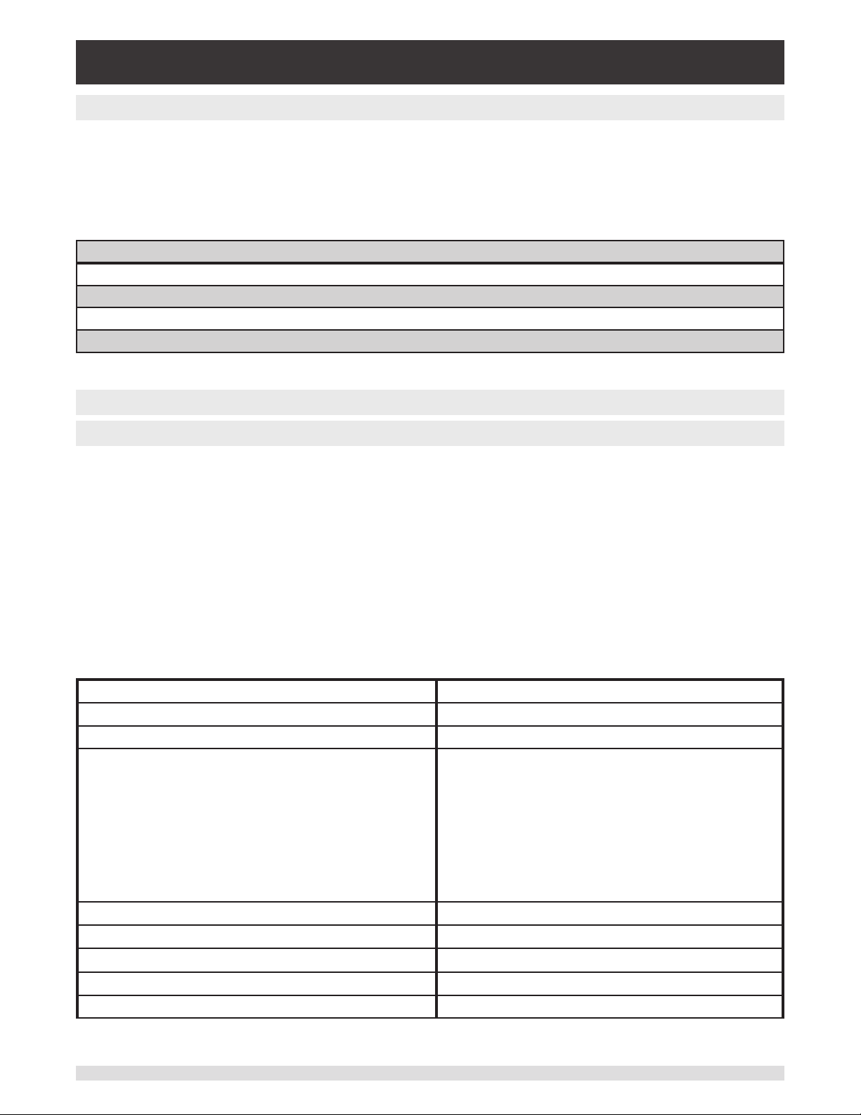
Industrial Pressure Controller
CPC4000
7.5.6 Error Messages
All remote commands sent to the CPC4000 are shown in the Trouble Shooting App, under the “Remote”
button. If there is a syntax error, an error message will appear below the errant command. Local errors
and remote command errors will appear under the “Error” button. Maximum of 100 errors are stored and
can be retrieved.
The error messages can also be seen remotely by sending “Error?” to the instrument.
Error String Returned
NO ERRORS
Parameter error: <s>; where <s> is the input from the remote interface
Syntax error: <s>; where <s> is the input from the remote interface
Command error: zero 10: see: caldisable; occurs when calibration mode is disabled
7.6 SCPI Command Set
7.6.1 SCPI Commands and Queries
The WIKA SCPI command is compatible with older WIKA instruments such as the original CPC8000
Notes:
1. Note that WIKA and Ruska 7010 Emulation return slightly dierent responses to some queries.
2. Except for the engineering units selection, the numeric sux selects the applicable transducer [R]:
1 = Sensor 1
2 = Sensor 2
This numeric sux [R] always defaults to the active transducer if not specied.
Table 7.6.1 - CPC4000 SCPI Command Set
Command Response/Function
STATus
:OPERation
:CONDition? Returns an integer value representing instrument
status that can be decoded.
Bit 0: Zeroing active
Bit 1: Control Setpoint has not been reached.
Bit 2: Reserved 0.
Bit 3: Reserved 0.
Bit 5: Measuring. The instrument is actively measuring
MEASure
[:PRESsure][R]? Returns the pressure from range R
:TEMPerature[R]? Returns the temperature from range R
:RATE[R]? Returns the rate/sec from range R
:BAROmetric? Returns the barometric pressure
80 Operating Instructions - CPC4000
Page 81

Industrial Pressure Controller
CPC4000
CALibration
[:PRESsure][R]
:MODE? Returns 1=calibrated or 0=not calibrated
:DATE? Returns date of cal “MM/DD/YY”
:DATE <i,i,i> Sets date of cal YYYY,MM,DD
:ZERO? Returns zero oset
:ZERO <n> Sets the zero oset
:ZERO:RUN Start Autozero sequence
:ZERO:STOP Stop Autozero sequence
:ZERO:INITiate? Returns zero status
:ZERO:INITiate Ignored
SENSe
[:PRESsure][R]
:NAME? Returns transducer name string
:MODE? Returns “ABSOLUTE” or “GAUGE”
:MODE ABS | GAUGE Sets pressure type
:ABS? Returns native transducer type
0=GAUGE 1=ABSOLUTE
:RESolution? Returns resolution (oat)
:RANGe
[:UPPer]? Returns maximum range
:LOWer? Returns minimum range
:UNIT
[:NAME]? Returns ASCII units (mixed case)
:VALue? Returns the units conversion factor
:REFerence
[:HEIGht] <n> Sets the head pressure height
:HEIGht? Returns the head pressure height
:MODE? Returns “OFF”, “HELIUM”, “DRYAIR”, or
“NITROGEN”
:MODE OFF | HELIUM | DRY
AIR | NITROGEN
:MEDium<n> Sets the medium density
:MEDium? Returns medium
:ACTive <n> Sets the active transducer
ACTive? Returns the active transducer
Sets the head pressure mode
SYS Te m
:DATE <i,i,i> Not used, kept for backwards compatibility
:DATE? Not used, does not cause an error, does not
return a response
:TIME <i,i,i> Not used, kept for backwards compatibility
Operating Instructions - CPC4000 81
Page 82

Industrial Pressure Controller
CPC4000
:TIME? Not used, does not cause an error, dose not
:ERRor[:NEXT]? Returns error code, description
:KLOCk ON | OFF | 1 | 0 Sets the keylock state
:PRESet Load known state values
:SAVe No function (not needed)
:VERSion? Returns SCPI version 1994.0
TEST
:ELECtronic? Returns “OK”
:RELay<n>? Returns status of digital output <n>
:RELay<n> ON | OFF Turns the digital output on or o <n>
UNIT
:[PRESsure] bar | mbar | Pa | psi Sets the pressure units
:[PRESsure]? Returns the pressure units
return a response
:NAME<n>? Returns the units string for units code <n>
:FACTor <n>? Returns the units conversion for units code <n>
:INDEX <n> Sets the index number.
:INDEX? Returns the index number.
index unit
0 bar
1 mbar
2 Pa
3 psi
4 atm
5 kp/cm2
6 lbf/ft2
7 kPa
8 cmH2O(4°C)
9 inH2O(4°C)
10 inH2O(60°F)
11 ftH2O(4°C)
12 µmHg(0°C)
13 mmHg(0°C)
14 cmHg(4°C)
15 inHg(0°C)
16 inHg(60°F)
17 - -
18 user
19 user
20 user
index unit
21 OSI
22 TSI
23 TSF
24 ftH2O(20°C)
25 ftH2O(60°F)
26 inSW
27 ftSW
28 hPa
29 Mpa
30 dyn/cm2
31 mHg 0°C
32 Torr
33 mTorr
34 uHg 0°C
35 mmH2O 4°C
36 mH2O 4°C
37 mmH2O 20°C
38 cmH2O 20°C
39 mH2O 20°C
40 mSW
41 g/cm2
42 Kg/m2
OUTPut
82 Operating Instructions - CPC4000
Page 83

Industrial Pressure Controller
CPC4000
:STATe ON | OFF | 1 | 0 ON or 1 = Control OFF or 0 = Measure
:STATe? Returns 0 for measure 1 for control
:MODE MEASure | CONTrol | VENT Sets the mode indicated
:MODE? Returns the mode string
:STABle? Returns 1 if stable 0 if not
:AUTOvent ON | OFF | 1 | 0 Autovent is always true on CPC4000
:AUTOvent? Returns the state of the Vent mode
:AUTORange ON | OFF | 1 | 0 Turns autorange on or o
:AUTORange? Returns “ON” or “OFF”
[SOURce]
:PRESsure
[:LEVel]
[:IMMediate]
CALCulate
:LIMit
:SYSTem
[:AMPLitude] <n> Sets the setpoint
[:AMPLitude]? Returns the setpoint
:RSETPT <n> Sets the rate setpoint in current units
:RSETPT? Returns the rate setpoint in current units
:SLEW <n> Sets the rate setpoint in %FS/sec
:SLEW? Returns the rate setpoint in %FS/sec
:TOLerance? Returns the stable window
:TOLerance<n> Sets the stable window
:LOWer<n> Set the minimum control limit
:LOWer? Set the minimum control limit
:UPPer<n> Set the maximum control limit
:UPPer? Set the maximum control limit
:DETECT SLOW | FAST | CANCEL Not used, kept for backwards compatibility
:DETECT? Returns “0”
7.6.2 Error Messages
All remote commands sent to the CPC4000 are shown in the Trouble Shooting App, under the “Remote”
button. If there is a syntax error, an error message will appear below the errant command. Local errors
and remote command errors will appear under the “Error” button. Maximum of 100 errors are stored and
Operating Instructions - CPC4000 83
Page 84

Industrial Pressure Controller
CPC4000
can be retrieved.
The error messages can also be seen remotely when “SYST:ERR?” is sent any error in the error queue is
returned, otherwise the following is returned: 0,“No Error”.
Error String Returned
0, “No error”
1,”Overow”
102, “Syntax error”
114,”Parameter Out Of Range”
500,”<s>” (where <s> is the undened error error string generated by the pneumatic module)
602,”Sensor not available”
999,”<s>” (where <s> is the undened (unique) error string)
84 Operating Instructions - CPC4000
Page 85

Industrial Pressure Controller
CPC4000
7.7 DPI 510 Emulation Command Set
The CPC4000 will accept and respond to Druck Model DPI 510 remote commands over a GPIB as listed
below. These commands can be sent individually, or ganged together. Delimiters (separators) between
commands are not required.
7.7.1 DPI 510 Supported Commands and Queries
Table 7.7.1 - DPI 510 Supported Commands and Queries
case ‘#’:
usage “#L{nn}” Simulate GPIB listener at address nn over serial port. Does not support
multidrop.
usage “#T{nn}” Simulate GPIB talker at address ad over serial port. Does not support
multidrop.
case ‘@’: /*Error Status (on/o)*/
usage “@0” sets error checking o
usage “@1” sets error checking on
case ‘C’: /*Control_Mode / Measure_Mode*/
usage “C0” go to measure mode
usage “C1” go to control mode
usage “C2” go to standby mode
case ‘D’: /*Display_Mode*/
usage “D0” returns active reading in any mode
usage “D1” returns setpoint only if in control mode, otherwise it returns 0.000
case ‘E’: /*Clear_Error_Mode*/
usage “E” The PCS 400 will accept all types of termination; CR/LF/EOI. It will also
accept the strings E0, E1 and E2, but will not respond to these.
Note: Send “E?” to clear an error from the buer (this is an added function, not part of the
Druck command set).
case ‘F’: /*Function*/
usage “F00” does not apply to CPC4000
usage “F01” puts instrument into vent mode when C0 or controller is o
usage “F02” does not apply to CPC4000
usage “F03” does not apply to CPC4000
case ‘I’: /*IO Service Request*/
usage “I0” dummy function accepts the string and returns what was entered
usage “I1” dummy function accepts the string and returns what was entered
usage “I2” dummy function accepts the string and returns what was entered
usage “I3” dummy function accepts the string and returns what was entered
usage “I4” dummy function accepts the string and returns what was entered
usage “I5” dummy function accepts the string and returns what was entered
usage “I6” dummy function accepts the string and returns what was entered
case ‘J’: /*Rate_Mode*/
usage “J0” sets the rate mode to variable rate mode
Operating Instructions - CPC4000 85
Page 86
Industrial Pressure Controller
CPC4000
usage “J1” sets the rate mode to variable rate mode
usage “J2” sets the rate mode to regular control mode (default) MAX
Note: All of the notation formats have a leading space!
case ‘N’: /*Notation_Mode*/
usage “N0” output format default responds with pressure/remote/range/scale/dis-
play/error
usage “N1” output format responds with pressure or setpoint depending on the
display mode setting
usage “N2” output format responds with range/scale/display/control mode/IO/func-
tion/error
usage “N3” output format returns 0 for not stable or 1 for stable
usage “N4” output format returns error/error(on/o)/rate/variable rate/units
N0 if display is set to 1 the pressure reading is the setpoint reading
example 200.00REMR1S3D1@01
if display is set to 0 the pressure reading is the pressure reading
example 199.98REMR1S3D0@01
N1 if display is set to 1 the pressure reading is the setpoint reading
example 200.00
if display is set to 0 the pressure reading is the pressure reading
example 199.98
N2 example R1S3D1C0I0F00@01
N3 example 1
N4 @01@1J0V+00009U BAR
case ‘P’: /*Pressure_Setpoint_Mode*/
usage “PXXXX.
XXXX”
case ‘R’: /*Range(xducer)*/
usage “R0” no range
usage “R1” range 1 if available (main range)
usage “R2” range 2 if available (secondary range)
case ‘S’: /*Scale*/
usage “S1” sets the scale with one unit selection
usage “S2” sets another scale with another unit selection
usage “S3” sets the global scale enables all units to be selected
case ‘U’: /*Units*/
usage “UX” X = the unit number (ex. U16 = psi)
case ‘V’: /*Variable_Rate_Mode*/
usage “VXXXXX” X = the desired control rate setting (ex. V1)
case ‘W’: /*Wait_Value_Mode*/
usage “WXXX” X = the desired stable delay setting in seconds (ex. W005 = 5 sec)
X = sets the pressure setpoint (ex. P13.5)
86 Operating Instructions - CPC4000
Page 87

Industrial Pressure Controller
CPC4000
7.7.2 DPI 510 Unsupported Commands and Queries
Table 7.7.2 - DPI 510 Unsupported Commands and Queries
usage “A” does nothing
usage “E “ does nothing
usage “O” Zeroing, software will accept the command but does not
aect the zero status of the instrument
usage “R0” setting remote to local
usage “R1” setting to remote
usage “I0” does nothing
usage “I1” does nothing
usage “I2” does nothing
usage “I3” does nothing
usage “I4” does nothing
usage “I5” does nothing
usage “I6” does nothing
UNITNO 7 (kg/m2) does nothing
UNITNO 10 (mHg) does nothing
UNITNO 17 (lb/ft2) does nothing
UNITNO 21 (Special) does nothing
Operating Instructions - CPC4000 87
Page 88

Industrial Pressure Controller
CPC4000
7.7.3 DPI 510 Measurement Units
The Measurement units below use conversion factors as listed in this manual’s Appendix:
Table 7.7.3 - DPI 510 Measurement units
Druck Unitno Units Comments
1 Pa
2 kPa
3 mPa
4 mbar
5 bar
6 kg/cm2
7 kg/m2 not supported
8 mmHg
9 cmHg
10 mHg not supported
11 mmH2O
12 cmH2O
13 mH2O 20c
14 torr
15 Atm
16 psi
17 1b/ft2 not supported
18 inHg
19 “H2O 04c
20 ‘H2O 04c
21 Special not supported
22 “H2O 20c
23 ‘H2O 20c
88 Operating Instructions - CPC4000
Page 89

Industrial Pressure Controller
CPC4000
7.8 GE PACE (SCPI) Emulation Command Set
The CPC4000 will accept and respond to the SCPI remote commands of GE PACE 5000/6000 remote
commands using the option SCPI_GE. Section 11, Technical Assistance explains the process of enabling the SCPI GE command set. Table 7.8.1 shows a complete list of supported commands.
7.8.1 SCPI GE Supported Commands and Queries
Table 7.8.1 SCPI GE Supported Commands and Queries
Command Response/Function
CALCulate
[:LIMit]
:LOWer<n> Set the minimum control limit *
:LOWer? Set the minimum control limit *
:UPPer<n> Set the maximum control limit *
:UPPer? Set the maximum control limit *
CALibration
[:PRESsure][R]
:POINt? Returns the number of calibration points used in
the active sensor’s linearity correction. Calibration functionality must be enabled by sending the
calibration password. See SYST:PASS:CEN
:ZERO
:AUTO Start autozero process
:AUTO? Returns 1 if autozero process is running, 0 other-
wise
VALVe ON | OFF | 1 | 0 ON or 1 puts in vent mode, OFF or 0 puts in mea-
sure mode
:VALVe? Returns 1 if in vent mode, 0 otherwise
INPut
:LOGic? Returns a single digit number that is a mask
of the digital input states, i.e. a number of 7 in
binary is 111 which indicates all digital inputs are
on. Then current pressure reading.
Ex// INP:LOG?
:INP:LOG 7, 14.50021
:STATe? Returns a single digit number that is a mask
of the digital input states, i.e. a number of 7 in
binary is 111 which indicates all digital inputs are
on.
Ex// INP:LOG:STAT?
:INP:LOG :STAT 0
Operating Instructions - CPC4000 89
Page 90

Industrial Pressure Controller
CPC4000
INSTrument
:CATalog[R]? Returns the sensor pressure maximum in native
units, native pressure units, native pressure type.
Ex// INST:CAT?
:INST:CAT “1000.000psig”
:CATalog
:ALL? Returns the primary sensor’s pressure maximum
in native units, native pressure units, native pressure type, secondary sensor’s pressure maximum in native units, native pressure units, native
pressure type, Barometer. If a sensor does not
exist, it is not included.
Ex// INST:CAT:ALL?
:INST:CAT “1000.000psig”, “300.0000psig”,
BAROMETER
:LIMits? Returns the instrument’s pressure maximum in
native units, native pressure units, native pressure type, current upper control limit, current
lower control limit.
Ex// INST:LIM?
:INST:LIM “1000.000psig”, 1000.000,
-15.0000
:MACaddress? Returns the ethernet interface medium access
control (MAC) hardware address in XX-XX-XXXX-XX-XX format. Any letters will be upper case.
Ex// :INST:MAC?”
:INST:MAC ”84-EB-18-B2-97-AB”
:SENSe[R]? Returns the sensor pressure maximum in native
units, native pressure units, native pressure type.
Ex// INST:SENS?
:INST:SENS “1000.000psig”
:SENSe[R]
:CALD? Returns the sensor calibration date in the format
YYYY, MM, DD
:FULLscale? Returns the sensor maximum pressure, minimum
pressure in active units
:NEGCal? Returns 1. Negative calibration support is always
available
:SN? Returns the sensor serial number
90 Operating Instructions - CPC4000
Page 91

Industrial Pressure Controller
CPC4000
:SN[N]? Returns the serial number of device N. When N
is not specied, default is 1. If the device does
not exist, 0 is returned.
N Device
1 Instrument
2 Regulator
3 0
4 0
5 0
6 0
7 0
:TASK? Returns the active task set remotely. The short
string format is returned.
BAS (BASIC)
BURST (BURSTTEST)
DIV (DIVIDER)
LEAK (LEAKTEST)
PRE (PRESET)
SWITCH (SWITCHTEST)
PROG (TESTPROGRAM)
:TASK <CCC> Set the instrument task. Either the long or short
version may be sent. Makes the active screen on
the instrument be loaded. Loading a new task will
force any other tasks being run to be stopped.
Does not put the screen in keylock mode.
BAS/BASIC – loads home application
BUR/BURST/BURSTTEST – loads burst test application
DIV/DIVIDER – loads step settings application
LEAK/LEAKTEST – loads leak test application
PRE/PRES/PRESET – loads step settings application
SWI/SWITCH/SWITCHTEST – loads switch test
application
PROG/TEST/TESTPROGRAM – loads the programs application
:UNIT? Returns the active units string.
Ex// INST:UNIT?
:INST:UNIT PSI
Operating Instructions - CPC4000 91
Page 92
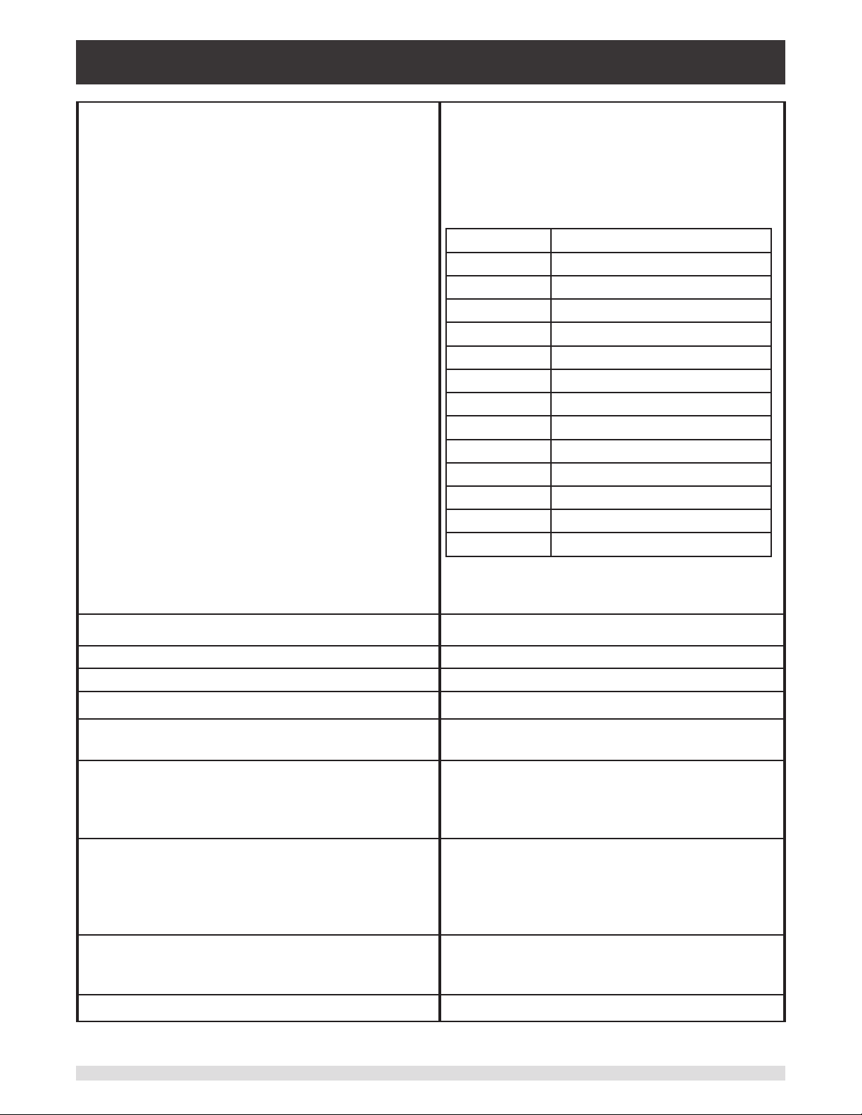
Industrial Pressure Controller
CPC4000
:VERSion[n]? Returns the software version of the device N in
double quotes. When N is not specied, default
is 1.
Ex// INST:VERS2?
:INST:VERS “v1.2”
N Device
1 Instrument Software
2 Operating System (OS)
3
4 Regulator PIC
5 Regulator FPGA
6
7
8 Sensor 1
9 Sensor 2
10
11
12 Barometer
13 GPIB
Ex// INST:VERS?
:INST:VERS “v2.27.0“
OUTPut
[:ISOLation]
:STATe? Returns 1 if in Measure mode, 0 otherwise
:STATe ON | OFF | 1 | 0 ON or 1 puts in Measure mode, 0 puts in Vent
mode
:LOGic? Returns a single digit number that is a mask of
the digital output states, e.g. a number of 7 in
binary is 111 which indicates all digital outputs
are on
:LOGic Set the digital outputs with a mask (number
from 0 to 7 for setting the three outputs). Note:
the digital output functions will be automatically
changed to “USER” and show up as “None” in the
Application screen
:MODE Measure | Control | Vent Sets the mode indicated. May use as low as 1
character in the data, i.e. ‘V’ for Vent, or ‘VENT’
for vent, etc.
:MODE? Returns the mode string
92 Operating Instructions - CPC4000
Page 93

Industrial Pressure Controller
CPC4000
:STABle? Returns 1 if in Control mode and pressure is
stable, 0 otherwise
:STATe ON | OFF | 1 | 0 ON or 1 puts in Control mode , OFF or 0 puts in
Measure mode
[:STATe]? Returns 1 if in Control mode, 0 otherwise
SENSe
[:PRESsure][R]
:BARometer? Returns the current barometer reading in active
channel’s units
:CORRection
:OFFSet? Returns the tare value in current units
:OFFSet <f> Set the head pressure correction value in current
units
:OFFSet
:STATe? Returns 1 if the tare value is currently enabled, 0
if not.
:STATe ON | OFF | 1 | 0
:HEAD? Returns the gas type, current head pressure cor-
rection in current units for the active channel. Ex//
SENS:PRES:CORR:HEAD?
:SENS:PRES:CORR:HEAD DRY AIR,
0.000000
:HEAD <”CCC”, f> Set the gas type and head pressure correction
value in current units. Requires the gas type(CCC
= AIR, HELIUM, NITROGEN) in double quotes,
numeric value (oat)
:STATe? Returns 1 if the head pressure correction is cur-
rently enabled, 0 if not.
:STATe ON | OFF | 1 | 0 Enable or disable the head pressure correction
:VOLume? Returns the calculated volume by the regulator
in cubic centimeters. This value is constantly
changing while in control mode
:VOLume
:VALue? Returns the regulator control volume. May be
AUTO or a number in cubic centimeters
:VALue <f> Set the regulator control volume to AUTO or a
number (0 to 1000 for a pump, 0 to 2000 for a
SVR)
:FILTer
[:LPASs]
Operating Instructions - CPC4000 93
Page 94

Industrial Pressure Controller
CPC4000
:STATe? Returns if the lter is enabled (0 is o, 1 is on)
:STATe ON | OFF | 1 | 0 Set the lter enable
:BAND? Returns the lter window
:BAND <f> Set the lter window
:FREQuency? Returns the lter frequency
:FREQuency <f> Set the lter frequency
:INLimits? Returns current pressure reading (oat), stable
:INLimits
:TIME? Returns the stable delay in seconds
:TIME<f> Set the stable delay in seconds
:RANGe? Returns primary sensor maximum pressure,
:RESolution? Returns sensor resolution (integer 4 to 6)
:RESolution <n> Set the sensor resolution
ag (0 not stable, 1 stable)
units, and pressure type, i.e. “1000.000psig”
SOURce
[:PRESsure]
:SLEW? Returns the rate in current units
[:LEVel]
[:IMMediate]
[:AMPLitude]? Returns the setpoint in current units
[:AMPLitude] <f> Sets the setpoint in current units
:VENT? Returns 1 if in vent mode and pressure is not fully
vented (stable) yet, 0 otherwise. Proper usage:
put in vent mode, then query this value until it is 0
again to know the system is vented.
:VENT ON | OFF | 1 | 0 ON or 1 puts in vent mode , OFF or 0 puts in
Measure mode
:SLEW? Returns the rate setpoint in current units
:SLEW <f> Sets the rate setpoint in current units
:SLEW
:MODe? Returns MAX when highspeed mode is active.
Returns LIN otherwise.
:MODe <CCC> Set the control mode by putting in either High-
speed or Custom mode. Note: the overshoot ag
and control mode are not independent in Mensor
products.
:OVERshoot? Returns 1 if the channel’s control behavior is >50.
Returns 0 if the control behavior <=50.
94 Operating Instructions - CPC4000
Page 95

Industrial Pressure Controller
CPC4000
:OVERshoot ON | OFF | 1 | 0 ON or 1 puts in “overshoot allowed” mode, where
if the control behavior <90, it will be set to 100.
OFF or 0 puts in low overshoot mode, where if
the control behavior is >10, it will be set to 10.
:TOLerance? Returns the stable window *
:TOLerance<n> Sets the stable window *
:COMPensate? Returns 0.0. Note: Mensor products do not have
a source pressure sensor. †
:EFFort? Returns the current channel’s regulator output,
which is a number between -100 to +100 indicat-
ing how much % eort the regulator is using to
achieve the setpoint.
STATus
:[OPERation]? Returns 0
:[OPERation]
: CONDition? Returns 0
: EVENt? Returns 0
[:QUEStionable]? Returns 0
[:EVENt]? Returns 0
[:ENABle]? Returns 0
SYS Te m
:AREA? Returns the system locale area.
:AREA Set the system locale area. Accepts the following
(lower case letters are not required):
EURope
JAPan
USA
ASIA
ROW (abbreviation for Rest of World)
:DATE? Returns the system date in YY, MM, DD format
:DATE <i,i,i> Set the system date
:PASSword
:CEN Enter the calibration password to enable calibra-
tion functionality. Applies to the entire instrument
device. Once enabled, cannot be disabled until a
power cycle. Calibration password is 2317100
:TIME? Returns the system time in HH, MM, SS
Operating Instructions - CPC4000 95
Page 96
Industrial Pressure Controller
CPC4000
:TIME <i,i,i> Set the system time
:ERRor? Returns error code, description
:KLOCk? Returns if keylock state
:KLOCk ON | OFF | 1 | 0 Sets the keylock state
:COMMunicate
:USB? Returns COMM
:SERial
:BAUD? Returns the serial communication baud rate
:BAUD Set the serial communication baud rate
:CONTrol? Returns 0
:CONTrol
:RTS? Returns 0
:RTS <n> Accepts 0. All other values generate a parameter
error (only ow control none is supported).
:XONX? Returns 0
:XONX Accept 0. All other values generate a parameter
error (no handshaking modes supported).
:TYPE
:PARity? Returns the serial communication parity bit set-
ting (NONE, EVEN, ODD)
:PARity <CCC> Set the communication parity setting to NONE,
ODD, or EVEN
:GPIB
: SELF
:ADDRess? Returns the GPIB address
:SET? Returns VENT, 0.0
:SET Only accepts Vent, 0. Not allowed to boot up a
Mensor product in any mode except vent mode
with a setpoint of 0 for safety reasons.
UNIT
:[PRESsure] <c> Sets the pressure units. Accepts the unit code
number, or the string value representation, i.e.
psi.
See unit code table below.
:[PRESsure]? Returns the pressure units string
:DEFine[N]? Returns the user dened units name, multiplica-
tion factor. Index N is 1 or 2.
96 Operating Instructions - CPC4000
Page 97

Industrial Pressure Controller
CPC4000
:DEFine[N] <”CCC”, f> Sets the user dened units for index N. If N is not
sent, will default to user units 1. Requires the desired unit name in double quotes, multiplication
factor from Pascal (base units is always Pascal).
Index N is 1 or 2
7.8.2 Error Messages
All remote commands sent to the CPC4000 are shown in the Trouble Shooting App, under the “Remote”
button. If there is a syntax error, an error message will appear below the errant command. Local errors
and remote command errors will appear under the “Error” button. Maximum of 100 errors are stored and
can be retrieved.
The error messages can also be seen remotely when “SYST:ERR?” is sent any error in the error queue is
returned, otherwise the following is returned: 0,“No Error”.
Error String Returned
0, “No error”
1,”Overow” (occurs when remote interface buer of commands has become full. Command will not be
processed)
102, “Syntax error”
102,”Syntax error;Unbalanced string.”
105,"Parameter not supported, parameter 1"
105,”Parameter not supported, parameter 2”
108,”Parameter not allowed”
109,”Missing parameter”
113,”Undened header”
113,”Command Unknown”
114,”Parameter Out Of Range”
114,”Header sux out of range”
131,”Invalid sux;Unit sux not dened.”
200,”Execution error;Query or command violation”
200,”Execution error;Type mismatched, parameter 1”
200,”Execution error;Type mismatched, parameter 2”
203,”Access error; Incorrect password”
220,”Parameter error”
240,”Hardware error
500,”<s>” (where <s> is the undened error error string generated by the pneumatic module)
201,”Query only”
207,”Enumeric value not in union”
602,”Sensor not available”
999,”<s>” (where <s> is the undened (unique) error string)
Operating Instructions - CPC4000 97
Page 98

Industrial Pressure Controller
CPC4000
7.9 USB Software Upgrade
The instrument software can be upgraded to the most recent release by copying the instrument software
from the Mensor website onto a USB device. The instrument software is device specic and the software
for any other instrument apart from the CPC4000 is not accepted by the instrument. The user can then
plug the USB device to the USB port on the front panel of the instrument for an easy upgrade. The instru-
ment recognizes this device by displaying a USB icon on the top bar of the screen (gure 7.10). The user
can navigate to the Software upgrade menu by clicking on the USB icon. The software upgrade menu
gives the user information on the current instrument software and the version of instrument software on
the USB device (gure 7.10-A).
The user can load the instrument software from the USB to the instrument by clicking on the desired version and then clicking [ ] button. The status of the installation can be seen on right one fourth of the
screen.
The user also has the option to copy and load program test sequences (gure 7.10-B) from the USB
drive which can later be accessed through the Programs App menu. Figure 7.10-C shows how to safely
remove the USB drive.
Figure 7.10 – Home App with USB Icon Figure 7.10-A – Software Upgrade Menu
Figure 7.10-B – Copy Programs Figure 7.10-C – Remove USB Device
98 Operating Instructions - CPC4000
Page 99

Industrial Pressure Controller
CPC4000
8 Options
• Barometric Reference Transducer (for gauge and absolute emulation)
• Additional Transducers (spare or alternate range)
• Rack Mount Kit
• Fittings
• Remote calibrations sleds (for transducers and/or barometric reference)
• Automatic Contamination Prevention System
• Contamination Prevention Accessories
• Pressure Booster
8.1 Barometric Reference (CPX-A-C4-6)
The CPC4000 can be ordered with a barometric reference transducer. It is a very stable, absolute pressure transducer used to accurately measure local atmospheric pressure. It is used to display the barometric pressure (reading appears on the bottom right side of the display) or as a barometric reference for
gauge or absolute emulation.
This transducer is in a dierent housing compared to the regular transducers. It is removable by taking o
the top cover of the chassis.
8.1.1 Gauge Pressure Emulation
In the Home Application (main screen) an absolute transducer channel will indicate “Absolute” in the
Pressure Type button (this is the default mode). When the Pressure Type button is pressed the button label will toggle to “Gauge” and have a lighter background color. The lighter background color is an indication that the channel is in emulation mode.
In the gauge emulation mode the atmospheric pressure reading from the barometric reference transducer is subtracted from the absolute pressure reading to emulate a gauge pressure.
The barometric reference transducer has six signicant digits. If a very low pressure gauge transducer
is active and is used in absolute emulation, the combined output may appear quite noisy because of the
resolution of the barometric reference.
8.1.2 Absolute Pressure Emulation
In the Home Application (main screen) a gauge transducer channel will indicate “Gauge” in the Pressure
Type button (this is the default mode). When the Pressure Type button is pressed the button label will
toggle to “Absolute” and have a lighter button background color. The lighter background color is an indication that the channel is in emulation mode.
In the absolute emulation mode the atmospheric pressure reading from the barometric reference transducer is added to the gauge pressure reading to emulate an absolute pressure.
8.1.3 Emulation Mode Accuracy
The accuracy in emulation mode is dierent for gauge and absolute emulation mode.
The barometric reference has six signicant digits and has a guaranteed drift of 0.0000041 psi over a 24
hour period which has no signicant eect on the emulated gauge pressure uncertainty.
The absolute uncertainty of the barometric reference must be considered in the emulated absolute pressure uncertainty.
Operating Instructions - CPC4000 99
Page 100

Industrial Pressure Controller
CPC4000
8.1.4 Barometric Reference Calibration
The Barometric Reference Transducer can be calibrated in exactly the same manner as the other
installed transducers as described in Section 10, Calibration.
8.1.5 BarometricReferenceSpecications
Accuracy: 0.02% of reading. Uncertainties include all pressure eects and temperature eects over the
calibrated range and calibration stability for 365 days after re-zeroing.
Pressure Range: The standard Barometric Reference Transducer is calibrated from 8 to 17 psia.
Resolution: 6 digits
8.2 Additional Transducers (CPR4000)
A secondary transducer of any standard range, can be purchased as an option. In all other regards, the
add-on transducer will meet all of the specications and operating parameters outlines throughout this
manual.
CAUTION: Typically, the pressure regulator in each instrument has limits of 50,
150, 1500 or 3,045 psig. If a transducer is placed into an instrument where the
!
Caution
transducer has a higher upper pressure range than the instrument’s regulator, the
maximum control limit will be limited to the maximum range of the instrument’s
regulator.
While any transducer will function in any instrument, the results may not always be optimum. For example, if a 1 psi transducer is placed in an instrument that has a 1500 psi upper limit, the controlled pressure
stability may not be acceptable. Or if a 1500 psi transducer is placed in an instrument that has a 30 psi
upper limit, it will control very well, but be limited in resolution.
8.2.1 Secondary Transducer Installation
If the add-on transducer is of a higher full scale range than the existing primary transducer, then this
newer transducer becomes the Primary, and the existing transducer must be moved to the Secondary
Transducer slot. For complete installation instructions see Section 9.3 ,Transducer Removal.
8.3 Rack Mount Kit (CPX-A-C4-R)
A rack mount kit allows the customer to install a CPC4000 into a standard 19” instrument rack. It includes
a tray and a cover panel for the front. The instrument will rest on the tray and be retained by the panel.
Figure 8.3 – Rack Mount Kit
100 Operating Instructions - CPC4000
 Loading...