

Page 1
Industrial Pressure Controller
Model CPC4000
Applications
■
Oil & gas industry
■
Industry (laboratory, workshop and production)
■
Transmitter and pressure gauge manufacturers
■
Calibration service companies and service industry
Special Features
■
Pressure ranges -1 ... 210 bar (-15 ... 3,045 psi)
■
Control speed of 10 s
■
Control stability < 0.005 % FS
■
Accuracy down to 0.02 % IS (IntelliScale)
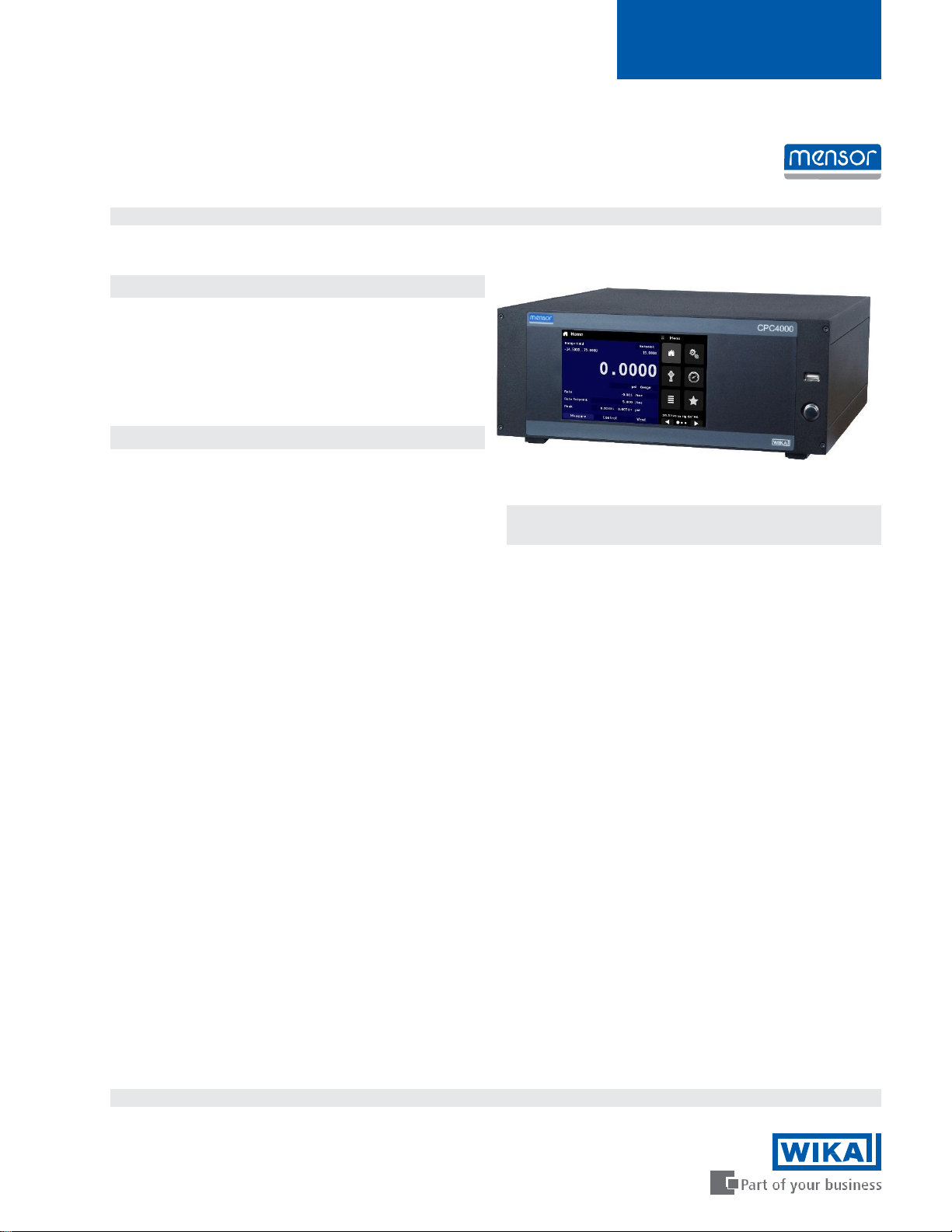
Description
Design
The CPC4000 offers a broad pressure range from -1 …
210 bar (-15 … 3,045 psi). This instrument can be
specified as a desktop or as a 19” rack-mounted device.
It can have up to two reference pressure sensors and
an optional barometer for displaying barometric
pressure or used to emulate gauge or absolute
pressure.
Application
Since the controller offers a measurement accuracy of
up to 0.02 %IS-50, and controls pressure with a high
stability, it is particularly suited as a production tool for
transmitter manufacturing, a calibration and
maintenance tool for pressure measuring devices or a
factory/working standard for the calibration of all types of
pressure measuring devices. The contamination
prevention accessories like the coalescing filter and
block and bleed valve make the CPC4000 an ideal
solution in oil and gas plants.
Functionality
The touchscreen, along with an intuitive user interface,
provide maximum ease-of-use. In addition, the large
number of menu languages add to its operability. The
device can have up to two internal pressure transducers
and the ranges for each unit are determined by the
customer within the allowable range.
Calibration Technology
Calibration technology
WIKA data sheet CT 27.40
Industrial Pressure Controller
Model CPC4000
Depending on the application, the operator can choose
between three methods of pressure control:
1) Direct numeric entry via keypad for the precise input of
the pressure value (set point) which will be controlled.
2) Define steps to reach the desired pressure value by
either defining fixed pressure increments or a
percentage of span value.
3) Program and store individual test sequences based on
users’ application.
Software
The WIKA-CAL calibration software enables the convenient
calibration of pressure measuring instruments and the
generation of test certificates. Additionally the device can
also be remotely controlled using the serial command
formats, the Mensor standard, SCPI or further optional
command sets are available.
Complete Test and Calibration Systems
On request, complete mobile or stationary test systems can
be manufactured. There is an IEEE-488.2, RS-232, USB
(along with an optional USB-WiFi adapter) and an Ethernet
interface for communication with other instruments, and
thus the instrument can be integrated into existing systems.
WIKA data sheet CT 27.40 ∙ 04/2015
Data sheets showing similar products and accessories:
Pneumatic precision pressure controller; model CPC6000; see data sheet CT 27.61 High-end
pressure controller; model CPC8000; see data sheet 28.01
WIKA-CAL calibration software; see data sheet CT 95.10
Page 1 of 8
Page 2

Specifications
CPC4000
Reference Pressure Sensors
Pressure range Standard Optional
Accuracy
Gauge pressure 0 ... 0.35 up to 0 ... 210 bar
Bi-directional -0.35 ... 0.35 up to -1 ... 210 bar
Absolute pressure 0 ... 1 up to 0 ... 211 bar abs.
1)
0.02 % FS 0.02 % IS-50
2)
0 ... 1 up to 0 ... 210 bar
(0 ... 5 up to 0 ... 3,045 psi)
(0 ... 15 up to 0 ... 3,045 psi)
-1 ... 10 up to -1 ... 210 bar
(-5 ... 5 up to -15 ... 3,045 psi)
(-15 ... 145 up to -15 ... 3,045 psi)
0 ... 1 up to 0 ... 211 bar abs.
(0 ... 15 up to 0 ... 3,060 psi abs.)
(0 ... 15 up to 0 ... 3,060 psi abs.)
Calibration interval 365 days 365 days
Optional barometric reference
Function The barometric reference can be used to switch pressure types 3), absolute <=> gauge. With gauge
pressure sensors, the measuring range of the sensors must begin with -1 bar (-15 psi) in order to carry
out an absolute pressure emulation.
Measuring range 552 ... 1,172 mbar abs. (8 ... 17 psi abs.)
Accuracy
1)
0.02 % of reading
Pressure units 38 and two freely programmable
1) It is defined by the total measurement uncertainty, which is expressed with the coverage factor (k=2) and includes the following factors: the intrinsic performance of the instrument, the
measurement uncertainty of the reference instrument, long-term stability, influence of ambient conditions, drift and temperature effects over the compensated range during a periodic zero
point adjustment.
2) 0.02 % IS-50 accuracy: 0.02 % of reading in the upper half of the measuring range.
3) For a pressure type emulation, we recommend a native absolute pressure sensor, since the zero point drift can be eliminated through a zero point adjustment.
Base Instrument
Instrument
Instrument version Standard: desktop case
Option: 19" mounting with rack-mounting kit
Dimensions in mm see technical drawings
Weight approx. 12.7 kg (28 lbs.) with all internal options
Warm-up time approx.. 15 min
Display
Screen 7.0" color LCD display
Resolution 4 ... 6 digits depending on range and units
Input methods Resistive touchscreen
Connections
Pressure connections 4 ports with 7/16”- 20 F SAE and 1 port with 1/8” F NPT
Optional Barometer: 1 port with barb fitting
Filter elements Filter element (40 micron) included in each pressure port
Pressure port adapters Standard: without
Option: 6 mm tube fitting, 1/4" tube fitting, 1/4" NPT female, 1/8" NPT female or 1/8" BSPG female
Permissible pressure and media
Permissible pressure media Dry, clean air or nitrogen (ISO8573-1:2010 Class 5.5.4 or better)
Wetted parts Aluminum, bras s, 316 and 316L stainless steel, Buna N, FKM/FPM, PCTFE, PEEK, PTFE, PPS,
glass-filled epoxy, RTV, ceramic, silicone, silicone grease, Urethane
Overpressure protection Safety relief valve adjusted to specific customized pressure range
Supply Port ~ 110 % FS
Measure/Control Port max. 105 % FS
Page 3

Base Instrument
Power supply
Power supply AC 100 ... 240 V, 50 Hz / 60 Hz
Power consumption max. 120 VA
Permissible ambient conditions
Storage temperature 0 ... 70 °C (32 ... 158 °F)
Humidity 5 … 95 % r. h. (relative humidity, non-condensing)
Compensated temperature range 15 … 45 °C (59 ... 113 °F)
Mounting position horizontal
Control parameter
Control stability < 0.005 % FS of active range
Control mode Slow, normal, fast and variable
Control time 10 s (with a 10% pressure increase in a 50cc test volume)
Control range 0.05% FS or 0.0017 bar (0.025 psi) over exhaust pressure to 100% FS
Overshoots < 0.3% FS in fast control mode (typical <0.1% FS in slow control mode)
Test volume 50 ... 1,000 ccm
Communication
Interface Standard: Ethernet, IEEE-488, USB, RS-232.
Command sets Mensor, WIKA SCPI, others optional
Response time 100 ms
Optional: WiFi (with a USB-WiFi adapter)
Approvals and Certificates
CE conformity
EMC directive
Low voltage directive 2006/95/EC, EN 61010-1:2010
Approvals
GOST Metrology/measuring technology, Russia
Certificate
Calibration
4) Warning! This is class A equipment for emissions and is intended for use in industrial environments. In other environments, e.g. residential or commercial installations, it can interfere with
other equipment under certain conditions. In such circumstances the operator is expected to take the appropriate measures.
5) Calibration in a horizontal position.
5)
6)
2004/108/EC, EN 61326-1: 2013 emission (group 1, class A) and interference immunity (industrial
application)
Standard: A2LA calibration certificate (standard on factory)
Option: DKD/DAkkS calibration certificate
Approvals and certificates, see website
Page 4

LPSVR MODULE ±0.175 bar (±2.5 psi)
2)
MPSVR MODULE ±0.7 bar (± 5 psi)
2)
HPSVR 3) MODULE -1… 5.2 bar (-15 … 75 psi)
2)
EPSVR
3)
MODULE -1 ... 10 bar (-15 … 150 psi)
2)
LPSVR MODULE 0 … 0.5 bar (0 … 7.5 psi)
2)
MPSVR MODULE 0 … 1 bar (0 … 15 psi)
2)
HPSVR 3) MODULE 0 … 5.2 bar (0 … 75 psi)
2)
EPSVR
3)
MODULE 0 ... 11 bar (0 … 165 psi)
2)
Working Ranges of the Controller Modules
Bi-directional or gauge pressure [bar (psi)]
-1 (-15) 0 3.4 (50) 10 (150) 100 (1,500) 210 (3,045)
Absolute pressure [bar (psi)]
0 4.4 (65) 11 (165) 101 (1,515) 211 (3,060)
1)
1)
1) Mixing of absolute pressure and gauge pressure sensors in a module is not possible.
2) Smallest recommendable sensor range
For controlling absolute pressure a vacuum pump connected at the Exhaust port is required.
Easy Operation via Touchscreen
Home Screen
Shortly after power-up, the standard home screen (see following picture) is displayed. In this menu screen, one can switch
between the operating modes using the buttons “MEASURE” / “CONTROL” / “VENT” at the bottom of the screen.
Set point selection
Selection of the active sensor
or auto-range
Range of sensors
Optional zero/ tare function
Current measuring value
Optional bar graph
Current pressure unit
Auxiliary displays with either
Pressure mode, peak, rate or
alternate units
MEASURE
In measure mode, the pressure
present at the Measure/Control port
is measured with high accuracy (if
you switch directly from
“CONTROL” to “MEASURE” mode,
the last controlled pressure in the
connected test assembly will be
maintained/locked).
CONTROL
In control mode, the
instrument provides a highly
accurate pressure to the
Measure/Control port,
corresponding to the desired
set point.
VENT
Immediately vents the system, incl.
the test assembly connected to the
Measure/Control port, to
atmosphere.
Page 5

Simple Instrument Configurations
A) General Settings of the Instrument
Instrument language, screen brightness and
volume settings
User defined measurement units
Units for the optional barometer
Multiple user specific configurations created
and saved for ease of access
B) Control Settings of the Instrument
The maximum and minimum limits for the
desired control can be set
The stability of the control can be defined by the
user by setting the Stable Window as “% of set
point” and by setting the Stable Delay
The control rate parameters can be adjusted by
setting the Rate Stable Window & Delay. The
actual rate can be set using the Rate Setpoint.
The vent rate of the instrument can be set
C) Display Settings of the Instrument
Electronic filter to smooth the readings
The resolution of the reading
can be changed
Bar graph can be turned on or off
Easy zeroing and tare features
Page 6
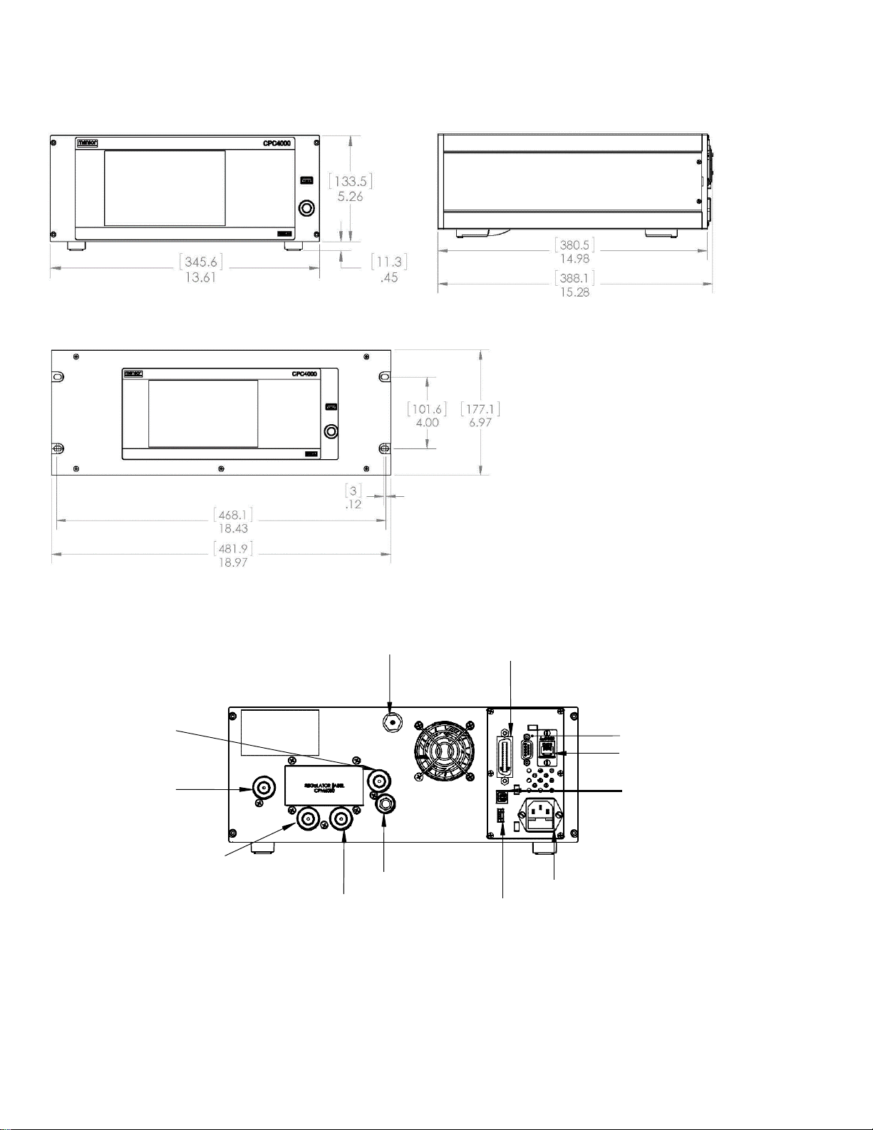
Reference Port
(7/16-20 UNF)
Baro Ref Port
(10-32 UNF)
IEEE-4888
RS-232
Ethernet Port
USB (device)
Power Supply
USB (host)
Vent (ATM)
Measure/ Control Port
(7/16-20 UNF)
Vent (ATM)
Supply Port
(7/16-20 UNF)
Exhaust Port
(7/16-20 UNF)
Dimensions in [mm]/ inch
Front view Side view
19” Rack Mount
Electrical and Pressure Connections – Rear
Page 7

WIKA-CAL Calibration Software
Easy and fast creation of a high-quality calibration
certificate
The WIKA-CAL calibration software is used for generating
calibration certificates or logger protocols for pressure
measuring instruments and is available as a demo version for a
cost-free download.
A template helps the user and guides him through the creation
process of a document.
In order to switch from the demo version to a full version of the
respective template, a USB key with the template has to be
purchased.
The pre-installed demo version automatically changes to the
selected full version when the USB key is inserted and is available as long as the USB key is connected to the computer.
■
Creation of calibration certificates for mechanical and
electronic pressure measuring instruments
■
Fully automatic calibration with pressure controllers
■
Calibration of relative pressure measuring instruments
with absolute pressure references and vice versa
■
A calibration assistant guides you through the calibration
■
Automatic generation of the calibration steps
■
Generation of 3.1 certificates per DIN EN 10204
■
Creation of logger protocols
■
User-friendly interface
■
Languages: German, English, Italian and more due with
software updates
For further information see data sheet CT 95.10
Calibration certificates can be created with the Cal-Template and logger protocols can be created with the Log-Template.
Cal Demo
Generation of calibration certificates limited to 2 measuring
points, with automatic initiation of pressures via a pressure
controller.
Cal Light
Generation of calibration certificates with no limitations on
measuring points, without automatic initiation of pressures via
a pressure controller.
Cal
Generation of calibration certificates with no limitations on
measuring points, with automatic initiation of pressures via a
pressure controller.
Log Demo
Creation of data logger test reports, limited to 5
measured values.
Log
Creation of data logger test reports without limiting
the measured values.
Page 8

06/2015
Scope of Delivery
■
Model CPC4000 industrial pressure controller (desktop case)
■
1.5 m / 5 ft power cord
■
Operating instructions
■
A2LA calibration certificate (standard on factory)
Options
■
DKD/DAkkS Calibration certificate
■
Barometric reference
■
Second reference pressure sensor
■
19" rack mounting kit
■
Customer-specific sy stem
■
Adapters & fittings for pressure connections
Accessories
■
Pressure adapters
■
Interface cable
■
Coalescing filter
■
Block & bleed valve
■
Pressure booster
■
WIKA-CAL calibration software
Ordering information
Model / Housing / Pressure range transducers / Pressure unit / Pressure type / Minimum pressure range / Maximum pressure
range / Accuracy / Type of calibration certificate / Barometric reference / Type of certificate for barometric reference / Digital
interface / Pressure port adapters / Power cord / Additional order details
© 2008 WIKA Alexander Wiegand SE & Co. KG, all rights reserved.
The specifications given in this document represent the state of engineering at the time of publishing. We
reserve the right to make modifications to the specifications and materials.
Page 8 of 8
Represented by:
Mensor
Email: sales@mensor.com
WIKA data sheet CT 27.40 ∙ 04/2015
201 Barnes Drive
San Marcos, Texas 78666 Toll
Free: 800-984-4200
Tel: 512-396-4200
Fax: 512-396-1820
 Loading...