

Page 1
Operating Instructions
High-Speed Pressure Controller
CPC3000
Operating Instructions - CPC3000 PN 0018043001 J • 02/2014
Page 2
High-Speed Pressure Controller
CPC3000
Operating Instructions - CPC3000
This Warning symbol indicates that danger of injury for persons and the
!
Warning
environment and/or considerable material damage (mortal danger, danger of
injury) will occur if the respective safety precautions are not taken.
!
Caution
i
Notice
This Caution symbol indicates danger for the system and material if the
respective safety precautions are not taken.
This Notice symbol does not indicate safety notices but information for a
better understanding of the facts.
2
Page 3

High-Speed Pressure Controller
CPC3000
Operating Instructions - CPC3000
Table of Contents
1. General information 7
1.1 Warranty 7
1.2 Important notice 7
1.3 FCC radio frequency emission notice 8
1.4 European radio frequency emission notice 8
1.5 Trademarks and copyrights 8
1.6 Software license agreement 8
1.7 Accreditations 9
1.8 Packaging for shipment 9
2. Safety notices 9
2.1 User responsibilities 9
2.2 General safety notices 10
2.3 Warnings and caution notices 10
3. Product description 13
3.1 Proper use 13
3.2 Features 14
3.3 Turning on the CPC3000 15
3.4 Front panel 15
3.5 Main menu 16
3.5.1 Keys, tabs, check boxes, labels/graphics 16
3.6 Front panel navigation and variations 17
3.6.1 Operating mode 17
3.7 Main menu setpoint entry options 19
4. Specifications 21
5. Installation 23
5.1 Introduction 23
5.2 Unpacking the system 23
5.3 Mounting (Rack mount kit option) 23
5.4 Installation 24
5.5 Rear panel 25
5.6 Pressure connections 25
5.7 Function of pressure connections 26
5.8 Electrical connections 27
5.8.1 Connecting the power supply and turning on the instrument 27
5.8.2 Connecting the communications interfaces 27
3
Page 4

High-Speed Pressure Controller
CPC3000
Operating Instructions - CPC3000
6. Starting operation 29
7. Local operation 31
7.1 Setting the operating language 31
7.2 Display configuration 31
7.3 Setpoint entry 33
7.4 Operating modes 36
7.5 Data entry 39
7.6 Pressure unit, pressure mode and emulation mode 39
7.7 Bar chart 40
7.8 Setup menus 40
7.8.1 Setup display 41
7.8.2 Setup control 42
7.8.3 Setup remote 43
7.8.4 Setup info 44
7.8.5 Setup service 45
7.8.5.1 Zero (non-password protected) 45
7.8.5.2 Unlock setup for calibration and regulator adjustment 46
7.8.5.3 Change Password 47
7.8.5.4 Calibrate sensor or optional barometer 48
7.8.5.4.1 Calibration data 49
7.8.5.4.2 Edit calibration 50
7.8.5.4.3 Live calibration 51
8. Remote Operation 52
8.1 Remote setup 52
8.2 Remote setup - Ethernet 52
8.3 Remote setup - USB 53
8.4 Remote setup - IEEE-488 53
8.5 Remote command set 54
8.5.1 Mensor command set 54
8.5.2 PCS 400 commands emulated 61
8.5.3 PCS 200 commands emulated 63
8.5.4 DPI 510 commands emulated 64
8.5.5 IEEE 488.2 commands 65
8.5.6 SCPI commands 66
8.5.7 Output Formats 68
9. Trouble-shooting measures 69
4
Page 5

High-Speed Pressure Controller
CPC3000
Operating Instructions - CPC3000
9.1 Table: fault description and measures 69
10. Re-calibrating and servicing 71
11. Removal of the system 72
12. Transport of the system 73
13. Storage of the system 74
14. Placing out of service 75
15. Appendix 76
Sales and service international 77
Measurement units 81
Conversion factors, pascal 82
5
Page 6

High-Speed Pressure Controller
CPC3000
Operating Instructions - CPC3000
NOTES
6
Page 7

High-Speed Pressure Controller
CPC3000
Operating Instructions - CPC3000
1. General information
1.1 Warranty
All products manufactured by Mensor are warranted to be free of defects in workmanship and
materials for a period of one year from the date of shipment. No other express warranty is given,
and no affirmation of Seller, by words or actions, shall constitute a warranty. SELLER DISCLAIMS
ANY IMPLIED WARRANTIES OF MERCHANTABILITY OR FITNESS FOR ANY PARTICULAR
PURPOSES WHATSOEVER. If any defect in workmanship or material should develop under conditions of normal use and service within the warranty period, repairs will be made at no charge to
the original purchaser, upon delivery of the product(s) to the factory, shipping charges prepaid.
If inspection by Mensor or its authorized representative reveals that the product was damaged
by accident, alteration, misuse, abuse, faulty installation or other causes beyond the control
of Mensor, this warranty does not apply. The judgment of Mensor will be final as to all matters
concerning condition of the product, the cause and nature of a defect, and the necessity or
manner of repair. Service, repairs or disassembly of the product in any manner, performed without
specific factory permission, voids this warranty.
MENSOR MAKES NO WARRANTY OF ANY KIND WITH REGARD TO THIS MANUAL, INCLUDING,
BUT NOT LIMITED TO, THE IMPLIED WARRANTIES OF MERCHANTABILITY AND FITNESS FOR
A PARTICULAR PURPOSE. Mensor shall not be liable for errors contained herein or for incidental
or consequential damages in connection with the furnishing, performance, or use of this material.
1.2 Important notice
Since product improvement is a continuous process at Mensor, we reserve the right to change
specifications and other information contained in this manual without notice.
Mensor has made a concerted effort to provide complete and current information for the proper
use of the equipment. If there are questions regarding this manual or the proper use of the equipment, contact either Mensor or WIKA:
Mensor
201 Barnes Drive
San Marcos, Tx 78666
TEL: 1.512.396.4200
1.800.984.4200 (USA only)
WEB SITE: www.mensor.com
FAX: 1.512.396.1820
E-MAIL: sales@mensor.com
tech.support@mensor.com
quality@mensor.com
WIKA Alexander Wiegand SE & Co. KG
Alexander-Wiegand-Straße 30
D-63911 Klingenberg / Germany
TEL: (+49) 93 72/132-9986
WEB SITE: www.wika.de
FAX: (+49) 93 72/132-8767
E-MAIL: testequip@wika.de
7
Page 8
High-Speed Pressure Controller
CPC3000
Operating Instructions - CPC3000
1.3 FCC radio frequency emission notice
This equipment has been tested and found to comply with the limits for a
Class A digital device, pursuant to Part 15 of the FCC Rules. These limits are
!
Warning
1.4 European radio frequency emission notice
!
Warning
designed to provide reasonable protection against harmful interference when
the equipment is operated in a commercial environment. This equipment
generates, uses, and can radiate radio frequency energy and, if not installed
and used in accordance with the instruction manual, may cause harmful
interference to radio communications. Operation of this equipment in a
residential area is likely to cause harmful interference in which case the user
will be required to correct the interference at his or her own expense.
Use shielded cables to connect external devices to this instrument to minimize
RF radiation.
EN 55022 (or CISPR 22)
WARNING! This is a class A emission device. This equipment may cause radio
interferences in residential environments. The operator may be required to
make appropriate corrective measures.
EN 55011 (or CISPR 11)
WARNING! This is a class A emission device intended for operation in an
!
Warning
1.5 Trademarks and copyrights
WIKA is a registered trademark of WIKA Alexander Wiegand SE & Co. KG. Mensor is a registered
trademark of Mensor.
© 2006, Mensor. All rights reserved.
i
Notice
1.6 Software license agreement
This product contains intellectual property, i.e., software programs, that are licensed for use by the
end user/customer (hereinafter “end user”).
This is not a sale of such intellectual property.
industrial environment. It can cause interference under certain circumstances
if operated in other environments e.g. residential or commercial areas. The
operator may have to take appropriate corrective measures.
All other brand and product names are trademarks or registered trademarks
of their respective companies.
The end user shall not copy, disassemble or reverse compile the software program.
8
Page 9

High-Speed Pressure Controller
CPC3000
Operating Instructions - CPC3000
The software programs are provided to the end user “as is” without warranty
i
Notice
WIKA, Mensor and its suppliers shall not be held to any liability for any damages suffered or
incurred by the end user (including, but not limited to, general, special, consequential or incidental
damages including damages for loss of business profits, business interruption, loss of business
information and the like), arising from or in connection with the delivery, use or performance of the
software program.
1.7 Accreditations
Mensor is registered to ISO 9001:2008. The calibration program at mensor is accredited by A2LA,
as complying with both the ISO/IEC 17025:2005 and the ANSI/NCSL Z540-1-1994 standards. All
Mensor primary standards are traceable to NIST.
1.8 Packaging for shipment
If the product must be shipped to a different location or returned to Mensor for any reason through
a common carrier it must be packaged properly to minimize the risk of damage.
of any kind, either expressed or implied, including, but not limited to, warranties of merchantability and fitness for a particular purpose. The entire risk of
the quality and performance of the software program is with the end user.
The recommended method of packing is to place the instrument in a container, surrounded on all
sides with at least four inches of shock attenuation material such as styrofoam peanuts.
2. Safety notices
2.1 User responsibilities
To ensure safety, the user must make sure that:
The system is used properly (refer to "3.1 Proper use" in the section "Product description"), no
dangerous media are used and that all technical specifications are observed.
Safety mechanisms exist, which exclude any danger to persons or machinery through improper
pressurization.
The system is operated in perfect operating condition.
This operation manual is legible and accessible to the user at the system's location.
The system is operated, serviced and repaired only by staff who are authorized and qualified to
do so.
The operator receives instruction on industrial safety and environmental protection, and is
knowledgeable of the operating instructions and the safety notices contained therein.
The power cord is the disconnection device. Its outlet should be accessible and contain a
protected earth ground.
9
Page 10

High-Speed Pressure Controller
CPC3000
Operating Instructions - CPC3000
2.2 General safety notices
The system should only be operated by trained personnel who are familiar
with this manual and the operation of the instrument.
!
Caution
!
Warning
A condition for trouble-free and safe operation of this system is proper
transport, proper storage, installation, assembly and proper use as well as
careful operation and maintenance.
Any operation not described in the following instructions should be prohibited.
The system must be handled with the care required for an electronic precision
instrument (protect from humidity, impacts, strong magnetic fields, static
electricity and extreme temperatures). Do not insert any objects into the
instrument.
The system is powered via the power cable with a voltage that can cause
physical injury. Even after disconnecting the system from the power supply,
dangerous voltages can temporarily occur due to capacitance.
Although the contacts of the integrated relays located at the back of the
instrument are only approved for small electric currents, dangerous voltages
or currents can occur in the case of faults or failures.
Extreme care must be taken with pressure connections when using hazardous
or toxic media.
Repairs must only be performed by authorized service personnel.
Additional safety notices are found throughout this manual.
2.3 Warnings and caution notices
HIGH PRESSURE! High pressure gases are potentially hazardous. Energy
!
Warning
!
Warning
!
stored in these gases can be released suddenly and with extreme force. High
pressure systems should be assembled and operated only by personnel who
have been trained in proper safety practices.
POSSIBLE INJURY! The tubing, valves and other apparatus attached to the
controller must be adequate for the maximum pressure which will be applied,
otherwise physical injury to the operator or bystander is possible.
Caution: use the proper pressure medium. Use only clean, dry non-corrosive
gases. This instrument is not designed for oxygen use.
Caution
10
Page 11
High-Speed Pressure Controller
CPC3000
Operating Instructions - CPC3000
!
Warning
!
Warning
The user must use caution when controlling from a very high pressure down
to a very low pressure when a vacuum pump is connected to the exhaust port.
Large volumes of gas may be present in the device under test and will exhaust
through the Exhaust/Vacuum port in excess of the capacity of the internal relief
valve, possibly causing damage to the vacuum pump.
HIGH SOUND LEVELS! Pressures from 600 psig and up can generate sound
levels above 100 db for brief periods when they are exhausted directly to
atmosphere. If no muffling devices are attached to the exhaust or vent port,
then ear protection is advised for personnel in the vicinity of the instruments
that will be operated under such conditions.
!
Warning
!
Caution
!
Warning
!
Warning
NOT EXPLOSION PROOF! Installation of this instrument in an area requiring
devices rated as intrinsically safe is not recommended.
Caution: ESD protection required. The proper use of grounded work surfaces
and personal wrist straps are required when coming into contact with exposed
circuits (printed circuit boards) to prevent static discharge damage to sensitive
electronic components.
Before the system is switched on, the user must verify that the system was
installed correctly and that all connections meet current regulations.
The user must ensure that all specifications such as supply voltage, operating
temperature, humidity, sensor-specific pressure media and pressure ranges
are observed.
Before pressurizing, the user must ensure through appropriate protective
measures that the system or the device will not be overpressurized. When
working with or on an instrument, safety glasses should be worn.
In areas where the system is operated there must be sufficient air ventilation
!
Warning
!
Warning
due to inert gases that will escape during use.
High pressure can accelerate parts in a manner that could be hazardous and
cause physical injury.
Additional warning and caution notes are included throughout this manual.
11
Page 12

High-Speed Pressure Controller
CPC3000
Operating Instructions - CPC3000
NOTES:
12
Page 13
High-Speed Pressure Controller
CPC3000
Operating Instructions - CPC3000
3. Product description
3.1 Proper use
The CPC3000 High Speed Pressure Controller is a bench top or rack mounted Digital Pressure
Calibrator/Controller used for test and calibration of mechanical pressure gauges, pressure
switches, sensors, transducers, transmitters and any pressure related devices where time to
set point is the most critical requirement.
Only dry clean air or nitrogen should be used as the pressure medium. Shop
air should be avoided and corrosive, oxidizing, condensing, explosive gases
!
Warning
!
Warning
should be strictly avoided.
The maximum permissible supply pressure at the supply port should be
10% over full scale value of the sensor installed.
Very fast pressure changes can damage the sensor, due to mechanical
stress on the sensor; especially if the fast pressure change leads to an
internal pressure which is higher then the full scale of the internal sensor
(even if it is only for a fraction of a second). In some cases, the internal relief
valves cannot react quickly enough to protect the sensor.
!
Warning
The Internal pressure sensors have a calibration certificate for the entire measuring chain.
The system is not suitable for use in areas with an explosion hazard.
If the CPC3000 is not used according to this manual, safe operation of the
system is not guaranteed.
The user of the system and not the manufacturer is responsible for all
physical and material damage resulting from improper use!
13
Page 14
High-Speed Pressure Controller
CPC3000
Operating Instructions - CPC3000
3.2 Features
Below is a short list of significant features designed into the CPC3000:
1. The CPC3000 will control (up scale or down
scale) into a 150 ml volume, to within 0.025%
of the set point, in 3 seconds or less.
2. Uncertainty of 0.025% FS or optional 0.025%
IS-50, 365 day calibration interval.
3. Lightweight compact case with handle.
4. Manual operation via the color touch screen
and easy access to auxiliary screens allow
quick changes to the set point using the
"step" and "jog" screens.
5. Remote operation over IEEE-488, USB, or
Ethernet.
6. Emulation of other qualified controllers.
7. An optional internal high accuracy baromet
ric reference sensor for emulation of gauge
pr
essure and absolute pressure.
8. A large color LCD display with a touch screen
for intuitive operator interface.
9. Multiple languages.
-
14
Page 15
High-Speed Pressure Controller
CPC3000
Operating Instructions - CPC3000
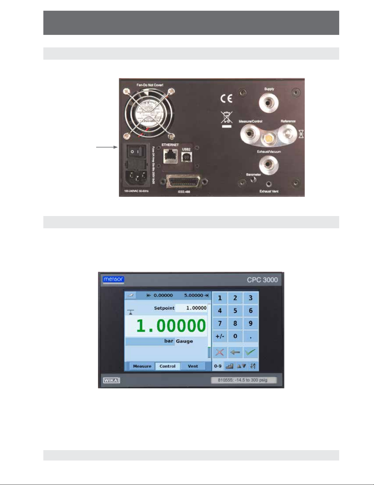
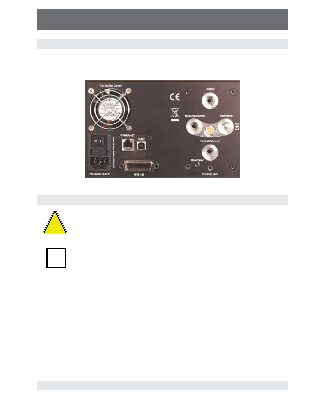
3.3 Turning on the CPC3000
The power switch is located on the rear of the instrument as shown in Figure - "Rear Panel".
Power Switch
Figure - Rear Panel
3.4 Front panel
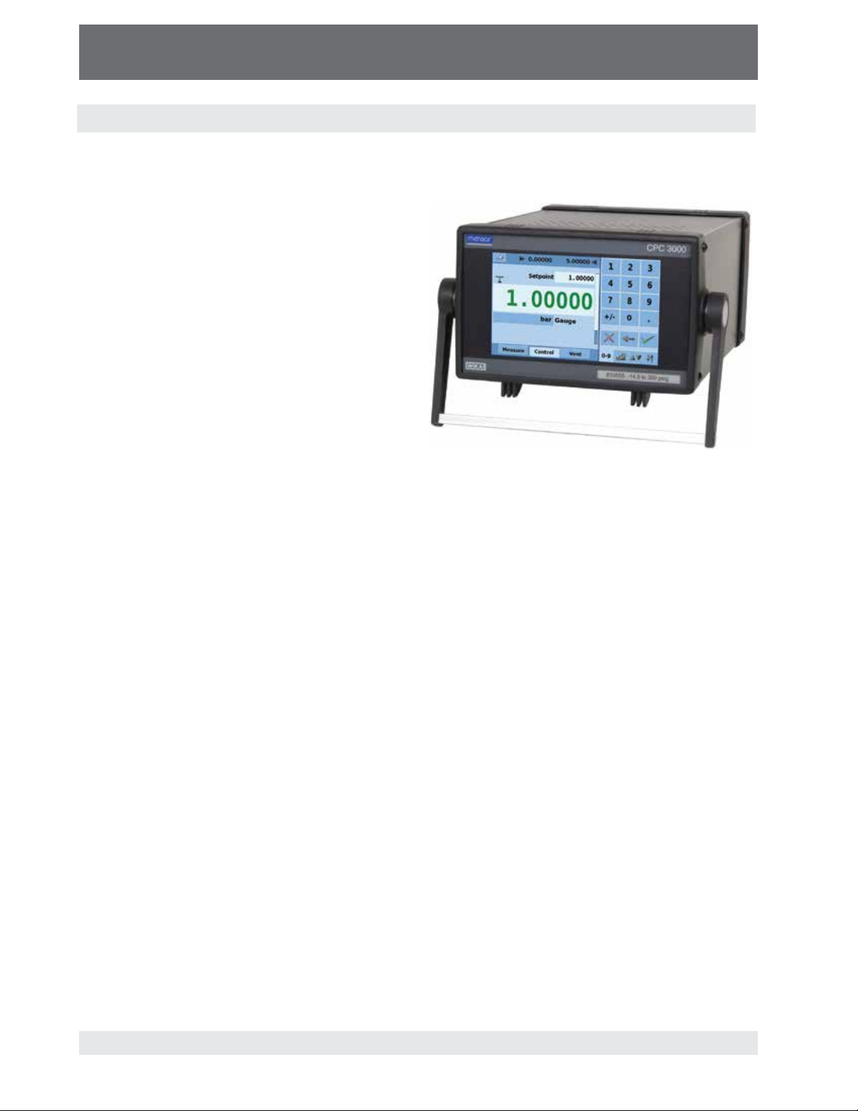
The CPC3000 front panel, shown in Figure - "Front Panel", includes a 7 inch color display featuring
touch screen technology. Operator input is accomplished by pressing the number, words or symbols
presented on the display. There are no mechanical keypads or switches on the front panel.
Figure - Front Panel
15
Page 16
High-Speed Pressure Controller
CPC3000
Operating Instructions - CPC3000
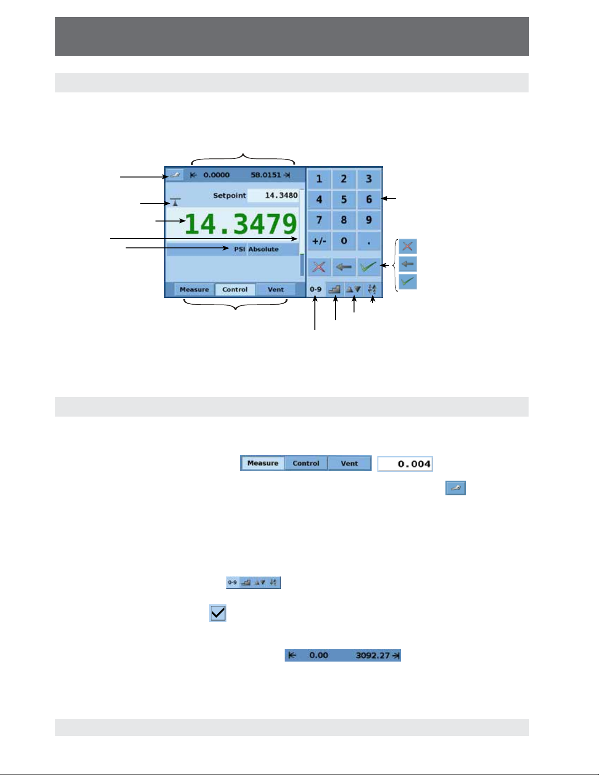
3.5 Main menu
When the CPC3000 is powered up it takes about 40 seconds for initialization, then displays a
screen similar to the Figure - "Initial Screen" below.
User defined control range limits
(configurable via SETUP-CONTROL)
SETUP menu
Stability indication
Current pressure value
Bar graph
Pressure Units
and Mode
Operating Mode
Jog key pad selection tab
User defined jog key pad selection tab
Step key pad selection tab
Numeric key pad selection tab
Numeric keypad
Delete selected set point
Delete last entered digit
Accept selected set point
Figure - Initial Screen
3.5.1 Keys, tabs, check boxes, labels/graphics
Keys: There are two types of keys: those that act as a switch to change a condition and
those that open a data entry screen when pressed. Keys have borders with a three dimensional, shadowed effect (examples:
, ). Throughout this
manual keys are represented with the displayed characters enclosed in brackets ( Example:
[MEASURE] ) or a description and the actual graphic icon (example: [SETUP]
). Pressing a key will have one of the following results: 1) instant, single step response, 2) continuously repeating steps while the key is held down, 3) the key will change colors indicating that
the associated function is active or 4) a data entry dialog box will open. Operators will quickly
become accustomed to the particular characteristics of the frequently used keys.
Tabs: Tabs are analogous to tabs in a notebook that allow switching quickly between related
screens. Tabs are keys that allow the operator to switch between a group of screens that have a
similar purpose, for example the
tabs allow the operator to quickly switch between
four screens used to enter the setpoint.
Check Boxes: Check Boxes
allow for the inclusion or exclusion of specific elements or
conditions.
Labels and Graphics: Labels and Graphics are text, or graphics that display information, but
do not respond to being touched (examples:
). They indicate choices
that have been made in the setup menus or indicate existing conditions as pressure is controlled or
measured.
16
Page 17
High-Speed Pressure Controller
CPC3000
Operating Instructions - CPC3000
3.6 Front panel navigation and variations
Screen Hierarchy: Navigation within the CPC3000 is similar to a computer file system or a web
page. Keys or tabs activate sub-menus. Within the sub-menus there may be related sub-menus
or selections. To return back through the hierarchy of screens the [BACK]
Throughout this manual screen hierarchy will be designated using the following convention:
"main->sub-menu->selection" or "main->sub-menu->tab->selection". Sometimes, a reference
to a key will be made in the context of a specific screen by simply giving the key name in bold
square brackets [KEY NAME] or by using the key name along with the actual graphic icon. The
Hierarchical menu structure is very intuitive and will become more obvious after reviewing following examples.
Bar Graph: The bar graph shows the relative indication of the range of the internal sensor, the user
defined limits on the internal sensor, the unused portion of the internal pressure sensor range, the
setpoint and the magnitude of the actual controlled pressure. The user defined control limits can
be selected in the Main->Setup->Control screen and can be set to correspond to the range of
the device under test. It is important to note that when the STEP keypad is active in percent
mode, each step is a percent of the user defined limit not the full scale of the internal sensor.
This is useful when calibrating or testing various range devices. Figure - "Bar Graph" shows the
bar graph when the CPC3000 is in vent mode with a setpoint of 2.5 psig. The user defined range is
0 to 4 and there is an unused portion of the internal sensor.
Figure - Bar Graph
Bar graph shows relative indication of:
key is provided.
• Range of the Internal sensor
• User defined limits
• Unused portion of the internal
sensor range
• Setpoint
• Current pressure reading
3.6.1 Operating mode (press
MEASURE
In MEASURE mode, the instrument measures the pressure connected to the measure port (on
changing from CONTROL mode: the last controlled pressure will be held/sealed in the connected test assembly).
CONTROL
In CONTROL mode the instrument provides a very precise pressure at the measure port.
VENT
VENT opens measure port to atmospheric pressure.
to select mode):
17
Page 18
High-Speed Pressure Controller
CPC3000
Operating Instructions - CPC3000
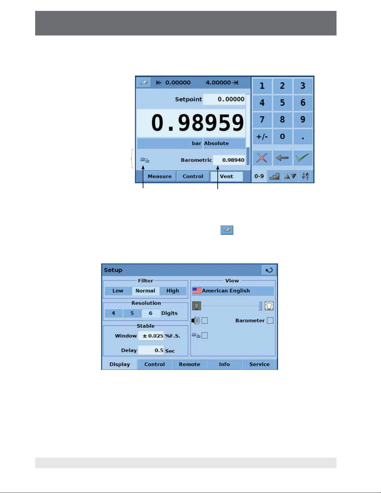
Optional elements can be chosen in the Main->Setup->Display screen explained in section
7.8.1 of this manual. Each optional element is displayed in the area below the pressure units.
Area for optional elements
Communication status
Optional barometric
reference display
Figure - Optional Display elements
Navigation to the SETUP screens is achieved pressing the
Icon. Setup Figure - "Main Setup
Screen" shows the setup screen with the display tab activated. Other tabs at the bottom are used
to navigate to additional setup screens. Setup screens will be discussed in detail in section 7.8 of
this manual.
18
Figure - Main Setup Screen
Page 19
High-Speed Pressure Controller
CPC3000
Operating Instructions - CPC3000
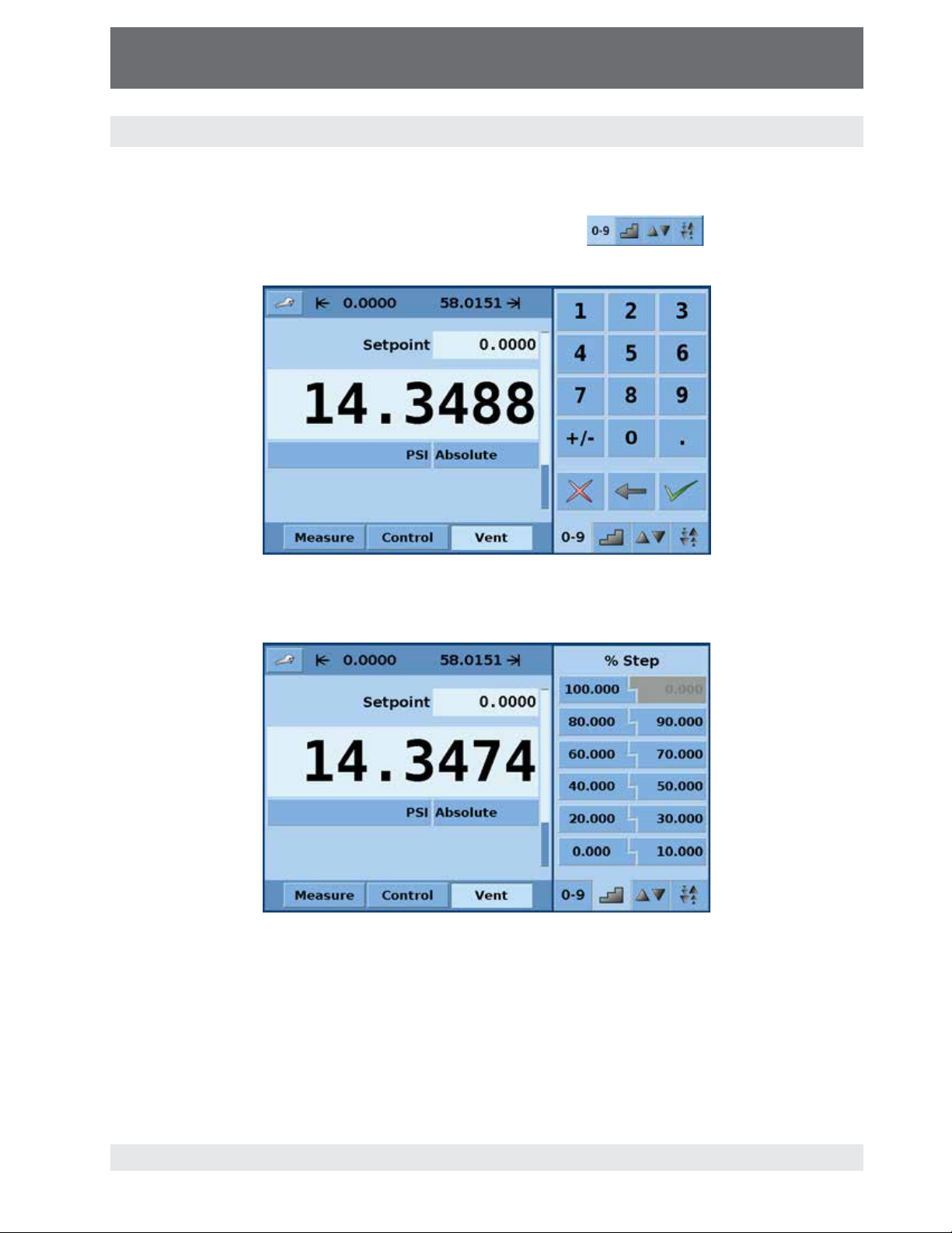
3.7 Main menu setpoint entry options
There are four different ways to enter the setpoint in the CPC3000. Each setpoint entry method is
explained in detail in section 7.3 Setpoint Entry.
Pressure setpoint entry options are chosen using the tab keys
will open the respective screen for setpoint entry.
Figure - Numeric Keypad
Figure - "Numeric Keypad" shows the main menu with the numeric keypad selected.
. Pressing each tab
Figure - "Step Keypad" shows the main menu with the step keypad selected.
Figure - Step Keypad
19
Page 20
High-Speed Pressure Controller
CPC3000
Operating Instructions - CPC3000
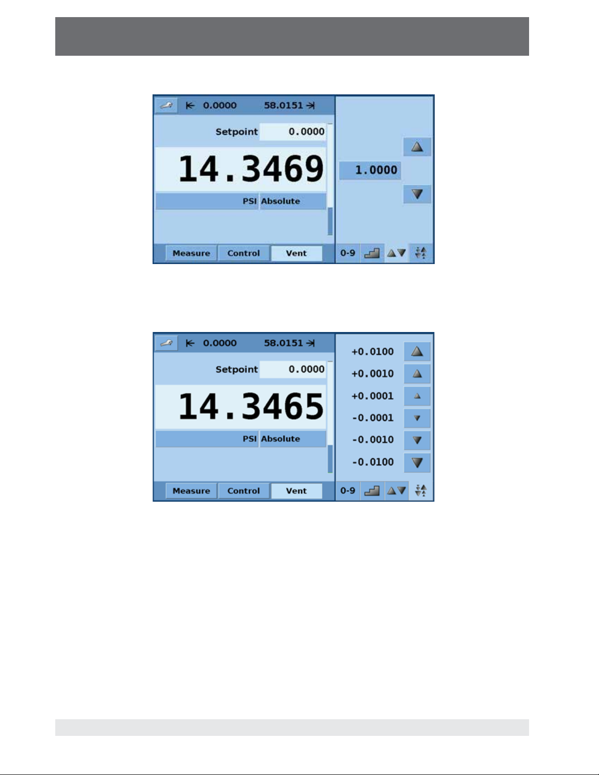
Figure - "User Defined Jog Keypad" shows the main menu with the user defined jog keypad
selected
Figure - User Defined Jog Keypad
Figure - Jog Keypad
Figure - "Jog Keypad" shows the main menu with the jog keypad selected.
20
Page 21

High-Speed Pressure Controller
CPC3000
Operating Instructions - CPC3000
4. Specifications
Specifications
Pressure ranges, standard psi Gauge: 0 ... 5 up to 0 ... 1500 psig (0 ... 0.35 to 0 ... 100 bar)
Pressure types
Uncertainty
Definitions pertaining to
uncertainty
Unit CPC3000
Absolute: 0 ... 14.5 to 0 ... 1515 psia (0 ... 1 to 0 ... 101 bar)
Bi-directional: 5 ≤ span ≤ 1515
Absolute, gauge, and bi-directional ranges
0.025% full span for all standard pressure ranges specified above..
Max = the maximum value of a range, also known as the full scale value.
Example, for a range of –15 ... 145, Max = 145.
Min = the minimum value of a range.
Example, for a range of –15 ... 145, Min = –15
Full Span (FS) = Max – Min.
Example, for 0 ... 145 the Full Span is 145, for –15 ... 145 the Full Span is 160
Reading = the value of the sensor output
IS = IntelliScale is a combination of %Max range and %Reading
Total Uncertainty (k=2) includes hysteresis, linearity, repeatability, reference
standard, drift and temperature effects over the calibrated range for the calibration interval specified, with periodic re-zeroing.
Optional IntelliScale uncertainty
Transducer Range (psig) Total Uncertainty
0 ... 14.5 to 0 ... 1500 0.025% IS-50
Transducer Range (psia) Total Uncertainty
0 ... 14.5 to 0 ... 1515 0.025% IS-50
Transducer Range (psi) Total Uncertainty
-15 ... 145 to -15 ... 1500 0.025% IS-50
5 ≤ span < 145 0.025% of Full Span (365 days)
(1) 0.025% IntelliScale-50 (0.025% IS-50): Uncertainty from Min to 50% of Max
= (0.025% x 50% x Max) or 0.025% of Reading from 50% to 100% of Max.
Optional barometer
Optional barometer uncertainty
Uncertainty in emulation mode
Compensated temperature range
Calibration Interval
Pressure units: English psi,psf,osi,tsi,tsf,atm,inHg0˚C,inHg60˚F,mtorr,torr,inSW,ftSW,inH
Pressure units: Metric mbar, bar, gm/cm
Pressure units user defined
Slew rate 3 seconds to stable flag (+/-0.025% full scale pressure) for a 10% pressure
Overshoot
Pressure ports 7/16-20 Female SAE threaded ports for Measure/Control, Exhaust, Reference,
°C 15 ... 45
days 365
% FS <1 in high speed mode
8 ... 17 psia (0.55 ... 1.17 bar)
0.02% R from 8.5 to 17 psia for 365 days.
RSS of the uncertainty of the pressure sensor and the uncertainty of the barometer.
inH2O20˚C,inH2O60˚F,ftH2O4˚C,ftH2O20˚C,ftH2O60˚F
mmHg0˚C,cmHg0˚C,mHg0˚C,mSW,mmH2O4˚C,cmH2O4˚C,mH2O4˚C,
mmH2O20˚C,cmH2O20˚C,mH2O20˚C
2 (multiplier from psi or Pascal)
change typical into 150cc volume at pressures greater than 5 PSI. Larger
volumes can lengthen this time. Controlling to pressures less than atmosphere
can lengthen this time.
4 seconds to stable flag for pressure ranges >70 bar or 1000 psi.
and Supply. Barometric Reference port is a hose barb.
2
, kg/cm2, kg/m2, Dy/cm2, pascal, hPa, kPa, MPa,
Gauge
Absolute
Bi-directional
(1)
(cal interval)
(1)
(365 days)
(1)
(cal interval)
(1)
(365 days)
(1)
(cal interval)
(1)
(365 days)
O4˚C,
2
21
Page 22

High-Speed Pressure Controller
CPC3000
Operating Instructions - CPC3000
Filter elements 40 micron filter element included in each pressure port (excluding the optional
Permissible pressure media
Parts exposed to pressure media 6000 series aluminum, 316 SS, brass, Teflon, Urethane, Silicone, RTV, Silicone
Overpressure protection
Instrument mounting
Display
Resolution
Warm-up time
Digital Interface
Power Supply
Maximum pressure - supply port
Pneumatic overpressure protection
Operating temperature
Storage temperature
Air humidity
Operating position
Weight
Dimensions
CE-mark
Calibration
digits Six significant digits
min approx. 15
% FS 110 … 120
°C 0 … 50
°C 0 ... 70
% 0 … 95 (relative humidity without moisture condensation)
lbs. (kg) <20 (<9.1) with all internal options
in.(mm) 5¼ x 8⅜ x 12 (133 x 213 x 305). See "Figure - Dimensions" shown below.
barometer and the reference port on a gauge sensor)
Clean, dry, non-corrosive gases
grease, PVC, Epoxy, Ceramics
Pressure relief valves
Desk top with bezel and handle, or optional rack mount kit.
7.0" color LCD
IEEE-488, Ethernet, USB
100- 240 VAC, 50/60 Hz, 700 mA max
internal relief valves
Negligible, can be removed with re-zeroing
Conformity certificate
NIST traceable calibration certificate included, A2LA certification standard.
Front view Side view
10.1875
8.6875
Rear view
12.3125
5.5
7.375
22
Figure - Dimensions
(shown in inches)
Page 23
High-Speed Pressure Controller
CPC3000
Operating Instructions - CPC3000
5. Installation
5.1 Introduction
The initial installation of the CPC3000 includes the following steps: Unpack the system, place it in
a suitable workspace, connect it, switch it on and configure.
5.2 Unpacking the system
Unpack all components of the CPC3000 carefully and check for damage. Report any damage to
the carrier immediately.
Apart from any additional components ordered, a shipment consists of:
CPC3000 controller
Pressure adapter fittings
Power cable
Manual
Calibration certificate
Optional: Rack mount kit or any other accessories ordered
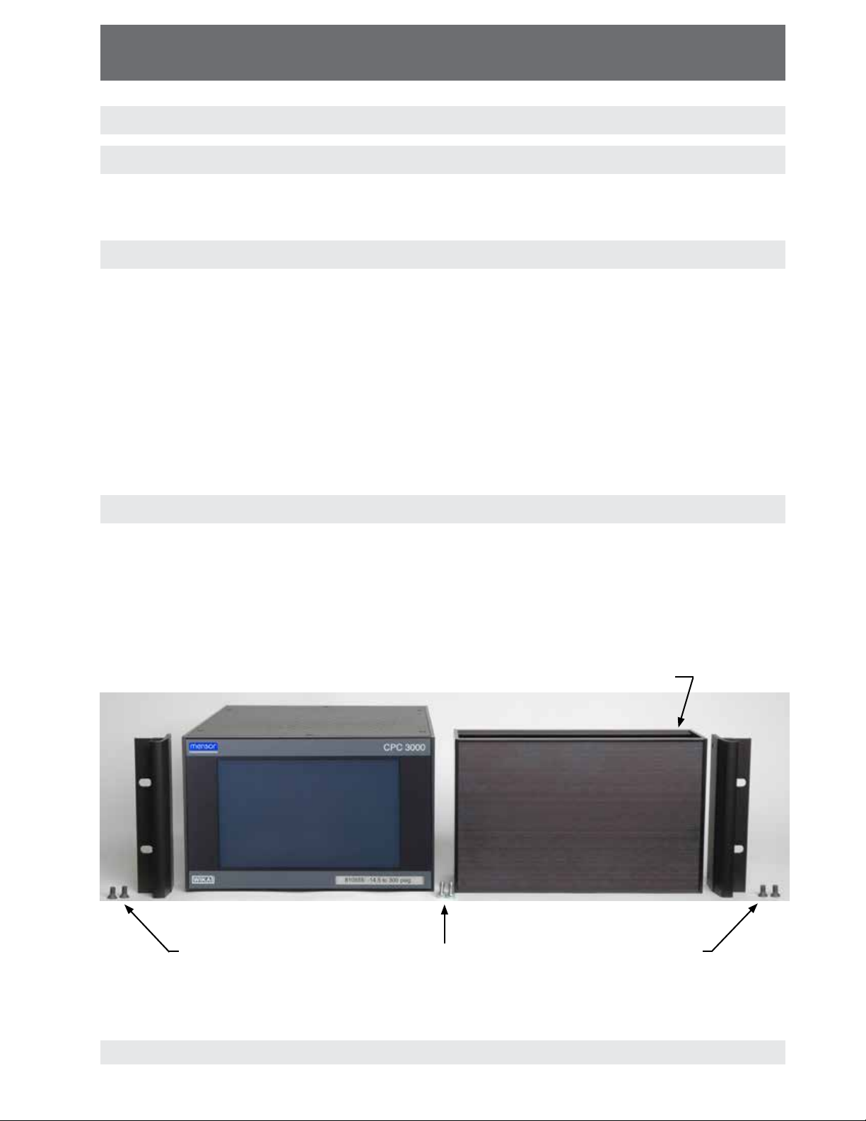
5.3 Mounting (Rack mount kit option)
Your new instrument can be set up on a table top or it can be rack-mounted. Rack mount adapters are optional on the CPC3000.
A rack mount kit (part number 0018055001) allows the customer to install a CPC3000 into a standard 19" instrument rack. The kit includes rack mount angles as well as rack mount adapter panels
and hardware to mount the instrument.
(8) 6-32x3/8" screws
(2) 10-32x3/8"
screws
(2) 10-32x3/8"
coupling screws
(2) 10-32x3/8"
screws
Figure - Rack mount kit
23
Page 24

High-Speed Pressure Controller
CPC3000
Operating Instructions - CPC3000
5.4 Installation
The installation site must meet the following conditions:
Operating Temperature: 0 to 50°C
Humidity: 0 to 95 % relative humidity non-condensation
Flat, horizontal location; secure fixed working surface (desk top model) or installation in a 19"
rack mount.
At the back of the instrument sufficient air circulation must be provided to avoid an
accumulation of the heat conducted to the outside by the fan.
During operation, pressure escapes through the vent port in the back of the instrument.
Personnel should not have access to the rear vent and exhaust port during operation.
The power cord is the disconnection device. Its outlet should be accessible and contain a
protected earth ground.
Avoid the following influences:
Direct sunlight or proximity to hot objects
Unstable installation position
Mechanical vibration
Proximity to sources of strong electromagnetic fields, such as high tension appliances, mobile
telephones or mains
Soot, steam, dust and corrosive gases
Environment with explosion hazard, flammable atmospheres
Pressure supply requirements:
Stable supply pressure 10% higher than the full scale of the internal transducer
Permissible media: dry, clean air or nitrogen
Vacuum: minimum 50 litres/min (if required)
An angle of inclination of the system of more than 3 degrees can cause a deviation
in the measured pressure and should be avoided. Zeroing the unit at the angle of
inclination will nullify this deviation.
Applying supply pressure higher than the recommended pressure can cause
!
Warning
permanent damage to the controller!
24
Page 25
High-Speed Pressure Controller
CPC3000
Operating Instructions - CPC3000
5.5 Rear panel
Five pneumatic pressure ports are located on the rear panel (see labels shown in Figure -"Rear
panel"). Positioned on the left are the the off/on switch, the line fuses, a protective grill covering
the ventilating fan, Ethernet, USB and IEEE-488 connector.
Figure - Rear Panel
5.6 Pressure connections
The pressure connections must be installed according to the following
instructions, observing the relevant regulations. The installation should be
!
Warning
i
Notice
All of the pressure ports on the rear are female 7/16 - 20 SAE/MS straight threads per MS16142
and SAE J514 table 14. They require a tube fitting boss seal with an o-ring per MS33656. Mensor
provides female pressure adapter fittings with the instrument. The pressure connections can be
made to these adapters with the proper mating hardware. Do not use sealant on fittings sealed
with an o-ring.
performed by persons familiar with, and who can work according to, the
safety regulations for working on pneumatic/hydraulic systems.
When making up a connection to an o-ring adapter port use a back-up wrench to
prevent over-stressing the threads in the manifold block.
25
Page 26
High-Speed Pressure Controller
CPC3000
Operating Instructions - CPC3000
5.7 Function of pressure connections
MEASURE/CONTROL port
Below the label "MEASURE/CONTROL" is a pressure port. In MEASURE mode this port
connects a pressure, applied externally or previously generated by the controller, to the
internal sensor where the pressure is measured (within the range of the internal sensor). In
CONTROL mode this port supplies an output pressure controlled by the internal regulator at the
commanded setpoint.
SUPPLY port
Below the label "SUPPLY" is a pressure port. This port should be supplied with a pressure that
is between 110% and 120% of the full scale pressure of the internal sensor. In other words,
10% to 20% above the full scale pressure of the internal sensor
supply port”) in the specifications section and pressure media requirements.)
EXHAUST/VACUUM port
Below the label "EXHAUST/VACUUM" is a pressure port. If a sub-atmospheric control pressure
is required a vacuum pump must be connected to this port. Otherwise, this port may be left
open to atmosphere.
The user must use caution when controlling from a very high pressure down
to a very low pressure when a vacuum pump is connected to the exhaust port.
!
Warning
Large volumes of gas may be present in the device under test and will exhaust
through the Exhaust/Vacuum port in excess of the capacity of the internal
relief valve, possibly causing damage to the vacuum pump.
(see “Maximum pressure -
VENT outlet
Between the MEASURE/CONTROL port and the REFERENCE port is the pressure outlet. In
VENT mode the pressure within the system is released through this outlet.
HIGH SOUND LEVELS! Pressures from 600 psig and up can generate sound
levels above 100 db for brief periods when they are exhausted directly to
!
Warning
REFERENCE port
On gauge units this port is connected to the reference side of the transducer, and on absolute
units it is internally capped. This port is normally left open to atmosphere but may be attached
to a snubber assembly on very low pressure instruments.
!
Warning
atmosphere. If no muffling devices are attached to the exhaust or vent port,
then ear protection is advised for personnel in the vicinity of the instruments
that will be operated under such conditions.
The controller must be protected from overpressure.
Pipes, couplings and other components used for connecting the supply,
exhaust/vacuum and the measure/control port must be suitable for the appli-
cation and rated for the applied pressures.
The user must ensure that the pressure media is clean and dry. If necessary,
the internal sensors and mechanisms must be protected by using a liquid trap
or coalescing filter.
26
Page 27

High-Speed Pressure Controller
CPC3000
Operating Instructions - CPC3000
5.8 Electrical connections
The electrical installation has to be performed according to the following
instructions while observing the relevant regulations. It is to be carried out by
!
Warning
5.8.1 Connecting the power supply and turning on the instrument
a qualified electrician.
Before connecting the power supply, make sure that the supply voltage agrees
with the specification of the power unit. Switch off the system before connecting the power via the power switch at the rear of the instrument.
!
Warning
The power input socket is to be connected according to the regulations with the country-specific
connection cable supplied to a power supply that lies within the required specification. To power-
on the instrument switch the power switch ON (located on the rear of the instrument; also see
section 6, Starting operation).
5.8.2 Connecting the Communications interfaces
USB 2.0 FS Interface
The USB 2.0 FS connection on the rear panel of the CPC3000 is a USB-B Type connector. The
USB driver can be downloaded at http://www.mensor.com/download_software_instrument_en_
um.WIKA.
IEEE-488 Interface (GPIB)
The connection of the IEEE-488 interface is designed as a 24-pin IEEE-488-socket.
The manufacturer of the host IEEE-488 interface board provides software to allow communication
between the board and various programming languages.
An interactive program for debugging is usually provided as well. Refer to the board manufactur-
er’s documentation for more information.
Only the power cable supplied should be used.
The 3-pin power cable supplied is fitted with a ground lead. Operate the
system only from a 3-pin socket, making sure that the ground lead is properly
connected.
27
Page 28

High-Speed Pressure Controller
CPC3000
Operating Instructions - CPC3000
ETHERNET Interface
The ethernet communication port allows the CPC3000 to communicate with computers using
10/100 Based-T specifications.
Please consult your Computer Resources Department prior to connecting
!
Warning
Ethernet communications are transmitted over a standard RJ-45 cable. Connecting directly to
a PC requires a crossover Ethernet cable. Hub or router connections require a straight Ethernet
cable.
Prior to first time use of ethernet communication, the four parameters, IP, Netmask, Gateway, and
Port must be setup. These are configured in the communications setup screen.
this instrument to your network to verify there are no conflicts with existing IP
addresses.
28
Page 29

High-Speed Pressure Controller
CPC3000
Operating Instructions - CPC3000
6. Starting operation
Before the system is switched on, verify that the system was installed according to the instructions of the previous section and that all connections installed
!
are fitted according to the current regulations.
Warning
When the above points have been met you can switch on the system, (the switch is located on
the rear of the instrument) and configure it as required after you have familiarized yourself with the
operation (see section 7, Local Operation). After turning the power switch to ON, the instrument
will go through a brief initialization process and system check, which will take about 40 seconds.
As soon as the system check is completed the system will default to an operating screen similar
to Figure - "Initial Screen" in section 3.5. Allow at least 15 minutes of warm up time to achieve
thermal equilibrium between the controller and its environment before performing critical pressure
measurements.
Operators must ensure that all specifications that apply to supply voltage,
operating temperature, humidity, pressure media and pressure ranges are
observed.
Condensation can occur inside the system when the temperature changes
abruptly. Give the system sufficient time for acclamation in such cases.
Before pressurizing, the operator must ensure that the system and the device
under test will not be over pressurized. When working with or on the instrument, safety glasses should be worn.
In the rooms in which the CPC3000 is operated sufficient air ventilation has to
be ensured.
29
Page 30

High-Speed Pressure Controller
CPC3000
Operating Instructions - CPC3000
NOTES:
30
Page 31

High-Speed Pressure Controller
CPC3000
Operating Instructions - CPC3000
7. Local Operation
This section describes the procedures for operating the CPC3000 from the front panel.
Tabs, Keys, Value Entry and Check Boxes:
Local operation is accomplished by observing the data presented in the display menus, then
pressing the on-screen tab, key, value entry or check box for the desired sub-menu, function
or selection. Tabs are used to access the subset of a menu. Keys open new menus, make
selections or change a parameter. Value entry opens a keypad to enter a value. Check boxes
allow choice of associated display option.
Screen Hierarchy:
Navigation within the CPC3000 is similar to a computer file system or a web page. Keys or tabs
activate sub-menus. Within the sub-menus there may be related sub-menus or selections. To
return back through the hierarchy of screens the [BACK]
manual screen hierarchy will be designated using the following convention: "main->sub-menu-
>selection" or "main->sub-menu->tab->selection". A reference to a key, in the context of
a specific screen, will be made by simply giving the key name in bold square brackets [KEY
NAME] or by using the key name along with the actual graphic icon.
7.1 Setting the operating language
key is provided. Throughout this
In the upper left corner of the main display is the [SETUP] key
select the [SETUP] key and select the [DISPLAY] tab if not already active. In the box labelled
"view" on the upper right side of the resulting main->setup->display screen there is a [FLAG]
key. Press the [FLAG] key and a selection of language keys will appear. Select the desired
language. Then press the [BACK] key to return to the main menu which will now display in the
selected language. Using our convention, selecting English would be described by the following:
main->setup->display->flag->english.
7.2 Display configuration
The Figure - "Main Menu" shows the CPC3000 main menu screen that appears when the unit is
turned on. A point by point description of each element is shown in this figure. The [SETUP] key
opens the setup menu where changes can be made and information viewed. Each sub-menu
in the setup menu can be activated by pressing the [DISPLAY], [CONTROL], [REMOTE], [INFO]
or [SERVICE] tab. Each of these setup sub-menus will be discussed in detail in chapter 7.8.
The points on the main menu that are independent of the setup menus are the setpoint indication,
the actual pressure reading, the units of measure and the control modes (measure, control and
vent), plus the three tab menus
key indicates the currently chosen pressure unit and can be pressed to open a menu that allows
selection of English, metric, or user defined pressure units.
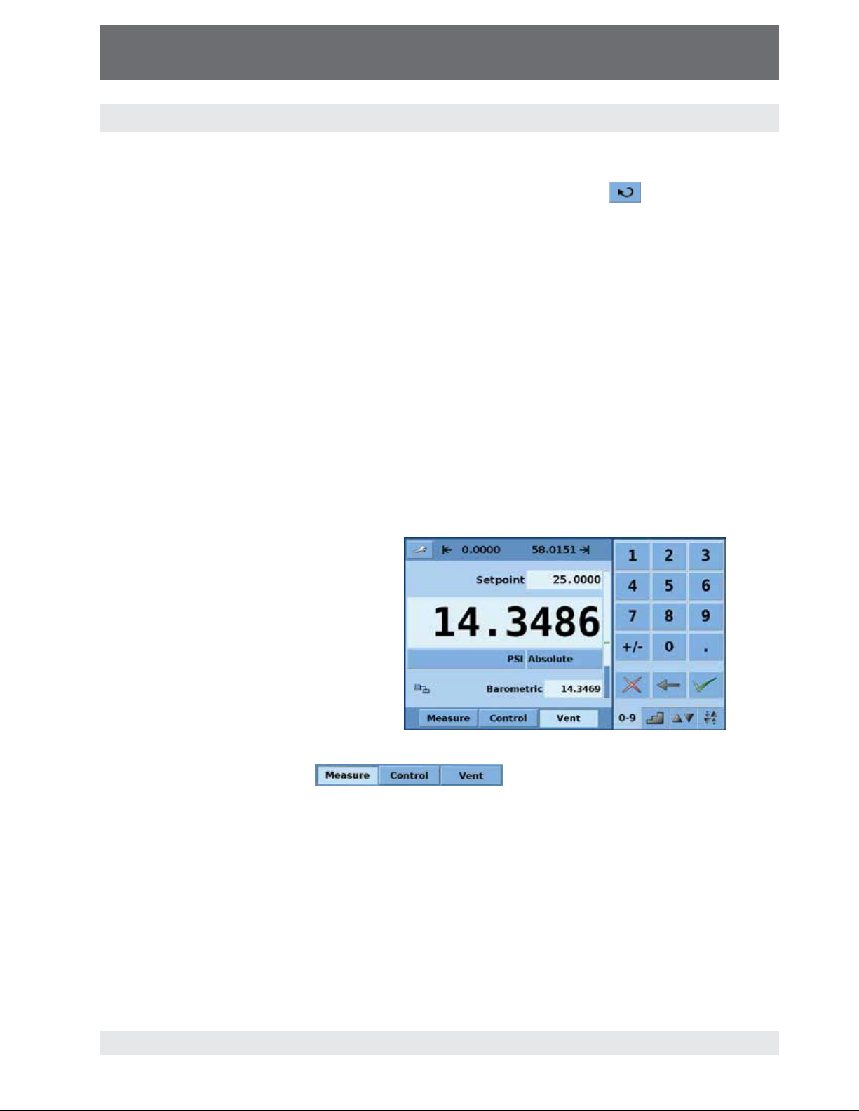
The CPC3000 main menu shown in Figure - "Optional Elements" shows elements that can be
displayed on the main menu and describes the three choices available for setpoint entry (Numeric
Keypad, Step and Jog). Optional elements include the Communication status icon which indicates
a connection or disconnection from a remote computer, and the barometric reference indication
showing the value of the atmospheric pressure measured by the optional internal barometric reference sensor.
used for selecting a setpoint. The [PRESSURE UNIT]
. To change the language
31
Page 32

High-Speed Pressure Controller
CPC3000
Operating Instructions - CPC3000
Setup Key
Setpoint
Stable Indication
Current pressure value
Pressure mode indication
Pressure unit key
Bar graph
User defined DUT / control range
limits (configurable via SETUP)
Numeric keypad
Delete selected setpoint
Delete last entered digit
Accept selected setpoint
MEASURE
Measure mode pneumatically connects
the pressure sensor directly to the device under test. In measure mode pressure regulation is inactive.
SETUP
menu
Pressure emulation mode
key
Communication status
CONTROL
In the control mode, the device
regulates the pressure output
according to the set point value, providing a precise pressure at the measure port.
Figure - Main Menu
VENT
Vents the system and the device
under test to atmospheric pressure.
SETUP menu
The SETUP menu allows
access to the following tabs.
Display
Control
Remote
Info
Service
32
Optional barometric
reference display
jog key pad selection tab
User Defined jog key pad selection tab
Step key pad selection tab
Numeric key pad selection tab
Note: See the following page for detailed information
on each setpoint entry screen.
Figure - Optional Elements
Page 33

High-Speed Pressure Controller
CPC3000
Operating Instructions - CPC3000
7.3 Setpoint entry
The control setpoint can be entered using the default Numeric Keypad or the alternate Step or
Jog keypads that appear on the right side of the main menu when selected using the [SETPOINT
ENTRY SIDE-MENU] tabs
alternative methods of entering the setpoint have advantages in different situations and have been
designed to increase ease of use and productivity.
The Numeric Keypad shown in Figure - "Numeric Keypad" to the left
is the default keypad that appears every time the unit is turned on or
can be activated using the [0-9] tab. A setpoint value can be entered
directly using this keypad. As the value of the setpoint is entered the
setpoint field will turn blue and the entered value will appear in the
field. The setpoint value can be deleted completely using the
[DELETE]
deleted using the [CLEAR ENTRY]
be accepted using the [ACCEPT ENTRY]
[ACCEPT ENTRY] key is pressed the setpoint field will turn white
and the new setpoint will become active. In control mode, the
controller output will ramp to the entered setpoint. Caution: If the
[ACCEPT ENTRY] key is not pressed the previously entered setpoint
will remain active.
on the lower right hand side of the main menu. These
key, the last digit of the entered setpoint can be
key or the setpoint value can
key. When the
Figure - Numeric Keypad
Application:
Direct entry of setpoint using the numeric keypad:
enter the setpoint value and press
Mode the controller will then ramp up the setpoint.
. In Control
100
80
60
40
20
0
Percent of Setpoint
0 1 2 3 4 5
Time (s)
33
Page 34

High-Speed Pressure Controller
CPC3000
Operating Instructions - CPC3000
Figure - Step Keypads
The step keypads shown in Figure "Step Keypads" provide a way to increment the setpoint by defined steps.
Steps are a percent of the user defined
limits set in the main->setup->control
or actual pressure values. A total of
12 steps are provided. When a step is
pressed the related setpoint is immediately entered as the active setpoint. In
control mode, the controller output will
ramp to this setpoint. The Step Keypad
can be modified in the main->setup-
>control menu discussed in section
7.8.2.
Application:
Setpoint entry using the step keypad:
Step changes, automatically calculated as a percent of the user defined full scale limit, or in pressure
units, can be entered by pressing step keys (
) in any sequence.
100
80
60
40
20
Percent of Setpoint
0
Steps changed at operator discretion
34
Page 35

High-Speed Pressure Controller
CPC3000
Operating Instructions - CPC3000
The user defined jog keypad shown in Figure - "User Defined Jog"
provides a way to change the setpoint by a user defined step. The
step is defined by pressing the button showing the current step value.
This opens a number keypad where a new step value can be entered.
Pressing the
step and pressing the
button will increase the setpoint by the defined
will decrease the setpoint by the defined
step.
Application:
Figure - User Defined Jog
Setpoint entry using user
defined jog or jog keypad:
150
200
250
300
350
Use the user defined jog
keypad for quick setpoint
changes.
Use the jog keypad to
100
50
PSI
0
400
450
500
increase or decrease the
setpoint to reach a cardinal
point on a dial gauge.
The jog keypad shown in Figure - "Jog Keypad" provides a way
to jog the setpoint up or down by small steps. The step size is
determined by the resolution, the maximum control limit and/
or the units of measure. For example, if the resolution is set to
display four decimals then the small triangle pointing up will
change the setpoint by 0.0001 and the small triangle pointing
down will change the setpoint by -0.0001. In the same way, the
medium triangles will change the setpoint by +/- 0.0010 and the
large triangles will change the setpoint by +/- 0.0100 as shown
in the figure. When the resolution, the maximum control limit
or the units of measure are changed so that three decimals are
displayed, then the jog functions will change to +/- 0.001, +/-
0.010 and +/- 0.100 respectively. This is useful when adjusting
the controller to reach a cardinal point on a dial gauge.
Figure - Jog Keypad
35
Page 36

High-Speed Pressure Controller
CPC3000
Operating Instructions - CPC3000
7.4 Operating modes
The selection keys for the operating modes Measure, Control and Vent are located at the bottom
of the main menu.
[MEASURE]:
In measure mode, the instrument measures the pressure connected to the MEASURE/
CONTROL port. Figure -"Measure Mode" shows the state of the isolation valves in measure
mode.
When the CPC3000 is turned off all the valves close and could trap
!
Warning
pressurized gas within the pneumatics. It is safe practice to vent after use
and before connecting any devices to the Measure/Control port.
36
Figure - Measure Mode
Page 37

High-Speed Pressure Controller
CPC3000
Operating Instructions - CPC3000
[CONTROL]:
In control mode, the instrument provides a precise pressure output at the Measure/Control port.
The indication of the current pressure value will turn green when the setpoint has been reached
and the stable window settings have been satisfied. Figure -"Control Mode" shows the state of
the isolation valves in measure mode. Notice that the regulator is active in the control mode.
Figure - Control Mode
37
Page 38

High-Speed Pressure Controller
CPC3000
Operating Instructions - CPC3000
[VENT]:
Vent mode vents the pneumatic system and shuts off the supply. Figure -"Vent Mode" shows
the state of the isolation valves in vent mode.
38
Figure - Vent Mode
Page 39

High-Speed Pressure Controller
CPC3000
Operating Instructions - CPC3000
7.5 Data entry
When there is a requirement to enter specific
numeric or alpha values into the system, the
method of entry is consistent for all instances.
When a [VALUE ENTRY] key is pressed a dialog
box will appear similar to Figure - "Value Entry".
This value entry dialog box will have a numeric
or alpha keypad, when appropriate minimum
and maximum value limits, current value and a
window that shows the new value entered. The
value can be deleted completely using the
[DELETE]
setpoint can be deleted using the [CLEAR
ENTRY]
accepted using the [ACCEPT ENTRY]
7.6 "Pressure unit", "pressure mode" and "emulation mode"
The Pressure [UNIT] key is shown on the main menu screen below the current pressure value
and displays the most recently chosen pressure units and the mode (absolute or gauge). If the
optional barometric reference is installed a [MODE] key replaces the mode indication to the right
of the units key. This [MODE] key indicates absolute or gauge mode. When the key is pressed it
will switch between the "native mode" of the internal sensor to the emulation mode. The "native
mode" is the mode of the sensor that is installed and is either absolute or gauge. Emulation mode
uses the value of the barometric reference to emulate the mode that is alternate to the native
mode. The CPC3000 can emulate gauge from a native absolute sensor or absolute from a native
gauge sensor. The [MODE] key indicates the native mode with a blue key background and emulation mode with a light blue key background. The units and mode chosen remain the same when
the CPC3000 is turned off and then back on.
key, the last digit of the entered
key or the setpoint value can be
key.
Figure - Value Entry
Native sensor is gauge, no barometric reference installed.
Native sensor is gauge, barometric reference installed.
Native sensor is gauge, barometric reference installed and
absolute emulation active.
Pressing the [UNITS] key will open a dialog box that shows the available pressure units with tabs
for [ENGLISH], [METRIC] and [USER UNITS]. Pressing a tab will open a menu with the related
set of units available. The [USER UNITS] tab menu includes [USER 1] and [USER 2] keys and
allows the user to enter customized pressure units. Press the [MULTIPLIER VALUE] key to enter
a multiplier that defines the user unit as the multiplier times one psi or one Pascal, whichever is
currently pressed.
A light blue background on a [PRESSURE UNITS] key indicates that it is the current selection.
Touch any other [PRESSURE UNITS] key, and press the [BACK] key to enable change and return
to the previous operation screen. All of the displayed pressure values will have changed to correspond to the newly selected units.
39
Page 40

High-Speed Pressure Controller
CPC3000
Operating Instructions - CPC3000
7.7 Bar chart
The bar chart shows the relative indication
of the current pressure value with respect
to the full scale value of the internal
sensor and the user defined minimum
and maximum limits (see section 7.8.2
for setup of user defined limits). The full
height of the bar graph is proportional to
the internal sensor range. The green line
indicates the magnitude of the setpoint.
The blue column indicates the magnitude of the current pressure. The cross
hatched section indicates the portion of
the internal sensor above or below the
user defined limits that is not being used.
7.8 Setup menus
portion of the internal sensor range
outside of the user defined limits
Setpoint (green line)
internal sensor range
User defined limits
Current pressure
The setup menus are opened by pressing the [SETUP]
Figure - "Setup". The setup menu has five tabs: [DISPLAY], [CONTROL], [REMOTE], [INFO] and
[SERVICE]. Each tab is described in detail in the following sections. The screen below has the
[DISPLAY] tab active.
Figure - Setup
key. This opens the menu shown in
40
Page 41

High-Speed Pressure Controller
CPC3000
Operating Instructions - CPC3000
7.8.1 Setup display
The main->setup->display menu contains elements that change the appearance and function of
components displayed on the main menu. Following is a description of the elements of this menu.
Filter: The filter selection keys [LOW], [NORMAL], and [HIGH] dampen the pressure
display to reduce the affect of pneumatic noise associated with the device under test
or the test environment.
Resolution: The resolution section of the Setup Display menu allows the user to
change the resolution of the current pressure reading to be [4], [5] or [6] digits.
Stable window and delay: The stable window is the percentage of the full scale
value of the internal sensor that the current pressure can deviate +/- from the setpoint
and still display a stable indication. The stable delay is the number of seconds that
the instrument must remain within the stable window before the stable indication is
displayed.
Language: The "View" section of the setup display menu shows a flag, and a
language on a key. This is the current language. Press this key to access a menu
containing other languages that are available. Figure - "Languages" below shows the
language selection screen with the currently available languages shown.
Brightness setting: The brightness slide control provides a way to adjust the screen
brightness.
Speaker check box: This check box enables or disables an audio feedback when
pushing any button. One "beep" audibly designates a legal entry and a double "beep"
audibly designates an attempt to enter an illegal value.
Remote status check box: The Remote status check box enables or disables the
remote status icon on the main menu. This icon will show a broken wire when there is
no connection to a remote computer or a connected wire if the computer is connected.
Barometer (optional): The Barometer check box is under the "View" section and
enables or disables the indication of the barometric pressure on the main menu.
Figure - Languages
41
Page 42

High-Speed Pressure Controller
CPC3000
Operating Instructions - CPC3000
7.8.2 Setup Control
Configuration of parameters associated with setting limits and adjusting parameters used to
control pressure are configured in the Main->Setup->Control menu shown in
Figure - "Setup Control".
Figure - Setup Control
Maximum and minimum control limits: The [DATA ENTRY] keys above the "Step
Range" label in Figure - "Setup Control" allow the operator to enter a "user defined
range" within the full scale range of the internal sensor. For example, if the CPC3000
has a 0-100 psi internal sensor, the user can define a range of 0-50 psi. When the
user defined range is changed, the step menu automatically adjusts so that the
percent step equals a percentage of the user defined range. Example: 80% value of
a 0-50 psi user defined range is 40 psi; for a user defined range of 0-100 the 80%
value equals 80 psi. The user defined range can be set to the same range as the
pressure device being tested. This is useful when there is a test that requires
calibration at intervals equal to a percentage of the range. Each individual step
can also be changed by pressing the [step]
PSI or %F.S.: The [SELECTED UNITS] and [%F.S.]
the step keypad display in the main menu and on the setup screen from the user
selected units to percent of the full scale of the
user defined range. The values when shown in the
[SELECTED UNITS] mode correspond to the
values in the [%F.S.] mode. For example, in Figure
- "PSI Mode", the [PSI] key is pressed and the value shown in the
100% step is 50, corresponding to the maximum limit chosen in
this same screen. Individual steps in "%F.S." or "Selected Units"
mode can be included or excluded from the step menu by
changing the [CHECK BOX]
next to the step.
key and entering a new value.
keys switch
Figure - PSI Mode
42
Page 43

High-Speed Pressure Controller
CPC3000
Operating Instructions - CPC3000
[Preset Points] key allows the operator to select the number of points that appear
as steps. For example, in Figure - "Preset Points" [5] is entered as the preset points
value.This automatically configures 5 points from 0 to 100% of user defined range. It
automatically calculates the steps that populate the step keypad in the main menu.
Figure - Preset Points
[Percent Overrange] The percent overrange key allows a step or control input point
to within a set percentage outside of the user defined range. This is useful when a
pressure gauge is reading low and the controller must be set higher to reach a cardinal point on the gauge.
[High Speed] When checked the controller will control the pressure output to the
setpoint as quickly as conditions allow. When unchecked the controller will control to
the setpoint more slowly but will have minimal or no overshoot.
7.8.3 Setup remote
Configuration of parameters associated with remote communication are set up in the
Main->Setup->Remote screen. Detailed information on setup of Ethernet USB and IEEE-488 are
given in section 8, Remote Operation.
Figure - Setup Remote
43
Page 44

High-Speed Pressure Controller
CPC3000
Operating Instructions - CPC3000
The [ETHERNET SETUP] key opens a dialog box where host name, IP, netmask,
gateway, port, and client IP can be entered. There is also a check box that will
activate (checked) or deactivate (unchecked) Dynamic Host Configuration Protocol
(DHCP). DHCP is a protocol used by networked devices (clients) to obtain the
parameters necessary for operation in an Internet Protocol network. This protocol
reduces system administration workload, allowing devices to be added to the network
with little or no manual configuration.
The [USB SETUP] key opens a dialog box where baud rate (9600, 19200, 38400,
57600, or 115200), data bit (7 or 6), stop bit (1 or 2), and parity (none, odd or even)
can be chosen. There is also a check box that turns echo on (checked) or off
(unchecked).
The [IEEE ADDRESS DATA ENTRY] key opens a data entry dialog box where the
IEEE address can be entered.
In the Communication section there are three remote "command set" emulation
settings. The [MENSOR] key enables the standard Mensor command set, the
[SCPI WIKA] key enables the WIKA SCPI (Standard Commands for Programmable
Instrumentation) command set structure, and the [DPI510] key enables the command
set that will communicate with the Druck DPI 500 series of controllers. In this section
there is also a [REMOTE MONITOR] key that will open a screen that shows the most
recent commands and responses sent and received plus any errors. Details of each
command set are given in section 8.5.
7.8.4 Setup info
The Main->Setup->Info screen, Figure - "Setup Info", provides Mensor contact information plus
the model number, serial number, min and max range and the native pressure units of the internal
sensor, date of calibration and the software version installed. This is an information screen only
and does not contain any interactive keys.
44
Figure - Setup Info
Page 45

High-Speed Pressure Controller
CPC3000
Operating Instructions - CPC3000
7.8.5 Setup service
The Main->Setup->Service screen is a password protected area where calibration of the sensor
and setup of the regulator is accomplished.
Figure - Setup Service
7.8.5.1 Zero (non password protected)
The Main->Setup->Service screen allows zero adjustment without entering the password. For
an absolute sensor a zero adjustment screen, Figure - "Zero", opens when the [Zero] button is
pressed. A new zero value corresponding to a true pressure applied at the Measure/Control port
can be entered in this screen. For gauge sensors, the sensor is automatically vented and "zeroed"
at the current atmospheric pressure. In the latter case the zero adjustment screen does not appear.
Figure - Zero
45
Page 46

High-Speed Pressure Controller
CPC3000
Operating Instructions - CPC3000
7.8.5.2 Unlock setup for calibration and regulator adjustment
To access the password protected portion of the Main->Setup->Service screen press the yellow
[KEY] icon
red [KEY] icon
can only be accessed using a factory supplied password. Adjustment of the regulator Seal Point,
Linearization and Adaptation should only be necessary in situations where external conditions are
outside of the specified limits (example: high volume applications). Adjustment of these parameters should only be done with supervision from Mensor Customer Service.
Both [KEY] icons open a password entry screen, Figure - "Password". The Sensor section default
password is 123456. Entering the sensor section password will open the Main->Setup->Service
screen with the buttons unlocked indicating free access to these selections, Figure - "Setup
Service Unlocked".
!
Warning
to unlock the sensor section to perform calibration of the internal sensors. The
is available to unlock the regulator section, however, the regulator parameters
Consult factory before changing any Seal Point, Linerization or Adaptation
parameters.
46
Figure - Password
Page 47

High-Speed Pressure Controller
CPC3000
Operating Instructions - CPC3000
Figure - Setup Service Unlocked
7.8.5.3 Change Password
The [CHANGE PASSWORD] opens the Change Password screen, Figure - "Change Password"
which allows the owner to change the default password (123456) to a "user" password. This
"user" password should be recorded in a safe location to allow authorized changes and secure the
instrument from unauthorized changes to the calibration parameters.
Enter a new value in the Change Password screen and accept the value by pressing the [ACCEPT
ENTRY]
key. This new value deletes and replaces the default password.
Figure - Change Password
47
Page 48

High-Speed Pressure Controller
CPC3000
Operating Instructions - CPC3000
7.8.5.4 Calibrate sensor or optional barometer
The [CALIBRATE] key provides access to the calibration screen for the internal sensor. If the
optional barometer is installed the [BAROMETER] key provides access to the barometer calibration screen (see Figure - "Setup Service Unlocked" for key location). Both processes are identi-
cal except for the range of the sensor.
Figure - "Calibration Setup" is a pneumatic schematic for a typical calibration.
48
Figure - Calibration Setup
Page 49

High-Speed Pressure Controller
CPC3000
Operating Instructions - CPC3000
7.8.5.4.1 Calibration data
Figure - "Calibrate Data" shows the screen that appears when the [CALIBRATE] key is pressed.
Figure - Calibrate Data
The Calibrate screen contains three tabs: [DATA], [EDIT] and [CALIBRATE]. When entering the
calibrate screen the first time the [DATA] tab is the default. The Data screen allows changes to be
made to the [ZERO], [SPAN], [DATE OF CALIBRATION] and displays the sensor reading and the
serial number. It also allows the mode to be changed between [MEASURE] and [VENT].
49
Page 50

High-Speed Pressure Controller
CPC3000
Operating Instructions - CPC3000
7.8.5.4.2 Edit calibration
The screen accessed by pressing the [Edit] Tab, Figure - "Calibration Edit", allows calibration
using data available from a previous calibration. An example of this is when an "as-found calibration" is performed. Data from the "as-found calibration" can be used to make a "zero and span"
adjustment to the sensor. The data indicating the pressure applied by the primary standard and
the pressure measured by the CPC3000 transducer from the as-found calibration must be available. The lower pressure applied by the standard (the "zero") should be less than 20% FS and the
high pressure applied by the standard (the "span") should be greater than 80% FS.
To edit the calibration from the as-found calibration data:
1. Enter the pressures applied by the standard in the "Desired" column by pressing the corresponding number on the screen (use row 1 for the "zero" value and row 2 for "span" value).
2. Enter the pressure measured by the CPC3000 sensor in the "Actual" column by pressing the
corresponding number on the screen (use row 1 for the "zero" value and row 2 for "span"
value).
3. When the values are changed, an [Apply] key will appear on the screen. Press the [Apply] key
to save the calibration data and apply the correction to the "zero" and "span".
50
Figure - Calibration Edit
Page 51
High-Speed Pressure Controller
CPC3000
Operating Instructions - CPC3000
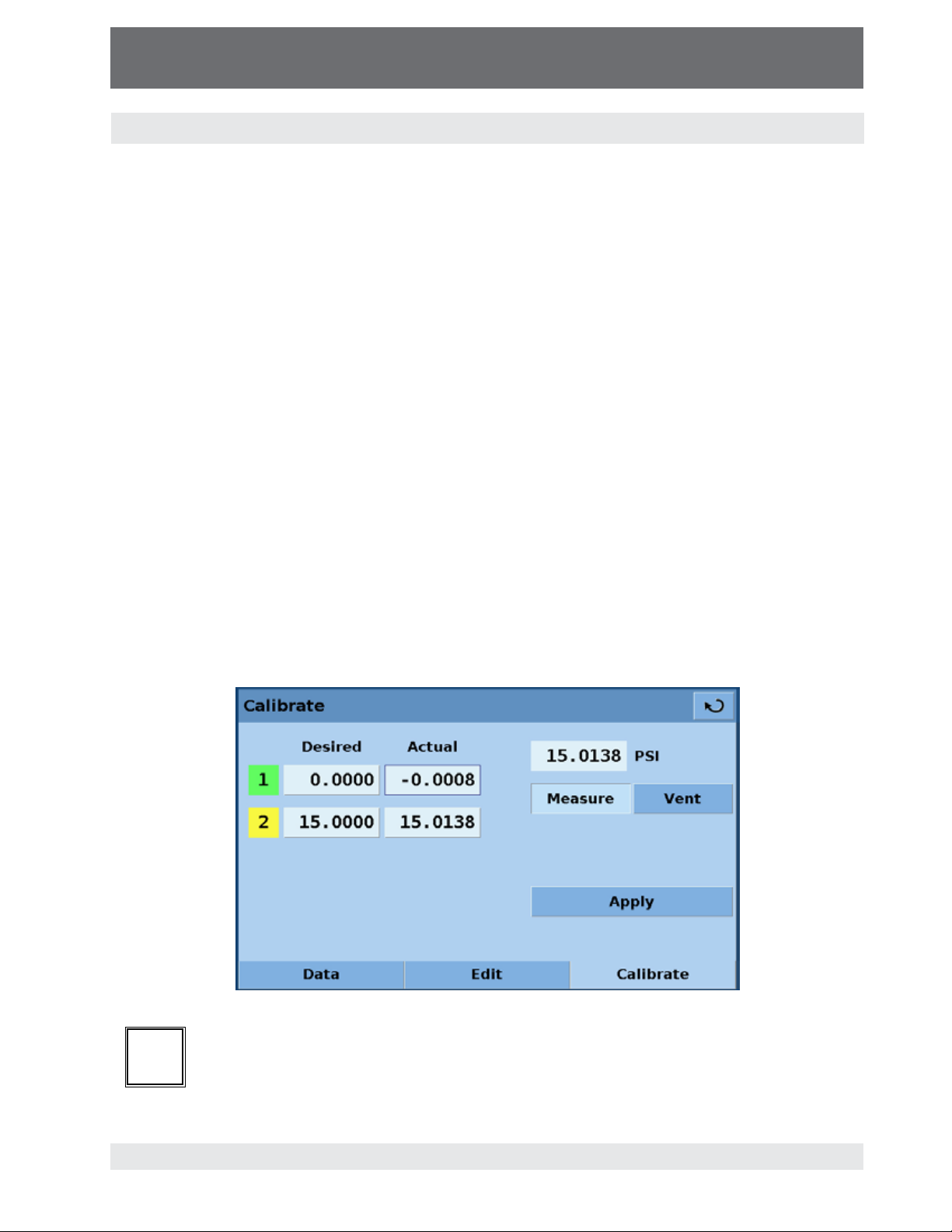
7.8.5.4.3 Live calibration
The Screen accessible by pressing the [Calibrate] tab, Figure - "Calibrate Calibrate", allows the
operator to perform a live calibration while connected directly to a primary standard. The primary
standard should be able to generate a "zero" pressure that is less than 20% of the full scale value
of the sensor in the CPC3000 and a "span" pressure that is greater than 80% of the full scale
value of the sensor in the CPC3000. For best results, the two points should be as close to the end
points of the sensor’s range as possible.
To perform a live "zero" and "span" calibration:
1. Put the CPC3000 in Measure mode by pressing the [MEASURE] key.
2. Using row 1 for the "zero" value and row 2 for "span" value, enter the pressure generated by
the primary standard in the "Desired" column (pressing the number in the "Desired" column will
open a data entry screen). This is the value of the pressure applied to the CPC3000 Measure/
Control Port. For a gauge sensor the "zero" point can be accomplished simply by pressing the
[VENT] key thus venting the CPC3000 sensor to atmospheric pressure.
3. The CPC3000 will display the measured pressure in the "Actual" column, but only after the
measured pressure is within +/- 3.0 % FS of the value in the "Desired" column. At this point
the row number highlight will turn yellow and the value will be displayed in a key.
4. When the pressure displayed on the key in the "actual' column is stable, press this key. This
action serves to accept the value; as a result, the key will change to a label and display the
accepted data. In addition, the row number highlight will change from yellow to green indicating that the number has been accepted.
5. After the "zero" (row 1) and "span" (row 2) have been accepted, press the [APPLY] key to save
changes.
Figure - Calibrate Calibrate
When calibrating an absolute transducer, set the low calibration point at or above a
i
Notice
pressure of 600 millitorr. At or above that pressure the system will have a viscous flow
so that the entire system should have the same pressures after a few minutes.
51
Page 52

High-Speed Pressure Controller
CPC3000
Operating Instructions - CPC3000
8. Remote operation
8.1 Remote setup
To set up any of the remote communication protocols start in the Main->Setup->Remote screen,
Figure - "Setup Remote".
Figure - Setup Remote
8.2 Remote setup – Ethernet
The Ethernet communication port allows the CPC3000 to communicate with computers using
10/100 Bases-T specification. Ethernet communications are transmitted over a standard RJ-45
cable. Connecting directly to a PC requires a crossover Ethernet cable. Hub or router connections
require a straight Ethernet cable.
Before using Ethernet communication, four parameters must be set up: IP, Netmask, Gateway
and Port. In Figure - "Ethernet Setup" the Main->Setup->Remote->Ethernet setup screen is
shown. Each value entry key opens an alpha or numeric data entry screen to change values of the
Ethernet parameters.
52
Figure - Ethernet Setup
Page 53

High-Speed Pressure Controller
CPC3000
Operating Instructions - CPC3000
8.3 Remote setup – USB
The USB communication port allows the CPC3000 to communicate with computers using a USB
cable. The connection on the back panel of the CPC3000 is a Type B recepticle. The USB Driver
can be downloaded at http://www.mensor.com/download_software_instrument_en_um.WIKA.
Figure - USB Setup
8.4 Remote setup – IEEE-488
The IEEE-488 communication port allows the CPC3000 to communicate with computers using an
IEEE-488 cable. This screen, Figure - "IEEE-488 Address", is accessed by pressing the IEEE-488
numeric value box in the Main->Setup->Remote screen. After pressing the numeric value box a
number entry keypad will appear for entering the new IEEE-488 address. The manufacturer of the
host IEEE-488 interface board provides software to allow communication between the board and
various programming languages. An interactive program for debugging is usually provided as well.
Refer to the board manufacturer’s documentation for more information.
FIgure - IEEE-488 Address
53
Page 54

High-Speed Pressure Controller
CPC3000
Operating Instructions - CPC3000
8.5 Remote command set
This remote command set is the default set available on the CPC3000. All CPC3000 remote
operation commands are included in the lists below. All commands must be terminated with a
<cr> or a <lf>.
For a query command (ends with a ?), the Data column represents the response of the CPC3000.
All response strings begin with a space character or an “E” representing that there is an error in
the CPC3000 error queue. All response strings are terminated with a <cr> and a <lf>. The error
queue holds the last 10 errors identified by the CPC3000.
For all commands without a question mark (?), the data column represents the required parameters to be sent to the CPC3000 following the string in the command column. For any command
that requires multiple parameters to be sent to the CPC3000, the parameters must be separated
by commas.
8.5.1 Mensor command set
Command Data Response/Function
? See Table Below Returns data per the current
Acquire? 15 char string.
Address 0-31 Sets the GPIB Address.
Address? <sp>xx<cr><lf> Returns the GPIB Address.
A? <sp>n.nnnnnE+nn<cr><lf> Returns the A channel
AR? <sp>n.nnnnnE+nn<cr><lf> Returns the A channel rate.
ARS? <sp>(Yes or No)<cr><lf> Returns the A channel rate
AS? <sp>(Yes or No)<cr><lf> Returns the A channel stable
Baro? <sp>n.nnnnnE+nn<cr><lf> Returns reading from
Barocaldisable Yes or No Sets whether or not the
Ex:
Acquire? Test_stand_1
Returns:
<sp>(Yes or No), CCC…
CCC<cr><lf>
output format.
This command is used when
multiple computers would like
to control the instrument.
Yes if acquisition is successful, No if instrument is being
controlled with another
computer.
CCC… = name of controlling
computer
See: Release? and Unlock
pressure reading.
stable flag.
flag.
barometric sensor. (Note:
barometric sensor is optional).
calibration of the barometric
sensor is disabled. (Note:
barometric sensor is optional).
54
Page 55

High-Speed Pressure Controller
CPC3000
Operating Instructions - CPC3000
Barocaldisable? <sp>(Yes or No)<cr><lf> Returns whether or not the
calibration of the barometric
sensor is disabled. (Note:
barometric sensor is optional).
Caldisable Yes or No Sets whether or not calibra-
tion of the active sensor is
disabled.
Caldisable? <sp>(Yes or No)<cr><lf> Returns whether or not
calibration of the active
sensor is disabled.
Cerr None Clears the error queue.
CID? Returns the ID string of
the regulator for the active
channel.
Cmdset Mensor, DPI510, DPR60c,
SCPI
Cmdset? <sp>X<cr><lf> Returns active command set
Control Instrument placed in Control
Control? <sp>(Yes or No)<cr><lf> Returns Yes if instrument is in
Ctype? <sp>HSPC<cr><lf> Returns the type of regulator
Decpt? <sp>n<cr><lf> Returns the number of
Default None Sets the default values.
DHCP Reserved for DHCP setup
DHCP? Reserved for DHCP setup
DIO Integer 2 turns on digital output, 0
DIO? Bit 0 = input, bit 1 = output
DOC mm/dd/yyyy Sets the date of cal for the
DOC? <sp>mm/dd/yyyy<cr><lf> Returns the date of cal for the
DOM? <sp>mm/dd/yyyy<cr><lf> Returns the date of manufac-
Error? <sp>text message<cr><lf> Returns the next error in the
Errorno? <sp>Enn-text<cr><lf> Returns pcs400 error code
Activates remote command
set for instrument emulation
modes.
identifier.
Mode.
control, No if otherwise.
for the active channel.
decimal points for the active
channel.
(see Resolution)
turns it off.
active sensor and turndown.
active sensor and turndown.
ture.
error queue.
and text.
55
Page 56

High-Speed Pressure Controller
CPC3000
Operating Instructions - CPC3000
Filter Off, Low, Normal, High Sets the reading filter
Filter? <sp>(filter)<cr><lf> Returns the reading filter.
Gateway nnn.nnn.nnn.nnn Sets the Ethernet gateway
Gateway? <sp>nnn.nnn.nnn.
Id? <sp>MENSOR,CPC3000,
Install Start software installer.
IP nnn.nnn.nnn.nnn Sets the IP address of the
IP? <sp>nnn.nnn.nnn.
Keylock Yes or No Locks or unlocks keyboard.
Keylock? <sp>(Yes or No)<cr><lf> Returns Yes or No.
List? <sp>Pri,X,X;Sec,X,X;Bar,1<c
Listrange? <sp>PRI,1, min,max,2, min,
LowerLimit Value inside primary xducer
LowerLimit? <sp>n.nnnnnE+nn<cr><lf> Returns the lower control limit
Measure None Instrument placed in Measure
Measure? <sp>(Yes or No)<cr><lf> Returns YES if instrument is
Mode Standby, measure, control,
Mode? <sp>Xxxxxx<cr><lf> Returns the operation mode
Netmask nnn.nnn.nnn.nnn Sets the Ethernet network
Netmask? <sp>nnn.nnn.nnn.
Outform 1 to 7 Sets the output format. (See
nnn<cr><lf>
ssssss,v.v.vv
nnn<cr><lf>
r><lf>
max;SEC,1, min,max,2,
min,max,Bar,min,max<cr><lf>
Range on turndown #1 in
current units.
vent
nnn<cr><lf>
0, 80%, 92%, 95%.
address.
Gets the Ethernet gateway
address.
Ssssss is the serial number,
v.v.vv is the CPC3000
software version.
instrument.
Returns the IP address of the
instrument.
Returns list of available turndowns on installed sensors in
the active channel. X will be
non-existent if the turndown
isn’t available.
Returns the ranges of the
installed sensors for the
active channel.
Sets the lower control limit for
the instrument.
for the instrument in current
units.
Mode.
in measure, No if otherwise.
Sets the operation mode of
the active channel.
of the active channel.
mask.
Gets the Ethernet network
mask.
"8.5.7 - Output Format")
56
Page 57

High-Speed Pressure Controller
CPC3000
Operating Instructions - CPC3000
Outform? <sp>X<cr><lf> Returns the output format.
(See "8.5.7 - Output Format")
Overrange value Sets overrange to value.
Overrange? <sp>n.nnnnne+nn<cr><lf> Returns overrange value.
Peakmax? <sp>n.nnnnnE+nn<cr><lf> Returns the max. pressure
since peakreset was sent.
Peakmin? <sp>n.nnnnnE+nn<cr><lf> Returns the min. pressure
since peakreset was sent.
Peakreset None Resets the peak values.
Port nnnnnn Sets the Ethernet port of the
instrument.
Port? <sp>nnnnn<cr><lf> Returns the Ethernet port of
the instrument.
Ptype Absolute or Gauge Sets the instrument pressure
type – gauge only works if the
optional barometric sensor is
installed.
Ptype? <sp>CCCCC<cr><lf> Returns “Absolute” or
“Gauge” for the pressure type
RangeMax? <sp>XXXXXXX<cr><lf> Returns the maximum range
of the active transducer and
turndown in the current units.
RangeMin? <sp>XXXXXXX<cr><lf> Returns the minimum range
of the active transducer and
turndown in the current units.
Rate? <sp>XXXXXXX<cr><lf> Returns the rate reading of
the instrument in current
units/second.
Rdecpt? <sp>n<cr><lf> Returns the number of rate
decimal points for the active
channel. (see: Resolution)
Release? 15 char string.
Ex:
Release? Test_stand_1
Returns:
<sp>(Yes or No), CCC…
CCC<cr><lf>
Resolution n Sets the number of significant
Resolution? <sp>n<cr><lf> Returns the number of signifi-
Rfilter Value in % Sets the % of the rate filter.
This command is used to
release control of the instru-
ment in a multiple computer
environment.
Yes if release is successful.
No if instrument is being
controlled with another
computer.
CCC… = name of controlling
computer or AVAILABLE
See: Acquire? and Unlock
digits. See decpt?.
cant digits. See decpt?.
57
Page 58

High-Speed Pressure Controller
CPC3000
Operating Instructions - CPC3000
Rfilter? <sp>n.nnnnnE+nn<cr><lf> Returns the rate filter.
Rsetpt Value in current units Sets the rate setpoint.
Rsetpt? <sp>n.nnnnnE+nn<cr><lf> Returns the rate setpoint.
Rfreq Value in frequency Sets rate Butterworth corner
Rfreq? <sp>n.nnnnnE+nn<cr><lf> Returns rate Butterworth
Rwindow Value in current units Sets rate exponential filter
Rwindow? <sp>n.nnnnnE+nn<cr><lf> Returns rate exponential filter
Sbaud 9600, 19200, 38400, 57600 Sets the serial baud rate.
Sbaud? <sp>XXXX<cr><lf> Returns the serial baud data.
Sdata 7 or 8 Sets the serial data bits.
Sdata? <sp>X<cr><lf> Returns the serial data bits
Sensor C,X Sets the active sensor where
Sensor? <sp>C,X<cr><lf> Returns active sensor as
Sensorid? <sp>Mensor QRS,SN
Setpt Value inside upper and lower
Setpt? <sp>XXXXXXX<cr><lf> Returns the control setpoint in
Setpt% Value in % of current range Sets the control setpoint in %
Setptpct Value in % of current range Sets the control setpoint in %
Setptpct? <sp>n.nnnnnE+nn<cr><lf> Returns the current setpoint
Span desired pressure or ? Sets span on active trans-
Span? <sp>XXXXXXX<cr><lf> Returns span scale factor for
Sparity Even, Odd, None Sets the serial parity.
Sparity? <sp>CCCC<cr><lf> Returns the serial parity.
Sstop 1 or 2 Sets the serial stop bits.
XXXXXX,VER V.VV<cr><lf>
limits and inside the range
of the active sensor and
turndown.
frequency.
corner frequency.
window.
window.
number.
C = Primary or Secondary and
X = the turndown.
above.
Returns the active sensor’s
serial number and firmware
version.
Sets the control setpoint for
the instrument.
current units.
of current range.
of current range.
in % of current range.
ducer or for ?, clears previous
value, must be > 50% FS and
has a 1% limit.
active transducer.
58
Page 59

High-Speed Pressure Controller
CPC3000
Operating Instructions - CPC3000
Sstop? <sp>X<cr><lf> Returns the serial stop bits.
Stable? <sp>(Yes or No)<cr><lf> Returns YES if instrument is
stable, or No.
Stabledelay 0 to 65535 Sets the stable time to the
number of seconds specified.
Stabledelay? <sp>XXXXXXX<cr><lf> Returns the stable time.
stabletime 0 to 65535 Sets the stable time to the
number of seconds specified.
Stabletime? <sp>XXXXXXX<cr><lf> Returns the stable time.
StableWin %fs value Sets the stable window as
a %FS for the active sensor
and turndown.
StableWin? <sp>XX<cr><lf> Returns the stable window.
Standby None Instrument placed in Standby
Mode.
Standby? <sp>(Yes or No)<cr><lf> Returns Yes if instrument is in
Standby, No if otherwise.
Step value inside upper and lower
limits and inside the range
of the active sensor and
turndown.
Step- Optional value Jogs the setpoint down one
Step+ Optional value Jogs the setpoint up one
Step? <sp>XXXXXXX<cr><lf> Returns the control step for
Step% Value in % of current range Sets the control step in % of
Steppct Value in % of current range Sets the control step in % of
Steppct? <sp>n.nnnnnE+nn<cr><lf> Returns the current step in %
Step.prog nn Go to step nn.
Step.prog.en Nn,(Yes or No) Enables step nn.
Step.prog.en? nn <sp>(Yes or No)<cr><lf> Returns step nn enable state.
Step.prog.pct Yes or No Sets step units.
Step.prog.pct? <sp>(Yes or No)<cr><lf> Returns step units (% step or
Step.prog.val Nn,value Sets step nn value.
Step.prog.val? nn <sp>n.nnnnne+nn<cr><lf> Returns step nn value.
Step.prog.min value Sets step min range
Step.prog.min? <sp>n.nnnnne+nn<cr><lf> Returns step min range.
Sets the control step size for
the instrument.
step.
step.
the instrument.
current range.
current range.
of current range.
pressure units).
59
Page 60

High-Speed Pressure Controller
CPC3000
Operating Instructions - CPC3000
Step.prog.max value Sets step max range.
Step.prog.max? <sp>n.nnnnne+nn<cr><lf> Returns step max range.
Units Units code or text in table Sets the instrument engineer-
Units? <sp>CCCC<cr><lf> Returns the instrument units
Unlock None Releases Acquire locks. See:
UpperLimit Value inside primary xducer
UpperLimit? <sp>xxxxxxx<cr><lf> Returns the upper control
Vent None Instrument placed in Vent
Vent? <sp>(Yes or No)<cr><lf> Returns Yes if instrument is in
Window Value in current units Sets the exponential filter
Window? <sp>n.nnnnnE+nn<cr><lf> Returns the exponential filter-
Range on turndown #1 in
current units.
ing units. See: "Measurement
Units Table" in section 11,
Appendix.
in a text string.
Acquire? and Release?
Sets the Upper control limit
for the active transducer.
limit for the active transducer.
Mode.
Vent, No if otherwise.
window for the active sensor.
window for the active sensor.
Zero desired pressure or ? Sets zero to set pressure or
for ?, clears previous value.
Zero? <sp>xxxxxxx<cr><lf> Returns zero offset for active
transducer.
8.5.2 PCS 400 commands emulated
Command Data Response/Function
_pcs4 autorange <value> 0 or 1 Not applicable.
_pcs4 autorange? Not applicable.
_pcs4 cal a/d Not applicable.
_pcs4 cal atm Performs pcs400 1 pt cal.
_pcs4 cal span <value> Sets the span of the active transducer to
<value>.
_pcs4 cal zero <value> Sets the zero of the active transducer to
<value>.
_pcs4 cal_disable_off Enables zero or span calibrations if
previously disabled.
_pcs4 cal_disable_on Prevents zero or span calibrations.
60
Page 61

High-Speed Pressure Controller
CPC3000
Operating Instructions - CPC3000
_pcs4 ctrl <value><sp><unitno> Sets control value – will take effect
immediately if instrument is in control
mode.
_pcs4 ctrl? Returns the current control point in
current engineering units.
_pcs4 ctrlmax <value> Sets maximum control value.
_pcs4 ctrlmax? Returns current maximum control
pressure.
_pcs4 ctrlmin <value> Sets minimum control value.
_pcs4 ctrlmin? Returns current minimum control
pressure.
_pcs4 emul? Returns ptype emulation mode.
_pcs4 default Sets default values into instrument.
_pcs4 err? Returns the error number and descrip-
tion.
_pcs4 exhaustp? Returns exhaust pressure.
_psc4 filtersetting Sets the filter %.
_pcs4 filtersetting? Returns the filter %.
_pcs4 filterwindow Sets the filter window.
_pcs4 filterwindow? Returns the filter window.
_pcs4 func ctrl <value> <unitno> Instrument placed in control mode at
<value> pressure in <unitno> units.
_pcs4 func emul Toggles ptype emulation mode.
_pcs4 func F1 Toggles ptype emulation mode.
_pcs4 func meas Instrument placed in measure mode.
_pcs4 func stby <unitno> Instrument placed in standby mode in
<unitno> units.
_pcs4 func vent <unitno> Instrument placed in vent mode in
<unitno> units.
_pcs4 id? Returns instrument ID.
_pcs4 lang PCS2 Sets command set to PCS 200.
_pcs4 list? Returns range list.
_pcs4 opt? Returns option list (old PCS 400 format).
_pcs4 option? Returns option list.
_pcs4 outform <digit> Sets output format.
_pcs4 outform? Returns the current output format.
_pcs4 peakreset Resets peak readings.
_pcs4 peakunit Selects Peak+ or Peak-.
_pcs4 peakunit? Returns Peak+ or Peak-.
_pcs4 rangemax? Returns the maximum pressure of the
active transducer.
61
Page 62

High-Speed Pressure Controller
CPC3000
Operating Instructions - CPC3000
_pcs4 rangemin? Returns the minimum pressure of the
_pcs4 rate Sets the control rate.
_pcs4 rate? Returns the pressure rate.
_pcs4 rateunit Selects the rate units (SEC or MIN).
_pcs4 rateunit? Returns the rate units.
_pcs4 reading? Returns the current pressure.
_pcs4 sourcep? Returns the supply pressure.
_pcs4 span? Returns the stored multiplication factor
_pcs4 stabledelay <value> 1 to 255 Sets the number of consecutive
_pcs4 stabledelay? Returns the number of readings that
_pcs4 stablewindow <value> Sets the pressure window that is used to
_pcs4 stablewindow? Returns the pressure tolerance allowed
_pcs4 stat? Returns Mode and stable flag status
_pcs4 unit <unitno> Sets the instrument to specified
_pcs4 unit? Returns the current engineering units
_pcs4 xducer? Returns the number of the currently
_pcs4 xducerid? Returns information on active sensor.
_pcs4 zero? Returns the stored zero offset of the
active transducer.
from the active transducer & turndown.
readings that the pressure must remain
within the stable window for a pressure
stable indication.
must be within the stable window before
a stable pressure is indicated.
indicate pressure is stable.
for a stable pressure indication as a %
of span of the active transducer.
“mode, stable CR LF”.
engineering units.
and the type of transducer (A, G, D).
active transducer.
active transducer and turndown in the
current pressure units.
8.5.3 PCS 200 commands emulated
Command Response/Function
CX Control Pressure at last control point and units
C$nnnnnnnX Control Pressure at n in units $
C$nnnnnnnsX Control Pressure at n in units $
D#X CAL POINT CONTROL MODE NOT SUPPORTED
EX Clear Error/Clear Service Request
62
Page 63

High-Speed Pressure Controller
CPC3000
Operating Instructions - CPC3000
E?X Return error code and clear error
F$nnnnnnn1X Re-initialize; $,n ignored
F$nnnnnnn2X RETURN CAL DATA NOT SUPPORTED
F$nnnnnnn3X Return Unit ID string; $,n ignored
F$nnnnnnn5X RETURN QPS TEMPERATURE NOT SUPPORTED
F$nnnnnnn6X RETURN NULL METER READING NOT SUPPORTED
F$nnnnnnn1X RETURN VACUUM GAUGE READING NOT SUPPORTED
F$nnnnnnn1X Return Clock Reading (Time); $,n ignored
F$nnnnnnn1X Return Pressure Control Limits; $,n ignored
MX Measure Pressure in current pressure units
M$X Measure Pressure in units specified by $
M$nnnnnnnX Measure Pressure in units specified by $; n ignored
M$nnnnnnnnsX Measure Pressure in units specified by $; n,s ignored
Q#X SEQ FUNCTIONS NOT SUPPORTED
R0X Return to Standard Output Format
R1X Re-initialize
R2X RETURN CAL DATA NOT SUPPORTED
R3X Return unit ID string
R5X RETURN QPS TEMPERATURE NOT SUPPORTED
R6X RETURN NULL METER READING NOT SUPPORTED
R7X RETURN VACUUM GAUGE READING NOT SUPPORTED
R8X Return Clock Reading (Time)
R9X Return Pressure Control Limits (Min and Max)
SX Standby Mode
S$X Standby Mode; $ ignored
S$nnnnnnnX Standby Mode; $,n ignored
S$nnnnnnnsX Standby Mode; $,n,s ignored
U$X Change Units to units specified by $
VX Vent Mode in current units
V$X Vent Mode in units specified by $
V$nnnnnnnX Vent Mode in units specified by $; n ignored
V$nnnnnnnsX Vent Mode in units specified by $; n,s ignored
ZX AUTO RE-ZERO NOT SUPPORTED
63
Page 64

High-Speed Pressure Controller
CPC3000
Operating Instructions - CPC3000
8.5.4 DPI 510 commands emulated
Command Response/Function
Q Return data in output format
A Make the A channel active
M Go to local
R Select active range
S Select preset units
U Set units
D Select output data
F Select function
N Set output format
I Set interrupt conditions
C Select control mode
P Set the control setpoint
/ Setpoint ratio NOT EMULATED
* Setpoint preset NOT EMULATED
W Set the stable time
@ Error Report
V Set rate setpoint
J Rate setpoint preset NOT EMULATED
O Set zero offset
Q (baro) Get baro reading (secondary address 9)
A (baro) Select absolute
G (baro) Select gauge
DCL Device clear
GTL Go to local
IFC Interface clear
64
Page 65

High-Speed Pressure Controller
CPC3000
Operating Instructions - CPC3000
8.5.5 IEEE 488.2 commands
Command Response/Function
*IDN? Return identification string
*RST Reset to known state (DEFAULT+PSI)
*TST? Returns OK
*OPC Operation completed
*WAI Returns operation completed state
*CLS Clear status and error queue
*ESE Enable status event
*ESE? Returns enable status event value
*ESR Event status register
*ESR? Returns event status register value
*SRE Service request enable
*SRE? Returns service request enable value
*STB? Returns status byte
65
Page 66

High-Speed Pressure Controller
CPC3000
Operating Instructions - CPC3000
8.5.6 SCPI commands
Note:
If Wika option is enabled, SCPI units are BARS, otherwise SCPI units are the currently selected
unit.
Command Response/Function
MEASure
[:PRESsure][R]? Returns the pressure from range R
:TEMPerature[R]? Returns the temperature from range R
:RATE[R]? Returns the rate/sec from range R
:BAROmetric? Returns the barometric pressure
[:PRESsure][R]
:MODE? Returns 1=calibrated or 0=not calibrated
:DATE? Returns date of cal “DD,MM,YY”
:DATE <i,i,i> Sets date of cal YYYY,MM,DD
:ZERO? Returns zero offset
:ZERO <n> Sets the zero offset
:ZERO:RUN Same as CAL:ZERO 0
:ZERO:INITiate? Returns zero status
:ZERO:INITiate No function
SENSe
[:PRESsure][R]
:NAME? Returns sensor name string
:MODE? Returns “ABSOLUTE” or “GAUGE”
:MODE ABS|GAUGE Sets pressure type
:ABS? Returns native sensor type 0=GAUGE
:RESolution? Returns resolution (float)
:RANGe
[:UPPer]? Returns maximum range
:LOWer? Returns minimum range
:UNIT
[:NAME]? Returns ASCII units (mixed case)
:VALue? Returns the units conversion factor
:REFerence
[:HEIGht] <n> Sets the head pressure height
:MODE? Returns “OFF”, “GAS”, or “LIQUIT”
:MODE OFF | GAS | LIQUIT Sets the head pressure mode
:MEDium <n> Sets the medium density
1=ABSOLUTE
66
Page 67

High-Speed Pressure Controller
CPC3000
Operating Instructions - CPC3000
SYSTem
:DATE <i,i,i> Sets sytem date YY,MM,DD
:TIME <i,i,i> Sets system time HH,MM,SS
:ERRor[:NEXT]? Returns error code, description
:KLOCk ON | OFF | 1 | 0 Sets the keylock state
:PRESet Load known state values
:SAVe No function (not needed)
:VERSion? Returns SCPI version 1994.0
TEST
:ELECtronic? Returns “OK”
:RELay <n>? Returns status of digital output <n>
ignored
:RELay <n> ON | OFF Turns the digital output on or off <n>
ignored
UNIT
:NAME <n>? Returns the units string for units code
<n>
:FACTor <n>? Returns the units conversion for units
code <n>
OUTPut
:STATe ON | OFF | 1 | 0 ON or 1 = Control OFF or 0 = Measure
:STATe? Returns 0 for measure 1 for control
:MODE MEASure | CONTrol | VENT Sets the mode indicated
:MODE? Returns the mode string
:STABle? Returns 1 if stable 0 if not
:AUTOvent ON | OFF | 1 | 0 Puts the unit in the Vent mode if true
:AUTOvent? Returns the state of the Vent mode
[SOURce]
:PRESsure
[:LEVel]
[:IMMediate]
[:AMPLitude] <n> Sets the setpoint
[:AMPLitude]? Returns the setpoint
:SLEW <n> Sets the rate setpoint
:SLEW? Returns the rate setpoint
:TOLerance? Returns the stable window
:TOLerance <n> Sets the stable window
67
Page 68

High-Speed Pressure Controller
CPC3000
Operating Instructions - CPC3000
CALCulate
:LIMit
:LOWer <n> Set the minimum control limit
:LOWer? Set the minimum control limit
:UPPer <n> Set the maximum control limit
:UPPer? Set the maximum control limit
:SYSTem
:DETECT SLOW | FAST | CANCEL Control autotune (NOT USED NOW)
:DETECT? Returns state of control autotune
8.5.7 Output formats
1. <sp> pressure value <cr><lf>
2. <sp> pressure, units number, mode <cr><lf>
3. <sp> pressure, pressure rate <cr><lf>
4. <sp> pressure, minimum peak, maximum peak<cr><lf>
5. <sp> pressure, active sensor (P or S) active turndown (1-4)<cr><lf>
6. <sp> pressure, control point, “stable” or “slewing”<cr><lf>
7. <sp> pressure, “no barometer” or baro reading<cr><lf>
68
Page 69

High-Speed Pressure Controller
CPC3000
Operating Instructions - CPC3000
9. Trouble-shooting measures
If faults cannot be repaired, the system must be taken out of operation
immediately and protected against unintentional restarting. This information
should be reported to authorized service personnel.
Repairs must only be performed by Mensor or authorized service personnel.
Work on electrical or pneumatic/hydraulic equipment must only be performed
by qualified and authorized service personnel, observing the corresponding
safety regulations.
9.1 Table: Fault description and measures
Type of fault Measures
I. After the system is switched for 60
seconds, no measurement(s) appears,
Switch off the system and then switch back
on again after 5 seconds.
and the entire area of the screen is white
or dark.
II. The screen is dark and the measures for
faults of type I are without effect.
Check that the power cable is connected
properly and have authorized technical staff
check that the supply voltage is correct.
III. The screen is dark and the measures for
faults of type II are without effect.
First pull out the power cable from the power
socket and then from the power supply input
socket of the system. Then pull out the fuse
holder and check the fuses.
Fuse holder
Power supply input socket
IV. Malfunction during operation Switch off the system and switch on again
after 5 seconds.
V. The set value is not reached. Check whether the value of the supply
pressure at the SUPPLY port is the value
required and leak-test the pipe connections.
69
Page 70

High-Speed Pressure Controller
CPC3000
Operating Instructions - CPC3000
If the fuses of the power supply input socket have to be replaced, use
!
Warning
If you require further help please contact Mensor or WIKA at:
3/4 amp Slo-Blo 250V.
Mensor
201 Barnes Drive
San Marcos, Tx 78666
TEL: 512.396.4200
800.984.4200 (USA only)
WEB SITE: www.mensor.com
FAX: 512.396.1820
E-MAIL: sales@mensor.com
tech.support@mensor.com
quality@mensor.com
WIKA Alexander Wiegand SE & Co. KG
Alexander-Wiegand-Straße 30
D-63911 Klingenberg / Germany
TEL: (+49) 93 72/132-9986
WEB SITE: www.wika.de
FAX: (+49) 93 72/132-8767
E-MAIL: testequip@wika.de
70
Page 71

High-Speed Pressure Controller
CPC3000
Operating Instructions - CPC3000
10. Re-calibrating and servicing
We recommend having the system re-calibrated periodically by the manufacturer. Initially, the
recommended period between calibration is as specified (365 days). This period may be extended
as confidence is gained in the span stability.
During the first re-calibration a service file is started automatically in which every re-calibration and
service is recorded.
The CPC3000 requires almost no maintenance, because all moving parts are extremely robust.
There are no parts which have to be serviced by the user.
Before cleaning the surface of the instrument, make sure the instrument
!
Warning
!
is not pressurized, that the power is off and the power supply has been
disconnected.
To clean the touch-screen use only customary plastic or glass cleaning agents
in compliance with the guidelines of the manufacturer.
Caution
71
Page 72

High-Speed Pressure Controller
CPC3000
Operating Instructions - CPC3000
11. Removal of the system
Work on electrical or pneumatic/hydraulic equipment must only be carried out
!
Warning
When dismantling the system proceed as follows:
1. Vent the system and make sure that there is no positive or negative pressure on the system
and that all parts of the instrument are at room temperature.
2. Switch the system off by pressing the power switch located at the rear of the instrument.
3. First pull out the power cable from the power socket and then from the power supply input.
4. Disconnect the pressure connections.
by qualified and authorized service personnel, observing the corresponding
safety regulations.
If a connection to a SWAGELOK
overturning or loosening the SWAGELOK
with suitable tools.
®
- connection is to be disconnected,
®
- connection must be prevented
5. Remove the system as necessary.
6. Protect connections with the protective caps supplied.
72
Page 73

High-Speed Pressure Controller
CPC3000
Operating Instructions - CPC3000
12. Transport of the system
Before the system is shipped it must be clean and free of dirt and debris. This
!
Warning
The CPC3000 must only be shipped in an appropriate transport box. If necessary, please ask for a
proper transport box:
Mensor
Phone 512.396.4200
800.984.4200 in USA and Canada
Fax 512.396.1820
E-mail tech.support@mensor.com
Follow these instructions to prevent damage:
is particularly important if the medium is a health hazard such as a corrosive,
toxic, carcinogenic, radioactive, etc.
WIKA
Phone +49 - (0) 93 72 / 132-9986
Fax +49 - (0) 93 72/132-8767
E-mail testequip@wika.de
Alexander Wiegand SE & Co. KG
1. Wrap the system in anti-static plastic foil.
2. Place the system in the box assuring the instrument is packed tight with insulating material
surrounding the instrument on all sides.
3. If possible add a bag of desiccant to the box.
4. Make sure that the shipment is marked as transport of a highly sensitive measuring instrument.
The shipping address for Mensor and WIKA:
Mensor
201 Barnes Drive
San Marcos, Texas 78666-5994
WIKA Alexander Wiegand SE & Co. KG
Abteilung: Kalibriertechnik CT
Alexander-Wiegand-Straße
D-63911 Klingenberg / Germany
73
Page 74

High-Speed Pressure Controller
CPC3000
Operating Instructions - CPC3000
13. Storage of the system
Before the system is stored it must be clean and free of dirt and debris. This
is particularly important if the medium is a health hazard such as a corrosive,
toxic, carcinogenic, radioactive, etc.
The storage place must satisfy the following conditions:
Storage temperature: 0 to 70 °C
Humidity: 0 to 95% relative humidity without condensation
Avoid the following influences:
Direct sunlight or vicinity to hot objects
Mechanical vibration
Soot, steam, dust and corrosive gases
Explosion-hazard environment, flammable atmosphere
The system should be stored in its original transport box, in a place that meets the conditions
listed above.
Follow these instructions to avoid damage:
1. Wrap the system in anti-static plastic foil.
2. Using the insulating material, place the system in the box.
3. If the system is to be stored for a longer period of time (more than 30 days) add a bag with
desiccant to the box.
74
Page 75

High-Speed Pressure Controller
CPC3000
Operating Instructions - CPC3000
14. Placing out of service
Before the system is shipped it must be clean and free of dirt and debris. This
!
Warning
When placing the system out of service, please dismantle it according to the instructions in the
manual in section 11: "Removal of the system".
i
Notice
is particularly important if the medium is a health hazard such as a corrosive,
toxic, carcinogenic, radioactive, etc.
When disposing of the system please observe the legal and local regulations in
force.
For the final disposal of the system a special firm qualified for this is to be commissioned.
75
Page 76

High-Speed Pressure Controller
CPC3000
Operating Instructions - CPC3000
15. Appendix
Sales and Service International
Table – Measurement Units
Table – Conversion Factors, Pascal
76
Page 77

High-Speed Pressure Controller
CPC3000
Operating Instructions - CPC3000
Sales and Service International
(Service centers shown in bold text)
Europe Europe Europe Europe
Germany
Headquarters:
WIKA
Alexander Wiegand GmbH & Co. KG
Alexander-Wiegand-Str.
63911 Klingenberg
Tel. (+49) 93 72-1 32-0
Fax (+49) 93 72-1 32-406
E-mail: info@wika.de
www.wika.de
Austria
WIKA Messgerätevertrieb
Ursula Wiegand GmbH & Co. KG
Perfektastr. 83
1230 Wien
Tel. (+43) 1- 869 16 31
Fax (+43) 1- 869 16 34
E-mail: info@wika.at
www.wika.at
Benelux
WIKA Benelux
Industrial estate De Berk
Newtonweg 12
6101 WX Echt
Tel. (+31) 475-53 55 00
Fax (+31) 475-53 54 46
E-mail: info@wika.nl
www.wika.nl
Bosnia
GRIZELJ d.d.
Nikole Sopa 46, Ilizda
71000 Sarajevo
Tel. (+387) 33-542992
Fax (+387) 33-457141
E-Mail: grizelj@grizelj.com
www.grizelj.com
RUDEL PROJEKT
Rate Dugojnica 10
75000 Tuzla
Tel. (+387) 35 267 067
Fax (+387) 35 267 067
E-Mail: rudelpro@bih.net.ba
Bulgaria
WIKA Bulgaria EOOD
Blvd. „Al. Stamboliyski“ Nr. 205
1309 Sofia
Tel. (+359) 2 82138-10
Fax (+359) 2 82138-13
E-mail: t.antonov@wika.bg
Croatia
WIKA Croatia d.o.o.
Hrastovičcka19
10250Zagreb-Lucčko
Tel. (+385) 1 6531 034
Fax (+385) 1 6531 357
E-mail: info@wika.hr
Cyprus
Theseas Savva
118, Franklin . Roosevelt Avenue
P.O. Box 114
3601 Limassol
Tel. (+357) 5 - 56 58 99
Fax (+357) 5 - 56 29 17
E-mail: theseas@cytanet.com.cy
Czech Republic
WIKA Representative Office
Dipl.Ing. Rainer Arlt
Ul. Mora Krausza C. 13
SK-94504 Komarno 4
Tel. (+421) 35-7782215
Fax (+421) 35-7852020
E-mail: r.arlt@nextra.sk
ARMEX Holding a.s.
Folknarska 21
40502 Decin II
Tel. (+420) 412-526 500
Fax (+420) 412-526 501
E-mail: obchod@armex.cz
Tertec spol. s.r.o.
Cihelni 95/1191
70200 Ostrava
Tel. (+420) 596-623 157
Fax (+420) 596-613 913
E-mail: info@tertec.cz
Manag a.s.
Stitarska 154
28002 Kolin
Tel. (+420) 321-71 12 94
Fax (+420) 321-72 26 98
E-mail: jiri.novak@manag.com
MaR Systems s.r.o.
Ivana Olbrachta 3998/5A
69503 Hodonin
Tel. +420 518 321669
Fax +420 518 321669
E-mail: obchod@marsystems.cz
G.A.S.a.s
U Kyjovky c. 3928/1
69501 Hodonin
Tel. (+420) 518-700-162
Fax (+420) 518-700-222
E-mail: gas@gas-as.cz
Denmark
Carl A. Plesner A/S
Klintehoej Vaenge 6
Postbox 119
3460 Birkerod
Tel. (+45) 45 81 96 00
Fax (+45) 45 81 96 22
E-mail: carl@plesner.dk
Finland
WIKA Finland Oy
Melkonkatu 24
00210 Helsinki
Tel. (+358) 9-682 49 20
Fax (+358) 9-682 49 270
E-mail: info@wika.fi
www.wika.fi
France
WIKA Instruments s.a.r.l.
Parc d‘Affaires des Bellevues
„Eragny Parc“ Immeuble Colorado
8, Rue Rosa Luxembourg
95610 Eragny-sur-Oise
B.P. 261
95615 Cergy Pontoise Cedex
Tel. (+33) 1-34 30 84 84
Fax (+33) 1-34 30 84 94
E-mail: info@wika.fr
www.wika.fr
Greece
Deka S.A.
Aristidou 21
GR 18531 Pireas
Tel. (+30) 210- 422 23 25
Fax (+30) 210- 411 81 07
E-mail: deka@otenet.gr
www.deka.gr
Hungary
ID. VASILESCU JANOS KFT.
Ipari Meresi Technikai
Export-Import
Schwartzer F. u. 4
1123 Budapest
Tel. (+36) 1-212-3822
Fax (+36) 1-213-8205
Component Kft.
Galamboc u. 45
1119 Budapest
Tel. (+36) 1-206 67 31
Fax (+36) 1-204 01 56
E-mail: info@componentkft.hu
Iceland
Sturlaugur Jonsson & Co. ehf.
Fiskisloo 26
P.O. Box 605
121 Reykjavik
Tel. (+354) 551 46 80
Fax (+354) 552 63 31
E-mail: sturlaugur@sturlaugur.is
Ireland, Republic of
Instrument Technology Ltd.
Unit 6 Dunboyne Business Park
Dunboyne
Co. Meath
Tel. (+353) 1-801 37 70
Fax (+353) 1-801 37 71
E-mail: info@itldub.ie
Italy
WIKA Italiana SRL
Via G. Marconi 8
20020 Arese (Milano)
Tel. (+39) 02-93 86 11
Fax (+39) 02-93 86 174
E-mail: info@wika.it
www.wika.it
Lithuania
Uzdaroji Akcine Bendrove
„Lintera“
Ukmerges Str. 22
LT - 5000 Jonava
Tel. (+370) 349 - 611 61/614 48
Fax (+370) 349 - 612 97
E-mail: lintera@is.lt
Macedonia
TEGA INZENERING d.o.o.
Ul. Kozle 88 B3 mezanin lokal 7
1000 Skopje
Tel. (+389) 2308 6094
Fax (+389) 2308 6095
E-mail: poposki@tegaing.com.mk
Malta
Salvo Grima & Sons Ltd.
12 Barriera Wharf
Valetta
Tel. (+356) 23 22 75
Montenegro
FILCOM
Danila Bojovica BB
81400 Niksic
Tel. (+382) 83 212374
Fax (+382) 83 212374
E-mail: filcom@cg.yu
Norway
Ax Flow-Norsk Pumpe & Gregersen AS
Lilleakerveien 10
P.O. Box 98
0216 Oslo
Tel. (+47) 22 73 67 00
Fax (+47) 22 7367 86
E-mail: arne.vagn.petersen@axflow.no
Poland
WIKA Polska S.A.
UL. Legska 29/35
87-800 Wloclawek
Tel. (+48) 542 30 11 00
Fax (+48) 542 30 11 01
E-mail: info@wikapolska.pl
www.wikapolska.pl
Romania
WIKA Instruments Romania S.R.L.
Bucuresti, Sector 5
Calea Rahovei Nr. 266-268
Corp 61, Etaj 1
Tel. (+40) 21 4048 327
Fax (+40) 21 4563 137
E-mail: m.anghel@wika.ro
Russia
ZAO WIKA MERA
Wjatskaya Str. 27, Building 17
Office 205/206
127015 Moscow
Tel. (+7) 495-648 01 80
Fax (+7) 495-648 01 81
E-mail: info@wika.ru
www.wika.ru
Serbia
WIKA Merna Tehnika d.o.o.
Sime Solaje 15
11060 Beograd
Tel. (+381) 11 27 63 722
Fax (+381) 11 75 36 74
E-mail: info@wika.co.yu
www.wika.co.yu
Slovakia
WIKA Representative Office
Dipl.-Ing. Rainer Arlt
Ul. Mora Krausza c. 13
94504 Komarno 4
Tel. (+421) 35-778 22 15
Fax (+421) 35 78 52 020
E-mail: r.arlt@nextra.sk
MICROWELL spol.s.r.o.
Ul. SNP 2018/40
92700 Sala
Tel. (+421) 31-770 70 82
Fax (+421) 31-770 75 88
E-mail: microwell@microwell.sk
EL-TECHNIK, spol.s r.o.
Budovatelská 63
08001 Presov
Tel. (+421) 51 7733 890
Fax (+421) 51 7733 890
E-mail: fortuna@eltechnik.sk
Slovenia
Materm d.o.o.
Morje 159 b
2313 Fram
Tel. (+386) 2 6089 014
Fax. (+386) 2 6089 018
E-mail: m.zgalin@siol.net
Termocenter d.o.o.
Zaloska Cesta 149
77
Page 78

High-Speed Pressure Controller
CPC3000
Operating Instructions - CPC3000
Sales and Service International
(Service centers shown in bold text)
1000 Ljubljana
Tel. (+386) 1 5406581
Fax (+386) 1 5400408
E-mail: info@termocenter-tps.si
Spain
Instrumentos WIKA, S.A.
C/Josep Carner, 11-17
08205 Sabadell (Barcelona)
Tel. (+34) 902 902 577
Fax (+34) 933 938 666
E-mail: info@wika.es
www.wika.es
Sweden
AB Svenska Industri Instrument
Exportgatan 38D
Box 8923
40273 Göteborg
Tel. (+46) 31-742 56 00
Fax (+46) 31-742 56 01
E-mail: info@sini.se
www.sini.se
Switzerland
Manometer AG
Industriestrasse 11
6285 Hitzkirch
Tel. (+41) 41-919 72 72
Fax (+41) 41-919 72 73
E-mail: info@manometer.ch
www.manometer.ch
Ukraine
WIKA Pribor GmbH
Ul. Kujbischeva 63-A
83016 Donetsk
Tel. (+38) 062 / 345 34 17
Fax (+38) 062 / 345 34 16
E-mail: info@wika.donetsk.ua
www.wika.donetsk.ua
United Kingdom
WIKA Instruments Ltd
4 Gatton Park Business Centre
Wells Place
Merstham, Redhill RH1 3LG
Tel. (+44) 1737 644 008
Fax (+44) 1737 644 403
E-mail: info@wika.co.uk
www.wika.co.uk
North America Central/South AmericaEurope
Canada
WIKA Instruments Ltd.
Head Office
3103 Parsons Road
Edmonton, Alberta, T6N 1C8
Tel. (+1) 780-463 70 35
Fax (+1) 780-462 00 17
E-mail: info@wika.ca
www.wika.ca
USA
WIKA Instrument Corporation
1000 Wiegand Boulevard
Lawrenceville, GA 30043
Tel. (+1) 770-513 82 00
Fax (+1) 770-338 51 18
E-mail: info@wika.com
www.wika.com
Mensor (Sales and Service)
201 Barnes Drive
San Marcos, TX 78666
Tel. (+1) 512-396 4200-15
Fax (+1) 512-396 1820
E-mail: sales@mensor.com
www.mensor.com
Argentina
WIKA Argentina S.A.
Gral. Lavalle 3568
(B1603AUH) Villa Martelli
Buenos Aires
Tel. (+54) 11 4730 18 00
Fax (+54) 11 4761 00 50
E-mail: info@wika.com.ar
www.wika.com.ar
Brazil
Wika do Brasil Ind. e Com. Ltda.
Av. Ursula Wiegand, 03
Poligono Industrial
CEP 18560-000 Iperó - SP
Tel. (+55) 15-3459 9700
Fax (+55) 15-3266 1650
E-mail: marketing@wika.com.br
www.wika.com.br
Chile
Veto y Cia Ltda.
San Eugenio N°567
Nunoa - Santiago, Zip Code 7780008
P. O. Box 10289
Tel. (+56) 2 355 44 00
Fax (+56) 2 355 44 55
E-mail: andres.veto@veto.cl
www.veto.cl
Colombia
Flexilatina de Colombia Ltda.
Transversal 40, No. 20 - 53
Apartado Aéreo 20216
Santafé de Bogotá
Tel. (+571) 269 09 50
Fax (+571) 283 49 74
E-mail: ventas@flexilatina.com
Costa Rica
Central de Mangueras, S.A.
150 Metros Oeste de La Plaza de
Deportes de La Uruca
San José
P.O. Box 241-1150
La Uruca
Tel. (+506) 256-1111
Fax (+506) 222-8513
E-mail: ventas@centraldemangueras.
com
FLOTEC SA
P.O. Box 774-1007, San Jose-Costa Rica
Tel. (+506) 221-5559
Fax (+506) 223-8457
E-Mail: flotec@racsa.co.cr
Dominican Republic
Garlas Controls
Euclides Morillo No. 55
Aroyo Hondo
Santo Domingo
Tel. (+809) 563-3226
Fax (+809) 563-3498
E-mail: juangarcia@garlascontrol.com
Central/South America
El Salvador
Valvulas y Equipos/Indelpin S.A. de C.V.
Res. Escalon Nte.
Calle El Escorial y Avenida Los Encinos
Block B. No. 14
San Salvador
Tel. (+503) 262-2680
Fax (+503) 262-0361
E-mail: valvulasyequipos@integra.com.sv
Ecuador
Disetec
Av. Eloy Alfaro N52-225 y Capitan
Ramon Borja
Quito
Tel. (+593) 2-328 12 55
Fax (+593) 2-328 12 77
E-mail: disetec@interactive.net.ec
Guatemala
Maquinara e Insumos Industriales, S.A
(MAQUINSA)
10 Calle 0-78 Zona 14
Plaza San Judas Oficina 201
01014 Guatemala
Tel. (+502) 363-19 86
Fax (+502) 363-20 26
E-mail: maquinsa@intelnet.net.gt
Jamaica
B.J. Hanna & Sons Ltd.
7 Retirement Crescent
Kingston, Jamaica W.I.
Tel. (+876) 960-48 90
Fax (+876) 960-48 95
T.M. & T. Associates Ltd.
33 Ward Ave.
P.O. Box 322
Mandeville, Jamaica W.I.
Tel. (+876) 962-53 44
Fax (+876) 962-94 09
E-mail: heavent@cwjamaica.com
Mexico
Instrumentos WIKA Mexico S.A. de C.V.
Av. Santa Fe 170 oficina 6-2-18
Lomas de Santa Fe
Alvaro Obregon
01210, Mexico D.F.
Tel. (+52) 55-5020 5300
Fax (+52) 55-5020 5301
E-Mail: ventas@wika.com
www.wika.com.mx
Nicaragua
Buhler Bandas y Mangueras
C. Norte, Cerveceria Victoria 2 1/2 c.
Arriba
P.O. Box 2358
Managua
Tel. (+505) 249-36 16
Fax (+505) 276-00 44
E-mail: buhler@ns.tmx.com.ni
78
Page 79

High-Speed Pressure Controller
CPC3000
Operating Instructions - CPC3000
Sales and Service International
(Service centers shown in bold text)
Central/South America Australia Africa
Panama
Accesorios Industriales
AV. Ricardo J. Alfaro, EDIF. Metales, APDO
0819-08369
Panama City
Tel. (+507) 230-1444
Fax (+507) 230-1413
E-Mail: Accindsa@cableonda.net
Paraguay
Petersen Industria & Hogar S.A.
Santo Tomás e/ Av. Artigas y Vía Férrea
Asunción
Tel. (+595) 21 - 20 61 31
Fax (+595) 21 - 20 61 31
E-mail: petersen@hpetersen.com.py
Peru
Logindustrias S.R.L.
Marques de Torre Tagle 357
Pisos 6 y 7
Miraflores, Lima 18
Tel. (+51-1) 444-23 89
Fax (+51-1) 446-39 14
E-mail: logindus@terra.com.pe
Puerto Rico
Herpla Engineering Corp.
Calle del Parque 865
Santurce, PR 00907
Tel. (+1) 787-727-9500
Fax (+1) 787-727-9510
E-Mail: bobby.herrera@herpla.com
Trinidad & Tobago
Trinidad Valve & Fitting
P.O. Box Pointe.A.Pierre Rd.
San Fernando, Trinidad & Tobago W.I.
Tel. (+868) 652-48 89
Fax (+868) 652-26 51
E-mail: trinval@tstt.net.tt
Venezuela
Grupo Instrucontrol, C.A.
P.O. Box 14467
Caracas 1011-A
Tel. (+58) 212 - 576 33 20
Fax (+58) 212 - 576 18 42
E-mail: info@grupoinstrucontrol.net
Australia
WIKA Australia Pty. Ltd.
Unit N, 10-16 South Street
Rydalmere, NSW 2116
Tel. (+61) 2- 8845 5222
Fax (+61) 2- 9684 4767
E-mail: sales@wika.com.au
www.wika.com.au
WIKA Australia Pty. Ltd.
Unit 3, 24 Lakeside Drive
Burwood East, Victoria, 3151
Tel. (+61) 3 - 8847 2000
Fax (+61) 3 - 9802 9559
E-mail: sales@wika.com.au
www.wika.com.au
New Zealand
Process Instruments Ltd.
P.O. Box 57-051
60 Stoddard Road, Mt. Roskill
Auckland 1004
Tel. (+64) 9 - 620 4169
Fax (+64) 9 - 620 8253
E-mail: process@itl-pil.co.nz
www.processi.co.nz
Egypt
WIKA Alexander Wiegand GmbH
Representative Office
El-Serag City Towers
Tower #2, Office #67
Nasr City, Cairo
Tel. (+20) 2 2287 6219
Fax (+20) 2 2287 6219
E-mail: ahmed.azab@wika.de
Kenya
Markmann & Company Limited
Off Enterprise Road
Industrial Area
P.O. Box 18404
Nairobi
Tel. (+254) 20 - 651431
Fax (+254) 20 - 650176
E-mail: info@markmann.co.ke
South Africa
WIKA Instruments (Pty.) Ltd.
P.O. Box 75225
Gardenview, 2047
Tel. (+27) 11-621 0000
Fax (+27) 11-621 0059
E-mail: sales@wika.co.za
www.wika.co.za
& Co. KG
79
Page 80

High-Speed Pressure Controller
CPC3000
Operating Instructions - CPC3000
Sales and Service International
(Service centers shown in bold text)
Asia
Brunei
Joffren Omar Co. Sdn Bhd
Lot No. 23, G-25 area,
Simpang 81-4, P.O. Box 105
Seria KB 1133
Negara Brunei Darussalam
Tel. (+673) 3 - 22 21 83
Fax (+673) 3 - 22 33 09
E-mail: josks@brunet.bn
China
WIKA International Trading (Shanghai)
Co., Ltd.
Harbour Ring Plaza, Rm. 1101-1103
Xizang Zhong Road 18
200001 Shanghai
Tel. (+86) 21 - 53 85 25 72
Fax (+86) 21 - 53 85 25 75
E-mail: wikash@online.sh.cn
WIKA Instrumentation (Suzhou) Co., Ltd.
Intersection
81, Ta Yuan Road
215011 Suzhou
Tel. (+86) 512 - 68 25 98 41
Fax (+86) 512 - 6825 44 62
E-mail: public@wikachina.com
Beijing Laisen Co. LTD
Room 3-9D, C Bldg of IN DO Mansion
No. 48 Zhichunlu Haidian District
Beijing 100086
Mrs. Xie Yunfeng
Tel: 011 86 10 58731870
Fax: 011 86 10 58731875
E-Mail: xyf@laisen.com
Hong Kong
PTC International Limited.
Unit 1712, Kodak House II
39 Healthy Street East
North Point, Hong Kong
Tel. (+852) 28 27 99 77
Fax (+852) 25 19 61 80
E-mail: general@ptc.com.hk
India
WIKA Instruments India Pvt. Ltd.
Plot No. 40, GAT No. 94 + 100
High Cliff Industrial Estate
Village Kesnand
Pune - 412 207
Tel. (+91) 20 - 270 52 901
Fax (+91) 20 - 270 51 925
E-mail: sales@wika.co.in
www.wika.co.in
Asia Asia
Iran
WIKA Instrumentation Pars (KFZ) Ltd.
Unit 15, 4th Floor, Building No. 19,
4th Alley, Ghaem Magham Ave.,
Upper Mottahari St.
Postal code: 1586833944
Tehran
Tel. (+98) 21 8854 0252 - 55
Fax (+98) 21 8875 7351
E-Mail: info@wika.ir
www.wika.ir
Israel
Technomad Ltd.
19 Hashikma St.,
Azor P.O. Box 161
Azor 58009
Tel. (+972) 3 - 558 55 50
Fax (+972) 3 - 558 50 90
E-mail: info@technomadltd.co.il
Japan
WIKA Japan K. K.
MG Shibaura Bldg. 6F
1-8-4, Shibaura, Minato-ku
Tokyo 105-0023
Tel. (+81) 3-5439-6673
Fax (+81) 3-5439-6674
E-mail: t-shimane@wika.co.jp
WIKA Japan K. K.
Osaka Branch
MF Sakurabashi Bldg. 3F
2-6-23 Sonezakishinchi, Kita-ku
Osaka 530-0002
Tel. (+81) 6 - 63 47 - 15 33
Fax (+81) 6 - 63 47 - 15 34
E-mail: t-otsuka@wika.co.jp
Sankyo International Corp.
9-14, Nihonbashi-Yokoyamacho
Chuo-ku, Tokyo 103-0003
Ayumu Komatsuzaki
Susumu Miyamoto
Tel: 011 81 3 3662 8100
Fax: 011 81 3 3662 8050
E-Mail:
a.komatsuzaki@sankyointernational.
co.jp
Jordan + Syria
Ramallah Engineering &
Chemical Est.
P.O.Box 925 682
Amman 11110
Jordan
Tel. (+962) 6 - 553 82 56
Fax (+962) 6 - 551 82 57
E-mail: ramallah@wanadoo.jo
Kazakhstan
TOO WIKA Kazakhstan
050050, Almaty
Raimbekstr. 169, 3rd floor
Tel. (+7) 727 233 08 48 - 49
Fax (+7) 727 278 99 05
E-mail: info@wika.kz
Korea
WIKA Korea Ltd.
#704 DaeRyung Technotown II
569-21, Gasan-dong Kumcheon-gu
Seoul 153-023
Tel. (+82) 2 - 869 0505
Fax (+82) 2 - 869 0525
E-mail: info@wika.co.kr
WIKA Korea Ltd. (Ulsan Office)
#201, DaeSung Bldg.,
1550-1 Samsan-Dong, Nam - Gu
Ulsan 680-815
Tel. (+82) 52 - 257 88 44
Fax (+82) 52 - 257 88 47
E-mail: info@wika.co.kr
Samsawon Inc.
K.P.O. Box 707
Seoul 110-607
Tel. (+82) 2 - 395 34 00
Fax (+82) 2 - 396 03 40
E-mail: samsawon@samsawon.co.kr
www.samsawon.co.kr
Jung Jin Pressure Systems
Dae Wond B/D 5F, 174-28 Karak-Dong
Songpa-Gu
Seoul 138-811
J. U. Lee
Tel: 011 82 2 3402 2633
Fax: 011 82 2 3402 2635
E-Mail: jjsys@hanafos.com
Lebanon
Al-Husam Generae Trading + Contracting
Est.
Zalka - Amaret Chalhoub
Audi Building
P.O. Box 90/286
Beirut
Tel. (+961) 1-88 50 61
Fax (+961) 1-88 50 61
E-mail: alhusam@inco.com.lb
Malaysia
WIKA Instrumentation (M) Sdn. Bhd.
No. 27 & 29 Jalan Puteri 5/20
Bandar Puteri Puchong
47100 Puchor, Selangor
Tel. (+603) - 8063 1080
Fax (+603) - 8063 1070
E-mail: info@wika.com.my
www.wika.com.my
Philippines
Nasa Trading Phil. Co., Inc.
Rm. 606 Pacific Bank Bldg.
Gandara cor. Q. Paredes Sts.
1006 Binondo - Manila
Tel. (+63) 2-743-3469
Fax (+63) 2-740-5773
E-mail: nasatrad@i-manila.com.ph
Asia
Singapore
WIKA Instrumentation Pte.Ltd.
Block 4008, #04-11/15
Ang Mo Kio Avenue 10
Techplace 1
569625 Singapore
Tel. (+65) 68 44 55 06
Fax (+65) 68 44 55 07
E-mail: info@wika.com.sg
www.wika.com.sg
SINGAPORE (Sales and Service)
TIS Instruments (S) PTE LTD
7 Toh Guan Road East
#08-08 Alpha Industrial Bldg
Singapore 608599
Gwee Cheng Yong
Tel: 011 65 6779 9272
Fax: 011 65 6873 8262
E-Mail: gweecy@tisinstruments.
com
Taiwan
WIKA Instrumentation Taiwan Ltd.
No. 26, Alley 53, Lane 118,
Sec. Shuang-Lien 2, Min-Tsu Road,
Pinjen, Taoyuan
Tel. (+886) 3 4 20 60 52
Fax (+886) 3 4 90 00 80
E-mail: info@wika.com.tw
www.wika.com.tw
Thailand
Kanit Engineering Corporation Ltd.
800/3-4 Asoke - Dindaeng Road
Dindaeng
Bangkok 10400
Tel. (+66) 2 - 245 04 19
Fax (+66) 2 - 246 32 14
E-mail: sales1@kanitengineering.co.th
www.kanit.co.th
MB Sales and Services Co., LTD
Dr. Gerhard Link Bldg
88 Krungthepkreetha Road
Huamark, Bangkapi
Bangkok 10240
Mike Bailey
Tel: 011 66 2 379 4152, 731, 6990
Fax: 011 66 2 379 4153
Cell: 011 66 81 835 0920
E-Mail: mikebailey@mb-th.com
info@mb-th.com
Turkey
WIKA Türkiye irtibat bürosu,
Zümrütevler
Hanimeli Cad. No. 4 Kat 4
Istanbul - Maltepe
E-mail: H.Kizilkaya@wika.de
United Arab Emirates
WIKA Middle East FZE
Warehouse No. RB08JB02
P.O. Box 17492
Jebel Ali, Dubai
Tel. (+971) 4 - 883 90 90
Fax (+971) 4 - 883 91 98
E-mail: wikame@emirates.net.ae
80
Page 81

High-Speed Pressure Controller
CPC3000
Operating Instructions - CPC3000
Measurement units
The Units command selects the measurement units to be output on the bus and the display.
Table – Measurement Units (unit no)
Code Description
2 inches of mercury @ 0 °C inHg 0 °C
3 inches of mercury @ 60 °F inHg 60 °F
4 inches of water @ 4 °C inH2O 4 °C
5 inches of water @ 20 °C inH2O 20 °C
6 inches of water @ 60 °F inH2O 60 °F
7 feet of water @ 4 °C ftH2O 4 °C
8 feet of water @ 20 °C ftH2O 20 °C
9 feet of water @ 60 °F ftH2O 60 °F
10 millitorr mTorr
11 inches of seawater @ 0 °C 3.5 % salinity inSW
12 feet of seawater @ 0 °C 3.5 % salinity ftSW
13 atmospheres atm
14 bars bar
15 millibars mbar
16 millimeters of water @ 4 °C mmH2O 4 °C
17 centimeters of water @ 4 °C cmH2O 4 °C
18 meters of water @ 4 °C mH2O 4 °C
19 millimeters of mercury @ 0 °C mmHg 0 °C
20 centimeters of mercury @ 0 °C cmHg 0 °C
21 torr Torr
22 kilopascals kPa
23 pascals PA
24 dyne per square centimeter dy/cm²
25 grams per square centimeter gm/cm²
26 kilograms per square centimeter kg/cm²
27 meters of seawater @ 0 °C 3.5 % salinity m SW
28 ounce per square inch OSI
29 pounds per square foot PSF
30 tons per square foot TSF
31 percent of full scale % FS
32 micron HG @ 0 °C µHg 0 °C
33 ton per square inch tsi
34 n/a n/a
35 hectopascals hPa
36 megapascals MPa
37 millimeters of water @ 20 °C mmH2O 20 °C
38 centimeter of water @ 20 °C cmH2O 20 °C
39 meters of water @ 20 °C mH2O 20 °C
n/a User Units 1 User defined
n/a User Units 2 User defined
Output Format
81
Page 82

High-Speed Pressure Controller
CPC3000
Operating Instructions - CPC3000
Conversion factors, pascal
The following table lists factors which should be used as multipliers when converting other
pressure units to or from Pascal.
Table – Conversion Factors, Pascal
Unit No. Pressure Unit To Convert from Pascal To Convert to Pascal
1 psi 1.450377E-04 6.894757E+03
2 inHG @ 0 °C 2.952997E-04 3.386390E+03
3 inHG @ 60 °F 2.961339E-04 3.376850E+03
4 inH
5 inH
6 inH
7 ftH
8 ftH
9 ftH
10 mTORR 7.500636E+00 1.333220E-01
11 inSW @ 0 °C 3.5% sal 3.904899E-03 2.560885E+02
12 ftSW @ 0 °C 3.5% sal 3.254082E-04 3.073062E+03
13 atm 9.869230E-06 1.013250E+05
14 bar 1.00000E-05 1.00000E+05
15 mbar 1.00000E-02 1.00000E+02
16 mmH
17 cmH
18 mH
19 mmHG @ 0 °C 7.500636E-03 1.333220E+02
20 cmHG @ 0 °C 7.500636E-04 1.333220E+03
21 TORR 7.500636E-03 1.333220E+02
22 KPA 1.00000E-03 1.00000E+03
23 Pa 1.00000E+00 1.00000E+00
24 DYNE/SQ cm 1.00000E+01 1.00000E-01
25 g/sq cm 1.019716E-02 9.806647E+01
26 kg/sq cm 1.019716E-05 9.806647E+04
27 mSW @ 0 °C 3.5% sal 9.918444E-05 1.008222E+04
28 OSI 2.320603E-03 4.309223E+02
29 PSF 2.088543E-02 4.788025E+01
30 TSF 1.044271E-05 9.576052E+04
32 MICRON HG @ 0 °C 7.500636E+00 1.333220E-01
33 TSI 7.251885E-08 1.378951E+07
35 hPA 1.00000E-02 1.00000E+02
36 MPA 1.00000E-06 1.00000E+06
37 mmH
38 cmH
39 mH
O @ 4 °C 4.014741E-03 2.490820E+02
2
O @ 20 °C 4.021862E-03 2.486410E+02
2
O @ 60 °F 4.018645E-03 2.488400E+02
2
O @ 4 °C 3.345622E-04 2.988980E+03
2
O @ 20 °C 3.351551E-04 2.983692E+03
2
O @ 60 °F 3.348871E-04 2.986080E+03
2
O @ 4 °C 1.019744E-01 9.806378E+00
2
O @ 4 °C 1.019744E-02 9.806378E+01
2
O @ 4 °C 1.019744E-04 9.806378E+03
2
O @ 20 °C 1.021553E-01 9.789017E+00
2
O @ 20 °C 1.021553E-02 9.789017E+01
2
O @ 20 °C 1.021553E-04 9.789017E+03
2
82
Page 83

High-Speed Pressure Controller
CPC3000
Operating Instructions - CPC3000
NOTES
83
Page 84

Mensor
201 Barnes Drive
San Marcos, Texas 78666
Phone: 512.396.4200
Fax: 512.396.1820
Web site: www.mensor.com
E-mail: sales@mensor.com
OperatingInstructions-CPC3000 PN0018043001J•02/2014
WIKA Alexander Wiegand SE & Co. KG
Alexander-Wiegand-Straße 30
D-63911 Klingenberg / Germany
Tel: +49 - (0) 93 72/132-9986
Fax: +49 - (0) 93 72/132-8767
E-mail: testequip@wika.de
www.wika.de
 Loading...