

Page 1
Calibration Technology
Pneumatic High-Speed Pressure Controller
Model CPC3000
Applications
Industry (laboratory, workshop and production)
Pressure transmitter manufacture
Calibration service companies
Research and development laboratories
Special features
Pressure ranges:
Gauge: 0 ... 5 up to 0 ... 1500 psig
Absolute: 0 ... 15 to 0 ... 1515 psia
Bi-directional: 5 ≤ span ≤ 1515
Control speed
Uncertainty: 0.025% FS (365 day calibration interval)
Optional Uncertainty 0.025% IS-50 (365 day calibration
interval)
Bezel and Handle
Includes A2LA/NIST Calibration Certicate
: < 3 seconds.
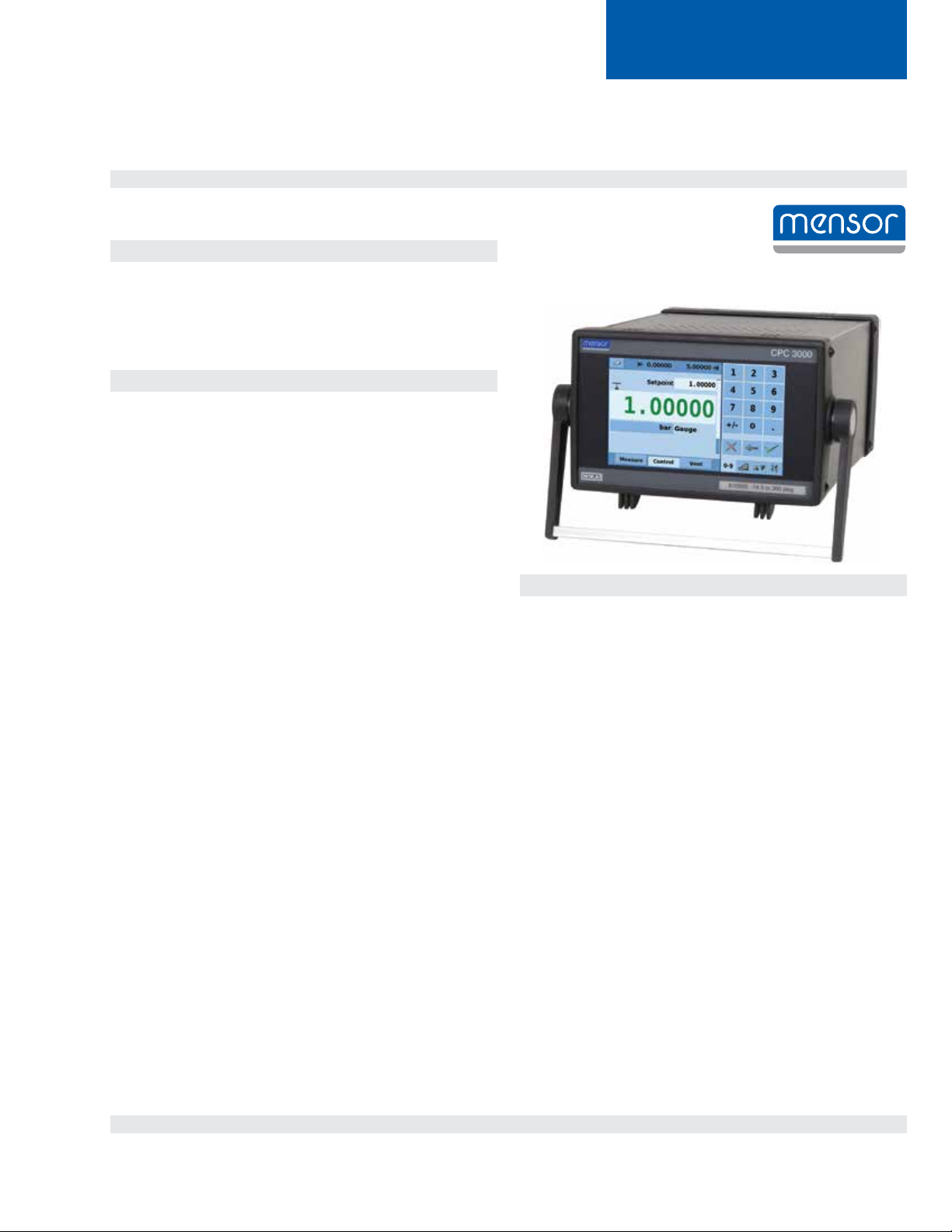
High-Speed Pneumatic Pressure Controller Model CPC3000
Data Sheet CPC3000 • 02/2014
Description
Overview
The CPC3000 has a compact, light weight design, a reliable
high speed pressure regulator, gauge / absolute / bi-directional
ranges and an optional barometric reference for emulation. These
qualities make the CPC3000 suitable for a variety of applications.
Applications
With an uncertainty of 0.025% FS and a high speed regulator,
the CPC3000 is well suited for use in the production of pressure
sensors, transmitters, transducers, and pressure switches or as
a working standard for the control and calibration of all types of
pressure gauges.
Functionality
A color touch-screen, combined with user-friendly menus, guarantees high productivity in a calibration lab or production facility; all
screens can be viewed in several dierent languages.
To enter the pressure setpoint, the operator can choose between
four input modes which can be selected using the corresponding
tab. The input modes are:
1. The numeric key menu provides a way to enter a specic
pressure set point value to be controlled.
2. The step keypad menu provides dened steps programmed
in pressure increments or percent of a user dened span to
move the pressure setpoint across the range of the instrument under test.
3. The jog key menu provides a way for the operator to dene
small pressure steps up or down to reach a cardinal point on
a dial gauge. The jog buttons increment the least signicant
digit by 1, 10 or 100 counts.
4. The user dened Jog menu provides a way for the operator
to dene any step within the span to increase or decrease
the setpoint.
Software
Customers can create their own test programs using the Mensor
communication command set, the SCPI command set or the
emulation command set used when replacing other calibrators.
Complete testing and calibration systems
Communication with other instruments is made easy with an
IEEE-488.2, an Ethernet and a USB interface. The CPC3000
can be integrated into an existing system, or our Custom Systems
group can design a system to meet a specic need.
Page 1 of 8Data Sheet CPC3000 • 02/2014
Page 2
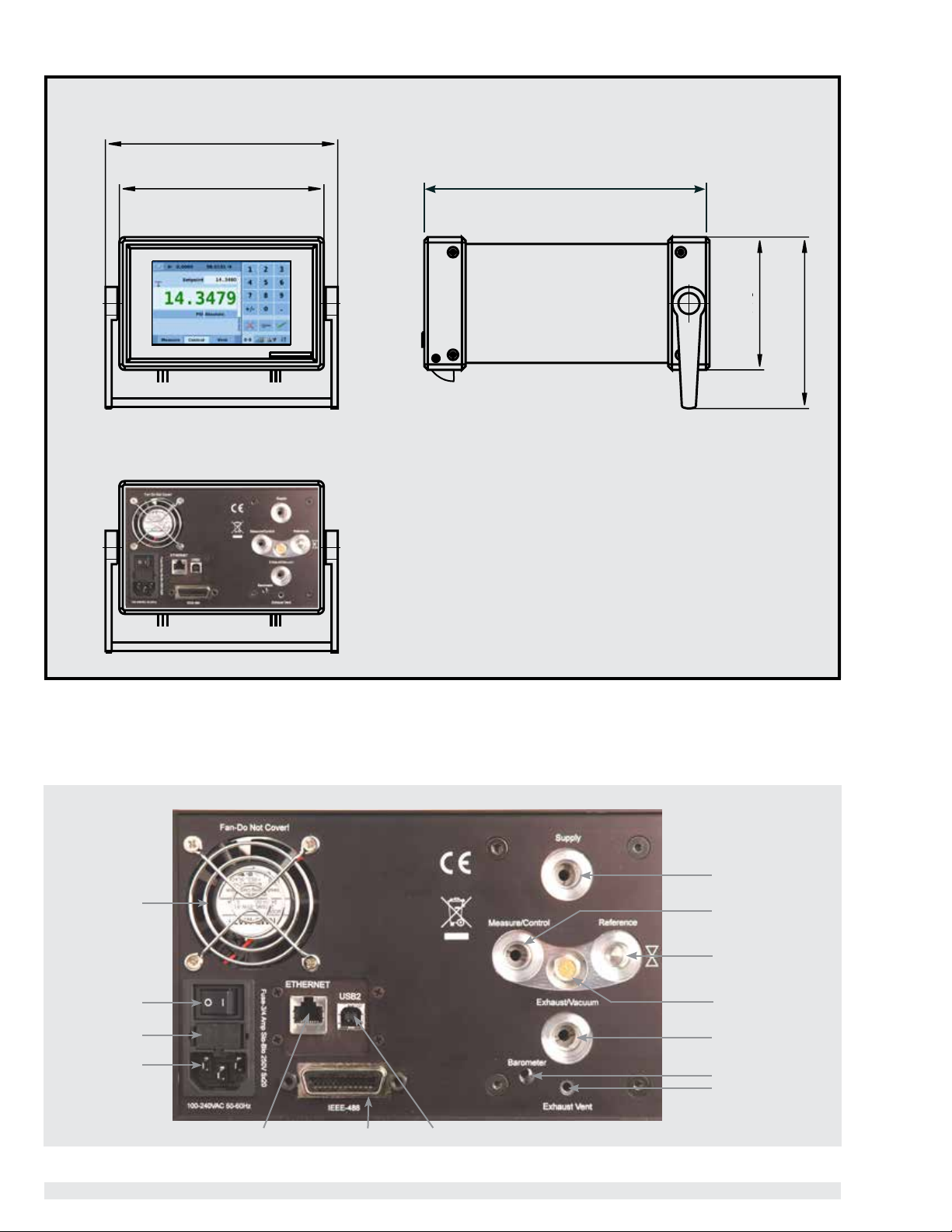
Dimensions in inches
Front view Side view
10.1875
Rear view
8.6875
12.3125
5.5
7.375
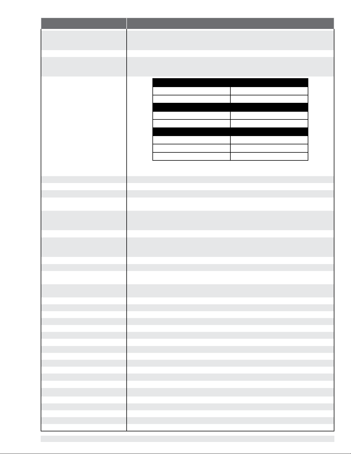
Electrical connections and pressure ports - rear view
Supply
Fan
On/O switch
Fuse
Power supply
Ethernet IEEE-488 USB
Page 2 of 8 Data Sheet CPC3000
Measure / Control
Sensor Ref. Port
Vent
Exhaust/Vacuum
Barometer Port
Exhaust Relief Port
Page 3
Specications CPC 3000
Pressure ranges Gauge: 0 ... 5 up to 0 ... 1500 psig (0 ... 0.35 to 0 ... 103 bar)
Absolute: 0 ... 14.5 to 0 ... 1515 psia (0 ... 1 to 0 ... 104 bar)
Bi-directional: 5 ≤ span ≤ 1515
Pressure types Absolute, gauge or bi-directional ranges
Uncertainty 0.025% full span for all standard pressure ranges specied above. Uncertainty (k=2) includes
hysteresis, linearity, repeatability, reference standard, drift and temperature eects over the calibrated
range for the calibration interval specied, with periodic re-zeroing.
Gauge
Transducer Range (psig) Total Uncertainty
0 ... 14.5 to 0 ... 1500 0.025% IS-50
Absolute
Transducer Range (psia) Total Uncertainty
Optional Intelliscale Uncertainty
0 ... 14.5 to 0 ... 1515 0.025% IS-50
Bi-directional
Transducer Range (psi) Total Uncertainty
-15 ... 145 to -15 ... 1500 0.025% IS-50
5 ≤ span < 145
0.025% of Full Span (365 days)
(1) 0.025% IntelliScale-50 (0.025% IS-50): Uncertainty from Min to 50% of Max = (0.025% x 50%
x Max) or 0.025% of Reading from 50% to 100% of Max.
Optional barometer uncertainty 0.02% R from 8.5 to 17 psia for 365 days
Compensated temperature range
Calibration interval
15 to 45
days
365
°C
Pressure units: English psi, psf, oz/si, tons/sq in, tons/sq ft, atm, inHg @0C, inHg @60F, mTorr, Torr, inSW, ftSW, inH2O @4C,
inH2O @20C, inH2O @60F, ftH2O @4C, ftH2O @20C, ftH2O @60F
Pressure units: Metric mbar, bar, g/sq cm,
kg/sq cm, dyn/sq cm, pascal, hPa, kPa, MPa,
mmHg @0C, cmHg @0C, mHg 0C, mSW, mmH2O @4C, cmH2O @4C, mH2O @4C, mmH2O @20C,
cmH2O @20C, mH2O @20C
Pressure units user dened
2 (multiplier from psi or Pascal)
Slew rate 3 seconds to stable ag (+/-0.025% full scale pressure) for a 10% pressure change typical into
150cc volume at pressures greater than 5 PSI. Larger volumes can lengthen this time. Controlling to
pressures less than atmosphere can lengthen this time.
Overshoot
<1
% FS, in high speed mode
Control stability 0.003% of range
Pressure ports 7/16-20 Female SAE threaded ports for Measure/Control, Exhaust, Reference, and Supply.
Barometric Reference port is a hose barb.
Filter elements 40 micron lter element included in each pressure port (excluding the optional barometer and the
reference port on a gauge sensor)
Permissible pressure media Clean, dry, non-corrosive gases
Parts exposed to pressure media 6000 series aluminum, 316 SS, brass, Teon, Urethane, Silicone, RTV, Silicone grease, PVC, Epoxy, Ceramics
Overpressure protection Pressure relief valves
Instrument mounting Desk top with bezel and handle, or optional rack mount kit.
Display 7.0" color LCD
Resolution Six signicant digits
Warm-up time
approx. 15
min
Digital interface IEEE-488, Ethernet, USB
Power supply 100 - 240 VAC, 50/60 Hz, 700 mA max
Maximum pressure, supply port 110 … 120 %FS
Pneumatic overpressure protection internal relief valves
Operating temperature
Storage temperature
Air humidity
0 … 50
°C
°C
0 ... 70
0 … 95 (% relative humidity without moisture condensation)
Operating position Negligible, can be removed with re-zeroing
Weight <20 lbs.(<9.1 kg) with all internal options
Dimensions 5¼ h x 8⅜ w x 12 d in (133 x 213 x 305 mm)
CE-mark Conformity certicate
Calibration NIST traceable calibration certicate included, A2LA certication
(1)
(cal interval)
(1)
(365 days)
(1)
(cal interval)
(1)
(365 days)
(1)
(cal interval)
(1)
(365 days)
Data Sheet CPC3000
Page 3 of 8
Page 4

Touch screen operation
Main screen
The CPC3000 main operation screen appears after powering up the unit. This screen contains all of the controls needed to
navigate within the menus and to operate the instrument. The setup icon button opens up a menu that provides navigation to all
the set up screens, limits indication, tab selectable input menu, set point display and selection, pressure value indication, pressure
units indication and selection and measure / control / vent mode selection.
User dened DUT / control range limits
(congurable via SETUP)
Setup Icon Button
Entered set point
Stable indication
Current pressure value
Pressure unit and mode
Bar graph
Mode
MEASURE
Measure mode pneumatically connects
the pressure sensor directly to the device
under test. In measure mode pressure
regulation is inactive.
CONTROL
In the control mode, the device
regulates the pressure output
according to the set point value,
providing a precise pressure at
VENT
Vent mode vents the system and the
device under test to atmospheric
pressure.
Numeric keypad
Delete selected set point
Delete last entered digit
Accept selected set point
the test port.
Optional information can be displayed in the main menu by selecting the option in the setup menu
Communication status*
* optional display element
Page 4 of 8
SETUP
menu
Optional barometric reference display*
SETUP menu
The SETUP menu allows conguration
of the following points:
Language (17 currently available)
Maximum control range
Step and Jog functions
Interface setting
Display of additional information
Jog key pad selection tab
User dened Jog
Step key pad selection tab
Numeric key pad selection tab
Note: See the following page for detailed information on
each set point entry screen.
Data Sheet CPC3000
Page 5

The pressure set point can be changed using one of three input modes
The numeric keypad
Application: Direct input of set point value.
Operation
The desired pressure set point value is entered using the numeric
keypad and then acknowledged by pressing the check mark key.
In control mode the controller will regulate the output pressure to
Delete input, delete last character,
input acknowledgement
Numeric keypad
The step keypad
Application: Calibration of incremental user dened pressure points or percent of full span of the device under test.
Congurable via SETUP
% of span of limit value
User dened pressure steps
the entered value.
Operation
Each step on the step keypad can indicate user dened pressure
values or percent of span values for the device under test. For
example: the step keypad shown to the left is set for 10% steps
going from 0% to 100%. These steps are a percent of the user
dened device under test full span. In control mode, when a step
is touched, the controller will regulate the output to the associated set point.
Step keypad
The jog keypad
Application: Fine adjustment of the pressure value to reach a cardinal value on a pressure gauge or similar device under test.
Set point
increased
by:
Least signicant digit x 100
Least signicant digit x 10
Least signicant digit
Operation
The triangles on the Jog keypad have values which correspond
to the 3 last digits of the pressure reading and are used to increment the set point. Triangles pointing up will increase the value
and those pointing down will decrease it. The smallest triangle
Set point
decreased
by:
Least signicant digit
Least signicant digit x 10
Least signicant digit x 100
increments the least signicant digit by one, the medium size
triangle increments the least signicant digit by ten and The large
triangle increments the least signicant digit by one hundred. The
values will change accordingly if the resolution of the indication
is changed.
Jog keypad
The user dened jog keypad
Application: User dened quick pressure adjustment.
Operation
Increase by user dened amount.
User dened amount key.
Decrease by user dened amount.
Pressing the “User Dened Amount” key will open a numeric
entry screen where a user dened amount can be entered. This
value will be shown in the key indication. Pressing the triangles
will increase or decrease the set point by this value.
Data Sheet CPC3000
Page 5 of 8
Page 6

Application — Typical Setup
50
40
30
20
10
60
70
80
90
PSI
0
100
Clean, dry
pressure supply
Application — Setpoint entry options and function
Direct entry of setpoint using the numeric
keypad: enter the setpoint value and press
. The controller will then ramp up the
setpoint.
Setpoint entry using the step keypad:step
changes, automatically calculated as a
percent of the user dened full scale limit,
and indicated in percent FS or pressure
units can be entered by pressing step keys
(
) in any sequence.
Range : 0 ... 500 psig S/N: 811000
Percent of Setpoint
100
80
60
40
20
Device Under Test
100
80
60
40
20
0
Percent of Setpoint
0 1 2 3 4 5
Time (s)
0
Steps changed at operator discretion
Setpoint entry using jog keypads:
setpoint can be increased or decreased
in small or large steps using the jog
keys
to reach a cardinal point on
a dial gauge or step through a calibration sequence.
Page 6 of 8 Data Sheet CPC3000
100
50
150
250
200
0
PSI
300
350
400
450
500
Page 7

Communications
The variety of communications modes and command sets make the CPC3000 a good choice to replace older pressure controllers
that communicate remotely via IEEE-488. The Mensor command set will integrate seamlessly with other Mensor controllers and the
SCPI command set provides integration in areas where the SCPI command structure has been used. The CPC3000 even understands
commands and automation programs that have been written previously for non-Mensor / non-WIKA controllers. Within the setup
menu, under the remote tab, communication emulation selections are available to switch between the various command structures.
In addition to IEEE-488, the CPC3000 has Ethernet and USB communications making it remotely accessible to today’s modern
automation systems. Trouble shooting the initial remote setup is made easy by viewing the remote monitor which displays the most
recent commands sent and responses from the CPC3000 plus any error messages.
Options and accessories
Barometric reference
An optional barometric reference is available for emulation of gauge pressure when the internal sensor is absolute and emulation
of absolute pressure when the internal sensor is gauge. The internal gauge sensors must include a negative gauge range of one
atmosphere in order to be able to emulate sub atmospheric absolute pressures.
Rack mount kit
A 19” x 3U rack mounted tray is available.
Pressure adaptor ttings
Customized calibration systems
Page 7 of 8
Page 8

Scope of supply
CPC3000 High-Speed Pressure Controller
(Desk top version with bezel and handle)
Power cable (6 ft.) with plug
Operating instructions
NIST traceable calibration certicate
Pressure adaptor ttings
A2LA certicate
Options
Barometric reference
19" rack mounting kit
Customized calibration system
Accessories
Additional pressure adaptor ttings
All standard Mensor products are provided with a calibration
certificate traceable to NIST. The calibration program at
Mensor is accredited to both ISO/IEC 17025:2005 and
Z540-1-1994 by A2LA. Mensor is certied to ISO9001:2008.
©2007 Mensor.
Specications and dimensions given in this leaet represent the state of engineering at the time of printing.
Modications may take place and materials specied may be replaced by others without prior notice.
Page 8 of 8 Data Sheet CPC3000 • 02/2014
Represented by:
Mensor
201 Barnes Drive
San Marcos, Texas 78666
Toll Free: 800-984-4200
Tel: 512-396-4200
Fax: 512-396-1820
Email: sales@mensor.com
 Loading...