

Page 1
MENSOR MODEL 73 SHOP AIR BOOSTER
Operation Manual - PN 0017946001 A
®
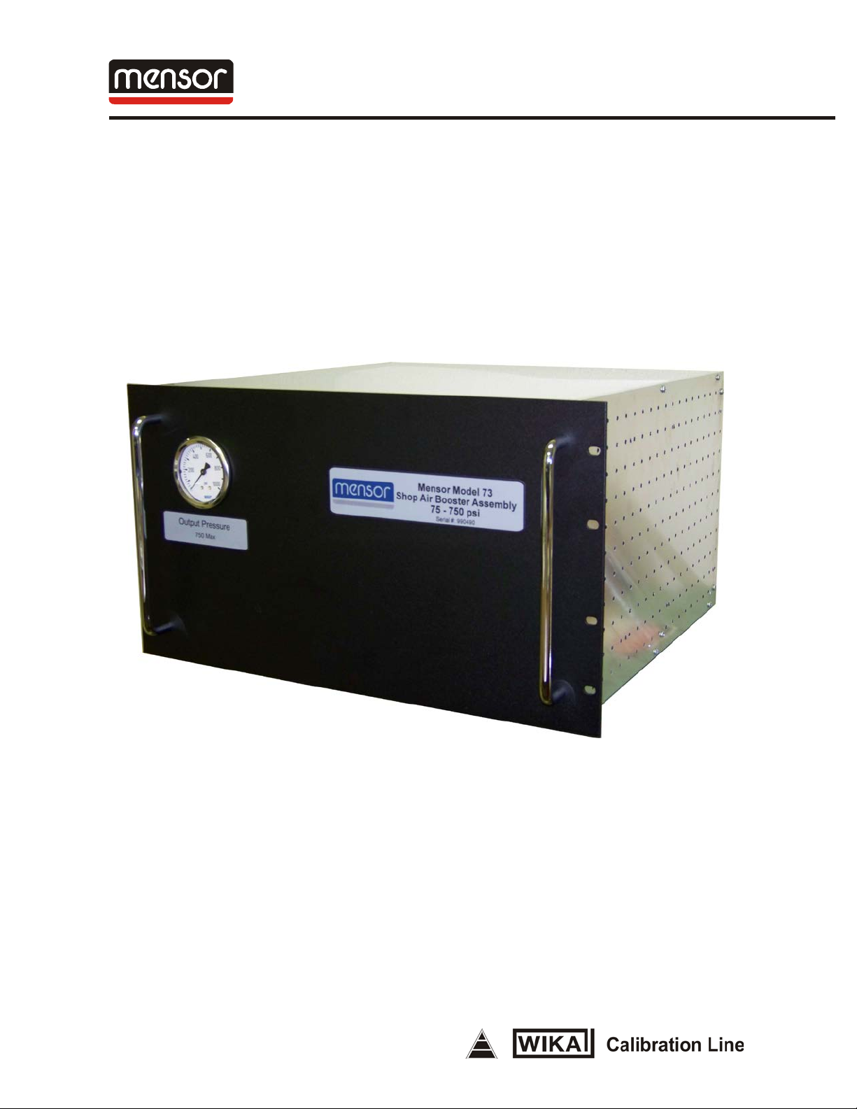
Mensor Model 73
Shop Air B o oste r Sy s tem
(750 psi Version)
April 23, 2012
Page 2

Trademarks / Copyright ©
Mensor is a registered trademark of Mensor Corporation. All other brand and product
nam es are tradema rks o r registe red trademarks of their respective compan ies.
© 2010 M ensor Co rpo rati on. All righ ts reserved.
Page 3

Operation Manual
Mensor Model 73
Shop Air Booster System
GENERAL INFORMATION
The Mensor Model 73 Shop Air P r essur e Booster generates 325 psi to 750 psi using a 70 psi
to 150 psi clean dry shop air source. The Model 73 co nsist s of a single 5 t o 1 pressur e boost
stage with limits for speed control and maximum output pressure control. To achieve the 325
psi output, a minimum supp ly of approximately 70 psi is required. To achieve 750 psi, a 150
psi supply is required. 150 psi is the maximum input pressure the unit shou ld be subjected to.
The unit is purely a mechanical de vice and has no electrical requirements.
WARNINGS AND SAFETY PRECAUTIONS
Caution: High Pressure Gas can be extremely dangerous if improperly
handled.
Caution: Unit should be operated, adjusted and maintained by qualified
personnel trained in high pressure pneumatics.
Caution: All Tubing, Fittings and connected devices must have a working
pressure rating equal to or greater than the maximum required
pressure.
Caution: All connections should be in good mechanical condition, i.e. good
threads on fittings, tubing free of kinks or nicks, etc.
Caution: All connections should be properly installed and tightened.
Caution: Small articles exposed to the escaping gas can be propelled at
ballistic speeds to the endangerment of nearby personnel and
equipment.
Caution: Under certain conditions the noise level created by gas exiting
equipment under high pressure can become dangerously high.
Caution: The maximum input pressure to the unit is 150 psi gauge pressure.
The input regulator and the input filter are rated for 150 psi
maximum.
INITIAL SETUP AND CHECKOUT
On initia l s etup, user should check to insure no shipp ing damage has occurred to the unit o r
the container it was shipped in. Prior to co nnect ing pr essur e, check a ll hoses for k inks and
nicks and insure fittings are snug. Verify that the regulato r filters are not cont aminated with
Page 4
liquid or particulates. User should verify input pressure (shop air) is within the operating
rang e of the boos ter and w ithin the r a nge of any test device connected prior to applying the
input pressure. Althoug h t he regulator pressure sett ings have been set at t he factory, the user
should on initial applic a tion verify the incoming shop air is 150 psi or less and the input
pressure gauge on the rear of the unit is approximately 50 psi or less. The black regulator
knob should be used to adjust the input pressure either increasing o r decr eas ing the o ut put
pressure as appro pr iate. The front panel gauge shows the actual output pressur e valu e. Once
the system is operational, t he black regulator knob should be used to set the final output
pressure t o mat ch t he app lication and the controller full scale. S ome f i n al a dju s tmen ts may b e
required to co mpensate for differences in actual sup ply pressure.
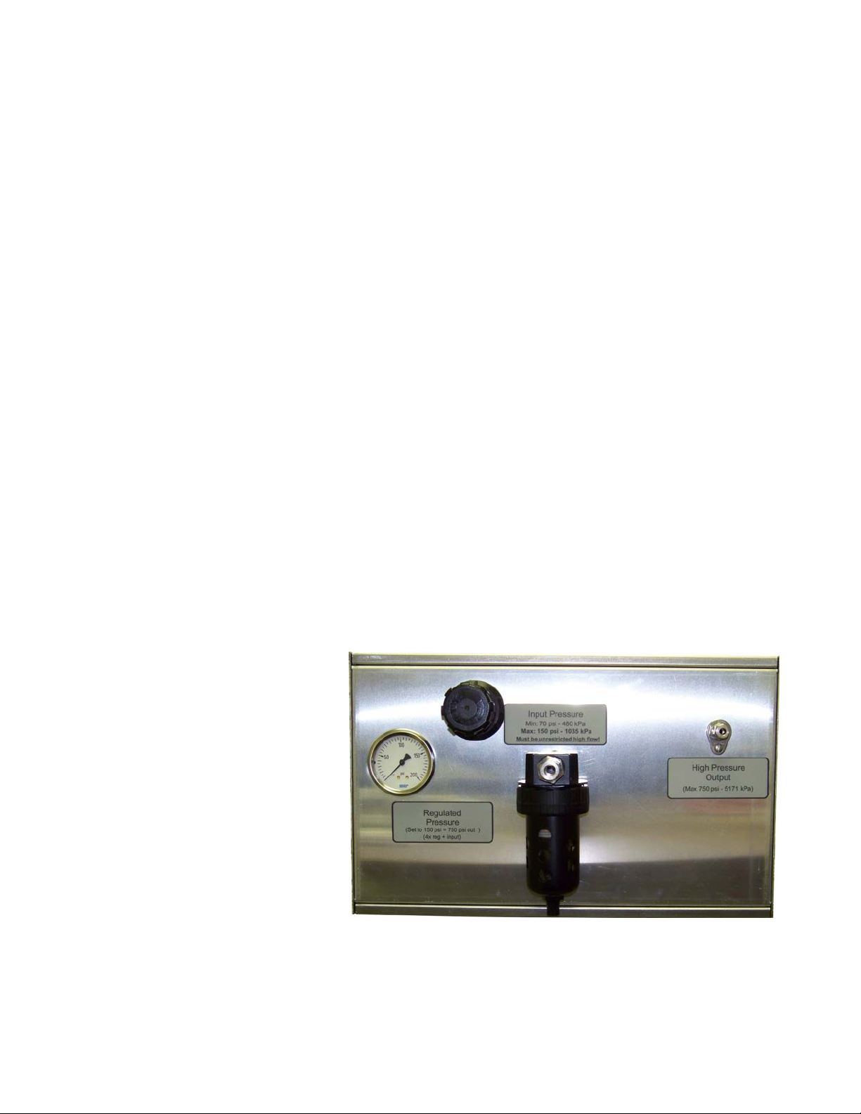
PORTS, CONTROLS AND ADJUSTMENTS
There are two pressure ports on the rear of the Model 73 chassis. The input pressure port is
designed for a shop air supp ly which functions as the drive pressure as w ell as the output
media. It should be clean dry co mpressed air (or Nitrogen) at a pressure of 70 to 150 ps i.
(Abso lut e Max i mum Input Pressure is 150 psi to the rear mounted pressur e filter.) This
pressure is regulated dow n to a typical working pressure of 50 to 150 psi. The second
pressure port is the HIGH PRESSURE OUTPUT port. It is desig ned for a typical output
pressure of 325 to 750 psi. The mechanical ad vantage is derived by using differing piston
area sizes to generate high pressures. T he output eq uation is :
Output Pressure = I nput Pressure + ( Regulated Pressure * 4)
The i nput port is a 3/8” Swagelok male type tube fitting mounted on the external pressure
filter. T he Output port is a ¼” Swagelok male type tube fitting.
Input Pressur e Port
The input pressure port labeled
“INPUT PRESSURE” is used to
supply and drive the boo s ter a nd
is intended to be connected to a
shop air supply of 70 to 150 psi
(150 psi m ax ). The port is a 3/8”
male Swagelok type tube fitting
mou nted on t he end of a pressure
filter. A 200 psi rear mounted
panel gauge provides an
indication of the regulated shop
air pressure input. If shop air is
not present on the gauge the user
should check to see if the shop
air is present on the input port
and the r e gulator knob is no t fully countercloc kwise. The input regulator filter provides basic
filt ering of la rge p a rt ic le s and liquids. It shou ld periodical ly be checked for excessive
co ntamin ation a nd e mptied of liquids . Note: The input pressure supply should have
Page 5

sufficient capacity (flow) to maintain the input pressure setting. Failure to do so may
Rear V iew
cause the booster to short cycle and not be able to achieve t he desired output press ure. If
external regulators are in line with the shop air supply, make sure that t hey do not restr ict the
input flow. Also use large diameter supply hoses (3/8” or larger) is recommended.
High Pressu r e Output Port
The output pressure port is a ¼” male Swage lok type tube fitting. The actual output pressure
can be monitored with t he pressure gau ge located on the front panel. The output pressur e is a
combination of the raw input supply pressure plus four t imes the regulated pressure as read on
the Regulator Pr essur e gaug e. It can be adjusted wit h t he black Regulat or Adjustment Knob.
OPERATION
While operation of the booster system is quite simple, high pressure gas is da ngerous.
NOTE: Operation of this unit and maintenance of this unit should be performed by
qualified personnel only.
1. Connect a low pressure supp ly such as shop air to the “INPUT PRESSURE” port.
The system req uire s a minimum o f 60 psi to obtain 300 psi output.
2. Connect the load (pressure con trol ler) to the ‘ HIGH P RE SS URE OUTPUT ” p ort .
Be careful to use tubing rat ed for the boo st ed wo r king pressure.
3. Slowly apply shop air to t he “INPUT PRESSURE” port while monitoring the
“OUTPUT PRESSU RE ” gaug e on the front of the unit.
For most applicat ions, t he boo st er
piston temperatures will not be a
problem. However, if a part icular
application causes t he booster piston
to operate frequently, the high
pressure end of the booster cylinder
may overheat. Temperatu r es in the
cylinder above 300 degrees F will
co nsiderably shorten t he life of the
piston seal. Temperatu r es can be
minimized by reducing the drive
speed while still maintaining the output pressure, but at a slower r echarge r ate. T he drive
speed is adjusted by re moving the top cover and adjusting the yellow ball valve lever. The
unit is shipped with this lever in the wide open position. Experience has s hown, tha t under
all but the most extreme condit ions, temperature prob lems shou ld be of no concern.
DISCONTINUE OPERATION
To discontinue operation of the booster system:
Page 6

1. Valve off any pre ssure going to the “INPUT PRESSURE” port. Disconnect the
supply gas if desired. Alternately, the Regulat o r Pressure knob can be adjusted until
the regulator pressure r eads zer o.
2. Wit h the input p r e ssu r e shut off, slo wly v ent the out put pressure by cracking the
output connector to let t he pressure slowly release or by continually cycling the
controller between an accept ab le co nt r ol pressure and vent until pressure is dra ined.
Mainta in a saf e noise leve l whe n venting. Wait until the output gauge reads 0 psi
before disconnecting the controller or load.
TROUBLESHOOTING
This section prov ides simple op er ational checks. The Haskel AAD-5 ma nua l att ached
contains additional information.
If the unit does not pump…
1. Verify that the “INPUT PRESSURE” has pressure applied.
2. Verify that the r egulato r pr essure knob is slightly ope n and the Regulator Pressure
gauge reads approximately 50 to 150 psi (just not at zero).
If t he unit continu ally cycles after reaching pressure and the temperature of the gas has
stabilized or when cycling occurs when not being used….
1. Check for leaks in the syste m. Use a leak detector to tr ack down a nd corr e ct the
problem.
MAINTENANCE
NOTE: High Pressure Gas can be dangerous. Maintenance of this unit
should be performed by fully qualified personnel only.
Booster Unit:
The control valve and the pilot valves on the Haskel Booster may o ccas io na ll y need relubrica tion on units e xperiencing a high a mount of us e. Instr uctio ns and a s pec ial lubrica nt
are provided in the Haskel manuals in the Appendix.
Drive Pressure Filters
Each booster is equipped wit h a filter a nd regulator. The filters should be inspect ed o n a
regular basis. Dra in any accumulat ed moisture or sludge throu gh the dra in petcock on the base
of the filter.
Occasionally, clean t he interna l filter element inside the filter sed iment bo wl. To access the
element, first discon nect all pressures from the system. Unscrew the filter bowl ring nut by
hand and r emove the bow l and filter element screw.
Page 7

Clean t he bowl with either s oap y wate r or keros ene. Clean the ele ment with a cleaning
solvent. Dry all the parts and reasse mble. Make sure that the o-r ing sea l fo r the bowl is
properly po sitioned , re place the bow l and tighten t he ring nut by hand.
The Haskel recommended maintena nce schedule is listed in the append ix.
Page 8

High Pressure
Front View
Regulator Adjust
Regulator Gauge
Input Pressure
Section)
High Pressure
Moisture Trap
Speed Adjust Lever
Input Pressure Port
Rear View
Output Gauge
(50 to 150 psi)
Filter (See
Maintenance
Output Port
(750 PSI Max.)
150 psi Max.
Releas e Valve
(located insi d e chassis)
Page 9

SPECIFICATIONS
Input Pressure:
Dry Compressed air or Nitr ogen at a maximum of 150 PSI (1.03 MPa)
Output Pressure:
Comp ressed air or Nitrogen up to 750 psi with appro priate supply pressure
Not to exceed 750 psi maximum.
Charge Noise Level:
Approximately 80 dbA intermittent pulses measured at 1 meter
Weight:
45 lbs or 20.4 kg
Size:
Rack Mounted 7U Chas sis,
19” wide, 10.5” tall, 17.25” deep (482.6 mm x 266.7 mm x 438.15 mm)
(User accessib le filter extends depth by an additiona l 5” or 127 mm in the rear.)
Page 10

APPENDIX
Hask el Opera ting and M aint ena nce I nstructions
Page 11

Mensor Corporation
201 Barnes Drive
San Marcos, Texas 78666-5994
Phone: 512.396.4200
Fax: 512.396.1820
Web site: www.mensor.com
E-mail: sales@mensor.com
 Loading...