

Mennekes Electrical Products Plugs Connectors Receptacles & Inlets Wiring Instructions
MENNEKES WIRING INSTRUCTIONS
60A & 100A PowerTop Xtra
Plugs, Connectors, Receptacles & Inlets
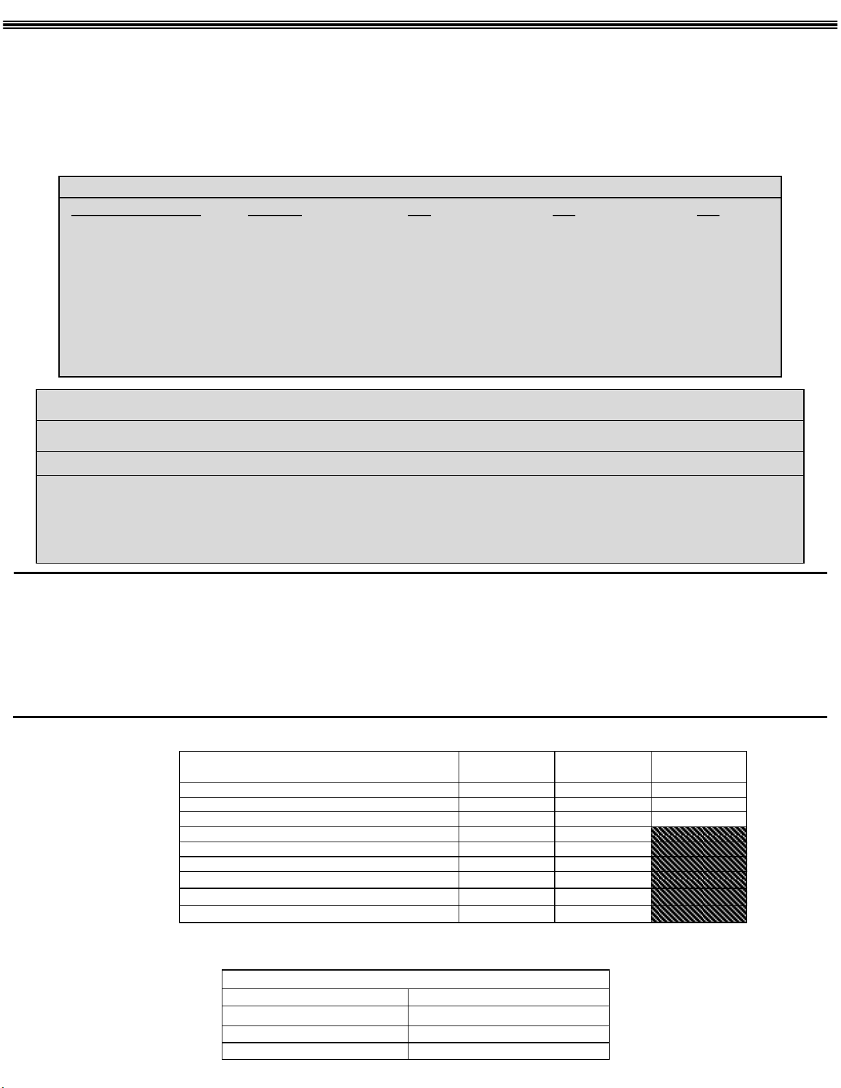
Color Coding: All device are color coded to easily identify voltage
GROUND SLEEVE POSITION
RATED VOLTAGE
110V–125V
220V- 250V
440V– 480V
600V
277V
125/250V
415V
ME 4 60 R 7 W
COLOR
Yellow
Blue
Red
Black
Gray
Orange
Red
3W
4
6
7
-
5
-
-
CATALOG NUMBERING SYSTEM
4W
9
7
5
-
12
6
5W
9
7
5
-
6
Mennekes PIN CONFIGURATION AMPERAGE DEVICE TYPE POLARIZATION ENVIRONMENTAL RATING
3-2 POLE + E
4-3 POLE + E
5-3 POLE + N + E
60 100 P-PLUG
C-CONNECTOR
R-RECEPTACLE
B-INLET
CLOCK POSITION OF
FEMALE SLEEVE
(MALE PIN
CORRESPONDS TO
RESPECTED
FEMALE POSITION)
W-WATERTIGHT
(SCREW CAP &
LOCKING RING)
WARNING: BE SURE THE POWER IS OFF BEFORE STARTING INSTALLATION.
READ ENTIRE DIRECTIONS BEFORE STARTING INSTALLATION.
Caution: Check to see that the rating label on the device is correct for the installation.
Select cable/conductor of suitable ampacity, service and temperature. See TABLE I per NEC Article 400.
Notes: Watertight versions have locking rings and locking covers, weatherproof versions do not.
60 Amp and 100 Amp devices do not require use of wire ferrules.
The Following Tables are Referenced in Wiring Instructions for all Devices:
TABLE l
Wire Capacity
Terminal Torque IN-lb
Strip length jacket
Strip length conductor (“hot”, neutral)
Strip length ground 0.60” (conn/recep)
Cord Capacity Round 3W; 4W; 5W:
Strain Relief Nut (4) Torque in lb.
Cable Clamp Screw (11) Torque in lb.
Trade Size Thread of Housing (NPT) 3W; 4W; 5W:
60Amp 100Amp Pilot Contact
#8 to #4 #2 to #1/0 14 AWG
18* 88.5* 7 in/lb.
3.15” 4.33” 3/10”
0.67” 1.06”
0.67” 1.06”
.60 to 1.45 .96 – 1.92
66 66
18 35
1 1/2” 2”
*Each terminal should be torqued at full recommended value for 2 complete cycles: Tighten both screws of each terminal for one
cycle and repeat the process again. 100A = #5 allen headscrew.
TABLE II
TERMINAL IDENTIFICATION USE
G, ⏚ or Green
W, White System ground (neutral conductor)
L1, L2, L3 or X, Y, Z Line (“hot” conductors)
Equipment grounding conductor
PLUGS / CONNECTORS
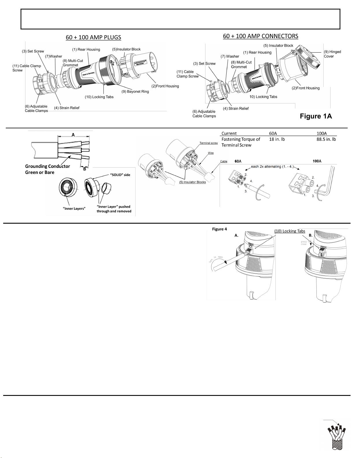
Figure 1 Figure 1A
Figure 2
For Copper
Figure 3
#5 Allen Head screw
Conductors ONLY!
1. Choose the correct end of the cable for plug or connector so that conductor
color coding corresponds to terminal location.
2. Disassemble device as shown in Figure 1A by unscrewing the rear housing (1)
from the front housing (2), loosening set screw (3) and unscrewing strain relief
(4). Do not attempt to disassemble the insulator block from the front housing.
Note – If locking tab (10) is in “Closed’ position, open as shown in Figure 4.
3. Strip the cable jacket and individual conductors per TABLE I. As seen in Figure
2, select cable/conductor of suitable ampacity, service type and temperature.
4. Slide strain relief (4) with adjustable cable clamps (6) and washer (7) over
prepared cable.
5. Remove "inner layers" from multi-cut grommet (8) until it slips over power
cable. Be sure not to remove any more than necessary. Remove one layer at a
time, by pushing through to solid side and tearing off. See Figure 2.
6. Slide cable through threaded opening of rear housing (1).
CAUTION Apply the next steps with care. Otherwise the device terminations and/or the cable grip will not be correct.
Risk of serious/fatal injuries due to electrocution could occur if steps are not completed properly.
7. Insert wires into proper terminals of insulator block according to the established wiring pattern. See TABLE II. Conductors must
bottom in contact terminal well. When stripped according to TABLE I, the uninsulated conductor will remain below the surface of
insulator block (within the metal terminal cavity). Tighten terminal pressure screws to the torque value listed in TABLE I. See Figure 3.
8. Thread rear housing (1) into front housing and align locking tab (10) with receiving piece on front housing (2). Press Close tab (10) as
arrow directs to secure rear and front housing together. See Figure 4A.
9. Slide multi-cut grommet (8) and washer (7) into threaded entry of rear housing (1) Screw strain relief (4) into rear housing (1) and
torque per TABLE I. The torque value is also located on the strain relief (4). Secure set screw in place so strain relief cannot turn.
10. Tighten cable clamp screws (11) around power cable to the torque in TABLE I. Alternate tightening sequence from side to side as
needed to prevent binding.
NOTES:
1. The devices will work with Hard Service, Junior Hard Service and Portable Power cable/cord per NEC 400 5(A)(1) or Canadian
Electrical Code Table 12.
2. The respected cord diameter must be within the range specified in TABLE I.
3. The conductor size of the cord must be within the range specified in TABLE I.
4. The cable opening of the rear housings are NPT threaded. A UL Listed trade
fitting with compatible threading can be utilized in place of the provided external strain relief fitting.
One ungrounded conductor
over grounded conductor
 Loading...