

Menlo Systems FPD610-FC-VIS, FPD610-FC-NIR, FPD610-FS-VIS, FPD610-FS-NIR, FPD310 Series User Manual
...Page 1
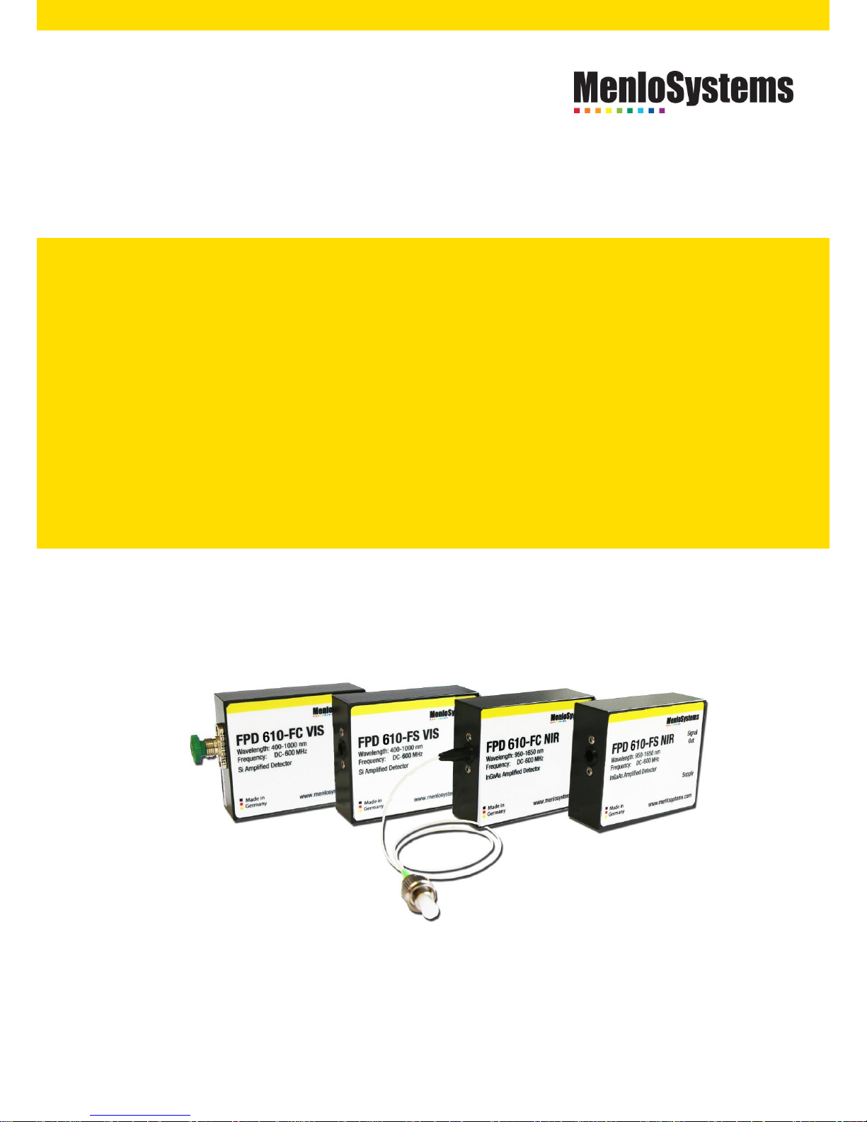
FPD610-Series
High Sensitivity Fast PIN
Photodetector
USER MANUAL
Page 2

2
Excitement Is Not Measureable. Light Is.
Menlo Systems, a leading developer and global supplier of instrumentation
for high-precision metrology, was founded 2001 as spin-off of the MaxPlanck-Institute of Quantum Optics. Known for the Nobel-Prize-winning
Optical Frequency Comb technology, the Munich based company offers
complete solutions based on ultrafast lasers, synchronization electronics
and THz systems for applications in industry and research.
Page 3

3
A. IMPRINT
Title: User Manual
Model: FPD610-FS-VIS, FPD610-FC-VIS,
FPD610-FS-NIR, FPD610-FC-NIR
Manufacturer: Menlo Systems GmbH, Munich, Germany
Copyright: © 2017 Menlo Systems GmbH. All rights reserved.
Reproduction by any means of any image in this user
manual is prohibited without the prior consent of Menlo
Systems GmbH.
All product designations used in this manual are registered
trademarks of the respective companies.
Changes: Subject to technical changes without prior notice.
Page 4

4
B. TABLE OF CONTENTS
A. IMPRINT ................................................................................................................................................ 3
B. TABLE OF CONTENTS ............................................................................................................................ 4
1. SAFETY INSTRUCTIONS ......................................................................................................................... 5
I.1 Electrical Safety Precautions......................................................................................................... 5
2. System Overview .................................................................................................................................. 6
Contents ....................................................................................................................................... 6 2.1
Connectors and Controls ............................................................................................................. 7 2.2
Specifications ............................................................................................................................... 8 2.3
2.3.1 Response Curve ...................................................................................................................... 9
2.3.2 Frequency Characteristics ...................................................................................................... 9
2.3.3 Time Characteristics and Rise Time ..................................................................................... 10
Technical Drawings .................................................................................................................... 11 2.4
3. Installation / Operation ...................................................................................................................... 13
4. Maintenance ....................................................................................................................................... 14
5. Troubleshooting .................................................................................................................................. 15
C. Customer Service ................................................................................................................................ 16
C.1 Factory Service & Repair ............................................................................................................ 16
C.2 Additional Service Plan .............................................................................................................. 16
D. Regulatory ........................................................................................................................................... 17
D.1 Waste Treatment is Your Own Responsibility ........................................................................... 17
D.2 Ecological Background ............................................................................................................... 17
E. Contacts .............................................................................................................................................. 18
Page 5

5
1. SAFETY INSTRUCTIONS
I.1 ELECTRICAL SAFETY PRECAUTIONS
You should make sure that electrical equipment used for work is safe. Here is a list of
actions that should be taken:
Do not use wet hands when turning on electrical equipment.
Check that the electrical equipment is suitable for the work and way in
which it is going to be used.
Check that the electrical equipment is in good condition.
Check that the equipment is suitable for the electrical supply with which it
is going to be used, and the electrical supply is safe.
Make sure that the user of the equipment is trained to use it safely and can
keep others safe.
Make sure the user knows which personal protective equipment to wear,
how to use it, and make sure they do so.
Power failures should be avoided.
Page 6
6
2. SYSTEM OVERVIEW
2.1 CONTENTS
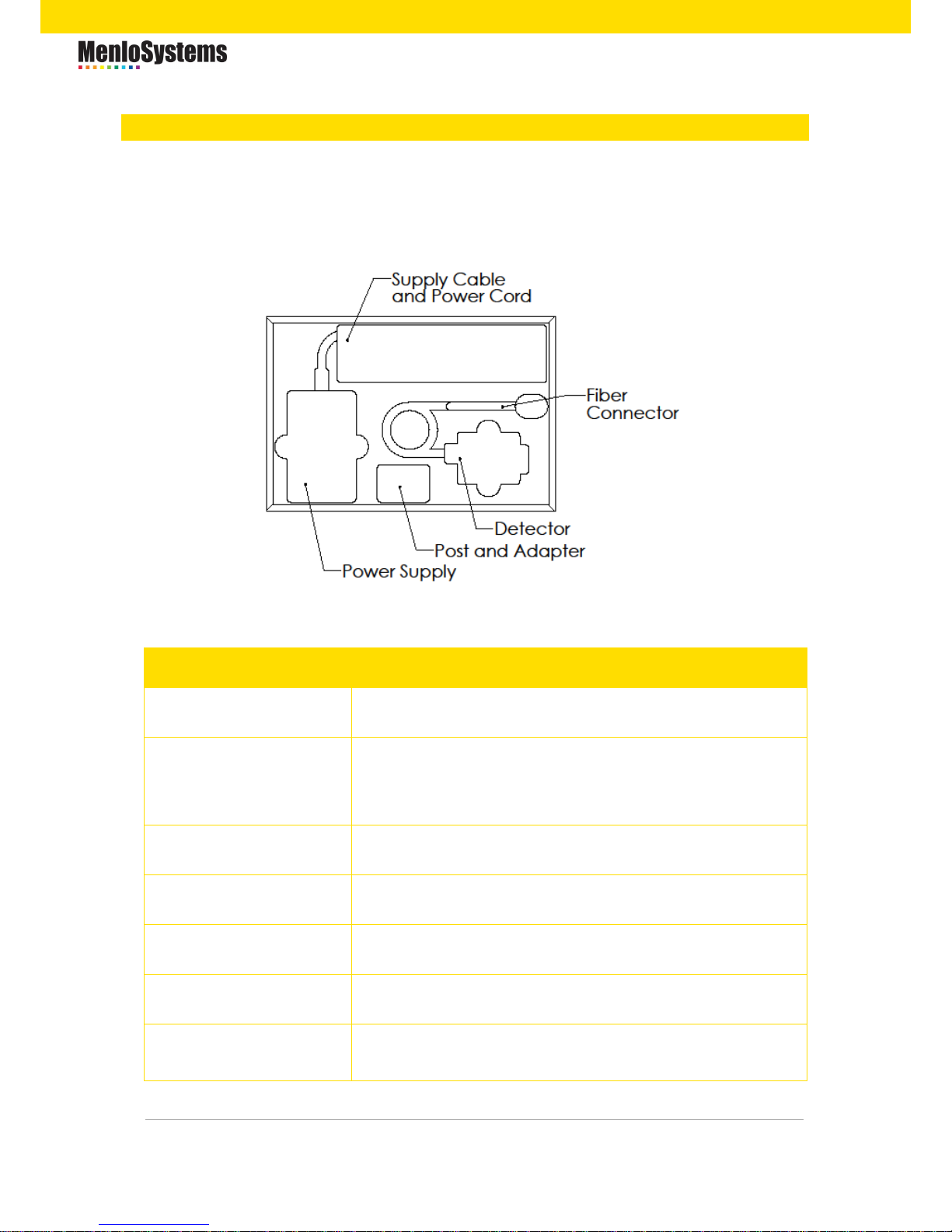
Your photo detector case contains the following items:
Item
Description
FPD photodetector
Photodetector FPD610
Adapter
Adapter for imperial threads
(Internal 8-32 threads and external M4 x 0.7 threaded
stud)
Post
40 mm post with M4 setscrew and M6 tap
Power Supply
Low noise power supply (Voltage +5V, -12V, GND)
Power Cord
Power cord suitable for your country
Manual
FPD Manual
Testreport
Final Test Measurement
Page 7
7
2.2 CONNECTORS AND CONTROLS
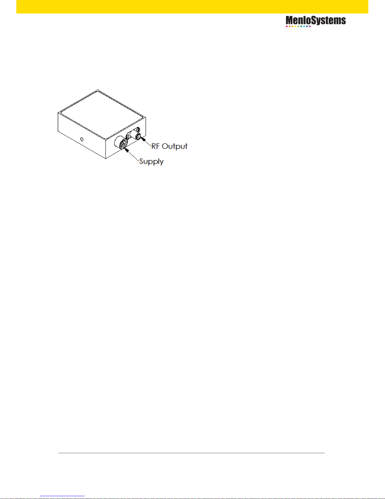
The detector itself has two connectors on the opposite side of the optical input:
RF Ouput: SMA female connector
Supply: multi-contacts Fischer receptacle
Connect the RF Output to a 50 Ω coupled measurement tool (e.g. oscilloscope, RF
spectrum analyzer,…) via SMA cable.
Connect the low voltage cable of the provided power supply to the Supply receptacle
and plug the power cord into the 100-230 V, 50-60 Hz outlet.
Each unit's housing features an M4 x 0.7 mounting hole (an adapter for imperial
mounting is enclosed) that enables the amplified photodetector to be vertically post
mounted (a 40 mm post is enclosed). For more information about the location of the
mounting point, please see chapter 2.4 Technical Drawings.
Page 8

8
2.3 SPECIFICATIONS
Specifications FPD610
-FC-VIS
-FS-VIS
-FC-NIR
-FS-NIR
Detector Type
Si
Si
InGaAs
InGaAs
Optical Input
Fiber:
FC/PC
connector
Free space
Fiber:
SMF28
pigtail with
FC/APC
Free space
Spectral Range [nm]
400-1000
400-1000
950-1650
950-1650
Saturation Limit [µW]
<100
<100
<100
<100
Damage Threshold [mW]
3 3 3
3
Detector Diameter [mm]
0.25
0.4 - 0.08
Freuency Range [MHz]
DC-600
DC-600
DC-600
DC-600
3dB Bandwidth [MHz]
DC-500
DC-500
DC-500
DC-500
Rise Time [ns]
1 1 1
1
Max. Gain [V
Peak-Peak/WInput
]
2 x 10⁶
2 x 10⁶
2 x 10
6
2 x 10⁶
Dark State Noise Level
not integrated
(up to 5MHz / 5-600MHz) [dBm]
-80 / -100
-80 / -100
-80 / -100
-80 / -100
NEP (calculated) [pW/√Hz]
11.9
11.2
5.6
6.6
Output Impedance [Ω]
50
50
50
50
Output Coupling
DC
DC
DC
DC
Output Signal [V]
0-1
0-1
0-1
0-1
Output Connector
SMA
SMA
SMA
SMA
Supply Voltage [V DC]
5
-12 5 -12 5 -12 5 -12
Max. Current Consumption [mA]
<250
<50
<250
<50
<250
<50
<250
<50
Operating Temperature [°C]
10-40
10-40
10-40
10-40
Storage Temperature [°C]
-20 - +85
-20 - +85
-20 - +85
-20 - +85
Storage Humidity [% RH]
10-90
10-90
10-90
10-90
Device Dimensions [mm³]
60x50x20
60x50x20
60x50x20
60x50x20
Page 9
9
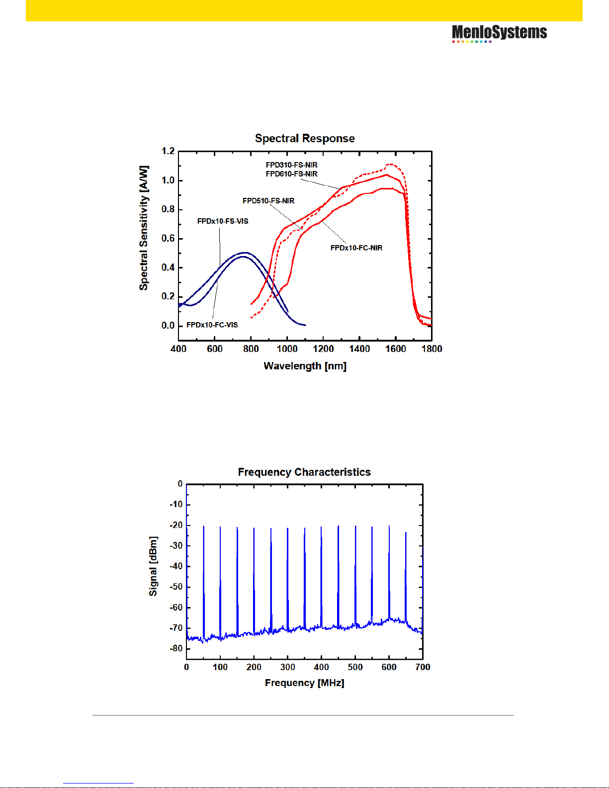
2.3.1 RESPONSE CURVE
The response curve for all models of the FPD series is shown below.
2.3.2 FREQUENCY CHARACTERISTICS
The frequency characteristics for a sub 250 fs pulse with an optical power of 200 nW at
1560 nm and a reprate of 50 MHz are shown in the graph below.
Page 10
10
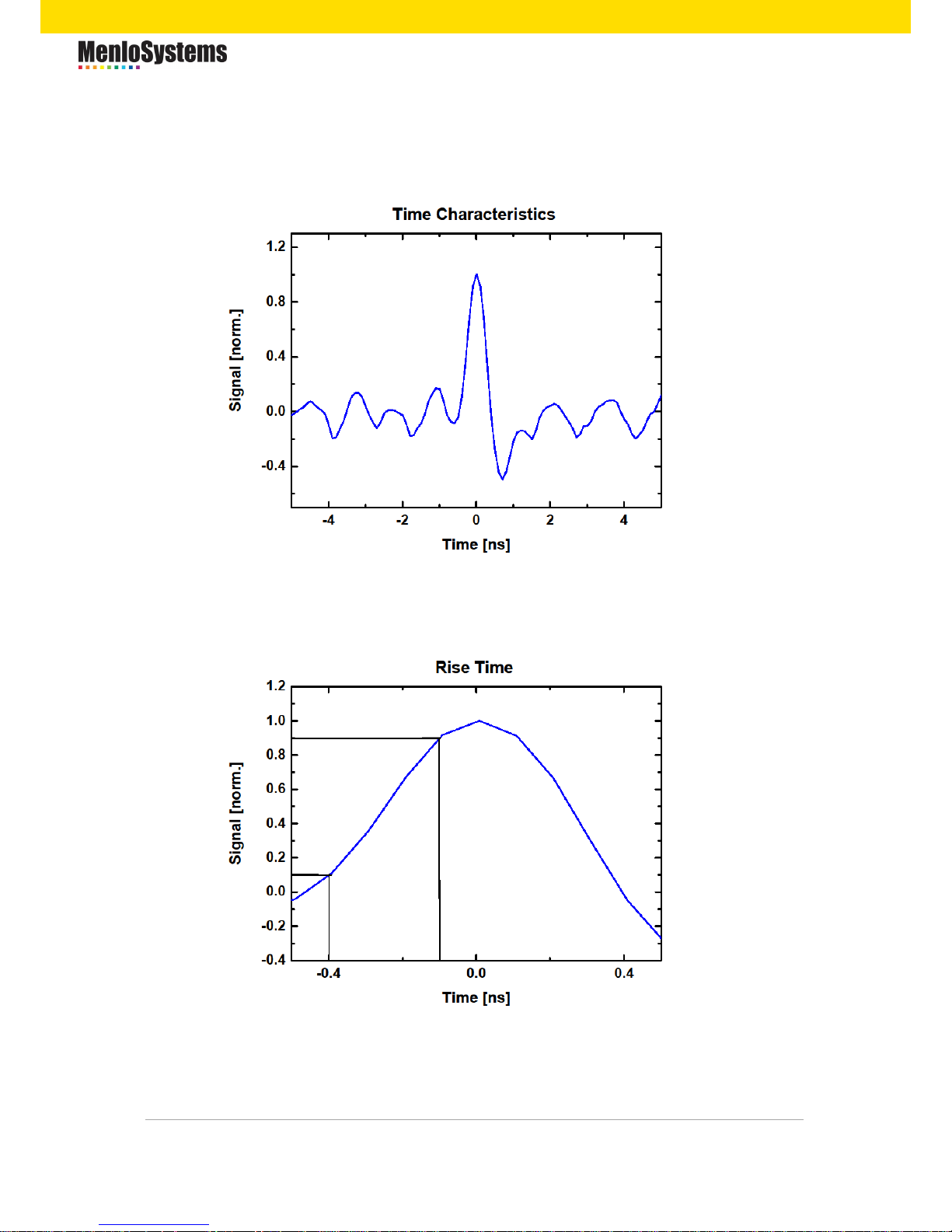
2.3.3 TIME CHARACTERISTICS AND RISE TIME
The time characteristics of the photodetector is shown in the graph below.
The rise time of the photodetector is defined as the time for the signal to rise from 10%
up to 90% of the maximum value.
Page 11
11
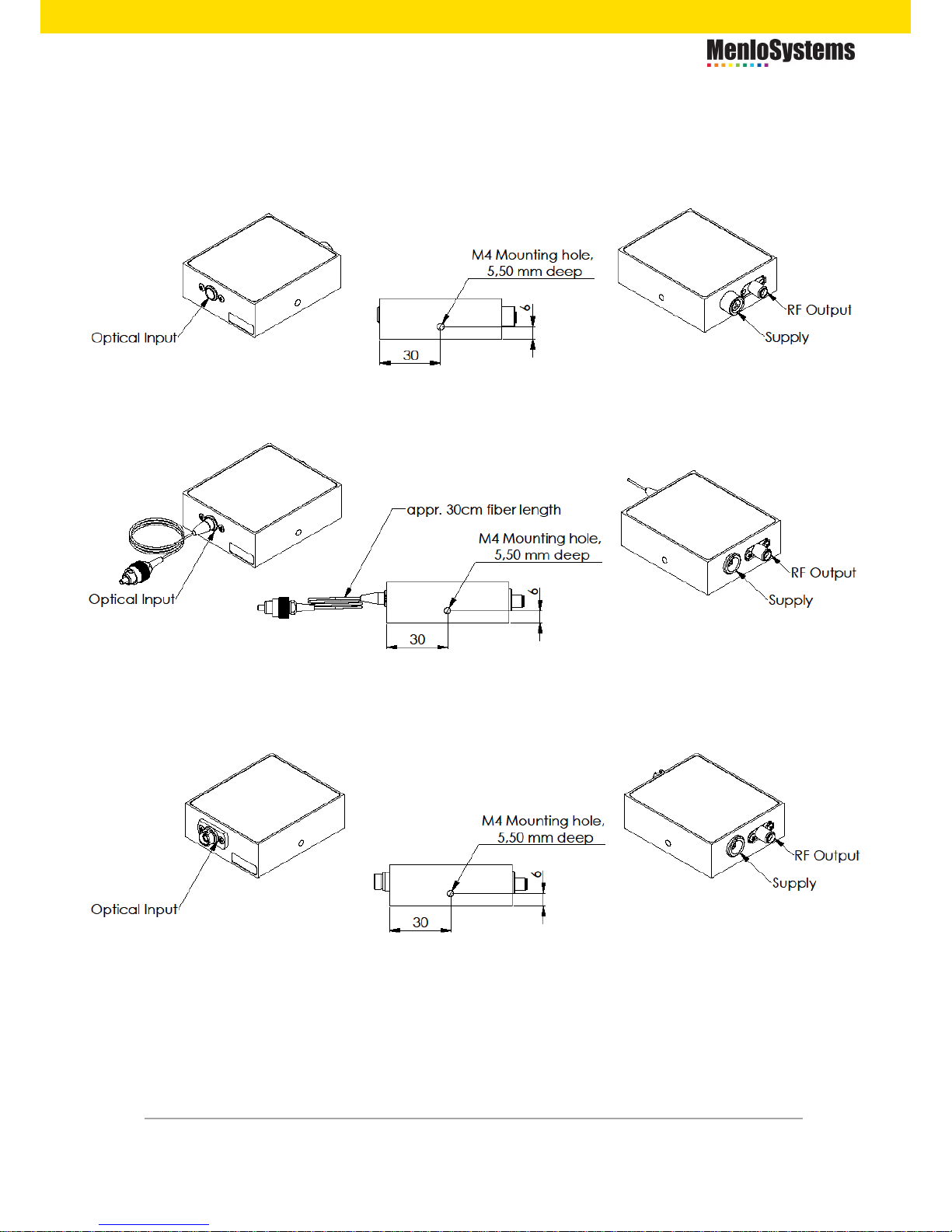
2.4 TECHNICAL DRAWINGS
Free space versions (FPD610-FS-VIS, FPD610-FS-NIR):
Fiber coupled version (FPD610-FC-NIR):
Fiber coupled version (FPD610-FC-VIS):
Dimensional unit is millimeter [mm].
Page 12
12
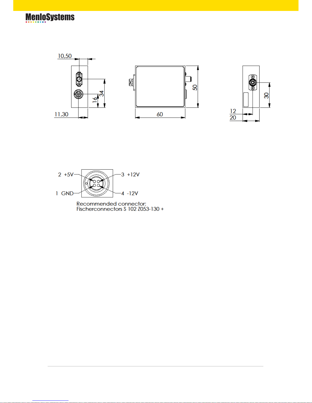
Connection panel of the detector:
Dimensional unit is millimeter [mm].
Four pole male connector on detector.
The dimensions of the power supply are 105x66x36 mm with a 1.5 m long cable in
between the photodetector and the power supply.
Page 13

13
3. INSTALLATION / OPERATION
Note: To prevent humidity condensation when the detector was stored or shipped
at low temperatures, let the system packed for warm-up to room temperature.
The detector should always be mounted and secured for best operation.
Unpack the detector unit. The mounting threat is metric (M4 x 0.7). For
your convenience an imperial adapter is included, if necessary. Mount it
firmly.
Connect the RF Output (SMA jack) to a suitable monitoring device, e.g.
oscilloscope or RF-spectrum-analyzer, with 50Ω impedance. Mount the
device firmly in your setup. Please note that when the device is not
mounted properly, involuntary displacements during operation might occur,
leading to uncontrolled reflections from the device.
Connect the low voltage plug of the provided power supply to the Supply
receptacle at the photo detector.
Plug the power supply into 100 to 240 VAC, 50 to 60 Hz outlet.
Switch on the monitoring device, and apply a light source to the detector.
We recommend centering the incident light on the active area of the
photodetector and not overfilling the detector area. Failing to do so may
result in undesirable capacitance and resistance effects, arising from
inhomogeneities at the edges of the active area of the detector, that distort
the frequency response.
Page 14

14
4. MAINTENANCE
There are no serviceable parts in the photodetector. The housing may be cleaned by
wiping with a soft damp cloth. Do not use any alcohol or organic solvent to clean the
mechanical parts.
If necessary, for freespace version FPD photodetectors, the window of the photo diode
should only be cleaned using isopropyl alcohol and optical grade wipes. For the NIR
fiber coupled detectors, the FC/APC fiber connector may only be cleaned using
appropriate fiber cleaning tools.
If you suspect a problem with your photo detector, please contact Menlo Systems’s
technical support ([email protected]). They will be happy to assist you. For
service requests, please make sure to provide the serial number of your device. For
storage and shipping, please use the case your detector was shipped with.
Page 15

15
5. TROUBLESHOOTING
This section lists error conditions the user might troubleshoot, depending on the error’s
root cause. If the information in this section cannot help, please contact Menlo Systems’
support. The contact information is at the end of this section.
Problem
Suggested Solution
There is no signal
response.
Verify that the power cord is connected and all
connections are secure.
Verify the proper terminating resistor is
installed if using a voltage measurement
device.
Verify that the optical signal wavelength is
within the specified spectral response curve of
the detector (see 2.3.1).
Verify that the optical signal is aligned with the
active area of the detector. Sweep the area in
the vicinity of the center.
Adjust the oscilloscope to see if the signal is
off the visible portion of the oscilloscope.
Output Voltage will
not increase.
The photodetector might be saturated.
Reduce the incident power on the detector
and check again.
Page 16

16
C. CUSTOMER SERVICE
Your system is designed to be maintenance free.
Opening the chassis of the system voids the warranty and exposes the user to
hazardous voltage.
C.1 FACTORY SERVICE & REPAIR
For factory service or repair please call the Menlo Systems’s customer service.
Together with the product specialist they will determine if the equipment requires
service, repair, calibration or replacement.
In case your system has to be returned to Menlo Systems for service or repair, we will
provide an RMA number to you. For more information about the RMA procedure please
read the online information at:
http://www.menlosystems.com/legals/service-plans-returns-rma/
C.2 ADDITIONAL SERVICE PLAN
Menlo Systems offers a Service Plan for all its products. The Service Plan includes onsite service for installation, on-site training and on-site repair service when this is
technically feasible. We also support our customers during measurement campaigns.
For more information please look at:
http://www.menlosystems.com/legals/service-plans-returns-rma/
Worldwide Support Contact except North
America:
Support Contact North America:
Menlo Systems GmbH
Am Klopferspitz 19a
82152 Martinsried
Germany
Phone: +49 89 189166 0
Fax: +49 89 189166 111
Timezone: CET (UTC+1) / CEST (UTC+2)
Menlo Systems, Inc.
56 Sparta Avenue
Newton, NJ 07860
USA
Phone: +1 973 300 4490
Fax: +1 973 300 3600
Timezone: EST (UTC-5) / EDT (UTC-4)
Email: [email protected]
Page 17

17
D. REGULATORY
As required by the WEEE (Waste Electrical and Electronic Equipment) Directive of the
European Community and the corresponding national laws, Menlo Systems offers all
end users in the EC the possibility to return "end of life" units without incurring disposal
charges.
This offer is valid for Menlo Systems electrical and electronic equipment:
Sold after August 13, 2005
Marked correspondingly with the crossed out "wheelie
bin" logo (see right)
Sold to a company or institute within the EC
Currently owned by a company or institute within the EC
Still complete, not disassembled and not contaminated
As the WEEE directive applies to self-contained operational electrical and electronic
products, this end-of-life take-back service does not refer to other Menlo Systems
products, such as:
OEM products, assemblies to be built into a unit by the user
Components
Mechanics and optics
Left over parts of units disassembled by the user (PCB's, housings etc.).
If you wish to return a Menlo Systems unit for waste recovery, please contact Menlo
Systems for further information.
D.1 WASTE TREATMENT IS YOUR OWN RESPONSIBILITY
If you do not return an "end of life" unit to Menlo Systems, you must hand it to a
company specialized in waste recovery. Do not dispose of the unit in a litter bin or at a
public waste disposal site.
D.2 ECOLOGICAL BACKGROUND
It is well known that WEEE pollutes the environment by releasing toxic products during
decomposition. The aim of the European RoHS directive is to reduce the content of
toxic substances in electronic products in the future. The intent of the WEEE directive is
to enforce the recycling of WEEE. A controlled recycling of end of live products will
thereby avoid negative impacts on the environment.
Page 18

18
E. CONTACTS
Headquarters
Menlo Systems GmbH
Am Klopferspitz 19a
82152 Martinsried, Germany
US Office
Menlo Systems, Inc.
56 Sparta Avenue
Newton, NJ 07860, USA
 Loading...