

Mencom Solenoid Valve Connectors General Product Line Information
Solenoid Valve Connectors
EN175301-803, De Facto Industrial Standard
Cordsets | Field Wireables | Accessories
UL File #:
E205538
While most industrial electrical connectors are used in a wide variety of applications, the “solenoid valve connector” is primarily used
on solenoid valves. Over the years as solenoid valves have changed and reduced in size, the solenoid valve connectors have changed
as well.
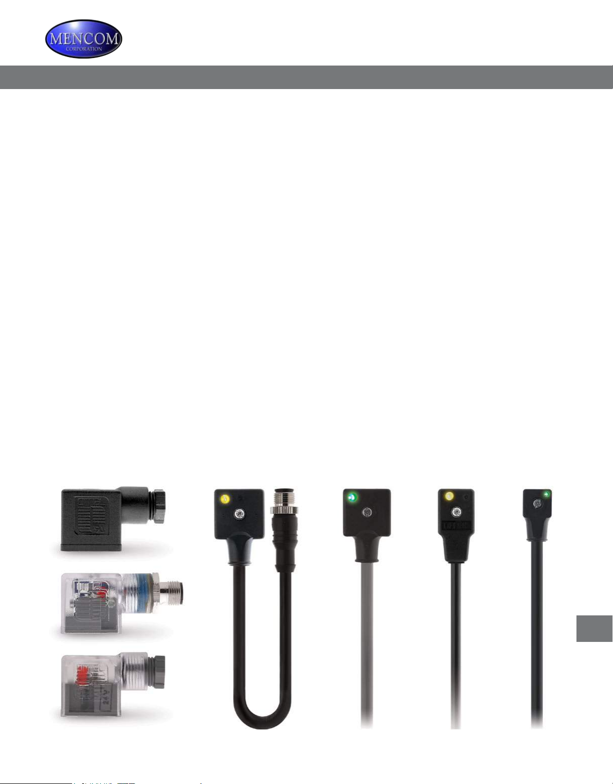
Designed to conform to EN175301-803 (formerly DIN 43650), or to “De Facto” industry standards, Mencom solenoid valve connectors
are available in 5 different interfaces (Form A, Form B, Form C as well as Industry Standard Form B and Industry Standard Form C).
How it works
A solenoid valve is an electromechanically operated valve. The
valve is controlled by an electric current through a solenoid: in
the case of a two-port valve the ow is switched on or off; in
the case of a three-port valve, the outow is switched between
the two outlet ports. Multiple solenoid valves can be placed
together on a manifold.
Where it is used
Solenoid valves are most frequently used to control elements
in uidics. Their tasks are to shut off, release, dose, distribute
or mix uids. They are found in many application areas.
Solenoids offer fast and safe switching, high reliability, long
service life, and compact design.
Features
Our standard valve connector offers a polyamide body with
thermoplastic gasket integrally molded into the face of the
mold connectors. Molded versions utilize a PVC jacket with
18 AWG conductors, while the eld wireables are available in
PG9, PG11, and ½” NPT threaded openings. Valve connectors
with circuitry and suppression aid in diagnostics and
protection of equipment. Several circuitry and suppression
options are available.
Our valve connectors all carry an IP65 Rating.
Valve Connectors
T
T-1
Solenoid Valve Connectors
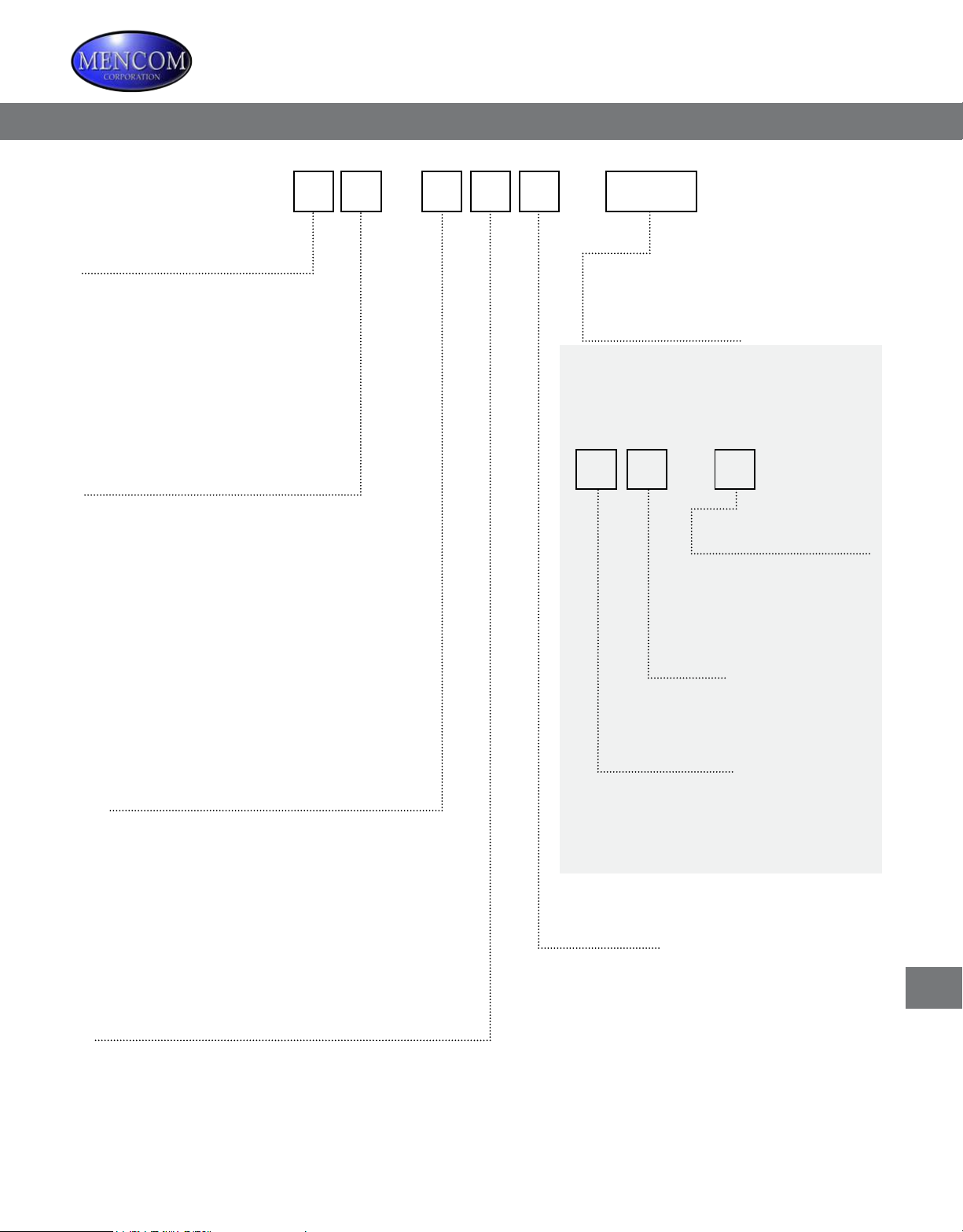
Solenoid Valve Connectors Part Number Matrix
Not all options available with all valve connectors, please consult factory.
V
Style
Black cable unless indicated
A = DIN Form A
B = DIN Form B
C = DIN Form C
D = Ind. Std. Form B {ISB}
E = Ind. Std. Form C {ISC}
F = DIN Form A - Gray
Curcuit Design
A = LED Only; 24V AC/DC
B = LED Only; 120V AC/DC
C = LED w/ Flyback Diode; 10-50V DC
G = LED & MOV
J = LED & MOV
N = No Circuitry
R = LED w/ BRD RECT & MOV; 120V AC/DC
S = Bi-Color LED’s; 10-50V AC/DC
T = Bi-Color LED’s; 120V AC/DC
Z = LED; Zeners; 24V AC/DC
- -
Wiring Design
00 (Double Zero) = STD Cable
50 = Formed Gasket
Or
0
Cong & Wiring
1 = Straight
2 = R/A
3 & Up = Custom
Pins
2,3,4,5, Etc.
Length in Meter
0 (ZERO) = No Cable (Field Wireable)
A = 10M
2 = 2M
5 = 5M
Other lengths are available by request.
Contacts
2 = 2+Ground/Ground Cable Side
3 = 3+Ground/Ground Cable Side
8 = 2+Ground/Ground Opposite Side
9 = 3+Ground/Ground Opposite Side
Connector
1 = MIN
2 = MAC
3 = MDC
4 = NAN
Threads
0 (Zero) = N/A - CBL Version
2 = 1/2 NPT
7 = PG7
9 = PG9
1 = PG11
Valve Connectors
T
T-3
 Loading...