

Page 1
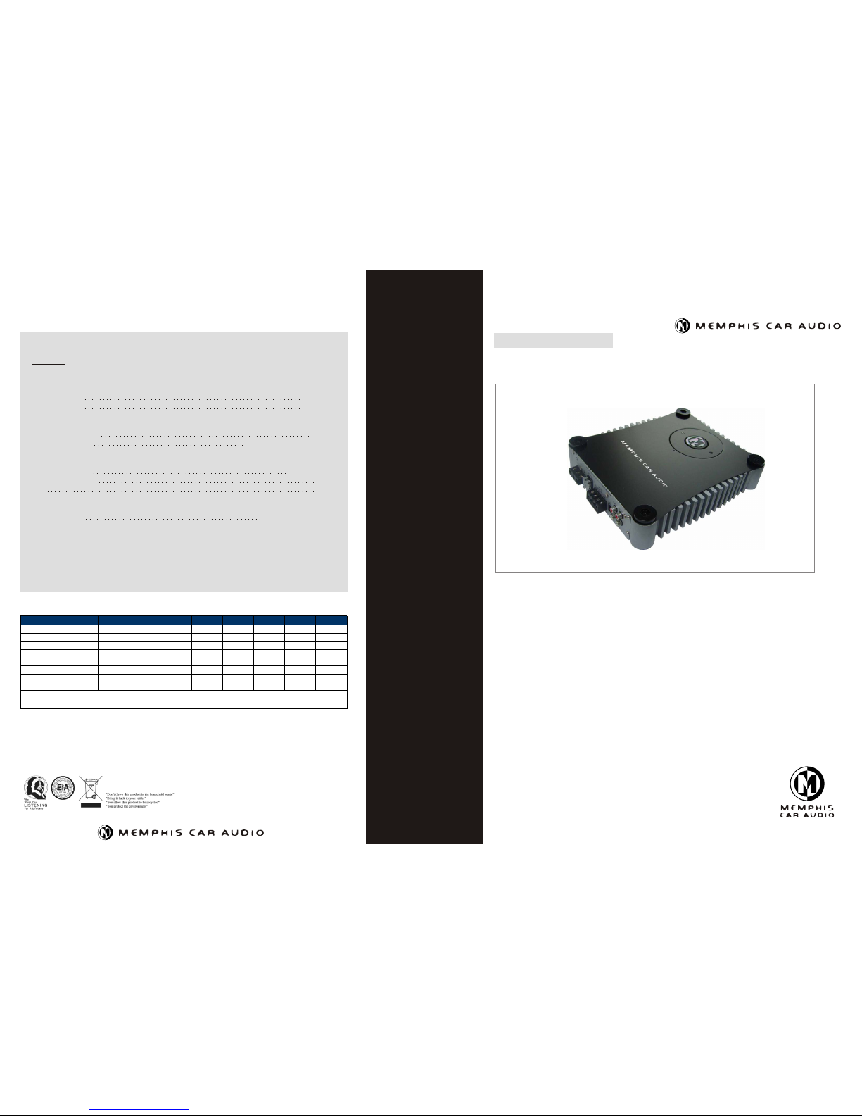
Specifications
DUE TO ON-GOING CONTINUOUS PRODUCT DEVELOPMENT, FEATURES, SPECIFICATIONS AND AVAILABILITY ARE SUBJECT TO CHANGE WITHOUT NOTICE.
dB level example
30 Quiet library, soft whispers
40 Living room, refrigerator, away from traffic
50 Light traffic, normal conversation, quiet office
60 Air conditioner at 20 feet, sewing machine
70 Vacuum cleaner, hair dryer, noisy restaurant
80 Average city traffic, garbage disposals, alarm clock at 2 feet
The following noises can be dangerous under constant exposure
90 Subway, motorcycle, truck traffic, lawn mower
100 Garbage truck, chain saw, pneumatic drill
120 Rock band concert in front of speakers, thunderclap
140 Gunshot blast, jet plane
180 Rocket launching pad
Information courtesy of the Deafness Research Foundation.
2 Channel Power Amplifier
2 Channel Power Amplifier
Product Manual
SC 2.120
CONTINUOUS OUTPUT POWER RATED AT 14.4 VDC AND 1% THD (WATTS):
SC 2.120
SC 2.120
POWER CABLE CALCULATOR
Total Amperage 0-4ft 4-7ft 7-10ft 10-13ft 13-16ft 16-19ft 19-22ft 22-28ft
0-20 14 12 12 10 10 8 8 8
20-35 12 10 8
8
6
4
4
4
2
8
6
4
4
2
2
0
6
4
4
2
2
0
0
6
4
4
2
2
0
0
6
4
4
2
2
0
0
6
4
2
0
0
0
0
35-50 10 8
8
6
6
4
2
50-65 8
65-85 6
85-105 6
105-125 4
125-150 2
The above chart shows cable gauges to be used, if no less than a 0.5 volt drop is acceptable. If aluminum wire or tinned wire i s used, the gauges
sould be of an even larger size to compensate. Cable gauge size calculation takes into account terminal connection resistance. 1 Metre = 3.28 Feet
CON TINUOU S POWER O UTPUT
INTO 4 O HM STER EO 120W X 2CH
INTO 2 O HM STER EO 210W X 2C H
INTO 4 O HM BRID GED 420W X 1 CH
REC OMMEND ED FUSE S IZE 2 X 25A
HEAT SINK DI MENSI ONS 10.5 1"(D) X 1 .91"( H) X 8.66 "(W)
FRE QUENCY R ESPON SE 3dB, 20 Hz - 20KH z
SIG NAL TO NOI SE RATIO >9 0dB
T.H.D 0.0 5 %
SIG NAL INPU T SENSE 30 0 mV - 8.0 V
LP VAR IABLE X- OVER 50H z - 250Hz @ 9dB/O CTAVE
HP VAR IABLE X- OVER 50 Hz - 250Hz @ 6dB/O CTAVE
H ig h er e f f ic i e nc y a t al l v o lu m e le v el s
U ni q u e st a ck i n g ca p ab i li t y
T he b e s t so u nd q u al i t y wi t ho u t t ak i ng u p t oo m u c h ro o m
2 t im e s t o 4 ti m es h i gh e r o ut p ut p o we r t ha n m o st a n al o g am p l if i er
R ed u ce d p o we r c on s um p t io n
A s ma l l a mo u n t of h e at d i ss i p at i on
E as y i ns t a ll a ti o n
C la s s- D D e lt a -S i g ma Te c hn o l og y
2 O hm s t a bl e M OS F ET a m p li f ie r d e si g n
P WM M O SF E T p ow e r su p pl y / M O SF E T ou t pu t s t ag e
A cc u ra t e s ta t ed a m p li f ie r r a ti n gs
R eg u la t e d am p li f i er t e ch n o lo g y
Va r i ab l e hi g h- p a ss c r os s ov e r( 5 0 Hz - 25 0 Hz )
Va r i ab l e lo w -p a s s cr o ss o ve r (5 0 H z- 2 50 H z)
S ub s on i c f il t er ( 2 0H z / O FF )
P ro t e ct i on : T h er m a l / Sh o rt / O v e r- L oa d / D C o ff e st
Th e Bes t Pow er / So und Q ua lit y / Eff ici en cy Fr om Co mpa ct Si ze.
Memphis Car Audio
122 Gayoso Ave.
Memphis, TN 38103
(901) 525-5711
memphiscaraudio.com
Page 2
System Example
2 Channel Power Amplifier
SC 2.120
Operational Details
Set up Stacking
Top Cap
Tapping Screw
(M4 X 20)
Self-Tapping Screw
Second Unit
First Unit
(M4 x 20)
1 Channel Installation
GND
FUSE
25A 25A
FUSE
L
BRIDGE MODE
SPEAKER
R
REMOTE
LPL
OUTPUT
INPUT
R
L
+12V
RMT
Bridge ModeBridge Mode
2 Channel Installation
GND
FUSE
25A 25A
FUSE
L
BRIDGE MODE
SPEAKER
R
REMOTE
LPL
OUTPUT
INPUT
R
L
+12V
RMT
GND
FUSE
25A 25A
FUSE
L
BRIDGE MODE
SPEAKER
R
REMOTE
LPL
OUTPUT
INPUT
R
L
+12V
RMT
12
3
4
5
6
RemoteRemote
ControlControl
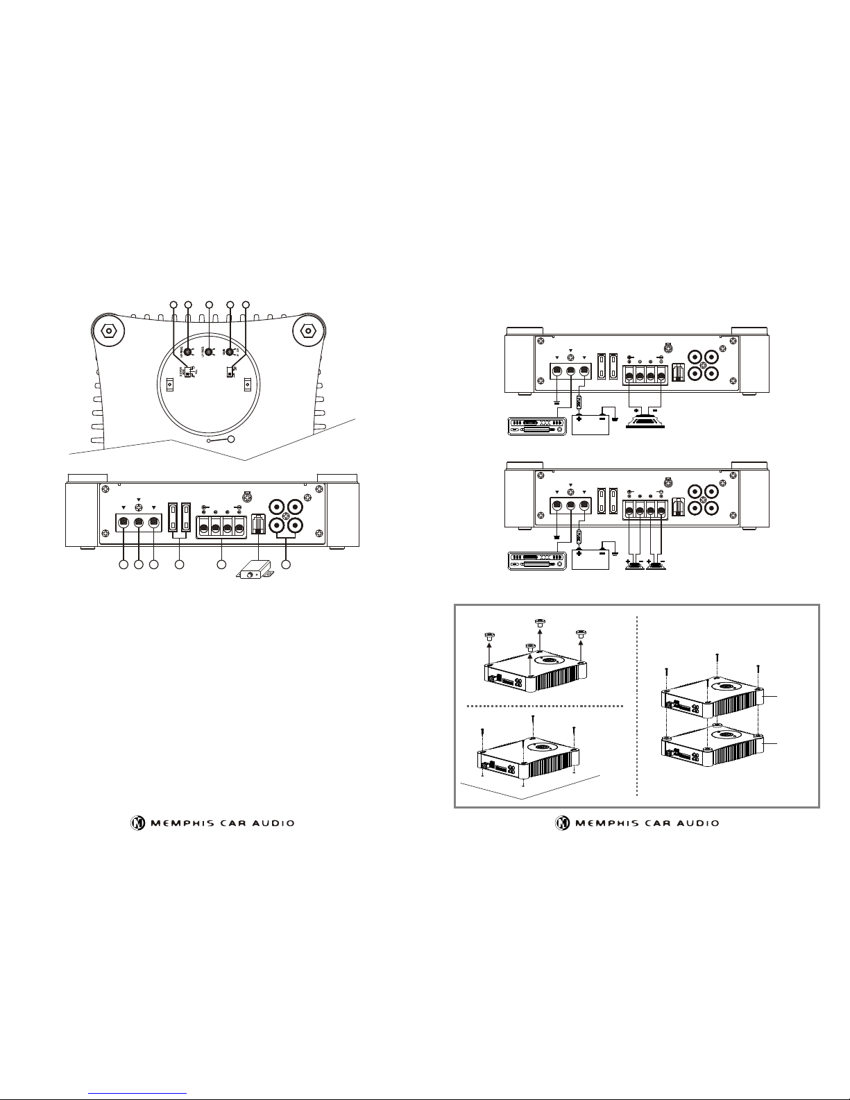
(1)RCA INPUT : Connect these RCA connectors to a head unit with a LOW LEVEL output connection.
RCA OUTPUT: Use these RCA output connectors to connect to a secondary amplifier.
(2)SPEAKER OUTPUT
See installation diagram in this manual for correct speaker connection.
(3)FUSES : Please ensure correct type of fuse is fitted.
(4)+12V INPUT
This must be connected to the vehicle battery positive(+) terminal via correct power cable and with an inline fuse or circuit breaker
at the battery end. NOTE : This is to be the last wire connected during installation, as damage could result.
(5)REMOTE INPUT
This terminal is for turning the amplifier on and off. This requires a switched positive (+)12V to power 'ON' the amplifier, this can be
found on the rear of the head unit in the form of an electric antenna output, or a remote turn-on output. If not available you can wire to the
ACC position on the key.
(6)GROUND INPUT
Connect directly to the vehicle's chassis via correct cable. NOTE : This is to be the first wire connected when wiring up the
amplifier, as damage could result if this is not done.
(7)CROSSOVER SELECTOR
Set the appropriate mode of operation. The 3 positions available are OFF, LP and HP.
(8)SUBSONIC FILTER
This is a selectable switch that filters out 20Hz and below 12dB/octave.
(9)HIGH PASS
Set the crossover switch to HP and turn this control to 65Hz or above when using speaker's smaller than 6 x 9", this feature
is designed to filter out all low bass frequencies that only SUBWOOFERS should produce.
(10)LOW PASS
Set the crossover switch to LP when a subwoofer is connected. Ensure the crossover frequency is set at 100Hz or below.
(11)LEVEL (GAIN)
This allows level adjustment of the input signal. Use this control to correctly match the amplifier. To set this control correctly,
turn the amplifier level to MIN and the head unit to 3/4 volume, with the BASS and TREBLE on zero, then slowly turn up this amplifier
level control towards towards the MAX end of the control. NOTE : If the sound becomes distorted, turn this control down.
(12)POWER, STATUS AND THERMAL LED's
This shows if the amplifier has been correctly powered up and if any faults are present.
SUB
SONIC
20Hz
50Hz
50Hz
250Hz
250Hz
12
9988
1010
1111
77
 Loading...