

Page 1

Copyright
All rights reserved. No part of this publication may be reproduced,
transmitted, transcribed, stored in a retrieval system or translated into any
language or computer language, in any form or by any means, electronic,
mechanical, magnetic, optical, chemical, manual or otherwise, without the
prior written permission of the company. Brands and product names are
trademarks or registered trademarks of their respective companies.
The vendor makes no representations or warranties with respect to the
contents here of and specially disclaims any implied warranties of
merchantability or fitness for any purpose. Further the vendor reserves the
right to revise this publication and to make changes to the contents here of
without obligation to notify any party beforehand. Duplication of this
publication, in part or in whole, is not allowed without first obtaining the
vendor’s approval in writing.
Disclaimer
We makes no warranty of any kind with regard to the content of this user’s
manual and it is subject to be changed without notice and we will not be
responsible for any mistakes found in this user’s manual. All the brand and
product names are trademarks of their respective companies.
FCC Compliance Statement
This equipment has been tested and found to comply with the limits of a
Class B digital device, pursuant to Part 15 of the FCC Rules. These limits are
designed to provide reasonable protection against harmful interference in a
residential installation. This equipment generates, uses and can radiate
radio frequency energy and, if not installed and used in accordance with the
instructions, may cause harmful interference to radio communications.
Operation of this equipment in a residential area is likely to cause harmful
interference in which case the user will be required to correct the
interference at his own expense. However, there is no guarantee that
interference will not occur in a particular installation.
Canadian Department of Communications
Regulatory Statement
This digital apparatus does not exceed Class B limits for radio noise
emissions from digital apparatus set out in the Radio Interference
Regulations of the Canadian Department of Communications.
Page 2

CHAPTER 1. GETTING STARTED............................................................................1
Table of Contents
1.1 Introduction to Your Mainboard....................................................1
1.2 PX845G Series Features:...............................................................1
CHAPTER 2. MAINBOARD SPECIFICATIONS......................................................2
2.1 Hardware........................................................................................2
2.2 BIOS ..............................................................................................6
2.3 Operating System...........................................................................6
2.4 Package Contents...........................................................................6
CHAPTER 3. MAINBOARD CONFIGURATION.....................................................6
3.1 CPU Configuration......................................................................10
CHAPTER 4. INTRODUCTION TO JUMPERS, HEADERS, CONNECTORS
AND SLOTS...................................................................................................................13
4.1 Front Panel Indicators: SW/LED.................................................14
4.2 SPEAKER (Speaker Connector) .................................................15
4.3 IrDA (Infrared Connector)...........................................................15
4.4 ATX 12V Power Connector: ATX_12V......................................16
4.5 ATX 20-pin Power Connector: ATX_PWR.................................16
4.6 Front USB Headers: USB2/ USB3..............................................16
4.7 Wake On LAN Header: WOL .....................................................17
4.8 Voice Genie / BIOS Mirror / AGP Protection function: SW1.....17
4.9 Smart Card Interface Connector: SMART CARD ......................18
4.10 Memory Stick Interface Connector: MEMORY STICK.............18
4.11 Clear CMOS Jumper: JP1............................................................19
4.12 Case Open Warning function: CASE OPEN ...............................19
4.13 Floppy Disk Connector: FDC......................................................20
4.14 Hard Disk Connectors: IDE1/IDE2.............................................20
4.15 Slots .............................................................................................20
CHAPTER 5: AUDIO FUNCTION .............................................................................22
5.1 S/PDIF (Sony/Philips Digital Interface) Connector: SPDIF.......23
5.2 CD-ROM Audio-In Header: CD-IN............................................24
5.3 Front Panel Audio Header: FRONT AUDIO..................................24
i
Page 3

CHAPTER 6: BACK PANEL FEATURES.................................................................25
6.1 PS/2 Mouse / Keyboard Connector: KB/MS...................................25
6.2 USB Connectors: USB ....................................................................25
6.3 Serial and Parallel Interface Ports....................................................26
6.4 Game Port Connector: SOUND.......................................................27
6.5 Audio Port Connectors ....................................................................27
CHAPTER 7: RAM MODULE CONFIGURATION.................... .............................28
7.1 DDR DIMM.....................................................................................28
7.2 DIMM Module Configuration.........................................................28
CHAPTER 8: BIOS SETUP..........................................................................................29
8.1 Main Menu.......................................................................................31
8.2 Advanced Features...........................................................................32
8.3 Peripherals .......................................................................................39
8.4 Power Menu.....................................................................................43
8.5 HW Monitoring ...............................................................................47
8.6 Defaults............................................................................................48
8.7 Exit Menu ........................................................................................49
CHAPTER 9: SOFTWARE SETUP ............................................................................50
9.1 Software List....................................................................................50
9.2 Software Installation........................................................................51
CHAPTER 10: TROUBLESHOOTING......................................................................55
Problem 1:..............................................................................................55
Problem 2:..............................................................................................55
Problem 3:..............................................................................................56
Problem 4:..............................................................................................56
Problem 5:..............................................................................................57
Problem 6:..............................................................................................57
Problem 7:..............................................................................................57
Problem 8:..............................................................................................58
Problem 9:..............................................................................................58
Problem 10:............................................................................................58
Problem 11:............................................................................................59
Problem 12:............................................................................................59
Problem 13:............................................................................................59
Problem 14:............................................................................................60
Problem 15:............................................................................................60
ii
Page 4
Chapter 1. Getting Started
1.1 Introduction to Your Mainboard
Thank you for choosing this mainboard! This mainboard is
designed to take advantage of the latest industry technology to
provide you with the ultimate solution in data processing. In the
tradition of its predecessors, this mainboard continues a
commitment to reliability and performance and strives for full
compliance and compatibility with industry software and
hardware standards.
1.2 PX845G Series Features:
1. Contains on board I/O facilities, which include two serial ports,
a parallel port, a VGA port, a PS/2 mouse port, a PS/2
keyboard port, audio ports, USB ports, a LAN port (optional),
a game port, a Memory Stick™ port, and a Smart Card port.
2. Contains on board IDE faciliti es for IDE devices such as hard
disks and CD-ROM Drives.
3. Supports the Pentium
Complies with PC ATX form factor specifications.
4. Supports popular operating systems such as Windows 9X,
Windows 2000, Windows ME, Windows XP.
®
4 CPU, a leading edge processor.
1
Page 5
Chapter 2. Mainboard Specifications
2.1 Hardware
CPU
Provides Socket 478.
Supports Pentium
generation power for high-end workstations and servers.
Speed
Running at 400/533 MHz Front Side Bus frequency.
The 33MHz 32-bit PCI 2.2 compliant.
®
4 processor providing the new
The AGP 2.0 compliant interface supports 4x data transfer
mode (Supports only 1.5v AGP electrical).
Graphics Controller
256-bit graphics core.
Hardware setup with support for strips and fans.
Integrated 2D/3D graphics accelerator.
Texture mapped 3D with point sampled, Bilinear, Trilinear,
and Anisotropic filtering.
Hardware motion compensation assist for software
MPEG/DVD decode.
Intel Digital Video (DVO) ports add support for digital
displays and TV-out.
Integrated 350MHz RAMDAC.
The PX845G’s analog port utilizes on integrated 350MHz
RAMDAC that can directly drive a standard progressive
scan analog monitor up to resolution of 2048x1536 pixels
with 32-bit color at 60Hz.
The PX845G’s Intel DVO ports are each capable of driving
a 165MHz pixel clock. Each port is capable of driving a
digital display up to 1600x1200 @ 60Hz. When in dualchannel mode, the PX845G can drive a flat panel up to
2048x1536 @ 60Hz or dCRT/HDTV up to 1920x1080 @85Hz.
2
Page 6
Chipset
y
North Bridge – Intel 845G.
South Bridge – Intel 82801DB(ICH4).
RAID – PROMISE PDC20276**.
IO – Winbond Smart IO 83637HF.
LAN Chip – Intel DA82562ET.*
Memory Controller
Up to 2.0 GB 200/266 DDR SDRAM.
Supports 64 MB, 128 MB, 256 MB, 512 MB, and 1 GB DDR
Supports unbuffered non-ECC DIMM only.
Supports only x8 and x16 SDRAM devices wit 4-banks.
Does not support double-sided x16DDR DIMM.
DIMM 1/(2+3) Support up to 2-banks memory size up to 1
GB.
SDRAM technology.
Accelerated Graphics Port interface
Supports a single, 1.5V only, AGP 2.0 compliant device.
AGP interface multiplexed with 2 Intel DVO ports.
Supports ADD cards.
Shadow RAM
Green Functionality
Wakes from power saving sleep mode with any keyboard
Mainboard is equipped with a memory controller
providing shadow RAM and support for ROM BIOS.
Supports PHOENIX-AWARD™ BIOS power management
functionality.
or mouse activity.
BUS Slots
* Onl
Contains 1 AGP slot. (supports ADD cards)
Contains 1 CNR slot (optional).
Contains 6 32-bit PCI bus slots.
for PX845G PRO II ** For PX845G PRO and PX845G
3
Page 7
y
Flash Memory
Supports flash memory functionality.
Supports ESCD functionality.
Ultra ATA 100 Support (IDE1,2)
IDE 1,2 support ultra ATA/100/66/33, BMIDE and PIO
modes.
Independent timing of up to 4 drives, with separate IDE
connections for Primary and Secondary cables.
LAN Integrated*
Supports 10/100 Mbit/s Ethernet.
Supports Wake-On-LAN function.
Supports LAN boot.
Supports PME wake up.
Promise PDC 20276 (RAID IDE 1,2)**
Supports RAID 0 or RAID 1, RAID 0 or RAID 1 non-coexist.
Supports Ultra ATA 133 spec.
Without offering hardware switch to change ATA RAID or
ATA (Microsoft WHQL limitation, Linux Kernel issue).
Default is Ultra ATA133 (emulate Ultra ATA).
Not supporting ATAPI (must remind users to attach ATAPI
device on 2 channels that southbridge support).
§
For more details, please refer to Promise RAID MBFastTrack133
“Lite” user’s manual.
TM
Hardware Monitor Function:
Monitors CPU Fan Speed.
Monitors Chasis Fan Speed.
Monitors System Voltage.
Infrared
Supports IrDA Version 1.0 SIR Protocol with Max. baud
rate up to 115.2K bps.
Supports SHARP ASK-IR Protocol with Max. baud rate up
to 57600 bps.
* Onl
Supports Consumer IR with Wake-Up function.
for PX845G PRO II ** For PX845G PRO and PX845G PRO II
4
Page 8
Memory Stick™ Reader Interface
Smart Card Reader Interface
ISO 7816 protocol compliant.
With 16-byte send / receive FIFOs.
Programmable baud generator
Standard drivers for Windows 98/ME™, Windows 2000™.
AC’97 Sound Codec Onboard
High performance CODEC with high S/N ratio (>90 dB).
Compatible with AC’97 2.2 specification.
6 channels slot selectable DAC output for multi-channel
PC/SC T=0, T=1 compliant
applications.
3D Stereo enhancement.
Digital S/PDIF input/output.
I/O facilities
One multi-mode Parallel Port capable of supporting the
following specifications:
1. Enhanced Parallel Port (EPP).
2. Extended Capabilities Port (ECP).
3. Supports PS/2 compatible bi-directional parallel port.
Supports two serial ports, 16550 UARTs with 16-byte
send/receive FIFOs.
Supports 360KB, 1.2MB, 1.44MB, and 2.88MB floppy disk
Supports Infrared Data Transmission using IrDA.
Supports PS/2 mouse and PS/2 keyboard.
drives.
MIDI compatible.
Game port compatible.
Supports Smart Card and Memory Stick Reader Interface.
5
Page 9
y
Dimensions (ATX form-factor):
305mm x 244mm (WxL)
Universal Serial Bus
Supports two back panel Universal Serial Bus Ports and
four front panel Universal Serial Bus Ports *.
USB 2.0 compliance.
2.2 BIOS
PHOENIX legal BIOS.
Supports APM1.2.
Supports USB legacy.
Supports ACPI Power Management.
2.3 Operating System
Offers the highest performance for Windows 9X,
Windows 2000, Windows ME, Windows XP, etc.
2.4 Package Contents
HDD Cable.
FDD Cable.
USB 2.0 Cable *.
Fully Setup Driver CD.
User’s Manual.
* Onl
for PX845G PRO II
6
Page 10
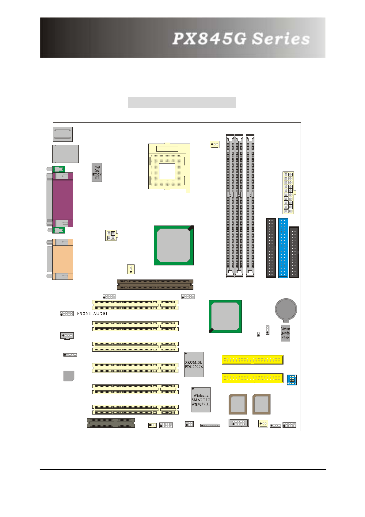
Chapter 3. Mainboard Configuration
Layout of PX845G Pro II
KB/PS2
USB
PRT/COM/VGA
SOUND
ATX_12V
USB2
2
1
AUXFAN
10
9
10
9
1
CPUFAN
ATX_PWR
IDE2 IDE1
DIMM2
DIMM1
DIMM3
FDC
BAT1
Socket 478
Intel
82845G
1
AGP
USB3
2
1
2
1
1
CD-IN
1
SPDIF1
10
9
PCI1
PCI2
PCI3
Intel
82801DB
1
1
CASE OPEN
J1P
RAID IDE2
Codec
PCI4
SW1
RAID IDE1
CNR
PCI5
PCI6
WOL
1
COM2
2
1
U26
BIOS
10
9
1
IrDA
1
MEMORY STICK
2
1
SMART CARD
10
9
U27
BIOS
CHASFAN
1
SPEAKER
1
SW/LED
2
1
10
9
7
Page 11
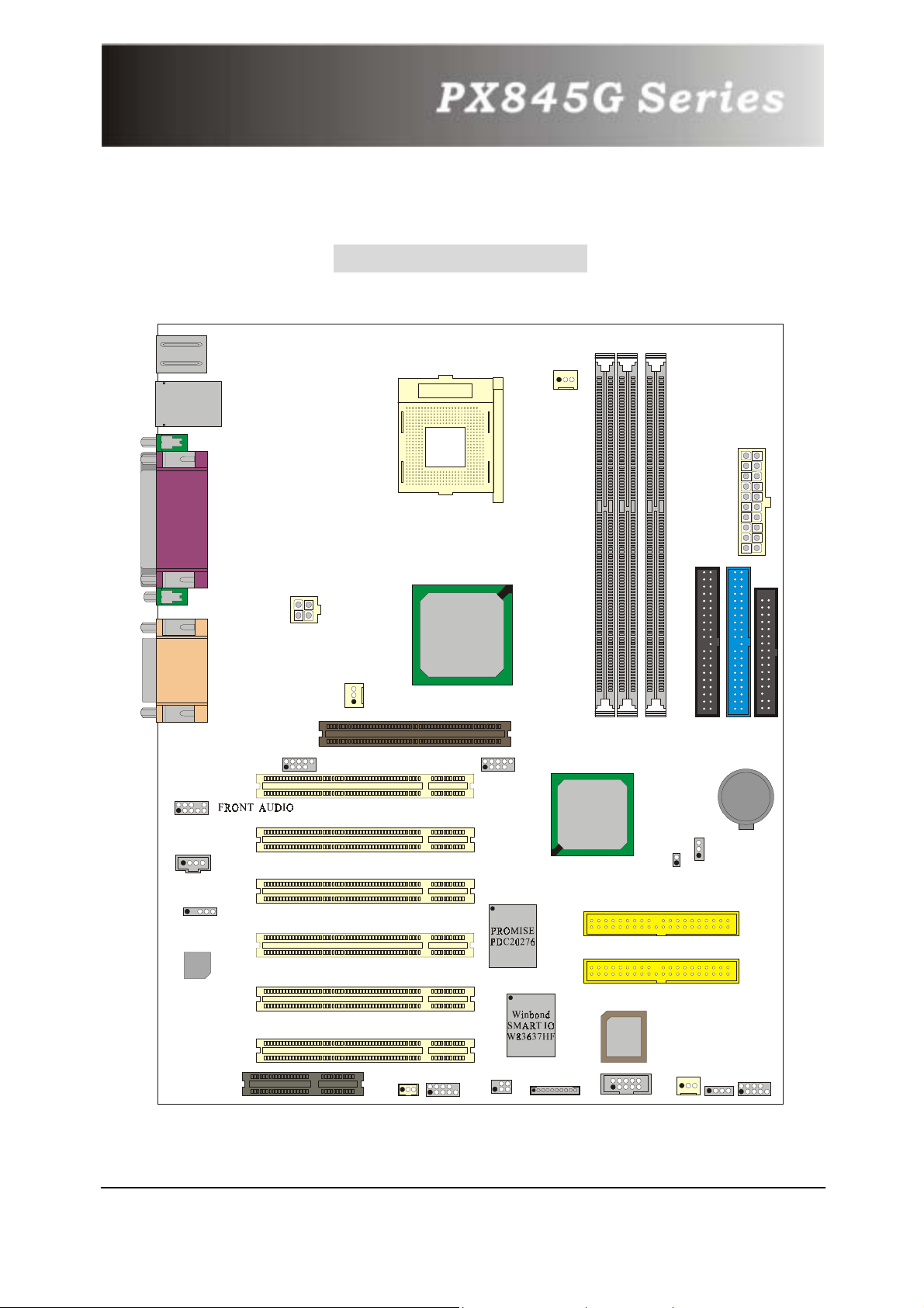
Layout of PX845G Pro
KB/PS2
2
1
USB
PRT/COM/VGA
SOUND
10
9
ATX_12V
USB2
2
1
AUXFAN
10
9
PCI1
Socket 478
1
CPUFAN
ATX_PWR
Intel
82845G
1
AGP
USB3
2
1
IDE2 IDE1
DIMM2
10
9
DIMM1
DIMM3
FDC
BAT1
Intel
82801DB
J1P
1
CD-IN
1
SPDIF1
PCI2
PCI3
1
1
CASE OPEN
RAID IDE2
Codec
PCI4
RAID IDE1
PCI5
U26
BIOS
CNR
PCI6
WOL
1
COM2
2
1
10
9
1
IrDA
1
MEMORY STICK
2
1
SMART CARD
10
9
CHASFAN
1
SPEAKER
1
SW/LED
2
1
10
9
8
Page 12
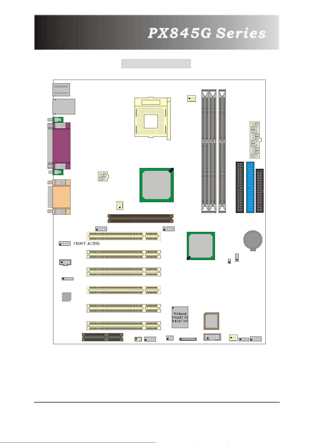
KB/PS2
Layout of PX845G
2
1
USB
PRT/COM/VGA
SOUND
10
9
ATX_12V
USB2
2
1
AUXFAN
10
9
PCI1
Socket 478
1
CPUFAN
ATX_PWR
Intel
82845G
1
AGP
USB3
2
1
IDE2 IDE1
DIMM2
10
9
DIMM1
DIMM3
FDC
BAT1
Intel
82801DB
J1P
1
CD-IN
1
PCI2
PCI3
1
1
CASE OPEN
SPDIF1
Codec
PCI4
U26
PCI5
BIOS
CNR
PCI6
WOL
1
COM2
2
1
10
9
1
IrDA
1
MEMORY STICK
2
1
SMART CARD
10
9
CHASFAN
1
SPEAKER
1
SW/LED
2
1
10
9
9
Page 13
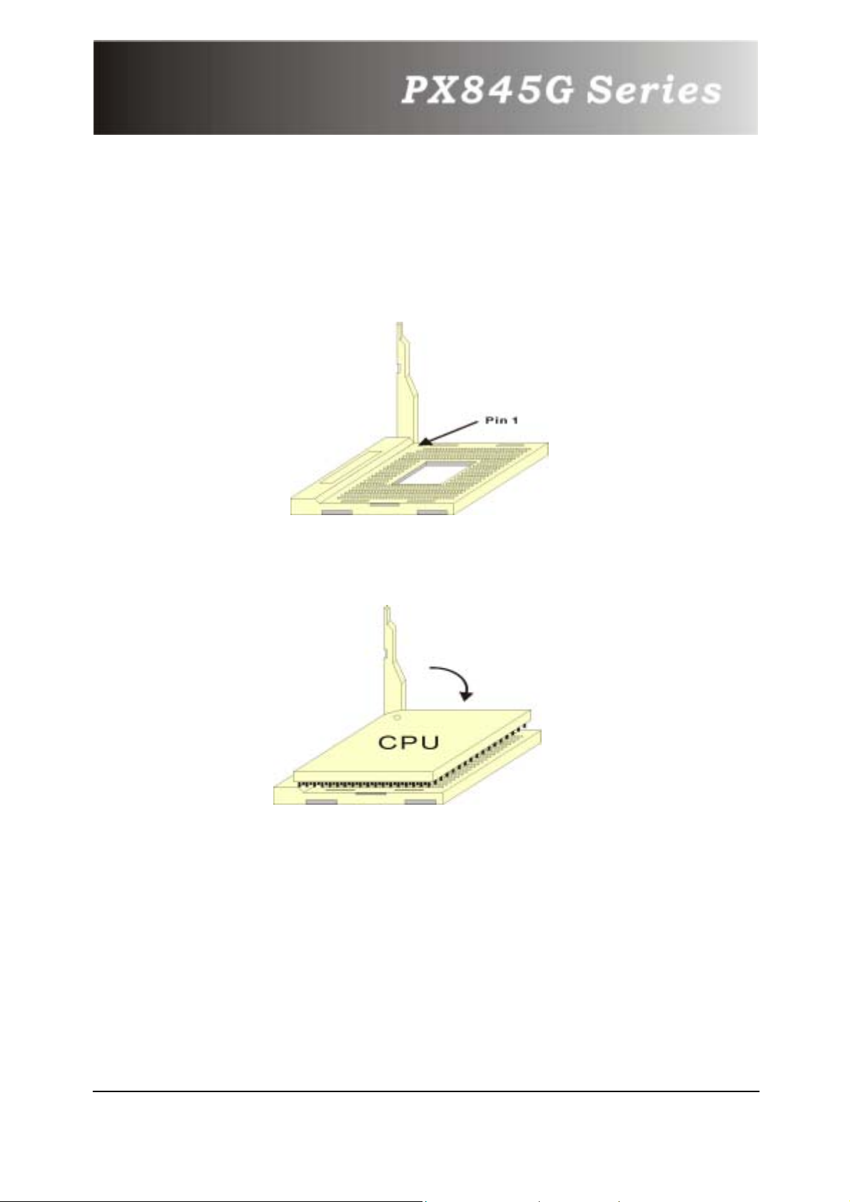
3.1 CPU Configuration
CPU Socket 478 Configuration Steps:
1. Please find the CPU socket on your mainboard and pull the lever sideways
away from the socket, then raise the lever up to a 90-degree angle.
2. Find Pin-1 in the socket and look for the white dot or cut edge in the CPU.
Match Pin-1 with the white dot/cut edge then insert the CPU.
3. Press the lever down. Then Put the CPU fan on the CPU socket and clasp it
with the socket. When the CPU fan is fixed to the CPU socket, put the fan’s
power port into the CPUFAN. After finishing all these steps, the CPU is ready for
use.
10
Page 14

CPU Headers Installation
These three headers introduced here are most related to your CPU installation.
They are the power headers to all the cooling fans on your mainboard. These
fans play an important role on decreasing the temperature of your system.
KB/PS2
CD-IN
SPDIF1
Codec
USB/LAN
PRT/COM/VGA
ATX_12V
SOUND
CNR
USB2
PCI1
PCI2
PCI3
PCI4
PCI5
PCI6
AUXFAN
AGP
WOL
Socket 478
Intel
82845G
COM2
USB3
IrDA
CPUFAN
82801DB
MEMORY STICK
DIMM1
Intel
RAID IDE2
RAID IDE1
BIOS
SMART CARD
DIMM2
DIMM3
CASE OPEN
U17
CHASFAN
U21
BIOS
ATX_PWR
IDE2 IDE1
J1P
SW/LED
SPEAKER
FDC
BAT1
SW1
1
CPUFAN
1
AUXFAN
CHASFAN
1
*The layout is PX845G PRO II
.
11
Page 15
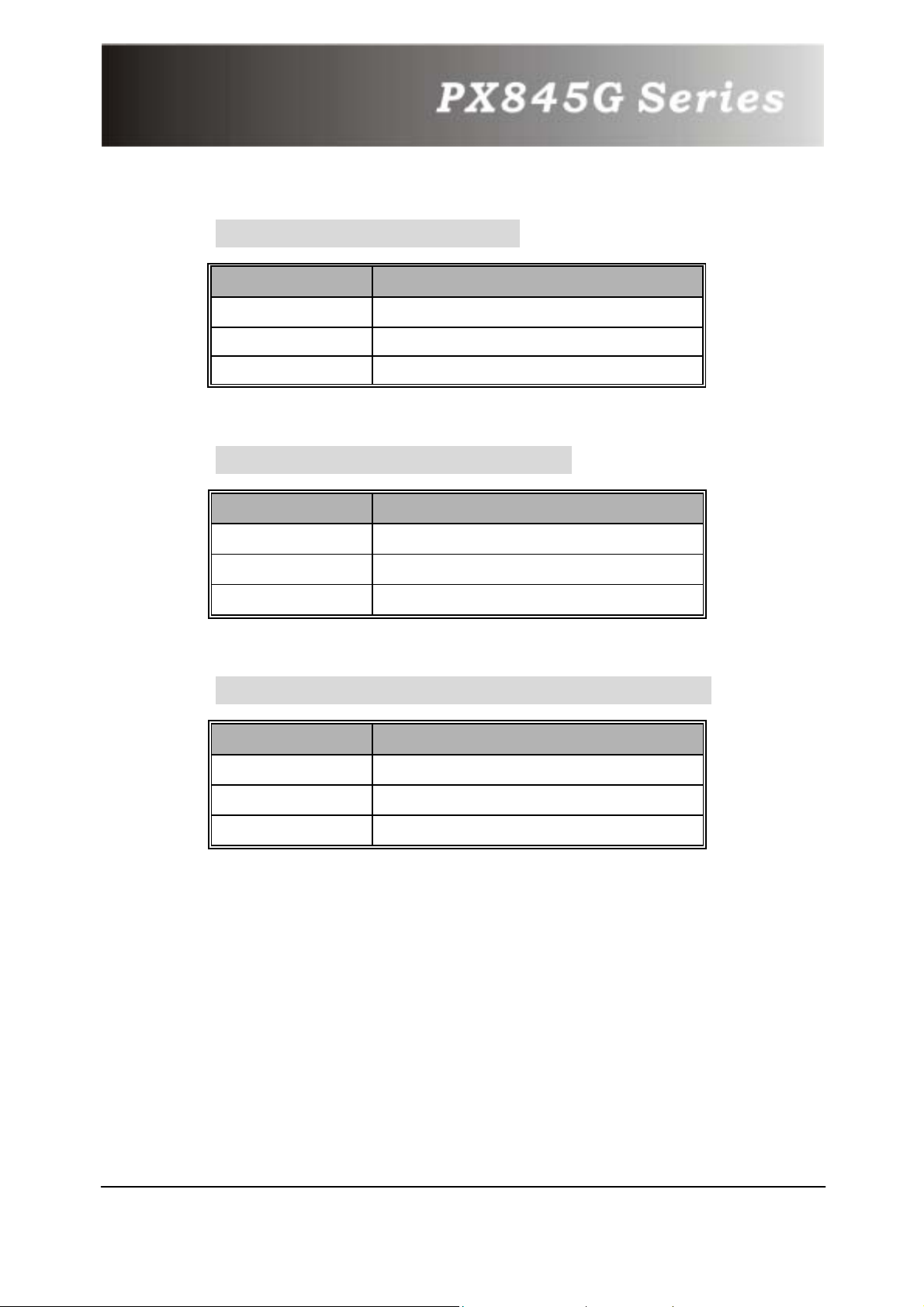
CPU Fan Header: CPUFAN
Pin No. Assignment
1
2
3
GND
+12V
Sense
System Fan Header: CHASFAN
Pin No. Assignment
1
2
3
GND
+12V
Sense
North Bridge Chipset Fan Header: AUXFAN
Pin No. Assignment
1
2
3
GND
+12V
NC
12
Page 16
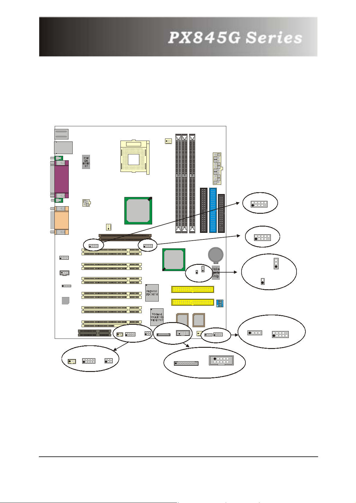
Chapter 4. Introduction to Jumpers,
Headers, Connectors and Slots
KB/PS2
CD-IN
SPDIF1
Codec
USB/LAN
PRT/COM/VGA
ATX _ 1 2 V
SOUND
FRONT AUDIO
CNR
USB2
AUXFAN
PCI1
PCI2
PCI3
PCI4
PCI5
PCI6
WOL
WOL
AGP
Socket 478
Intel
82845G
COM2
COM2
IrDA
IrDA
USB3
CPUFAN
82801DB
MEMORY STICK
Intel
RAID IDE2
RAID IDE1
SMART CARD
DIMM1
BIOS
DIMM2
DIMM3
CASE OPEN
BIOS
CHASFAN
ATX _ P WR
IDE2 IDE1
J1P
SPEAKER
FDC
BAT1
SW/LED
USB2
2
1
2
1
USB3
10
9
1
CASE OPEN
1
1
SPEAKER
2
1
10
9
J1P
SW/LED
10
9
IrDA
COM2
COM2
WOL
WOL
2
1
1
*The layout is PX845G PRO II.
IrDA
6
2
10
9
5
1
MEMORY STICK
1
2
1
SMART CARD
10
9
13
Page 17
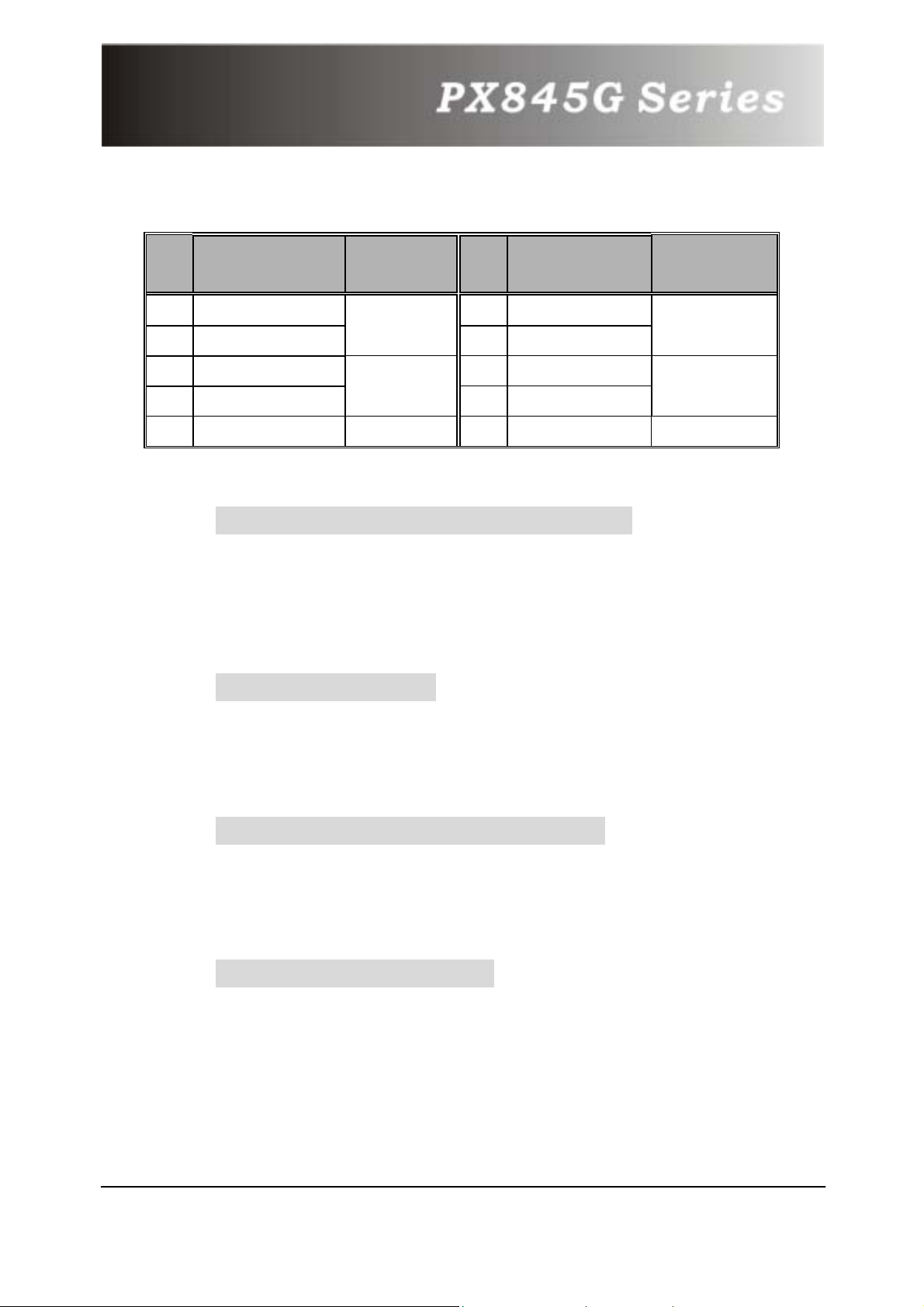
4.1 Front Panel Indicators: SW/LED
Pin Assignment Function Pin Assignment Function
No.
No.
1
3
5
7
9
HD LED (+)
HD LED (-)
Reset Control (-)
Reset Control(+)
HD LED (Hard Drive LED Connector)
This connector can be attached to an LED on the front panel of
a computer case. The LED will flicker during disk activity. This
disk activity only applies to those IDE drives directly attached to
the system board.
RST (Reset Button)
This connector can be attached to a momentary SPST switch.
This switch is usually open and when closed will cause the
mainboard to reset and run the POST (Power On Self Test).
Hard Drive
LED
Reset Button
NA NA
2
4
6
8
10
Powe r LED (+)
Power LED (-)
Power Button(+)
Power Button(-)
NC NC
POWER LED
Power-on
Button
PWR-LED (Power LED Connector)
This connector can be attached to an LED on the front panel of
a computer case. The LED will illuminate while the computer is
powered on.
PWR ON (Power Button)
This connector can be attached to a front panel power switch.
The switch must pull the Power Button pin to ground for at least
50 ms to signal the power supply to switch on or off. (The time
required is due to internal debounce circuitry on the system
board). At least two seconds must pass before the power supply
will recognize another on/off signal.
14
Page 18
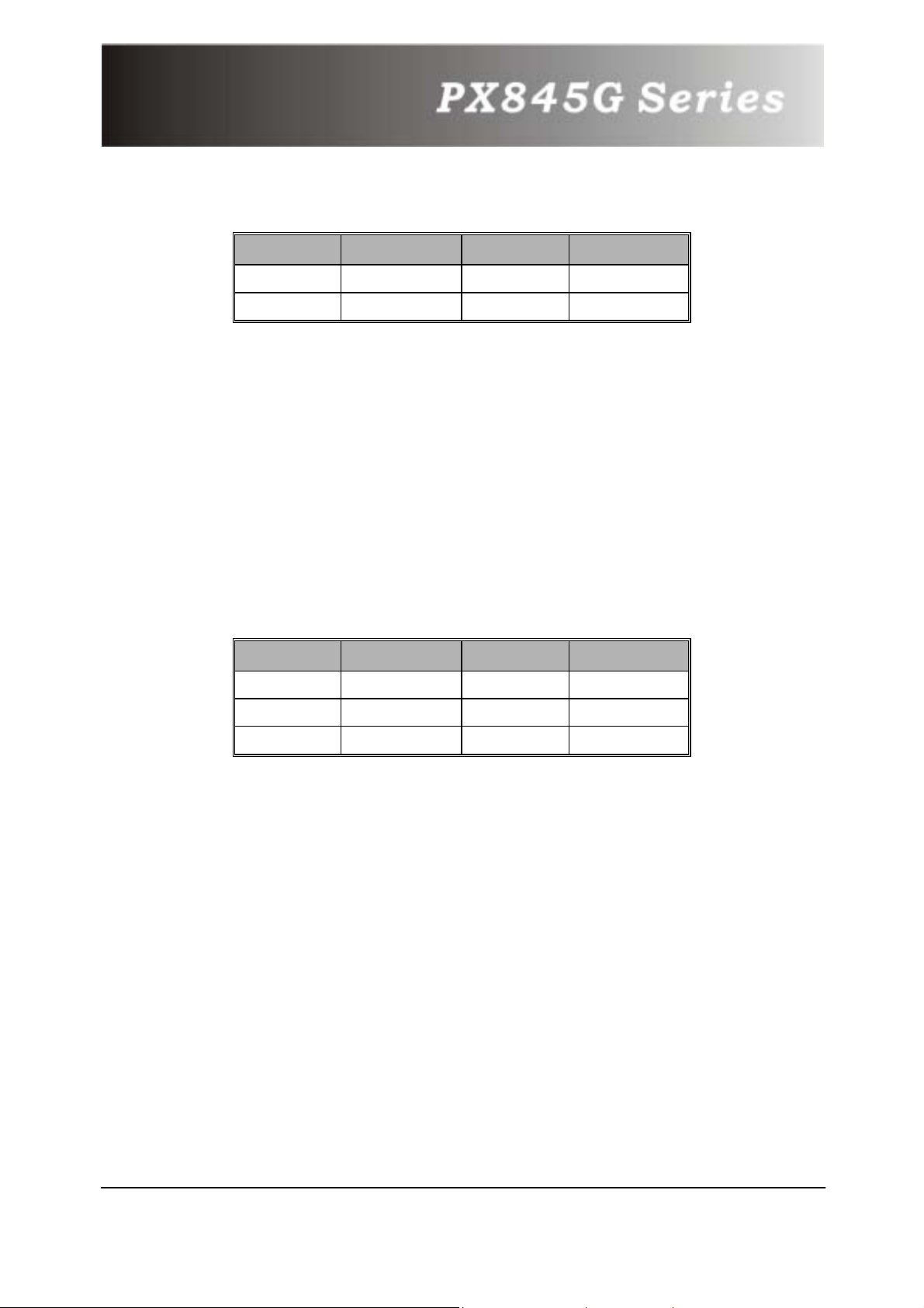
4.2 SPEAKER (Speaker Connector)
PIN Assignment PIN Assignment
1
2
PC_BEEP
NC
3
4
GND
+5V
An off-board speaker can be installed on the mainboard as a
manufacturing option. An off-board speaker can be connected to
the mainboard at the front panel connector. The speaker
(onboard or off-board) provides error beep code information
during the Power On Self-Test when the computer cannot use
the video interface. The speaker is not connected to the audio
subsystem and does not receive output from the audio
subsystem.
4.3 IrDA (Infrared Connector)
PIN Assignment PIN Assignment
1
2
NC
NC
4
5
GND
IR_TX
3
PWR
6
IR_RX
This IrDA connector can be configured to support wireless
infrared module, it is used to attach to an infrared sensing
device. After the IrDA interface is configured, connectionless
data transfer to and from portable devices such as laptops,
PDAs is possible.
15
Page 19
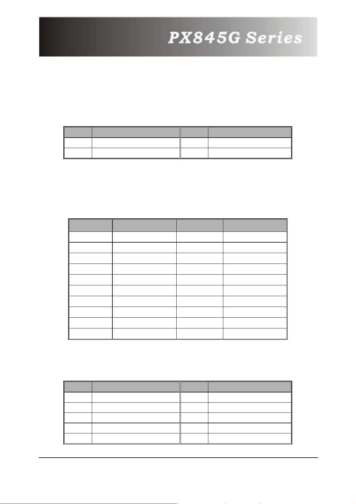
4.4 ATX 12V Power Connector: ATX_12V
This ATX power supply uses 4-pin connector. Please plug it
before plugging the ATX 20-pin power connector.
Pin Assignment Pin Assignment
1
GND
3
+12V
2
GND
4
+12V
4.5 ATX 20-pin Power Connector: ATX_PWR
This ATX power supply uses 20-pin connector. During your
configuration, please plug it into the right direction.
PIN Assignment PIN Assignment
1
2
3
4 +5V 14 PS_ON
5
6
7 GND 17 GND
8 NC 18 -5V
9
+3.3V 11 +3.3V
+3.3V 12 -12V
GND 13 GND
GND 15 GND
+5V 16 GND
5V_SB 19 +5V
10
+12V 20 +5V
4.6 Front USB Headers: USB2/ USB3
Pin Assignment Pin Assignment
1
3 DATA_A- 4 DATA_B-
5
7
9
+5V(fused)
DATA_A+
GND
NC
2
6
8
10
16
+5V(fused)
DATA_B+
GND
OVC
Page 20
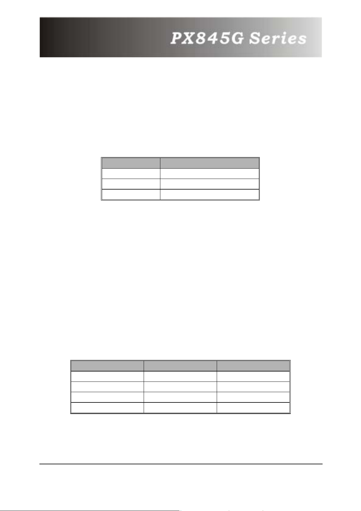
4.7 Wake On LAN Header: WOL
This motherboard supports Wake On LAN function. To use this
function, a network card with chipset that supports this feature
is needed. Meanwhile, you have to connect a cable from LAN
card to your motherboard WOL connector.
Pin Assignment
1
5V SB
2
3
GND
Wake up
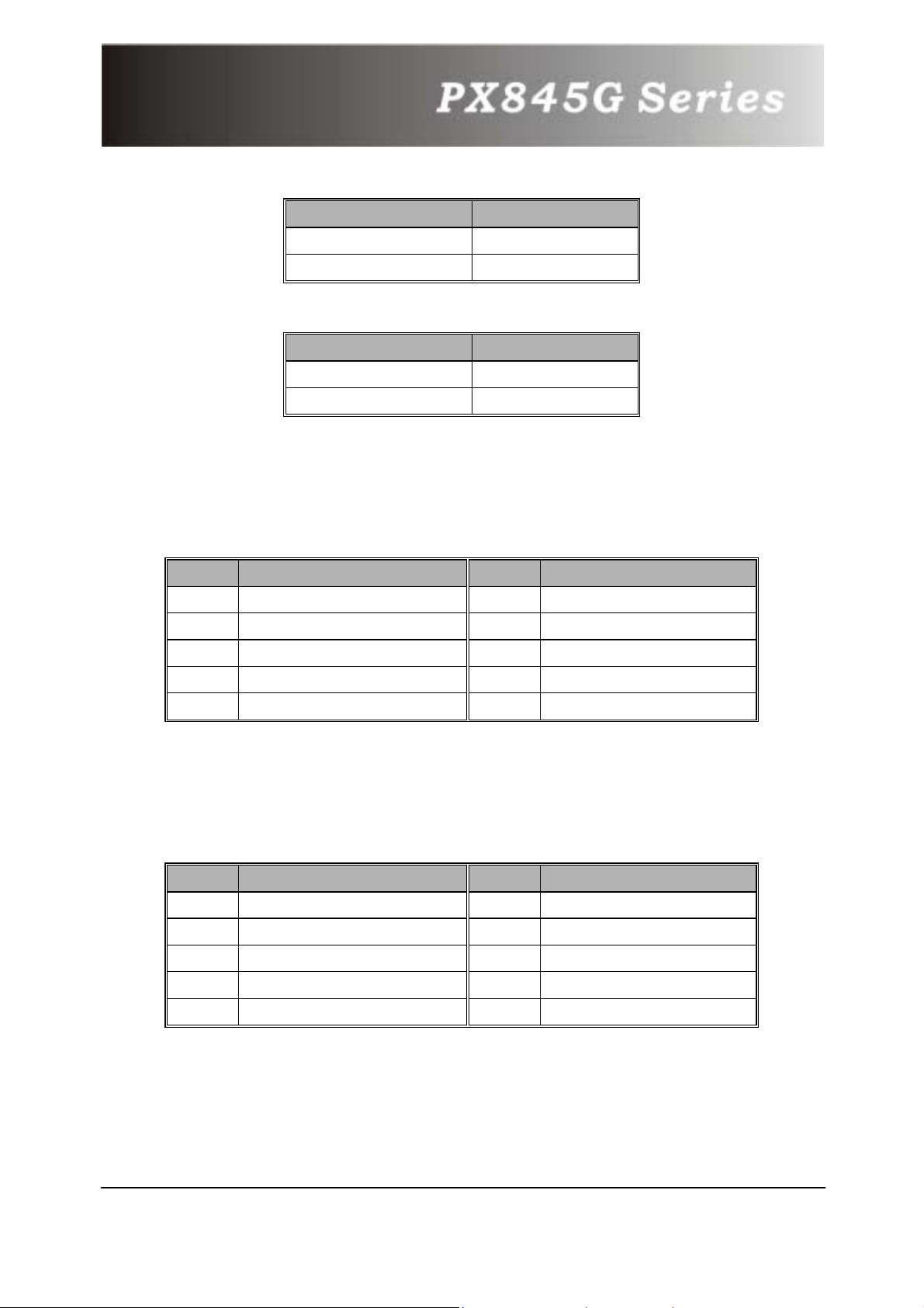
4.8 Voice Genie / BIOS Mirror / AGP
Protection function: SW1
This switch supports three different functions which you can
control all of them by adjusting this switch. With the SW1-1 and
SW1-2, you can change the voice reminding function settings in
your motherboard. With the SW1-3, you can enable or disabled
the AGP Protection, because the AGP slot only supports 1.5V
cards, . On the other hand, with the SW1-4, you can activate the
BIOS Mirror function that can choose which BIOS ROM you want
to use.
Voice Genie
Voice Genie
English (default)
SW1-1
ON ON
SW1-2
Chinese
Japanese OFF ON
German
ON OFF
OFF OFF
17
Page 21
AGP Protection
AGP Protection SW1-3
Enable (default) ON
Disable
OFF
BIOS Mirror (only for PX845G Pro II)
BIOS Mirror SW1-4
Normal (default)
Rescue
ON (U26)
OFF (U27)
4.9 Smart Card Interface Connector:
SMART CARD
Pin Assignment Pin Assignment
1
2 GND 7 IO-
3
4
5 NC 10 PSNT
PWR
PWCTL
RST-
6
8
9
RWLED
NC
CLK
4.10 Memory Stick Interface Connector:
MEMORY STICK
Pin Assignment Pin Assignment
1
2
3
4
5
GND
MS1
PWR
MS2
MS3
6
7
8
9
10
MS4
MS5
CLK
CTL-
RWLED
18
Page 22
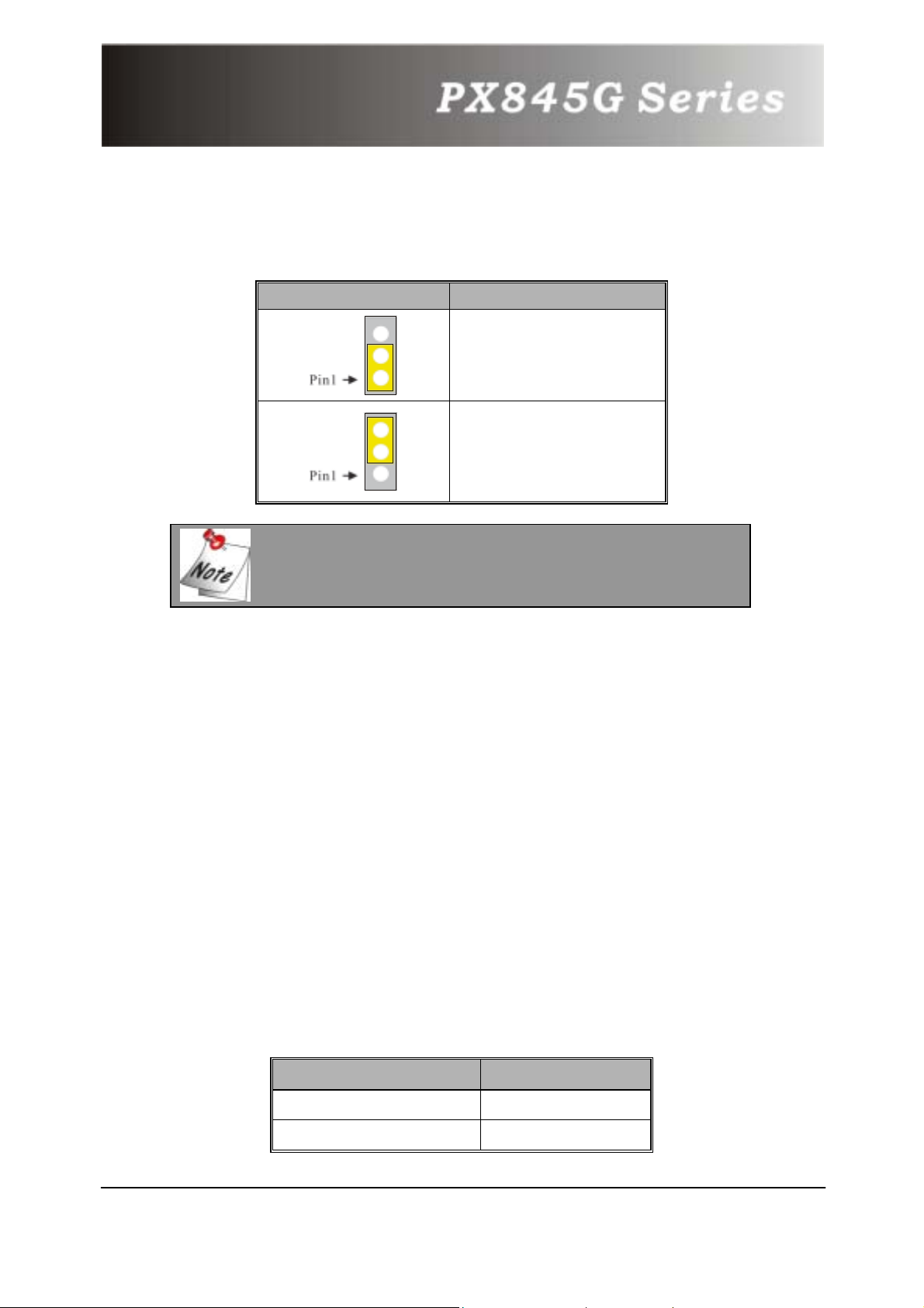
4.11 Clear CMOS Jumper: JP1
JP1 Assignment
Pin 1-2 Close
Normal (default)
Pin 2-3 Close
Clear CMOS
The following procedures are for resetting
the BIOS password. It is important to
follow these instructions closely.
1. Turn off your system and remove AC power line.
2. Set JP1 to OFF (2-3 Closed).
3. Wait several seconds.
4. Set JP1 to ON (1-2 closed).
5. Connect the AC power line and turn on your system.
6. Reset your desired password or clear CMOS data.
4.12 Case Open Warning function: CASE
OPEN
If this function is set to “Enabled” in BIOS and the case is
opened by others, the system will automatically show alert
messages on the screen display when you power on your
computer. On the contrary, if this function is set to “Disabled” in
BIOS, the system will not show alert messages when you power
on your computer even if someone opened the case.
Case Open Assignment
1 INTRUDR-
2 GND
19
Page 23
4.13 Floppy Disk Connector: FDC
The mainboard provides a standard floppy disk connector (FDC)
that supports 360K, 720K, 1.2M, 1.44M and 2.88M floppy disk
types. This connector supports the provided floppy drive ribbon
cables.
4.14 Hard Disk Connectors: IDE1/IDE2
This mainboard has a 32-bit Enhanced PCI IDE Controller that
provides PIO Mode 0~4, Bus Master, and Ultra DMA/33, Ultra
DMA/66, Ultra DMA/100 functionality. It has two HDD
connectors IDE1 (primary) and IDE2 (secondary).
IDE1 (Primary IDE Connector)
The first hard drive should always be connected to IDE1. IDE1
can connect a Master and a Slave drive. You must configure the
second hard drive on IDE1 to Slave mode by setting the jumper
accordingly.
IDE2 (Secondary IDE Connector)
The IDE2 controller can also support a Master and a Slave drive.
The configuration is similar to IDE1. The second drive on this
controller must be set to slave mode.
RAID IDE1 and RAID IDE2 **
The RAID IDE1 and RAID IDE2 support Ultra ATA133. RAID
IDE1 and RAID IDE2 can also connect a Master and a Slave
drive. RAID IDE1 and RAID IDE2 support RAID0 or RAID1,
RAID0 and RAID1 non-coexist.
§
Please read the Promise Raid Function User’s manual, to
understand the details of Chipset 20276.
** For PX845GPRO and PX845G PRO II
20
Page 24
4.15 Slots
The slots in this mainboard are designed to hold expansion
cards and connect them to the system bus. Expansion slots are
a means of adding or enhancing the mainboard's features and
capabilities. With these efficient facilities, you can increase the
mainboard's capabilities by adding hardware that performs tasks
that are not part of the basic system.
AGP (Accelerated Graphics Port) Slot
This mainboard supports video cards for PCI slots but is also
equipped with an Accelerated Graphics Port (AGP). An AGP card
will take advantage of AGP technology for improved video
efficiency and performance, especially with 3D graphics. There
is AGP protection circuit on this mainboard. When you use 1x or
2X AGP Card (3.3V Core) to install on this mainboard, you will
not be able to power on this mainboard. Please replace 4x AGP
card or use on board VGA to restart.
The PX845G provides interfaces to a progressive scan analog
monitor and two DVOs (muxed with AGP) capable of driving an
ADD card. The digital display channels are capable of driving a
variety of DVO devices (e.g. TMDS, LVDS and TV-OUT).
CNR (Communication Network Riser) Slot (optional)
The CNR specification is compliant Intel CNR specification that
defines a hardware scalable riser card interface, which supports
audio, modem, USB and LAN.
PCI (Peripheral Component Interconnect) Slots
This mainboard is equipped with 6 standard PCI slots. PCI 6 is
master for PX845G only. PCI stands for Peripheral Component
Interconnect and is a bus standard for expansion cards, which
has, for the most part, supplanted the older ISA bus standard.
This PCI slot is designated as 32-bit.
21
Page 25
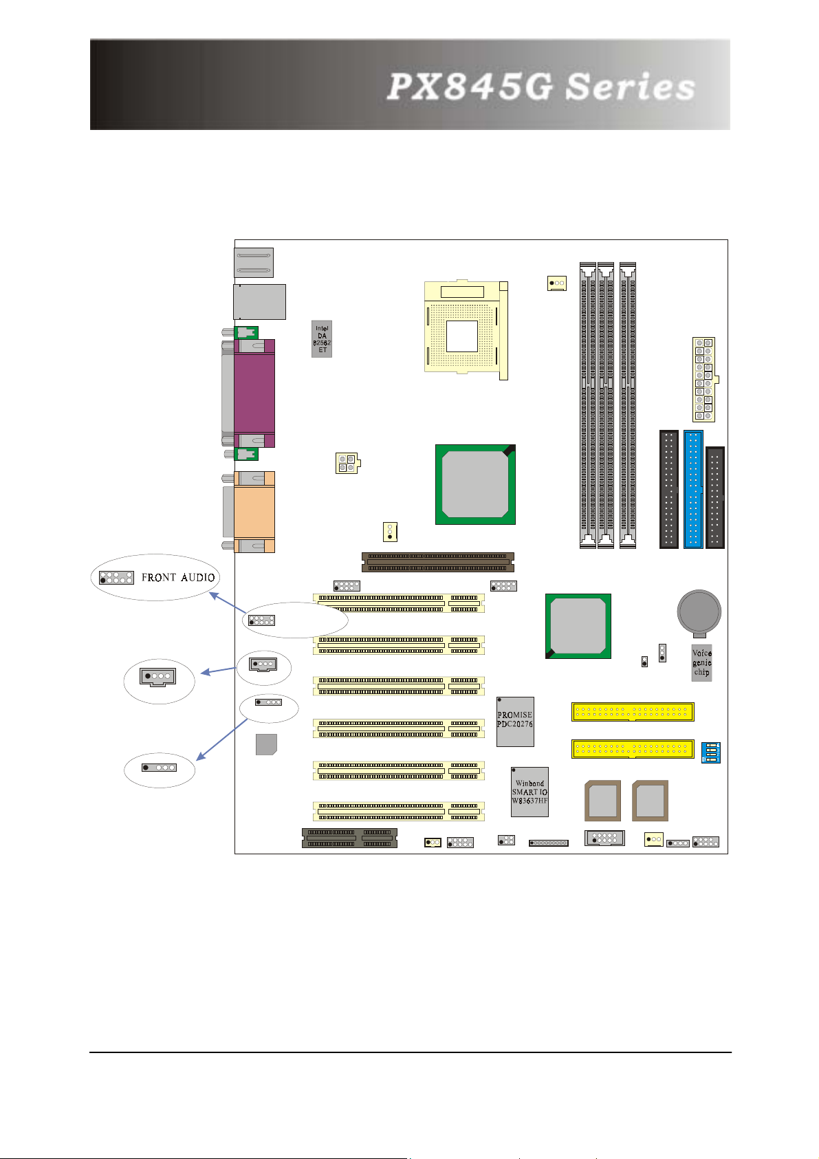
Chapter 5: Audio Function
KB/PS2
USB/LAN
PRT/COM/VGA
ATX_12V
Socket 478
Intel
CPUFAN
ATX_PWR
82845G
SOUND
10
2
9
1
FRONT AUDIO
1
CD-IN
CD-IN
SPDIF1
Codec
1
SPDIF1
AUXFAN
USB2
PCI1
PCI2
PCI3
PCI4
PCI5
AGP
2
1
USB3
10
9
DIMM1
Intel
82801DB
RAID IDE2
RAID IDE1
BIOS
DIMM2
DIMM3
CASE OPEN
U21U17
BIOS
IDE2 IDE1
J1P
FDC
BAT1
SW1
CNR
PCI6
WOL
COM2
IrDA
MEMORY STICK
SMART CARD
CHASFAN
SPEAKER
SW/LED
*The layout is PX845G PRO II
.
22
Page 26
5.1 S/PDIF (Sony/Philips Digital Interface)
Connector: SPDIF
S/PDIF (Sony/Philips Digital Interface) is a newest audio transfer file
format, which provides impressive quality through optical fiber and
allows you to enjoy digital audio instead of analog audio. Normally
there are one S/PDIF outputs as shown, one for RCA connector, the
most common one used for consumer audio products, and the other
for optical connector with better audio quality. Through a specific
audio cable, you can connect the S/PDIF connector to other end of
the S/PDIF audio module, which bears S/PDIF digital output.
SPDIF Assignment
1
2 NC
3
4
5
PWR
SPD_OUT
GND
SPD_IN
Super 5.1 Channel Audio Effect
This motherboard comes with an ALC650 Codec, which supports high
quality of 5.1 Channel audio effect, bringing you a brand new audio
experience. On the strength of the innovative design of ALC650,
you’re able to use standard line-jacks for surround audio output
without connection any external module. To apply this function, you
have to install the audio driver in the bonus Pack CD as well as an
audio application supporting 5.1 Channel. Picture bellow represents
the standard location of all speakers in 5.1 Channel sound track.
Please connect the plug of your front speakers to the green “Speaker
out” port, rear speakers’ plug to the blue “Line in” port and both of
the center and subwoofer speakers to the red “MIC in” port.
23
Page 27
5.2 CD-ROM Audio-In Header: CD-IN
This header is used to connect CD Audio Cable from CD-ROM / DVD
drive to onboard sound.
Pin No. Assignment
1
2
3
4
Left Channel Input
GND
GND
Right Channel Input
5.3 Front Panel Audio Header: FRONT AUDIO
If your housing has been designed with an Audio port on the front
panel. You have to remove the jumper caps before connecting the
front panel Audio port; then you can use either panel. On the other
hand, if your housing does not have Audio port on the front panel,
please do not remove the jumper caps.
Pin No. Assignment Pin No. Assignment
1
3 FP_VREF 4 +5V
5
FP_MIC
SPOUT_R
(From IC)
2
6
GND
SPOUT_R
(To Connector)
7
9
NC
SPOUT_L
(From IC)
8
10
(To Connector)
NC
SPOUT_L
Note: if you maintain the caps place, jumper cap 1 is on pin5, pin6
and jumper cap 2: pin9, pin10
24
Page 28
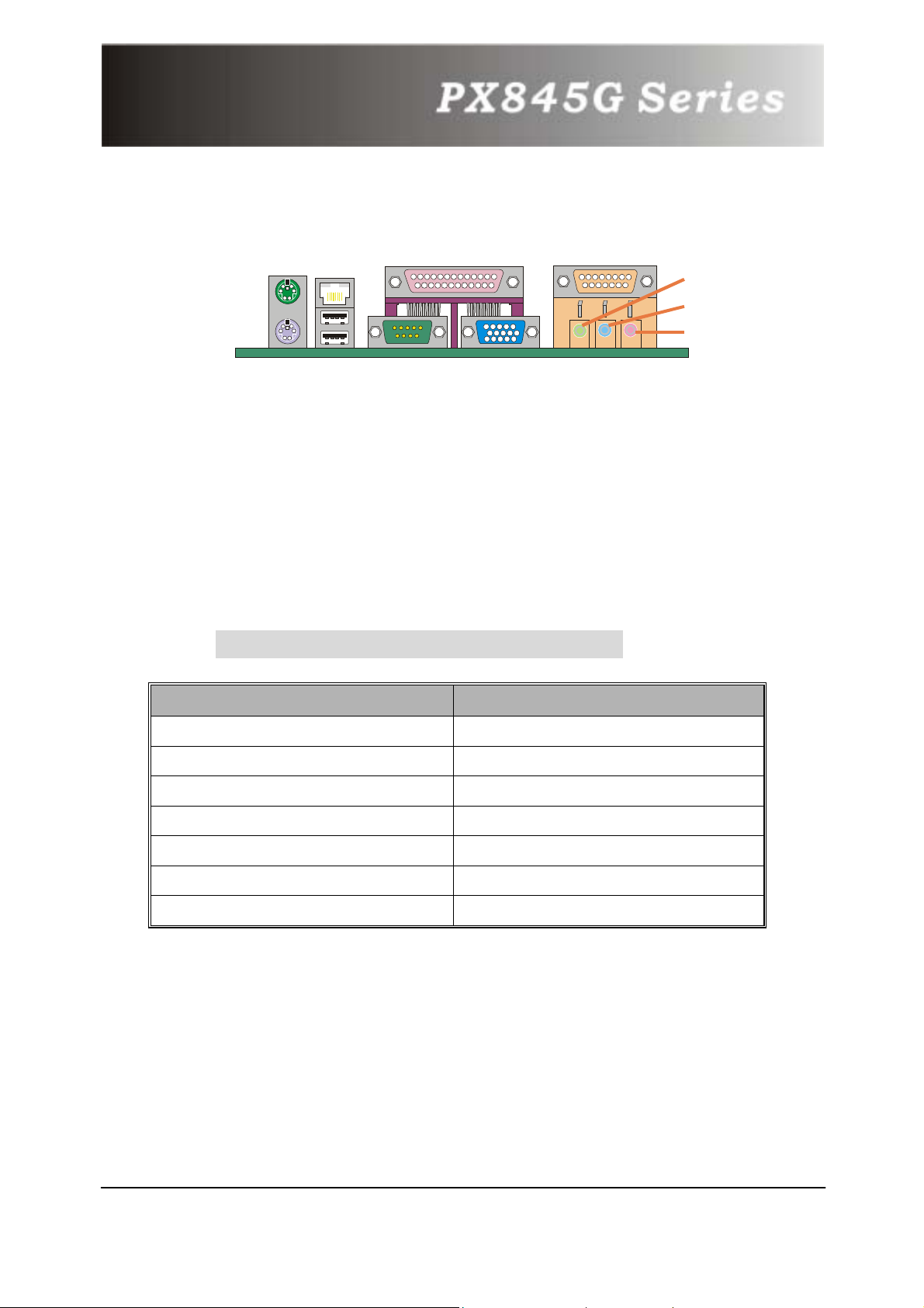
Chapter 6: Back Panel Features
PS/2 Mouse
LAN
Printer Port
PS/2 Keyboard
USB
*The LAN connector is only for PX845G PRO II.
COM1
6.1 PS/2 Mouse / Keyboard Connector:
KB/MS
The mainboard provides a standard PS/2 mouse / Keyboard mini
DIN connector for attaching a PS/2 mouse. You can plug a PS/2
mouse / Keyboard directly into this connector. The connector
location and pin definition are shown below:
PS/2 Mouse / Keyboard Connectors
Game Port
Speaker Out
Line In
Mic In
VGA
Pin Assignment
1 KBDATA
2, 6, 8, 12
3, 9, 13, 14, 15, 16, 17
4, 10
5 KBCLK
7
11
6.2 USB Connectors: USB
The mainboard provides a OHCI (Open Host Controller Interface)
Universal Serial Bus Roots for attaching USB devices such as:
keyboard, mouse and other USB devices. You can plug the USB
devices directly into this connector.
No Connected
GND
+5 V (fused)
MSDATA
MSCLK
25
Page 29
USB Connector (the below one)
Pin Assignment
1
2
3
4 GND
+5 V (fused)
USBP1-
USBP1+
USB Connector (the above one)
Pin
5
6
7 USBP0+
8
Assignment
+5 V (fused)
USBP0-
GND
6.3 Serial and Parallel Interface Ports
This system comes equipped with two serial ports and one
parallel port. Both types of interface ports will be explained in
this chapter.
The Serial Interface: COM1
The serial interface port is sometimes referred to as an RS-232
port or an asynchronous communication port. Mice, printers,
modems and other peripheral devices can be connected to a
serial port. The serial port can also be used to connect your
computer with another computer system.
26
Page 30
Parallel Interface Port: PRT
Unlike the serial ports, parallel interface port has been
standardized and should not present any difficulty interfacing
peripherals to your system. Sometimes called centronics port,
the parallel port is almost exclusively used with printers. The
parallel port on your system has a 25-pin, DB25 connector.
Video Graphics Array Connector: VGA
This mainboard has built in video facilities. Your monitor will
attach directly to VGA Connector on the mainboard.
6.4 Game Port Connector: SOUND
This connector allows you to connect a joystick or game pad for
playing computer games. Also, you may play or edit professional
music by connecting MIDI devices.
6.5 Audio Port Connectors
1. Speaker Out
2. Line In
devices for audio input. When 6 Channels mode for 5.1 speaker out be enabled,
you can change this function to Rear Speaker Out.
3. Mic In is used to connect a microphone that allows you to input sounds and
voices. When 6 Channels mode for 5.1 speaker out be enabled, you can
change this function to Center/Subwoofer Speaker out.
is used to connect speakers or headphones for audio output.
can be connected to the external CD player, Tape player or other audio
27
Page 31
Chapter 7: RAM Module Configuration
7.1 DDR DIMM
DDR SDRAM Access Time: 2.5V unbuffer non-ECC DDR 200/266
SDRAM required.
DDR SDRAM Type: 64Mb/ 128Mb/ 256Mb/ 512Mb/ 1GB DIMM
Module (184 pin).
7.2 DIMM Module Configuration
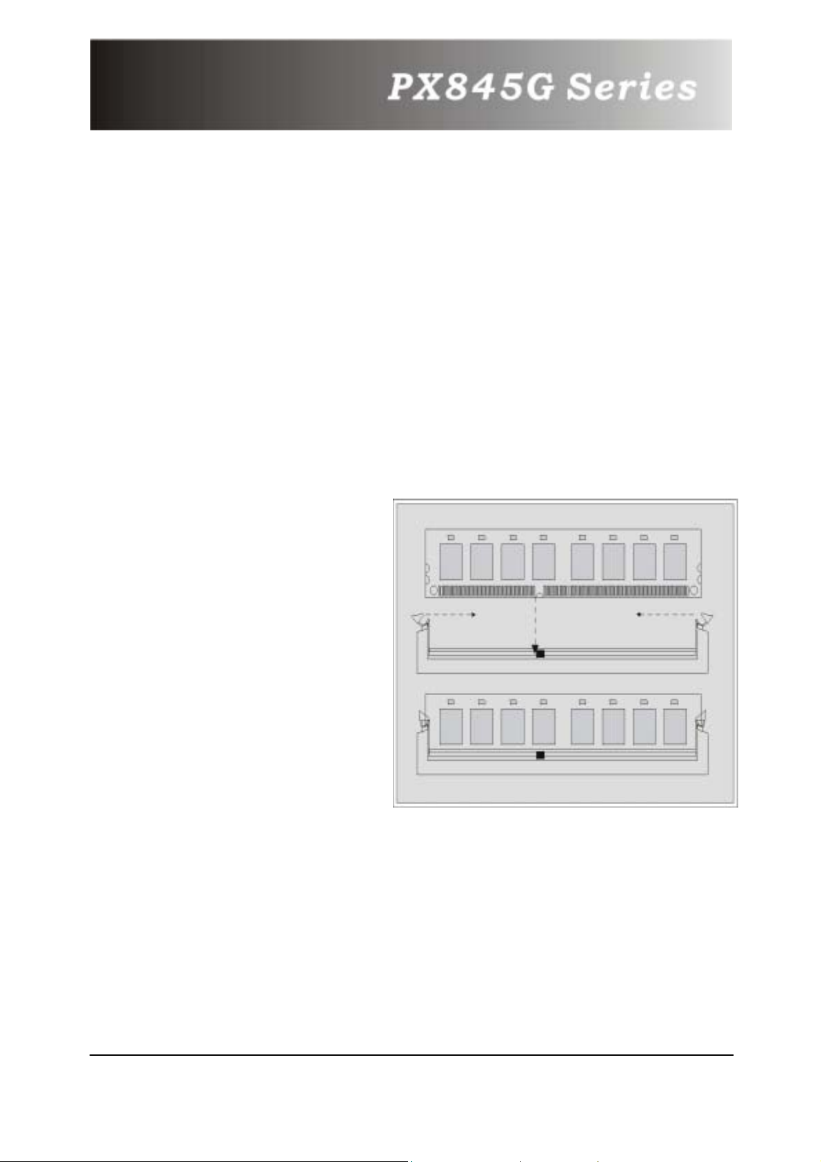
1. The DIMM socket has a
“Plastic Safety Tab” and the
DIMM memory module has an
asymmetrical notch”, so the
DIMM memory module can
only fit into the slot in one
direction.
2. Push the tabs out. Insert the
DIMM memory modules into
the socket at a 90-degree
angle then push down
vertically so that it will fit into
place.
3. The Mounting Holes and
plastic tabs should fit over the
edge and hold the DIMM
memory modules in place.
28
Page 32
Chapter 8: BIOS Setup
Introduction
This manual discussed PHOENIX-AWARD™ Setup program built into the
ROM BIOS. The Setup program allows users to modify the basic system
configuration. This special information is then stored in battery-backed
RAM so that it retains the Setup information when the power is turned off.
The PHOENIX-AWARD™ BIOS installed in your computer system’s ROM
(Read Only Memory) is a custom version of an industry standard BIOS.
This means that it supports Intel™ processors input/output system. The
BIOS provides critical low-level support for standard devices such as disk
drives and serial and parallel ports.
Adding important has customized the PHOENIX-AWARD™ BIOS, but
nonstandard, features such as virus and password protection as well as
special support for detailed fine-tuning of the chipset controlling the entire
system.
The rest of this manual is intended to guide you through the process of
configuring your system using Setup.
Plug and Play Support
These PHOENIX-AWARD™ BIOS supports the Plug and Play
Version 1.0A specification. ESCD (Extended System
Configuration Data) write is supported.
EPA Green PC Support
This PHOENIX-AWARD™ BIOS supports Version 1.03 of the EPA
Green PC specification.
APM Support
These PHOENIX-AWARD™ BIOS supports Version 1.1&1.2 of the
Advanced Power Management (APM) specification. Power
management features are implemented via the System
Management Interrupt (SMI). Sleep and Suspend power
management modes are supported. Power to the hard disk
drives and video monitors can be managed by this PHOENIXAWARD™ BIOS.
29
Page 33
PCI Bus Support
This PHOENIX-AWARD™ BIOS also supports Version 2.2 of the
Intel PCI (Peripheral Component Interconnect) local bus
specification.
DRAM Support
DDR (Double Data Rate) are supported.
Supported CPUs
This PHOENIX-AWARD™ BIOS supports the Pentium® 4 CPUs.
Key Function
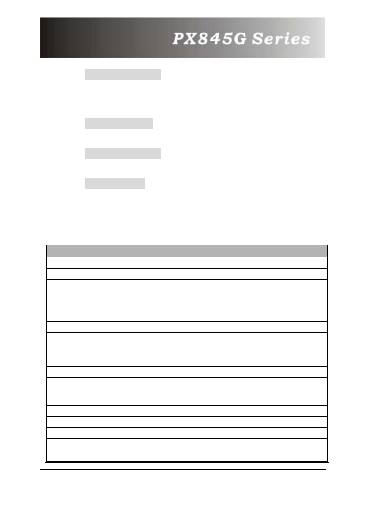
In general, you use the arrow keys to highlight items, press
<Enter> to select, use the <PgUp> and <PgDn> keys to
change entries, press <F1> for help and press <Esc> to quit.
The following table provides more detail about how to navigate
in the Setup program by using the keyboard.
Keystroke Function
Up arrow
Down arrow
Left arrow
Right arrow
Esc
Submenus: Exit Current page to the next higher level menu
Move Enter
PgUp key Increase the numeric value or make changes
PgDn key
+ Key Increase the numeric value or make changes
- Key
Esc key Main Menu – Quit and not save changes into CMOS
Status Page Setup Menu and Option Page Setup Menu –
F1 key
F5 key
Move to the item on the left (menu bar)
Move to the item on the right (menu bar)
Main Menu: Quit without saving changes
Decrease the numeric value or make changes
Decrease the numeric value or make changes
Exit Current page and return to Main Menu
General help on Setup navigation keys
Load previous values from CMOS
Move to previous item
Move to next item
Move to the item you desired
F6 key
F7 key
F10 key
Load the fail-safe defaults from BIOS default table
Load the optimized defaults
Save all the CMOS changes and exit
30
Page 34
8.1 Main Menu
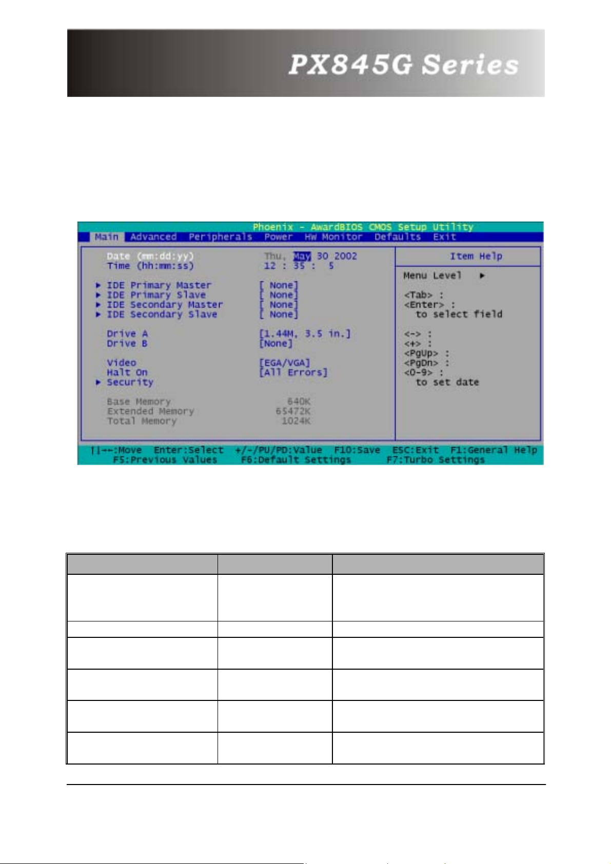
When you enter PHOENIX-AWARD™ BIOS CMOS Setup Utility, the
Main Menu will appear on the screen. The Main Menu allows you to
select from several setup functions. Use the arrow keys to select
among the items and press <Enter> to accept and enter the submenu.
Main Menu Setup Selections
The table shown below is the selections that you can make on
this Main Menu setup.
Item Options Description
Date mm:dd:yy
Time hh: mm: ss Set current time of the system.
IDE Primary Master
IDE Primary Slave
IDE Secondary Master
IDE Secondary Slave
Options are in its
sub menu.
Options are in its
sub menu.
Options are in its
sub menu.
Options are in its
sub menu.
Set system date. Note th at th e
‘Day’ automatically changes
when you set the date.
Press <Enter> to enter the
sub menu of detailed options.
Press <Enter> to enter the
sub menu of detailed options.
Press <Enter> to enter the
sub menu of detailed options.
Press <Enter> to enter the
sub menu of detailed options.
31
Page 35
Drive A
360K, 5.25 in
1.2M, 5.25 in
1.44M, 3.5 in
2.88M, 3.5 in
Drive B
EGA/VGA
Video
All Errors
No Errors
Halt On
All, but Keyboard
All, but Diskette
All, but Disk/ Key
Security
Options are in its
sub menu.
Base Memory N/A
Extended Memory N/A
Total Memory N/A
None
CGA 40
CGA 80
MONO
Select type of floppy disk drive
installed in your system.
Select default video device.
Select situation in which you
want the BIOS to stop the POST
process and notify you.
Press <Enter> to enter the
sub menu of detailed options.
Displays the amount of
conventional memory detected
during boot up.
Displays the amount of
extended memory detected
during boot up.
Displays the total memory
available in the system.
8.2 Advanced Features
Advanced Features
32
Page 36
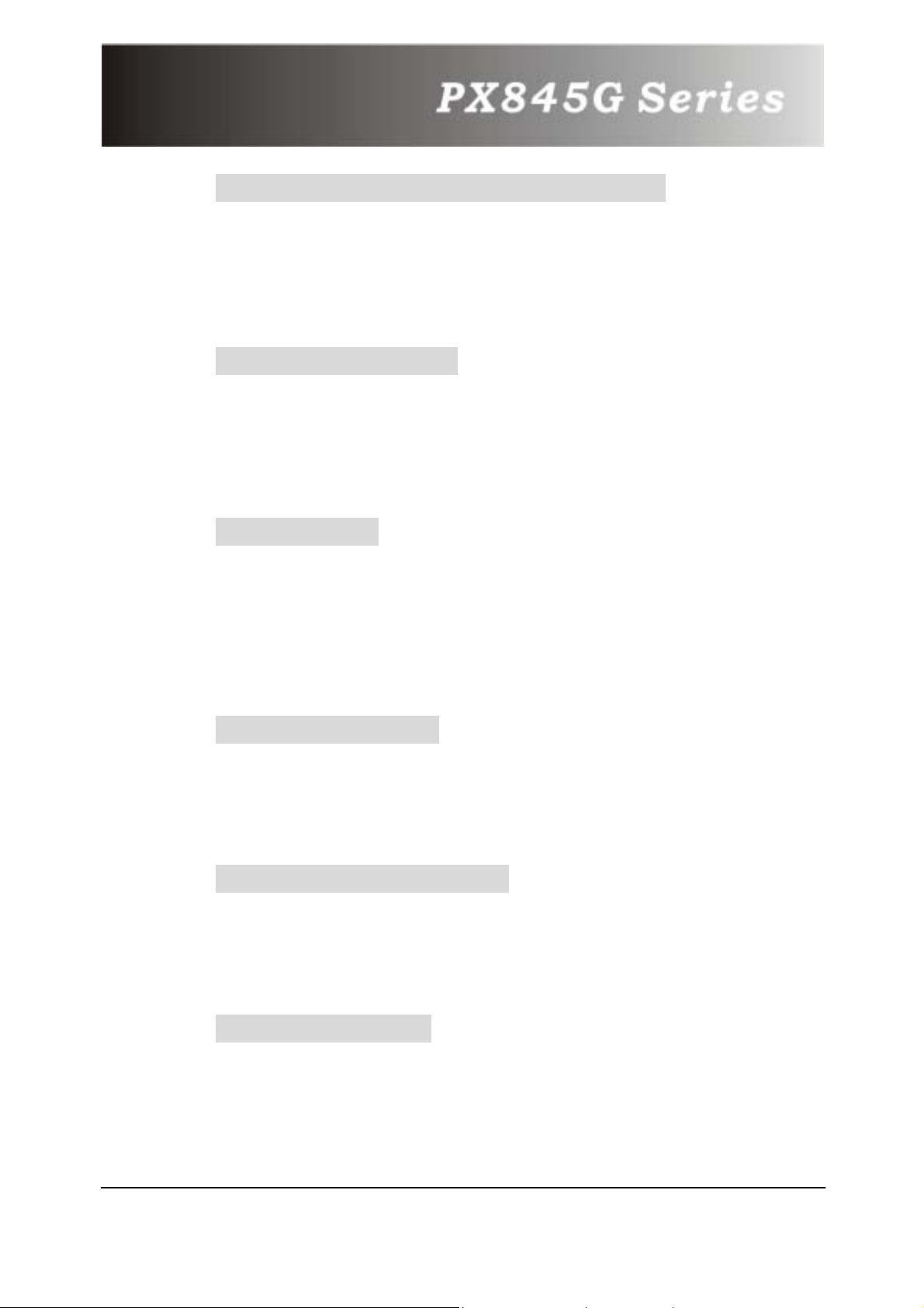
First/ Second/ Third/ Boot Other Device
These BIOS attempt to load the operating system from the
devices in the sequence selected in these items.
The Choices: Floppy, LS120, HDD-0, SCSI, CDROM, HDD-1,
HDD-2, HDD-3, ZIP100, USB-FDD, USB-ZIP, USB-CDROM, USBHDD, LAN, Disabled.
Boot Up Floppy Seek
Setting to Enabled will make BIOS seek floppy A before booting
the system.
The Choices: Enabled, Disabled (default).
Advanced BIOS Features
Virus Warning
This option allows you to choose the VIRUS warning feature for
IDE Hard Disk boot sector protection. If this function is enabled
and someone attempt to write data into this area, BIOS will
show a warning message on screen and alarm beep.
Disabled (default) Virus protection is disabled.
Enabled Virus protection is activated.
CPU L1 & L2 Cache
Make CPU internal cache active or inactive and system will slow
down if disabling this item.
Enabled (default) Enable cache.
Disabled Disable cache.
Quick Power On Self Test
Allow the system to skip certain tests while booting. This will
decrease the time needed to boot the system.
Enabled (default) Enable quick POST.
Disabled Normal POST.
Swap Floppy Drive
If the system has two floppy drives, choose enable to assign
physical drive B to logical drive A and vice-versa.
The Choices: Disabled (default), Enabled.
33
Page 37
Boot Up NumLock Status
Select power on state for NumLock.
On (default) Numpad is number keys.
Off Numpad is arrow keys.
Gate A20 Option
Fast - let chipset control GateA20 and Normal - a pin in the
keyboard controller controls GateA20.
Normal (default) A pin in the k eyboard controller controls
Gate A20.
Fast Let chipset control Gate A20.
Typematic Rate Setting
Keystrokes repeat at a rate determined by the keyboard
controller – when enabled, the typematic rate and typematic
delay can be selected.
Typematic Rate (Chars/Sec)
The rate at which character repeats when you hold down a key.
The Choices: 6 (default), 8,10,12,15,20,24,30.
Typematic Delay (Msec)
The delay before key strokes begin to repeat.
The Choices: 250 (default), 500,750,1000.
APIC Mode
Enabling this option, MPS version control for OS can be
configured.
The Choices: Disabled, Enabled (default).
MPS Version Control for OS
1.1 version is elder version, supports 8 more IRQ in Windows NT.
Choose the new 1.4 version for Windows 2000 and Windows XP.
The Choices: 1.1, 1.4 (default)
OS Select For DRAM > 64MB
Select OS2 only if you are running OS/2 operating system with
greater than 64MB of RAM on the system.
The Choices: Non-OS2 (default), OS2.
34
Page 38
HDD S.M.A.R.T. Capability
Self Monitoring Analysis and Reporting Technology is a
technology that en able s a PC to in some cases predict t he future
failure of storage drives.
The Choices: Disabled (default), Enabled.
Small LOGO (EPA) Show
This item allows you to show or hide the small LOGO of EPA.
The Choices: Disabled (default), Enabled.
Advanced Chipset Features
Dram Timing Selectable
Set the way to select the dram timing. Choose Manuel, the
following options become adjustable.
The Choices: Manuel, By SPD (default)
CAS Latency Time
This item determines CAS Latency. When synchronous DRAM is
installed, number of clock cycles of CAS latency depends on the
DRAM timing. Do not reset this field from the default value
specified by system designer.
The Choices: 1.5(default), 2, 2.5, 3.
Active to Precharge Delay/DRAM RAS # to CAS#
Delay/DRAM RAS # Precharge
These options depend on the SPD value of DIMM.
Refresh Mode Select
Select the refresh mode.
The Choices: 15.6 us, 7.8 us, 64 us, Auto.
Turbo Mode
Allow you to set the turbo mode.
The Choices: Disabled (default), Enabled.
Command Pre Clock
Set to optimal will enhance performance, but system might be
unsteady.
The Choices: Optimal, Auto (default).
35
Page 39
System BIOS Cacheable
When enabled, accesses to system BIOS ROM addressed at
F0000H-FFFFFH are cached, provided that the cache controller
is enabled.
The Choices: Enabled (default), Disabled.
Video BIOS Cacheable
Select Enabled allows caching of the video BIOS, resulting in
better system performance. However, if any program writes to
this memory area, a system error may result.
The Choices: Enabled, Disabled (default).
Memory Hole at 15M-16M
When enabled, you can reserve an area of system memory for
ISA adapter ROM. When this area is reserved, it cannot be
cached. Refer to the user documentation of the peripheral you
are installing for more information.
The Choices: Disabled (default), Enabled.
Delayed Transaction
Choose if let the transaction delayed or not.
The Choices: Disabled, Enabled (default).
Delay Prior to Thermal
Choose if let the transaction delayed or not.
The Choices: 4 Min, 8 Min, 16 Min (default), 32 Min
AGP Aperture Size
If you don’t connected to AGP Card, this item allows you to
setup the AGP Aperture Size.
The Choices: 4, 8, 16, 32, 64 (default), 128, 256.
On-Chip VGA
This item allows you to enable or disable the on-chip VGA.
The Choices: Disabled, Enabled (default).
On-Chip Frame Buffer Size
Choose the size of the on-chip frame buffer.
The Choices: 1MB, 8MB(default).
36
Page 40
PnP/PCI Configurations
Reset Configuration Data
Default is Disabled. Select Enabled to reset Extended System
Configuration Data ESCD) when you exit Setup if you have
installed a new add-on and the system reconfiguration has
caused such a serious conflict that the OS cannot boot.
Resources Controlled By
BIOS can automatically configure all the boot and Plug and Play
compatible devices. If you choose Auto, you cannot select IRQ
DMA and memory base address fields, since BIOS automatically
assigns them.
IRQ Resources
When resources are controlled manually, assign each system
interrupt a type, depending on the type of device using the
interrupt. This is only configurable when “Resources Controlled
By” is set to “Manual”.
IRQ-3 assigned to: PCI device
IRQ-4 assigned to: PCI device
IRQ-5 assigned to: PCI device
IRQ-7 assigned to: PCI device
IRQ-9 assigned to: PCI device
IRQ-10 assigned to: PCI device
IRQ-11 assigned to: PCI device
IRQ-12 assigned to: PCI device
IRQ-14 assigned to: PCI device
IRQ-15 assigned to: PCI device
PCI / VGA Palette Snoop
Some graphic controllers that are not VGA compatible take the
output from a VGA controller and map it to their display as a
way to provide boot information and VGA compatibility.
Disabled (default) Disable the function.
Enabled Enable the function.
PCI Latency Timer (CLK)
This item allows you to set the PCI Latency Time (0-255) and
when you select 32 PCI Clock, it makes the PCI Speed fastest.
The Choices: 0-255, 32 (default)
37
Page 41
Frequency/Voltage Control
CPU Voltage (Volt)
This item allows you to adjust CPU voltage, from 1.100~1.850.
CPU Clock Ratio
This item, which shows only the CPU frequency is locked, allows
you to adjust the CPU Ratio. The default is 8 X.
Spread Spectrum
This item allows you to enable/disable the Spread Spectrum
function.
CPU HOST Frequency (MHz)
This item allows you to select CPU Clock from 100 to 248. The
default depends on CPU frequency. This item is for over-clocking.
Only if you over-clock it, the following 3 items can be adjusted.
Fixed AGP/PCI Output Freq
This item allows you to select Fixed AGP/PCI Clock, so that the
AGP/PCI Frequency cannot be adjusted.
Choices: Disabled (default), 66MHz/33MHz.
CPU:AGP Clock Ratio
This item allows you to adjust your CPU:AGP Clock Ratio. The
result shows at the AGP/PCI Frequency.
Choices: Auto (default), 1.5X, 2.0X, 2.5X.
DDR:CPU Ratio
This item allows you to adjust your DRAM:CPU Ratio.
Choices: Auto (default), 2.00X, 2.66X.
AGP Voltage (Volt)
This item allows you to adjust your AGP voltage.
Choices: 1.5 V (default), 1.6V.
DDR Voltage (Volt)
This item allows you to adjust your RAM voltage.
Choices: 2.5 V (default), 2.6 V, 2.7 V, 2.8 V.
38
Page 42
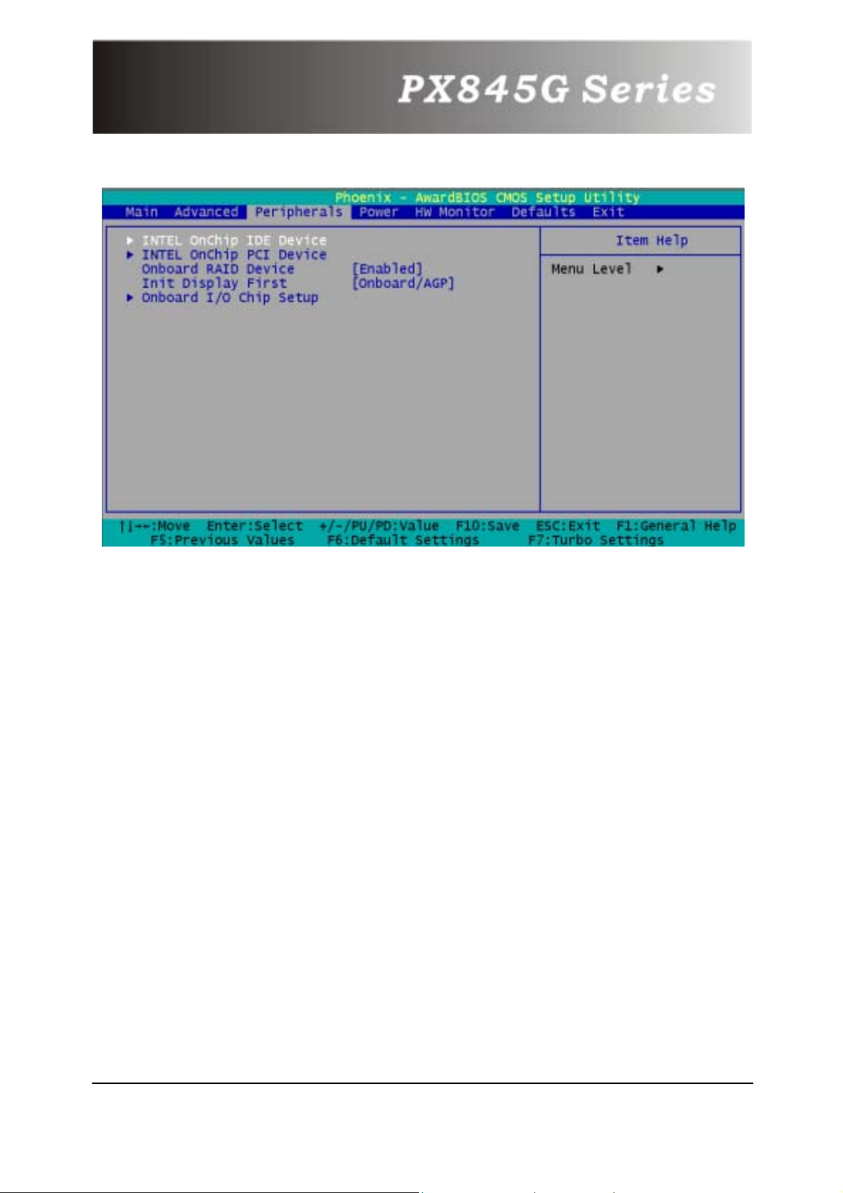
8.3 Peripherals
INTEL OnChip IDE Device
If you highlight the literal “Press Enter” next to the “INTEL
OnChip IDE Device” label and then press the enter key, it will
take you a submenu with the following options:
IDE Primary / Secondary /Master / Slave PIO
The IDE PIO (Programmed Input / Output) fields let you set a
PIO mode (0-4) for each of the IDE devices that the onboard
IDE interface supports. Modes 0 to 4 will increase performance
progressively. In Auto mode, the system automatically
determines the best mode for each device.
The Choices: Auto (default), Mode0, Mode1, Mode2, Mode3,
Mode4.
Primary / Secondary /Master / Slave Ultra DMA
Ultra DMA functionality can be implemented if it is supported by
the IDE hard drives in your system. As well, your operating
environment requires a DMA driver (Windows 95 OSR2 or a
third party IDE bus master driver). If your hard drive and your
system software both support Ultra DMA/100, select Auto to
enable BIOS support.
The Choices: Auto (default), Disabled.
39
Page 43
On-Chip Primary / Secondary PCI IDE
This item allows you to enable / disable the on-chip primary /
secondary PCI IDE.
IDE HDD Block Mode
Block mode is otherwise known as block transfer, multiple
commands, or multiple sector read/write. Select the “Enabled”
option if your IDE hard drive supports block mode (most new
drives do). The system will automatically determine the optimal
number of blocks to read and write per sector.
The Choices: Enabled (default), Disabled.
INTEL OnChip PCI Device
If you highlight the literal “Press Enter” next to the “Intel OnChip PCI Device” label and then press the enter key, it will take
you a submenu with the following options:
USB Controller
This option should be enabled if your system has a USB installed
on the system board. You will need to disable t his feature if you
add a higher performance controller.
USB Keyboard Support
Enables support for USB attached keyboards.
Onboard Audio codec
This option allows you to enable (default) / disable the onboard
Audio codec.
AC97 Audio / AC97 Modem
This option allows you to control the onboard AC97 audio
/modem. The Choices: Auto (default), Disabled.
Onboard LAN Device
This option allows you to enable (default) / disable the onboard
LAN Device.
40
Page 44
Onboard RAID Device
This option allows you to enable (default) / disable the onboard
RAID Device.
Init Display First
With systems that have multiple video cards, this option
determines whether the primary display uses a PCI Slot or
onboard/AGP. The Choices: PCI Slot, Onboard/AGP (default).
Onboard I/O Chip Setup
Power On Function
This option allows you to select how to power on your computer.
Choices: Password, Hot KEY, Mouse Left, Mouse Right, Any KEY,
BUTTON ONLY, and Keyboard 98
KB Power ON Password
Fill the password in the blank.
HOT Key Power ON
Choices: Ctrl – F1, Ctrl – F2, Ctrl – F3, … to Ctrl – F12.
Onboard FDC Controller
Choices: Enabled, 3F8/IRQ4, 2F8/IRQ3.
Onboard Serial Port 1
Select an address and corresponding interrupt for the first serial
ports. The Choices: Disabled, 3F8/IRQ4 (default), 2F8/IRQ3,
3E8/IRQ4, 2E8/IRQ3, Auto.
Onboard Serial Port 2
Select an address and corresponding interrupt for the second
serial ports.
The Choices: Disabled, 2F8/IRQ3 (default), 3F8/IRQ4, 3E8/IRQ4,
2E8/IRQ3, Auto.
UART Mode Select
This item allows you to determine which Infra Red (IR) function
of onboard I/O chip.
The Choices: IrDA, ASKIR, Normal (default).
41
Page 45
RxD, TxD Active
This item allows you to determine which Infrared (IR) function
of onboard I/O chip.
The Choices: Hi / Lo (default), Hi / Hi, Lo / Hi, Lo / Lo.
IR Transmission Delay
This item allows you to enable/disable IR transmission delay.
UR2 Duplex Mode
Select the value required by the IR device connected to the IR
port. Full-duplex mode permits simultaneous two-direction
transmission. Half-duplex mode permits transmission in one
direction only at a time. The Choices: Half (default), Full.
Use IR Pins
Select one of the two options to function.
Choices: RxD2.Txd2, IR-Rx2Tx2 (default).
Onboard Parallel Port
This item allows you to determine access onboard parallel port
controller with which I/O Address.
The Choices: Disabled, 378/IRQ7 (default), 278/IRQ5, 3BC/IRQ7.
Parallel Port Mode
The default value is ECP. ECP means that using Parallel port as
Extended Capabilities Port.
EPP Using Parallel Port as Enhanced Parallel Port.
SPP Using Parallel port as Standard Printer Port.
ECP+EPP Using Parallel port as ECP & EPP mode.
EPP Mode Select
Select EPP port type 1.7 or 1.9 (default).
ECP Mode Use DMA
Select a DMA Channel for the port. The Choices: 3 (default), 1.
PWRON After PWR-Fail
Set if restart the system after power fail. Choose On, the system
will start whether the system was on before power failed.
Choose Former-Sts, the system will restore to the stat us before
the power failed. The Choices: Off (default), On, Former-Sts.
Game Port Address
Set the Game Port I/O Address.
The Choices: Disabled, 201 (default), 209.
42
Page 46
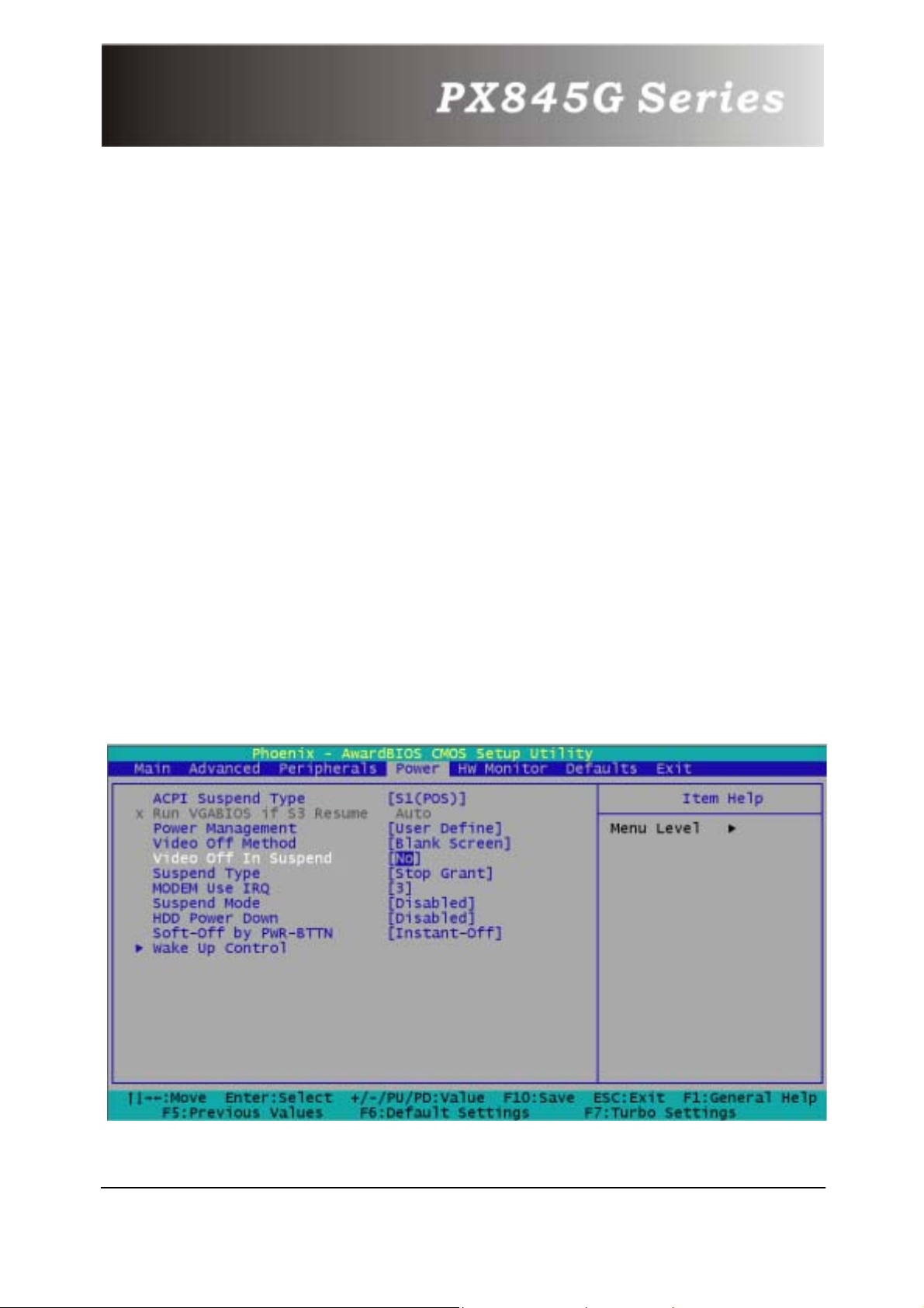
Midi Port Address
Set Midi Port Base I/O Address.
The Choices: Disabled, 330 (default), 300, 290.
Midi Port IRQ
This determines the IRQ in which the Midi Port can use.
The Choices: 5, 10(default).
SCR Port Address
Set the smart card address.
The Choices: Disabled, 800(default), 700, 248, 240.
SCR Port IRQ
Set the smart card IRQ. The Choices: 5 (default), 3, 4, 11.
MS Port Address
Set the memory stick address.
The Choices: Disabled (default), 240, 248, 700, 800.
MS Port IRQ
Set the memory stick IRQ.
The Choices: 11 (default), 5, 3, 4.
8.4 Power Menu
43
Page 47
The Power Management Setup Menu allows you to configure
your system to utilize energy conservation and power up/power
down features.
ACPI Suspend Type
The item allows you to select the suspend type under the ACPI
operating system.
The Choices: S1 (POS) (default) Power on Suspend
S3 (STR) Suspend to RAM
S1 & S3 POS+STR
Run VGA BIOS if S3 Resume
Set whether you want to run VGA BIOS when the system wakes
up from S3.
The Choices: Auto, yes, no.
Power Management
This category allows you to select the type (or degree) of power
saving and is directly related to the following modes:
User Defined (default)
Allow you to set each mode individually.
When not disabled, each of the ranges is from 1 min. to 1 hr.
Min. Saving
Minimum power management.
Suspend Mode = 1 hr.
Max. Saving
Maximum power management only available for sl CPU’s.
Suspend Mode = 1 min.
Video Off Method
This option determines the manner in which the monitor is goes
blank.
44
Page 48
The Choices:
V/H SYNC+Blank
This selection will cause the system to turn off the vertical and
horizontal synchronization ports and write blanks to the video
buffer.
Blank Screen (default)
This option only writes blanks to the video buffer.
DPMS Support
Initial display power management signaling.
Video Off In Suspend
Set if the monitor will be on when the system suspend.
Choices: No (default), yes.
Suspend Type
The item allows you to select the suspend type under ACPI
operating system.
The Choices: Stop grant (default), PWROn Suspend.
Modem Use IRQ
This determines the IRQ, which can be applied in MODEM use.
The Choices: NA, 3 (default), 4, 5, 7, 9, 10, 11.
Suspend Mode
The item allows you to select the suspend type under ACPI
operating system.
The Choices: Disabled (default), 1 Min, 2 Min, 4 Min, 6 Min, 8
Min, 10 Min, 20 Min, 30 Min, 40 Min, 1 Hour.
HDD Power Down
This item allows you to adjust the time for HDD Off.
The Choices: Disabled (default), 1Min ~ 15Min.
45
Page 49
Software-Off by PWR-BTTN
When you select Enabled, pressing the power button for more
than 4 seconds forces the system to enter the Soft-Off state
when the system has “hung.”
The Choices: Instant Off (default), Delay 4 Sec.
Wake Up Control
If you highlight the literal “Press Enter” next to the “Wake Up
Control” label and then press the enter key, it will take you a
submenu with the following options:
PCI PME Wake Up
This item allows you to control the PCI PME Wake Up.
The Choices: Disabled (default), Enabled.
RTC Wake Up
When “Enabled”, you can set the date and time at which the
RTC (real-time clock) alarm awakens the system from Suspend
mode. The Choices: Enabled, Disabled (default).
Day (of Month) Alarm
Select a date of month. Set 0 if you prefer to set a weekly alarm.
Time (hh:mm:ss) Alarm
Set the time you want the alarm to go off.
USB KB Wake Up From S3
This item allows you to select USB devices to awake the system
from suspend mode.
LAN Wake up
This item allows you to select LAN devices to awaken the
system from suspend mode.
Ring Wake up
This item allows you to select modem devices to awaken the
system from suspend mode.
46
Page 50
Reload Global Timer Events
The events can prevent the system from entering a power
saving mode or can awaken the system from such a mode. In
effect, the system remains alert for anything , which occurs to a
device, which is configured as Enabled, even when it is in a
power down mode.
Primary/Secondary IDE / FDD, COM, LPT Port / PCI
PIRQ [A-D]#
The Choices: Enabled, Disabled (default).
8.5 HW Monitoring
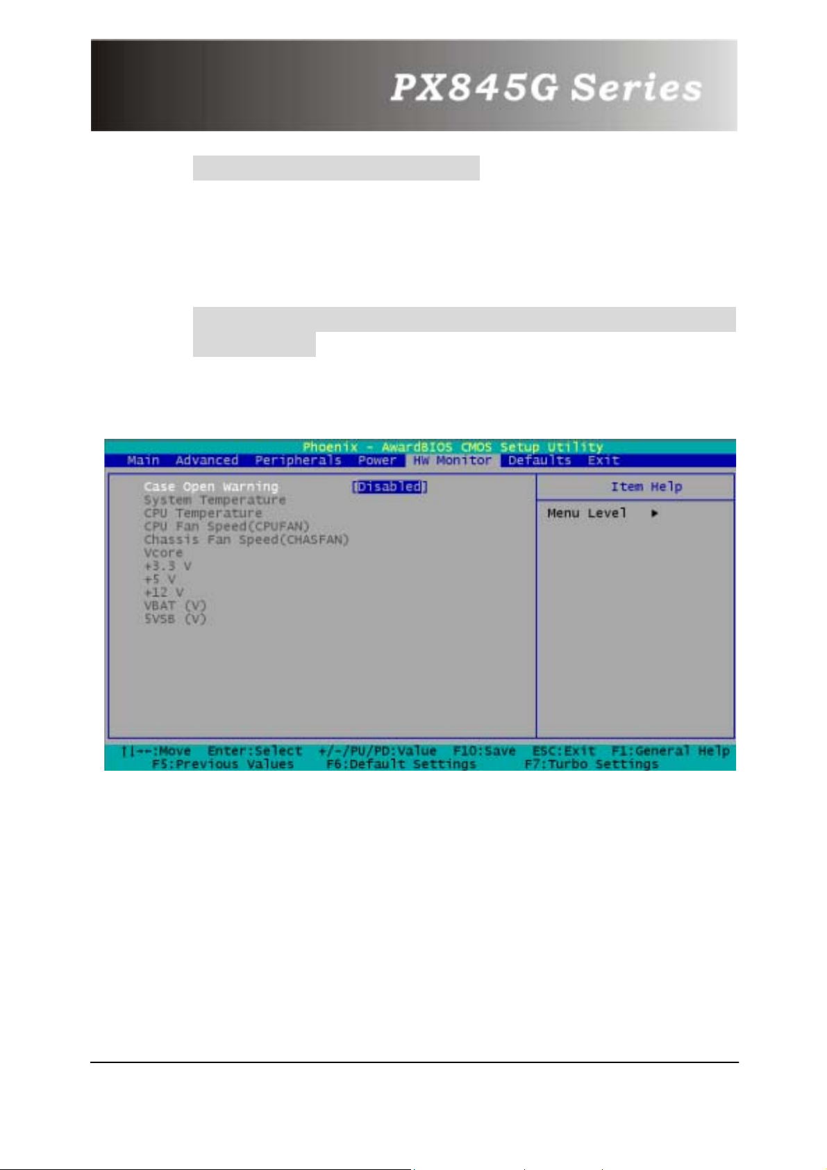
Case Open Warning
If this function is set to “Enabled” and someone open the case,
the system will automatically show alert messages on the screen
when you power on your computer. On the contrary, if this
function is disabled, the system will not show alert messages
when you power on your computer even if the case is opened.
The Choices: Disabled (default), Enabled.
47
Page 51
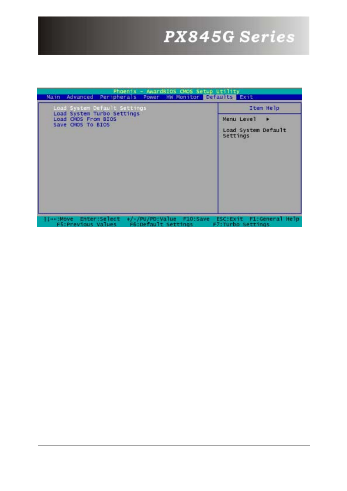
8.6 Defaults
Load System Default Settings
Use this menu to load the BIOS default values for the
minimal/stable performance for your system to operate.
Load System Turbo Settings
This selection allows you to use the best settings for your
system.
Load CMOS From BIOS
With this function, you can load defaults from flash ROM for
battery less or power shortage.
Save CMOS To BIOS
With this function, you can save defaults from flash ROM to
battery less or power shortage.
48
Page 52
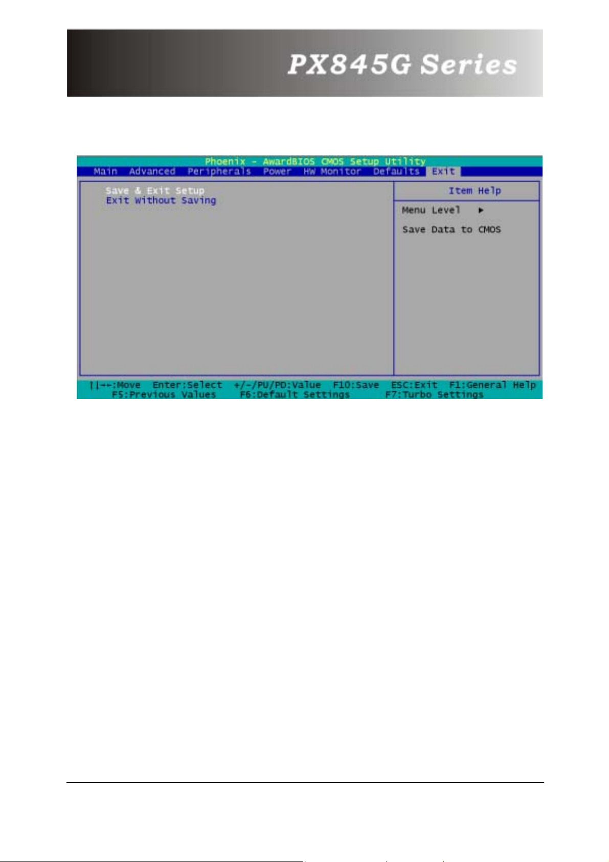
8.7 Exit Menu
Save & Exit Setup
Save all configuration changes to CMOS(memory) and exit setup.
Confirmation message will be displayed before proceeding.
Exit Without Saving
Abandon all changes made during the current session and exit
setup. Confirmation message will be displayed before
proceeding.
49
Page 53
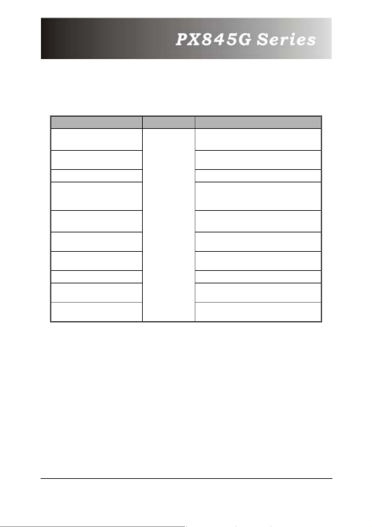
Chapter 9: Software Setup
9.1 Software List
Category Platform Loca tion in CD
Intel Onboard
Audio Driver
Promise RAID Driver
Onboard LAN Driver
Smart Card &
Memory Stick Driver
WinXP USB Wake
from S3 Driver
Intel Inf Driver
Intel IDE tool
BIOS files
PC-cillin 2002
Acrobat Reader
Windows
/9X
/2000
/XP
/ME
\Intel\Driver\Audio
\Realtec\a3.13_alc650\
\Intel\Driver\Promise
\Pdc20276\2.00.1240B26
\Intel\Driver\Intel\Lan\v6.2
\Intel\Driver\
\Smart Card&Memory Stick
\Winbond\R1.01
\Intel\Driver
\WinXP USB Wake from S3
\Intel\Driver\Intel
\Inf\V4.00.1011
\Intel\Driver\Intel
\Iaa\2.2.0.2128
\Intel\BIOS\
\Intel\UTILITY
\PC-Cillin2002
\Intel\UTILITY
\PC-Cillin2002\Acrobat
50
Page 54

9.2 Software Installation
Simply put Driver CD into CD-ROM drive and the Installation Utility
will auto-run or you can launch the Driver CD Installation Utility
manually. The steps shown below are for reference:
1. Once the Driver CD auto-runs, you will see the screen at
first, there are three buttons optional.
2. Click
see the screen like the picture below.
on the first picture, and then you can
51
Page 55
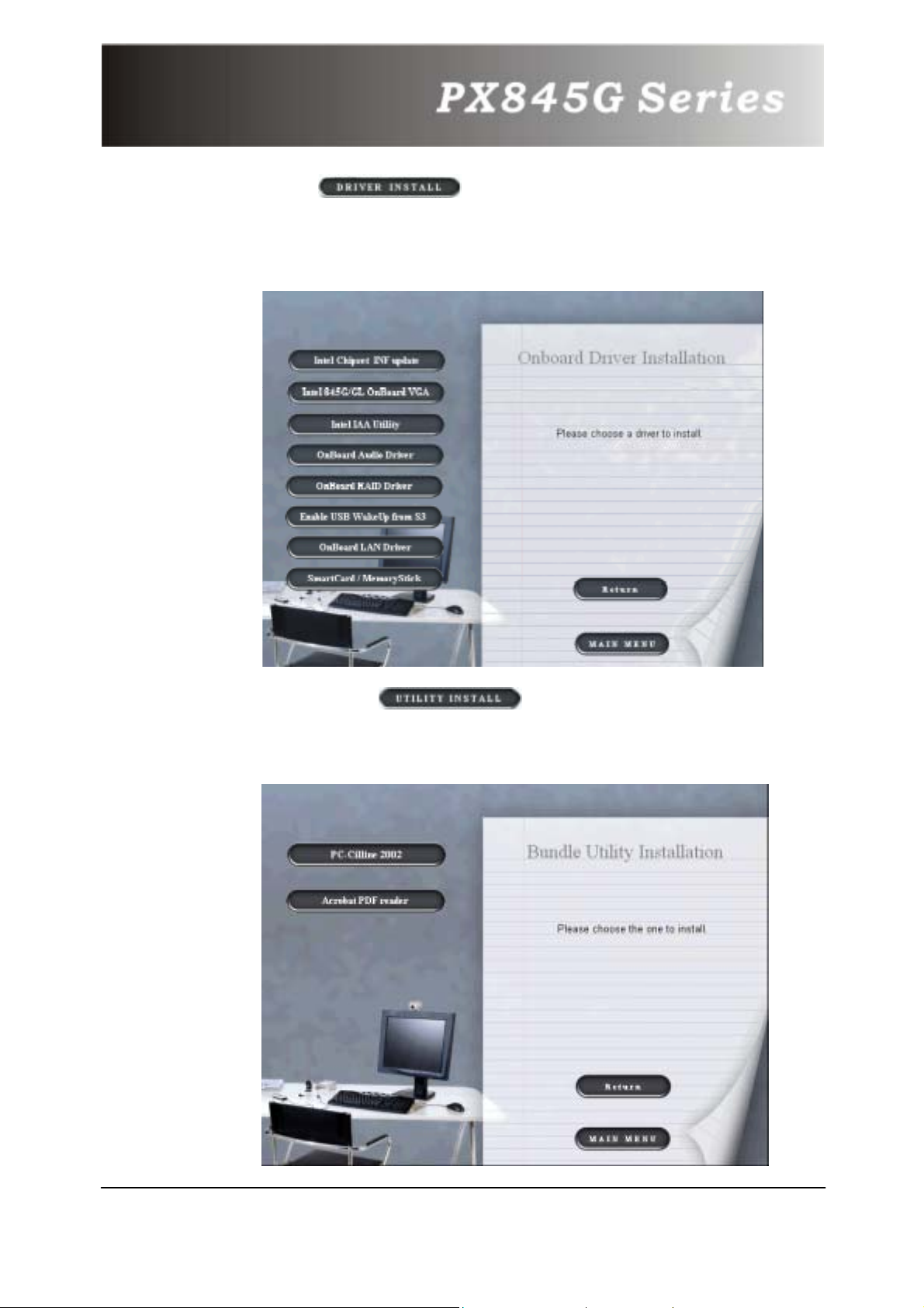
3. Click on the second picture, you can choose
to install the drivers of AGP, AUDIO, RAID, LAN, Smart Card,
Memory Stick and IDE busmaster. Click the driver you need
to install.
4. By clicking
have two programs to choose and install. Follow the
description after clicking the button.
on the second picture, you will
52
Page 56
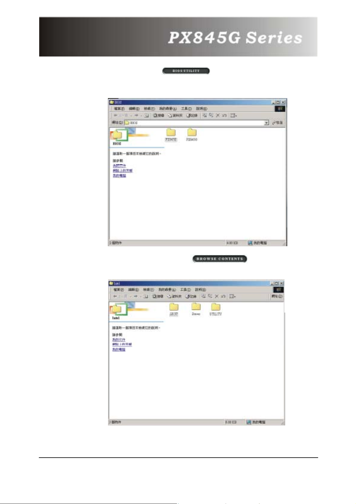
5. If you click the button on the first page, you
will see this screen. To repair bios, if you need to, the files
are in this folder.
6. Clicking the third button
the files in the Drive CD.
, we can browse all
53
Page 57
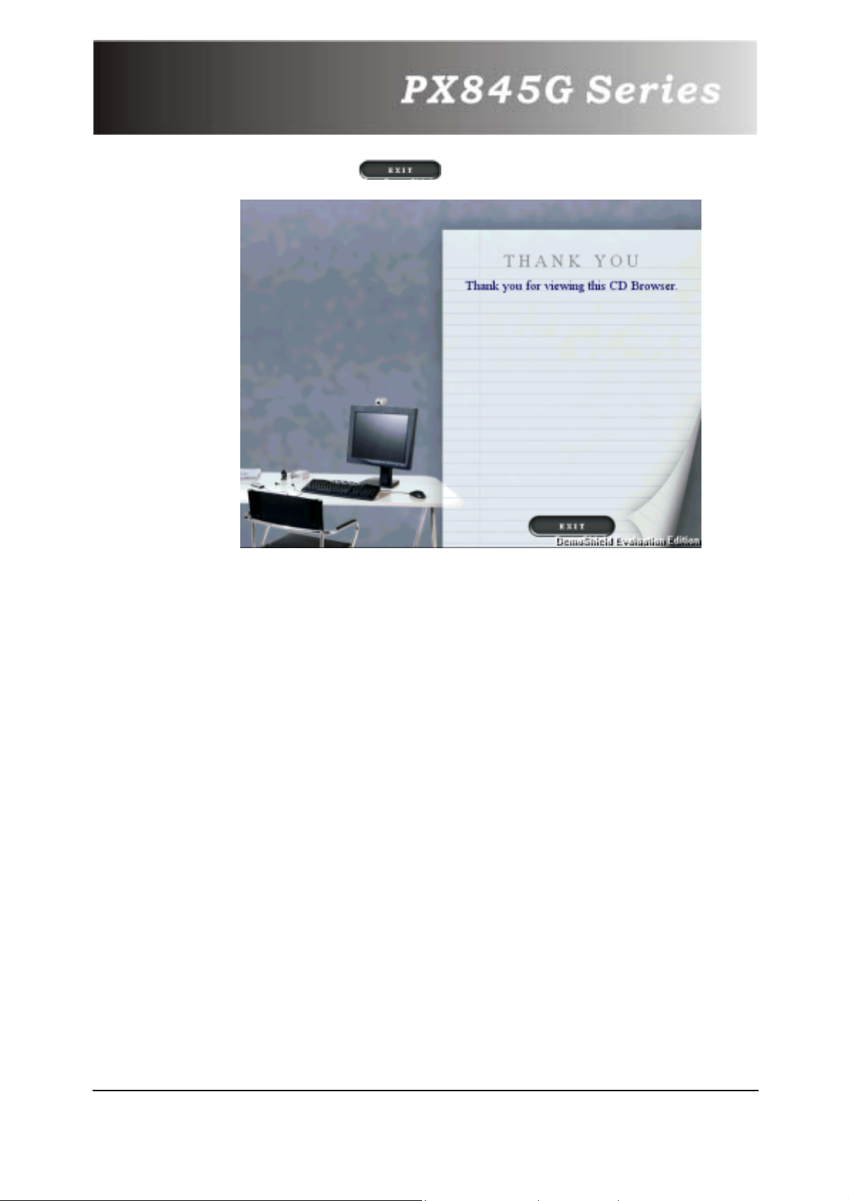
7. You can click to finish using the Drive CD.
54
Page 58
Chapter 10: Troubleshooting
Problem 1:
No power to the system at all. Power light does not
illuminate, fan inside power supply does not turn on.
Indicator light on keyboard does not turn on.
Causes:
1. Power cable is unplugged.
2. Defective power cable.
3. Power supply failure.
4. Faulty wall outlet; circuit b reaker or fuse blown.
Solutions:
1. Make sure power cable is securely plugged in.
2. Replace cable.
3. Contact technical support.
4. Use a different socket, repair outlet, reset circuit breaker or
replace fuse.
Problem 2:
System inoperative. Keyboard lights are on, power indicator
lights are lit, and hard drive is spinning.
Causes:
Memory DIMM is partially dislodged from the slot on the
mainboard.
Solutions:
Using even pressure on both ends of the DIMM, press down
firmly until the module snaps into place.
55
Page 59
Problem 3:
System does not boot from hard disk drive, can be booted
from CD-ROM drive.
Causes:
1. Connector between hard drive and system board unplugged.
2. Damaged hard disk or disk controller.
3. Hard disk directory or FAT is scrambled.
Solutions:
1. Check cable running from disk to disk controller board. Make
sure both ends are securely plugged in; check the drive type
in the standard CMOS setup.
2. Contact technical support.
3. Backing up the hard drive is extremely important. All hard
disks are capable of breaking down at any time.
Problem 4:
System only boots from CD-ROM. Hard disk can be read and
applications can be used but booting from hard disk is
impossible.
Cause:
Hard Disk boot program has been destroyed.
Solution:
Back up data and applications files. Reformat the hard drive.
Re-install applications and data using backup disks.
56
Page 60

Problem 5:
Error message reading “SECTOR NOT FOUND” or other error
messages not allowing certain data to be retrieved.
Cause:
A number of causes could be behind this.
Solution:
Back up any salvageable data. Then low-level format, partition,
and high-level format the hard drive. Re-install all saved data
when completed.
Problem 6:
Screen message says “Invalid Configuration” or “CMOS
Failure.”
Cause:
Incorrect information entered into the configuration (setup)
program.
Solution:
Review the equipment of your system. Make sure correct
information is in setup.
Problem 7:
The Screen is blank.
Cause:
No power to monitor.
Solution:
Check the power connectors to monitor and to system.
57
Page 61
Problem 8:
No screen.
Causes:
1. Memory problem.
2. Computer virus.
Solutions:
1. Reboot your computer. Reinstall the memory, make sure that
all memory modules are installed in correct sockets.
2. Use anti-virus programs to detect and clean viruses.
Problem 9:
Screen goes blank periodically.
Cause:
Screen saver is enabled.
Solution:
Disable screen saver.
Problem 10:
Keyboard failure.
Cause:
Keyboard is disconnected.
Solution:
Reconnect keyboard. Check keys again, if no improvement,
replace keyboard.
58
Page 62
Problem 11:
No color on screen.
Causes:
1. Faulty Monitor.
2. CMOS incorrectly set up.
Solutions:
1. If possible, connect monitor to another system. If still no
color, replace the monitor.
2. Call technical support.
Problem 12:
The screen shows “C: drive failure.”
Cause:
Hard drive cable not connected properly.
Solution:
Check the hard drive cable.
Problem 13:
Cannot boot system after installing second hard drive.
Causes:
1. Master/slave jumpers not set correctly.
2. Hard drives not compatible / different manufacturers.
Solutions:
1. Set master/slave jumpers correctly.
2. Run SETUP program and select correct drive types. You’re
your drive manufacturers for compatibility with other drives.
59
Page 63
Problem 14:
Missing operating system on hard drive.
Cause:
CMOS setup has been changed.
Solution:
Run setup and select correct drive type.
Problem 15:
Certain keys do not function.
Cause:
Keys jammed or defective.
Solution:
Replace keyboard.
§
I f you still require assistance after reading this section, please
contact your local distributer for more technical support.
60
 Loading...