


Flanger 4 Plus
Deployment Guide
Part Number: 9100-7000
Revision 081512
For Build 50509 and later

2
For Build 050109 and later
Packing List
Two Flanger 4 Plus Units
Two Flanger 4 Plus Power Supplies
Two Flanger 4 Plus Power Supply Line Cords
Two Power Blockers
Deployment Guide
Flanger 4 Plus units require customer supplied cables to
connect external Ethernet and DS1.
Product Support
We suggest you take the following steps in the order given to obtain the
quickest and highest quality support and service you need.
1. Contact the support staff of our Partner from whom you originally
bought our equipment for more information as well as any updates.
Identifying your Flanger4Plus
A product label at located on the bottom of the unit. The label identifies the
Flanger 4 Plus model, Firmware Revision, and serial number.
Note: View the main page of the Web site or use the telnet ‘version’
command to identify the build version Flanger 4 Plus is running.

For Build 050109 and later
3
Ethernet and the Power Supply
Flanger4Plus uses Power over CAT5 to supply power to the Flanger4Plus
and WAN-connected equipment such as a wireless broadband modem.
WAN Port Power Out: Wires 4, 5, 7 and 8 are carrying power from
the Flanger4Plus to power the radio.
LAN Port No Power: The LAN port is a standard 10/100 ethernet
port.
Local Port Power In: Wires 4, 5, 7 and 8 are carrying power from
the power supply to power the Flanger4Plus. Observe
the warning tag on the power supply when connecting.
Equipment connected to the WAN port WILL BE
damaged if the device does not support Power over
CAT5. Use the supplied power blocker or custom cables
to prevent trouble!
L’`equippement connecte` `a la prise? Wan sera
endommag`e si le dispositif
Ne tol`ere POWER sur CAT5. Employez le bloque
courent fourni ou les cables particuliers pour prevenir
des probl`emes.
The supplied power blocker is a CAT5 coupler that has the internal wires
connecting pins 4, 5, 7 and 8 omitted, blocking power.

4
For Build 050109 and later
Understanding the Front Panel
The front panel has a single status indicator.
The status indicator LED is used to display the overall condition of the
Flanger4Plus unit as follows:
Front Panel LED Meaning
Blinking Orange WAN Link down
Alternating Orange and Red Partner not found
Alternating Orange and
Green
Loopback Restore completed
Solid Green Very Good to Excellent System
Performance
Blinking Green Acceptable to Good System Performance
Alternating Red and Green Poor System Performance
Blinking Red Very Poor System Performance
Solid Red Hardware Fault
Off No Power

For Build 050109 and later
5
Understanding the Back Panel
The back panel has seven connectors, each containing two status indicators.
WAN
(Power Out)
Connects the Flanger4Plus to the dedicated network used
for communication between a pair of Flanger4Plus units.
LINK – Link is present. Blink indicates activity.
100 – Ethernet port operating speed. OFF indicates 10
MB, ON indicates 100 Mb.
LAN
Allows a locally connected PC to access the Flanger 4Plus
and connected equipment. It is possible that large amounts
of traffic through this port can interfere with proper
operation.
LINK – Link is present. Blink indicates activity.
100 – Ethernet port operating speed. OFF indicates 10
MB, ON indicates 100 Mb.
DS1 Up to four DS1 lines may be connected to these ports. Note
that there may be unused ports for your configuration.
LINK – Lit when a DS1 signal is present and the port is
enabled.
ACTIVITY – Blinks when there is activity on the DS1
line.
Local
(Power In)
Connects Flanger4Plus to a local area network via the
Flanger4Plus power supply.
LINK – Link is present. Blink indicates activity.
100 – Ethernet port operating speed. OFF indicates 10
MB, ON indicates 100 Mb.

6
For Build 050109 and later
Making Connections
1. Locate each Flanger4Plus unit in an area where AC power,
Ethernet connection to the external dedicated wide area network
(WAN), and the local equipment DS1 connections are all
available.
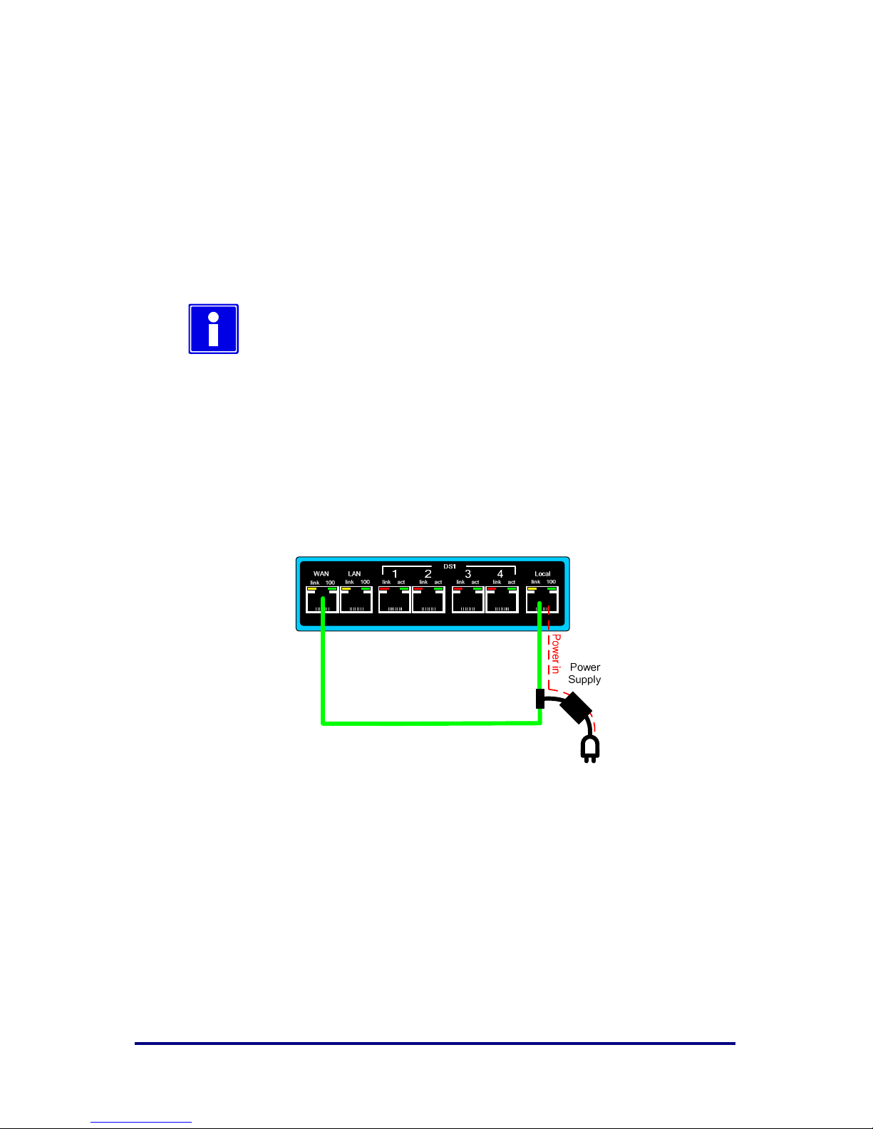
2. Use a CAT5 ethernet cable (blue shown) and connect the external
power supply to each Flanger4Plus unit’s Local port. Plug in the
Flanger4Plus power supply to an AC power outlet. The front panel
status indicator will light as described on the previous page.
The power supply’s male CAT5 connector DOES NOT
have Power over CAT5 and can be connected directly
to a PC for configuration of the Flanger4Plus.
Label detail of power supply's power injector
3. (Optional) Connect the Flanger4Plus to your company’s LAN or to
a local PC via the male Ethernet cable. The Local Port Link
indicator will light when there is active Ethernet signaling.
4. Connect the WAN Ethernet network via a CAT5 Ethernet cable to
each Flanger4Plus unit’s WAN port. The WAN LINK indicator
will light when there is active Ethernet signaling.

For Build 050109 and later
7
Equipment connected to the WAN port WILL BE
damaged if the device does not support Power over
CAT5. Use the supplied power blocker or custom cables
to prevent trouble!
L’`equippement connecte` `a la prise WAN SERA
ENDOMMAGE` si le dispositif ne tole`re pas POWER
sur CAT5. Enployez le bloque courent fourni ou les
cables particuliers pour prevenir des probl`emes.
Lightning arrestor(s) are required for each ethernet
cable entering the facility.
Des bloque/`eclair sont requis pour chaque cable
Ethernet qui rentre dans le local.
WARNING: Each Lightning arrestor must have a separate
and permanent connection to protective earth.
ATTENTION: Chaque bloque/`éclair doit ^etre muni
dune cable de terre
separe` et permanent.
5. Connect each local equipment DS1 port to an equipped DS1 port
on the Flanger4Plus. In most cases the DS1 cable needs to be a
cross-over. LINK will light when the port is enabled and signal is
present. ACTIVITY will flash when there is DS1 activity.
Note that a DS1 crossover cable is DIFFERENT than
an Ethernet crossover cable. Refer to the DS1 with RJ-
45 Cable Diagrams section for details.
8
For Build 050109 and later
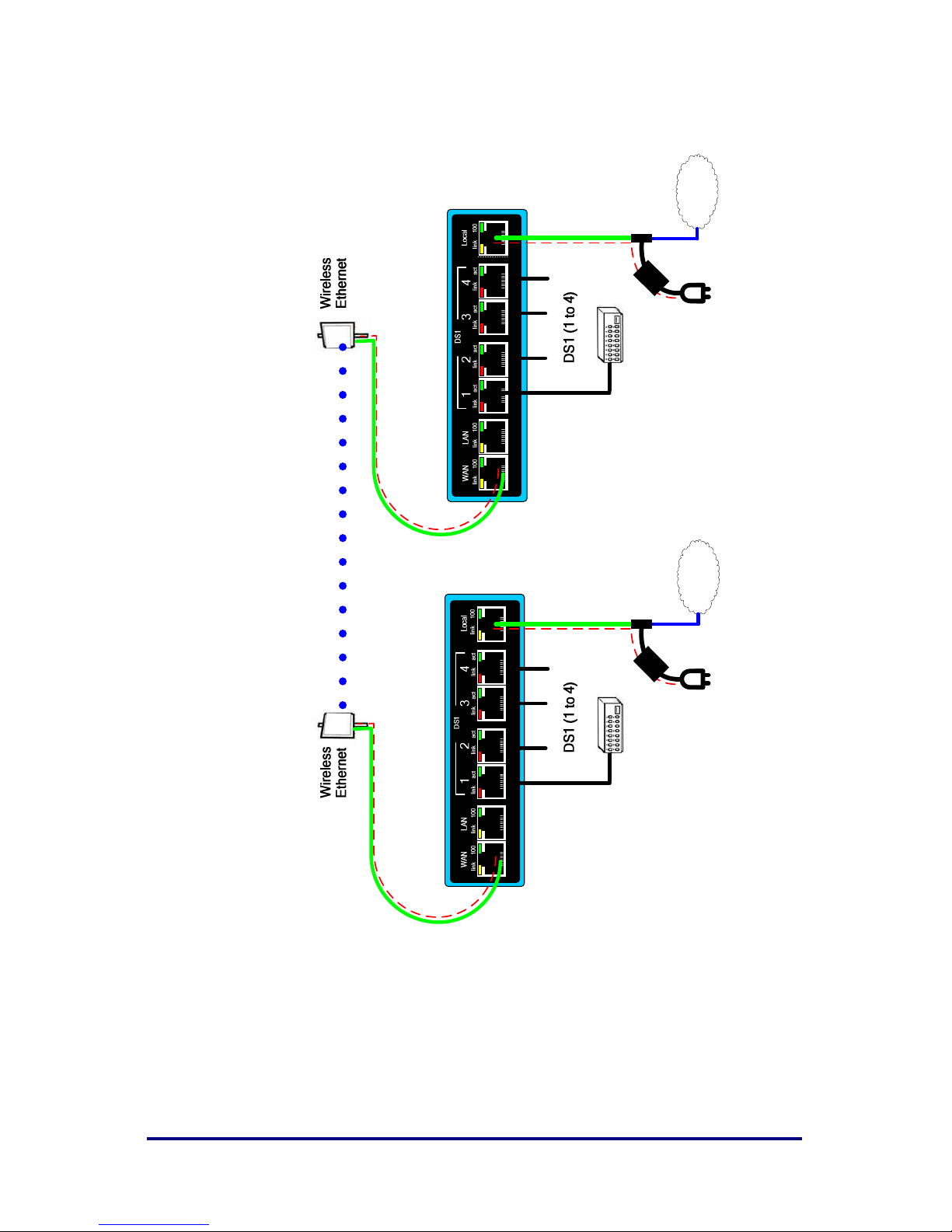
Example Interconnections
Power in
Flanger4Plus
Power Supply
LAN
Flanger4Plus
Power Supply
P
o
w
e
r
o
u
t
P
o
w
e
r
o
u
t
LAN

For Build 050109 and later
9
Setting Clock Modes
The Flanger4Plus supports five DS1 clock modes on a per-channel basis.
Mode 0 – Derive clock from this DS1 line
Mode 1 – Flanger4Plus generates clock internally
Mode 2 – Derive clock from local DS1 line #1
Mode 3 – Derive clock from remote DS1 line #1
Mode 4 – Derive clock from remote this DS1 line
Flanger4Plus is factory configured and with all ports set
to either Mode 2 or Mode 3. You may need to
reconfigure to match your system configuration.
When to use Mode 2 to Mode 3 Pairs
Use this configuration when connecting network equipment that provides its
own stable timing source to remote equipment that recovers timing from the
received DS1 signal.
This is the factory default configuration for a Flanger4Plus pair. It is
recommended that this configuration be used unless the equipment on
channels 2, 3, and/or 4 use a different clock source than that on channel 1.

10
For Build 050109 and later
When to use Mode 0 to Mode 4 Pairs
Use this configuration when connecting network equipment that provides its
own stable timing source and remote equipment that recovers timing from
the received DS1 signal for each DS1 line independently.
When to use Mode 1 to Mode 3 Pairs
Use this configuration when connecting network equipment that expects to
receive stable timing from the Flanger4Plus and remote equipment that
recovers timing from the received DS1 signal for DS1 line #1 directly.

For Build 050109 and later
11
Using Equalizer Control Settings
Equalization settings are used to match the DS1 analog front end to the
length and characteristics of the cabling connected between the
Flanger4Plus unit and other TDM equipment.
Short haul settings are used in an intra-office installation. For short haul T1
installations, the EQ settings are directly determined by the cabling distance
between the Flanger4Plus and other equipment. For short haul E1
installations, there is only one EQ setting choice.
Cable Diagrams
Flanger4Plus uses RJ-45 connectors for DS1 and Ethernet cables. The cable
diagrams in the following sections refer to pin numbers. These pin numbers
refer to the actual pins illustrated below.
12
For Build 050109 and later
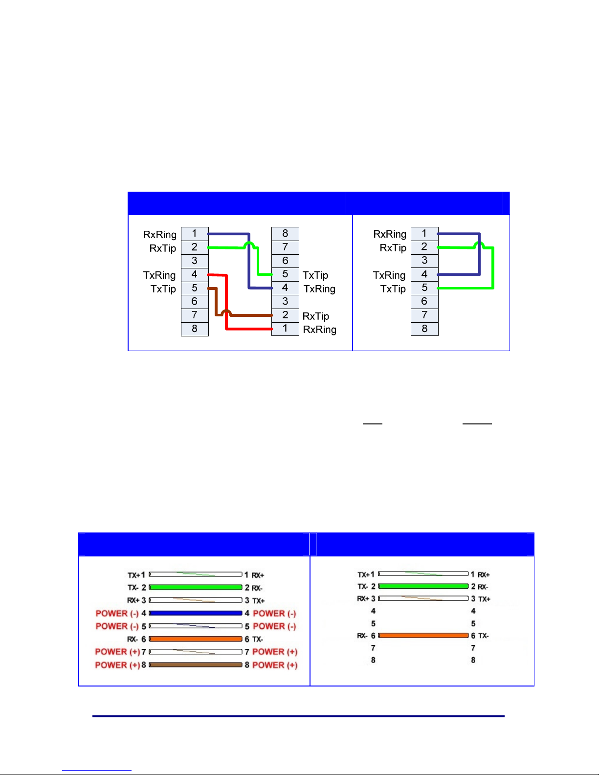
DS1 with RJ-45 Cable Diagrams
The DS1 ports normally require a cross-over cable between it and the CPE
(Customer Premise Equipment.) These cables can be made with a standard
CAT5 Ethernet cable using the pin out drawings below.
You can use a loop back plug in the Flanger4Plus remote unit to do bench
testing.
DS1 Crossover Cable DS1 Loop-Back Plug
CAT5 Ethernet Cable Diagrams
Used by cable from your provider power supply into Local port and out of
WAN port.
Note: Although the Flanger4Plus unit supports reversed polarity on its
power leads, other equipment powered by the Flanger4Plus may not.
Note: The Ethernet cable should be limited to a maximum of 100
meters or approx. 328 feet.
Pinout with Power over CAT5 Pinout without Power over CAT5

For Build 050109 and later
13
Accessing the User Interface
In order to access the Flanger4Plus Web interface, use your favorite Web
Browser program (e.g. Internet Explorer). The units can be accessed as
follows:
14
For Build 050109 and later
Login
For security purposes, Flanger4Plus requires a login whenever accessing the
Web Configuration pages or the command line interface (via telnet). If you
exceed the maximum number of login retry attempts, you need to cycle
power to Flanger4Plus before you can try to login again.
Once login is successful, a session is established. Keyboard activity is used
to determine session activity. When there is no activity exceeding the
session timeout, you must to login again.
The default factory configured username and password
is “admin”. The default number of login retry attempts is
unlimited and the session inactivity timeout is 600
seconds.
Factory Configuration Recovery
In order to restore a Flanger4Plus to a factory Clock Mode 2 configuration,
perform the following:
1. Connect the WAN Port of the Flanger 4 Plus to its Local Port using the
Flanger 4 Plus Power supply to provide power to the unit.
2. Apply power to the unit.
3. Observe the front panel LED. It will blink with an alternating Orange /
Green pattern once the unit has been restored. In the event that the front
panel LED stays solid green, disconnect the WAN port while power is
applied. The front panel LED will blink with an alternating Orange / Green
pattern once the unit has been restored.
The restored configuration of the Flanger 4 Plus is shown in the IP Defaults
table. All equipped channels will be disabled and set to T1.

For Build 050109 and later
15
Factory Default Configuration
Flanger4Plus is shipped in pairs and although they may sometimes have
sequential serial numbers, there is no requirement they do.
IP Defaults
Unit with Clock Mode 2 Unit with Clock Mode 3
Local WAN Local WAN
IP
192.168.1.1 169.254.1.50 192.168.2.1 169.254.1.60
Subnet
255.255.255.0 255.255.255.0 255.255.255.0 255.255.255.0
Gateway
0.0.0.0 169.254.1.50 0.0.0.0 169.254.1.60
Remote IP
169.254.1.60 169.254.1.50
Speed/Duplex
100 Mbps / Auto 100 Mbps / Auto
DS1 Defaults
Unit with Clock Mode 2 Unit with Clock Mode 3
Bit Clock
Source
Mode 2 – DS1 Line Mode 3 – Remote Global Sync
Encoding
Method
B8ZS/HDB3
Transmit
Template
As ordered: E1 Short Haul
Profile
ETHERNET-100
Max Rate = 100 Mbps
Safety Factor = 10%
Wayside Timeout = 5 seconds
Timing Pulse = No
Payload Size = 1024
Jitter Buffer = 8192
Jitter Window = 75
Min Gain = 0.200000
Max Step = 0.05
Stability Factor = 100
Loops = 240
Integrator = Yes
Final Sample Size = 1
SES Limit = 30
Track OOE = Yes
Use Remote Status = Yes

16
For Build 050109 and later
Features and Specifications
Communications Ports
Three 10/100base T; meets IEEE 802.3
Four T1/E1: RJ-45; meets ANSI T1.403, ITU-T G.703; AT&T TR-62411
Visual Status Indicators (LED)
Front STATUS (front panel for overall unit operating condition)
Back Local, LAN and WAN Ethernet Link Speed (10/100)
Local, LAN and WAN Connection / Link Activity
TDM (1,2,3,4) Signal Present
TDM (1,2,3,4) Activity
Console Power On and Clock Adjustment
Physical
5.5 in x 7 in x 2.3 in ; 14 cm x 18 cm x 5.9 cm
0.8 lb; 0.36 kg
Power Input
In-line “brick” power supply provides 24 to 56VDC to unit; requires 100 to
260 VAC, 47 to 63 Hz, 24 Watts
Environmental
Operating temperature: 0ºC (32ºF) to 50ºC (122ºF) ambient
Storage temperature: -30ºC (-22ºF) to +80ºC (176ºF)
Humidity, operating and storage: 95% non-condensing
Regulatory
FCC approval Title 47 Part 15, subpart B, Class A devices
CE
Restriction of Hazardous Substances – RoHS Directive 2002/95/EC
compliant
Contact your provider for the latest Flanger4Plus documentation
and utilities.
 Loading...