

Memorex MVD-4540 Service manual

CLASS 1
LASER PRODUCT
MVD4540
SERVICE MANUAL
DVD VIDEO PLAYER & VHS VIDEO CASSETTE RECORDER
ORIGINAL
MFR'S VERSION A
Design and specifications are subject to change without notice.
IMPORTANT WARNING
CAUTION:
DVD PLAYER IS A CLASS 1 LASER PRODUCT. HOWEVER THIS PLAYER USES A VISIBLE LASER
BEAM WHICH COULD CAUSE HAZARDOUS RADIATION EXPOSURE IF DIRECTED. BE SURE TO
OPERATE THE PLAYER CORRECTLY AS INSTRUCTED.
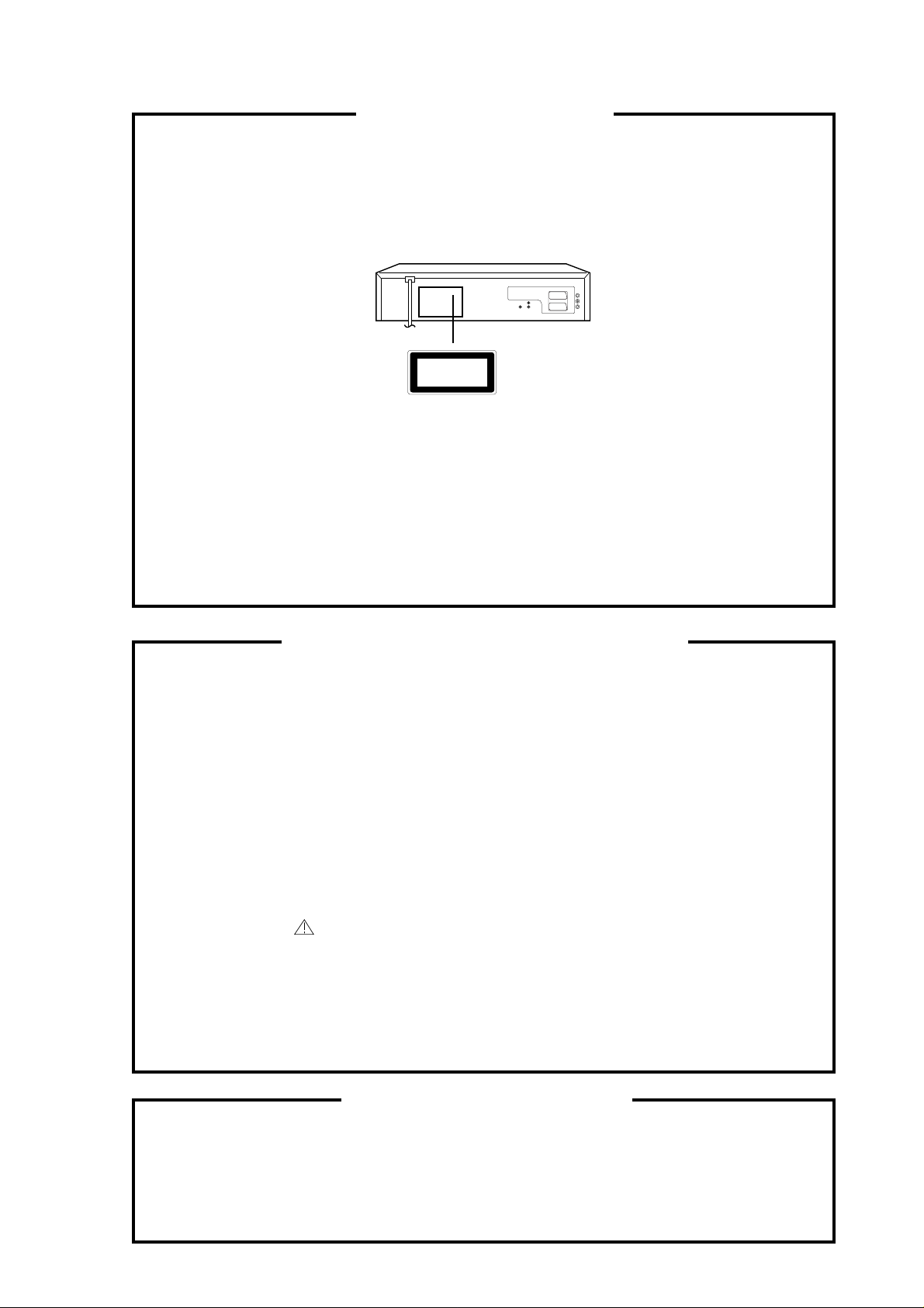
THE FOLLOWING CAUTION LABEL IS LOCATED ON THE REAR PANEL OF THE PLAYER.
CLASS 1
LASER PRODUCT
(Printed on the Rear Panel)
WHEN THIS PLAYER IS PLUGGED TO THE WALL OUTLET, DO NOT PLACE YOUR EYES CLOSE
TO THE OPENING OF THE DISC TRAY AND OTHER OPENINGS TO LOOK INTO THE INSIDE OF
THIS PLAYER.
USE OF CONTROLS OR ADJUSTMENTS OR PERFORMANCE OF PROCEDURES OTHER THAN
THOSE SPECIFIED HEREIN MAY RESULT IN HAZARDOUS RADIATION EXPOSURE.
DO NOT OPEN COVERS AND DO NOT REPAIR YOURSELF. REFER SERVICING TO QUALIFIED
PERSONNEL.
SERVICING NOTICES ON CHECKING
1. KEEP THE NOTICES 3. PUT PARTS AND WIRES IN THE
As for the places which need special attentions,
they are indicated with the labels or seals on the
cabinet, chassis and parts. Make sure to keep the
indications and notices in the operation manual.
2. USE THE DESIGNATED PARTS
The parts in this equipment have the specific
characters of incombustibility and withstand
voltage for safety. Therefore, the part which is
replaced should be used the part which has
the same character.
Especially as to the important parts for safety
which is indicated in the circuit diagram or the
table of parts as a mark, the designated
parts must be used.
ORIGINAL POSITION AFTER
ASSEMBLING OR WIRING
There are parts which use the insulation
material such as a tube or tape for safety, or
which are assembled in the condition that
these do not contact with the printed board.
The inside wiring is designed not to get closer
to the pyrogenic parts and high voltage parts.
Therefore, put these parts in the original
positions.
PERFORM A SAFETY CHECK AFTER
4.
SERVICING
Confirm that the screws, parts and wiring which
were removed in order to service are put in the
original positions, or whether there are the
portions which are deteriorated around the
serviced places serviced or not. Check the
insulation between the antenna terminal or
external metal and the AC cord plug blades.
And be sure the safety of that.
HOW TO ORDER PARTS
Please include the following informations when you order parts. (Particularly the VERSION LETTER.)
1. MODEL NUMBER and VERSION LETTER
The MODEL NUMBER can be found on the back of each product and the VERSION LETTER can be
found at the end of the SERIAL NUMBER.
2. PART NO. and DESCRIPTION
You can find it in your SERVICE MANUAL.
A1-1
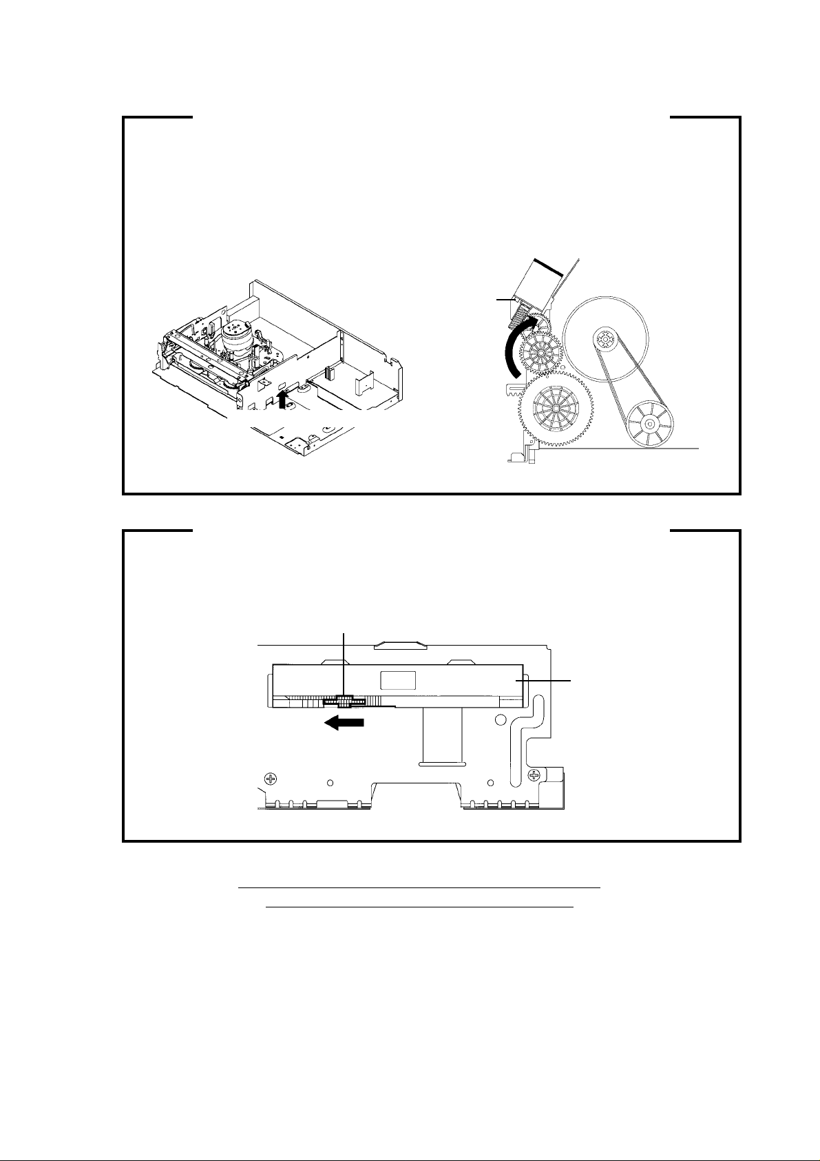
TAPE REMOVAL METHOD AT NO POWER SUPPLY
1.
Remove the Top Cabinet, Front Cabinet and DVD Block and the Fig. 1 below can be seen.
(Refer to item 1 of the DISASSEMBLY INSTRUCTIONS.)
2.
Remove one screw of the Loading Motor from the insert hole for screw driver and remove the Loading
Motor.
3.
Rotate the Pinch Roller Cam in the direction of the arrow by hand to slacken the Video Tape.
(Refer to Fig. 2)
4.
Rotate the Clutch Ass'y either of the directions to wind the Video Tape in the Cassette Case.
5.
Repeat the above step 3~4. Then take out the Video Cassette from the Deck Chassis. Be careful not to
scratch on the tape.
Loading Motor
Screw
Capstan DD Unit
Pinch Roller Cam
Insert hole for screw driver
Fig. 1
Main Cam
Clutch Ass'y
Main Chassis (Front Side)
Fig. 2
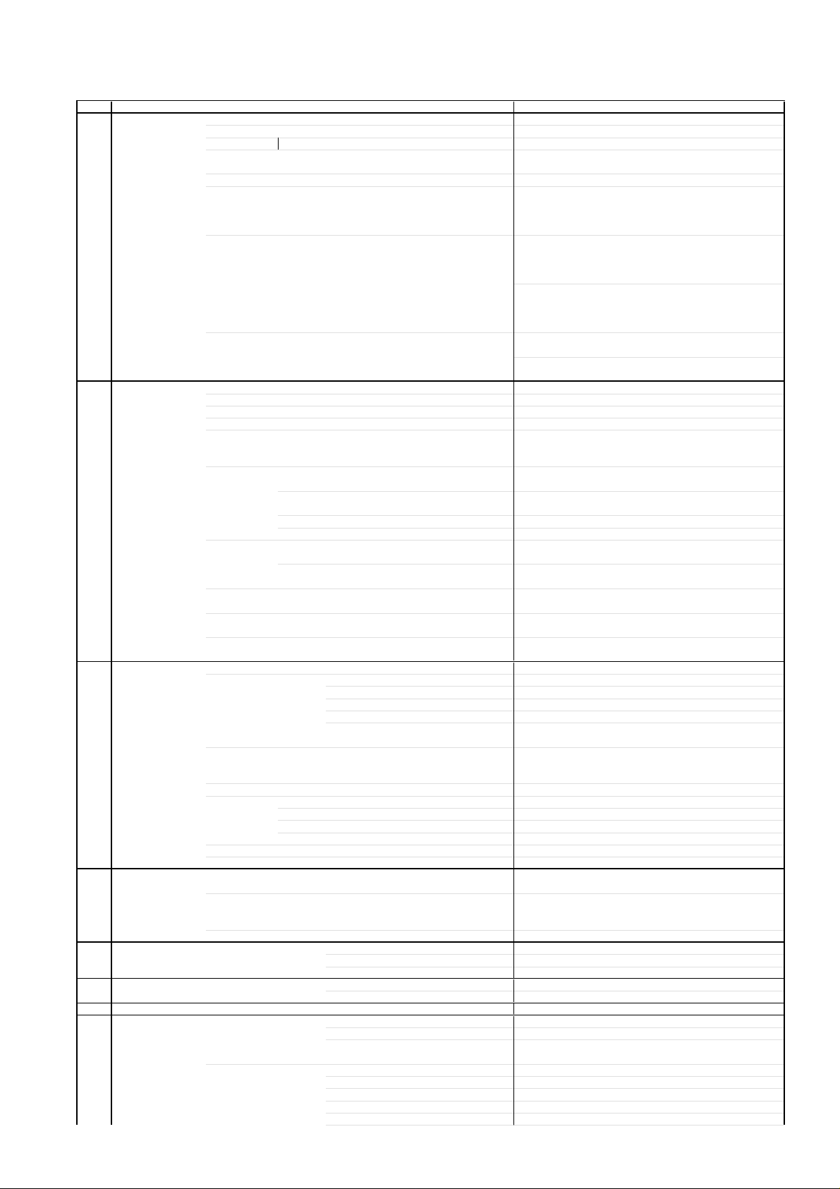
DISC REMOVAL METHOD AT NO POWER SUPPLY
1.2.Remove the Top Cabinet and Front Cabinet. (Refer to item 1 of the DISASSEMBLY INSTRUCTIONS.)
Rotate the gear of Deck CD section in the direction of the arrow by hand, remove the disc from Deck
CD. (Refer to Fig. 3)
Gear
Deck CD
Fig. 3
PARENTAL CONTROL - RATING LEVEL
4-DIGIT SECURITY CODE CANCELLATION
If the stored 4-digit security code in the Rating Level menu needs to be cancelled, please follow the steps below.
Connect the set to TV Monitor.
1.
Turn on the power, and set to the DVD stop mode.
2.
Press the SET UP button to display the DVD menu.
3.
Press the SET +/- button to select the "Operation" menu.
4.
Press the CH UP/DOWN button to select the Parental Lock, then press the ENTER button.
5.
Press the CH UP/DOWN button to select the ON or OFF, then press the ENTER button.
6.
Press the STOP button four times on the remote control, then press the ENTER button.
7.
The 4-digit security code is cleared.
Press the SET UP button to disappear the DVD menu.
8.
A1-2

TABLE OF CONTENTS
IMPORTANT WARNING ............................................................................................................
SERVICING NOTICES ON CHECKING....................................................................................
HOW TO ORDER PARTS ..........................................................................................................
TAPE REMOVAL METHOD AT NO POWER SUPPLY ............................................................
DISC REMOVAL METHOD AT NO POWER SUPPLY .............................................................
PARENTAL CONTROL-RATING LEVEL ..................................................................................
TABLE OF CONTENTS..............................................................................................................
GENERAL SPECIFICATIONS ...................................................................................................
DISASSEMBLY INSTRUCTIONS
1. REMOVAL OF MECHANICAL PARTS AND P. C. BOARDS............................................
2. REMOVAL OF VCR DECK PARTS ...................................................................................
3. REMOVAL AND INSTALLATION OF FLAT PACKAGE IC ...............................................
KEY TO ABBREVIATIONS ........................................................................................................
SERVICE MODE LIST ................................................................................................................
PREVENTIVE CHECKS AND SERVICE INTERVALS..............................................................
WHEN REPLACING EEPROM (MEMORY) IC ..........................................................................
SERVICING FIXTURES AND TOOLS .......................................................................................
PREPARATION FOR SERVICING.............................................................................................
MECHANICAL ADJUSTMENTS ................................................................................................
ELECTRICAL ADJUSTMENTS..................................................................................................
BLOCK DIAGRAMS
DVD..........................................................................................................................................
Y/C/AUDIO/CCD/HEAD AMP .................................................................................................
SYSTEM CONTROL ..............................................................................................................
REGULATOR..........................................................................................................................
DISPLAY/OPERATION ..........................................................................................................
HI-FI/DEMODULATOR...........................................................................................................
TUNER/JACK .........................................................................................................................
DVD/HDD IN/OUT ..................................................................................................................
POWER ..................................................................................................................................
PRINTED CIRCUIT BOARDS
DVD MT ...................................................................................................................................
VCR MT ..................................................................................................................................
POWER/OPERATION ............................................................................................................
SCHEMATIC DIAGRAMS
READ CHANNEL....................................................................................................................
DSP.........................................................................................................................................
MPEG......................................................................................................................................
MEMORY ................................................................................................................................
AUDIO/VIDEO ........................................................................................................................
SYSCON1...............................................................................................................................
Y/C/AUDIO/CCD/HEAD AMP .................................................................................................
VCR SYSCON .........................................................................................................................
TUNER/JACK ..........................................................................................................................
REGULATOR...........................................................................................................................
DISPLAY..................................................................................................................................
HI-FI/DEMODULATOR............................................................................................................
DVD/HDD IN/OUT ...................................................................................................................
POWER ...................................................................................................................................
OPERATION............................................................................................................................
INTERCONNECTION DIAGRAM ...............................................................................................
WAVEFORMS .............................................................................................................................
MECHANICAL EXPLODED VIEW .............................................................................................
CHASSIS EXPLODED VIEWS ...................................................................................................
MECHANICAL REPLACEMENT PARTS LIST .........................................................................
CHASSIS REPLACEMENT PARTS LIST..................................................................................
ELECTRICAL REPLACEMENT PARTS LIST...........................................................................
A1-1
A1-1
A1-1
A1-2
A1-2
A1-2
A2-1
A3-1~A3-5
B1-1, B1-2
B2-1~B2-6
B3-1, B3-2
C1-1, C1-2
C2-1
C3-1, C3-2
C4-1
D1-1
D1-1
D2-1~D2-4
D3-1, D3-2
E-1, E-2
E-3, E-4
E-5, E-6
E-7, E-8
E-9, E-10
E-11, E-12
E-13, E-14
E-15, E-16
E-17, E-18
F-1, F-2
F-3~F-6
F-7, F-8
G-1, G-2
G-3, G-4
G-5, G-6
G-7, G-8
G-9, G-10
G-11, G-12
G-13, G-14
G-15, G-16
G-17, G-18
G-19, G-20
G-21, G-22
G-23, G-24
G-25, G-26
G-27, G-28
G-29, G-30
G-31, G-32
H-1~H-3
I1-1
I2-1, I2-2
J1-1
J2-1
J3-1~J3-3
A2-1
GENERAL SPECIFICATIONS
G-1 Outline of the product DVD VIDEO PLAYER & VHS Player / Recorder
G-2 DVD System Color System NTSC
G-3 VCR System VHS Player / Recorder
System Video System NTSC
Disc DVD, CD-DA, CD-R/RW
Disc Diameter 120 mm , 80 mm
Deck Disc Loading System Front Disc Loding
Motor 3 Motors
Pick up 1-Lens 2-Beams System
Playback time (Max) DVD 1-Layer 135min (4.7GB)
245min (8.5GB)
CD 74min
VIDEO CD --min
Search speed Fwd 2-100 times / 4 step (DVD)
4-8 times / 2 step (CD)
Actual 2-70 times (DVD)
4-12times (CD)
Rev 2-100 times / 4 step (DVD)
4-8 times / 2 step (CD)
Actual 2-70 times (DVD)
4-16times (CD)
Slow speed Fwd 1/8-1/2 times
Actual 1/7-1/2 times (DVD)
Rev --
Actual --
Hi-Fi STEREO Yes
NTSC PB(PAL60Hz) No
Deck DECK OVD-7
Loading System Front
Motor 3
Heads Video Head 4Head
FM Audio Head 2Head
Audio /Control Mono/Yes
Erase(Full Track Erase) Yes
Tape Rec PAL Speed NTSC SP/SLP
Play PAL -
NTSC SP/LP/SLP
Fast Forward / Rewind Time (Approx.) at 25oC FF:1'48"/REW:1'48"
with Cassette T-120
Forward/Reverse NTSC or PAL-M SP/LP/SLP = 3x,5x / 7x,9x / 9x,15x
Picture Search PAL or SECAM Frame Advance 1/10
Slow Speed 1/10
G-4 Tuning Broadcasting System US System M
System Tuner and System 1Tuner
Receive CH Destination US(w/CATV)
Tuning System F-Synth
Input Impedance VHF/UHF 75 OHM
CH Coverage
2-69,4A,A-5~ A-1,A~I,
J~ W, W+1-W+84
Intermediate Picture(FP) 45.75 MHz
Frequency Sound(FS) 41.25 MHz
FP-FS 4.50 MHz
Preset CH RF Converter Output Yes
Channel 3 or 4 ch
Level/Impedance 66 dBu / 75 Ohm
Sound Selector No
Stereo/Dual TV Sound US-ST
Tuner Sound Muting Yes
G-5 Power Power Source AC 120V 60Hz
DC -
Power Consumption 20 W at 120V 60Hz
Stand by 3 W at 120V 60Hz
Per Year -- W
Protector Power Fuse Yes
G-6 Regulation Safety UL
Radiation FCC
Laser DHHS
o
G-7 Temperature Operation
G-8 Operating Humidity Less then 80% RH
Storage
-
o
-
o
o
-
G-9 Signal Video Signal Output Level 1 V p-p/75 ohm (DVD,VCR)
S/N Ratio (Weighted) 65 dB(DVD) 50 dB(VCR)
Horizontal Resolution 500 Lines (DVD) 230 Lines(VCR Mode)
RGB Signal Output Level Audio Signal Input Level Microphone -
Input Level Line -8 dBm/ 50k ohm(VCR)
(0dB=0.775Vrms) Output Level Line -8 dBm/ 1k ohm(DVD,VCR)
Digital Output Level 0.5 V p-p / 75 ohm(DVD)
S/N Ratio at (Weighted) 90dB(DVD), 42dB(VCR at SP)
A3-1

GENERAL SPECIFICATIONS
y
Harmonic Distortion (1KHz)
T
Frequency Response : DVD Mode at DVD 4 Hz - 22 KHz
Hi-Fi Audio Signal Dynamic Range : More than 90dB
G-10 On Screen
Display Menu Type Icon
On Screen Menu Yes
Display(VCR) Menu Type Character
(DVD)
Menu Yes
Picture Yes
Output Sound Yes
Language Yes
Display Yes
Operational Yes
Initial Setup Yes
Open Yes
Close Yes
No disc Yes
Reading Yes
Play Yes
Still/Pause Yes
Stop Yes
Prohibit Mark Yes
Step Yes
Skip+ Yes
Skip- Yes
Random Yes
Repeat Yes
A-B Repeat Yes
Slow+ Yes
Slow- No
Search+ Yes
Search- Yes
Resume Yes
Title No. Yes
Chapter No. Yes
Track No. Yes
Time Yes
Sub Title No. Yes
Angle No. Yes
Audio No. Yes
Zoom Yes
Enter Yes
Exit Yes
Bit Rate Yes
Memory Yes
Timer Rec Set Yes
Auto Repeat On/Off Yes
SAP On/Off Yes
Surround On/Off No
CH Set-Up Yes
System Set Up Yes
Frequency Response 20Hz ~20kHz
Wow And Flutter : Less than 0.01 %Wrms
Channel Separation : More than 60 dB
Harmonic Distortion : Less than 0.01
TV Shape Yes
Audio Out Select Yes
Dynamic Range Control Yes
Karaoke Vocal Yes
On-Screen Language Yes
Disc Menu Language Yes
Audio Language Yes
Subtitle Language Yes
On-Screen Displays Yes
Background Yes
Screen Saver Yes
Pause/Still Yes
Parental Lock Yes
Title Stop Yes
PBC No
On-Screen Language Yes
TV Shape Yes
Audio Out Select Yes
TV/CATV Yes
Auto CH Memory Yes
Add/Delete Yes
Guide CH No
Clock Set Yes (Calendar 12H)
Language Yes
pical
DVD Mode at VIDEO CD -
DVD Mode at CD 4 Hz - 20 KHz
VCR Mode at SP 100Hz - 10 KHz
VCR Mode at LP -
VCR Mode at SLP 100Hz - 4 KHz
A3-2
0.008% (1KHz) (DVD) , 1.5% (1KHz) (VCR)

GENERAL SPECIFICATIONS
(Sy
)
,FF(
No Noise Back Ground Yes
Auto Clock Yes
Standard Time Yes
G-CODE(or SHOWVIEW or PLUSCODE)No. Entry No
Stereo,Audio Output,SAP Yes
Play/Stop/FF/Rew/Rec/OTR/T-Rec/Pause/Eject/Tape In/Repeat
G-11 OSD Language DVD OSD Eng Fre Spa
VCR OSD Eng Fre Spa
G-12 Clock,Timer Calendar 1990/1/1 ~ 2081/12/31
and Timer Timer Events 8 Program/ 1 Month
Back-up One Touch Recording Max Time 5 Hours(30,60,90,120,180,240,300)
OTPB Valid Time No
Timer Back-up (at Power Off Mode) 5sec
G-13 Display DISPLAY Yes
G-14 Remote Unit RC-ET
Control Glow in Dark Remocon No
Power Source Voltage(D.C) 3V
Total Keys 45 Key
Keys Power Yes
Daylight Saving Time Yes
mbol Mark
CH/AV Yes
Clock Yes
Repeat Yes
Pin Code No
Tape Counter Yes
Index Yes
Hotel Lock No
Tape Speed Yes
ATR / Manual Tracking Yes
Hi-Fi Yes
DISPLAY type LED Module (Green, "Rec" &Timer symbol = Red)
Clock/Counter,CH,Timer Rec,OTR, Play
Rec
VCR Yes
DVD Yes
CD Yes
Clock
Counter VCR Yes (hour:min)
Counter Remain No
Play Yes
Stop No
Rec Yes
FF / Cue No
REW /Review No
Pause/Still Yes
OTR No
T-Rec Yes
Chapter No
TITLE No
TRACK Yes
Repeat No
Hi-Fi No
SP No
LP No
SLP No
CH Yes
RF Output CH No
Eject Yes
Tape In Yes
UM size x pcs UM-4 x 2 pcs
DISPLAY/CALL Yes
1 Yes
2 Yes
3 Yes
4 Yes
5 Yes
6 Yes
7 Yes
8 Yes
9 Yes
0 Yes
Input Select Yes
UP/CH+- Yes
DOWN/CH- Yes
LEFT/ SET- / TRACKING- Yes
RIGHT/ SET+ / TRACKING+ Yes
VCR/DVD Yes
TV/VCR Yes
DVD MENU Yes
Cue),Rew(Rev),Stop,ATR,Eject
DVD Yes (hour:min)
Yes
Yes (12h)
AM
Yes
PM
CD Yes (min:sec)
No
No
A3-3

GENERAL SPECIFICATIONS
TITLE Yes
SET UP MENU/VCR MENU Yes
SELECT/ENTER Yes
CLEAR/CANCEL Yes
RETURN Yes
PLAY Yes
STOP Yes
PAUSE/STILL Yes
FF(Cue)/SEARCH+ Yes
REW(Review)/SEARCH- Yes
REC/OTR Yes
SKIP+ / INDEX+ Yes
SKIP- / INDEX- Yes
AUDIO / AUDIO SELECT Yes
ANGLE/COUNTER RESET Yes
SUB TITLE/ATR Yes
PLAY MODE/SPEED Yes
T-REC Yes
CLOCK / COUNTER Yes
MEMORY/ZERO RETURN Yes
ZOOM Yes
REPEAT A-B Yes
SLOW(Forward) Yes
MARKER No
OPEN/CLOSE Yes
G-15 Features Auto Power Off No
(DVD) Parental Lock Yes
Features Auto Head Cleaning Yes
(VCR) Auto Tracking Yes
G-16 Accessories Owner's Manual Language English /Spanish
G-17 Interface Switch Front Power Yes
Video CD Playback No
MP3 Playback Yes
Digital Out Dolby Digital Yes
Down Mix Out (Dolby Digital, MPEG1,MPEG2) Yes
Self Diagnostic No
Spatializer (N-2-2)
Screen Saver
HQ (VHS Standard High Quality) Yes
Auto Power On, Auto Play, Auto Rewind, Auto Eject Yes
Auto Power Off No
Forward/Reverse Picture Search Yes
VIDEO PLUS+(SHOWVIEW,G-CODE) No
One Touch Playback No
Auto CH Memory Yes
AREA CODE No
Auto Clock Set Yes
Index Search Yes
SQPB No
CATV Yes
Energy Star No
MTS(SAP) Yes
CM Skip(30sec x 6 Times) No
Power On Memory No
Surround No
Remote Control Unit Yes
Guarantee Card Yes
Registration Card No
Warning Sheet No
Service Station List No
Important Tag No
AC Plug Adapter No
Quick Set-up Sheet No
Battery No
AC Cord No
AV Cord Yes (1.2m)
75 Ohm Coaxial Cable Yes (0.9m)
S-Video Cable No
21pin cable No
800 No Sticker No
Toll Free Insert Sheet No
Safety Tip No
EJECT Yes
PCM Yes
DTS Yes
MPEG1,MPEG2 Yes
No
Yes
w/Guarantee Card No
UM size x pcs --
Play Yes
Eject (VCR) Yes
Stop Yes
Rec/OTR Yes
Open/Close (DVD) Yes
CH + Yes
A3-4
GENERAL SPECIFICATIONS
CH - Yes
FF/ Search(>>) Yes
Rew/Search(<<) Yes
Still/Pause No
Shuttle(Search/REV/FWD) No
DVD/VCR Yes
Rear Attenuator No
Volume Phones Volume No
Terminals Front Video In RCA x1(Yellow)
Rear Video Output RCA x1(Yellow)
Indicator LED Power No
G-18 Set Size Approx. W x D x H (mm) 430 x 314.5 x 99
G-19 Weight Net (Approx.) 4.5 kg( 9.9lbs)
G-20 Carton Master Carton No
Gift Box Yes
Drop Test
Container Stuffing 1,595 Sets/40' container
G-21 Cabinet Material Cabinet Front PS 94V2 or More / DECABROM
Main Power SW No
Video/RGB Selector No
RF Out(Slide SW) Yes (3ch/4ch)
Main Power SW No
Mic Volume No
Echo Volume No
Rec/OTR No
Audio In RCA x 2(Stereo, White/Red)
S-Video x 1(DVD Signal Only)
Component x1 (RCA 3pin,DVD Signal Only)
Audio Output RCA x 4(Stereo, White/Red)
Coaxial x 1 (Digital Audio,DVD Signal Only)
Optical Out (Option) Yes (Digital Audio,DVD Signal Only)
Video Input (Option) No
Audio Input (Option) No
RF Input / Output Yes
Euro Scart No
AC Inlet No
Rec No
T-Rec No
TV/VCR No
DVD Yes (RED)
VCR Yes (RED)
Surround No
Level Meter No
Gross (Approx.) 5.5 kg( 12.1lbs)
Content --- Sets
Material --- / --Dimensions W x D x H(mm) --Description of Origin ---
Material Dbule / White
W/Color Phote Label No
Dimensions W x D x H(mm) 500 x 430 x 180
Design As Per BUYER 's
Description of Origin Yes
Natural Dropping At 1 Corner / 3 Edges / 6 Surfaces
Height (cm) 80 cm
A3-5
DISASSEMBLY INSTRUCTIONS
1.
REMOVAL OF MECHANICAL PARTS
AND P.C. BOARDS
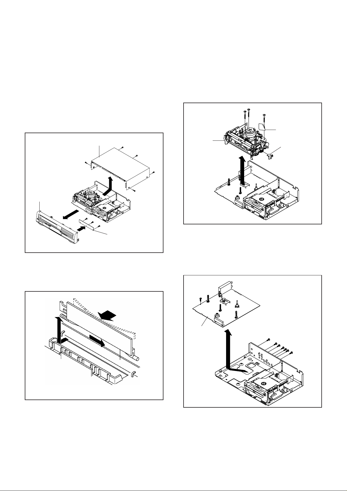
1-1:
TOP CABINET AND FRONT CABINET
(Refer to Fig. 1-1)
1.
Remove the 5 screws (1).
2.
Remove the Top Cabinet in the direction of arrow (A).
3.
Disconnect the following connector: (CP651).
4.
Unlock the 8 supports (2).
5.
Remove the Front Cabinet in the direction of arrow (B).
6.
Remove the 3 screws (3).
7.
Remove the Operation PCB in the direction of arrow (C).
Top Cabinet
(1)
(A)
Front Cabinet
(B)
(2)
(2)
(2)
(2)
(2)
(2)
(2)
(2)
(3)
(C)
(3)
(3)
1-2: FLAP (Refer to Fig. 1-2)
1.2.Open Flap to 90° and flex in direction of arrow (A), at
the same time slide in direction of arrow (B).
Then lift in direction of arrow (C).
(1)
(1)
(1)
Operation PCB
Fig. 1-1
(1)
1-3: VCR DECK (Refer to Fig. 1-3)
1.
Unlock the 2 supports (1) and remove the Top Holder.
2.
Remove the 3 screws (2).
3.
Disconnect the following connectors: (CP101, CP102,
CP103 and CP3001).
4.
Remove the AC Head Cover and VCR Deck in the
direction of arrow.
(2)
(2)
VCR Deck
(2)
AC Head Cover
Top Holder
(1)
(1)
1-4: VCR PCB (Refer to Fig. 1-4)
1.
Remove the screw (1).
2.
Remove the 7 screws (2).
3.
Disconnect the following connectors: (CP1701,
CP8001 and CP8002).
4.
Remove the VCR PCB in the direction of arrow.
(2)
Fig. 1-3
(C)
Bottom side
(B)
(A)
Flap
Upper side
Fig. 1-2
B1-1
VCR PCB
(1)
(2)
(2)
(2)
(2)
(2)
(2)
Fig. 1-4
DISASSEMBLY INSTRUCTIONS
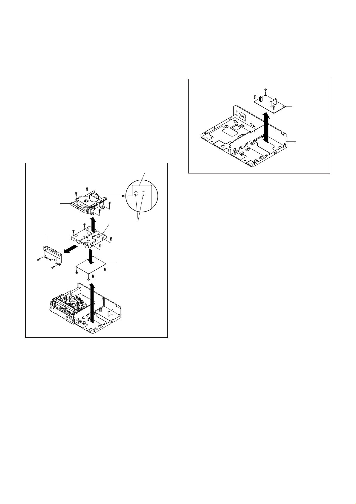
1-5: DECK CD AND DVD PCB (Refer to Fig. 1-5) 1-6: POWER PCB (Refer to Fig. 1-6)
1.
Make the short circuit on the position as shown Fig. 1-5
using a soldering. If you remove the Deck CD with no
soldering, the Laser may be damaged.
2.
Disconnect the following connector: (CP503).
3.
Remove the 4 screws (1).
4.
Remove the Deck Angle in the direction of arrow (A).
5.
Remove the 2 screws (2).
6.
Remove the Front-DVD Shield in the direction of arrow
(B).
7.
Remove the 4 screws (3).
8.
Disconnect the following connectors: (CP2601,
CP2602 and CP2603).
9.
Remove the Deck CD in the direction of arrow (C).
10.
Remove the 4 screws (4).
11.
Remove the DVD PCB in the direction of arrow (D).
1.2.Remove the 3 screws (1).
Remove the Power PCB in the direction of arrow.
(1)
(1)
(1)
Power PCB
Bottom Plate
Deck CD
Front-DVD Shield
(2)
(2)
(B)
(4)
(1)
(3)
(4)
(1)
(D)
(3)
(3)
(C)
(1)
(4)
(A)
(3)
Deck Angle
(1)
(4)
Pick Up PCB
Make the sort circuit
using a soldering.
DVD PCB
Fig. 1-6
Fig. 1-5
NOTE
When the installation of the Deck CD, remove all the
soldering on the short circuit position after the connection of
Pick Up PCB and DVD PCB connector.
B1-2
DISASSEMBLY INSTRUCTIONS
2. REMOVAL OF VCR DECK PARTS
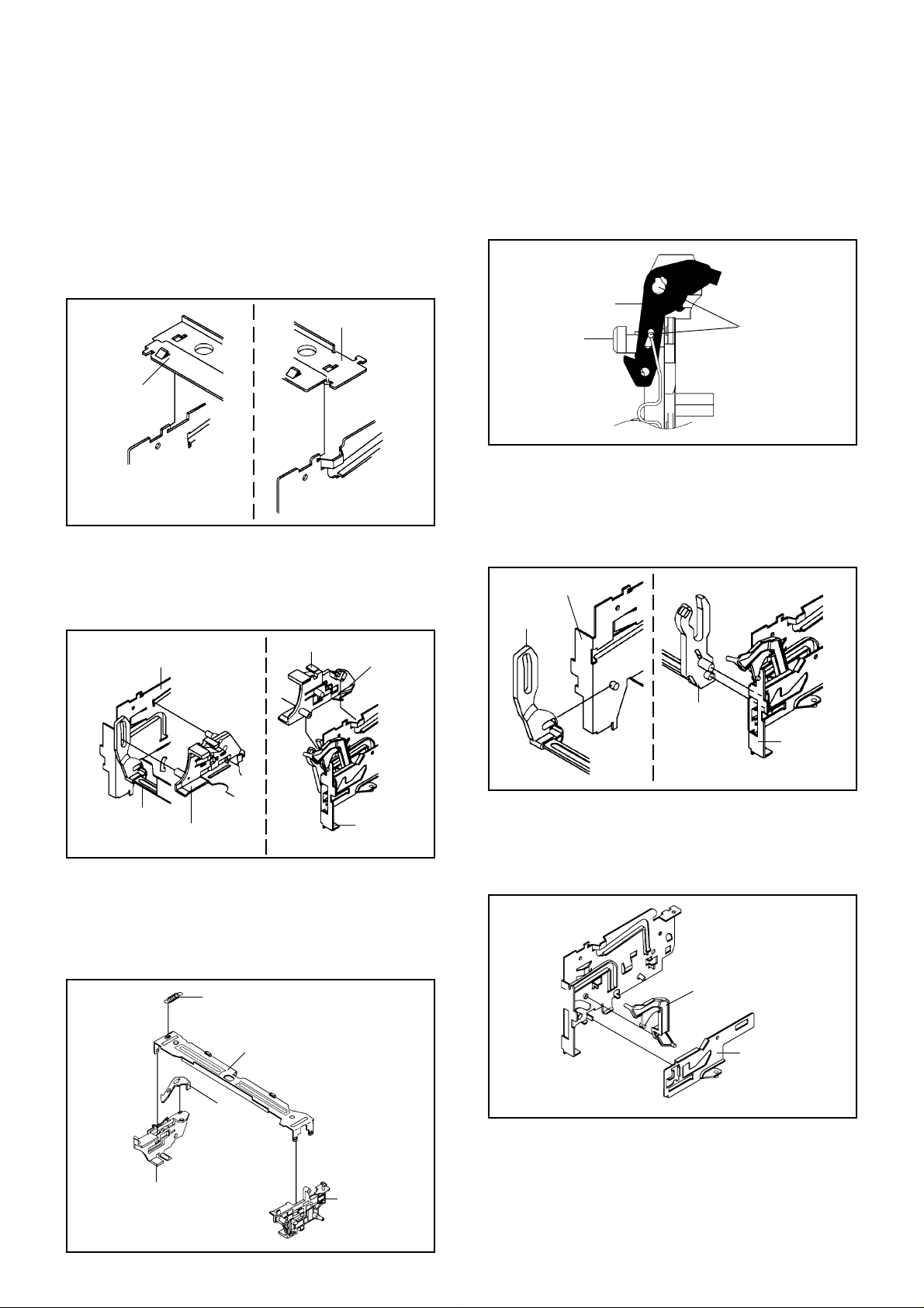
2-1: TOP BRACKET (Refer to Fig. 2-1)
Extend the 2 supports (1).
1.
Slide the 2 supports (2) and remove the Top Bracket.
2.
NOTE
1. After the installation of the Top Bracket, bend the
support (1) so that the Top Bracket is fixed.
Top Bracket
(1)
Top Bracket
(2)
Main Chassis
(2)
Main Chassis
2-2: CASSETTE HOLDER ASS'Y (Refer to Fig. 2-2)
Move the Cassette Holder Ass'y to the front side.
1.
Push the Locker R to remove the Cassette Side R.
2.
Remove the Cassette Side L.
3.
Main Chassis
Cassette Side R
(1)
Fig. 2-1
Locker R
NOTE
1.2.In case of the Locker R installation, check if the two
positions of Fig.2-3-B are correctly locked.
When you install the Cassette Side R, be sure to move
the Locker R after installing.
Locker R
Check if these
Cassette Side R
positions are locked.
Fig. 2-3-B
2-4: LINK UNIT (Refer to Fig. 2-4)
Set the Link Unit to the Eject position.
1.
Unlock the support (1).
2.
Remove the (A) side of the Link Unit first, then remove
3.
the (B) side.
Main Chassis
Link Unit
Link Unit
Cassette Side L
Main Chassis
2-3: CASSETTE SIDE L/R (Refer to Fig. 2-3-A)
Remove the Locker Spring.
1.
Unlock the 4 supports (1) and then remove the
2.
Cassette Side L/R.
Unlock the support (2) and then remove the Locker R.
3.
Locker Spring
(1)
(1)
(2)
Cassette Holder
Locker R
(1)
(1)
Fig. 2-2
(A)
(1)
(B)
Link Unit
Main Chassis
2-5: LINK LEVER/FLAP LEVER (Refer to Fig. 2-5)
Extend the support (1).
1.
Remove the Link Lever.
2.
Remove the Flap Lever.
3.
Flap Lever
(1)
Link Lever
Fig. 2-4
Fig. 2-5
Cassette Side R
Cassette Side L
Fig. 2-3-A
B2-1
DISASSEMBLY INSTRUCTIONS
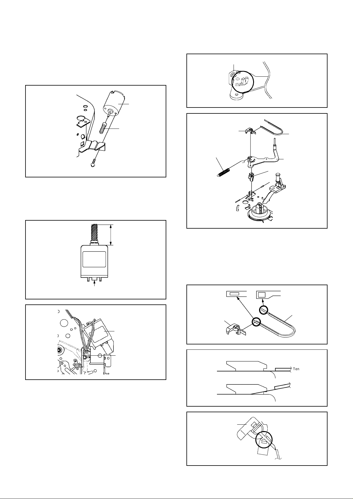
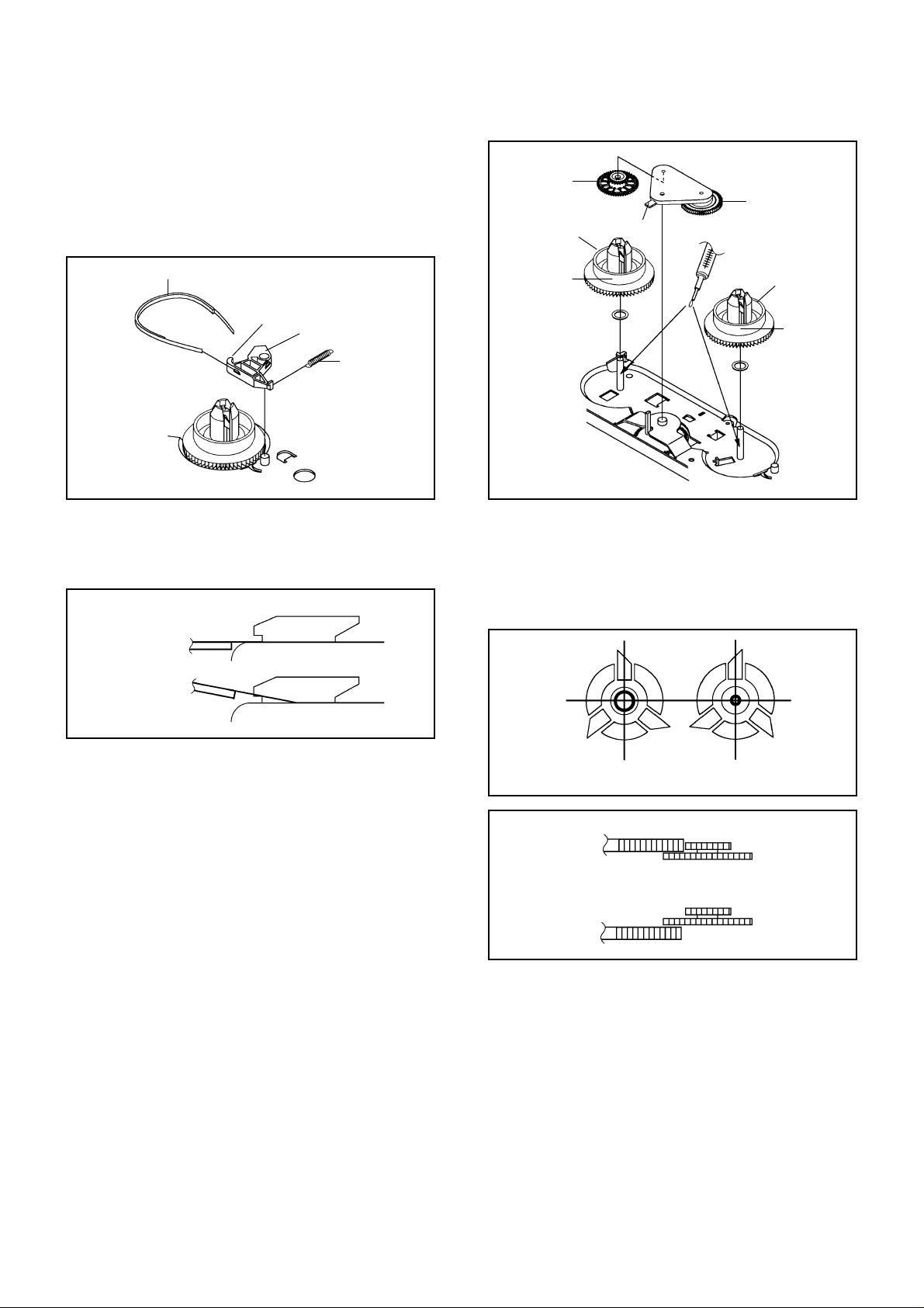
2-6: LOADING MOTOR/WORM (Refer to Fig. 2-6-A)
Remove the screw (1).
1.
Remove the Loading Motor.
2.
Remove the Worm.
3.
Loading Motor
Worm
Main Chassis
• Screw Torque: 3 ± 0.5kgf•cm
(1)
Fig. 2-6-A
NOTE
1.2.In case of the Worm installation, check if the value of
the Fig. 2-6-B is correct.
In case of the Loading Motor installation, hook the wire
on the Cassette Opener as shown Fig. 2-6-C.
Tension Arm Ass'y
Tension Connect
Tension Spring
(2)
(4)
(1)
(3)
Tension Holder
Fig. 2-7-A
(1)
Tension Band
Tension Arm Ass'y
Fig. 2-7-B
19.2 ± 0.1mm
Safety surface for pressing
of the insert.
Loading Motor
Cassette Opener
Fig. 2-6-B
Fig. 2-6-C
2-7: TENSION ASS'Y (Refer to Fig. 2-7-B)
Turn the Pinch Roller Cam clockwise so that the
1.
Tension Holder hook is set to the position of Fig. 2-7-A
to move the Tension Arm Ass'y.
Remove the Tension Spring.
2.
Unlock the 2 supports (1) and remove the Tension
3.
Band.
Unlock the support (2) and remove the Tension Arm
4.
Ass'y.
Unlock the support (3) and remove the Tension
5.
Connect.
Float the hook (4) and turn it clockwise then remove
6.
the Tension Holder.
B2-2
NOTE
1.
In case of the Tension Band installation, note the
direction of the installation. (Refer to Fig. 2-7-C)
2.
In case of the Tension Band installation, install correctly
as Fig. 2-7-D.
3.
In case of the Tension Connect installation, install as
the circled section of Fig. 2-7-E.
Tension Connect
Tension Band
Fig. 2-7-C
[OK]
[NG]
Tension Connect
Tension Connect
Tension Band
Tension Band
Fig. 2-7-D
Tension Connect
Main Chassis
Fig. 2-7-E
DISASSEMBLY INSTRUCTIONS
2-8: T BRAKE ARM/T BRAKE BAND (Refer to Fig. 2-8-A)
Remove the T Brake Spring.
1.
Turn the T Brake Arm clockwise and bend the hook
2.
section to remove it.
Unlock the 2 supports (1) and remove the T Brake
3.
Band.
Idler Gear
S Reel
Idler Arm Ass'y
(B)
T Brake Band
Hook section
(1)
(1)
T Brake Arm
T Brake Spring
Fig. 2-8-A
NOTE
1. In case of the T Brake Band installation, install correctly
as Fig. 2-8-B.
[OK]
T Brake Band
[NG]
T Brake Band
T Brake Arm
T Brake Arm
(A) T Reel
(1)
(A)
(1)
Fig. 2-9-A
NOTE
1.2.In case of the S Reel and T Reel installation, check if the
correct parts are installed. (Refer to Fig. 2-9-B)
In case of the Idler Arm Ass'y installation, install correctly
as Fig. 2-9-C. And also set it so that the section "B" of
Fig. 2-9-A is placed under the Main Chassis tab.
Fig. 2-8-B
2-9: S REEL/T REEL/IDLER ARM ASS'Y/IDLER GEAR
(Refer to Fig. 2-9-A)
Remove the S Reel and T Reel.
1.
Remove the 2 Polyslider Washers (1).
2.
Remove the Idler Arm Ass'y and Idler Gear.
3.
NOTE
Take care not to damage the gears of the S Reel and T
1.
Reel.
The Polyslider Washer may be remained on the back of
2.
the reel.
Take care not to damage the shaft.
3.
Do not touch the section "A" of S Reel and T Reel. (Use
4.
gloves.) (Refer to Fig. 2-9-A) Do not adhere the stains
on it.
When you install the reel, clean the shaft and grease it
5.
(FG-84M). (If you do not grease, noise may be heard in
FF/REW mode.)
After installing the reel, adjust the height of the reel.
6.
(Refer to MECHANICAL ADJUSTMENT)
[OK]
[NG]
Clutch Gear
Clutch Gear
Big Hole
(S Reel)
Small Hole
(T Reel)
Fig. 2-9-B
Idler Arm Ass'y
Idler Arm Ass'y
Fig. 2-9-C
B2-3
DISASSEMBLY INSTRUCTIONS
2-10:CASSETTE OPENER/PINCH ROLLER BLOCK/
P5 ARM ASS'Y (Refer to Fig. 2-10-A)
Unlock the support (1) and remove the Cassette
1.
Opener.
Remove the Pinch Roller Block and P5 Arm Ass'y.
2.
(1)
Cassette Opener
Pinch Roller Block
P5 Arm Ass'y
Main Chassis
Fig. 2-10-A
NOTE
Do not touch the Pinch Roller. (Use gloves.)
1.
In case of the Pinch Roller Block and the Pinch Roller
2.
Cam installation, install correctly as Fig. 2-10-B.
Pinch Roller Block
P5 Arm Ass'y
Can be seen the hole of the
Main Cam.
Can be seen the hole of
the Pinch Roller Cam.
Fig. 2-10-B
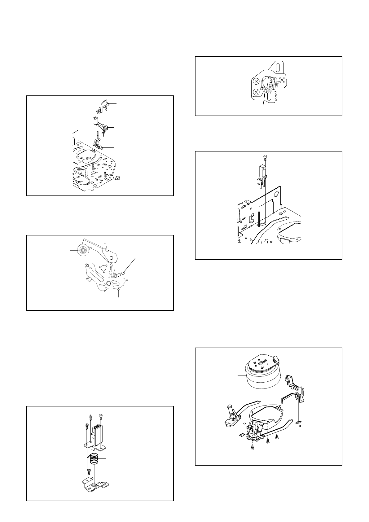
2-11: A/C HEAD (Refer to Fig. 2-11-A)
Remove the screw (1).
1.
Remove the A/C Head Base.
2.
Remove the 3 screws (2).
3.
Remove the A/C Head and A/C Head Spring.
4.
NOTE
1.
Do not touch the A/C Head. (Use gloves.)
2.
When you install the A/C Head Spring, install as shown
in Fig. 2-11-B.
3.
When you install the A/C Head, tighten the screw (1) first,
then tighten the screw (2), finally tighten the screw (3).
(3)
(1)
(2)
(2)
(2)
(1)
(2)
A/C Head
A/C Head Spring
Spring Position
Fig. 2-11-B
2-12: FE HEAD (RECORDER ONLY) (Refer to Fig. 2-12)
Remove the screw (1).
1.
Remove the FE Head.
2.
(1)
FE Head
• Screw Torque: 5 ± 0.5kgf•cm
• The FE Head is not installed on the Video Cassette Player.
Fig. 2-12
2-13:AHC ASS'Y/CYLINDER UNIT ASS'Y
(Refer to Fig. 2-13)
Unlock the support (1) and remove the AHC Ass'y.
1.
Disconnect the following connector: (CD2001)
2.
Remove the 3 screws (2).
3.
Remove the Cylinder Unit Ass'y.
4.
NOTE
When you install the Cylinder Unit Ass'y, tighten the
1.
screws from (1) to (3) in order while pulling the Ass'y
toward the left front direction.
Cylinder Unit Ass'y
AHC Ass'y
(1)
(3)
(2)
(1)
• Screw Torque: 3 ± 0.5kgf•cm
(2)
(2)
(2)
Fig. 2-13
• Screw Torque: 5 ± 0.5kgf•cm (Screw (1))
A/C Head Base
Fig. 2-11-A
B2-4
DISASSEMBLY INSTRUCTIONS
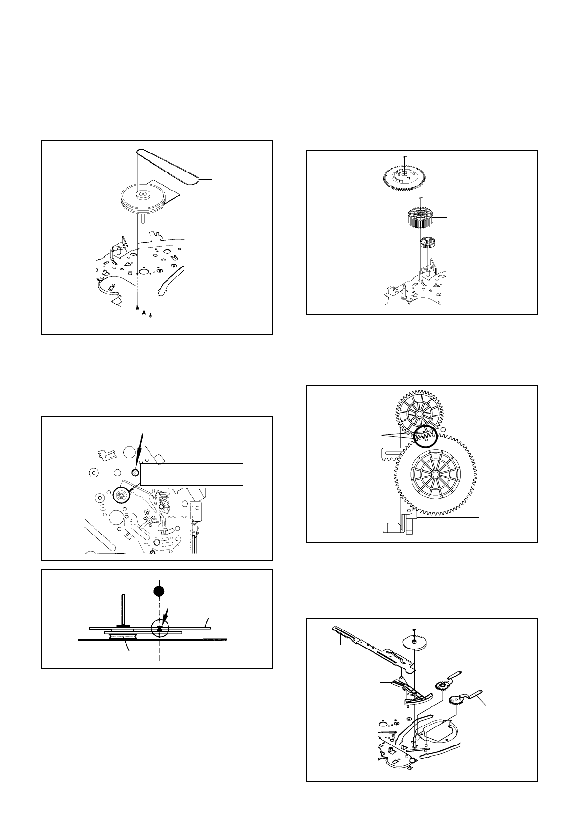
2-14: CAPSTAN DD UNIT (Refer to Fig. 2-14-A)
Remove the Capstan Belt.
1.
Remove the 3 screws (1).
2.
Remove the Capstan DD Unit.
3.
2-15:
MAIN CAM/PINCH ROLLER CAM/JOINT GEAR
(Refer to Fig. 2-15-A)
Remove the E-Ring (1), then remove the Main Cam.
1.
Remove the E-Ring (2), then remove the Pinch Roller
2.
Cam and Joint Gear.
(1)
Capstan Belt
Capstan DD Unit
(1)
(1)
• Screw Torque: 4 ± 0.5kgf•cm
(1)
Fig. 2-14-A
NOTE
In case of the Capstan DD Unit installation, apply the
1.
silicon bond (TSE3843-W) on the position Fig. 2-14-B
correctly. (If no silicon bond applied, abnormal noise will
be heard on the deck operation.)
(Refer to Fig. 2-14-B, C)
Applied position of
silicon bond
Main Cam
(2)
Pinch Roller Cam
Joint Gear
Fig. 2-15-A
NOTE
In case of the Pinch Roller Cam and Main Cam
1.
installation, install them as the circled section of Fig. 215-B so that the each markers are met. (Refer to Fig.
2-15-B)
Pinch Roller Cam
Marker
Capstan DD Unit
Be careful not to apply the silicon
bond to the Pinch Roller.
Fig. 2-14-B
Silicon Bond
Main Chassis
Fig. 2-14-C
Main Cam
Fig. 2-15-B
2-16: LOADING GEAR S/T UNIT (Refer to Fig. 2-16-A)
1.2.Remove the E-Ring (1) and remove the Main Loading
Gear.
Remove the Main Rod, Tension Lever, Loading Arm S
Unit and Loading Arm T Unit.
(1)
Main Rod
Tension Lever
Main Loading Gear
Loading Arm T Unit
Loading Arm S Unit
B2-5
Fig. 2-16-A
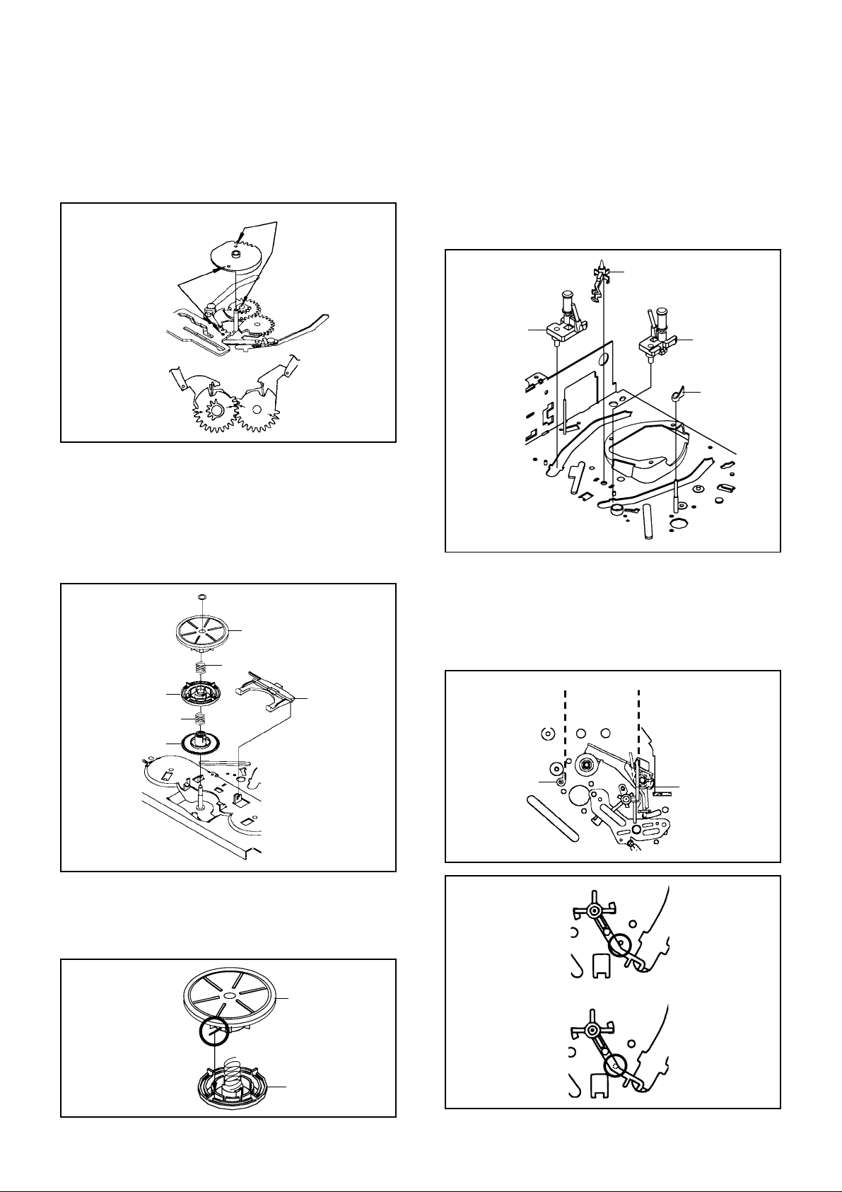
DISASSEMBLY INSTRUCTIONS
NOTE
When you install the Loading Arm S Unit, Loading Arm
1.
T Unit and Main Loading Gear, align each marker.
(Refer to Fig. 2-16-B)
Marker
Main Loading Gear
Marker
CASSETTE GUIDE POST/INCLINED BASE S/T
2-18:
UNIT/P4 CAP (Refer to Fig. 2-18-A)
Remove the P4 Cap.
1.
Unlock the support (1) and remove the Cassette Guide
2.
Post.
Remove the Inclined Base S Unit and Inclined Base T
3.
Unit.
(1)
Cassette Guide Post
Loading Arm T Unit
2-17:
CLUTCH ASS'Y/RING SPRING/CLUTCH LEVER/
Loading Arm S Unit
CLUTCH GEAR (Refer to Fig. 2-17-A)
Remove the Polyslider Washer (1).
1.
Remove the Clutch Ass'y and Ring Spring.
2.
Remove the Clutch Lever.
3.
Remove the Coupling Gear, Coupling Spring and
4.
Clutch Gear.
(1)
Clutch Ass'y
Ring Spring
Coupling Gear
Coupling Spring
Clutch Lever
Fig. 2-16-B
Inclined Base S
Unit
Inclined Base T
Unit
P4 Cap
Fig. 2-18-A
NOTE
Do not touch the roller of Guide Roller.
1.
In case of the P4 Cap installation, install it with parallel
2.
for "A" and "B" of Fig. 2-18-B.
In case of the Cassette Guide Post installation, install
3.
correctly as the circled section of Fig. 2-18-C.
"A"
"B"
Clutch Gear
Fig. 2-17-A
NOTE
In case of the Clutch Ass'y installation, install it with
1.
inserting the spring of the Clutch Ass'y into the dent of
the Coupling Gear. (Refer to Fig. 2-17-B)
Clutch Ass'y
Coupling Gear
Fig. 2-17-B
B2-6
P4 Cap
[OK]
Cassette Guide Post
[NG]
Cassette Guide Post
Cassette Opener
Fig. 2-18-B
Fig. 2-18-C

DISASSEMBLY INSTRUCTIONS
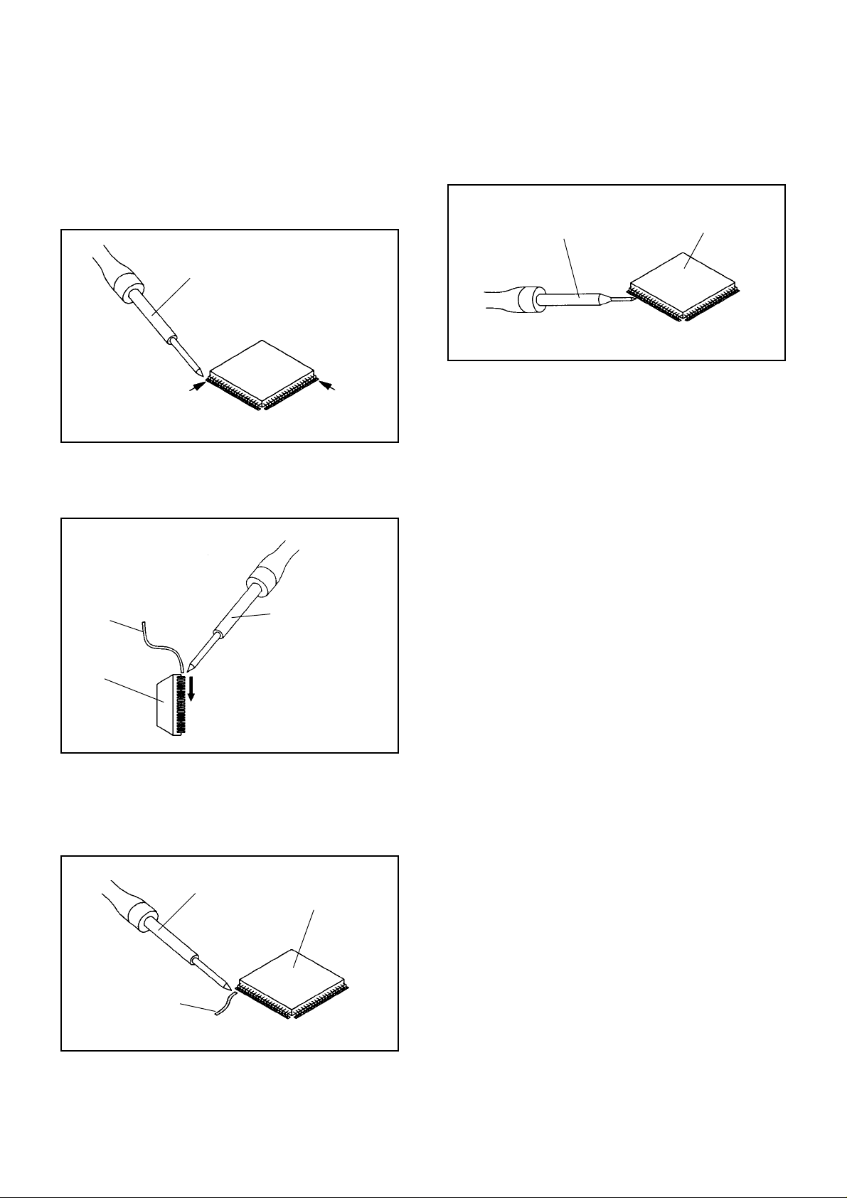
3.
REMOVAL AND INSTALLATION OF
FLAT PACKAGE IC
REMOVAL
Put the Masking Tape (cotton tape) around the Flat
1.
Package IC to protect other parts from any damage.
(Refer to Fig. 3-1.)
NOTE
Masking is carried out on all the parts located within
10 mm distance from IC leads.
When IC starts moving back and forth easily after
3.
desoldering completely, pickup the corner of the IC using
a tweezers and remove the IC by moving with the IC
desoldering machine. (Refer to Fig. 3-3.)
NOTE
Some ICs on the PCB are affixed with glue, so be
careful not to break or damage the foil of each IC
leads or solder lands under the IC when removing it.
Blower type IC
desoldering
machine
Masking Tape
(Cotton Tape)
Heat the IC leads using a blower type IC desoldering
2.
IC
machine. (Refer to Fig. 3-2.)
NOTE
Do not add the rotating and the back and forth
directions force on the IC, until IC can move back and
forth easily after desoldering the IC leads completely.
Blower type IC
desoldering machine
Fig. 3-1
Tweezers
IC
Peel off the Masking Tape.
4.
Absorb the solder left on the pattern using the Braided
5.
Shield Wire. (Refer to Fig. 3-4.)
NOTE
Do not move the Braided Shield Wire in the vertical
direction towards the IC pattern.
Fig. 3-3
Braided Shield Wire
Soldering Iron
IC
IC pattern
Fig. 3-4
Fig. 3-2
B3-1
DISASSEMBLY INSTRUCTIONS
INSTALLATION
Take care of the polarity of new IC and then install the
1.
new IC fitting on the printed circuit pattern. Then solder
each lead on the diagonal positions of IC temporarily.
(Refer to Fig. 3-5.)
Soldering Iron
Solder temporarily
Supply the solder from the upper position of IC leads
2.
Solder temporarily
sliding to the lower position of the IC leads.
(Refer to Fig. 3-6.)
Fig. 3-5
When bridge-soldering between terminals and/or the
4.
soldering amount are not enough, resolder using a Thintip Soldering Iron. (Refer to Fig. 3-8.)
Thin-tip Soldering Iron
IC
Fig. 3-8
Finally, confirm the soldering status on four sides of the
5.
IC using a magnifying glass.
Confirm that no abnormality is found on the soldering
position and installation position of the parts around the
IC. If some abnormality is found, correct by resoldering.
NOTE
When the IC leads are bent during soldering and/or
repairing, do not repair the bending of leads. If the
bending of leads are repaired, the pattern may be
damaged. So, be always sure to replace the IC in this
case.
Soldering IronSolder
IC
Absorb the solder left on the lead using the Braided
3.
Supply soldering
from upper position
to lower position
Shield Wire. (Refer to Fig. 3-7.)
NOTE
Do not absorb the solder to excess.
Soldering Iron
IC
Braided Shield Wire
Fig. 3-6
Fig. 3-7
B3-2

A
A/C
ACC
AE
AFC
AFT
AFT DET
AGC
AMP
ANT
A.PB
APC
ASSíY
AT
AUTO
A/V
B
BGP
BOT
BPF
BRAKE SOL
BUFF
B/W
C
C
CASE
CAP
CARR
CH
CLK
CLOCK (SY-SE)
COMB
CONV
CPM
CTL
CYL
CYL-M
CYL SENS
D
DATA (SY-CE)
dB
DC
DD Unit
DEMOD
DET
DEV
E
E
EF
EMPH
ENC
ENV
EOT
EQ
EXT
F
F
FBC
FE
FF
FG
FL SW
FM
FSC
FWD
G
GEN
GND
H
H.P.F
KEY TO ABBREVIATIONS
:
Audio/Control
:
Automatic Color Control
:
Audio Erase
:
Automatic Frequency Control
:
Automatic Fine Tuning
:
Automatic Fine Tuning Detect
:
Automatic Gain Control
:
Amplifier
:
Antenna
:
Audio Playback
:
Automatic Phase Control
:
Assembly
:
All Time
:
Automatic
:
Audio/Video
:
Burst Gate Pulse
:
Beginning of Tape
:
Bandpass Filter
:
Brake Solenoid
:
Buffer
:
Black and White
:
Capacitance, Collector
:
Cassette
:
Capstan
:
Carrier
:
Channel
:
Clock
:
Clock (Syscon to Servo)
:
Combination, Comb Filter
:
Converter
:
Capstan Motor
:
Control
:
Cylinder
:
Cylinder-Motor
:
Cylinder-Sensor
:
Data (Syscon to Servo)
:
Decibel
:
Direct Current
:
Direct Drive Motor Unit
:
Demodulator
:
Detector
:
Deviation
:
Emitter
:
Emitter Follower
:
Emphasis
:
Encoder
:
Envelope
:
End of Tape
:
Equalizer
:
External
:
Fuse
:
Feed Back Clamp
:
Full Erase
:
Fast Forward, Flipflop
:
Frequency Generator
:
Front Loading Switch
:
Frequency Modulation
:
Frequency Sub Carrier
:
Forward
:
Generator
:
Ground
:
High Pass Filter
H.SW
Hz
I
IC
IF
IND
INV
K
KIL
L
L
LED
LIMIT AMP
LM, LDM
LP
L.P.F
LUMI.
M
M
MAX
MINI
MIX
MM
MOD
MPX
MS SW
N
NC
NR
O
OSC
OPE
P
PB
PB CTL
PB-C
PB-Y
PCB
P. CON
PD
PG
P-P
R
R
REC
REC-C
REC-Y
REEL BRK
REEL S
REF
REG
REW
REV, RVS
RF
RMC
RY
S
S. CLK
S. COM
S. DATA
SEG
SEL
SENS
SER
SI
SIF
SO
SOL
SP
STB
SW
:
Head Switch
:
Hertz
:
Integrated Circuit
:
Intermediate Frequency
:
Indicator
:
Inverter
:
Killer
:
Left
:
Light Emitting Diode
:
Limiter Amplifier
:
Loading Motor
:
Long Play
:
Low Pass Filter
:
Luminance
:
Motor
:
Maximum
:
Minimum
:
Mixer, mixing
:
Monostable Multivibrator
:
Modulator, Modulation
:
Multiplexer, Multiplex
:
Mecha State Switch
:
Non Connection
:
Noise Reduction
:
Oscillator
:
Operation
:
Playback
:
Playback Control
:
Playback-Chrominance
:
Playback-Luminance
:
Printed Circuit Board
:
Power Control
:
Phase Detector
:
Pulse Generator
:
Peak-to Peak
:
Right
:
Recording
:
Recording-Chrominance
:
Recording-Luminance
:
Reel Brake
:
Reel Sensor
:
Reference
:
Regulated, Regulator
:
Rewind
:
Reverse
:
Radio Frequency
:
Remote Control
:
Relay
:
Serial Clock
:
Sensor Common
:
Serial Data
:
Segment
:
Select, Selector
:
Sensor
:
Search Mode
:
Serial Input
:
Sound Intermediate Frequency
:
Serial Output
:
Solenoid
:
Standard Play
:
Serial Strobe
:
Switch
C1-1

S
SYNC
SYNC SEP
T
TR
TRAC
TRICK PB
TP
U
UNREG
V
V
VCO
VIF
VP
V .PB
VR
V.REC
VSF
VSR
VSS
V-SYNC
VT
X
XíTAL
Y
Y/C
KEY TO ABBREVIATIONS
:
Synchronization
:
Sync Separator, Separation
:
Transistor
:
Tracking
:
Trick Playback
:
Test Point
:
Unregulated
:
Volt
:
Voltage Controlled Oscillator
:
Video Intermediate Frequency
:
Vertical Pulse, Voltage Display
:
Video Playback
:
Variable Resistor
:
Video Recording
:
Visual Search Fast Forward
:
Visual Search Rewind
:
Voltage Super Source
:
Vertical-Synchronization
:
Voltage T uning
:
Crystal
:
Luminance/Chrominance
C1-2

SERVICE MODE LIST
This unit provided with the following SERVICE MODES so you can repair, examine and adjust easily.
To enter to the SERVICE MODE function, press and hold both buttons simultaneously on the main unit or on the main unit
and on the remote control for more than a standard time (second).
Set Key
CH UP
CH UP STOP 2
CH UP PLAY 2
CH DOWN POWER 2
Set Key
Set Key
FF 2
Standard Time
(seconds)
Standard Time
(seconds)
Operations
PLAY/REC total hours are displayed on the screen.
Refer to the “PREVENTIVE CHECKS AND SERVICE INTERVALS”
(CONFIRMA TION OF HOURS USED).
Can be checked of the INITIAL DATA of MEMORY IC.
Refer to the “WHEN REPLACING EEPROM (MEMORY) IC”.
Adjust the PG SHIFTER automatically.
Refer to the “ELECTRICAL ADJUSTMENT” (PG SHIFTER).
Initialization of the factory on VCR.
NOTE: Do not use this for the normal servicing.
If you set a factory initialization, the memories are reset such as
the clock setting, the channel setting, and PLAY/REC total hours.
VCR operation mode at no connection of DVD.
Refer to the “PREPARATION FOR SERVICING”
NOTE:
Although the DVD is connected, the DVD mode cannot be
selected.
OperationsRemocon Key
REC 8 2
Method Operations
Press the ATR button on the
remote control for more than
2 seconds during PLAY.
Make the short circuit
between the test point of
SERVICE and the GND.
Initialization of the factory on DVD.
NOTE: Do not use this for the normal servicing.
The function will only work without the setting of DVD disc at
DVD mode.
While pressing the Remocon Key for more than the Standard
Time, press the Set Key simultaneously.
Adjusting of the Tracking to the center position.
Refer to the “MECHANICAL ADJUSTMENT” (GUIDE ROLLER) and “ELECTRICAL
ADJUSTMENT” (PG SHIFTER).
The BOT, EOT, and the Reel Sensor do not work and the VCR deck can be operated
without a cassette tape.
Refer to the “PREPARATION FOR SERVICING”
C2-1
 Loading...