

Page 1
MT1132A
SERVICE MANUAL
COLOR TELEVISION RECEIVER
ORIGINAL
MFR’S VERSION A
Design and specifications are subject to change without notice.
Page 2
MT1132A
SER VICE MANUAL
COLOR TELEVISION RECEIVER
ORIGINAL 2
MFR’S VERSION P
MFR’S VERSION
A
F
K
P A34JXV70X53N45
PCB010
TMX494A
TMX494B
TECC1040PG32D
Pleas file the revision with the original version.
TU001
NJH3022U268
V801
A34AGT13X98(L)
Page 3
Change of CRT
ELECTRICAL REPLACEMENT PARTS LIST
MFR'S VERSION K MFR'S VERSION P
REF. NO.
! V801 098Q1404B2 CRT W/DY A34AGT13X98(L) 098Y1404B9 CRT W/DY A34JXV70X53N45
! R429 R655812R7J R,FUSE 2.7 OHM 1W R655812R2J R,FUSE 2.2 OHM 1W
C804 CS0KB04K2K CC 270 PF 50V B CS0KB04L2K CC 330 PF 50V B
C805 CS0KB04K2K CC 270 PF 50V B CS0KB04L2K CC 330 PF 50V B
C806 CS0KB04K2K CC 270 PF 50V B CS0KB04L2K CC 330 PF 50V B
! CP401 069X450029 CONNECTOR PCB SIDE B05B-DVS 069D450049 CONNECTOR PCB SIDE TD-50-5P
PCB010 A3J812A010
MAIN PCB's are not interchangeable.
PART NO. DESCRIPTION PART NO. DESCRIPTION
MAIN PCB ASS'Y (VERSION K)
TMX494B
A3J804C010
MAIN PCB ASS'Y (VERSION K)
TMX494B
Page 4

SPEC.NO.
O/R NO.
M3J8-12C
K193004
Page 5
MT1132A
SER VICE MANUAL
COLOR TELEVISION RECEIVER
ORIGINAL 1
MFR’S VERSION F, K
MFR’S VERSION
A
F
K
PCB010
TMX494A
TMX494B
TUNER
NJH3022U268
TECC1040PG32D
Design and specifications are subject to change without notice.
Page 6

ELECTRICAL ADJUSTMENTS
(MFR'S VERSION K)
2. BASIC ADJUSTMENTS
2-1: RF AGC DELAY
1.
Place the set with Aging Test for more than 15 minutes.
2.
Receive the VHF HIGH (63dB).
3.
Connect the digital voltmeter to R606.
4.
Activate the adjustment mode display of Fig. 1-1 and
press the channel button (02) on the remote control to
select "RF AGC DELAY".
5.
Press the VOL. UP/DOWN button on the remote
control until the digital voltmeter is 2.7 ± 0.05V.
Page 7
ELECTRICAL REPLACEMENT PARTS LIST
PCB VERSION UP
MFR'S VERSION A MFR'S VERSION F
REF. NO.
PCB010 A3J812A010 MAIN PCB ASS'Y (VERSION A) TMX494A A3J812A010 MAIN PCB ASS'Y (VERSION F) TMX494B
MAIN PCB's are interchangeable.
PART NO. DESCRIPTION PART NO. DESCRIPTION
Change of TUNER
MFR'S VERSION F MFR'S VERSION K
REF. NO.
! TU001 0145W00052 TUNER,VHF-UHF NJH3022U268 0145K00055 TUNER,VHF-UHF TECC1040PG32D
R622 R903N8121J RC 120 OHM 1/8W R903N8271J RC 270 OHM 1/8W
PCB010 A3J812A010 MAIN PCB ASS'Y (VERSION F) TMX494B A3J812A010 MAIN PCB ASS'Y (VERSION K) TMX494B
MAIN PCB's are interchangeable.
PART NO. DESCRIPTION PART NO. DESCRIPTION
Page 8

SPEC.NO.
O/R NO.
M3J8-12A
K163004
Page 9

MICON/TUNER
200mV 5ms/div
2
0.5V 20µs/div
WAVEFORMS
61
0.5V 20µs/div
200mV 20µs/div
7
1V 20µs/div
11
1V 20µs/div
12
200mV 20µs/div
200mV 5ms/div
4
CHROMA
5
0.5V 2ms/div
20V 20µs/div3
8
200mV 20µs/div
9
0.5V 5ms/div
10
1V 20µs/div13
DEFLECTION/CRT
0.5V 5ms/div
14
20V 20µs/div
15
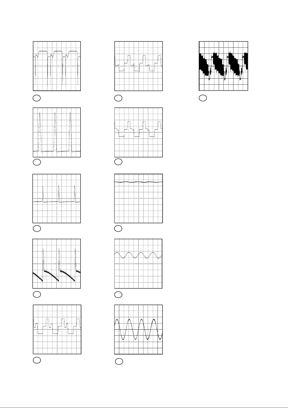
NOTE: The following waveforms were measured at the point of the corresponding
balloon number in the schematic diagram.
H-1
Page 10
WAVEFORMS
16 2V 20µs/div 21 50V 20µs/div
200V 20µs/div
17
22 50V 20µs/div
SOUND/AV
23
10V 5ms/div18
0.5V 1ms/div
26 500mV 20us/div
19
10V 5ms/div
50V 20µs/div
20
1V 1ms/div24
25 500mV 1ms/div
NOTE: The following waveforms were measured at the point of the corresponding
balloon number in the schematic diagram.
H-2
Page 11
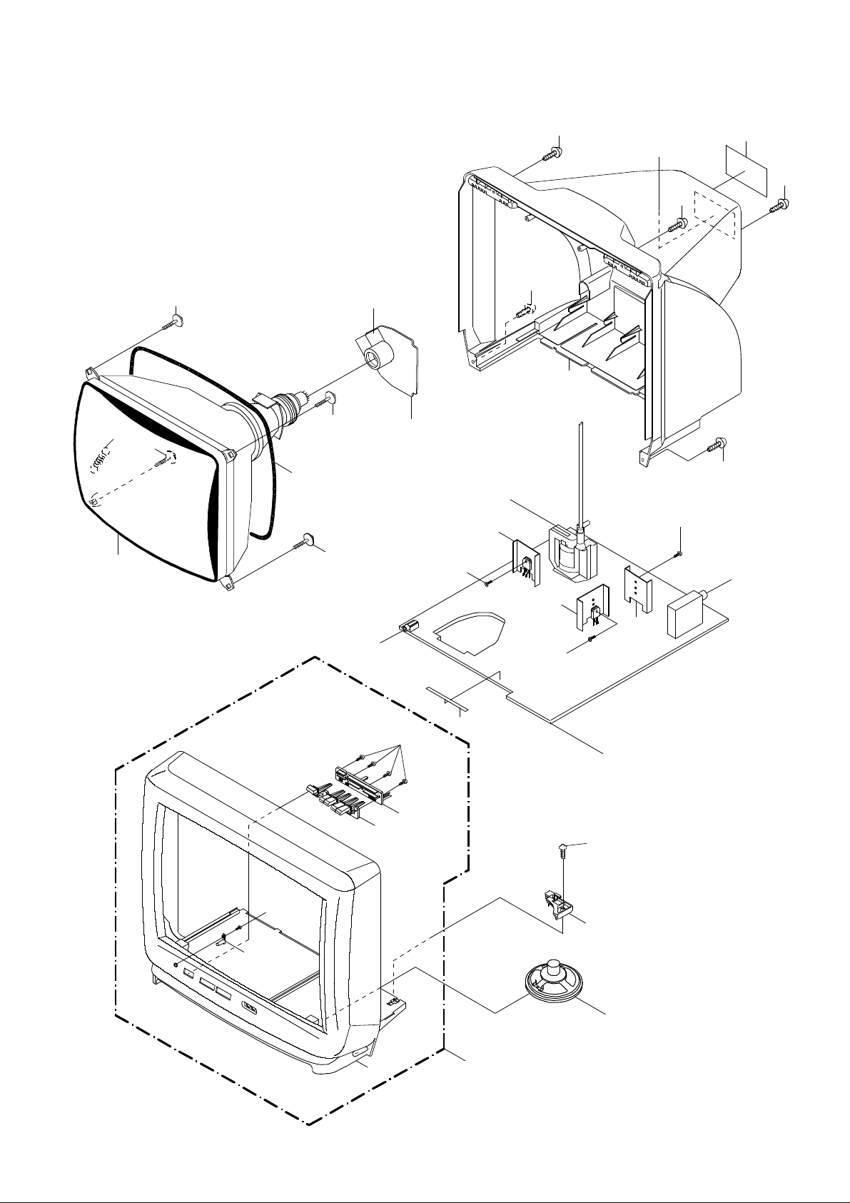
MECHANICAL EXPLODED VIEW
108
203
203
L503
203
J801
PCB110
(CRT PCB)
FB401
110
201
201
111
112
107
201
201
201
204
V801
103
202
203
J352
104
202
105
204
109
TU001
110
110
204
PCB010
(MAIN PCB)
202
106
102
SP351
101
I-1
Page 12

MECHANICAL REPLACEMENT PARTS LIST
REF. NO. PART NO. DESCRIPTION
101 A3J812A720CABINET,FRONT ASS'Y
102 701WPJB186CABINET,FRONT
103 713WPAA020GUIDE,REMOCON
104 735WPAA122BUTTON,FRAME
105 735WPAA121BUTTON,HOLDER
106 735WPA0396SPEAKER,HOLDER
107 726000A016SHEET,CRT SERVICEMAN
108 741WUA0019SPRING,EARTH
109 800WQ00044FELT SHEET 5x50xT0.5
110 --- HEAT SINK
111 702WPAA134CABINET,BACK
112 722A08A072SHEET,RATING
201 8117540A64SCREW,TAPPING (B0) TRUSS 4x16
202 8110630A04SCREW,TAP TITE (P) BRAZIER 3x10
203 8121J50B54SCREW,TAPPING (B0) GW20 5x28
204 8109I30A04 SCREW,TAP TITE(B) WH7 3x10
--- JB5U0200 POLY & BAG
--- J3J81201 INSTRUCTION BOOK
--- J4C80417 REGISTRATION CARD
--- 793WCDA919GIFT BOX
--- 791WHA0023LAMIFILM BAG
--- 792WHAA018PACKAGE,BOTTOM
--- 792WHAA019PACKAGE,TOP
J1-1
Page 13

ELECTRICAL REPLACEMENT PARTS LIST
REF. NO.PART NO. DESCRIPTION REF. NO.PART NO. DESCRIPTION
RESISTORS DIODES
!R401 R4X5T4104F R, METAL 100K OHM 1/4W D602 D97U08R21BDIODE, ZENER MTZJ8.2B T-77
!R405 R4X5T4183F R, METAL 18K OHM 1/4W D605 D2WT011E10DIODE, SILICON 11E1-EIC
!R406 R903N8102J RC 1K OHM 1/8W D610 D97U01201BDIODE, ZENER MTZJ12B T-77
!R407 R002T22R2J RC 2.2 OHM 1/2W D611 D97U01201BDIODE, ZENER MTZJ12B T-77
!R408 R4X5T6153F R, METAL 15K OHM 1/6W D612 D97U01201BDIODE, ZENER MTZJ12B T-77
!R409 R4X5T6123F R, METAL 12K OHM 1/6W
R423 R001T6471J RC 470 OHM 1/6W IC101 I56F07045B IC OEC7045B
!R426 R002T4272J RC 2.7K OHM 1/4W IC199 A3J802A015IC S-24C02BDP-1A
!R429 R655812R7J R, FUSE 2.7 OHM 1W !IC351 I01DP75110IC AN7511
!R500 R0G3K2275KRC 2.7M OHM 1/2W !IC401 I01TD55220IC AN5522
!R501 R5X2CD5R6JR, CEMENT 5.6 OHM 5W IC601 I06FC61206IC M61206FP
!R504 R3X28B330J R, METAL OXIDE 33 OHM 3W
!R505 R3X181221J R, METAL OXIDE 220 OHM 1W !Q401 TD30026270TRANSISTOR, SILICON 2SD2627LS-CBC11
R509 R903N8222J RC 2.2K OHM 1/8W !Q402 TCKT1473AQTRANSISTOR, SILICON 2SC1473A-Q-TA
R515 R002T2683J RC 68K OHM 1/2W !Q501 T25FK26620TRANSISTOR, FIELD EFFECT2SK2662
!R517 R3X1811R2J R, METAL 1.2 OHM 1W !Q502 TCAT032034TRANSISTOR, SILICON KTC3203_Y-AT
!R518 R4X5T6222F R, METAL 2.2K OHM 1/6W !Q504 0002E00610PHOTO COUPLER LTV-817M-V
!R519 R903N8122J RC 1.2K OHM 1/8W Q507 TCATC31980TRANSISTOR, SILICON KTC3198-AT(Y,GR)
!R542 R3X181R68J R, METAL OXIDE 0.68 OHM 1W Q603 TCAT032034TRANSISTOR, SILICON KTC3203_Y-AT
!R629 R3X28B330J R, METAL OXIDE 33 OHM 3W Q604 TCAT032034TRANSISTOR, SILICON KTC3203_Y-AT
!R641 R002T4223J RC 22K OHM 1/4W Q605 TCAT032034TRANSISTOR, SILICON KTC3203_Y-AT
R647 R001T6202J RC 2K OHM 1/6W Q606 TCAT032034TRANSISTOR, SILICON KTC3203_Y-AT
!R803 R3X181153J R, METAL OXIDE 15K OHM 1W !Q801 TCKT1473A0TRANSISTOR, SILICON 2SC1473A-TA-(RQ)
!R805 R3X181153J R, METAL OXIDE 15K OHM 1W !Q802 TCKT1473A0TRANSISTOR, SILICON 2SC1473A-TA-(RQ)
!R807 R3X181153J R, METAL OXIDE 15K OHM 1W !Q803 TCKT1473A0TRANSISTOR, SILICON 2SC1473A-TA-(RQ)
ICS
TRANSISTORS
CAPACITORS COILS &TRANSFORMERS
C402 P3N1F2123J CPP 0.012 UF 200V L101 021LA63R3KCOIL 3.3 UH
!C403 E02LT4471MCE 470 UF 35V L402 02186G180MCOIL 18 UH
!C414 E02LT4101MCE 100 UF 35V !L501 029T00A7M1COIL, LINE FILTER 1R5A102F20
!C418 E02LT3471MCE 470 UF 25V !L503 028R140030COIL, DEGAUSS 8R140030
!C434 E02LT8220MCE 22 UF 100V L601 0216731R2KCOIL 1.2 UH
C437 P4J7F3474J CMPP 0.47 UF 250V PMS L605 02167F1R0KCOIL 1 UH
C442 C0JLYR7H2KCC 220 PF 2KV YR L606 021LA62R2KCOIL 2.2 UH
!C443 P4N8FJ472HCMPP 0.0047UF 1.25KV L607 021LA6150KCOIL 15 UH
!C446 E02LT5220MCE 22 UF 50V L801 02167F101JCOIL 100 UH
!C448 E5EZTC220MCE 22 UF 200V T401 03305Y0018TRANS, HORIZONTAL DRIVE305Y001
C503 C0JTB0513K CC 0.001 UF 500V B !T502 0481290264TRANSFORMER, SWITCHING81290264
!C505 P2122B104MCMP 0.1 UF 250V ECQUL
!C506 CB3LF0M14MCC 0.01 UF 250V !J352 0602121012JACK, RCA 3.5 HSJ1403-01-010
!C508 CB3LF0M14MCC 0.01 UF 250V J702 060Q401077RCA, JACK AV1-09D-3
!C511 E02LU5010MCE 1 UF 50V J703 060Q401076RCA, JACK AV1-09D-4
C514 C0JLYR7U2KCC 680 PF 2KV YR !J801 066X120014SOCKET, CRT HPS3200-10501
!C515 E02LT2471MCE 470 UF 16V
C517 C0JLYR7Q2KCC 470 PF 2KV YR SW101 0504201T31SWITCH, TACT SKHVBED010 or
!C519 E02LT2471MCE 470 UF 16V 0504101T34SWITCH, TACT EVQ21505R
!C521 E5EZFB101MCE 100 UF 160V SW102 0504201T31SWITCH, TACT SKHVBED010 or
!C526 E02LFC221MCE 220 UF 200V 0504101T34SWITCH, TACT EVQ21505R
C602 CQGTF0414ZCC 0.01 UF 50V F SW103 0504201T31SWITCH, TACT SKHVBED010 or
C819 C0JBB0713KCC 0.001 UF 2KV B 0504101T34SWITCH, TACT EVQ21505R
DIODES
D001 D97U03001BDIODE, ZENER MTZJ30B T-77 0504101T34SWITCH, TACT EVQ21505R
!D401 D97U02701BDIODE, ZENER MTZJ27B T-77 SW105 0504201T31SWITCH, TACT SKHVBED010 or
!D402 D97U01101BDIODE, ZENER MTZJ11B T-77 0504101T34SWITCH, TACT EVQ21505R
D403 D2WT011E10DIODE, SILICON 11E1-EIC
D404 D97U06R21BDIODE, ZENER MTZJ6.2B T-77 PCB010 A3J812A01APCB ASS'Y TMX494A
!D405 D2WTAU02A0DIODE, SILICON AU02A-EIC PCB110 A3J812A11APCB ASS'Y TCX352A
!D406 D1VT001330 DIODE, SILICON 1SS133T-77
D408 D2WT011E10DIODE, SILICON 11E1-EIC !ANT001 125C108030ANTENNA, ROD HPAS-2S780
D410 D2WTAU02A0DIODE, SILICON AU02A-EIC CD351 06CH122301CORD, CONNECTOR CH122301
!D411 D2WTAU02A0DIODE, SILICON AU02A-EIC !CD501 120R414903CORD, AC 0R414903
!D501 D2WXN40050DIODE, SILICON 1N4005-EIC CF601 1022T45R72FILTER, SAW SAF45MFY220ZR
!D502 D2WXN40050DIODE, SILICON 1N4005-EIC CF603 1011T4R504FILTER, CERAMIC EFCT4R5YS5A
!D503 D2WXN40050DIODE, SILICON 1N4005-EIC CF604 1011T4R517FILTER, CERAMIC EFCT4R5MW5
!D504 D2WXN40050DIODE, SILICON 1N4005-EIC !CP401 069X450029CONNECTOR PCB SIDE B05B-DVS
!D505 D2WXB290S0DIODE, SILICON SB290S !CP502 069W420029CONNECTOR PCB SIDE TV-50P-02-A1 or
D506 D97U01501BDIODE, ZENER MTZJ15B T-77 069S420110CONNECTOR PCB SIDE A1561WV2-2P
D507 D97U01501BDIODE, ZENER MTZJ15B T-77 CP601 0694260139CONNECTOR PCB SIDE 173979-6
D508 D1VT001330 DIODE, SILICON 1SS133T-77 CP801 069W010030CONNECTOR PCB SIDE TBS-X01X-A1
!D509 D97U01801BDIODE, ZENER MTZJ18B T-77 CP802A 067R010019WIRE HOLDER 51048-1000 or
!D510 D2WXRU2AM0DIODE, SILICON RU2AM-EIC 067N010039WIRE HOLDER 9253_010_000_000 or
D512 D1VT001330 DIODE, SILICON 1SS133T-77 067U010049WIRE HOLDER B2013H02-10P
!D513 D2WXB290S0DIODE, SILICON SB290S CP802B 067R010019WIRE HOLDER 51048-1000 or
D514 D1VT001330 DIODE, SILICON 1SS133T-77 067N010039WIRE HOLDER 9253_010_000_000 or
D518 D1VT001330 DIODE, SILICON 1SS133T-77 067U010049WIRE HOLDER B2013H02-10P
D519 D1VT001330 DIODE, SILICON 1SS133T-77 !F501 081PC04004FUSE 51MS040LCC
D528 D97U05R61BDIODE, ZENER MTZJ5.6B T-77 !FB401 043214029FTRANSFORMER, FLYBACK 3214029F
D601 D1VT001330 DIODE, SILICON 1SS133T-77 FH501 06710T0006HOLDER, FUSE EYF-52BC
SW104 0504201T31SWITCH, TACT SKHVBED010 or
P.C.BOARD ASSEMBLIES
JACKS
SWITCHES
MISCELLANEOUS
J2-1
Page 14

ELECTRICAL REPLACEMENT PARTS LIST
REF. NO.PART NO. DESCRIPTION
MISCELLANEOUS
FH502 06710T0006 HOLDER, FUSE EYF-52BC
OS101 077Q014003 REMOTE RECEIVER PIC-28143SY-2
!SP351 070Y132018 SPEAKER S08F21
!TH501 DF5EL3R0A0DEGAUSS, ELEMENT ZPB45BL3R0A
TM101 076N0DW010TRANSMITTER RC-DW010
!TU001 0145W00052 TUNER, VHF-UHF NJH3022U268
!V801 098Q1404B2 CRT W/DY A34AGT13X98(L)
X101 1001T8R004 CERAMIC, OSCILLATOR EFOEC8004T4
X602 100CT3R505 CRYSTAL HC-49/C 3.579545MHz
RESISTOR
CAPACITORS
RC...................CARBON RESISTOR
CC...................CERAMIC CAPACITOR
CE................... ALUMI ELECTROLYTIC CAPACITOR
CP................... POLYESTER CAPACITOR
CPP..................POLYPROPYLENE CAPACITOR
CPL..................PLASTIC CAPACITOR
CMP..................
CMPL................METAL PLASTIC CAPACITOR
CMPP................METAL POLYPROPYLENE CAPACITOR
.METAL POLYESTER CAPACITOR
J2-2
Page 15

SPEC.NO.
O/R NO.
M3J8-12A
K123003
Page 16

SERVICING NOTICES ON CHECKING
As for the places which need special attentions,
they are indicated with the labels or seals on the
cabinet, chassis and parts. Make sure to keep the
indications and notices in the operation manual.
2. AVOID AN ELECTRIC SHOCK
There is a high voltage part inside. Avoid an
electric shock while the electric current is
flowing.
3. USE THE DESIGNATED PARTS
The parts in this equipment have the specific
characters of incombustibility and withstand
voltage for safety. Therefore, the part which is
replaced should be used the part which has
the same character.
Especially as to the important parts for safety
which is indicated in the circuit diagram or the
table of parts as a mark, the designated
parts must be used.
PUT PARTS AND WIRES IN THE
4.
ORIGINAL POSITION AFTER
ASSEMBLING OR WIRING
There are parts which use the insulation
material such as a tube or tape for safety, or
which are assembled in the condition that
these do not contact with the printed board.
The inside wiring is designed not to get closer
to the pyrogenic parts and high voltage parts.
Therefore, put these parts in the original
positions.
5.TAKE CARE TO DEAL WITH THE
CATHODE-RAY TUBE
In the condition that an explosion-proof cathoderay tube is set in this equipment, safety is
secured against implosion. However, when
removing it or serving from backward, it is
dangerous to give a shock. Take enough care to
deal with it.
6. AVOID AN X-RAY1. KEEP THE NOTICES
Safety is secured against an X-ray by considering about the cathode-ray tube and the high
voltage peripheral circuit, etc.
Therefore, when repairing the high voltage peripheral circuit, use the designated parts and
make sure not modify the circuit.
Repairing except indicates causes rising of high
voltage, and it emits an X-ray from the cathoderay tube.
7.PERFORM A SAFETY CHECK AFTER
SERVICING
Confirm that the screws, parts and wiring which
were removed in order to service are put in the
original positions, or whether there are the
portions which are deteriorated around the
serviced places serviced or not. Check the
insulation between the antenna terminal or
external metal and the AC cord plug blades.
And be sure the safety of that.
(INSULATION CHECK PROCEDURE)
1.
Unplug the plug from the AC outlet.
2.
Remove the antenna terminal on TV and turn
on the TV.
3.
Insulation resistance between the cord plug
terminals and the eternal exposure metal
[Note 2] should be more than 1M ohm by
using the 500V insulation resistance meter
[Note 1].
4.
If the insulation resistance is less than 1M
ohm, the inspection repair should be
required.
[Note 1]
If you have not the 500V insulation
resistance meter, use a Tester.
[Note 2]
External exposure metal:Antenna terminal
Earphone jack
HOW TO ORDER PARTS
Please include the following informations when you order parts. (Particularly the VERSION LETTER.)
1.MODEL NUMBER and VERSION LETTER
The MODEL NUMBER can be found on the back of each product and the VERSION LETTER can be
found at the end of the SERIAL NUMBER.
2.PART NO. and DESCRIPTION
You can find it in your SERVICE MANUAL.
IMPORTANT
Inferior silicon grease can damage IC's and transistors.
When replacing an IC's or transistors, use only specified silicon grease (YG6260M).
Remove all old silicon before applying new silicon.
A1-1
Page 17

CONTENTS
SERVICING NOTICES ON CHECKING......................................................................................................
HOW TO ORDER PARTS ...........................................................................................................................
IMPORTANT................................................................................................................................................
CONTENTS .................................................................................................................................................
GENERAL SPECIFICATIONS ....................................................................................................................
DISASSEMBLY INSTRUCTIONS ...............................................................................................................
SERVICE MODE LIST.................................................................................................................................
CONFIRMATION OF USING HOURS.........................................................................................................
NOTE FOR THE REPLACING OF MEMORY IC ........................................................................................
ELECTRICAL ADJUSTMENTS ..................................................................................................................
MAJOR COMPONENTS LOCATION GUIDE .............................................................................................
BLOCK DIAGRAM ......................................................................................................................................
PRINTED CIRCUIT BOARDS
MAIN/CRT..........................................................................................................................................
SCHEMATIC DIAGRAMS
MICON/TUNER..................................................................................................................................
CHROMA ...........................................................................................................................................
TV POWER ........................................................................................................................................
DEFLECTION/CRT ............................................................................................................................
SOUND/AV ........................................................................................................................................
WAVEFORMS .............................................................................................................................................
MECHANICAL EXPLODED VIEW ..............................................................................................................
MECHANICAL REPLACEMENT PARTS LIST ..........................................................................................
ELECTRICAL REPLACEMENT PARTS LIST ............................................................................................
A1-1
A1-1
A1-1
A2-1
A3-1~A3-4
B-1
C-1
C-1
C-1
D1-1~D2-1
D3-1
E-1, E-2
F-1~F-4
G-1, G-2
G-3, G-4
G-5, G-6
G-7, G-8
G-9, G-10
H-1, H-2
I-1
J1-1
J2-1, J2-2
A2-1
Page 18

GENERAL SPECIFICATIONS
G-1 TV CRT CRT Size / Visual Size 13 inch / 335.4mmV
G-2 Tuning Broadcasting System US System M
G-3 Power Power Source AC 120V AC 60Hz
G-4 Regulation Safety UL
G-5 Temperature Operation +5oC ~ +40oC
G-6 Operating Humidity Less then 80% RH
System CRT Type Normal
Deflection 90 degree
Magnetic Field BV/BH +0.45G/0.18G
Color System NTSC
Speaker 1Speaker
Position Bottom
Size 3 Inch
Impedance 8 ohm
Sound Output MAX 1.0W
10%(Typical) 0.8W
NTSC3.58+4.43 /PAL60Hz No
System Tuner and System 1Tuner
Receive CH Destination Ohers
Tuning System F-Synth
Input Impedance VHF/UHF 75 ohm
2 - 69, 4A, A-5 - A-I,
CH Coverage A - I, J - W, W+1 - W+84
Intermediate Picture(FP) 45.75MHz
Frequency Sound(FS) 41.25MHz
FP-FS 4.50MHz
Preset CH No
Stereo/Dual TV Sound No
Tuner Sound Muting Yes
DC
Power Consumption at AC
54 W at AC 120 V 60 Hz
Stand by (at AC) 5 W at AC 120 V 60 Hz
Per Year -- kWh/Year
Protector Power Fuse Yes
Radiation FCC
X-Radiation DHHS
Storage -20oC ~ +60oC
G-7 On Screen Menu Yes
Display Menu Type Character
Picture Yes
Contrast Yes
Brightness Yes
Color Yes
Tint Yes
Sharpness Yes
Audio No
Bass No
Treble No
Balance No
BBE On/Off No
Stable Sound On/Off No
CH Set Up Yes
TV/CATV Yes
Auto CH Memory Yes
Add/ Delete Yes
Language Yes
V-chip Yes
CH Label No
Favorite CH No
Color Stream DVD/DTV No
Control Level Yes
Sound Yes
Brightness Yes
Contrast Yes
Color Yes
Tint (NTSC Only) Yes
Sharpness Yes
Tuning No
Bass No
Treble No
Balance No
Back Light No
Stereo,Audio Output,SAP No
Video Yes
Color Stream No
A3-1
Page 19

GENERAL SPECIFICATIONS
Channel(TV/Cable) Yes
CH Label No
Sleep Timer Yes
Sound Mute Yes
G-8 OSD Language English French Spanish
G-9 Clock and Sleep Timer Max Time 120 Min
Timer Step 10 Min
On/Off Timer Program(On Tim / Off Tim) No
Wake Up Timer No
Timer Back-up (at Power Off Mode) more than -- Min Sec
V-chip Rating Yes
OSD Language Setting English
G-10 Remote Unit RC-DW
Control Glow in Dark Remocon No
Format NEC
Custom Code 86-05 h
Power Source Voltage(D.C) 3V
UM size x pcs UM-4 x 2 pcs
Total Keys 27 Keys
Keys Power Yes
1 Yes
2 Yes
3 Yes
4 Yes
5 Yes
6 Yes
7 Yes
8 Yes
9 Yes
0 Yes
100 No
CH Up Yes
CH Down Yes
Volume Up Yes
Volume Down Yes
TV/Caption/Text Yes
CH1/CH2 Yes
TV/Video(TV/AV) Yes
CH RTN/CH ENT(Quick View) Yes
Sleep Yes
RE Call(Call) Yes
Reset Yes
Menu Yes
Enter Yes
Mute Yes
Exit No
MTS(Audio Select) No
Set + Yes
Set - Yes
Multi Brand Keys CH Up(VCR) No
CH Down(VCR) No
Pause/Still No
TV/VCR(VCR) No
Code No
FF No
Rew No
Rec No
Play No
Stop No
TV No
VCR No
Cable No
G-11 Features Auto Degauss Yes
Auto Shut Off Yes
Canal+ No
CATV Yes
Anti-theft No
Rental No
Memory(Last CH) Yes
Memory(Last Volume) Yes
V-Chip Yes
Type USA,ORION Type
BBE No
Auto Search No
CH Allocation No
A3-2
Page 20

GENERAL SPECIFICATIONS
SAP No
Channel Lock No
Just Clock Function No
Game Position No
CH Label No
VM Circuit No
Full OSD No
Premiere No
Comb Filter No
Lines
Auto CH Memory Yes
Hotel Lock No
Closed Caption Yes
Stable Sound No
Favorite CH No
G-12 Accessories Owner's Manual Language English
w/Guarantee Card Yes
Remote Control Unit Yes
Rod Antenna Yes
Poles 1 Pole
Terminal F type
Loop Antenna
Terminal -
U/V Mixer
DC Car Cord (Center+)
Guarantee Card
Warning Sheet
Circuit Diagram
Antenna Change Plug
Service Facility List
Important Safeguard
Dew/AHC Caution Sheet
AC Plug Adapter
Quick Set-up Sheet
Battery
UM size x pcs
OEM Brand
AC Cord
AV Cord (2Pin-1Pin)
Registration Card Yes
PTB Sheet
300 ohm to 75 ohm Antenna Adapter
No
No
No
No
No
No
No
No
No
No
No
No
No
No
No
No
No
No
G-13 Interface Switch Front Power Yes
Rear AC/DC No
Indicator Power
Terminals Front Video Input
Rear Video Input(Rear1) No
G-14 Set Size Approx. W x D x H (mm) 362 x 361 x 320
G-15 Weight Net (Approx.) 9.5 kg
System Select No
Main Power SW No
Sub Power No
Channel Up/Reset Yes
Channel Down/Enter Yes
Volume Up/Set Up Yes
Volume Down/Set Down Yes
MENU=Volume Up+Volume Down Yes
TV/CATV Selector No
Degauss No
Main Power SW No
Stand-by
On Timer
Audio Input
Other Terminal
Video Input(Rear2) No
Audio Input(Rear1) No
Audio Input(Rear2) No
Video Output No
Audio Output No
Euro Scart No
Color Stream No
Diversity No
Ext Speaker No
DC Jack 12V(Center +) No
VHF/UHF Antenna Input
AC Outlet No
No
No
No
RCA
RCAx1
Ear Phone
F Type
( 20.9 lbs)
A3-3
Page 21

GENERAL SPECIFICATIONS
G-16 Carton Master Carton
Gift Box Yes
Drop Test
Container Stuffing
G-17 Cabinet Material Cabinet Front PS 94V0 DECABROM
Gross (Approx.) 11.0kg
Content ---Material --
Dimensions W x D x H(mm) -- x -- x --
Description of Origin
Material Double/Brown
Dimensions W x D x H(mm) 408 x 440 x 380
Design As per Buyer's
Description of Origin Yes
Height (cm) 62
866
Cabinet Rear PS 94V0 DECABROM
( 24.4lbs)
No
Sets
/--
No
Natural Dropping At 1 Corner /
ges / 6 Surfaces
3 Ed
Sets/40' container
A3-4
Page 22

DISASSEMBLY INSTRUCTIONS
1. REMOVAL OF ANODE CAP
Read the following NOTED items before starting work.
After turning the power off there might still be a potential
*
voltage that is very dangerous. When removing the
Anode Cap, make sure to discharge the Anode Cap's
potential voltage.
Do not use pliers to loosen or tighten the Anode Cap
*
terminal, this may cause the spring to be damaged.
REMOVAL
1. Follow the steps as follows to discharge the Anode Cap.
(Refer to Fig. 1-1.)
Connect one end of an Alligator Clip to the metal part of
a flat-blade screwdriver and the other end to ground.
While holding the plastic part of the insulated screwdriver,
touch the support of the Anode with the tip of the
screwdriver.
A cracking noise will be heard as the voltage is discharged.
GND on the CRT
3. After one side is removed, pull in the opposite direction to
remove the other.
NOTE
Take care not to damage the Rubber Cap.
INSTALLATION
1. Clean the spot where the cap was located with a small
amount of alcohol. (Refer to Fig. 1-3.)
Location of Anode Cap
Fig. 1-3
NOTE
Confirm that there is no dirt, dust, etc. at the spot where
the cap was located.
2.3.Arrange the wire of the Anode Cap and make sure the
wire is not twisted.
Turn over the Rubber Cap. (Refer to Fig. 1-4.)
Screwdriver
Alligator Clip
GND on the CRT
Flip up the sides of the Rubber Cap in the direction of the
2.
arrow and remove one side of the support.
(Refer to Fig. 1-2.)
Rubber Cap
CRT
Support
Support
CRT
Fig. 1-1
Fig. 1-2
Fig. 1-4
4. Insert one end of the Anode Support into the anode button,
then the other as shown in Fig. 1-5.
Support
CRT
5.6.Confirm that the Support is securely connected.
Put on the Rubber Cap without moving any parts.
Fig. 1-5
B-1
Page 23

SERVICE MODE LIST
This unit provided with the following SERVICE MODES so you can repair, examine and adjust easily.
To enter the Service Mode, press both set key and remote control key for more than 1 second.
Set Key
VOL. (-) MIN
VOL. (-) MIN 1
VOL. (-) MIN 6
VOL. (-) MIN 8
VOL. (-) MIN
Remocon Key
0
9
Releasing of V-CHIP PASSWORD.
Initialization of the factory.
NOTE: Do not use this for the normal servicing.
POWER ON total hours is displayed on the screen.
Refer to the "CONFIRMATION OF USING HOURS".
Can be checked of the INITIAL DATA of MEMORY IC.
Refer to the "NOTE FOR THE REPLACING OF MEMORY IC".
Writing of EEPROM initial data.
NOTE: Do not use this for the normal servicing.
Display of the Adjustment MENU on the screen.
Refer to the "ELECTRICAL ADJUSTMENT" (On-Screen Display Adjustment).
Operations
CONFIRMATION OF USING HOURS
POWER ON total hours can be checked on the screen. Total hours are displayed in 16 system of notation.
1.
Set the VOLUME to minimum.
2.
Press both VOL. DOWN button on the set and Channel
button (6) on the remote control for more than 1 second.
3.
After the confirmation of using hours, turn off the power.
ADDRESS DATA
INIT 00 83
CRT ON
0010
FIG. 1
Initial setting content of MEMORY IC.
POWER ON total hours.
= (16 x 16 x 16 x thousands digit value)
+ (16 x 16 x hundreds digit value)
+ (16 x tens digit value)
+ (ones digit value)
NOTE FOR THE REPLACING OF MEMORY IC
If a service repair is undertaken where it has been required to change the MEMORY IC, the following steps should be taken to
ensure correct data settings while making reference to TABLE 1.
ADDRESS
DATA
1.
Enter DATA SET mode by setting VOLUME to minimum.
2.
Press both VOL. DOWN button on the set and Channel button (6) on the remote control for more than 1 second.
ADDRESS and DATA should appear as FIG 1.
3.
ADDRESS is now selected and should "blink". Using the SET + or - keys on the remote, step through the ADDRESS until
required ADDRESS to be changed is reached.
4.
Press ENTER to select DATA. When DATA is selected, it will "blink".
5.
Again, step through the DATA using SET + or - until required DATA value has been selected.
6.
Pressing ENTER will take you back to ADDRESS for further selection if necessary.
7.
Repeat steps 3 to 6 until all data has been checked.
8.
When satisfied correct DATA has been entered, turn POWER off (return to STANDBY MODE) to finish DATA input.
The unit will now have the correct DATA for the new MEMORY IC.
INI00INI01INI02INI03INI04INI05INI06INI07INI08INI
88 09 A0 01 06 B3 24 19 21 20
Table 1
09
INI
0A
FF
C-1
Page 24

ELECTRICAL ADJUSTMENTS
1.
BEFORE MAKING ELECTRICAL
ADJUSTMENTS
Read and perform these adjustments when repairing the
circuits or replacing electrical parts or PCB assemblies.
CAUTION
•
Use an isolation transformer when performing any
service on this chassis.
•
Before removing the anode cap, discharge electricity
because it contains high voltage.
•
When removing a PCB or related component, after
unfastening or changing a wire, be sure to put the wire
back in its original position.
Inferior silicon grease can damage IC's and transistors.
•
When replacing IC's and transistors, use only specified
silicon grease (YG6260M).
Remove all old silicon before applying new silicon.
Prepare the following measurement tools for
electrical adjustments.
1. Synchro Scope
2. Digital Voltmeter
On-Screen Display Adjustment
In the condition of NO indication on the screen.
1.
Press the VOL. DOWN button on the set and the
Channel button (9) on the remote control for more than
1 second to appear the adjustment mode on the screen
as shown in Fig. 1-1.
TV
00 OSD 15
Fig. 1-1
Use the Channel UP/DOWN button or Channel button
2.
(0-9) on the remote control to select the options shown
in Fig. 1-2.
Press the MENU button on the remote control to end
3.
the adjustments.
2. BASIC ADJUSTMENTS
2-1: RF AGC DELAY
Place the set with Aging Test for more than 15 minutes.
1.
2.
Receive an 64dB monoscope pattern.
3.
Connect the digital voltmeter to R606.
4.
Activate the adjustment mode display of Fig. 1-1 and
press the channel button (02) on the remote control to
select "RF AGC DELAY".
5.
Press the VOL. UP/DOWN button on the remote control
until the digital voltmeter is 2.3V.
2-2: CUT OFF
1.
Adjust the unit to the following settings.
R.DRIVE=10, B.DRIVE=10, R.BIAS=64, G.BIAS=64,
B.BIAS=64, BRIGHTNESS=100, CONTRAST=64.
2.
Place the set with Aging Test for more than 15 minutes.
3.
Activate the adjustment mode display of Fig. 1-1 and
press the channel button (01) on the remote control to
select "CUT OFF".
4.
Adjust the Screen Volume until a dim raster is obtained.
2-3: FOCUS
1.
Receive the monoscope pattern.
2.
Turn the Focus Volume fully counterclockwise once.
3.
Adjust the Focus Volume until picture is distinct.
2-4: WHITE BALANCE
NOTE: Adjust after performing CUT OFF adjustment.
Place the set with Aging Test for more than 10 minutes.
1.
Receive the white 100% signal from the Pattern
2
Generator.
Using the adjustment control, set the brightness and
3.
contrast to normal position.
Activate the adjustment mode display of Fig. 1-1 and
4.
press the channel button (10) on the remote control to
select "R.BIAS".
Using the VOL. UP/DOWN button on the remote control,
5.
adjust the R.BIAS.
Press the CH. UP/DOWN button on the remote control to
6.
select the "R.DRIVE", "B.DRIVE", "G.BIAS" or "B.BIAS".
Using the VOL. UP/DOWN button on the remote control,
7.
adjust the R.DRIVE, B.DRIVE, G.BIAS or B.BIAS.
Perform the above adjustments 6 and 7 until the white
8.
color is looked like a white.
FUNCTION
NO.
OSD H
00
CUT OFF
01
RF AGC DELAY
02
VIF VCO
03
H VCO
04
H PHASE
05
V SIZE
06
V SHIFT
07
R DRIVE
08
B DRIVE
09
R BIAS
10
G BIAS
11
B BIAS
12
FUNCTION
NO.
BRIGHTNESS
13
CONTRAST
14
COLOR
15
TINT
16
SHARPNESS
17
FM LEVEL
18
LEVEL
19
SEPARATION 1
20
SEPARATION 2
21
TEST MONO
22
TEST STEREO
23
X-RAY TEST
24
Fig. 1-2
2-5: SUB TINT/SUB COLOR
1.
Receive the color bar pattern. (RF Input)
2.
Connect the synchro scope to TP023.
3.
Activate the adjustment mode display of Fig. 1-1 and
press the channel button (16) on the remote control to
select "TINT".
4.
Press the VOL. UP/DOWN button on the remote control
until the waveform becomes as shown in Fig. 2-1.
5.
Connect the synchro scope to TP022.
6.
Press the CH DOWN button once to set to "COLOR"
mode.
7.
Press the VOL. UP/DOWN button on the remote control
until the red color level is adjusted to 100% of the white
level. (Refer to Fig. 2-2)
8.
Receive the color bar pattern. (Audio Video Input)
9.
Press the TV/AV button on the remote control to set to
the AV mode. Then perform the above adjustments 2~7.
D1-1
Page 25

ELECTRICAL ADJUSTMENTS
2-9: OSD HORIZONTAL
1.2.Activate the adjustment mode display of Fig. 1-1.
Fig. 2-1
0%
110%
Press the VOL. UP/DOWN button on the remote control
until the difference of A and B becomes minimum.
(Refer to Fig. 2-3)
TV
00 OSD 15
A
B
Fig. 2-3
100%
Fig. 2-2
2-6: HORIZONTAL PHASE
1.
Receive the center cross signal from the Pattern
Generator.
2.
Activate the adjustment mode display of Fig. 1-1 and
press the channel button (05) on the remote control to
select "H.PHASE".
3.
Press the VOL. UP/DOWN button on the remote control
until the SHIFT quantity of the OVER SCAN on right
and left becomes minimum.
2-7: VERTICAL SIZE
NOTE: Adjust after performing adjustments in section 2-6
Receive the crosshatch signal from the Pattern
1.
Generator.
Activate the adjustment mode display of Fig. 1-1 and
2.
press the channel button (06) on the remote control to
select "V.SIZE".
Press the VOL. UP/DOWN button on the remote control
3.
until the rectangle on the center of the screen becomes
square.
Receive a broadcast and check if the picture is normal.
4.
2-8: VERTICAL SHIFT
NOTE: Adjust after performing adjustments in section 2-7
1.
Receive the crosshatch signal from the Pattern
Generator.
2.
Activate the adjustment mode display of Fig. 1-1 and
press the channel button (07) on the remote control to
select "V.SHIFT".
3.
Press the VOL. UP/DOWN button on the remote control
until the horizontal line becomes fit to the notch of the
shabow mask.
2-10: VIF VCO
Place the set with Aging Test for more than 10 minutes.
1.
Receive an 80dB monoscope pattern.
2.
Connect the digital voltmeter between the pin 5 of
3.
CP601 and the GND.
Activate the adjustment mode display of Fig. 1-1 and
4.
press the channel button (03) on the remote control to
select "VIF VCO".
Press the VOL. UP/DOWN button on the remote control
5.
until the digital voltmeter is 2.5V.
2-11: SUB BRIGHTNESS NORMAL
1.
Place the set with Aging Test for more than 15 minutes.
2.
Receive an 70 ~ 80dB monoscope pattern. (RF Input)
3.
Activate the adjustment mode display of Fig. 1-1 and
press the channel button (13) on the remote control to
select "BRIGHTNESS".
4.
Press the VOL. UP/DOWN button on the remote control
until the GLAY SCALE begin to shine.
5.
Place the set with Aging Test for more than 15 minutes.
6.
Receive an 70 ~ 80dB monoscope pattern. (Audio Video)
7.
Press the TV/AV button on the remote control to set to
the AV mode. Then perform the above adjustments 3, 4.
D1-2
Page 26

ELECTRICAL ADJUSTMENTS
3.
PURITY AND CONVERGENCE
ADJUSTMENTS
NOTE
Turn the unit on and let it warm up for at least 30
1.
minutes before performing the following adjustments.
Place the CRT surface facing east or west to reduce the
2.
terrestrial magnetism.
Turn ON the unit and demagnetize with a Degauss Coil.
3.
3-1: STATIC CONVERGENCE (ROUGH ADJUSTMENT)
Tighten the screw for the magnet. Refer to the adjusted
1.
CRT for the position. (Refer to Fig. 3-1)
If the deflection yoke and magnet are in one body,
untighten the screw for the body.
Receive the green raster pattern from the color bar
2.
generator.
Slide the deflection yoke until it touches the funnel
3.
side of the CRT.
Adjust center of screen to green, with red and blue on the
4.
sides, using the pair of purity magnets.
Switch the color bar generator from the green raster
5.
pattern to the crosshatch pattern.
Combine red and blue of the 3 color crosshatch pattern
6.
on the center of the screen by adjusting the pair of
4 pole magnets.
Combine red/blue (magenta) and green by adjusting the
7.
pair of 6 pole magnets.
Adjust the crosshatch pattern to change to white
8.
by repeating steps 6 and 7.
3-2: PURITY
NOTE
Adjust after performing adjustments in section 3-1.
1.
Receive the green raster pattern from color bar
generator.
2.
Adjust the pair of purity magnets to center the
color on the screen.
Adjust the pair of purity magnets so the color at the
ends are equally wide.
3.
Move the deflection yoke backward (to neck side)
slowly, and stop it at the position when the whole
screen is green.
4.
Confirm red and blue colors.
5.
Adjust the slant of the deflection yoke while watching the
screen, then tighten the fixing screw.
DEFLECTION YOKE
DEFLECTION YOKE SCREW
MAGNET SCREW
3-3: STATIC CONVERGENCE
NOTE
Adjust after performing adjustments in section 3-2.
1.
Receive the crosshatch pattern from the color bar
generator.
2.
Combine red and blue of the 3 color crosshatch pattern
on the center of the screen by adjusting the pair of
4 pole magnets.
3.
Combine red/blue (magenta) and green by adjusting the
pair of 6 pole magnets.
3-4: DYNAMIC CONVERGENCE
NOTE
Adjust after performing adjustments in section 3-3.
1.2.Adjust the differences around the screen by moving
the deflection yoke upward/downward and right/left.
(Refer to Fig. 3-2-a)
Insert three wedges between the deflection yoke and
CRT funnel to fix the deflection yoke.
(Refer to Fig. 3-2-b)
R G B
R
G
B
UPWARD/DOWNWARD SLANT RIGHT/LEFT SLANT
WEDGE
WEDGE POSITION
R
G
B
Fig. 3-2-a
WEDGE
WEDGE
Fig. 3-2-b
R G B
Fig. 3-1
PURITY MAGNETS
6 POLE MAGNETS
4 POLE MAGNETS
D2-1
Page 27

MAJOR COMPONENTS LOCATION GUIDE
TU001
R606
TP401
CP601
HS402
FB401
FOCUS VOLUME
SCREEN VOLUME
MAIN PCB
J801
TP023
TP022
CRT PCB
D3-1
Page 28

BLOCK DIAGRAM
CH UP
VOL UP
CH DOWN
VOL DOWN
POWER
OS101
1
2
3
X101
EFOEC8004T4
MICON IC
IC101
OEC7045B
5
AUDIO MUTE
KEY2
26
KEY127
10
REMOCON
19 XIN
XOUT
20
TU001
IF
11
CVIN
17
42RED R
SCL1
SDA1
41
40BLUE B
39
1
2
34
32
25
GREEN G G IN
BLANK BL
H. SYNC
V. SYNC
RESET
5
5
SDA
SDA
SCL
J703
SCL
AGC
1
4
CF601
MEMORY IC
6
IC199
S-24C02BDP-1A
X602
3.579545MHz
SAW FILTER
CHROMA IC
IC601 M61206FP
32
X' TAL
62
RF AGC OUT
64
VIF IN (1)
1
VIF IN (2)
40
Y SW OUT
30
R IN
28
20
B IN
27
FAST BLK
12
INV FBP OUT
29
V PULSE OUT
5
SCL
SDA
10
42
MCU RESET
17
V OUT
52
EXT AUDIO IN
AUDIO OUT
REG OUT
R OUT
G OUT
B OUT
REG OUT
FBP IN
START UP VCC
H OUT
5V REG
VREG VCC
EXT CIN
19
39
50
33
14
15
16
41
55
34
IC351 AN7511
2 6
SOUND AMP
IC
4
Q606
REG
2
3
1
8
UNREG + 12V
Q801
RED OUT
J352
HEADPHONE_JACK
SP351
Q802
Q603
REG
6
7
Q402
H. DRIVE
Q401
H. OUTPUT
GREEN OUT
Q803
BLUE OUT
Q604, Q605
REG
T502
8
2
13
6
Q504
FEED BACK
Q507
FEED BACK
SW
Q501
SW
Q502
BUFFER
D501~D504
RECTIFIER
DEGAUSS COIL
L503
3
1
25
F501
L501
J702
1
2
1
2
V-OUT IC
IC401 AN5522
PUMP UP
AMP
+
VCC
72
65
FB401
1
2
10
3
S
HV
9
3
Heater
4
DY
9
F
7
RGB
8
F
CRT
AC IN
E-1 E-2
Page 29

PRINTED CIRCUIT BOARDS
MAIN/CRT (INSERTED PARTS)
SOLDER SIDE
D404
W024
C418
R403
R429
C407
W025
C
P802A
R409
W070
C427_1
C414
R413
CP601
W100
W028 W029
W027
AGC
W019
HEATER
HEATER
GND
GND
D410
C403
C417_1
W023
R415
AFC
AFC
ABL
ABL
C448
R418_1
180V
180V
IC401
D411
D405
HS401
8V
8V
R411
R445
R423
D403
R426
W031W032
TU001
R402
R408
R414
R404
12V
12V
C402
R417_1
W069
R407
C434
L402
R405
COL
COL
B+
B+
W891
CP401
25V
25V
FB401
C442_2
C435
C003
C440
W095
W897
C446_1
C002
W026
W074
W832
W082
W088
D408
C443_2
R446
R421
R410
D001
W831
D402
R606
C439
R427
C437
W036
D509
HS501
Q402_1
D401
C004
D506
W826
T401
Q401_1
W097
W076
R002
Q501
D528
D518
TP401
D406
R511
W804
R508
C511
W837
R510
R
Q504
R520
D601
5
0
R505
HS402
W817
4
D512
R401
D602
C604
C514_1
W089
Q507
W806
C623
Q502
C501
R001
R645
W051
D508
C632
C526_1
R542
R515
W010
L607
R618
C509
T502
D605
Q606
W011
CF604
D501
W087
D513
W052
L606
W096
R501
D507
D519
D514
W015
C602_1
C606
CP502
W080
W047
W007
R507
C605
C624
.
W840
W079
W008
L601_2
R518
W046
W054
CF603
W013
C502
D503
C515
D504
Q605
C627
C636
W012
TP002
TP003
D505
W014
TH501
W816
D502
R629
Q604
C621
C503
C521_1
C635
CF601
W821
C508
C517_2
R623
C625
D510
W078
W827
C622
L605_2
C506
C634
W072
C609
C516
C645
X602
R647
L501_1
W053
Q603
C639
C819_1
R517_2
W050
C630
C638_1
W017
W099
C603
W067
CD351_2
R601
W057
CP801
W068
W820
W819
D610
S501B
J801
C519_1
W810
R641_1
C612
D611
C607
C137
D612
FH502
CP806
C354
W043
W803
C118
W818
W042
C505
C613
C601
IC199
C129
F501
C125
W081
W105
Q803
IC351
R139_1
W005
W018
R110
R806
R802
R500_1
CP802B
TP023
W049
W058
C134_1
W004
C801
Q801
R807_1
C351
C642
W016
W003
FH501
S501A
W002
4A125VOR250V
Q802
L801_1
TP024
R804
TP022
R803_1
C352
C356
W055
C355
C647
R703
C115
W809
W061
C130
C124
C121
OS101
R356
R805_1
W040
W813
C122
R701
W815
J352
SW104SW105
SW103
SW101SW102
L101
C119_1
X101_1
W062
W060
W001
J702
J703
R115
W104
F-1
F-2
Page 30

PRINTED CIRCUIT BOARDS
MAIN/CRT (CHIP MOUNTED PARTS)
SOLDER SIDE
C140
R128
R126
C114
R101
C120
C138
R127
C113
R117
R111
R134
R113
R129
R130
C116
R112
IC101
R360
R114
C117
C353
R354
R006
R131
R105
R107
R116
R106
R702
R120
R007
C135_1
R119
R357
R359
R124
R121
R123
R630
R104
R122
R102
R631
R627
R103
R353
R626
R625
R619
R614
17
R638
R605
R642
R646
1
IC601
33
C616
R603
R621
R615
C626
C618
R611
R634
49
R635
R633
R628
C655_1
R639
R622
R609
R602
R519
R512
R632
R513
R617
R636
R620
R406
R420
R419
C804_1
R813
R811
C805_1
R809
R815
C806_1
R814
R509
R506
R816
F-3
F-4
Page 31

ABC D E F GH
ACCESSORY
8
TM101
ANT001
HPAS-2S780
RC-DW010
7
OS101
PIC-28143SY-2
GND
B+
Vout
123
0
4.8
4.9
MICON/TUNER SCHEMATIC DIAGRAM
(MAIN PCB)
TU001 NJH3022U268
1.3
ADRES
3
NC
AGC
2
1
12 13
NC
4.6
6.2
C003
4.750V KA
BTL
BPL
V.S
SDA
IF
11
14 15
0
8
9
30.0
0
NC
D001 MTZJ30B
7
4.9
10
0
NC
C004 0.022 F
SCL
4
5
6
NC
4.8
4.8
C002 4706.3V YK
R002
18K 1/2W
W837
R001
18K 1/2W
FROM/TO CHROMA
AGC
GND
TUNER+5V
IF
8
7
6
MICON IC
IC101 OEC7045B
110111213141516171819 22021
P50/H.SYNC
4.0
4
P51/V.SYNC
4.7
3
P00/EXT MUTE
100
R131
1K 1/4W
C138
1
0
4.8
0
0
0
0
4.0
4.8
0.8
NC
0
NC
0
4.9
1.9
0.2
2.6
560P W
2.3
1.6
4
P01/I2C_OFF
56789
P02/AUDIO MUTE
P03/(Surround)
P04
P05/(Center_SP)
INT2/P.FAIL
INT1/REMOCON
P23/SYNC
P24
AVCC
HLF
V.HOLD
CVIN
CNVSS
0
Xin
Xout
VSS
0
P25/ON_TIMER
R130
C120
0.001 Y
R129
2
R139_1
10K 1/4W
1K
R134
470
1M
1
3
R110
R116
5
R114
10K
4
R115
47K
47K
C122
3
C130
0.01 Y
0.1 F
150V KA
C124
R111
10K
C140
100P SL
C121
200P CH
EFOEC8004T4
R117
47K
2
X101_1
2
GREEN G
OUT1/BLANK BL
P20/AV2
P21/AV1
P22/POWER
P10/DEGAUSS_H
AD1/X_RAY_TEST
AD4/AFT
AD5/KEY1
AD6/KEY2
C118
4706.3V YK
RED R
BLUE B
SCL1
SCL2
SDA1
SDA2
X-RAY
RESET
OSC1
OSC2
VCC
40 41 42
4.9
0
4.8
3.2
4.8
3.2
30 31 32 33 34 35 36 37 38 39
0
0
0
4.9
4.8
2.5
2.5
2.5
22 23 24 25 26 27 28 29
4.9
3
0
0
0
0
NC
0
NC
0
NC
R006 270
L101
C117
220P B
R007 270
R106
4.7K
W813
R127
3.3uH
W815
2.7K
C114
12P CH
C113
12P CH
C119_1
R105
4.7K
C116
220P B
R107
10K
C115
0.1 F
W809
R112
2.2K
R113
2.2K
KA
0.150V
0.01 F
C135_1
NC
NC
NC
R123
4.7K
R122
4.7K
R121
4.7K
R120
4.7K
R119
W819
W820
0.1 M
C134_1
5678
SDA
VSS
4.904.84.8
SCL
MODE
E2
0000
E0 VCC
E1
1234
R102
1K
MEMORY IC
680
R103
IC199
S-24C02BDP-1A
C129
0.150V KA
C125
0.150V KA
680
680
R124
4.7K
POWER
R104
R101
560
SW105
SKHVBED010
C137
0.150V KA
SW104
VOL DOWN
R126
2.7K
VOL UP
SKHVBED010
SW103
SKHVBED010
CH DOWN
R128
560
SW102
SKHVBED010
CH UP
SW101
SKHVBED010
I2C_OFF
VD
HD
OSD_R
OSD_G
OSD_B
OSD_BLK
TO SOUND/AV
AUDIO_MUTE
POWER
FROM DEFLECTION/CRT
+B
X-RAY
FROM/TO CHROMA
POWER
SCL
SDA
AFT
RESET
AT+5V
Y_VIDEO
SYNC
PCB010
TMX494
6
5
4
3
2
1
G-1
NOTE:THIS SCHEMATIC DIAGRAM IS THE LATEST AT THE TIME
OF PRINTING AND SUBJECT TO CHANGE WITHOUT NOTICE
ABC D E F GH
THE DC VOLTAGE AT EACH PART WAS MEASURED
NOTE:
WITH THE DIGITAL TESTER WHEN THE COLOR BROADCAST
WAS RECEIVED IN GOOD CONDITION AND PICTURE IS NORMAL.
CRITICAL FOR SAFETY,USE ONES
DESCRIBED IN PARTS LIST ONLY
DEFLECTION SIGNAL
ARESINCE THESE PARTS MARKED BYCAUTION:
DANGEREUSES AN POINT DE VUE SECURITE
N’UTILISER QUE CELLS DECRITES
DANS LA NOMENCLATURE DES PIECES
ETANTLES PIECES REPAREES PAR UNATTENTION:
TUNER VIDEO SIGNAL
R.SIGNAL
G.SIGNAL
B.SIGNAL
1
G-2
Page 32

8
FROM TV POWER
7
6
FROM/TO SOUND/AV
5
FROM/TO MICON/TUNER
4
3
2
ABC D E F GH
CHROMA SCHEMATIC DIAGRAM
(MAIN PCB)
UNREG+12V
6
R623
120 1/4W
8.8
REG
5.5
Q603
KTC3203_YT
AUDIO_OUT
AUDIO_IN
GND
Y_VIDEO
AT+5V
SYNC
TUNER+5V
RESET
AFT
AGC
IF GND
GND
HD
POWER
OSD_B
OSD_BLK
OSD_G
VD
OSD_R
I2C_OFF
SDA
SCL
5
W827
W806
W817
C642
150V KA
R632
220
R611 10K
C655_1
0.0068 Y
R618 10M 1/4W
D602
D601
C602_1 0.01 F
R606 10K
L601_2
1.2uH
R603
R634
10K
C623 0.0033 M
C632 2.250V KA
MTZJ8.2B
4716V YK
C624
1SS133
C621 0.01 Y
C626 0.001 Y
SAW FILTER
CF601
SAF45MFY220ZR
OUTOUT G IN IN
1.5K
4.9
CF603
EFCT4R5YS5A
C604
C605
R609
12345
150V KA
0.4750V KA
470
L605_2
C618
C606
0.2250V KA
1uH 0305
22P SL
R621
L607
R622
L606
2.7K
EFCT4R5MW5
15uH
120
R615
2.2uH
2.3
2.4
2.2
3.0
2.9
3.2
8.7
3.2
2.2
1.9
2.8
4.6
2.9
1.5
7
CF604
R635 100
33K
R636
470
C636
0.01 Y
NC
7.9
0 00000
49
AUDIO OUT ACL/ABCL
50515253545556575859
AUDIO BYPASS
EXT AUDIO IN
FM DIRECT OUT
VIF VCO F/B
VREG Vcc
VIF APC FILTER
VIF VIDEO OUT
VIF GND
0
0
AFT OUT
6061626364
QIF IN
RF AGC OUT
RF AGC FILTER
1 10111213141516
2
1.5 4.9 4.9 4.9 4.9 3.4 3.9 4.9 2.0 2.0 2.0
C634
0.01 Y
C609
0.01 Y
C601 10006.3V YK
Hi Vcc
46 SW REG CONT
47 LIMITER IN
48 IF AGC
49 QIF OUT
64 VIF IN (1)
1 VIF IN (2)
H VCO F/B
VIF Vcc
SCL
3
5
0 0000
C639
0.01 Y
2K
R647
MCU RESET
INTELLIGENT MONI
M61206FP
H OUT
FBP IN
6
789
2.2K
R601
R626 22K
8
470
R602
5.7V REG OUT(FOR CPU)
CHROMA IC
IC601
DEF
REG
Q604
KTC3203_YT
4.9 7.2
C635 4716V YK
R628
Y SW OUT
9
R629
7.2 4.9
5.5
4716V YK
C630
W816
100
5v REG
34 EXT C in
33 8.7V REG OUT
32 X’TAL
17 V OUT
16 B OUT
AFC FILTER
SDA
150V KA
C603
C607 0.01 Y
R605
4.7K
33 3W
REG
Q605
KTC3203_YT
5.5
150V NA
C627
TV/Y IN
VIDEO/CHROMA GND
VIDEO CHROMA Vcc
V RAMP FEEDBACK
INV FBP OUT
POWER ON CONT
11
D610 MTZJ12B
D611 MTZJ12B
R614 2.2K
150V KA
C625
C622
0.015 M
R633
8.2K
8.51.93.22.55.65.77.92.23.0
333435363738394404142434445464748
R IN
CHROMA APC FILTER
V PULSE OUT
G IN
FAST BLK
SPOT KILLER
fsc OUT
V RAMP CAP
B IN
STRAT UP Vcc
V OUT
R OUT
G OUT
12
13
D612
R619 2.2K
R625 2.2K
C616
X602
3.3
2.6
30 31 32
0
4.7
0
0
7.0
NC
2.8
4.9
4.9
4.7
2.8
20 21 22 23 24 25 26 27 28 29
0
7.9
7.9
17 18 19
3.6
15P CH
3.579545MHz
NC
C612
MTZJ12B
R641_1
22K 1/4W
W818
100010V YK
R627 100
R630
R631 100
R617 1K
KTC3203_YT
7.9
R639
100
R638 22K
R642
22K
100
R620
REG
Q606
8.5
R646 68K
C638_1
D605
11E1-EIC
C613
150V YK
12
11.3
C647
150V KA
4.750V KA
C645
4716V YK
W810
10
FROM SOUND/AV
VIDEO_IN
FROM/TO DEFLECTION/CRT
V_OUT
ABCL
V_FEEDBACK
H_OUT
H_SYNC
B.OUT
G.OUT
R.OUT
CLAMP
TEST POINT
CP601 173979-6
B.OUT
INT.MONI
IIC_OFF
SDA
SCL
GND
8
7
6
5
4
3
6
5
4
3
2
1
2
1
G-3
DEFLECTION SIGNAL
AUDIO SIGNAL
PCB010
TMX494
LUMINANCE SIGNAL
NOTE:THIS SCHEMATIC DIAGRAM IS THE LATEST AT THE TIME
OF PRINTING AND SUBJECT TO CHANGE WITHOUT NOTICE
THE DC VOLTAGE AT EACH PART WAS MEASURED
NOTE:
WITH THE DIGITAL TESTER WHEN THE COLOR BROADCAST
WAS RECEIVED IN GOOD CONDITION AND PICTURE IS NORMAL.
CRITICAL FOR SAFETY,USE ONES
DESCRIBED IN PARTS LIST ONLY
ABC D E F GH
ARESINCE THESE PARTS MARKED BYCAUTION:
DANGEREUSES AN POINT DE VUE SECURITE
N’UTILISER QUE CELLS DECRITES
DANS LA NOMENCLATURE DES PIECES
ETANTLES PIECES REPAREES PAR UNATTENTION:
R.SIGNAL
G.SIGNAL
B.SIGNAL
TUNER VIDEO SIGNAL
1
G-4
Page 33

ABC D E F GH
TV POWER SCHEMATIC DIAGRAM
8
FOR CONTINUED PROTECTION AGAINST FIRE HAZARD,CAUTION:
REPLACE ONLY WITH THE SAME TYPE 4A 125V (F501)
FUSE.
POUR UNE PROTECTION CONTINUE LES RISQUESATTENTION:
4A 125V
D’INCEIE N’UTILISER QUE DES FUSIBLE DE MEME
TYPE 4A 125V (F501).
7
(MAIN PCB)
D505
SB290S
C516
470P500V B
C519_1
8
TO SOUND/AV
GND
SOUND+B
47016V YK
R517_2
1.2 1W
SOUND_GND
7
6
5
4
3
2
DEGAUSS COIL
L503
8R140030
AC120V_60Hz
CD501_2
0R414903
21
CP502
TV-50P-02-A1
1
2
JWF-50K-1
S501B S501A
TP002
FH501
EYF-52BC
BLACK
WHITE
TH501
ZPB45BL3R0A
4A 125V
F501
51MS040LCC
233004-MB000
W821
FH502
EYF-52BC
C505
0.1250V ECQUL
R500_1
2.7M 1/2W
L501_1
1R5A102F20
+-10%
C506
0.01250V KH
D510
D513
SB290S
R515
RU2AM-EIC
C517_2
470P2KV YR
68K 1/2W
C515
R519
1.2K
100160V MHE
C521_1
47016V YK
D514
D519
1SS133
1SS133
W840
R501
5.6 5W
12
3
45
NC
C508
0.01250V KH
TP003
003P-2100
D501
D504
1N4005-EIC
1N4005-EIC
R504
33 3W
C514_1
0.001500V B
W804
C502
144.0
680P2KV YR
D
0.1
S
R542
SWITCHING
Q501
2SK2662
G
4.8
BUFFER
Q502
KTC3203_YT
0.68 1W
HS501
763WSA0004
D503
4.8
0
D502
1N4005-EIC
C503
1N4005-EIC
R505
220 1W
0.1
R506
C501
0.001500V B
680
0.0068 M
C526_1
C509
0.047 M
D507
R508
YK
220200V
R510
R511
D509
MTZJ15B
2.7K 1/4W
1.2M 1/4W
1.2M 1/4W
MTZJ18B
D508
R509
1SS133
2.2K
C511
1.7
144.0
10.3
10.3
D512
150V YK
D506
FEED BACK
LTV-817M-V
NC
NC
6.6
Q504
8
7
6
5
4
3
2
1SS133
MTZJ15B
T502 81290264
11.5
34
0.1
10.5
10.0
10
NC
11
0
12
132.3
13
0
14
0
15
11.3
16
NC
17
NC
18
D518
1SS133
R512
2.2K
1
2
9.5
R513
150K 1/2W
5.6K
FEED BACK
SWITCHING
Q507
KTC3198T(Y,GR)
R520
5.5
9.5
6.0
TO DEFLECTION/CRT
+B
UNREG+12V
6
GND
5
TO CHROMA
UNREG+12V
4
3
2
R507
R518
2.2K +-1%
1K 1/4W
DANGEREUSES AN POINT DE VUE SECURITE
N’UTILISER QUE CELLS DECRITES
DANS LA NOMENCLATURE DES PIECES
ETANTLES PIECES REPAREES PAR UNATTENTION:
PCB010
TMX494
1
D528
MTZJ5.6B
1
THE DC VOLTAGE AT EACH PART WAS MEASURED
NOTE:THIS SCHEMATIC DIAGRAM IS THE LATEST AT THE TIME
OF PRINTING AND SUBJECT TO CHANGE WITHOUT NOTICE
NOTE:
WITH THE DIGITAL TESTER WHEN THE COLOR BROADCAST
WAS RECEIVED IN GOOD CONDITION AND PICTURE IS NORMAL.
CRITICAL FOR SAFETY,USE ONES
DESCRIBED IN PARTS LIST ONLY
ARESINCE THESE PARTS MARKED BYCAUTION:
ABC D E F GH
G-6G-5
Page 34

8
7
6
5
FROM CHROMA
CLAMP
G.OUT
R.OUT
B.OUT
TO MICON/TUNER
X-RAY
+B
ABC D E F GH
R401
100K 1/4W
+-1%
CP802A
DEFLECTION/CRT SCHEMATIC DIAGRAM
IC401 AN5522V-OUT IC
THERMAL
PROTECTION
+
1234567
3.5 2.0 12.0 25.0 3.5
25.0
14
R414
1/4W
R405
D401
100
R426
2.7K 1/4W
+-1%
18K 1/4W
MTZJ27B
MTZJ11B
D402
R406
R408
1K
15K +-1%
R423
470
HS401
763WSA0004
C414
R409
12K +-1%
0
YK
10035V
R417_1
10K 1/4W
PUMP
UP
R418_1
22K 1/4W
18
D403
11E1-EIC
R419
470
R420
3.3K
C417_1
R410
470
C418
1050V YK
R407
25V YK
R413
2.2 1/2W
R429
2.7
(MAIN PCB)
330 1/2W
R415
820 1/2W
1/2W
4.7K
1W
C427_1
19
1050V YK
51048-1000
GND GND
GND GND
CLAMP CLAMP
CLAMP CLAMP
G.OUT G.OUT
G.OUT G.OUT
R.OUT R.OUT
R.OUT R.OUT
B.OUT B.OUT
B.OUT B.OUT
NC NC
NC
HEATER HEATER
HEATER HEATER
GND GND
GND GND
NC NC
NC
180V 180V
180V 180V
22100V YK
C434
D411
AU02A-EIC
CD802
2EDA3001
1
2
3
4
5
6
7
8
9
10
A34AGT13X98(L)
9
10
8
6
11
TO DY
5
4
3
2
NC
1
CP401
B05B-DVS
1
2
3
4
5
6
7
8
9
10
CD801_1
V801
R
G
B
CP802B
51048-1000
175
CP801
TBS-X01X-A1
1
8
NC
NC
RED OUT
Q801
1
L801_1
100uH 0305
100.6
2SC1473A
3.2
2.7
GREEN OUT
Q802
2SC1473A
3.2
98.4
2.7
R809 560
C804_1 270P B
R813
4.7K
BLUE OUT
Q803
2SC1473A
3.2
95.4
2.7
R811 560
C805_1 270P B
R815
4.7K
R814 560
C806_1 270P B
R816
4.7K
7
6
20 21 22
TP024TP022
1/4W
15K 1W
R802 2.7K
R803_1 15K 1W
R805_1
R804 2.7K 1/4W
TP023
15K 1W
R807_1
1/4W
R806 2.7K
5
FROM/TO CHROMA
V_FEEDBACK
4
FROM TV POWER
3
2
TO MICON/TUNER
1
PCB010
TMX494
GND
V_OUT
ABCL
H_OUT
H_SYNC
GND
+B
UNREG+12V
1/2W
4.7K
T401
305Y001
34
2
NC
1
6
16
C446_1 2250V YK
R427
15
C439
SL
22P500V
R446
H.DRIVE
Q402_1
2SC1473A-QA
R645
47 1/2W
+B
D406
1SS133
B
27.0
0.3
0
C440 0.0022500V
TP401
130.0
100 1/4W
0
W832
W826
C402
0.012200V PP
17
H.OUTPUT
Q401_1
2SD2627LS-CBC11
0
HS402
763WSA0004
L402
18uH
6.8 1/2W
R404
100 1/2W
R402
D404
W831
MPP
0.00471.25KV
C443_2
MTZJ6.2B
C407
C437
W897
R403
22K 1/4W
56P SL
PMS
0.47250V
C403
D405
W891
C442_2
AU02A-EIC
47035V YK
C801
330P B
4
FB401 3214029F
130.0
COL
1
220P2KV YR
132.5
132.5
48.0
25.0
VIDEO
6
B+
2
AFC
9
HEA
7.0
TER
10
0
GND
8
NC
E12
4
E25
3
HV
F
S
0
GND
11
4.3
ABL
7
0
GND
8
NC
E8
5
FOCUS
SCREEN
FOCUS
CP806
SCREEN
C819_1
0.0012KV B
96.4
6.4
3
0
0
101.6
4
5
6
7
8
9
99.6
J801
HPS3200-010501
0
1
F
3
2
D410
AU02A-EIC
PCB110
TCX352
ETANTLES PIECES REPAREES PAR UNATTENTION:
ARESINCE THESE PARTS MARKED BYCAUTION:
THE DC VOLTAGE AT EACH PART WAS MEASURED
NOTE:
WITH THE DIGITAL TESTER WHEN THE COLOR BROADCAST
WAS RECEIVED IN GOOD CONDITION AND PICTURE IS NORMAL.
NOTE:THE RESISTOR MARKED F IS FUSE RESISTOR.
THE ALUMI ELECTROLYTIC CAPACITOR MARKED NP
IS NON POLAR ONE.
R.SIGNAL
G.SIGNAL
B.SIGNAL
DEFLECTION SIGNAL
1
C448
22
200V MHE
R411
10K
R445
180K
1/4W
0.1100V MHE
C435
NOTE:THIS SCHEMATIC DIAGRAM IS THE LATEST AT THE TIME
OF PRINTING AND SUBJECT TO CHANGE WITHOUT NOTICE
R421
220K 1/4W
D408
11E1-EIC
DANGEREUSES AN POINT DE VUE SECURITE
N’UTILISER QUE CELLS DECRITES
DANS LA NOMENCLATURE DES PIECES
CRITICAL FOR SAFETY,USE ONES
DESCRIBED IN PARTS LIST ONLY
ABC D E F GH
G-8G-7
Page 35

ABC D E F GH
SOUND/AV SCHEMATIC DIAGRAM
8
(MAIN PCB)
8
TO CHROMA
25
7
AUDIO_IN
VIDEO_IN
GND
AUDIO 2
VIDEO 2
26
R701
75 1/4W
R702
R703
820 1/4W
47K
6
5
FROM TV POWER
SOUND_GND
4
3
SOUND+B
GND
FROM MICON/TUNER
AUDIO_MUTE
POWER
R359
47K
C354
47010V YK
R353
68K
J703
AV1-09D-4
H
2
H
2
J702
AV1-09D-3
(FRONT)
E
1
A_IN
E
V_IN
1
7
6
HEADPHONE_JACK
J352
HSJ1403-01-010
2
C352
4716V YK
R356
12 1/2W
3
1
5
24
4
5678
08.2 3.5 3.4
CD351_2
-+
SOUND AMP IC
IC351 AN7511
1234
0
3.95.1 0.3
CH122301
1
2
SPEAKER
1
2
SP351
S08F21
8 OHM
3
W803
FROM CHROMA
2
THE DC VOLTAGE AT EACH PART WAS MEASURED
NOTE:
1
WITH THE DIGITAL TESTER WHEN THE COLOR BROADCAST
WAS RECEIVED IN GOOD CONDITION AND PICTURE IS NORMAL.
AUDIO_OUT
NOTE:THIS SCHEMATIC DIAGRAM IS THE LATEST AT THE TIME
OF PRINTING AND SUBJECT TO CHANGE WITHOUT NOTICE
C355
0.150V KA
R360
68K
CRITICAL FOR SAFETY,USE ONES
DESCRIBED IN PARTS LIST ONLY
R357
23
ARESINCE THESE PARTS MARKED BYCAUTION:
100K
R354
150V KA
C351
270K
C353
DANGEREUSES AN POINT DE VUE SECURITE
N’UTILISER QUE CELLS DECRITES
DANS LA NOMENCLATURE DES PIECES
1016V KA
C356
0.0015 Y
2
PCB010
TMX494
ETANTLES PIECES REPAREES PAR UNATTENTION:
TUNER VIDEO SIGNAL
AUDIO SIGNAL
1
ABC D E F GH
G-10G-9
Page 36

SPECIFICATIONS
ENGLISH
ENGLISH
Model
AC Power Input:
AC Power Consumption:
Chassis Construction:
Picture Tube:
Horizontal resolution:
Audio Power Output Rating:
Speaker:
Tuner Type:
Remote Control:
Receiving Channels:
Antenna Input Impedance:
Input:
Dimensions:
Weight:
120V, 60Hz
54 Watts
IC Solid state
13" (measured diagonally)
260 lines
1.0 Watts
3" Full Range, 8 ohm
181 Channel, Quartz PLL Frequency Synthesized
Infrared, Direct Access, 2 x AAA batteries (not supplied)
VHF 2-13
UHF 14-69
CATV 01-97 (5A)-(A-3)
75 Ohm (VHF/UHF/CATV) Coaxial Input
Video: 1.0 Vp-p 75 ohm
Audio: 300 mV, 47k ohm
14-1/4" (W) x 14-3/16" (D) x
12-5/8" (H)
20.9 Ibs
MT1132A
98-99 (A-2)-(A-1)
14-22 (A)-(I)
23-36 (J)-(W)
37-65 (AA)-(FFF)
66-125 (GGG)-(125)
73 Watts
19"
(measured diagonally)
1.5 Watts
19-3/16" (W) x 18-5/16"
(D) x 16-3/8" (H)
38.6 Ibs
ACCESSORIES
Remote Control
Telescopic Antenna (MT1132A only)
FOR ADDITIONAL SET-UP INFORMATION OR CUSTOMER SERVICE
PLEASE CALL:
1-800-919-3647
3J81201A
01/02
U
MT1192A
Printed in Thailand
OWNER'S
MANUAL
COLOR TELEVISION
Changes or modifications not expressly approved by the party responsible for compliance with the FCC
Rules could void the user's authority to operate this equipment.
If you purchase a universal remote control from your local retailer, please contact the remote manufacturer for the required programming code.
When shipped from the factory, the TV/CATV menu option is set to the "CATV" (Cable Television)
mode. If not using CATV, set this menu option to "TV " mode.
TV/CATV MODE SELECTION
FEATURES
Quartz PLL Frequency Synthesized Tuning System - Electronically locks in and
memorizes available channels for perfect reception.
181 Channel Tuner - The tuning system is capable of receiving all 68 VHF/UHF
standard broadcast channels that are available in your area. When operating on a cable
system, it can tune to the standard VHF channel frequencies plus up to 113 cable
channel frequencies. The actual number of channels received depends upon channel
reception in your area or your cable system.
On-Screen 3 Language Display - This TV can display the on screen language in
English, Spanish or French.
Picture Adjustments Using The Remote Control - The On-Screen display allows
precise remote control adjustment of BRIGHTNESS, COLOR, CONTRAST,
SHARPNESS and TINT.
Sleep Timer - Operable from the remote control, this TV can be programmed up to 120
minutes to turn off automatically.
Memory Back Up - This system prevents loss of memorized channel selections in case
a power interruption to the TV should occur.
Closed Captioned Decoder - Displays text captions or 1/2 of full screen text on the
screen for hearing impaired viewers.
V-Chip - The V-Chip function can read the rating of a TV program or movie content if the
program is encoded with this information. V-Chip will allow you to set a restriction level.
CAUTION
ATTENTION
MT1132A
MT1192A
ANTENNA/CATV CONNECTIONS
Combination VHF/UHF Antenna
Single 75 ohm cable
300 ohm twin-lead wire
Splitter
300-75 OHM MATCHING
TRANSFORMER
(not supplied)
300-75 OHM MATCHING
TRANSFORMER
(not supplied)
UHF Antenna
300 ohm twin-lead wire
VHF Antenna
Single 75 ohm cable
300 ohm twin-lead wire
Incoming CATV
Take off the Splitter
COMBINER
(not supplied)
Indoor Antenna
A single pole antenna is supplied
with the unit (MT1132A only),
insert the antenna holder into the
mounting hole on the back of the
cabinet until it locks into place.
Attach the antenna plug to the
antenna jack. Adjust the length
and angle of the antenna rod to
receive the best possible picture.
ANT
Combination VHF/UHF Antenna (Single 75 ohm
cable or 300 ohm twin-lead wire)
Connect the 75 ohm cable from a combination VHF/UHF
antenna to the antenna jack.
If your combination antenna has a 300 ohm twin-lead wire,
use the 300-75 ohm matching transformer (not supplied).
Combination VHF/UHF Antenna (Separate VHF
and UHF 300 ohm twin-leads)
Connect the UHF twin-lead wire to a combiner (not
supplied). Connect the VHF twin-lead to the 300-75 ohm
matching transformer (not supplied). Attach the
transformer to the combiner. Attach the combiner to the
antenna jack.
Separate VHF/UHF Antennas
Connect the 75 ohm cable from the VHF antenna and the
UHF antenna twin-lead to a combiner (not supplied).
Attach the combiner to the antenna jack.
NOTE: If your VHF antenna has a twin-lead wire, use the
300-75 ohm matching transformer (not supplied), then
connect the transformer to the combiner.
For Subscribers to Basic Cable TV Service
For basic cable service not requiring a converter/
descrambler box, connect the CATV 75 ohm coaxial cable
directly to the antenna jack on the back of the television.
For Subscribers to Scrambled Cable TV Service
If you subscribe to a cable service which requires the use
of a converter/descrambler box, connect the incoming
cable to the converter/descrambler box and connect the
output of the box to the antenna jack on the back of the
television. Follow the connections shown left. Set the
television to the output of the converter/descrambler box
(usually channel 3 or 4) and use the converter/descrambler
box to select channels.
Converter/Descrambler
Converter/Descrambler
Converter/Descrambler
Converter/Descrambler
Splitter
Splitter
3J81201A E 31/03/2001, 19:572
A/B Switch
A/B Switch
For Subscribers to Unscrambled Basic Cable
with Scrambled Premium Channels
This television has an extended tuning range and
can tune most cable channels without using a cable
company supplied converter box. Some cable
companies offer "premium pay channels" in which
A
B
the signal is scrambled. Descrambling these signals
for normal viewing requires the use of a descrambler
device which is generally provided by the cable
company.
If you subscribe to a cable service in which basic cable
channels are unscrambled and premium channels require
the use of a converter/descrambler box, you may wish to
use a two-set signal splitter (sometimes called a "two-set
coupler") and an A/B switch box from the cable installer or
an electronics supply store. Follow the connections shown
left. With the switch in the "B" position, you can directly tune
any nonscrambled channels on your TV. With the switch in
the "A" position, tune your TV to the output of the converter/
descrambler box (usually channel 3 or 4) and use the box
to tune scrambled channels.
Page 37

The lightning flash with arrowhead symbol, within an
equilateral triangle is intended to alert the user to the
presence of uninsulated dangerous voltage within
the product's enclosure that may be of sufficient
CAUTION: TO REDUCE THE RISK OF ELECTRIC
SHOCK, DO NOT REMOVE COVER
(OR BACK). NO USER-SERVICEABLE
PARTS INSIDE. REFER SERVICING
TO QUALIFIED SERVICE PERSONNEL.
magnitude to constitute a risk of electric shock.
The exclamation point within an equilateral triangle is
intended to alert the user to the presence of important
operating and maintenance (servicing) instructions
in the literature accompanying the appliance.
WARNING: TO PREVENT FIRE OR SHOCK HAZARD, DO NOT EXPOSE THIS APPLIANCE TO RAIN OR MOISTURE.
IMPORTANT SAFEGUARDS
1. READ INSTRUCTIONS- All the safety and
operating instructions should be read before
the unit is operated.
2. RETAIN INSTRUCTIONS- The safety and
operating instructions should be retained for
future reference.
3. HEED WARNINGS-All warnings on the unit
and in the operating instructions should be
adhered to.
4. FOLLOW INSTRUCTIONS- All operating and
use instructions should be followed.
5. CLEANING- Unplug this unit from the wall
outlet before cleaning. Do not use liquid
cleaners or aerosol cleaners. Use a damp
cloth for cleaning the exterior cabinet only.
6. ATTACHMENTS- The manufacturer of this
unit does not make any recommendations for
attachments, as they may cause hazards.
7. WATER AND MOISTURE- Do not use this
unit near water. For example, near a bathtub,
washbowl, kitchen sink, laundry tub, in a wet
basement, or near a swimming pool.
8. ACCESSORIES- Do not place this unit on an
unstable cart, stand, tripod, bracket, or table.
The unit may fall, causing serious injury, and
serious damage to the unit.
PORTABLE CART WARNING
(symbol provided by RETAC)
S3126A
8A.An appliance and cart combination should be
moved with care. Quick stops, excessive
force, and uneven surfaces may cause the
appliance and cart combination to overturn.
9. VENTILATION- Slots and openings in the
cabinet back or bottom are provided for
ventilation, to ensure reliable operation of the
unit and to protect it from overheating. These
openings must not be blocked or covered. The
openings should never be blocked by placing
the unit on a bed, sofa, rug, or other similar
surface. This unit should never be placed
near or over a radiator or heat source. This
unit should not be placed in a built-in
installation, such as a bookcase, or rack
unless proper ventilation is provided or the
manufacturer's instructions have been
adhered to.
10. POWER SOURCE- This unit should be
operated only from the type of power source
indicated on the rating plate. If you are not
sure of the type of power supply to your
home, consult your appliance dealer or local
power company. For units intended to
operate from battery power, or other sources,
refer to the operating instructions.
11. GROUNDING OR POLARIZATION- This
unit is equipped with a polarized alternating
current line plug (a plug having one blade
wider than the other). This plug will fit into the
power outlet only one way. This is a safety
feature. If you are unable to insert the plug
fully into the outlet, try reversing the plug. If
the plug still fails to fit, contact your electrician to replace your obsolete outlet. Do not
defeat the safety purpose of the polarized
plug. If your unit is equipped with a 3-wire
grounding-type plug, a plug having a third
(grounding) pin, this plug will only fit into a
grounding-type power outlet. This too, is a
safety feature. If you are unable to insert the
plug into the outlet, contact your electrician to
replace your obsolete outlet. Do not defeat
the safety purpose of the grounding-type plug.
12. POWER-CORD PROTECTION- Powersupply cords should be routed so that they
are not likely to be walked on or pinched by
items placed upon or against them, paying
particular attention to cords at plugs,
convenience receptacles, and the point
where they exit from the appliance.
13. LIGHTNING- To protect your unit during a
lightning storm, or when it is left unattended
and unused for long periods of time, unplug it
from the wall outlet and disconnect the
antenna or cable system. This will prevent
damage to the unit due to lightning and
power line surges.
14. POWER LINES- An outside antenna system
should not be located in the vicinity of
overhead power lines, or other electric light
or power circuits, or where it can fall into
such power lines or circuits. When installing
an outside antenna system, extreme care
should be taken to keep from touching such
power lines or circuits as contact with them
might be fatal.
15. OVERLOADING- Do not overload wall
outlets and extension cords as this can result
in a risk of fire or electric shock.
16. OBJECT AND LIQUID ENTRY- Do not push
objects through any openings in this unit as
they may touch dangerous voltage points or
short out parts that could result in fire or
electric shock. Never spill or spray any type
of liquid into the unit.
17. OUTDOOR ANTENNA GROUNDING- If an
outside antenna or cable system is connected to the unit, be sure the antenna or
cable system is grounded to provide some
protection against voltage surges and built-up
static charges. Section 810 of the National
Electrical Code, ANSI/NFPA 70, provides
information with respect to proper grounding
of the mast and supporting structure,
grounding of the lead-in wire to an antenna
discharge unit, size of grounding conductors,
location of antenna discharge unit, connection to grounding electrodes, and requirements for the grounding electrode.
18. SERVICING- Do not attempt to service this
unit yourself as opening or removing covers
may expose you to dangerous voltage or
other hazards. Refer all servicing to qualified
service personnel.
19. DAMAGE REQUIRING SERVICE- Unplug
this unit from the wall outlet and refer
servicing to qualified service personnel under
the following conditions:
a. When the power-supply cord or plug is
damaged.
b. If liquid has been spilled, or objects have
fallen into the unit.
c. If the unit has been exposed to rain or water.
d. If the unit does not operate normally by
following the operating instructions.
Adjust only those controls that are
covered by the operating instructions, as
an improper adjustment of other controls
may result in damage and will often
require extensive work by a qualified
technician to restore the unit to its normal
operation.
e. If the unit has been dropped or the cabinet
has been damaged.
f. When the unit exhibits a distinct change
in performance, this indicates a need for
service.
20. REPLACEMENT PARTS- When replacement
parts are required, be sure the service
technician uses replacement parts specified
by the manufacturer or those that have the
same characteristics as the original part.
Unauthorized substitutions may result in fire,
electric shock or other hazards.
21. SAFETY CHECK- Upon completion of any
service or repairs to this unit, ask the service
technician to perform safety checks to
determine that the unit is in proper operating
condition.
22. HEAT- The product should be situated away
from heat sources such as radiators, heat
registers, stoves, or other products (including
amplifiers) that produce heat.
23. NOTE TO CATV SYSTEM INSTALLER
This reminder is provided to call the CATV
system installer's attention to Article 820-40
of the NEC that provides guidelines for proper
grounding and, in particular, specifies that the
cable ground shall be connected to the
grounding system of the building, as close to
the point of cable entry as practical.
EXAMPLE OF ANTENNA GROUNDING AS PER
NATIONAL ELECTRICAL CODE
ANTENNA LEAD IN WIRE
GROUND CLAMP
ELECTRIC
SERVICE
EQUIPMENT
NEC-NATIONAL ELECTRICAL CODE
S2898A
ANTENNA
DISCHARGE UNIT
(NEC SECTION 810-20)
GROUNDING
CONDUCTORS
(NEC SECTION 810-21)
GROUND CLAMPS
POWER SERVICE GROUNDING
ELECTRODE SYSTEM
(NEC ART 250, PART H)
REMOTE CONTROL
Before using the remote control transmitter, batteries must first be installed.
HOW TO INSTALL BATTERIES
1. Open the battery compartment cover.
2. Install two "AAA" (penlight size) batteries.
3. Replace the battery compartment cover.
Use two "AAA" size penlight batteries (not
supplied) for the transmitter.The batteries may
last approximately one year depending on how
much the remote control is used. For best
performance, it is recommended that batteries
should be replaced on a yearly basis, or when
the remote operation becomes erratic. Do not
mix old and new batteries or different types.
BATTERY PRECAUTIONS
These precautions should be followed when
using batteries in this device:
1. Use only the size and type of batteries
specified.
2. Be sure to follow the correct polarity when
installing the batteries as indicated in the
battery compartment. Reversed batteries
may cause damage to the device.
3. Do not mix different types of batteries
together (e.g. Alkaline and Carbon-zinc) or
old batteries with fresh ones.
4. If the device is not to be used for a long
period of time, remove the batteries to
prevent damage or injury from possible
battery leakage.
5. Do not try to recharge batteries not intended
to be recharged; they can overheat and
rupture.
(Follow battery manufacturer's directions.)
POWER SOURCE
TO USE AC POWER SOURCE
Use the AC polarized line cord provided for operation on AC. Insert the AC cord plug into a
standard 120V 60Hz polarized AC outlet.
AC Outlet
Wider Hole
and Blade
Polarized AC Cord Plug
(One blade is wider than
the other)
NOTE:
1. Never connect the AC line cord plug to other than the
specified voltage (120V 60Hz). Use the attached
power cord only.
2. If the polarized AC cord does not fit into a nonpolarized AC outlet, do not attempt to file or cut the
blade. It is the user's responsibility to have an
electrician replace the obsolete outlet.
3. If you cause a static discharge when touching the unit,
and the unit fails to function, simply unplug the unit
from the AC outlet, wait a few minutes, and plug it
back in. The unit should return to normal operation.
1
POWER
123
2
3
4
5
6
7
8
9
1.
POWER Button - Press to turn the TV on.
Press again to turn the TV off.
2.
Direct Channel Selection Buttons (0-9) -
Allows direct access to any channel.
3.
QUICK VIEW Button - This button allows
you to go back to the previous channel
selected by just pressing the QUICK VIEW
button. Press this button again to return to
the channel you were watching.
4.
SLEEP Button - To set the TV to turn off
after a preset amount of time, press the
SLEEP button on the remote control.
The clock will count down 10 minutes
each time the button is pressed in the
order of 120, 110, 100, ······ 20, 10, 0.
456
7
89
QUICK VIEW CALL
0
SLEEP
VOL
MENU
RESET
TV/AV
–
CH
CH
SET
TV/CAP/
TEXT
MUTING
VOL
ENTER
+
CH.1/2
10
11
12
13
14
15
After the sleep time is programmed,
the display will disappear then reappear
momentarily every ten minutes to remind
you the sleep timer function is operating.
To confirm the sleep time setting, press
the SLEEP button once and the remaining
time will be momentarily displayed. To
cancel sleep time, press the SLEEP button
repeatedly until the display turns to 0.
5.
VOL (VOLUME) / Buttons - Press the
button to increase, or the button to
decrease the volume level.
MENU Button - Press to display the On-
6.
Screen menu function.
7.
SET – / + Buttons - Press to select the
desired setting during On-Screen operations.
RESET Button - Press to reset the On-
8.
Screen picture adjustments to their
factory preset positions.
9.
TV/AV Button - Switches between TV and
external inputs.
10.
CALL Button - When you press this
button, the channel number will appear on
the upper right corner of the screen. Press
the button again to remove display from
the screen.
11.
MUTING Button - To turn off the sound,
press this button once. The TV will be
silenced and the symbol "MUTING" will
appear on the screen. The muting feature
can be released by pressing the MUTING
button again or one of the VOL or
buttons.
12.
CH (CHANNEL) / Buttons - Press
the button to change to a higher
numbered channel set into memory. Press
the button to change to a lower numbered
channel set into memory.
13.
ENTER Button - Press to enter or select
information for On-Screen operations.
TV/CAP/TEXT Button - Press this
14.
button to switch between normal TV
and the two Closed Caption modes
(captions and 1/2 of full screen text).
Closed Captioning will display text on
screen for hearing impaired viewers.
CH.1/2 Button - Switches between
15.
Channel 1 and Channel 2 in the Closed
Caption mode.
3J81201A E 31/03/2001, 19:573
Page 38

LOCATION OF CONTROLS
CLOSED CAPTION
MT1132A MT1192A
54123 6 5423 6
1. EAR (Earphone) Jack - Plug an earphone or monaural headphones with an 1/8 miniplug into
this jack for private listening.
2. Remote Sensor - Signals from the Remote Control unit are received here.
3. POWER Button - Press to turn the TV on or off.
4. VOLUME ▲/▼ Buttons - Press to raise or lower the level of the sound.
(MENU Buttons) - Press both VOLUME ▲/▼ Buttons al the same time to display the On-
Screen menu functions.
(SET +/ – Buttons) - Press to select the desired setting during On-Screen operations.
5. CHANNEL ▲/▼ Buttons - Press to select a higher or lower numbered channel set into memory.
(ENTER Button) - Press to enter or select information for On-Screen operations.
(RESET Button) - Press, while in the On-Screen menu mode, to reset the On-Screen picture
adjustments to their factory preset positions.
6. AUDIO VIDEO IN Jack - Audio and video signal cables from an external source can be
connected here.
SETTING LANGUAGE
This TV can display the channel number, on screen displays and picture adjustments on the
screen in English, Spanish or French.
On-screen language selection (step 3) will automatically appear on the screen when you press
the MENU button initially. Select the language you prefer first, then proceed with the other menu
options.
Press the MENU button.
1
Press the SET + or – button to select the LANGUAGE
2
mode, then press the ENTER button.
Press the SET + or – button until the "
3
points to the desired language: English (ENGLISH),
Spanish (ESPAÑOL) or French (FRANCAIS), then
press the ENTER button.
Press the MENU button again.
4
NOTE:
If Spanish or French is chosen, the Closed Caption indicators will be in the selected language,
but the Closed Caption text will not be affected by the language selection.
" indicator
MENU
CH SET
PICTURE
LANGUAGE
V-CHIP SET
+
〈
/ – / ENTER / MENU
LANGUAGE / IDIOMA / LANGUE
+
〈
/ – / ENTER / MENU
ENGLISH
ESPAÑOL
FRANCAIS
〉
〉
TV OPERATION
To turn on the TV, press the POWER button.
1
The VOLUME can be adjusted to a desired level by pressing the VOL (VOLUME) or
2
DOWN button.
The sound level will be indicated on the TV screen by GREEN BARS AND A NUMBER.
As the sound level increases, so do the number of BARS AND THE NUMBER on the
screen. The same is true for decreasing the level.
Set the TV/CATV menu option to the appropriate position. When shipped from the
3
factory, this menu option is in the CATV setting. See "To Memorize Channels".
TV - VHF/UHF channels
CATV - CABLE TV channels
CH (CHANNEL) and buttons
4
Press and release the CH (CHANNEL) or button. The channel automatically stops
at the next channel set into memory. Press and hold the button down to change channels
more quickly.
For proper operation, before selecting channels, they should be set into the TV's
memory. See "To Memorize Channels".
DIRECT CHANNEL SELECTION buttons (0-9) - Press these buttons to select a
channel.The channel number will appear on the upper right corner of the TV screen. If an
invalid channel number is selected, the display will revert to the previous channel.
TV MODE DIRECT CHANNEL SELECTION - When the TV/CATV menu option is in the
TV position, all channels can be instantly selected by using two buttons (For example, to
select channel 2, press "0", then "2". If you press only "2", channel selection will be
delayed for a few seconds). For channels 10 and above, press the 2 digits in order.
CATV mode direct channel selection
When the TV/CATV menu option is in the CATV position, channels can be selected as
follows:
1-9
10-12
13-99
100-125
NOTE: If the station being viewed stops broadcasting, the TV will automatically shut off
Press "0" twice, then 1-9 as needed.
Example, to select channel 2, press "002".
Press "0", then remaining 2 digits.
Example, to select channel 12, press "012".
Press the 2 digits in order.
Example, to select channel 36, press "36".
Press the 3 digits in order.
Example, to select channel 120, press "120".
after 15 minutes.
WHAT IS CLOSED CAPTIONING?
This television has the capability to decode and display Closed Captioned television programs.
Closed Captioning will display text on the screen for hearing impaired viewers or it will
translate and display text in another language.
TO VIEW CLOSED CAPTIONS
Press the TV/CAP/TEXT button on the remote control to switch between normal TV and the two
Closed Caption Modes (Captions and 1/2 of Full Screen Text).
Captions: This Closed Caption Mode will display text on the screen in English or another
language (depending on the setting of the Closed Captions CH. 1/2 button). Generally, Closed
Captions in English are transmitted on Captions Channel 1 and Closed Captions in other
languages are transmitted on Captions Channel 2.
Text: The Text Closed Caption Mode will usually fill 1/2 of full screen with a programming
schedule or other information. After selecting a Closed Caption Mode, it will stay in effect until
it is changed, even if the channel is changed. If the Captions signal is lost due to a commercial
or a break in the signal, the Captions will reappear when the signal is received again. If the
channels are changed, the Captions will be delayed approximately 10 seconds.
The Captions will appear in places on the screen where they will least interfere with the
picture, usually on the bottom of the screen. News programs will usually show three-line
Closed Captions which scroll onto the screen. Most other shows provide two or three lined
Captions placed near the character who is speaking so the viewer can follow the dialogue.
Words in italics or underlined describe titles, words in foreign languages or words requiring
emphasis. Words that are sung usually appear enclosed by musical notes.
For television programs broadcasting with Closed Captions, look in your TV guide for the
Closed Captions symbol (CC).
• When activating the Closed Captioned Decoder, there will be a short delay before the
Closed Captioned text appears on the screen.
• Closed Captioned text is only displayed in locations where it is available.
• If no caption signal is received, no captions will appear, but the television will remain in
the Caption Mode.
• Misspellings or unusual characters may occasionally appear during Closed Captioning.
This is normal with Closed Captioning, especially with live programs. This is because
during live programs, captions are also entered live. These transmissions do not allow
time for editing.
• When Captions are being displayed, on-screen displays, such as volume and mute may
not be seen or may interfere with Closed Captions.
• Some cable systems and copy protection systems may interfere with the Closed
Captioned signal.
• If using an indoor antenna or if TV reception is very poor, the Closed Caption Decoder
may not appear or may appear with strange characters or misspelled words. In this case,
adjust the antenna for better reception or use an outdoor antenna.
SETTING V-CHIP
This TV is fitted with a V-CHIP controller which provides you with channel viewing access
controls and restrictions. This function allows adult screening of TV programs based upon
ratings.
Press the MENU button.
1
Press the SET + or – button to select the V-CHIP SET option, then press the ENTER button.
2
Enter your password (4 digits) using the Direct channel selection buttons (0-9).
3
In the event of entering incorrect password press the RESET button. Then press the
ENTER button.
Enter the same password for confirmation, then press the ENTER button.
4
Press the SET + or – button to select the V-CHIP option.
5
Press the ENTER button to select the ON.
Press the SET + or – button to select the TV RATING or MOVIE RATING option.
6
Press the ENTER button.
Press the SET + or – button to select the desired rating for the applicable video or TV
7
channel. Press the ENTER button.
TV RATING
OFF
TV-Y
: all children
TV-Y7
: 7 years old and above
TV-G
: childrens program
When you select TV-Y7, TV-PG, TV-14 or TV-MA, press the CALL button to explain the rating.
Press the SET + or – button to select the desired rating you want. Press the ENTER button to
select the setting ON or OFF.
MOVIE RATING
OFF
: all ages
G
: parental guidance
PG
: parental guidance
PG-13
8
NOTES:
• If you want to change password, follow step 1 and 2 and select "CHANGE PASSWORD"
option then enter your new password.
• The V-Chip function is activated only on programs and tapes that have the rating signal.
• Once you block a program using the V-Chip function, the blocked program cannot be watched
based on the content of the show. When the program starts, the "ENTER PASSWORD" will
appear on the screen. When you want to release the V-Chip temporarily, enter the password.
If you change the channel or turn off the TV while the V-Chip function was temporarily
released, the original setting will be resumed. If you return to the channel you were watching
you must re-enter your password to temporarily release your V-Chip function again.
• When you watch the TV from the cable box or the VCR with the RF Modulator, then you
release the V-Chip temporarily, the V-Chip setting will not be resumed until you turn off the
TV. The TV channel is not used in this case.
• When changing the channel with the cable box or the VCR, approximately 10 seconds will
pass until the program appears.
less than 13 years old
Press the MENU button until the MENU screen is cleared.
SET– SET+
TV-Y7 TV-G TV-14 TV-MATV–Y TV-PG
SET– SET+
PG PG-13 R NC-17 XG
TV-PG
: parental guidance
TV-14
: 14 years old and above
TV-MA
: 17 years old and above
: under 17 years old parental
R
NC-17
X
guidance suggested
: 17 years old and above
: adult only
3J81201A E 31/03/2001, 19:574
Page 39

VIDEO IN
RESETENTER
CHANNEL
AUDIO IN
TO MEMORIZE CHANNELS
This TV is equipped with a channel memory feature which allows channels to skip up or down
to the next channel set into memory, skipping over unwanted channels.
Before selecting channels, they must be programmed into the TV's memory. In addition to
normal VHF and UHF channels, this TV can receive up to 113 Cable TV channels. To use this
TV with an antenna, set the TV/CATV menu option to the TV setting. When shipped from the
factory, this menu option is in the CATV setting.
TV/CATV SELECTION
Press the MENU button.
1
Press the SET + or – button until the indicator next to "CH SET"
2
begins to flash, then press the ENTER button.
Press the SET + or – button until the indicator next to "TV/CATV"
3
begins to flash.
Press the ENTER button to select the TV or CATV mode. The
4
arrow indicates the selected mode.
Press the MENU button twice to return to normal TV viewing.
5
The chart below is typical of many cable system channel allocations.
CATV CHART
Number on this TV
Corresponding CATV channel
23J24K25L26M27N28O29P30Q31
41EE42FF43GG44HH45II46JJ47KK48LL49
59WW60
AAA61BBB62CCC63DDD64EEE65FFF66GGG67HHH
77
RRR78SSS79TTT80UUU81VVV82WWW83XXX84YYY85ZZZ
95
A-596A-497A-398A-299A-1
113
114
115
113
114
115
116
116
117
117
100
100
118
118
101
101
119
119
102
102
120
120
MM
103
103
121
121
14A15B16C17D18E19F20G21H22
32S33T34U35V36W37AA38BB39CC40
R
50NN51OO52PP53QQ54RR55SS56TT57UU58
68
III69JJJ70KKK71LLL
8686878788888989909091919292939394
104
105
105
123
123
106
106
124
124
104
122
122
MMM
107
108
107
108
125
125015A
72
NOTE:
Contact your cable company to determine the type of cable system used in your area.
MENU
CH SET
PICTURE
LANGUAGE
V-CHIP SET
+
〈
/ – / ENTER / MENU
+
〈
/ – / ENTER / MENU
73
NNN74OOO75PPP76QQQ
109
110
109
110
〉
CATV
TV
AUTO CH MEMORY
ADD / DELETE
〉
DD
VV
94
111
112
111
112
I
AUTOMATIC CHANNEL MEMORY
Press the MENU button.
1
Press the SET + or – button until the indicator next to "CH SET"
2
begins to flash, then press the ENTER button.
Press the SET + or – button until the indicator next to "AUTO CH
3
MEMORY" begins to flash, then press the ENTER button. The
TV will begin memorizing all the channels available in your area.
Channel numbers will remain red until auto memorizing is
complete.
Press the MENU button twice to return to normal TV viewing.
4
MENU
CH SET
PICTURE
LANGUAGE
V-CHIP SET
+
〈
/ – / ENTER / MENU
TV
CATV
AUTO CH MEMORY
ADD / DELETE
+
〈
/ – / ENTER / MENU
〉
〉
TO ADD/DELETE CHANNELS
Press the MENU button.
1
Press the SET + or – button until the indicator next to "CH SET"
2
begins to flash, then press the ENTER button.
Press the SET + or – button until the indicator next to "ADD/
3
DELETE" begins to flash, then press the ENTER button.
Select the desired channels to be added or deleted using the
4
Direct Channel Selection buttons (10 keys. 0-9), the CH ▲ or ▼
button or the SET + or – button.
Press the ENTER button to select ADD or DELETE.
5
If an unmemorized channel was selected (step 4), the channel
indication will be red. Press the ENTER button if you wish to ADD
the unmemorized channel. The channel indicator will change
from red to green when a channel is added and the channel will
be memorized.
If a memorized channel was selected (step 4), the channel
indication will be green.
Press the ENTER button if you wish to DELETE the channel from
memory. The channel indicator will change from green to red
when a channel is deleted.
Repeat Steps 4 and 5 for each channel to be added or deleted.
Press the MENU button three times after adding or deleting all of
6
the desired channels, to return to normal TV viewing.
MENU
CH SET
PICTURE
LANGUAGE
V-CHIP SET
+
〈
/ – / ENTER / MENU
+
〈
/ – / ENTER / MENU
ADD CH 012
+
〈
/ – / ENTER / MENU
〉
CATV
TV
AUTO CH MEMORY
ADD / DELETE
〉
〉
ADJUSTING PICTURE
You can adjust the settings for color, sharpness, contrast, brightness and tint.
Press the MENU button.
1
Press the SET + or – button until the indicator next to "PICTURE" begins
2
to flash, then press the ENTER button.
3
Press the ENTER button repeatedly to select the item you want to adjust.
CONTRAST COLORBRIGHTNESS TINT SHARPNESS
Press the SET + or – button to adjust the setting.
4
+
BRIGHTNESS
CONTRAST
COLOR
TINT
SHARPNESS
TO RETURN TO INITIAL SETTING
Press the RESET button while the picture adjusting mode appears on-screen.
increase brightness
increase contrast
be brilliant color
be greenish color
makes picture
clearer
decrease brightness
decrease contrast
be pale color
be reddish color
makes picture softer
–
CONNECTION TO OTHER EQUIPMENT
The exact arrangement you use to interconnect various video and audio components to the TV
is dependent on the model and features of each component. Check the Owner's Manual
provided with each component for the location of video and audio inputs and outputs.
The connection diagrams below are offered as suggestions. You may need to modify them to
accommodate your particular assortment of components. The diagrams are intended to show
component video and audio interconnections only.
Press the TV/AV selector button to select the AV mode to use the TV as a monitor.
Operate your VCR as usual.
TV/AV SELECTION
If you connect the TV to a VCR, camcorder or
TV game, through the audio/video in jacks,
use the TV/AV button to make your selection.
2. To connect the TV to a TV Game
The TV can also be used as a display
device for many video games. However,
due to the wide variety of different types of
signal generated by these devices and
Press the TV/AV button repeatedly to select
the desired mode.
"AUX" will display on the screen for 4
seconds.
subsequent hook-up variations required,
they have not all been included in the
suggested connection diagrams. You'll need
to consult each component's Owner's
Manual for additional information.
AUX
To Audio/Video OUT
TV GAME
Front of TV
AUDIO IN
VIDEO IN
CHANNEL
RESETENTER
(not supplied)
1. To connect the TV to a VCR
3. To connect the TV to a camcorder
To playback from the camcorder, connect
the camcorder to the TV as shown.
VCR
To Audio/Video
Front of TV
VIDEO IN
AUDIO IN
CHANNEL
RESETENTER
Front of TV
To AV OUT jack
OUT
(not supplied)
AUDIOVIDEO
(not supplied)
TROUBLESHOOTING GUIDE
Before requesting service, please refer to the following chart for the symptom and possible solution.
SYMPTOMS
TV does not operate
Poor sound or No sound
Poor picture or No picture
Poor reception on some
channels
Poor color or no color
Picture wobbles or drifts
No CATV reception
Horizontal or diagonal
bars on screen
No reception above
channel 13
No Remote operation
TV shuts off
Closed - Caption is not
activated
Display is not shown in
your language
• Make sure the power cord is plugged in.
• Try another AC outlet.
• Power is off, check fuse or circuit breaker.
• Unplug unit for an hour, then plug it back in.
• Station or CATV experiencing problems, tune to another station.
• Check sound adjustments (VOLUME and MUTING).
• Check for sources of possible interference.
• Station or CATV experiencing problems, tune to another station.
• Make sure channels are set into memory.
• Check antenna or CATV connections, adjust antenna.
• Check for sources of possible interference.
• Check picture control adjustments.
• Station or CATV experiencing problems, tune to another station.
• Make sure channels are set into memory.
• Station is weak, adjust antenna to receive desired station.
• Check for sources of possible interference.
• Station or CATV experiencing problems, tune to another station.
• Make sure channels are set into memory.
• Check picture control adjustments.
• Check antenna or CATV connections, reorient antenna.
• Check for sources of possible interference.
• Station or CATV experiencing problems, tune to another station.
• Make sure channels are set into memory.
• CATV company is scrambling signal.
• Adjust antenna.
• Check all CATV connections.
• Set TV/CATV menu option to the CATV mode.
• Station or CATV system problems, try another station.
• Check antenna connections, adjust or re-direct antenna.
• Check for sources of possible interference.
• Make sure TV/CATV menu option is in the appropriate mode.
• If using antenna, check UHF antenna connections.
• Batteries are weak, dead or inserted incorrectly.
• Remote is out of range, move closer to TV (within 15 feet).
• Make sure Remote is aimed at sensor.
• Confirm there are no obstructions between the Remote and the TV.
• Make sure the power cord is plugged in.
• No broadcast on station tuned.
• Sleep Timer is set.
• Power interrupted.
• TV station experiencing problems or program tuned is not closed
captioned. Try another channel.
• Check CATV connection or VHF/UHF antenna, reposition or rotate
antenna.
• Press TV/CAP/TEXT button to turn on the closed caption decoder.
• Select proper language in the menu options.
POSSIBLE SOLUTIONS
3J81201A E 31/03/2001, 19:575
 Loading...