

Page 1
15 Channel GMRS Radio
Model # MK 1995
Before operating your
MK 1995, please read
this instruction manual
completely.
Page 2

CAUTIONS
GMRS LICENSE
USE OF THIS RADIO WITHIN THE UNITED STATES REQUIRES AN
FCC GMRS LICENSE. AN INDIVIDUAL 18 YEARS OF AGE OR OLDER,
WHO IS NOT A REPRESENTATIVE OF A FOREIGN GOVERNMENT, IS
ELIGIBLE TO APPLY FOR A GMRS SYSTEM LICENSE. YOU WILL
NEED TWO FORMS FROM THE FCC ; FCC FORM 159 AND FCC FORM
605 MAIN FORM AND SCHEDULE F. YOU CAN FIND THE FORMS
ONLINE AT:HTTP://WWW.FCC.GOV/FORMPAGE.HTML, OR CALL
1-800-418-3676.
·When transmitting with a COMMUNICATOR, hold the COMMUNICATOR in a vertical position with its MICROPHONE 1 to 2 inches
(2.5 to 5.0 cm) away from your mouth. Keep the ANTENNA at
least 1 inch (2.5 cm) from your head and body.
·If you wear a COMMUNICATOR on your body, ensure that the
ANTENNA is at least one inch (2.5 cm) from your body when
transmitting.
NOTE : Please keep all packaging material for at least 90 days in case you
need to return this product to your place of purchase or Memorex.
Page 3

Contents
FCC NOTICE
·········
1
Features
············
2
Controls and Indicators
·
3
LCD Display Indicators
··
5
Operation
Installing The Batteries
···
6
Recharging The Batteries··7
Turning On Your Unit
····
8
Adjusting The Volume
····
8
Talking To Another Party··8
Mode Button
···········
9
Selecting Main Channels··10
Selecting Tone Code
····
11
Transmitting Power Hi/Low··12
Dual Watch Mode
·····
13
VOX Mode
···········
14
Key Tone Setting
······
15
Roger Beep Tone
······
16
Selecting Call Tones
····
17
Main Channel Scan
·····
18
CTCSS Sub-Channel Scan··19
Key Lock
············
19
Calling Another Party
····
20
Monitor
··············
21
LCD Back-Lighting Lamp··22
TX/RX Indicator LED Lamp··22
Auto Power Saver
······
22
Low Battery Indicator
····
23
External Microphone
/ Speaker
···········
24
Notes For Better
Communication
·····
25
Special Warning
····
26
Troubleshooting Guide
··
27
Special Note
········
28
Specifications
·······
29
GMRS Channel Frequencies
Main Channel Frequencies··30
CTCSS Tone Frequencies··31
Page 4

1
FCC NOTICE
The FCC requires that you be advised of certain requirements involving the
use of this device. This equipment has been tested and found to comply with
the limits for a Class B digital device, pursuant to Part 15 of the FCC Rules.
These limits are designed to provide reasonable protection against harmful
interference in a residential installation. This equipment uses and can generate radio frequency energy. If not installed and used in accordance with the
instructions, it may cause harmful interference to radio communications.
However, there is no guarantee that the interference will not occur in a particular installation. If this equipment does cause harmful interference to radio
or television reception (which can be determined by turning the equipment
off and on), the user is encouraged to correct the interference by one or
more of the following measures:
· Reorient or relocate the receiving antenna.
· Increase the separation between the equipment and receiver.
· Connect the equipment to an outlet on a circuit different from that to which
the receiver is connected.
· Consult the manufacturer for technical assistance.
FCC INFORMATION : This device complies with Part 15 of the FCC Rules.
Operation is subject to the following two conditions:(1) This device may not
cause harmful interference, and (2) this device must accept any interference
received, including interference that may cause undesired operation. Privacy
of communications may not be ensured when using this equipment.
Page 5

2
Features
* 15 Channel and 38 CTCSS
* Channel Scan & Dual Watch
* VOX
* RSSI(Received Signal Strength Indicator)
* Call Signal (3 ringer signal)
* Key Tone On/Off
* Auto Power Save
* Monitor
* LCD Back Lighting
* Low Battery Indicator
* Roger Beep Tone
* Keypad Lock
* TX/RX LED Indicator
* Power Hi/Low
* Charging by wall charger or Desk-Top(not included)
* Must be using rechargeable batteries to recharge, DO NOT TRY TO
RECHARGE STANDARD BATTERIES.
Page 6
3
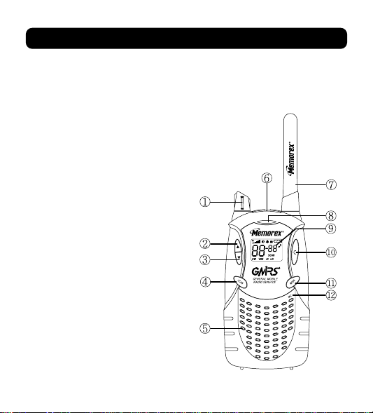
Controls and Indicators
1. Power On / Off and Volume Control
2. Up Channel
3. Down Channel
4. SCAN / Lock Button
5. Built-In Speaker
6. External Speaker Jack and Mic Jack
(under rubber flap)
7. Antenna
8. Transmit /
Receive LED Indicator
9. LCD Screen
10. CALL Button
11. MODE Button
12. Built-In Microphone
Page 7
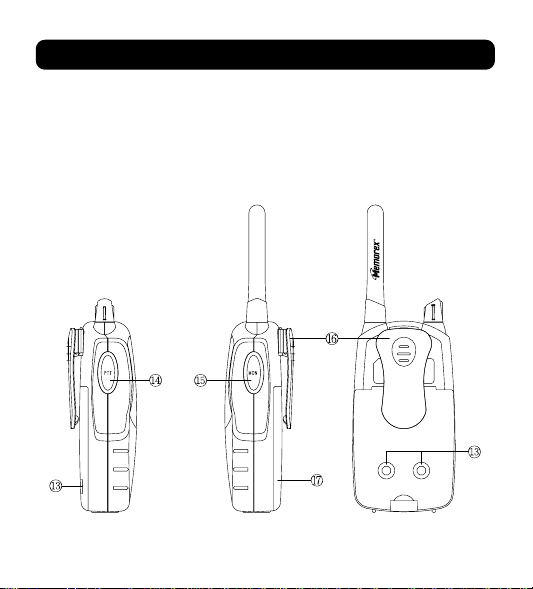
Controls and Indicators
4
13. Charging Terminals
14. Push-to-Talk (PTT) Button
15. MONITOR/Backlighting Button
16. Detachable Belt Clip
17. Battery Door
Page 8
5
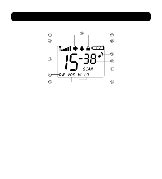
LCD Display Indicators
1. Monitor Indicator
2. Signal Strength Indicator
3. Main Channel Indicator
4. Dual Watch Mode Indicator
5. VOX Indicator
6. Roger Beep Indicator
7. Key Lock Indicator
8. Battery Level Indicator
9. Beep Tone Indicator
10.
CTCSS Sub-Channel Indicator
11. Scan Indicator
12. TX Power Hi/Low Indicator
Note : The Battery icon at the top right of the display will indicate the
battery power left in the installed batteries, or rechargeable
battery pack. Replace the batteries, or charge the rechargeable battery pack when the Battery icon blinks.
Page 9
Operation
6
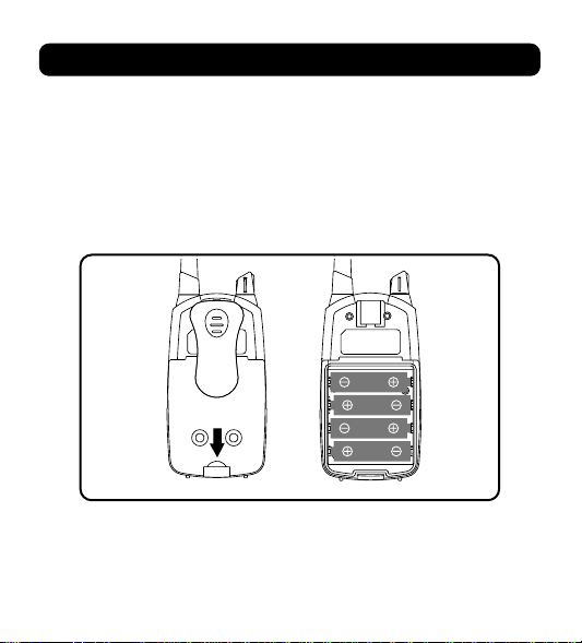
Installing The Batteries
Remove the Battery Clip(if installed).
1. Pull locking tab located at the bottom of the battery compartment
down and lift the door up to remove the battery cover.
2. Insert four “AA” size batteries (or Rechargeable Battery Pack)
Position batteries according to polarity markings.
Page 10
Operation
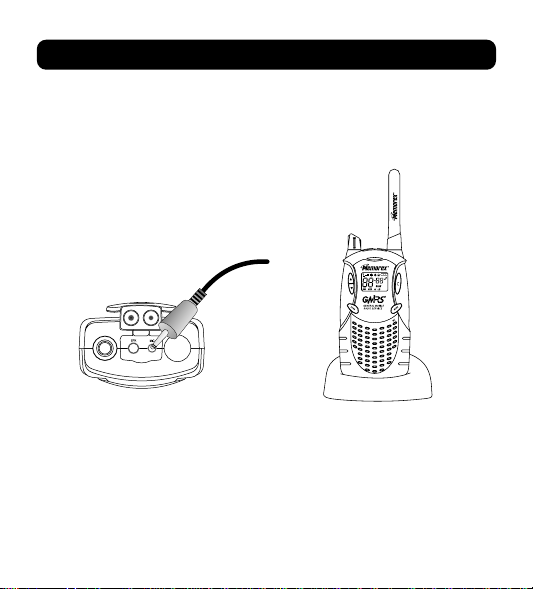
Recharging The Batteries
You can charge your GMRS radio by using an AC/DC wall adaptor
or a desktop adaptor. Both chargers are not included, but can be
purchased separately.
Note : Do not charge unit using an AC/DC adapter with regular
AA ALKALINE BATTERIES installed. Only use the AC/DC
adaptor with AA NI-MH RECHARGEABLE BATTERIES.
(Charger and rechargeable batteries not included.)
Plug in the AC/DC Wall
charger as shown
7
Place the radio into the
cradle as shown
Page 11
Operation
8
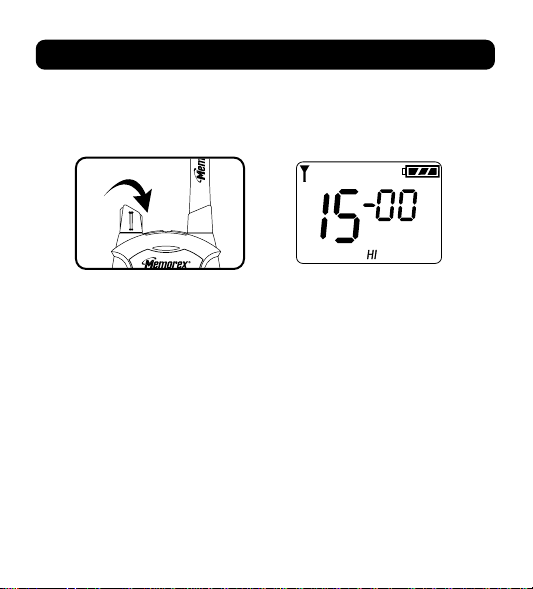
Turning On Your Unit
Rotate On/Off Volume control knob “clockwise”. An audible tone will
indicate the unit is on and then the LCD will go to operation mode.
Note : Whenever the unit is on, you can receive communications.
Adjusting The Volume
Rotate the Power On/Off Volume control knob “clockwise” or
“counter clockwise” to adjust the volume level.
Talking To Another Party
To send your outgoing message and to communicate with another
party,
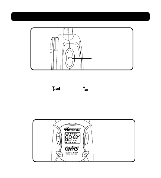
1. Press and hold the PTT button to transmit your message.
2. Release the PTT button to hear the person you are talking to.
3.
While the PTT button is depressed, you can not receive incoming calls.
Page 12
9
Operation
Note : When you press and hold the PTT button, the signal
strength indicator will be displayed to confirm TX signal
strength Hi ( ) or Low ( ).
Mode Button
This button is used to select various feature settings in your MK
1995 GMRS Radio.
Mode
button
Push to talk
Page 13
Operation
10
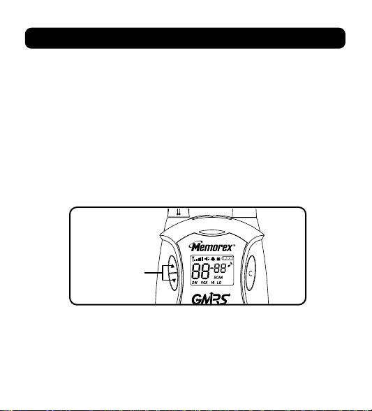
Note : After the MODE button is pressed, the Up(▲) or Down(▼)
button must be pressed within 8 seconds, otherwise, the unit
will revert back to Normal mode.
Selecting Main Channels (1-15)
Your MK1995 GMRS Radio has 15 main channels.
To select the channel,
Press the Up(▲) or Down(▼) button to select the desired channel.
Push to
select
channel
Page 14

11
Operation
Selecting Tone Code (CTCSS Sub-Channel)
This feature allows you to utilize the coded squelch tones (00~38)
within one of the 15 main channels. This enables you to communicate
with another party on the same main channel using the same subchannel and filters out unwanted transmissions without the same
coded tone code.
To Select the CTCSS Sub-Channels,
1. While in the normal mode (not scan mode), press the MODE
button once.
2. A flashing sub-channel number will be displayed on the LCD screen.
3. Press the Up(▲) or Down(▼) button to select the desired
sub-channel.
4. Press the MODE button 7 times, or simply press the PTT button
once to set the channel, and exit from the CTCSS selecting mode.
Mode
button
Flashing
Page 15

Operation
12
Transmit Power Hi/Low
Your MK1995 Radio permits selection of the transmitting power level
to High (2W) or Low (0.5W).
1. Press the MODE button twice and the Power ( ) icon and level
will appear on the LCD screen.
2. Select Hi or Low by pressing the Up(▲) or Down(▼) button.
3. To exit from the Transmit power selection mode by pressing the
MODE button 6 times, or simply pressing the PTT button.
Flashing
Page 16

13
Operation
Dual Watch Mode
This feature allows you to monitor two channels at the same time.
While in dual watch mode, the unit will continuously monitor both the
primary and dual watch channel. Received signals will be heard for 5
seconds, then the unit will resume scanning the two channels.
Pressing the PTT button during a received transmission will set the
unit to transmit on the same channel. Pressing the PTT button when
no signal is received will set the unit to transmit on the primary channel.
To set the Dual Watch Mode,
1. Press the MODE button 3 times until the ( ) icon is flashing.
2. Select the desired channel by pressing the Up(▲) or Down(▼) button.
3. Press the PTT button or the MODE button 5 times to exit from the
selecting mode.
4. Press the SCAN button momentarily to cancel the dual watch
mode.
Flashing
Page 17

Operation
14
VOX Mode
This feature enables you to have hands-free conversation. Your
voice or nearby sound is detected and the radio transmits without
the need to press the PTT button.
To set the radio for VOX operation,
1. Press the MODE button 4 times, and the ( ) icon will appear
and flashing on the LCD screen.
2. Press the Up(▲) or Down(▼) button to select VOX off and from 1
to 3 VOX level sensitivity. The higher the number, the higher the
sensitivity.
3. To exit from the VOX selection mode by pressing the MODE button 4
times, or simply pressing the PTT button.
4. Vox can be turned off by selecting “ ” as the setting.
Note : The VOX icon will be displayed on the LCD screen after setting
.
When you are in VOX operation, Roger Beep will be disabled.
Flashing
Page 18
15
Operation
Key Tone Setting
This feature allows the radio to sound a confirmation beep tone
whenever keys are pressed.
To turn the key tones on or off,
1. Press the MODE button 5 times until the ( ) icon is flashing on
the LCD screen.
2. Press the Up(▲) or Down(▼) button to enable (“ ” will appear
on the LCD) or disable (“ ” will appear on the LCD screen) the
key tone feature.
3. To exit from the selecting mode, press MODE button 4 times, or
simply press the PTT button once.
Note : When the key tone is on, the ( ) icon will be displayed
on LCD screen.
Flashing
Page 19

Operation
16
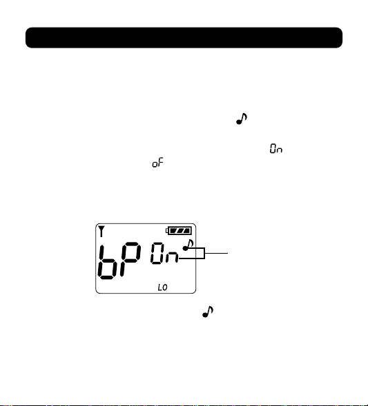
Roger Beep Tone
The Roger Beep is a tone which is automatically transmitted whenever
the PTT button is released.
To enable or disable the Roger Beep Tone,
1. Press the MODE button 6 times until the ( ) icon is flashing on
the LCD screen.
2. Press the Up(▲) or Down(▼) button to enable (“ ” will appear on
the LCD) or disable (“ ” will appear on the LCD) the Roger Beep
Tone feature. When enabled, the ( ) icon will appear on the LCD
screen.
3. To exit from the Roger Beep Tone feature, press the MODE
button 2 times, or simply press the PTT button.
Flashing
Page 20

17
Operation
Selecting Call Tones
Your MK1995 GMRS radio provides 3 user selectable call tones to
alert you of an incoming signal.
To select your favorite call tones,
1. Press the MODE button 7 times and “ ” will appear on the LCD
screen.
2. Push the Up(▲) or Down(▼) button to select your favorite call
tone.
3. Press the MODE button once to exit from the Call Tone selection
mode, or simply press the PTT button once.
Flashing
Page 21

Operation
18
Main Channel Scan
This feature allows you to monitor all channels automatically for valid
signals. While scanning, you can transmit and receive. When a signal
is received, scan is interrupted and you will hear the channal for 5
seconds. After the 5 seconds, the unit will resume scanning unless
the Scan button is pressed again as described below.
1. To start Scan mode, press the SCAN button momentarily.
The ( ) icon will be displayed on the LCD screen and the unit
will scan through the 15 channels to find an active channel. When
an active channel is found, it will be heard for 5 seconds, and then
scanning will resume.
2. If the unit does not locate an active signal and you would like to
transmit, press the PTT button to return to home channel operation.
After approximately 5 seconds after the communication is completed, the transceiver will automatically resume scanning.
3. To exit from the Scan mode, press the SCAN button again. The unit
will return to normal operation and the ( ) icon will disappear
from the LCD screen.
Page 22

19
Operation
CTCSS Sub-Channel Scan
This feature will scan all CTCSS sub-channels. It will pause to hear
any active transmissions for 5 seconds, and will resume scanning in
order.
To activate the CTCSS scan mode,
1. Press the MODE button once to select the CTCSS function.
The sub-channel digits will blink in the LCD screen.
2. Press the SCAN button. The radio will start scanning for all
sub-channels (01~38).
3. To disable the Sub-Channel scan, press the SCAN button
again. The radio will return to normal operation, and the last
sub-channel will be memorized.
Key Lock
This feature prevents accidental channel change to the preferred
settings of the unit. The Key Lock function will temporarily disable
the Channel Up/Down, Scan, and Mode button.
To activate Key Lock :
1. Press and hold the SCAN button for 2 seconds. The key Lock
icon ( ) will appear on the LCD screen and the Key Lock
function will be activated.
Page 23

Operation
20
2. To unlock the Key Lock function, press and hold the SCAN button
for 2 seconds. The ( ) icon will disappear and normal operation
will resume.
Calling Another Party
To alert another party that you wish to communicate with,
1. Select a desired channel by pressing the Up(▲) or Down(▼)
button.
2. Press the Call(C) button.
3. Wait for the party's response or proceed to talking with the other
party.
Note : Both the calling and receiving units must be on the same
main channel and sub-channel for the call function to work.
When Call(C) button is pressed, Signal Strength indicator
and TX/RX LED indicator will turn on.
Press for
2 seconds
Key Lock
icon
Page 24

21
Operation
Monitor
Your MK 1995 radio has the feature to check for weak signals in the
current channel.
1. Press and hold the Monitor (MON) button for 2 seconds until the
Monitor( ) icon appears on the LCD screen and the signal is
heard.
2. To return to normal operation, press and hold the Monitor (MON)
button for 2 seconds again.
Press for
2 seconds
for Monitor
function
Monitor icon
Call
RED
Page 25

Operation
22
LCD Back-Lighting Lamp
This lamp is used to illuminate the LCD screen. It turns on every
time you press and release the monitor (MON)button momentarily.
The lamp will go out after 4 seconds.
TX / RX Indicator LED Lamp
When the PTT button is pressed, the red (TX) LED will light to
confirm transmitting signal. When you are receiving signals from
another party, the green (RX) LED will light.
Auto Power Saver
Your MK1995 unit has a unique circuit designed to extend battery
life. If there are no transmissions within 5 seconds, the unit will
automatically switch to Battery Save Mode.
TX/RX LED
indicator
Page 26

23
Operation
Note : The Auto Battery Save Circuit does not effect the unit's
ability to receive incoming transmissions.
Low Battery Indicator
When the batteries are low and need re-charging, the ( ) icon
will be blinking and audible beep tones will sound.
If using standard batteries, replace them. If using rechargeable
batteries, recharge them.
Low Battery
indicator
Page 27

External Microphone/Speaker
24
External Microphone Jack
Your MK1995 has an external microphone jack which enables you
to connect an external microphone in order to free your hands for
other tasks.
Simply raise the rubber flap and insert the microphone plug into the
microphone jack on the top of the unit.
Note : External speaker and microphone are not included with this
standard package.
Page 28

Notes for Better Communication
25
1. Your MK1995 GMRS radio has been designed to maximize
performance and improve transmission range in the field. To
avoid interference, it is recommended that you do not use the
unit closer than 5 feet from another unit.
2. For better transmission results, keep your mouth about 2-3
inches from the microphone and speak slowly in a normal
voice.
3. Reverse polarity( + / - ) may cause serious damage to the unit.
Make sure not to reverse the polarity( + / - ) of the batteries in the
battery compartment.
Page 29

OperationSpecial Warning
26
1. Do not operate the transceiver unless you are licensed to do so.
2. Avoid exposing the transceiver to water or extreme temperatures.
3. Do not attempt to modify or in any way increase the output of
this transceiver. Its output is designed to meet the legal limits
set by the FCC.
4. Do not use this device or change its batteries in potentially
explosive atmospheres as sparks in such areas could result in
an explosion.
5. Turn your transceiver off wherever posted notices restrict the
use of radios or cellular phones. Facilities such as hospitals may
use equipment that is sensitive to RF energy.
Page 30

Note : See end of the manual for our web page and toll-free number
is you need additional assistance.
27
Troubleshooting Guide
Problem Possible Cause Correction
No transmission while
pressing the PTT button.
Unit is on, but will not be
operated.
Weak or no signal
received.
Weak batteries. Charge or replace batteries.
Unit beeps, but will
not function when
turned on.
Batteries extremely
discharged.
Charge or replace batteries.
Reception of
unwanted signals
CTCSS not on. Turn on CTCSS sub-tone code.
Channel or Tone Code
not set the same as target
transceiver.
Adjust the unit's setting to
match those settings of the
target transceiver.
Volume level too low.
PTT key inadvertently
depressed.
Increase volume level.
Release PTT button.
Excessive radio
interference.
Change to a different channel.
Weak batteries.
Incorrect battery
polarity.
Charge or replace batteries.
Install the batteries following the
polarity diagram inside the
battery compartment.
Page 31

Special Note
28
If the batteries are not installed properly, the following can occur.
In this case, change the batteries:
1. Same symptom as Low battery.
2. Green LED will light.
3. Cause damage to the unit.
Page 32

29
Specifications
1. General Specifications
Frequency Range (15CH GMRS) 462.5500 - 462.7250
Channel Spacing 12.5KHz
Sub-Tone Code(CTCSS) 38 for each main channel
Dimension w/o Antenna
127mm(H) x 61mm(W) x 34mm(D)
Standard Batteries
Alkaline 2400mA AA(4), 6VDC
Rechargeable Batteries
Ni-MH 1200mA AA(4), 4.8VDC
Operation Time (5-5-90) 37 hours at Hi power
57 hours at Low power
2. Receiver
Useable Sensitivity > -119 dBm
Maximum Audio Output Power > 0.3 Watt Max (8 Ohm)
Modulation Distortion < 5%(1 KHz 70%)
3. Transceiver
RF Output Power
1.8W Max(at Hi)/0.5W Max(at Low)
Max Deviation +/- 2.5 KHz
Modulation Distortion < 5%(1 KHz 70%)
Page 33

GMRS Channel Frequencies
30
Main Channel Frequencies
1
2
3
4
5
6
7
8
9
10
11
12
13
14
15
462.5625
462.5875
462.6125
462.6375
462.6625
462.6875
462.7125
462.5750
462.6250
462.6750
462.5500
462.6000
462.6500
462.7000
462.7250
Channel Frequencies(MHz)
Page 34

GMRS Channel Frequencies
31
CTCSS(Continuous Tone Code Squelch System) Tone Frequencies(in Hz)
CTCSS Freq. Hz
1
2
3
4
5
6
7
8
9
10
11
12
13
14
15
16
17
18
19
67.0
71.9
74.4
77.0
79.7
82.5
85.4
88.5
91.5
94.8
97.4
100.0
103.5
107.2
110.9
114.8
118.8
123.0
127.3
CTCSS Freq. Hz
20
21
22
23
24
25
26
27
28
29
30
31
32
33
34
35
36
37
38
131.8
136.5
141.3
146.2
151.4
156.7
162.2
167.9
173.8
179.9
186.2
192.8
203.5
210.7
218.1
225.7
233.6
241.8
250.3
Page 35

FOR ADDITIONAL SET-UP OR OPERATING ASSISTANCE, PLEASE VISIT OUR WEBSITE AT
WWW.MEMCORPINC.COM OR CONTACT CUSTOMER SERVICE AT 1-800-919-3647
PLEASE KEEP ALL PACKAGING MATERIAL FOR AT LEAST 90 DAYS IN CASE YOU NEED TO
RETURN THIS PRODUCT TO YOUR PLACE OF PURCHASE OR MEMOREX. FOR PARTS AND
ACCESSORIES, CONTACT FOX INT’L AT 1-800-321-6993.
Page 36

M e m o
Page 37

M e m o
Page 38

Memcorp Inc
Weston, FL 33331
Printed in Korea
Visit our website at www.memcorpinc.com
 Loading...