

Page 1
Vacuum oven with Peltier cooling
VO COOL 200
VO COOL 400
Pump Module
PM 200
PM 400
OPERATING INSTRUCTIONS
Page 2

VO Cool
...........................................................................................................................................................
....................................................................................................................................................
..............................................................................................................................................................
...........................................................................................................................................
............................................................................................................................
..................................................
....................................................................................................................................................
.............................................................................................................................................
.......................................................................................................................
...............................................................................................................................................
............................................................................................................................................
..........................................................................................................................
............................................................................................................
............................................................................................................
..............................................................................................................
PRINT
SETUP
..............................................................................................................
MAX
MIN
..............................................................................................................
AUTO
.............................................................................................
.................................................................................................................................................................
...................................................................................................................................
..........................................................................................................................
...........................................................................................................................
..................................................................................................................................................................................
............................................................................................................................
Page 3

VO Cool
page 3
..............................................................................................................................................................
..............................................................................................
............................................................................................................
.............................................................................
............................................................
....................................................................................................................
....................................................................................................................................................................
..............................................................................................................................................................
..............................................................................................
...........................................................................................................................................................
.............................................................................................................................................................
.........................................................................................................................................
.........................................................................................................................................................................
Page 4
VO Cool
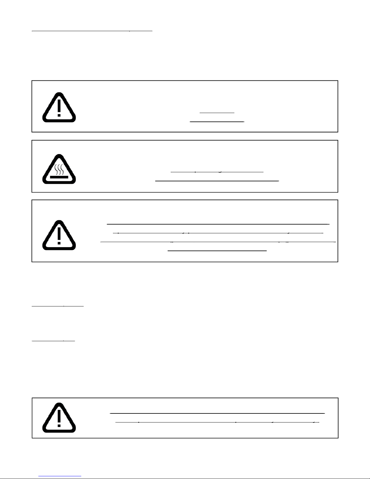
This mark in the Operating Instructions means:
Watch out
You have purchased a technically fully proven product which has been produced in Germany with the use
This mark on the product means:
Warning – oven hot when operating!
Warning – oven hot when operating!
The right to technical modifications is reserved.
The door and the security glass panels must be checked regularly for scratches or damage. No vacuum
Always use gloves!
Page 5
VO Cool
page 5
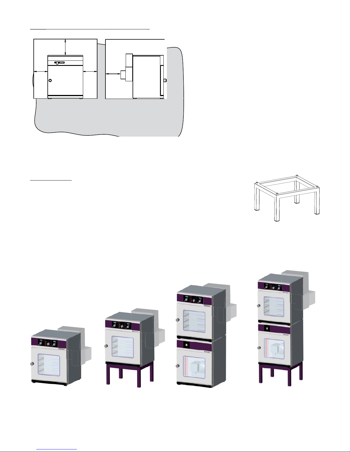
min. 15
cm
min. 8
cm
min. 8
cm
min. 20
cm
The oven can be placed on the floor or on a
(see Section:
„Maintenance“)
The spacing from the back of the oven to the
Page 6

VO Cool
When the oven is started up for the first time, it should be supervised continuously until steady conditions
Page 7

VO Cool
page 7
Width G [mm]
Weight [kg]
Vacuum oven
Ambient conditions
Ambient temperature 5°C to 40°C
Working temperature range
mbar 1/sec
Page 8

VO Cool
Alphanumeric text display
Vacuum pressure control for digital operation of the built-in solenoid valves
Visual alarm indication
Temperature-dependent control unit ventilation
A pre-formatted blank MEMoryCard XL with 32 kByte storage capacity, reprogrammable for up to 40
Page 9

VO Cool
page 9
WARNING! Always pull out the supply plug before
WARNING! Always pull out the supply plug before
When connecting a MEMMERT oven to the electrical supply you have to observe any local
regulations which apply (e.g. in Germany DIN VDE 0100 with FI protection circuit)
This product is intended to operate on a supply network with a system impedance Zmax at the
transfer point (building connection) of 0.292 Ohm max. The user has to ensure that the product is
only operated on an electrical supply network which meets these requirements. If necessary, details
of the system impedance can be obtained from the local electricity supply authority.
Any work involving opening up the oven must only be carried out by a suitably qualified
Any work involving opening up the oven must only be carried out by a suitably qualified
Working space: stainless steel (Mat.Ref. 1.4404) featuring high stability, optimal hygienic properties,
and corrosion resistance against many (not all!) chemical compounds (warning against chlorine
compounds, for example).
The load for the vacuum drying oven must be carefully evaluated for its chemical compatibility with the
A table listing about the compatibility of all these materials can be requested from MEMMERT.
Page 10
VO Cool
Page 11
VO Cool
page 11
Vacuum pump (optional)
Page 12

VO Cool
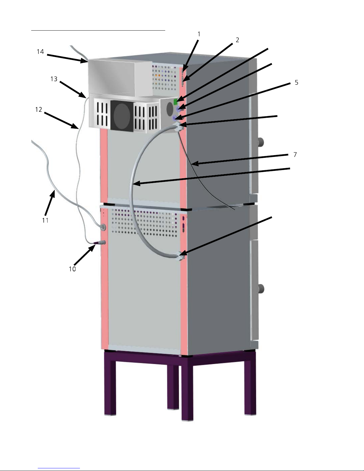
a suitable external vacuum pump, using the Neoprene connection tubing (8) supplied with the
pump module.
together using the cable (12) supplied with the equipment.
to the gas inlet IN2 (4). The maximum pressure of 1.5 bar must not be exceeded! (Use pressure
reducing valve for 1.5 bar max.)
Turn on the CDP Peltier cooling unit (3)
Warning
Warning
Page 13

VO Cool
2
1
3
page 13
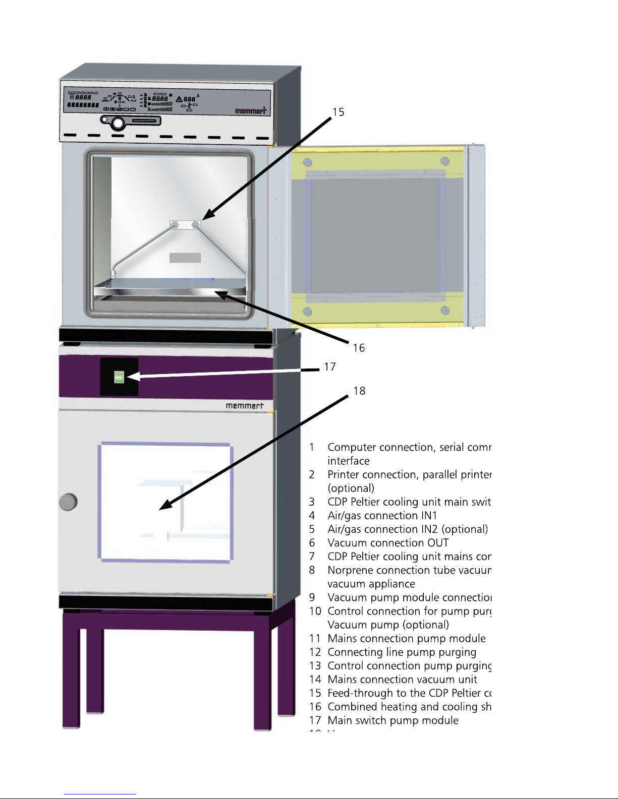
7 Switching output for external vacuum pump
purge valve and pump control (option)
The 3-way switched output serves to control the vacuum
pump of the optional pump module (PM) of the vacuum oven
(VO).
7.1 Vacuum pump purge valve
When loads with a high moisture content are being dried
there is a possibility during prolonged operation that the
pump output decreases through condensate forming in the
pump heads. The diaphragms can be blown free by briefly
purging the pump heads with fresh air. This improves the
effectiveness of the drying process.
Note:
In conjunction with the optionally available pump modules
PM 200, PM 400 and PM 500 this cyclic purge takes place
automatically as the pump performance deteriorates.
Decisive advantage:
The drying process takes place more rapidly and with reduced
energy consumption, the wear on the pump is reduced.
This function can be de-activated by removing the pump purge connecting cable at the back of the unit.
7.2 Demand-controlled vacuum pump shut-down (option)
After the end of a drying programme, or after prolonged operation with any vacuum demanded by the
controller, the vacuum pump incorporated in the pump module (PM) is switched off via the control line.
Note:
A control signal switches off the vacuum pump incorporated in the optional pump module (PM). The
signal lamp in the main switch of the pump module remains alight even when the vacuum pump has been
switched off via the control line.
Decisive advantage:
The demand-controlled shut down of the vacuum pump reduces energy consumption and increases the
life of the vacuum pump by reducing the wear on the pump diaphragms.
This function can be de-activated by removing the pump purge connecting cable at the back of the unit.
The vacuum pump is then running continuously.
Pin connections of the socket
on the back of the unit:
1 output purge valve
GND (switched)
2 24V DC
3 pump switch-off
GND (switched)
Page 14

VO Cool
The load must only be placed on the thermoshelves.
combination with air.
on the tray.
When the oven is being operated with inert gas (nitrogen, helium, neon, argon, krypton) there is a small
The list of MAK values (maximum workplace concentration) and of BAT values (biological workplace
The appropriate specifications of the trade association publication „Guidelines for the Laboratory“ (ZH1/119)
Avoid any open fire in the area near the gas cylinders. Inert gas is not combustible, but it is
possible for the cylinder to burst.
flow into the cylinder.
When not in use, close the shut-off valve.
The instructions and safety information of the gas supplier have to be observed.
Page 15

VO Cool
page 15
(with venting cycles).
cycles should be chosen to suit the moisture content of the load.
during evaporation may result in the set temperature not being reached.
The oven described in these Operating Instructions
The oven described in these Operating Instructions
The ovens described here must never be operated
The ovens described here must never be operated
Page 16
VO Cool
set
off
on
push
card
PRINT
SETUP
loop
t3
t4
t2
t1
on
off
Mo
Tu
We
Th
Fr
Sa Su
STERI DEFRO
°C
°C
rh
%
2
IN 1
IN 2
OUT
IN 1
IN 2
OUT
MIN
AUTO
MAX
mb
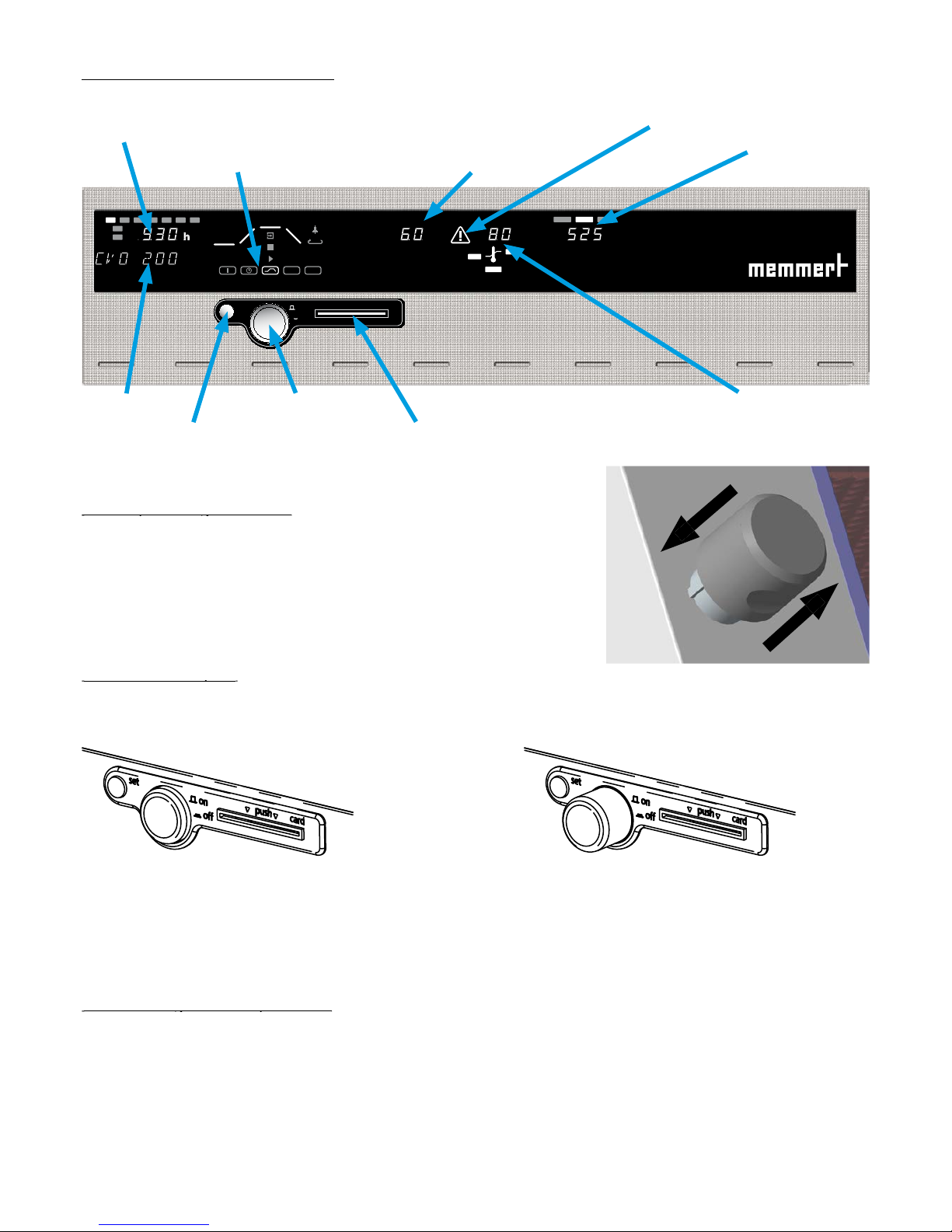
The oven is switched on by pressing the push/turn control.
After the SET key has been released the display briefly flashes the temperature setpoint. The display then
open
close
The door is opened by pulling on the door handle.
The door is closed by the door handle being pushed in.
(main switch)
open
close
Page 17

VO Cool
page 17
The quick venting function is used in unloading and loading the vacuum oven without having to alter the
in the menu.
again.
Page 18

VO Cool
PRINT
SETUP
After holding down the SET key (approx. 3 sec), the current operating mode flashes on the display. A
After the SET key has been released the controller operates in the new operating mode.
After an operating mode has been selected, all relevant controller settings are shown simultaneously on
A parameter (menu item) can be selected by rotating the push/turn control; all other parameters are then
The selected parameter flashes brightly and can now be altered with the push/turn control while holding
After the SET key has been released the newly set value is stored.
Weekly
Weekly
operation
operation
Page 19

VO Cool
page 19
18 Normal operation
PRINT
SETUP
In this operating mode the oven operates continuously. The settings for operating the oven can be selected.
The settings act directly on the operation of the oven.
STERI DEFRO
°C
°C
rh
%
IN 1
IN 2
OUT
IN 1
I
MIN
AUTO
MAX
mb
By rotating the push/turn control the following parameters can be selected and can be altered as described
in the Section „Setting the parameters“:
Temperature setpoint
Range: 5°C to 90°C
Optionally -5°C to 90°C
Note: If operating temperatures below
room temperature are not required: Turn
off the CDP Peltier cooling unit.
°C
Temperature monitor
Adjustment range: MIN MAX AUTO
(see Section: “Temperature monitor“)
MIN
MAX
AUTO
°C
Pressure setpoint
Range:
5mb to 1100mb
LO = valve OUT permanently open
mB
Page 20

VO Cool
The unit should cool down to 6° C and be evacuated to 500 mb. The monitoring function should respond
Temperature
Pressure
mb
Time
Time
20 °C
0 °C
5 °C
After holding down the SET key (approx. 3 sec), the current operating
After the SET key has been released the controller is in
PRINT
SETUP
After the SET key has been released the oven briefly flashes the
The display then changes to the actual temperatureand the controller
°C
Turn the push/turn control clockwise until the overtemperature display
MAX
10°C
MIN
AUTO
MAX
C
After releasing the SET key the oven briefly flashes the vacuum setpoint.
The display then shows the actual pressure and the control starts to
mB
Page 21

VO Cool
page 21
PRINT
SETUP
While the weekly programmer is in the OFF phase the oven is in standby mode. Heating and fan are
The sequence of the weekly programmer is repeated every week.
A maximum of 9 time blocks, each consisting of ON time and OFF time, can be programmed.
Mo
Tu
We
Th
Fr
Sa
Su
h
o
o
Section “Setting the parameters“
Weekday
Weekday
Mo
Tu
We
Th
Fr
Sa
Su
weekend Sa-Su
Mo
Tu
We
Th
Fr
Sa
Su
Mo
Tu
We
Th
Fr
Sa
Su
----
on
off
to
hrs.
on
off
h
on
off
h
When the controller is in stand-by mode or if the weekly programmer is in the ON phase, the temperature
Page 22

VO Cool
The oven (VO500) has to switch on at 07.30 hrs from Mo to Fr (workday group) and switch off at 18.00
Mo
Sa
Fr
Th
We
Tu
Su
After holding down the SET key (approx. 3 sec) the current operating
After the SET key has been released the controller is in operating mode
PRINT
SETUP
Turn the push/turn control anticlockwise to select the symbols “Mo-Fr
7:30
Sa
Su
off
Mo
Tu
We
Th
Fr
h
on
18:00
Sa
Su
on
Mo
Tu
We
Th
Fr
h
off
10:00
Mo
Tu
We
Th
Fr
Su
off
Sa
h
on
14:00
Mo
Tu
We
Th
Fr
Su
on
Sa
h
off
Page 23

VO Cool
page 23
PRINT
SETUP
an existing programme can be edited
After EDIT
has been activated, the following parameters can be selected and can be altered as
Section “Selecting the parameters“:
PRINT
SETUP
loop
t3
t4
t2
t1
on
off
Mo
Tu
We
Th
Fr
Sa Su
°C
MAX
°C
h
PRINT
SETUP
loop
t3
t4
t2
t1
on
off
Mo
Tu
We
Th
Fr
Sa Su
°C
MAX
°C
h
to
Page 24

VO Cool
PRINT
SETUP
loop
t3
t4
t2
t1
on
off
Mo
Tu
We
Th
Fr
Sa Su
MAX
°C
h
rh
IN1
IN2
U T
1
minute to
hours
PRINT
SETUP
loop
t3
t4
t2
t1
on
off
Mo
Tu
We
Th
Fr
Sa Su
MAX
h
°C
mb
IN 1
IN 2
OUT
PRINT
SETUP
loop
t3
t4
t2
t1
on
off
Mo
Tu
We
Th
Fr
Sa Su
MAX
h
°C
mb
IN 1
IN 2
OUT
Vacuum at the end of the ramp segment
Vacuum at the end of the ramp segment
Adjustment range:
10
1100
mbar or
PRINT
SETUP
loop
t3
t4
t2
t1
on
off
Mo
Tu
We
Th
Fr
Sa Su
MAX
h
°C
mb
IN 1
IN 2
OUT
(see Section: „Closure commands for ramp segments“)
PRINT
SETUP
loop
t3
t4
t2
t1
on
off
Mo
Tu
We
Th
Fr
Sa Su
MAX
h
°C
mb
IN 1
IN 2
OUT
Turn the push/turn control clockwise unti
appears on the display, briefly press the SET key to enter
Page 25

VO Cool
page 25
Wait until the setpoint temperature is reached.
The oven only starts the next programme segment when the programmed
Wait until the set vacuum has been reached.
The oven starts the next programme segment only when the programmed
Wait until temperature setpoint and vacuum setpoint have been
The oven starts the next programme segment only when the programmed
the programmed vacuum have been reached,
The set programme is repeated after passing through all programmed
1-99
= repeats
= continuous repeat function
The programme segments are linked together by the segment closure command. These commands
°C
Ramp
closure
command
ramp
segment 1
spwt (t)
segment 1
closure
command
ramp
segment 2
next
closure
command
ramp
segment 4
next
closure
command
ramp
segment 5
end
closure
command
ramp
segment 3
spwt (t)
segment 3
segment 1
segment 5
segment 4
delayed
programme start
Page 26

VO Cool
The oven has to heat up on Monday at 8.00 hrs, and after reaching the temperature be evacuated to 50
After holding down the SET key (approx. 3 sec) the current operating
After the SET key has been released the controller is in operating mode
PRINT
SETUP
After the SET key has been released, the controller is in the programme
Mo
Tu
We
Th
Fr
Sa
Su
using the push/turn
h
Turn the push/turn control further clockwise until the time of the first
using the push/turn
h
Turn the push/turn control clockwise until the temperature display is
using the push/turn control.
°C
1050
mB
Page 27

VO Cool
page 27
Turn the push/turn control to the right until the INLET display flashes.
Turn the push/turn control clockwise until a segment closure command
) appears.
using the push/turn
h
Turn the push/turn control clockwise until the temperature display is
using the push/turn control.
°C
mB
Turn the push/turn control to the right until the INLET display flashes.
Turn the push/turn control clockwise until a segment closure command
) appears.
with the push/turn control.
using the push/turn
h
Turn the push/turn control clockwise until the temperature display is
using the push/turn control.
°C
mB
Page 28

VO Cool
Turn the push/turn control to the right until the INLET display flashes.
Turn the push/turn control clockwise until a segment closure command
) appears.
with the push/turn control.
using the push/turn
h
Turn the push/turn control clockwise until the temperature display is
using the push/turn control.
°C
1050
mB
Turn the push/turn control to the right until the INLET display flashes.
Turn the push/turn control clockwise until a segment closure command
) appears.
with the push/turn control.
Turn the push/turn control clockwise until
appears on the display.
Turn the push/turn control clockwise and set the temperature monitor.
(see Section: “Temperature monitor”)
MIN
AUTO
MAX
˚C
Turn the push/turn control anticlockwise until the stop symbol
is
with the push/turn control.
Page 29

VO Cool
page 29
PRINT
PRINT
SETUP
VO ovens may be equipped with a parallel printer interface, as used in personal computers.
This parallel printer interface on the back of the oven is suitable for connecting conventional PCL3-
The controller is provided with an internal log memory
(see Section: „Log memory”).
The report data can
When using a colour printer, the various graphics can be printed in colour.
Section Setting the parameters.
Page 30

VO Cool
SETUP
PRINT
SETUP
The following parameters can be selected by turning the push/turn control, and altered as described in the
Section „Setting the parameters“
The winter/summer time changeover does not take place automatically
h
The controller incorporates a calendar which automatically allows for
Weekday
Weekday
Mo
Tu
We
Th
Fr
Sa
Su
Year
to
Audible signal at programme end
Audible signal at programme end
or
Audible signal on alarm, e.g. overtemperature
Audible signal on alarm, e.g. overtemperature
OFF
or
to 15
(see Section: „Communication interface”)
Tolerance margin ASF
Tolerance margin ASF
to
(see Section: „Temperature monitor”)
Page 31

VO Cool
page 31
GERMAN, English, franCEAIS, ESPANOL
Vent connection select IN1 or IN2 (option)
Vent connection select IN1 or IN2 (option)
or
to
(see Section: „Calibration“)
to
(see Section „Calibration“)
The real-time clock is set in SETUP and includes date and clock time.
The real-time clock serves for documentation according to GLP.
The clock runs with a buffer battery independently of the mains power supply.
The built-in lithium battery Type CR 2032 has a life of approx. 10 years.
Page 32

VO Cool
The monitoring temperature is measured in the combined heating and cooling sheet by a PT100 temperature
The oven is provided with duplicate overtemperature protection (mechanical / electronic) according to DIN 12 880.
MIN
MAX
AUTO
°C
All ovens of the VO series are equipped with a mechanical temperature limiter (TB)
up as warning
The oven is again ready for operation only after it has cooled down and after the fault has been
(TWW, TWB)
Audible
Automatic
TWB-alarm
ASF-alarm
Page 33

VO Cool
page 33
MAX
MIN
MAX
AUTO
˚C
MAX
MIN
The low alarm cannot be programmed
Where no undertemperature protection is
MIN
MAX
AUTO
°C
MIN
The temperature monitor can be set independently of the operating mode.
Page 34

VO Cool
The manually set monitor temperature and the electronic overtemperature protection are monitored on
VO-ovens by an adjustable temperature monitor (TWW) Protection Class 3.1 to DIN 12 880:
MAX
is exceeded, the TWW takes over the control of the
is
TB approx. 20°C above Tmax
TWW set manually
setpoint temperature
t
°C
controller fault
emergency operation
Page 35

VO Cool
page 35
AUTO
A monitoring device which automatically follows the selected temperature setpoint.
The tolerance margin of the ASF is set in SETUP
(see the menu item Tolerance margin ASF in the Section
„Basic oven settings SETUP“).
Automatic temperature
MIN
MAX
AUTO
°C
using
Automatic temperature
MIN
MAX
AUTO
°C
using
The tolerance margin for the ASF is selected in SETUP
(see the menu item Tolerance margin ASF in the
Section „Basic oven settings SETUP”).
Tolerance margin reached = ASF activated
Tolerance margin reached = ASF activated
The ASF is automatically activated when the actual temperature has reached 50% of the selected tolerance
The activation of the automatic temperature monitor is indicated by the bright
AUTO
70°C
50°C
ASF Alarm
ASF active
ASF activated
70°C
50°C
ASF activated ASF activated
40°C
20°C
0°C
20°C
40°C
60°C
80°C
ASF set to
Page 36

VO Cool
Triggering the ASF alarm is indicated by flashing
AUTO
and
-symbol.
70°C
50°C
ASF Alarm
ASF active
ASF activated
70°C
50°C
ASF activated ASF activated
40°C
20°C
0°C
20°C
40°C
60°C
80°C
Again within tolerance margin = ASF alarm switched off
Again within tolerance margin = ASF alarm switched off
The automatic temperature monitor alarm is switched off automatically as soon as the selected tolerance
70°C
50°C
ASF Alarm
ASF active
ASF activated
70°C
50°C
ASF activated
ASF activated
40°C
20°C
0°C
20°C
40°C
60°C
80°C
ASF set to
ASF set to
Page 37

VO Cool
page 37
70°C
50°C
ASF Alarm
ASF active
ASF activated
70°C
50°C
ASF activated ASF activated
40°C
20°C
0°C
20°C
40°C
60°C
80°C
ASF set to
Page 38

VO Cool
correction to 0.0°C.
reference instrument.
calibration correction setting has to have a negative sign.
to 40.0°C in SETUP and set the corresponding calibration
correction to 0.0°C.
operation for a setpoint temperature of 40°C.
to –0.4°C.
a further calibration temperature can be programmed below
, and with
an
additional calibration temperature above
CAL 1
+0,5°C
CAL 3
+0,8°C
CAL 2
-0,4°C
Factory calibration
40°C
0°C
80°C
10°C
Page 39

VO Cool
h
°C
°C
h
°C
°C
h
°C
°C
page 39
Page 40

VO Cool
A positive or a negative calibration correction can be applied to each selected calibration point.
correction has to be set with a negative sign.
The procedure can be performed for up to 3 calibration vacuum pressures.
in SETUP to 500mb and set the corresponding calibration
correction to
of 497 mbar is measured using a reference gauge.
in SETUP to
can be programmed with
with
CAL 1
+5mB
CAL 3
+8mB
CAL 2
-3mB
Factory
calibration
900mB
500mB
0mB
200mB
Page 41

VO Cool
h
mB
mB
h
mb
mB
h
mB
mB
page 41
When all the calibration corrections are set to 0mb, the oven is restored to the factory
When all the calibration corrections are set to 0mb, the oven is restored to the factory
Vacuum calibration
Vacuum calibration
Vacuum calibration adjustment
The chamber is fitted by default with a USB interface in accordance with the USB specification. With this
The chamber must be given a unique device address in the SETUP submenu, menu item
The maximum cable length is 5 m.
Page 42

VO Cool
The oven is provided as standard with a serial communication interface RS232C according to
This is the address through which the PC communicates with the oven. The default setting is
The maximum cable length is 15 m.
RS 232-C
9-pin serial
12345
69 8 7
TXD
Page 43

VO Cool
page 43
When so ordered, the oven can be equipped at the factory with an RS485 interface instead of the RS232C
The system is operated using the “Celsius 2007” software. A unique device address has to be assigned to
A maximum of 16 devices can be addressed on the RS485 bus. A termination resistance of 220 Ohm has
RS 485
9-pin serial
12345
69 8 7
A
Page 44

VO Cool
The controller continuously records all relevant measurements, settings and error messages at 1-minute
The internal log memory is arranged as a ring memory, i.e. the new data always overwrite the oldest report
The report function can not be switched off but remains active at all times. The data are stored in the controller,
The size of the internal log memory is 1024kB. This corresponds to a memory capacity of approximately 6
The log memory of the controller is not altered or cleared by the reading procedure.
(see Section: „Printer“)
The GLP data header is automatically included in the print-out: it contains the following information:
Page 45

VO Cool
page 45
A temperature programme with up to 40 ramps can be programmed on the MEMoryCard XL. Programming
Where a MEMoryCard XL is programmed, it can be read only on the same oven type for which it has been
The text field of the MEMoryCard XL can be marked individually with text or diagram.
The selected settings are written directly to the card and stored on it. After the card has been removed, the
(see Section: „Communication
interface“).
Write protection:
The MEMoryCard XL can be provided with write protection using the PC program “Celsius 2007”. The
Page 46

VO Cool
The programme remains stored on the MEMoryCard XL after the card has been removed from the unit. It
The actual temperatures can be documented continuously on the MEMoryCard XL while the programme is
A certain amount of storage space is provided for documentation depending on the programme duration.
The sampling rate is set automatically by the controller depending on the programme duration.
With a programme duration up to 270 hours the documentation of the actual values on the MEMoryCard
XL takes place with a 1-minute cycle. With programmes of longer duration the sampling time is extended
Page 47

VO Cool
page 47
access
authority
card
Name:
ID:
_____________________
_____________________
The User-ID-Card stores the serial number of the oven and a unique user number in encrypted format. The
The blockage through the User-ID-Card is indicated by the illuminated key symbol
on the control
Page 48

VO Cool
The metal surfaces of the oven can be cleaned with commercially available cleaning agents for stainless
The control panel, the plastic input modules and other plastic components of the oven must not be
Any work involving opening up the oven must only be carried out by a suitably qualified
Any work involving opening up the oven must only be carried out by a suitably qualified
A well-closing door is essential on an oven. On Memmert ovens, tight closure of the door is ensured by a
The top part (1) of the door hinge can, after releasing
the 2 screws (2) at the top or bottom of the door, be
moved slightly in the direction of the arrow.
The door can be adjusted after releasing the socket
screw (3) and rotating the excentric (4) by means of
a screwdriver. NOTE ! Screw (3) is locked with locking
varnish. It can be released by a sharp tug using a
hexagon socket key. Apply more locking varnish to
screw (3) and tighten it.
The closing panel (6) can also be adjusted in the direction of
Page 49

VO Cool
page 49
The areas indicated should always be dusted with
Talcum powder
Talcum
Page 50

VO Cool
The coolant container (arrow) is
Page 51

VO Cool
page 51
Thermoshelf does not heat up, yellow
Temperature limiter activated
See Section: „Mechanical
temperature monitor: temperature
limiter (TB)”
Appliance does not cool down
As far as VO appliances are concerned, error messages are shown in the alphanumeric display.
When dealing with the service department always quote the product serial number on the oven label.
After a supply failure the operation is continued with the set parameters. The instant and duration of the
After a supply failure the operation is continued with the set parameters. The instant and duration of the
After a supply failure lasting less than 60 minutes the current programme is continued at the point where
Temperature
Page 52

VO Cool
EC Declaration of Conformity
Manufacturer´s name and address: MEMMERT GmbH + Co. KG
Äußere Rittersbacher Straße 38
D-91126 Schwabach
Product: Vacuum-drying-oven
Type: VO …
Sizes: 200 / 400 / 500
Nominal voltage: AC 230 V 50 / 60Hz
The designated product is in conformity with the European EMC-Directive
2004/108/EEC
including amendments
Council Directive of 03 May 1989 on the approximation of the laws of the Member States relating to
electromagnetic compatibility.
Full compliance with the standards listed below proves the conformity of the designated product with the essential
protection requirements of the above-mentioned EC Directive:
DIN EN 61326:2004-05 EN 61326:1997
EN 61326/A1:1998
EN 61326/A2:2001
EN 61326/A2:2003
The designated product is in conformity with the European Low Voltage Directive
2006/95/EEC
including amendments
Council Directive on the approximation of the laws of the Member States relating to Electrical
equipment for use within certain voltage limits.
Full compliance with the standards listed below proves the conformity of the designated product with the essential
protection requirements of the above-mentioned EC Directive:
DIN EN 61 010-1 (VDE 0411 part 1):2002-08 EN 61 010-1:2001
DIN EN 61 010-2-010 (VDE 0411 part 2-010):2004-06 EN 61 010-2-010:2003
Schwabach, 03.07.08
______________________________
(Legally binding signature of the issuer)
This declaration certifies compliance with the above mentioned directives but does not include a property assurance. The
safety note given in the product documentation which are part of the supply, must be observed.
Page 53

EC Declaration of Conformity
Manufacturer´s name and address: MEMMERT GmbH + Co. KG
Äußere Rittersbacher Straße 38
D-91126 Schwabach
Product: Peltier cooling unit
Type: CDP
Sizes: 115
Nominal voltage: AC 230 V 50/60 Hz
alternative AC 115 V 50/60 Hz
The designated product is in conformity with the European EMC-Directive
2004/108/EEC
including amendments
Council Directive of 03 May 1989 on the approximation of the laws of the Member States relating to
electromagnetic compatibility.
Full compliance with the standards listed below proves the conformity of the designated product with the essential
protection requirements of the above-mentioned EC Directive:
DIN EN 61326-1:2006-10 EN 61326-1:2006
DIN EN 61000-3-11:2001-04 EN 61000-3-11 :2000
The designated product is in conformity with the European Low Voltage Directive
2006/95/EEC
including amendments
Council Directive on the approximation of the laws of the Member States relating to Electrical
equipment for use within certain voltage limits.
Full compliance with the standards listed below proves the conformity of the designated product with the essential
protection requirements of the above-mentioned EC Directive:
DIN EN 61 010-1 (VDE 0411 part 1):2002-08 EN 61 010-1:2001
DIN EN 61 010-2-010 (VDE 0411 part 2-010):2004-06 EN 61 010-2-010:2003
Schwabach, 03.06.09
______________________________
(Legally binding signature of the issuer)
This declaration certifies compliance with the above mentioned directives but does not include a property assurance. The
safety note given in the product documentation which are part of the supply, must be observed.
Page 54

VO Cool
This product is subject to the Directive 2002/96/EC by the European
Address and customer service
When contacting customer service, always quote the product serial number on the oven label.
Page 55

VO Cool
page 55
ASF 29
N
waiting time 17
TB 26
TWW 34
W
wall bracket 9
weekday 15
weekly programmer 15
Page 56

Memmert GmbH + Co. KG | Postfach 1720 | D-91107 Schwabach | Tel. +49 (0) 9122 / 925 - 0 | Fax +49 (0) 9122 / 145 85 | E-Mail: sales@memmert.com | www.memmert.com
08/2017
VO Cool englisch
D32806
 Loading...