

Page 1

VO
OPERATING MANUAL
VACUUM OVEN VO
100% ATMOSAFE. MADE IN GERMANY.
www.memmert.com | www.atmosafe .net
Page 2

Manufacturer and customer service
MEMMERT GmbH + Co. KG
Willi-Memmert-Straße 90-96
91186 Büchenbach
Germany
Phone: +49 (0)9122 925-0
Fax: +49 (0)9122 14585
E-mail: sales@memmert.com
Internet: www.memmert.com
Customer service:
Service hotline: +49 (0)9171 9792 911
Service fax: +49 (0)9171 9792 979
E-mail: service@memmert.com
When calling for service enquiries, please state the appliance number given on the nameplate (see page 15).
Shipping address for repairs:
Memmert GmbH + Co. KG
Customer service
Willi-Memmert-Str. 90-96
DE-91186 Büchenbach
Germany
Please contact our customer service department before sending appliances for repair or
before returning equipment, or the shipment may be refused.
© 2018 MEMMERT GmbH + Co. KG
D39374 | Date 08/2018
Subject to change without notice
Page 3

About this manual
About this manual
Purpose and target audience
This manual describes the assembly, function, transport, putting into operation, operation, troubleshooting, maintenance and decommissioning/disposal of the vacuum oven
VO. It is intended for use by trained personnel of the owner, who have the task of operating and/or maintaining the respective appliance.
If you are asked to work on the appliance, read this manual carefully before starting. Familiarise yourself with the safety regulations. Only perform work that is described in this
manual. If there is something you do not understand, or certain information is missing,
ask your manager or contact the manufacturer. Do not do anything without authorisation.
Versions
The appliances are available in different configurations and sizes. If specific equipment
features or functions are available only for certain configurations, this is indicated at the
relevant points in this manual.
The functions described in this manual refer to the latest firmware version.
Due to individual configurations and sizes, illustrations in this manual may be slightly dif-
ferent to the actual appearance. Function and operation are identical.
Other documents to be observed:
► Observe the relevant manual when operating the appliance with MEMMERT
AtmoCONTROL computer software. Click on
to open the AtmoCONTROL software manual.
“Help” on the AtmoCONTROL menu bar
► Please refer to the separate service manual for service and repair work (see page
63).
Storage and resale
This operating manual belongs with the appliance and should always be stored where
persons working on the appliance have access to it. It is the owner's responsibility to
ensure that persons who are working on or are going to work on the appliance know
where to find the operating manual. We recommend that it is always stored in a protected location close to the appliance. Make sure that the operating manual is not damaged
by heat or humidity. If the appliance is resold or transported and then set up again at a
different location, the operating manual must remain with it.
For the current version of this operating manual in PDF format, please go to http://www.
memmert.com/en/service/downloads/user-manual/ .
D39374 | Date 08/2018 3
Page 4

Contents
Contents
1. For your safety 6
1.1 Terms and signs used........................................................................................................... 6
1.2 Product safety and dangers ................................................................................................ 6
1.3 Requirements of the operating personnel .......................................................................... 7
1.4 Responsibility of the owner ................................................................................................. 8
1.5 Changes and alterations ...................................................................................................... 8
1.6 Behaviour in case of malfunctions and irregularities .......................................................... 8
1.7 Switching off the appliance in an emergency .................................................................... 8
2. Design and description 9
2.1 Design .................................................................................................................................. 9
2.2 Intended use ...................................................................................................................... 10
2.3 Function ............................................................................................................................. 10
2.4 Materials used ................................................................................................................... 12
2.5 Electrical equipment .......................................................................................................... 12
2.6 Connections and interfaces ............................................................................................... 12
2.7 Designation (nameplate) ................................................................................................... 15
2.8 Technical data ....................................................................................................................16
2.9 Declaration of conformity ................................................................................................. 17
2.10 Ambient conditions ...........................................................................................................18
2.11 Scope of delivery ...............................................................................................................18
2.12 Optional accessories .......................................................................................................... 18
3. Delivery, transport and setting up 19
3.1 Delivery .............................................................................................................................. 20
3.2 Transport ............................................................................................................................ 20
3.3 Unpacking .........................................................................................................................20
3.4 Storage after delivery ........................................................................................................20
3.5 Setting up ..........................................................................................................................21
4. Putting into operation 25
4.1 Connecting the appliance .................................................................................................25
4.2 Install suction ..................................................................................................................... 27
4.3 Insert thermoshelves ......................................................................................................... 28
4.4 Switching on ......................................................................................................................29
5. Operation and control 30
5.1 Operating personnel.......................................................................................................... 30
5.2 Opening the door .............................................................................................................. 30
5.3 Operating the appliance .................................................................................................... 31
5.4 Temperature monitoring ..................................................................................................37
5.5 Pressure monitoring ..........................................................................................................41
5.6 Graph ................................................................................................................................. 42
5.7 Ending operation ............................................................................................................... 43
6. Malfunctions, warning and error messages 44
6.1 Warning messages of the monitoring function ................................................................ 44
6.2 Malfunctions, operating problems and appliance errors ................................................ 45
6.3 Power failure ...................................................................................................................... 47
4 D39374 | Date 08/2018
Page 5

Contents
7. Menu mode 48
7.1 Overview ............................................................................................................................ 48
7.2 Basic operation in menu mode using the example of language selection ....................... 49
7.3 Setup.................................................................................................................................. 50
7.4 Date and time .................................................................................................................... 53
7.5 Calibration ......................................................................................................................... 54
7.6 Program ............................................................................................................................. 59
7.7 Sounds ............................................................................................................................... 60
7.8 Logging .............................................................................................................................. 61
7.9 USER ID .............................................................................................................................. 62
8. Maintenance and Servicing 63
8.1 Cleaning ............................................................................................................................. 63
8.2 Regular maintenance.........................................................................................................63
8.3 Repairs and Service ............................................................................................................ 63
9. Storage and disposal 64
9.1 Storage .............................................................................................................................. 64
9.2 Disposal ............................................................................................................................. 64
Index 65
D39374 | Date 08/2018 5
Page 6
For your safety
1. For your safety
1.1 Terms and signs used
In this manual and on the appliance itself, certain common terms and signs are used to
warn you of possible dangers or to give you hints that are important in avoiding injury or
damage. Observe and follow these notes and regulations to avoid accidents and damage. These terms and signs are explained below.
1.1.1 Terms used
WARNING
CAUTION
NOTICE
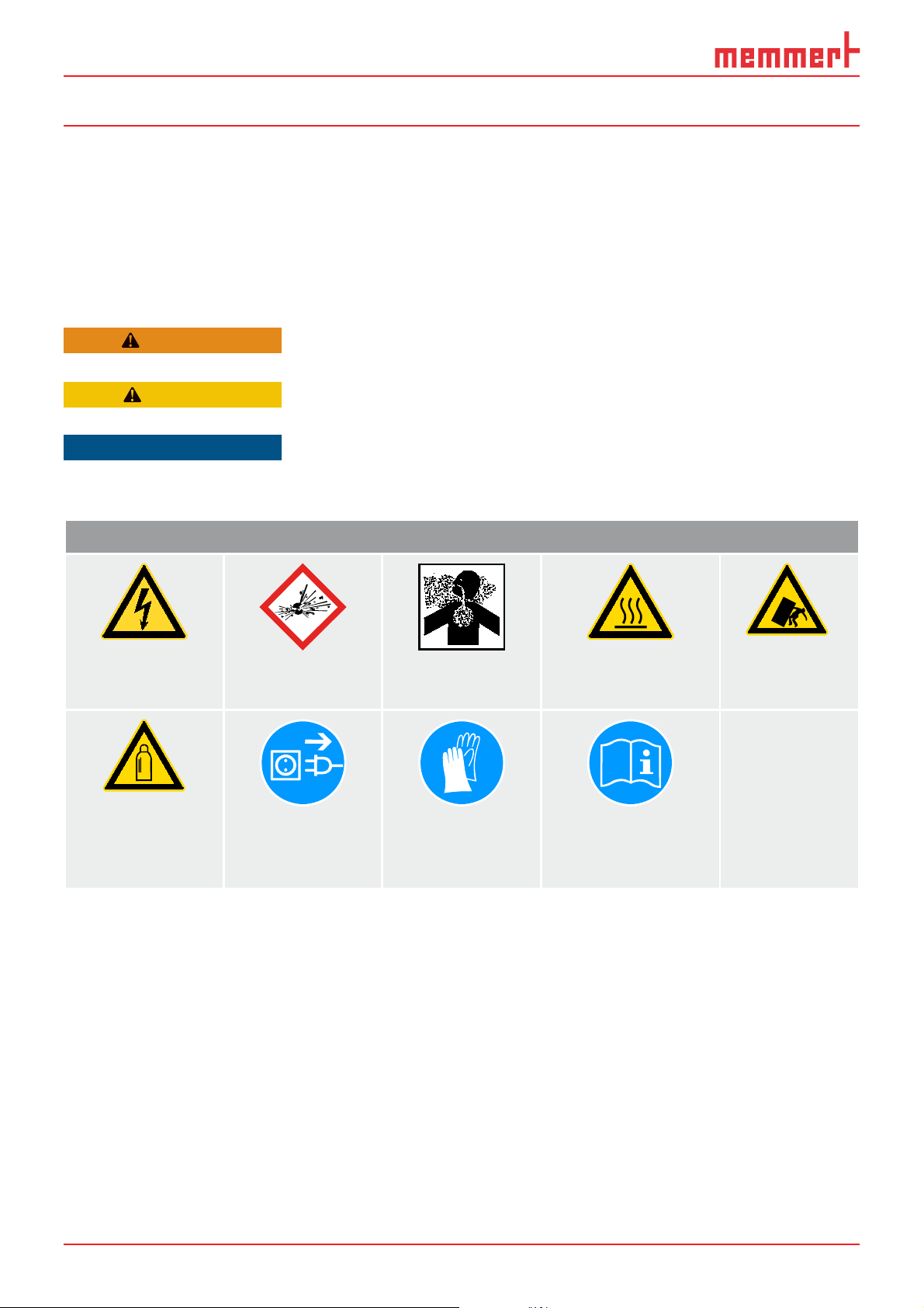
1.1.2 Signs used
Signs used
Danger of elec-
trocution
Warns of a dangerous situation that might lead to death or
serious injuries
Warns of a dangerous situation that might lead to moderate
or minor injuries
Warns of material damage
Danger of
explosion
Dangerous
gases/vapours
Danger of burns Danger of
toppling over
Gas bottles
Disconnect the
mains plug
Wear gloves Observe informa-
tion in separate
manual
1.2 Product safety and dangers
The appliances described in this manual are technically sophisticated, manufactured
using high-quality materials and subject to many hours of testing in the factory. They
reflect the state of the art and comply with recognised technical safety regulations. However, there are still risks involved, even when the appliances are used as intended. These
are described below.
6 D39374 | Date 08/2018
Page 7
For your safety
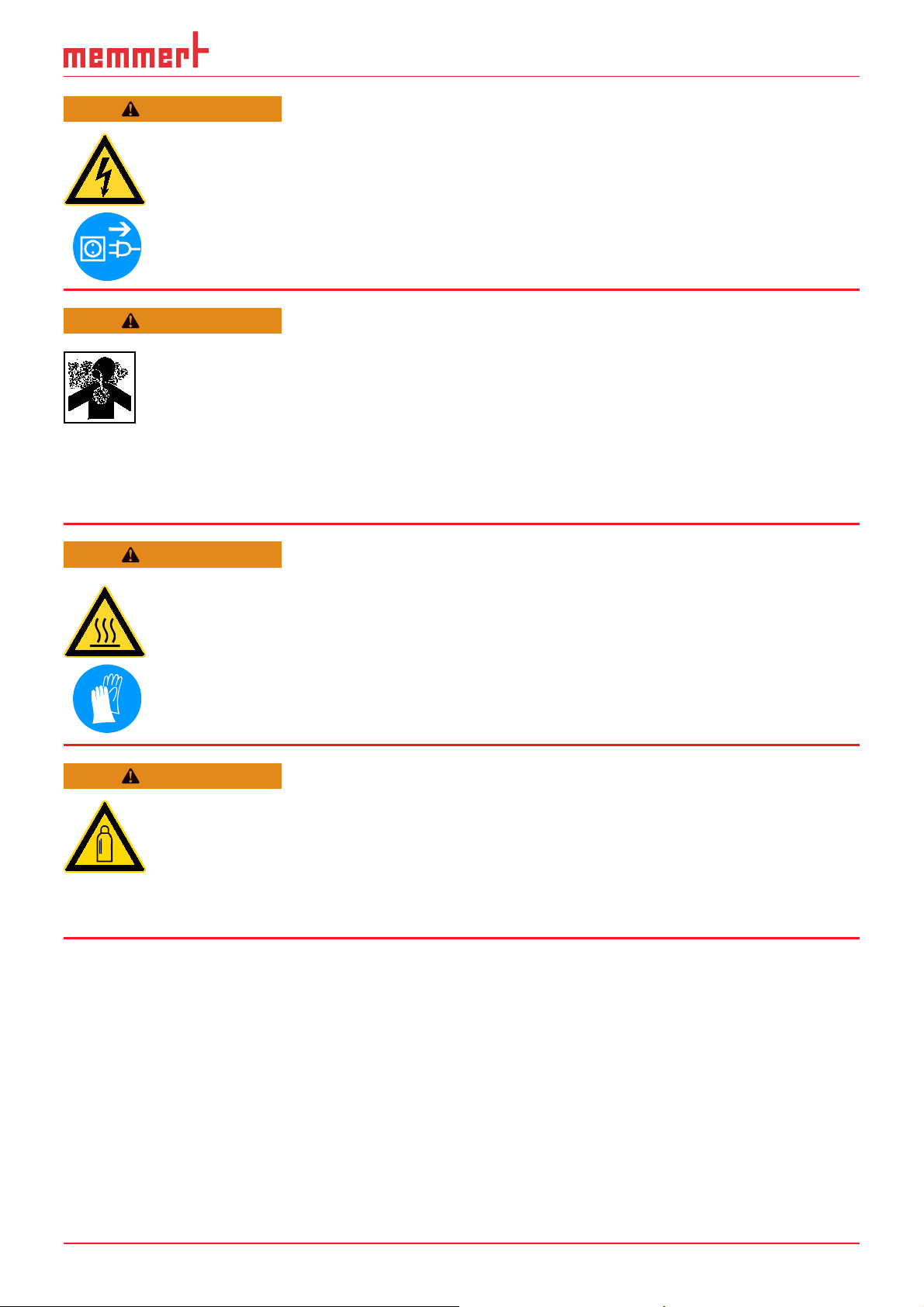
WARNING
After removing covers, live parts may be exposed. Touching these
can lead to an electric shock. Disconnect the mains plug before
removing any covers. Work on the electrical system must only be
performed by qualifi ed electricians.
WARNING
Toxic gases or vapours may be produced in certain applications.
These can escape from the vacuum pump into the room. This can
injure people nearby.
The appliance may only be used for such applications if a suction is
attached to the vacuum pump used, which reliably keeps toxic gases
or vapours away from people. Observe the respective national regulations for occupational safety and environmental protection.
WARNING
Depending on operation, the surfaces in the interior of the appliance
and the chamber load may still be very hot after the appliance is
switched off. Touching these surfaces can cause burns. Wear heatresistant protective gloves or wait until the appliance cools down
before touching.
WARNING
Gas bottles may burst or explode at high temperatures. Keep the
gas bottles away from open fl ames. Store gas bottles below 50 °C
and ensure that the location is always well ventilated. Prevent water
from penetrating as well as backfl ow into the gas bottles. It is es-
sential that you read the safety notes and instructions of the gas
supplier.
1.3 Requirements of the operating personnel
The appliance may only be operated and maintained by persons who are of legal age and
have been instructed accordingly. Personnel who are to be trained, instructed or who
are undergoing general training may only work with the appliance under the continuous
supervision of an experienced person.
Repairs may only be performed by qualified electricians. The regulations in the separate
service manual must be observed.
D39374 | Date 08/2018 7
Page 8
For your safety
ONN
1.4 Responsibility of the owner
The owner of the appliance
► is responsible for the flawless condition of the appliance and for it being operated in
accordance with its intended use (see page 8);
► is responsible for ensuring that persons who are to operate or service the appliance
are qualified to do this, have been instructed accordingly and are familiar with the
operating instructions at hand;
► must know about the applicable guidelines, requirements and operational safety
regulations, and train staff accordingly;
► is responsible for ensuring that unauthorised persons have no access to the appli-
ance;
► is responsible for attaching a suction to the vacuum pump used if toxic gases or
vapours may arise as a result of the process;
► is responsible for ensuring that the maintenance plan is adhered to and that mainte-
nance work is carried out properly (see page 63);
► has to ensure that the appliance and its surroundings are kept clean and tidy, for
example through corresponding instructions and inspections;
► is responsible for ensuring that personal protective clothing is worn by operating
personnel, e.g. work clothes, safety shoes and protective gloves.
1.5 Changes and alterations
No unauthorised changes or alterations may be made to the appliance. No parts may be
added or inserted which have not been approved by the manufacturer.
Unauthorised changes or alterations result in the CE declaration of conformity losing its
validity, and the appliance may no longer be operated.
The manufacturer is not liable for any damage, danger or injuries that result from unauthorised changes or alterations, or from non-compliance with the provisions in this
manual.
1.6 Behaviour in case of malfunctions and irregularities
The appliance may only be used in a flawless condition. If you as the operator notice irregularities, malfunctions or damage, immediately take the appliance out of service and
inform your superior.
You can find information on troubleshooting from page 44.
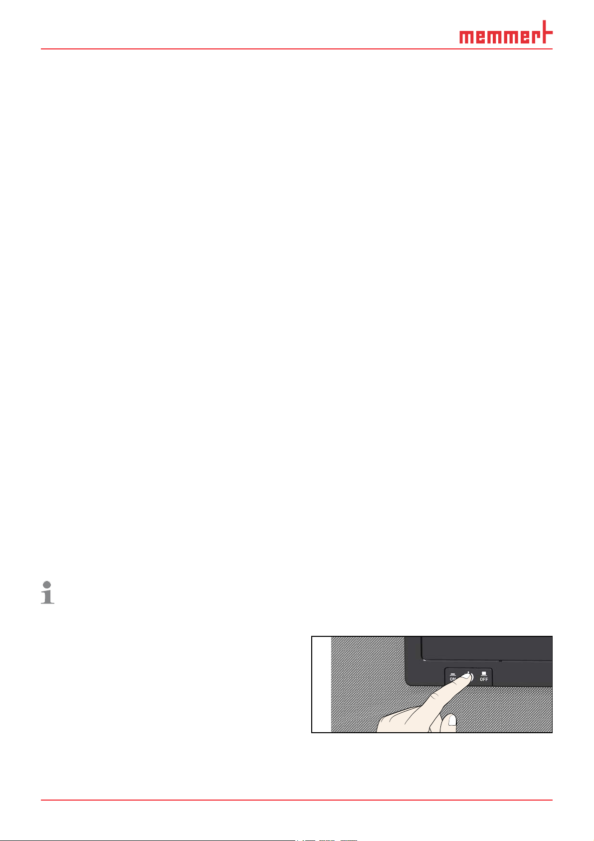
1.7 Switching off the appliance in an emergency
Press the main switch on the ControlCOCKPIT
(Fig. 1) and disconnect the power plug.
This disconnects the appliance from the
power supply at all poles.
Fig. 1
Switch off the appliance by pressing the
main switch
8 D39374 | Date 08/2018
ON
Page 9
2. Design and description
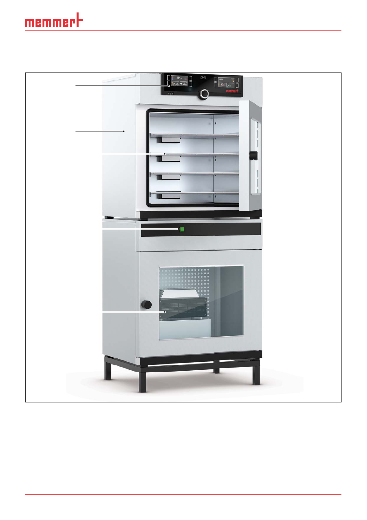
2.1 Design
1
2
3
Design and description
4
5
Fig. 2 Design
1 ControlCOCKPIT with capacitive function keys and LCD displays (see page 32)
2 Vacuum oven VO
3 Thermoshelves
4 Main switch Pump module
5 Pump module
D39374 | Date 08/2018 9
Page 10

Design and description
2.2 Intended use
Vacuum ovens VO are used for drying, testing, moisture determination, airtight storage,
curing and degassing of substances or materials under vacuum, which are used in the
procedures and specifications described in the operating instructions.
The appliance is not explosion-proof. The use of explosive substances or materials is abusive and can lead to hazards or damage. The appliance may only be loaded with materials and substances which cannot form any explosive vapours at the set temperature and
which cannot explode, burst or ignite.
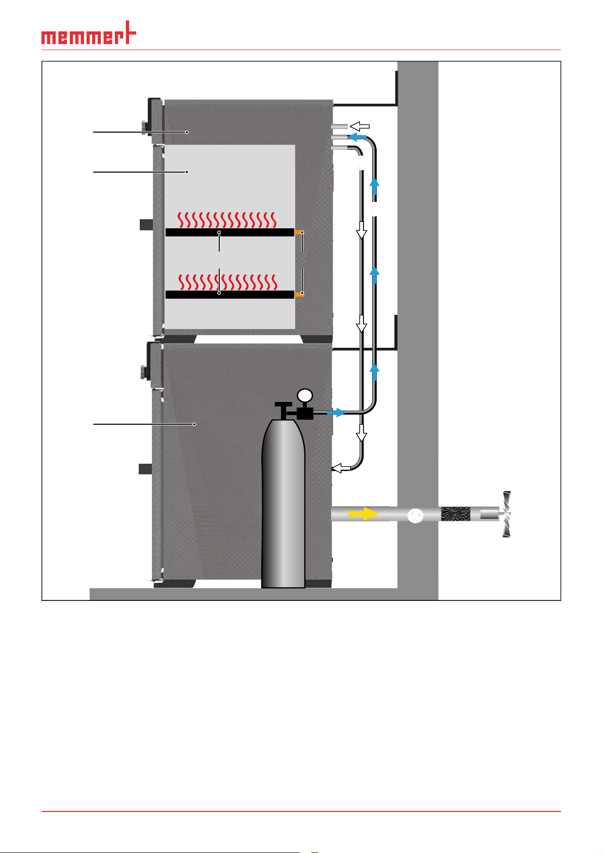
2.3 Function
The devices of the VO series (Fig. 3 1) can generate a vacuum in working chamber3 in
conjunction with Memmert pump module 2 or another suitable vacuum pump. The
vacuum inlet on the back of appliance 4 evacuates the working chamber through the
pump.
Optionally, the working chamber can be supplied with inert gas through a connection on
the rear of the appliance 56.
For temperature control thermal plates with electronic contacts are inserted into tube 7.
If the electronic contacts are connected to the connections in rear panel 8, the thermoshelves can emit heat by direct contact with the load.
If toxic gases or vapours may be produced in the intended application, these must be
safely discharged by the customer via an extraction system and cleaned if necessary 9.
10 D39374 | Date 08/2018
Page 11
1
Design and description
0
3
2
4
6
7 8
0
5
N
2
He
Ne
Ar
Kr
Xe
9
Fig. 3 Function of vacuum ovens VO in conjunction with a pump module
1 VO
2 Vacuum pump
3 VO working chamber
4 Hose connection between VO and vacuum pump
5 Gas cylinder ( inert gas, optional)
6 Inert gas supply
7 Thermoshelves
8 Contacting the Thermoshelves in the appliance
9 Suction (required if toxic gases or vapours may be produced as a result of the process)
10 Wall mounting (tilt protection, see page 23)
D39374 | Date 08/2018 11
Page 12

Design and description
2.4 Materials used
Component Materials
Housing Stainless steel (W.St.Nr. 1.4016)
Piping Stainless steel (W.St.Nr. 1.4571)
Interior Stainless steel (W.St.Nr. 1.4404), which stands out
through its high stability, optimal hygienic properties and corrosion-resistance towards many (but not
all!) chemical compounds (caution for example with
chlorine compounds).
Thermoshelves Aluminium. The vulcanised heating mat covered with
stainless steel on the underside of the thermoshelf is
made of silicone.
Plug connection of thermoshelf
and rear flange socket
Seals in solenoid valves and
flange sockets
Door seal Silicone
A resistance table for all these materials can be requested from the company MEMMERT.
Ryton R4 (GF-PPS plastic) or PEEK-GF30
Fluorocarbon FKM / FPM (Viton)
2.5 Electrical equipment
► Operating voltage and current consumption: See nameplate
► Protection class I, i.e. operating insulation with PE conductor in accordance with EN
61010
► Protection class IP 20 acc. to EN 60529
► Interference suppression acc. to EN 55011 class B
► Appliance fuse: Safety fuse 250 V/15 A, quick-blow
► The temperature sensor is equipped with a 100 mA miniature fuse.
2.6 Connections and interfaces
2.6.1 Electrical connection
This appliance is intended for operation on an electrical power system with a system
impedance Z
operator must ensure that the appliance is operated only on an electrical power system
that meets these requirements. If necessary, you can ask your local energy supply company what the system impedance is.
Observe the country-specific regulations when making connections (e.g. in Germany DIN
VDE 0100 with earth leakage circuit breaker).
12 D39374 | Date 08/2018
of a maximum of 0.292 ohm at the point of transfer (service line). The
max
Page 13
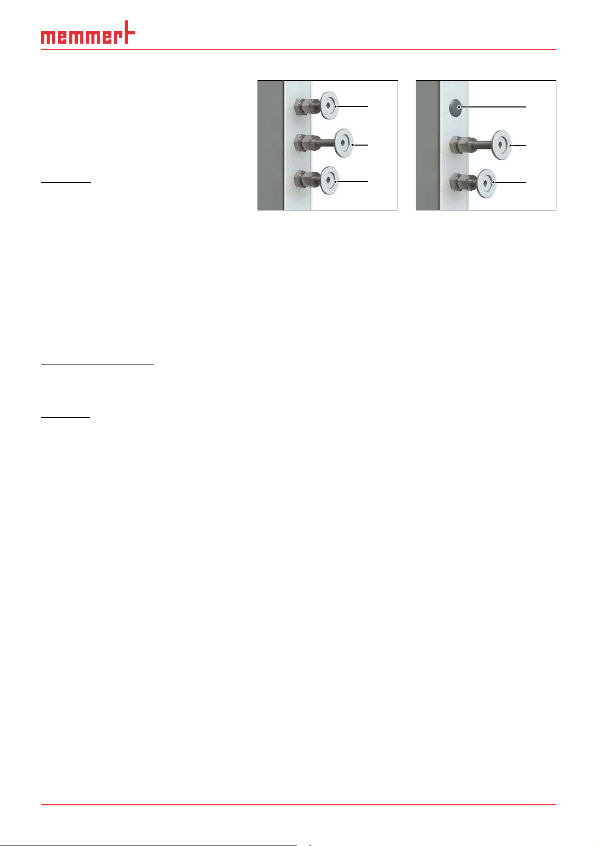
2.6.2 Fresh air, inert gas and vacuum connection
At the left rear post are the
connections for the inlet of fresh
air or inert gas (optional) and the
connection for the vacuum
pump (DN 16 KF, Fig. 4 and Fig.
5).
1
2
Design and description
1
2
Fresh air
The fresh air connection has two
functions. On the one hand,
the device is ventilated via the
connection and thus the negative pressure is adapted to the
atmospheric pressure. On the
other hand, the connection is
opened by the appliance controller for a very short time in
order to fine-tune the negative
pressure.
Fig. 4 Connections
on the back of VO 49
Premium and VO 101
Premium appliances
1 Fresh air supply
2 Inert gas connection
3 Vacuum pump con-
nection
3
Fig. 5 Connections
on the back of VO 29
Premium units and all
standard appliances
1 without function
(blanking plug)
2 Fresh air supply
3 Vacuum pump con-
nection
3
Inert gas (optional)
By applying inert gas to the working chamber, a protective atmosphere can be created
which protects the load from contact with ambient air.
Vacuum
The vacuum connection is designed as an ISO-KF connection of size DN 16. Either the
supplied pump module or another suitable external vacuum pump are connected to it.
When using an external vacuum pump, make sure that the pump is suitable for the material being fed and the desired process.
Required parameters of a suitable pump:
► Pumping speed > 30 Nl/min
► Final vacuum ≤ 3 mbar
► chemical-resistant version
► temperature resistant (exhaust gas temperature like working temperature)
D39374 | Date 08/2018 13
Page 14
Design and description
2.6.3 Communication interfaces
The communication interfaces are intended for appliances which meet the requirements
of IEC 60950-1.
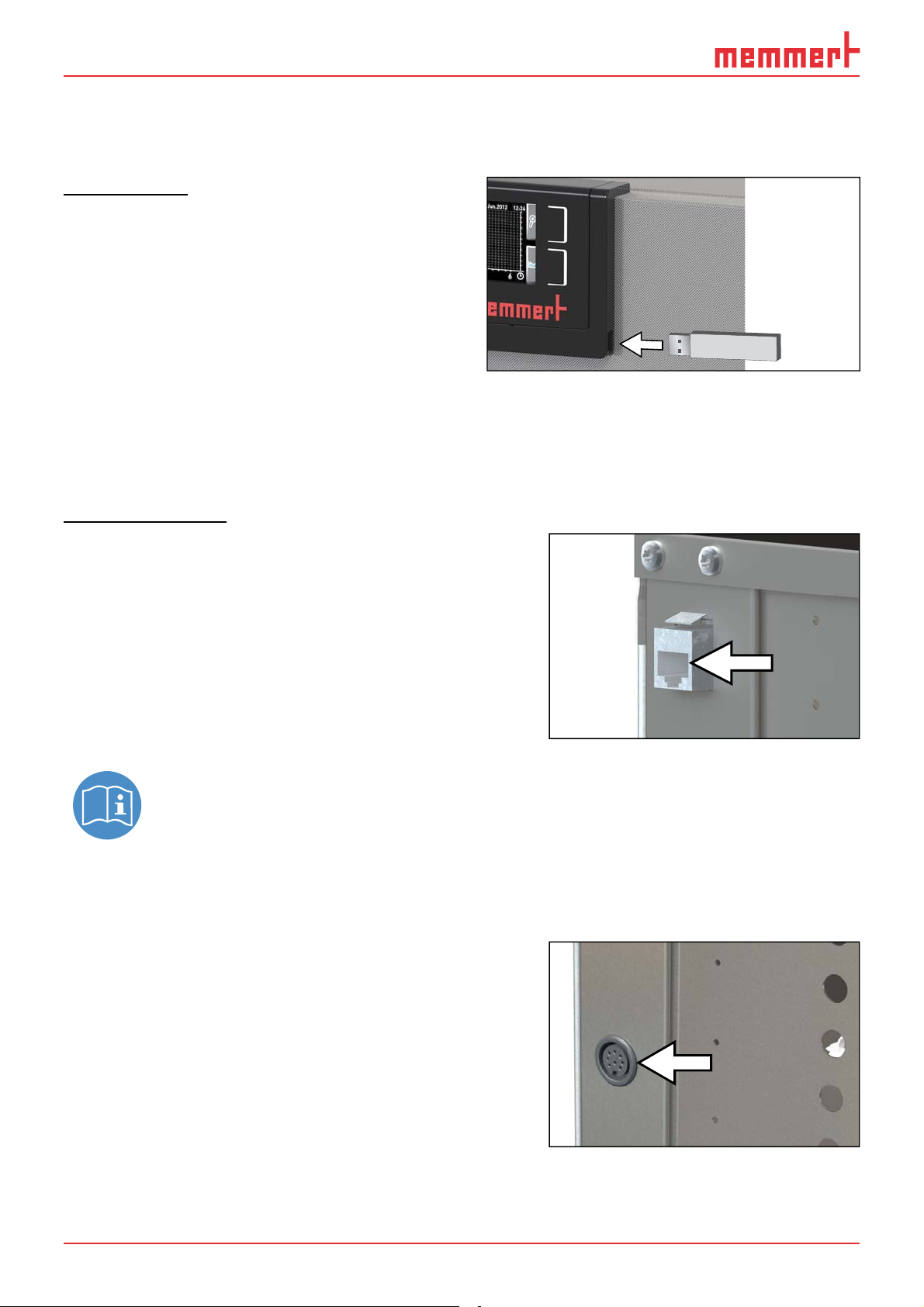
USB interface
The appliance is fitted by default with a
USB port in accordance with the USB specification. This way, you can
► transfer software stored on a USB stor-
age medium to the appliance (see page
59).
► export protocol logs from the appliance
to a USB storage medium (see page
61).
Fig. 6 USB interface
► transfer user ID data stored on a USB storage medium to the appliance (see page
62).
The USB port is located on the right of the ControlCOCKPIT (Fig. 6).
Ethernet interface
The appliance can be connected to a network via the
Ethernet interface, so that you can transfer
programmes created with the AtmoCONTROL
software to the appliance and read out protocols.
The Ethernet interface is located on the rear of
the appliance (Fig. 7).
For identification purposes, each appliance connected must have its own unique IP address.
Configuration of the IP address is described on
page 50.
You will find a description of how to transfer programs via Ethernet in the
enclosed AtmoCONTROL manual.
The appliance can be directly connected to a computer / laptop using an optional USB to
Ethernet converter (see Scope of delivery on page 18).
Fig. 7 Ethernet interface
2.6.4 Switching output for external vacuum pump purge valve and pump control
The 8-pin switching output on the rear right post
(Fig. 8) is used to control the vacuum pump of
the optional pump module (PM) through the
vacuum oven (VO). The switching output is
backwards-compatible with the 3-pole contact of
older pump modules. For this purpose, plug the
3-pole cable into the 8-pole contact.
Fig. 8 Switching output
14 D39374 | Date 08/2018
Page 15
Design and description
Vacuum pump rinsing valve
When drying feed materials with a high moisture content, the pump capacity may decrease during prolonged operation due to condensation in the pump heads. The diaphragms are blown free by briefly flushing the pump heads with fresh air.
This improves the efficiency of the drying process. In combination with the optionally
available pump modules PM29, PM49 and PM101, this cyclical flushing takes place automatically when the pump output decreases. The drying process is thus faster and more
energy-saving and the pump is protected.
Speed control and switch-off of the vacuum pump
After completing a drying program or after a long period of operation without a vacuum
request from the controller, the vacuum pump installed in the pump module (PM) is
switched off via the control line. The demand-controlled pump speed control saves
energy, is low-noise and increases the service life of the vacuum pump by protecting the
pump diaphragms.
Note: A control signal switches off the pump module (PM) installed in the optional
vacuum pump. The operating light in the main switch of the pump module also lights up
if the vacuum pump has been switched off via the control line.
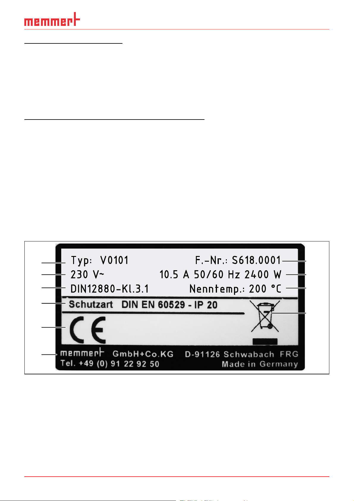
2.7 Designation ( nameplate)
The nameplate (Fig. 9) provides information about the appliance model, manufacturer
and technical data. It is attached to the front of the appliance, on the right behind the
door.
1
2
3
4
5
6
Typ: V0101 F.-Nr.: S618.0001
230 V
~
10.5 A 50/60 Hz 2400 W
DIN12880-Kl.3.1 Nenntemp.: 200 °C
10
9
8
7
Fig. 9 Nameplate (example)
1 Type designation
2 Operating voltage
3 Applicable standard
4 Protection type
5 CE conformity
D39374 | Date 08/2018 15
6 Address of manufacturer
7 Disposal note
8 Temperature range
9 Connection / power ratings
10 Appliance number
Page 16

Design and description
p
p
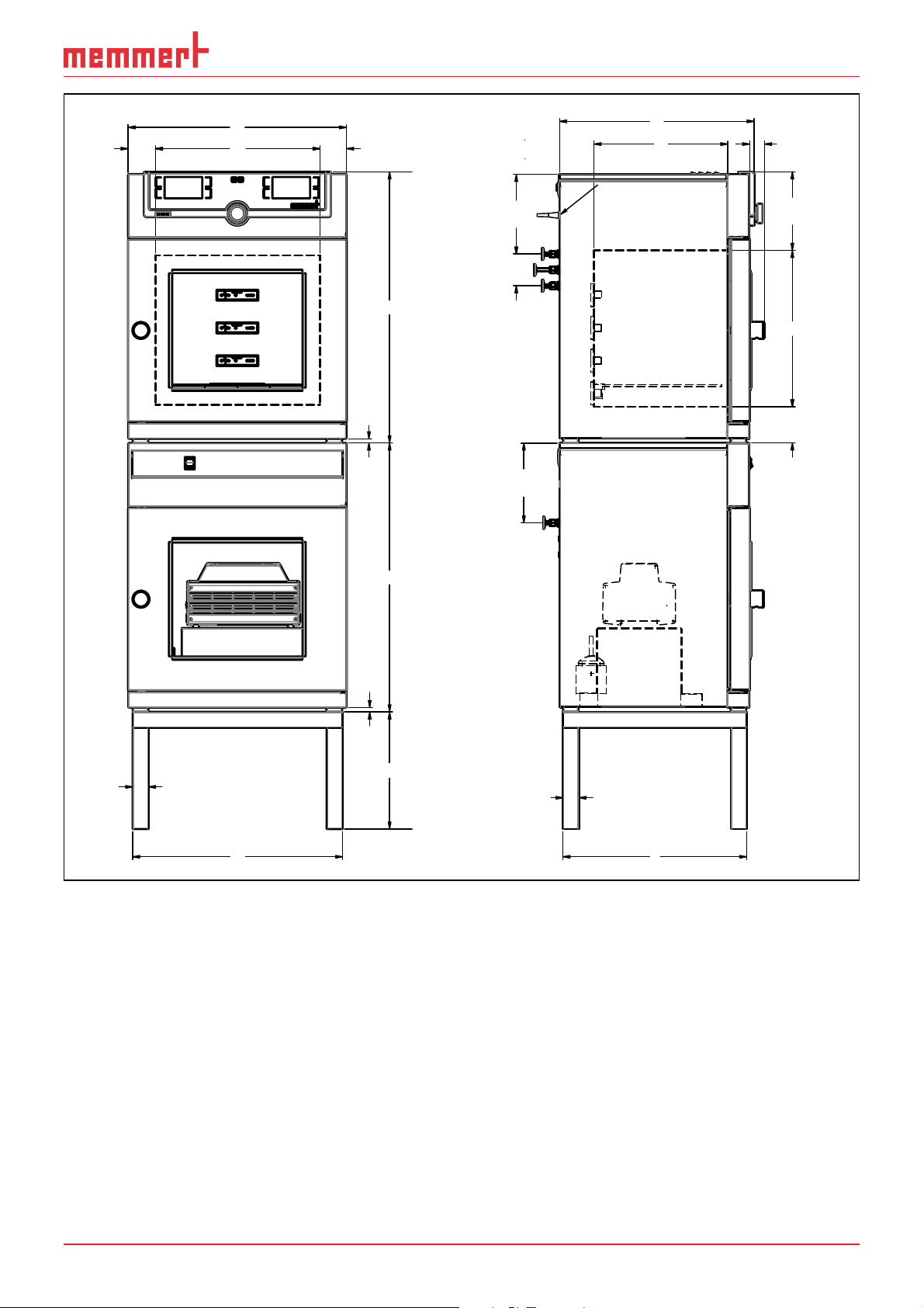
2.8 Technical data
Appliance size 29 49 101
Appliance width D1 [mm] 550 550 710
1
Appliance height E
Appliance depth F
th of door lock [mm] 38
De
Chamber width A
Chamber height B
Chamber depth C
[mm] 600 680 760
1
[mm] 400 480 550
1
[mm] 385 385 545
1
[mm] 305 385 465
1
[mm] 250 330 400
Width G [mm] 529 529 689
Base
Height H [mm] 450 290 130
Depth I [mm] 383 463 533
Chamber volume [litres] 29 49 101
Weight [kg] 62 74 100
Power [W] 820 2020 2420
Current consumption [A] 230 V, 50/60 Hz 3.6 8.8 10.5
max. number of thermoshelves
Standard 1 2 2
Premium 2 4 4
max. load per Thermoshelf [kg] 20
max. load per appliance [kg] 60 80 150
Adjustment range 20 °C to 200 °C
Temperature
Adjustment precision 0.1 K
Operating temperature range
From 5° C to 200° C (including ambient
tem
erature)
Adjustment range 5 mbar - 1100 mbar
Pressure
1
See Fig. 10
2
The minimum temperature depends on the outdoor temperature (see ambiant conditions on page
18).
Adjustment precision 1 mbar
-2
Leak rate ≤ 0.5 x 10
mbar 1/sec
16 D39374 | Date 08/2018
Page 17
Design and description
D
80 80
A
12
200
80
200
F
C
x
38
200
B
80
E E
12
40
G
H
40
I
Fig. 10 Dimensions
2.9 Declaration of conformity
You can download the EC declaration of conformity of the appliance online:
English: http://www.memmert.com/en/service/downloads/ce-statement/
German: http://www.memmert.com/de/service/downloads/eg-konformitaetserklaerung/
D39374 | Date 08/2018 17
Page 18
Design and description
2.10 Ambient conditions
► The appliance may only be used in enclosed areas and under the following ambient
conditions:
Ambient temperature
Humidity rh max. 80 % non-condensing
Overvoltage category II
Pollution degree 2
Altitude of installation max. 2,000 m above sea level
+5 ºC to +40 ºC
► The appliance may not be used in areas where there is a risk of explosion. The ambi-
ent air must not contain any explosive dusts, gases, vapours or gas-air mixtures. The
appliance is not explosion-proof.
► Heavy dust production or aggressive vapours in the vicinity of the appliance could
lead to sedimentation in the interior and, as a consequence, could result in short
circuits or damage to electrical parts. For this reason, sufficient measures to prevent
large clouds of dust or aggressive vapours from developing should be taken.
2.11 Scope of delivery
► Power cable
► Tilt protection
► Thermoshelves (Standard and Premium VO 29 1 shelf; Premium VO 49 and VO 101 2
shelves)
► USB storage medium with software and AtmoCONTROL manual
► the operating instructions at hand
► Calibration certificate
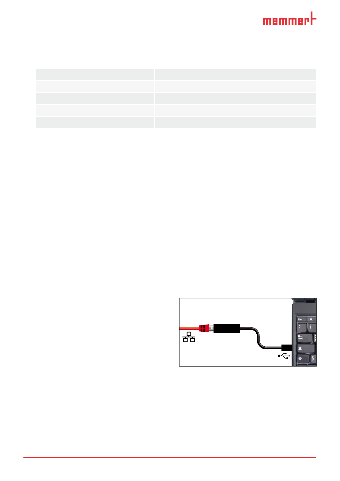
2.12 Optional accessories
With an Ethernet-USB converter (Fig. 11) it is
possible to connect the Ethernet port of
the appliance (see page 14) to the USB
port of a PC/laptop.
Fig. 11 USB to Ethernet converter
18 D39374 | Date 08/2018
Page 19
Delivery, transport and setting up
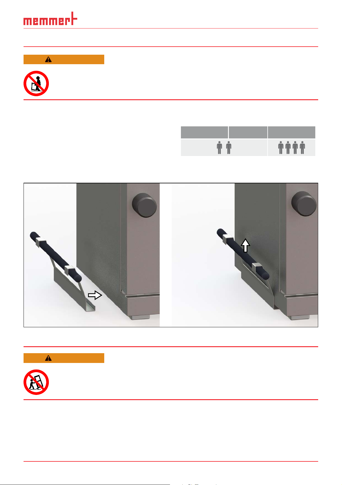
3. Delivery, transport and setting up
WARNING
The appliance may only be lifted and placed with a special lifting device. This lifting device must be used for lifting and carrying. Without
a lifting device there is a great risk of injury!
The lifting device can be purchased from the dealer. Either the dealer sends the device to
the customer or the dealer assembles the appliances himself with the device.
To set up appliances of the sizes 29 and 49,
at least two persons, for appliances of size
101, four persons are needed.
To lift the appliance, guide the lifting device
under the appliance from both sides (Fig. 12)
and lift the appliance.
29 49 101
Fig. 12 Lifting equipment
WARNING
There is a risk of tipping when stacking on a pump module. Do not
move stacked device combinations.
D39374 | Date 08/2018 19
Page 20

Delivery, transport and setting up
3.1 Delivery
The appliance is packed in cardboard and is delivered on a wooden palette.
3.2 Transport
The appliance can be transported in three ways:
► With a forklift truck; move the forks of the truck entirely under the pallet.
► On a manual pallet jack
► (only with the lifting device)
3.3 Unpacking
To avoid damage, do not unpack the appliance until you reach the installation site.
Remove the cardboard packaging by pulling it upwards or carefully cutting along an
edge.
3.3.1 Checking for completeness and transport damage
► Check the delivery note to ensure that the scope of delivery is complete.
► Check the appliance for damage.
If you notice deviations from the delivery note, damage or irregularities, do not put the
appliance into operation but inform the haulage company and the manufacturer.
3.3.2 Remove the transportation lock
Remove the transportation lock. It is located between the door hinge, door and frame
and has to be removed after opening the door.
3.3.3 Disposing of packaging material
Dispose of the packaging material (cardboard, wood, foil) in accordance with the applicable disposal regulations for the respective material in your country.
3.4 Storage after delivery
If the appliance is first to be stored after delivery: Read the storage conditions from page
64.
20 D39374 | Date 08/2018
Page 21
Delivery, transport and setting up
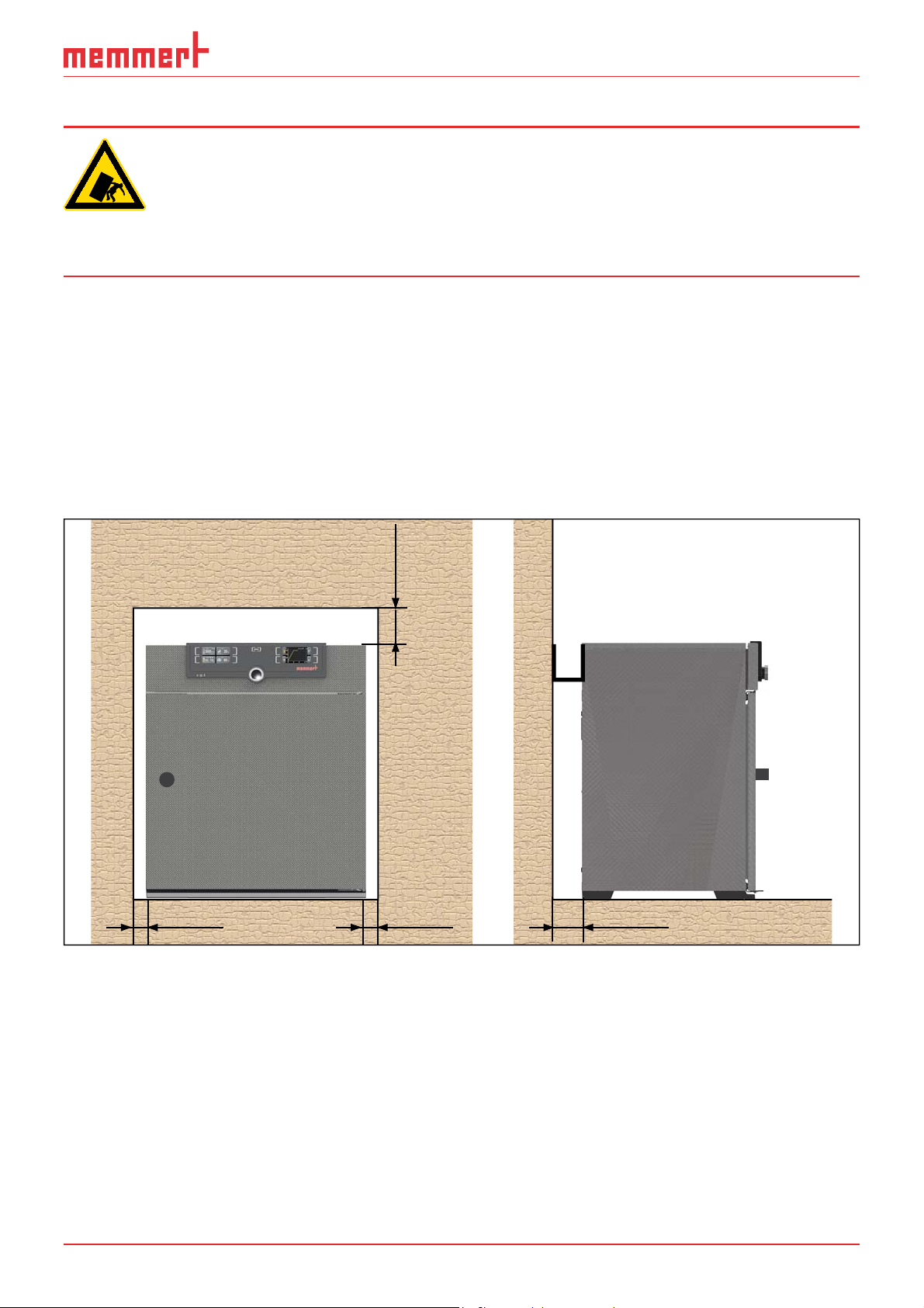
3.5 Setting up
Warning!
Stacked combinations of appliances can tip over due to their centre
of gravity and injure you or someone else. Always attach the appliance to a wall with the tilt protection (see page 23). In case there
is not enough space, do not put the appliance into operation and do
not open the door. Contact the Memmert service (see page 2).
3.5.1 Preconditions
The installation site must be flat and horizontal and must be able to reliably bear the
weight of the appliance (see "Technical data" on page 16). Do not place the appliance
on a flammable surface.
A 230 V power connection must be available at the installation site.
The distance between the wall and the rear of the appliance must be at least 15 cm. The
clearance from the ceiling must not be less than 20 cm and the side clearance from walls
or nearby appliances must not be less than 5 cm (Fig. 13). Sufficient air circulation in the
vicinity of the appliance must be guaranteed at all times.
FP
FP FP FP
Fig. 13 Minimum clearance from walls and ceiling
D39374 | Date 08/2018 21
Page 22

Delivery, transport and setting up
3.5.2 Installation options
Setting up Comments
Bottom
Table
Check the load capacity first
Stacked
maximum one VO on one pump module; mounting material (feet) is
supplied
Sub frame
Sub frame (without castors)
22 D39374 | Date 08/2018
Page 23

Delivery, transport and setting up
3.5.3 Tilt protection
Mount onto a wall the device with the tilt protection pre-assembled on the back:
1. Remove the screw right at the bottom from the tilt protection (Fig. 15).
2. Turn the tilt protection upwards by 90° twice (Fig. 14).
3. Drill a hole, insert a dowel and screw the tilt protection to a suitable wall (Fig. 16).
Fig. 14 Remove the
screw right at the bottom
from the tilt protection
Fig. 15 Turn the tilt
protection upwards
Fig. 16 Screw the tilt protection
onto the wall
D39374 | Date 08/2018 23
Page 24

Delivery, transport and setting up
3.5.4 Adjusting doors
Due to the conditions at the installation site, it may be necessary to adjust the doors.
Adjusting the door in height
1. Open set screw on the front side of the door hinge with Allen key size 2 (Fig. 17).
2. Turn the door bearing (eccentric) clockwise or counter-clockwise with a slotted screwdriver as required (Fig. 18).
Top hinge
Clockwise down Clockwise up
Counter-clockwise up Counter-clockwise down
Fig. 17 Set screw
3. If the doors are adjusted, clamp the set screw again.
Fig. 18 Turn the collar of the bearing on
the slot
Bottom hinge
Set distance from door to appliance
NOTICE
► The distance between door and seal should be chosen so that the door presses
against the seal. If the distance
between door and seal is too great,
the appliance may leak.
1. Loosen the Phillips screw of the locking bolt holder on the lower cross
frame with a screwdriver (Fig. 19).
2. Move the locking piece inwards or
outwards.
3. Fasten the locking piece with the Phillips screwdriver.
Fig. 19 Locking bolt holder
24 D39374 | Date 08/2018
Page 25

Putting into operation
4. Putting into operation
NOTICE
► When putting the appliance into operation for the first time, do not leave it unat-
tended until it has reached a steady state.
4.1 Connecting the appliance
4.1.1 Connection to the electrical supply
WARNING
Condensation in the electrical components may cause short circuits.
After transporting or storing the device under humid conditions, remove it from its packaging and let it ventilate for at least 24 hours in
normal environmental conditions. Do not connect the device to the
mains power during this time.
Caution:
Observe the country-specific regulations when making connections (e.g. DIN VDE
0100 with earth leakage circuit breaker, in Germany). Observe the connection and
power ratings (see nameplate and "Technical Data" on page 16). Make sure to
establish a safe PE conductor connection.
Place the power cable so that
► it is easily accessible at all times and can be pulled off quickly, for example in case of
interference or an emergency;
► it does not represent a trip hazard;
► it cannot come into contact with any hot parts.
Plug the provided power cable into the rear of the appliance
and connect it to a CEE 7/4 socket. (Fig. 17).
Fig. 17 Network connection
D39374 | Date 08/2018 25
Page 26

Putting into operation
4.1.2 Connecting the pump module or vacuum pump
Use the following for the connection
between the device and pump
module, the supplied connecting
elements and the supplied
vacuum hose.
Connect the vacuum connection
to the back of the unit (Fig. 18
and Fig. 19 3) to the vacuum
pump connection of the pump
module or another suitable
vacuum pump using the connecting hose.
NOTICE
When using an external vacuum
pump, make sure that it is suitable for the material being fed
and the desired process. The
pump must meet the following requirements:
Fig. 18 Connections
on the back of VO 49
Premium and VO 101
Premium appliances
1 Fresh air supply
2 Inert gas connection
3 Vacuum pump con-
nection
1
2
3
Fig. 19 Connections
on the back of VO 29
Premium units and all
standard appliances
1 without function
(blanking plug)
2 Fresh air supply
3 Vacuum pump con-
nection
1
2
3
► Pumping speed > 30 Nl/min
► Final vacuum ≤ 3 mbar
► chemical-resistant version
► temperature resistant (exhaust gas temperature like working temperature)
26 D39374 | Date 08/2018
Page 27

4.1.3 Connect inert gas (only with inert gas connection)
WARNING
Danger of explosion and poisoning when introducing gases/materials
other than inert gas. Only inert gas (nitrogen, helium, neon, argon,
krypton) may be introduced into the appliance through the gas connection on the rear of the appliance.
WARNING
Gas bottles may burst or explode at high temperatures. Keep the gas
bottles away from open fl ames. Do not store gas bottles at or above
50 °C and ensure that the location is always well-ventilated. Prevent
water from penetrating as well as backfl ow into the gas bottles. It is
essential that you read the safety notes and instructions of the gas
supplier.
CAUTION
Putting into operation
When operating with inert gas, the device releases small quantities
of the gas used into the environment. Make sure that the room is
suffi ciently ventilated.
Connect an inert gas cylinder (pressure reducer) with a connecting hose with DN16KF
connection to the connection on the rear of the unit (Fig. 18 2). Set pressure reducer to
between 1.0 and 1.2 bar.
4.1.4 Fresh air supply
NOTICE
► Compressed air must not be connected to the fresh air connection.
As a rule, no connecting hose is connected to the fresh air connection. If only clean air
may be introduced into the interior, the fresh air connection can be connected by the
customer to a tank with treated air.
4.2 Install suction
The type of extraction must comply with the relevant national regulations on occupational safety and environmental protection.
Push a Norprene hose from the outside through the perforated back into the pump
stand. Open the door and connect the hose to the outlet (pressure side) of the pump
(outlet is hose nipple G1/4 for hose ID9).
D39374 | Date 08/2018 27
Page 28

Putting into operation
4.3 Insert thermoshelves
Thermoshelves can only be operated on levels with a fitted flange socket in the rear
panel.
The device is equipped with mechanical locks to secure the thermoshelves. These can
be mounted on the support rails of the thermoshelves as required. The locking prevents
unintentional loosening of the thermoshelves from the flange socket.
NOTICE
► When mounting the locking hooks, loosen a fixing screw on the support rail, which
may cause the rail to come out of the aligned position. When re-tightening the screw,
make sure that the thermoshelf can be inserted smoothly.
Mount the locking hook
1. Remove thermoshelf.
2. Release front screws on left and right, attach locking hooks and tighten slightly.
3. Check if thermoshelf can be inserted smoothly.
Secure thermoshelf
1. Slide the thermoshelf into contact with the rear panel.
2. Turn the locking hook upwards and press it backwards against the thermoshelf (Fig. 20).
3. Fasten Allen screws on both sides using an Allen
key size 3.
Remove thermoshelf
1. Loosen Allen screw with Allen key size 3 on both sides.
2. Turn the locking hook downwards (Fig. 21).
3. Pull the thermoshelf out of the flange socket.
Fig. 20 Thermoshelf locked
in place
Fig. 21 Thermoshelf lock
released
28 D39374 | Date 08/2018
Page 29

4.4 Switching on
ONN
1. Switch on suction, if installed.
2. Switch on the pump module or vacuum
pump.
3. Switch on the VO by pressing the main
switch on the front of the appliance ( Fig.
22 ).
The start-up process is shown by three animated white dots
colour, an error has occurred (see page 44).
The appliance displays are in English by default when the appliance is switched on for
the first time. You can change the language
as described from page 49 . However,
to get a basic overview of operating the
appliance, you should read the following
chapter first.
. If the dots are any other
Putting into operation
ON
Fig. 22 Switching on the appliance
D39374 | Date 08/2018 29
Page 30

Operation and control
5. Operation and control
5.1 Operating personnel
The appliance may only be operated by persons who are of legal age and have been
instructed accordingly. Personnel who are to be trained, instructed or who are undergoing general training may only work with the appliance under the continuous supervision
of an experienced person.
5.2 Opening the door
The door can only be opened at atmospheric pressure.
► To open the door, turn handle to the right (Fig. 23).
► Press door knob in to close (Fig. 24).
Fig. 23 Opening the door Fig. 24 Closing the door
Loading the appliance
WARNING
Toxic gases or vapours may be produced in certain applications.
These can escape from the pump module into the room. This can
injure people nearby.
The device may only be used for such applications if an extraction
system is installed on the pump module which reliably keeps toxic
gases or vapours away from people.
30 D39374 | Date 08/2018
Page 31

Operation and control
NOTICE
► Check the chamber load for chemical compatibility with the materials of the appli-
ance (see page 12).
► A vacuum can be built up in the working chamber of the device. Fragile loads can be
damaged by the negative pressure. Make sure that you only use material that will not
be damaged by negative pressure.
The chamber load is heated in vacuum operation exclusively
by direct contact with the inserted thermal shelves.
Before starting operation, check whether the thermoshelves are inserted and contacted. If not, insert the
required thermoshelves (see also page 28) and check
the contact on the temperature display on the ControlCOCKPIT (Fig. 25).
When loading, pay attention to the maximum permissible weight of 20 kg per shelf level.
100,4 °C 4
3
100,1 °C 2
100,2 °C 1
Fig. 25 Thermoshelves in
contact
5.3 Operating the appliance
5.3.1 ControlCOCKPIT
In manual mode, the desired parameters are entered in the ControlCOCKPIT on the front
of the appliance (Fig. 26 ). You can also make basic settings here (menu mode). Additionally, warning messages are displayed, e.g. if the temperature is exceeded. In program
mode, the parameters defined, the program description, the program segment currently
active and program duration remaining are displayed (for a more detailed description,
see page 36).
D39374 | Date 08/2018 31
Page 32

Operation and control
ONN
m
h
1 2 3 4 5 6
TEMP
TEMP
22.4
°C
37.0
Set
°C
TIMER
TIMER
30m04h
44h:44m
End
13:30 23.11.
End 14: 45
ON
°C100.2
°CSet 100.0
VACUUM
76mb
100,4 °C 4
100,1 °C 2
100,2 °C 1
Set 50 mb
3
In 1
12.09.2012 13:44
LIGHTONLIGHT
Manual mode
ON
ALARM
ALARM
min
min
000°C
16
of °C
max
max
1029 mb
000°C
auto off
+
-
99K
Fr 20.10.2010 20:31
Holz trocknen
aufheizen
09:12h
GRAPH
%rh°C
012
off
7 8 9 0 ABC D E FG
Fig. 26 ControlCOCKPIT in operating mode
1 Activation key for temperature setpoint adjustment
2 Setpoint and actual temperature display
3 Display of actual temperature and contact of the individual thermoshelves
4 Switch to menu mode (see page 48)
5 Activation key Operating mode
6 Status display
7 Activation key digital backwards counter with target time setting, adjustable from 1 minute
to 99 days
8 Main switch
9 Display digital backwards counter with target time setting, adjustable from 1 minute to 99
days
10 Setpoint and actual pressure display
11 Activation button for target pressure setting
12 Turn control for setpoint adjustment
13 Confirmation key (accepts setting made with the turn control)
14 Activation key setting the temperature and pressure monitoring
15 Display of temperature and pressure monitoring
16 Graphical representation
17 Activation key for graphical representation
5.3.2 Basic operation
In general, all settings are made according to the following pattern:
1. Activate the desired parameter (e.g.
temperature). To do so, press the cor-
responding activation key on the left
or right or the respective display. The
activated display is lined in colour, the
other displays are dimmed. The set
value is highlighted in colour.
32 D39374 | Date 08/2018
TEMP
TEMP
22.4°C
37.0°CSet
TIMER
.5°C100
Page 33

Operation and control
T
T
2. By turning the turn control to the left
or right, adjust the set value (e.g. to
180.0 ºC).
TEMP
22.4°C
180.0°CSet
3. Save the set value by pressing the con-
firmation key.
The display returns to normal and the
appliance begins adjusting to the de-
fined set value.
The settings for further parameters and functions (pressure) can be made accordingly.
If no new values are entered or confirmed for approx. 30 seconds, the appliance
automatically restores the former values.
If you want to abort the setting procedure, press the
activation key on the left or right of the display that
you want to exit. The appliance restores the former
values. Only the settings that you have confirmed by
pressing the confirmation key before cancelling the
setting procedure are accepted.
TEMP
23.2°C
Set 180
.0°C
T
5.3.3 Operating modes
The appliance can be operated in different modes:
► Manual mode: The appliance runs in permanent operation at the values set on the
ControlCOCKPIT. Operation in this mode is described in chapter 5.3.4 .
► Operation with digital backwards counter with target time setting, adjustable from 1
minute to 99 days (timer): The appliance will run at the values set until the set time
has elapsed. Operation in this mode is described in chapter .
► program mode: The appliance automatically runs program sequences which have
been defined using AtmoCONTROL software at a computer / laptop and then trans-
ferred to the appliance from a USB stick or via Ethernet. Operation in this mode is
described in chapter 5.3.6 .
► By remote control
The status display shows which operating mode or operating state the appliance is currently in. The current operating state is highlighted in colour and indicated by the text
display:
Appliance is in program mode
■ program is stopped
Appliance is in manual mode
The example on the right shows the appliance in
manual mode, identified by the coloured hand symbol.
12.Sept.2012
Manual Mode
13:44
D39374 | Date 08/2018 33
Page 34

Operation and control
► When the appliance is in timer mode, Timer active is
displayed:
► If the appliance is in remote control mode, the
symbol appears in the temperature display:
12.Sept.2012
Timer active
13:44
5.3.4 Manual mode
In this operating mode, the appliance runs in permanent operation at the values set on the ControlCOCKPIT.
TEMP
23.2°C
Set 38
.0°C
Adjustment options
As described in chapter 5.3.2 , you can set the following parameters after pressing the
corresponding activation key (in any sequence):
Temperature
adjustment range: 20 °C to 200 °C
The display on the right shows the temperatures of the individual thermoshelves and
whether they are in contact. Thermoshelf
3 is not in contact in the example on the
right.
Heating operation is indicated by the
You can select °C or °F as the temperature units displayed (see page 51).
Pressure
Setting range 5 to 1100 mbar
symbol.
100.2
TEMP
°C
°CSet 100.0
VACUUM
100,4 °C 4
100,1 °C 2
100,2 °C 1
In 1
3
The display
VO49 and 101) indicates which gas connection is cur-
rently active:
In1/In2 top right (arrow, only for Premium
76
► In1 is displayed when fresh air is open.
► In2 is displayed when inert gas is open.
► No icon is displayed if no contact is open.
Which gas connection should be active can be set in menu mode (see page 51).
If a pressure range is set above 1100 mb, the message
appears. The old actual value is retained when the confirmation key is pressed. This function is intended for extracting
chamber load material, i.e. for generating atmospheric pressure.
If a pressure range is set below 5 mb, the message low ap-
pears. The old actual value is retained when the confirmation
key is pressed. In
at maximum and there is no pressure control. The achieved
pressure depends only on the ultimate attainable vacuum of
the pump.
Low operation, the vacuum pump operates
open
VACUUM
975
Set open
VACUUM
975
Set low
mb
Set 50 mb
In 1
mb
mb
In 1
mb
34 D39374 | Date 08/2018
Page 35

Operation and control
5.3.5 Operation with digital backwards counter with target time setting,
adjustable from 1 minute to 99 days ( timer)
In timer operation, you can adjust the time the appliance runs at the set values. The appliance has to be in manual operating mode for this.
1. Press the activation key to the left of
the timer display. The timer display is
activated.
2. Turn the turn control until the desired
duration is displayed – in this exam-
ple 4 hours 30 minutes. The approxi-
mate end time is shown beneath, in a
smaller font.
Up to a duration of 23 hours 59 minutes, the time is displayed in hh:mm
(hours:minutes) format. For 24 hours and more, the format dd:hh (days:hours) is
used. The maximum duration adjustable is 99 days 00 hours.
3. Press the confirmation key to confirm.
TIMER
-
Ende
TIMER
04 mh 3
End
--h- m
9:00 23.11.
0
13:30 23.11.
The display now shows the remaining time
in a large font and the approximate end
time in a smaller font beneath. The status
display shows
4. Now, as described in chapter 5.3.2 , set the values for temperature and pressure,
which you want the appliance to operate at. The set values can be changed at any
time while the timer elapses. The changes are effective immediately.
In
Setup, you can choose if the timer should be setpoint-dependent or not. This
determines whether the timer should not start until a tolerance band around the set
temperature is reached or if it should start immediately after activation (see page
52). The
dependent.
Once the timer has finished, the display shows 00h:00m. All
functions (heating etc.) are switched off. If a fan was on, it will
continue running for a short safety period. In addition, an
acoustic alarm sounds, which can be turned off by pressing the
confirmation key.
Timer active.
symbol on the timer display indicates that the timer is set to setpoint-
TIMER
End
30m04h
13:30 23.11.
12.Sept.2012
Timer active
TIMER
End
13:44
00m00h
13:30 23.11.
D39374 | Date 08/2018 35
Page 36

Operation and control
080
To deactivate the timer, open the timer display by pressing the
activation key again and then turning the turn control to
TIMER
reduce the timer setting until --:-- is displayed. Press the
confirmation key to confirm.
5.3.6 Program mode
End
--m--h
9:00 23.11.
In this operating mode, programs saved in the appliance can be started with different
combinations of individual parameters (temperature,
Pressure) at staggered intervals,
which the appliance then automatically processes in sequence. These programs are
not created directly at the appliance but externally at a computer / laptop and using
AtmoCONTROL software. Transfer to the appliance is possible using the provided USB
storage medium or via Ethernet.
A description of how to create and save programs can be found in the separate AtmoCONTROL software manual.
Starting a program
1. Press the activation key on the right of
the status display. The current operating mode is highlighted automatically,
in this example
Manual mode ( ).
Fr 20.10.2010 20:31
%
%
17:4413.Sept.2012
Manual mode
manueller Betrieb
Activate
GRAPH
°C
off
2. Turn the turn control until the start
80
40
4
10:4412.Sept.2012
symbol is highlighted. The current
program is displayed, in this example
Test 012.
Test 012
ready
Only the program currently selected in menu mode and shown in the display can be
used. If you want to process another program, you need to activate it in menu
mode first (see description starting on page 59).
3. To start the program, press the confir-
10:4412.Sept.2012
mation key. The program is activated.
The display shows:
Test 012
Ramp 1
► the program description (in this exam-
Test 012)
ple
► the program segment description, in
this example
Ramp 1
► the current run (in case of loops)
You cannot change any parameters (e.g. the temperature) at the appliance while a
program is running. However, the displays
36 D39374 | Date 08/2018
ALARM and GRAPH can still be used.
Page 37

Cancel program
Operation and control
You can cancel an active program at any
time.
1. Press the activation key to the right of
Fr 20.10.2010 20:31
Test 012
manueller Betrieb
Ramp 3
10:4412.Sept.2012
the status display. The status display is
automatically highlighted.
2. Turn the turn control until the
symbol is highlighted.
■
stop
GRAPH
Cancel program
Test 012
3. Press the confirmation key to confirm.
The program is cancelled.
End
Test 012
A cancelled program cannot be resumed at the point it was cancelled. It must be
restarted from the beginning.
10:4812.Sept.2012
10:4912.Sept.2012
End of program
End
is shown on the display to indicate
that the program has finished.
End
Test 012
10:4912.Sept.2012
You can now
► restart the program as described
► select another program to run in menu mode (see page 59) and run it as de-
scribed.
► Return to manual mode. To do so, reactivate it by pressing
the activation key next to the status display, then turn
the turn control until the hand symbol
is highlighted
in colour and press the confirmation key.
12.Sept.2012
Manual Mode
13:44
5.4 Temperature monitoring
The appliance is equipped with multiple overtemperature protection (mechanical/electronic) in accordance with DIN 12 880. This serves to avoid damage to the chamber load
and/or appliance in case of a malfunction:
► electronic temperature monitoring (TWW)
► automatic temperature monitor ( ASF)
► mechanical temperature limiter (TB)
D39374 | Date 08/2018 37
Page 38

Operation and control
The monitoring temperature of the electronic temperature
monitoring is measured via a separate Pt100 temperature
sensor in the interior. Temperature monitoring settings are
made via the
ALARM display. The settings made apply to all
operating modes.
If temperature monitoring has been
triggered, this is indicated on the
temperature display: the actual
temperature is highlighted in red and
a
warning symbol is shown ( Fig.
27 ). The type of temperature monitoring triggered (TWW in this example) is
shown beneath the temperature.
If the acoustic alarm has been activated in menu mode (
by the speaker symbol
on the alarm display), the alarm is additionally signalled by an
Fig. 27
Temperature monitoring triggered
Sound see page 60, indicated
min
160.0°C
auto
TEMP
189.2
ALARM
°C
°CSet 180.0TWW
max
190.0°C
+
5.0K
-
189,4 °C 4
189,1 °C 2
189,2 °C 1
intermittent acoustic signal, which can be turned off by pressing the confirmation key.
Information on what to do if this happens can be found in chapter Malfunctions, warning and error messages from page 44.
Before reading how to adjust temperature monitoring (from page 39), please read the
description of the individual monitoring functions here.
3
5.4.1 Electronic temperature monitoring ( TWW)
The manually set monitoring temperature min. and max. of the electronic overtemperature control is monitored by an adjustable over/undertemperature controller (TWW)
protection class 3.1 acc. to DIN 12 880 (or over/undertemperature controller (TWW)
protection class 3.1 for UIS appliances). If the manually set monitoring temperature
is exceeded, the TWW takes overtemperature control and begins to regulate the monitoring temperature (Fig. 28).
°C
Emergency operation
Setting MAX
Set temperature
Controller error
max
t
Fig. 28 Schematic diagram of how TWW temperature monitoring works
38 D39374 | Date 08/2018
Page 39

Operation and control
5.4.2 Automatic temperature monitor ( ASF)
ASF is a monitoring device that automatically follows the set temperature setpoint within
an adjustable tolerance band (Fig. 29).
The ASF – if switched on – is automatically activated as soon as the actual temperature
value reaches 50 % of the set tolerance band of the setpoint (in the example: 180 °C -
1.5 K) for the first time (section A).
When the temperature violates the set tolerance band around the setpoint (in the exam-
ple in Fig. 29:
180 °C ± 3 K) – e.g. if the door is opened during operation (section B of illustration) –
the alarm is set off. The ASF alarm is automatically terminated as soon as 50 % of the
set tolerance band of the setpoint (in the example: 180 °C ± 1.5 K) are reached again
(section C).
If the temperature setpoint is altered, the ASF is automatically disabled temporarily (in
this example: The setpoint is changed from 180 °C to 173 °C, section D), until it reaches
the tolerance range of the new temperature setpoint (section E).
ABCDE
183 °C
183 °C
180 °C
177 °C
177 °C
176 °C
170 °C
t
ASF active
AUTO AUTO AUTO
ASF alarm
ASF active ASF active
Fig. 29 Schematic diagram of how the ASF temperature monitoring works
5.4.3 Mechanical temperature monitoring: Temperature limiter ( TB)
The appliance is equipped with a mechanical temperature limiter (TB) of protection class
1 in accordance with DIN 12 880.
If the electronic monitoring unit should fail during operation and the factory-set maximum temperature is exceeded by approx. 20 °C, the temperature limiter, as the final
protective measure, switches off the heating permanently.
5.4.4 Adjusting temperature monitoring
1. Press the activation key to the left of the
ALARM
ALARM display. The temperature set-
ting is automatically highlighted.
D39374 | Date 08/2018 39
min
100.0 °C
min
auto
000°C
ALARM
max
max
120.0°C
000°C
auto off
+
+
0.0
99K
-
-
K
Page 40

Operation and control
2. Accept the selection by pressing the
confirmation key. The
min setting (un-
dertemperature protection) is automatically activated.
ALARM
min
°C
auto
max
120.0°C1000.
+
-
0.0K
3. By turning the turn control, adjust the
desired lower alarm limit value, in the
example on the right 160 °C.
If no undertemperature protection limit
is required, set the lowest temperature.
4. Press the confirmation key to confirm.
max display (overtemperature
The
protection) is activated.
5. By turning the turn control, adjust the
desired upper alarm limit value, in the
example on the right 190 °C.
The monitoring temperature must be
set sufficiently high above the maximum
set temperature. We recommend 5 to
10 K.
min
auto
min
1600.
auto
min
1600.
auto
ALARM
°C
ALARM
°C
ALARM
°C
max
120.0°C1600.
+
-
max
120 0.
+
0.0K
-
max
190 0.
+
-
0.0K
°C
°C
0.0K
6. Accept the upper alarm limit value
by pressing the confirmation key. The
setting of the automatic temperature
monitor (ASF) is automatically activated
(
auto).
7. With the turn control, select ON () or
OFF ().
8. Press the confirmation key to confirm.
The ASF tolerance band setting is activated.
9. With the turn control, adjust the desired
tolerance band, e.g. 5.0 K.
We recommend a tolerance band of 5
to 10 K.
min
160.0°C
auto
min
160.0°C
auto
min
auto
min
160 0.
auto
ALARM
ALARM
ALARM
°C
ALARM
°C
max
190.0°C
+
0.0K
-
max
190.0°C
+
0.0K
-
max
190.0°C160 0.
+
0.3
-
max
190.0°C
+
5.0
-
K
K
40 D39374 | Date 08/2018
Page 41

Operation and control
10. Press the confirmation key to confirm.
Temperature monitoring is now active.
In menu mode you can set, whether an
acoustic signal should be triggered in
the event of an alarm (see page 60))
5.5 Pressure monitoring
If the pressure monitoring was triggered, this is indicated
by the pressure display: by the actual pressure highlighted
in red and an alarm symbol
acoustic alarm has been activated in menu mode (
see page 59, as indicated by the speaker symbol
), the alarm is additionally signalled by an intermittent
acoustic signal. Information on what to do if this happens
can be found in chapter Malfunctions, warning and error
messages from page 44.
Setting the pressure monitoring
1. Press the activation key to the left of
the
ALARM display. The temperature
monitoring setting is automatically
activated.
is shown (Fig. 30). If the
Sound,
ALARM
min
160.0°C
auto
max
190.0°C
+
5.0K
-
VACUUM
586
In 1
mb
Set 500 mb
Fig. 30
Pressure monitoring triggered
ALARM
ALARM
min
100.0 °C
min
auto
000°C
max
max
120.0°C
000°C
auto off
+
+
0.0
99K
-
-
K
2. Turn the turn control until the pressure
monitoring entry
is highlighted.
3. Accept the selection by pressing the
confirmation key. The lower alarm limit
is automatically selected.
4. By turning the turn control, adjust the
desired lower alarm limit, in the example on the right 30 mbar.
5. Accept the selection by pressing the
confirmation key. The upper alarm limit
is automatically highlighted.
min
120
min
120
min
30
min
30
ALARM
500
mb
ALARM
500
mb
ALARM
500
mb
ALARM
500
mb
max
mb
max
mb
max
mb
max
mb
D39374 | Date 08/2018 41
Page 42

Operation and control
°C
Fr 20.10.2010 20:34
12.09.2012
:
6. By turning the turn control, adjust the
min
ALARM
600
mb
max
mb
desired upper alarm limit, in the example on the right 600 mbar.
30
7. Accept the selection by pressing the
min
ALARM
600
mb
max
mb
confirmation key and leave the
Alarm
display by pressing the activation key
on the side. Pressure monitoring is
now active and triggers as soon as the
value falls below 30 mbar or exceeds
30
600 mbar.
5.6 Graph
The GRAPH display provides an overview of the chronological sequence of the setpoint
values and actual values for temperature and pressure content as a curve.
5.6.1 Temperature profi le
1. Press the activation key to
the right of the
GRAPH dis-
play. The display is enlarged
and the temperature curve
of the individual thermoshelves is displayed. The
colours correspond to those
of the thermoshelf symbols
in the temperature display.
The red curve shows, for
example, the temperature
curve of thermoshelf 1.
► To change the time frame to
be displayed: Press the activation key next to the
arrow symbols. The time
frame to be displayed can
now be changed by turning
the turn control.
100
250
80
60
40
20
0 4 8 12162024
14.00 16.00 18.00
12.09.2012
°C
100
250
80
60
40
20
0 4 8 12162024
14.00 16.00 18.00
Fr 20.10.2010 20
► To zoom the graph in or out:
2
Press the activation key next
to the magnifying glass symbol. With the turn control,
select if you want to zoom
in or out (+/–) and confirm
your selection by pressing
the confirmation key.
To close the graphical representation, press the activation key you used to activate it
again.
42 D39374 | Date 08/2018
.2010 20:34
Page 43

5.6.2 Pressure pattern
0
0
ONN
Operation and control
1. Activate graphic representa-
tion as described above and
then press the activation
key next to the parameter
selection.
2. Set the pressure with the
turn control
.
3. Press the confirmation key
to confirm. The pressure
curve is now displayed in
green. You can change the
display range as described
above, as well as extend or
reduce it.
12.09.2012
°C
100
80
60
40
20
0 4 8 12162024
14.00 16.00 18.00
Fr 20.10.2010 2
°C
100
80
60
40
20
12.09.2017
Fr 20.10.2010 2
5.7 Ending operation
WARNING
Depending on operation, the surfaces in the working chamber
and the chamber load may still be very hot after the appliance is
switched off. Touching these surfaces can cause burns. Wear heatresistant protective gloves or wait until the appliance cools down
before touching.
1. Switch off active appliance functions
(turn back the set values). Switch off
the pump module or vacuum pump.
2. Remove the chamber load (door
cannot be opened until atmospheric
pressure is reached inside the unit).
3. Switch off the VO with the main
switch (Fig. 31).
0 16.00 18.00
Fig. 31 switch off VO
ON
D39374 | Date 08/2018 43
Page 44

Malfunctions, warning and error messages
6. Malfunctions, warning and error messages
WARNING
After removing covers, live parts may be exposed. Touching these
can lead to an electric shock. Malfunctions requiring work inside the
appliance may only be rectifi ed by electricians. Observe the separate
service manual for this.
Do not try to rectify appliance errors yourself but contact the MEMMERT customer service department (see page 2) or an authorised service point.
In case of enquiries, please always specify the model and appliance number given on the
nameplate (see page 15).
6.1 Warning messages of the monitoring function
If the acoustic alarm has been activated in the menu mode (Sound, see page 60,
indicated by the speaker symbol
signalled by an intermittent acoustic signal. If the confirmation key is pressed, the
acoustic alarm can be temporarily switched off until the next alarm event occurs.
in the alarm display), the alarm is additionally
6.1.1 Temperature monitoring
Description Cause Action See
Temperature alarm and
"ASF" are displayed
TEMP
Automatic
temperature
monitor (ASF)
was triggered.
Check if the door is closed.
Close the door.
Extend the ASF tolerance band
If the alarm continues: Contact
customer service
Page
39
Page 2
185.4°C
ASF Set 190.0 °C
Temperature alarm and
"TWW" are displayed
TEMP
195
TWW Set 190.0 °C
.4°C
The adjustable
temperature
controller
(TWW) has assumed heating
control.
Increase the difference between
the monitoring and setpoint
temperature – by either increasing the max value of the temperature monitoring or decreasing the setpoint temperature.
If the alarm continues: Contact
customer service
Page
39
Page 2
Temperature alarm and
"TB" are displayed
TEMP
230.4 °C
TB
44 D39374 | Date 08/2018
The mechanical
temperature
limiter (TB)
permanently
switched off
heating.
Switch off the appliance and
leave to cool down. Contact
customer service and have the
error rectified (e.g. by replacing
the temperature sensor).
Page 2
Page 45

Malfunctions, warning and error messages
6.1.2 Pressure monitoring
Description Cause Action See
Pressure alarm and
MaxAL are displayed
VACUUM
586
Set 500 mb
Pressure alarm and
In 1
mb
MinAL are displayed
VACUUM
721
MinAL
mb
Set 800 mb
In 1
Upper pressure limit value
exceeded
Pressure below
lower limit
Vacuum pump has too little
power. Tube may be leaking or
kinked, clean, check
Speed control damaged or
intake valve does not close correctly.
Notify customer service. Page 2
6.2 Malfunctions, operating problems and appliance errors
Error description Cause of errors Rectifying errors See
Displays are dark External power supply
was interrupted
Miniature fuse, appliance
fuse or power module
faulty
Displays cannot be
activated
Displays suddenly look
different
Door cannot be
opened
Appliance locked by USER IDUnlock with USER ID Page
The appliance is in program, timer or remote
control mode (mode
"Write" or "Write +
Alarm")
Appliance is in "wrong"
mode
Vacuum in the appliance Setting the atmos-
Check the
power supply
Contact customer
service
Wait until the end of
the program or timer
mode or switch off the
remote control
Change to operating
or menu mode by
pressing the
key
pheric pressure
MENU
Page
25
Page 2
62
D39374 | Date 08/2018 45
Page 46

Malfunctions, warning and error messages
Error description Cause of errors Rectifying errors See
Error message T:E-3
in the temperature
display
TEMP
37.4°C
T:E-3 Set 37.0 °C
Error message
in the temperature
display
TEMP
AI E-3
37.4°C
AI E-3 Set 37.0 °C
Error message
in the temperature
display
E-3
Temperature operating
sensor is defective.
► Switch off appli-
ance
► Contact customer
service
Temperature monitoring
sensor is defective.
► Switch off appli-
ance
► Contact customer
service
Sensor defective ► Switch off appli-
ance
► Remove the cham-
ber load
Page 2
Page 2
TEMP
E-3 °C
Set 45.0 °C
Error message
the pressure display
VACUUM
E-7
E-7 in
mb
Set 800 mb
Pressure sensor defective.
No pressure control possible.
In 1
► Contact customer
service
Page 2
► Contact customer
service Page 2
46 D39374 | Date 08/2018
Page 47

Malfunctions, warning and error messages
Error description Cause of errors Rectifying errors See
When switching on
the appliance, the
start animation is
displayed in another
colour than white
► Cyan :
Not enough storage
space on the SD card
► Red :
The system files could
not be loaded
Contact customer
service
Contact customer
service
Page 2
Page 2
► Orange : The
fonts and images
could not be loaded
Download the firmware update from
memmert.com and
install it
6.3 Power failure
In case of a power failure, the appliance operates as follows:
In manual mode
After power supply has been restored, operation is continued with the parameters set.
The time and duration of the power failure are documented in the log memory.
In timer or program mode
In case of an interruption of the power supply of less than 60 minutes, the current programme is continued from the point at which it was interrupted. For interruptions of the
power supply longer than this, all appliance functions (heating, fan etc.) are switched off
and the air flap is opened.
In remote control mode
The previous values are restored. If a program has been initiated via remote control, it is
continued.
NOTICE
Please refer to the operating manual for the vacuum pump used in the event of a power
failure. It may need to be turned back on.
D39374 | Date 08/2018 47
Page 48

Menu mode
ONN
7. Menu mode
In menu mode, you can make basic settings, load programs and export protocols, as well
as adjust appliance parameters.
Caution:
Before changing menu settings, read the description of the respective functions on
the following pages to avoid possible damage to the appliance and/or chamber load.
To enter menu mode, press the
To exit the menu mode at any time, press the
MENU key.
MENU
key again. The appliance then returns to operating
mode. Only changes accepted by pressing the confirmation key are saved.
7.1 Overview
Press the MENU key to change between the displays in menu mode:
12 34 512141513
TIME
LANGUAGE
SETUP
ON
SIGNALTÖNE
CALIB
ZEIT UND DATUM
PROG
SOUND
PROTOCOL
USER ID
67 18 1989 1011 16 17
Fig. 32 ControlCOCKPIT in menu mode
1 Language selection activation key
2 Language selection display
3 Date and time display
4 Date and time setting activation key
5 Exit menu mode and return to operating
mode
6 Setup activation key (basic appliance set-
tings)
7 Setup display (basic appliance settings)
8 Adjustment display
9 Adjustment activation key
10 Turn control for adjustment
11 Confirmation key (accepts setting made
with the turn control)
12 program selection activation key
13 program selection display
14 Protocol display
15 Protocol activation key
16 Acoustic signal adjustment activation key
17 Acoustic signal adjustment display
18 USER ID display
19 USER ID display activation key
48 D39374 | Date 08/2018
Page 49

Menu mode
ONN
N
B
7.2 Basic operation in menu mode using the example of language
selection
In general, all settings in menu mode are done just like in operating mode: Activate the
respective display, use the turn control for setting and press the confirmation key to
accept the change. A more detailed description is provided in the following, using the
example of language selection.
1. Activate the desired parameter (in this
example the language). To do so, press
the corresponding activation key on
the left or right or the respective display. The activated display is enlarged.
If you want to exit or cancel the settings, again press the activation key
which you have used to activate the
display. The appliance returns to the
menu overview. Only the settings that
you have confirmed by pressing the
confirmation key before cancelling the
setting procedure are accepted.
2. Select the desired new setting, e.g.
Spanish (
ESPAÑOL) using the turn
control.
ENGLISH
DEUTSCH
FRANCAIS
ESPANOL
POLSKI
CESTINA
ON
ENGLISH
DEUTSCH
FRANCAIS
ESPANOL
POLSKI
CESTINA
LANGUAGE
SETUP
MAGYAR
ITALIANO
SIGNALTÖNE
MAGYAR
ITALIANO
TIME
CALIB
3. Save the setting by pressing the confir-
mation key.
4. To return to the menu overview, press
the activation key again.
You can now
► activate another menu function by
pressing the corresponding activation
key or
► return to operating mode by pressing
the MENU key.
IP address
Balance
Subnet mask
IP Adresse
Unit
Einheit
Alarm temp
Alarm Temp
Timer mode
Timer Mode
Slide-in unit
ENGLISH
DEUTSCH
FRANCAIS
ESPANOL
POLSKI
CESTINA
MAGYAR
ITALIANO
LANGUAGE
SETUP
SIGNALTÖ
TIM
CALI
D39374 | Date 08/2018 49
Page 50

Menu mode
5
All other settings can be made accordingly. The settings possible are described in the following sections.
If no new values are entered or confirmed for approx. 30 seconds, the appliance
automatically restores the former values.
7.3 Setup
7.3.1 Overview
In the SETUP display, you can set the following parameters:
► the IP address and subnet mask of the appliance's Ethernet interface (for connection
to a network)
► The units of the temperature display (°C or °F, see page 51)
► of the gas connection that should be active (1 or 2, only for appliances VO 49 Pre-
mium and VO 101 Premium)
► How the digital backwards counter with target time setting works (Timer mode, see
page 52)
► Remote control (see page 52)
► Gateway (see page 53)
If the Setup menu contains more entries than can be
displayed, this is indicated by the display "1/2". This
means that there is a second "page" of entries.
To display the hidden entries, use the turn control
to scroll beyond the lowest entry. The page display
changes to "2/2".
1/2
IP adress 255.145.136.22
Subnet mask 255.255.0.0
Unit
°C F
7.3.2 IP address and subnet mask
If you want to operate one ore more appliances in a network, each appliance must have
its own unique IP address for identification. By default, each appliance is delivered with
the IP address 192.168.100.100.
Programm negnulletsniEllokotorPtäreG efliHnekcurD
AtmoCONTROL
INP 250 Test 01
180
.0°C
i
HPP 250 Labor
37
.0°C
i
44
.4%rh
-
+-+
Programmname
Editor
Simulation Protokoll
STAND BY
151
192.168.1.216
192.168.
Setup
LAN 1: 192.168.1.233
LAN 2: 192.168.1.215
LAN 3: 192.168.1.241
Fig. 33 Operation of several appliances in a network (schematic example)
50 D39374 | Date 08/2018
Page 51

Menu mode
1. Activate the
SETUP display. The entry
IP address is automatically high-
lighted.
2. Accept the selection by pressing the
confirmation key. The first three digits
of the IP address are automatically
selected.
3. With the turn control, set the new
number, e.g. 255.
SETUP
SETUP
IP address 192.168.100.100
Balance
Subnet mask 255.255.0. 0
IP Adresse
Unit
Einheit
Inert gas
Alarm Temp
Timer mode
Timer Mode
IP address 192. 168.10 0. 100
Subnet mask 255.255. 0. 0
Unit
Inert gas
Timer mode
+30%
192.168.100.100
°C F
°C F
In 1 In 2
TWW TWB
°C F
In 1 In 2
IP address 255. 168.10 0. 100
Subnet mask 255.255. 0. 0
Unit
Inert gas
Timer mode
°C F
In 1 In 2
4. Accept the selection by pressing the
confirmation key. The next three digits
of the IP address are automatically selected. Setting these is done according
to the description above.
5. After setting the last three digits, ac-
cept the new IP address by pressing the
confirmation key. The selection returns
to the overview.
The subnet mask is set accordingly.
7.3.3 Unit
Here, you can choose whether the temperature is displayed in
°C or °F.
7.3.4 Gas inlet
(only for devices VO 49 Premium and VO 101 Premium)
Here you can set which of the two gas connections(see page
13) should be active.
IP address 255. 168.100.100
Subnet mask 255.255. 0. 0
Unit
Inert gas
Timer mode
°C F
In 1 In 2
IP address 255. 145.1. 10
Subnet mask 255.255. 0. 0
Unit
Inert gas
Timer mode
°C F
In 1 In 2
IP address 255. 145.1. 10
Subnet mask 255.255. 0. 0
Unit
Inert gas
Timer mode
IP address 255. 145.1. 10
Subnet mask 255.255. 0. 0
Unit
Inert gas
Timer mode
°C F
In 1 In 2
°C F
In 1 In 2
D39374 | Date 08/2018 51
Page 52

Menu mode
Setup
7.3.5 Timer mode
Here, you can choose whether the digital backwards counter
with target time setting (see page 34, timer) should be
setpoint-dependent or not – this determines whether the
timer should not start until a tolerance band of ±3 K around
the set temperature is reached (Fig. 34, B) or whether it
IP address 255. 145.1. 10
Subnet mask 255.255. 0. 0
Unit
Inert gas
Timer mode
should start immediately after activation (A).
°C/°F
A
B
t
Timer
t
Timer
6 K
Fig. 34 Timer mode
A Timer independent of setpoint: Timer starts immediately after activation
B Timer setpoint-dependent: Timer does not start until tolerance band is reached
°C F
In 1 In 2
t
If the temperature tolerance band is exceeded in setpoint-dependent mode, the timer
will be interrupted and only be resumed when the setpoint temperature is reached
again.
7.3.6 Remote control
In the setup entry remote control, you can set whether
the appliance should be controlled via remote control
and if so, in which mode. These settings are available:
2/2
► Off
► Read-only
► Write
Remote Control Off
Gateway 192.168.5 .1
► Write + Alarm
If the appliance is in remot control mode,
the symbol
the settings
cannot be controlled at the ControlCOCKPIT until the
remote control has been switched off (setting
set to
Read only.
In order to use the remote control function, programming skills and special libraries are required.
appears in the temperature display. In
Write and Write + Alarm, the appliance
Off) or
TEMP
23.2°C
Set 38
.0°C
52 D39374 | Date 08/2018
Page 53

7.3.7 Gateway
Menu mode
The setup entry gateway is used to connect two networks
2/2
with different protocols.
The gateway is set the same way as the IP address (see
page 50).
Remote Control Off
7.4 Date and time
Gateway 192.168.5 .1
In the TIME display, you can set the date and time, time zone and daylight saving time.
Always set the time zone (and daylight saving time yes/no) before setting the date
and time. Avoid changing the set time after that since this can lead to gaps or overlapping when recording measured values. If you still need to change the time, you
should not run a program immediately before or after doing so.
1. Activate the time setting. To do so,
press the activation key on the right
side of the
TIME display. The display is
enlarged and the first adjustment option (
Date) automatically highlighted.
Date
Time
Time zone
Daylight savings
Date and time
12.05 .2012
12:00
GMT 01:00
2. Turn the turn control until Time zone
is highlighted.
3. Accept the selection by pressing the
confirmation key.
4. Set the time zone of the installation
site with the turn control, e.g. 00:00
for the UK, and 01:00 for France, Spain
or Germany. Accept the selection by
pressing the confirmation key.
5. With the turn control, select the Day-
light savings
entry.
Date
Time
Time zone
Daylight savings
Date
Time
Time zone
Daylight savings
Date
Time
Time zone
Daylight savings
Date
Time
Time zone
Daylight savings
12.05. 2012
12:00
GMT 01:00
12.05. 2012
12:00
GMT
01:00
12.05. 2012
12:00
GMT
00:00
12.05. 2012
12:00
GMT 00:00
D39374 | Date 08/2018 53
Page 54

Menu mode
6. Accept the selection by pressing the
confirmation key. The adjustment options are highlighted.
Date
Time
Time zone
Daylight savings
12.05. 2012
12:00
GMT 00:00
7. Set daylight savings to off () or on
) with the turn control – in this case
(
on (
). Save the setting by pressing
the confirmation key.
Date
Time
Time zone
Daylight savings
12.05. 2012
12:00
GMT 00:00
Daylight saving time and standard time are not changed automatically. For this reason, please keep in mind to adjust them at the beginning of each period.
8. Now, set date (day, month year) and
time (hours, minutes) in the same way.
Accept the selection by pressing the
confirmation key.
Date 27 05
Time
Time zone
Daylight savings
12:00
GMT 00:00
..2012
7.5 Calibration
The appliances are calibrated and adjusted at the factory. In case readjustment should
be necessary later on – for example due to influence of the chamber load – temperature
and pressure can be adjusted according to customer requirements with three individually
selected adjustment points:
► Cal1Adjustment at low value
► Cal1Adjustment at middle value
► Cal1Adjustment at high value
To guarantee perfect control, we recommend to calibrate the appliance once a year.
7.5.1 Temperature calibration
For temperature adjustment, you will need a calibrated reference measuring device.
Each thermoshelf can be calibrated individually. This is only possible with the
AtmoCONTROL software (see AtmoCONTROL manual for description).
54 D39374 | Date 08/2018
Page 55

CAL 1
+0,5 K
Menu mode
CAL 3
-0,8 K
CAL 2
+2,6 K
factory calibration
40°C
120°C
180°C
0°C
Fig. 35 Schematic example of temperature adjustment
Example: Temperature deviation at 120 °C should be corrected.
1. Activate the adjustment setting. To
do so, press the activation key on the
right of the
TIME display. The display
is enlarged and the first calibration
Temperatur
Temperatur
Vakuum
JUSTIEREN
Kalibrierung
Cal1
Cal1
Cal2 100.0 °C +0,1 K
Cal2
Cal3 180.0 °C -0,2 K
Cal3
40.0
40.0
100.0
180.0
°C -0,2
CK0,2-
CK0,1+
CK0,2-
temperature – in this case 40 °C – automatically highlighted.
Zuletzt geändert 12.10.2012 12:00:00
letzte Justierung 12.10.2012 12:00
2. Press the confirmation key repeatedly,
until the calibration temperature Cal2
is selected.
3. With the turn control, set the calibra-
tion temperature Cal2 to 120 °C.
K
Temperature
Vacuum
e
Cal1
Cal1
Cal2
Cal3
40.0
40.0
100.0
180.0
CK0,2-
CK0,2-
CK0,1+
CK0,2-
Cal2
Cal3
120.0
180.0
CK0,1+
CK0,2-
4. Save the setting by pressing the confir-
mation key. The corresponding calibration value is automatically highlighted.
e
Cal1
Cal2
120.0 0,1+
Cal3
180.0
CK0,2-
40.0
CK
CK
0,2-
D39374 | Date 08/2018 55
Page 56

Menu mode
OONNNNON
5. Set the calibration value to 0.0 K and
accept the setting by pressing the confirmation key.
e
Cal1
40.0
Cal2
120.0 0,0
CK0,2-
CK
6. Place the sensor of a calibrated refer-
ence meter on the thermoshelf to be
calibrated.
7. Close the door and, in manual mode,
adjust the set temperature to 120 °C.
8. Wait until the appliance reaches the set
temperature and displays 120 °C. The
reference instrument should display
122.6 °C.
9. In the SETUP, adjust the calibration
value Cal2 to +2.6 K (actual value
measured minus setpoint temperature)
and save the setting by pressing the
confirmation key.
TEMP
100,4 °C 4
3
100,1 °C 2
°C100.2
100,2 °C 1
°CSet 100.0
TIMER
In 1
76mb
m4h
Set 50 mb
Ende
13:30 23.11.
ON
12.09.2012 13:44
Manueller Modus
min
min
000°C
16
TEMP
120.0°C
Set 120
Cal3
180.0
CK
0,2-
GRAPH
of °C
max
max
mb
000°C
auto off
+
99K
-
TEMP
21.4°C
Set
120.0 °C
122.6 °C
.0°C
re
Cal1
Cal2
120.0 2,6+
Cal3
180.0
CK0,2-
40.0
CK
CK
0,2-
10. After the calibration procedure, the
temperature measured by the reference
TEMP
instrument should now also be 120 °C.
120.0°C
Set 120
.0°C
120.0 °C
With Cal1, a calibration temperature below Cal2 can be programmed accordingly, and
with Cal3, a temperature above. The minimum clearance between the Cal values is 20 K.
If all calibration values are set to 0.0 K, the factory calibration settings are restored.
56 D39374 | Date 08/2018
Page 57

Menu mode
g
7.5.2 Pressure calibration
The pressure can also be calibrated using three selectable adjustment points. The minimum distance between the calibration points is 20 mb. The setting range is ±20 mb.
For pressure adjustment, you will need a calibrated pressure reference measuring
device.
CAL 3
-4 mb
CAL 2
+5 mb
CAL 1
+3 mb
factory calibration
5 mb
200 mb 500 mb
900 mb
1000 mb
Fig. 36 Schematic example of pressure calibration
Example: Pressure at 600 mb is to be calibrated.
1. Connect the calibrated pressure gauge to the VO fresh air connection (see page 13)
via ISO-KF connection size DN 16.
2. Activate the adjustment setting. To
do so, press the activation key on the
right of the
TIME display. The display is
Temperatur
Temperature
Vacuum
Cal1
40.0
Cal1
40.0
Cal2 100.0 °C +0,1 K
100.0
Cal2
Cal3 180.0 °C -0,2 K
180.0
Cal3
°C -0,2
CK0,2-
CK0,1+
CK0,2-
K
enlarged.
letzte Justierung 12.10.2012 12:00
3. Turn the turn control until Vacuum is
highlighted.
Temperature
Vacuum
40.0
Cal1 50.0 mb 0.0 mb
Cal2 500.0 mb +4.0 mb
Cal2 950.0 mb 0.0 mb
4. Press the confirmation key repeatedly, until the calibration point
selected.
Cal2 is
40.0 Cal1 50.0 mb 0.0 mb
Cal2 500.0 mb +4.0 mb
Cal2 950.0 mb 0.0 mb
D39374 | Date 08/2018 57
Page 58

Menu mode
5. With the turn control, set the calibration point
Cal2 to 600 mb.
40.0 Cal1 50.0 mb 0.0 mb
6. Confirm by pressing the confirmation
key. The corresponding calibration
value is automatically selected.
7. Set the compensation correction value
to 0.0 mb and confirm with the confirmation key.
8. In manual mode, set and activate set
pressure to 600 mb.
Cal2 600.0 mb +4.0 mb
Cal2 950.0 mb 0.0 mb
40.0 Cal1 50.0 mb 0.0 mb
Cal2 600.0 mb +4.0 mb
Cal2 950.0 mb 0.0 mb
40.0 Cal1 50.0 mb 0.0 mb
Cal2 600.0 mb 0.0 mb
Cal2 950.0 mb 0.0 mb
VACUUM
600
Set 600 mb
In 1
mb
9. Wait until the set pressure is reached
and 600 mb is displayed. The reference instrument displays for example
607 mb.
10. In the SETUP, adjust the calibration
value Cal2 to +7 mb (actual value
measured minus setpoint value) and
save the setting by pressing the confirmation key.
11. After the calibration procedure, the
pressure measured by the reference instrument should now also be 600 mb.
VACUUM
600
Set 600 mb
VACUUM
600
Set 600 mb
In 1
mb
607.0 mb
40.0 Cal1 50.0 mb 0.0 mb
Cal2 600.0 mb +7.0 mb
Cal2 950.0 mb 0.0 mb
In 1
mb
600.0 mb
58 D39374 | Date 08/2018
Page 59

Menu mode
7.6 Program
In the Prog display, programs created using the AtmoCONTROL software can be transferred to the appliance and saved on a USB data storage medium. Here, you can also
select the program to be used in manual mode (see page 37 ) and delete programs.
To load a program from a USB storage
medium : Connect the USB storage
medium with the saved program(s) to
the interface on the right side of the
ControlCOCKPIT.
1. Activate the program display. To do
so, press the activation key on the
left of the
enlarged and the entry
Prog display. The display is
Select auto-
matically highlighted. The programs
available for activation are shown on
the right. The program currently available for use – in this example
Test 012
– is highlighted in orange.
2. Access the Select function by press-
ing the confirmation key. All programs
available are displayed, including the
ones saved on the USB data storage
medium (identified by the USB symbol).
The program currently available for use
is highlighted in orange.
3. With the turn control, select the program you want to make available for
use.
Program
Select
Delete
Select
Delete
Select
Delete
Test 012
Test 013
Test 014
Test 015
Test 016
Test 017
Test 012
Test 022
Test 013
Test 014
Test 022
Test 012
Test 022
Test 013
Test 014
Test 023
4. Accept the selection by pressing the
confirmation key. The program is now
loaded, which is indicated by the transfer symbol.
Select
Delete
Test 012
Test 022
Test 013
Test 014
Test 023
5. As soon as the program is ready, the
selection returns to
Select to start the
program: Return to operating mode by
pressing the MENU key, as described
on page 36.
Select
Delete
Test 012
Test 022
Test 013
Test 014
Test 023
Test 015
You can now remove the USB storage medium.
To delete a program, select
Delete with the turn control and select the program to be
deleted the same way you can select a program for activation.
D39374 | Date 08/2018 59
Page 60

Menu mode
Sound
7.7 Sounds
In the SOUND display, you can define whether or not the appliance should emit acoustic
signals and, if yes, define on which events it should do so:
► on the press of a key
► at the end of a program
► On alarm
► if the door is open
1. Activate the acoustic signal adjustment.
To do so, press the activation key on
the left side of the
SOUND display. The
display is enlarged. The first category
(in this case
Keysound) is automatical-
ly highlighted. On the right, the current
settings are shown on.
If you want to edit another list entry:
Turn the turn control until the respective entry – e.g.
if door open (special
configuration) – is highlighted in
colour.
2. Save the selection by pressing the confirmation key. The adjustment options
are automatically highlighted.
Sound
Keysound
At the end
On alarm
If door open
Keysound
At the end
On alarm
If door open
Keysound
At the end
On alarm
If door open
3. Select the desired setting with the turn
control.
4. Save the setting by pressing the confirmation key.
If an acoustic alarm sounds, it can be
turned off by pressing the confirmation
key.
Keysound
At the end
On alarm
If door open
Keysound
At the end
On alarm
If door open
60 D39374 | Date 08/2018
Page 61

Menu mode
7.8 Logging
The appliance continually logs all relevant measured values, settings and error messages
at 1-minute intervals. The internal log memory is of the continuous memory type. The
logging function cannot be switched off and is always active. The measured data are
stored in the appliance, safe from manipulation. If the power supply is interrupted, the
time of the power failure and voltage recovery are stored in the appliance.
You can export the protocol data for different periods to a USB storage medium via the
USB port or, via Ethernet, import them to the AtmoCONTROL software for graphical representation, print-out or storage.
The log memory of the appliance is not modified or deleted by reading it out.
1. Connect the USB storage medium to
the USB port on the right of the ControlCOCKPIT.
2. Activate the protocol. To do so, press
the activation key on the right side of
PROTOCOL display. The display is
the
enlarged and the period
This month
automatically highlighted. To select
another logging period, use the turn
control.
ontrol range
12.10.2012 12:00
Protocol
3. Save your selection by pressing the
confirmation key. The transfer starts
and a status symbol indicates the
progress.
4. As soon as the transfer is complete,
a check mark appears in front of the
period selected. You can now remove
the USB storage medium.
For a description of how to import and process protocol data in AtmoCONTROL
or read it out via Ethernet, please refer to the separate AtmoCONTROL manual.
This Month
This Year
Complete control range
This Month
This Year
Complete control range
D39374 | Date 08/2018 61
Page 62

Menu mode
7.9 USER ID
7.9.1 Description
With the USER ID function, you can lock the settings of individual (e.g. temperature) or
all parameters, so that they cannot be changed at the appliance by accident or unauthorised persons. You can also lock setting options in menu mode (e.g. adjustment or date
and time settings) this way.
If adjustment options are locked, this is indicated
by the lock symbol in the respective display
(Fig. 37).
USER ID data is entered in the AtmoCONTROL
software and saved on the USB storage medium.
The USB storage medium is thus acting as a key:
Parameters can only be locked or unlocked if it is
connected.
A description of how to create a USER ID in AtmoCONTROL is provided in the separate AtmoCONTROL manual.
Fig. 37 Temperature adjustment
at appliance locked (example)
TEMP
22.4
°C
7.9.2 USER ID activation and deactivation
1. Connect the USB storage medium with
the USER ID data to the USB port on
the right of the ControlCOCKPIT.
2. Activate the USER ID. To do so, press
the activation key on the right side of
the
USER ID display. The display is
enlarged and the entry
matically highlighted.
Activate auto-
Activate
Deactivate
USER-ID
°
3. Confirm the activation by pressing
the confirmation key. The new USER
ID data are transferred from the USB
storage medium and activated. As soon
as activation is complete, a check mark
appears in front of the corresponding
entry.
4. Remove the USB storage medium. Locked parameters are indicated by the lock symbol on the respective display (Fig. 37 ).
To unlock the appliance, connect the USB storage medium, activate the
and select the entry
62 D39374 | Date 08/2018
Deactivate.
Activate
Deactivate
USER ID display
USER-ID
Page 63

8. Maintenance and Servicing
Maintenance and Servicing
WARNING
Danger due to electric shock. Disconnect the mains plug
before any cleaning or maintenance work.
CAUTION
Danger of cuts due to sharp edges. Always wear gloves when working in the interior of the chamber.
8.1 Cleaning
8.1.1 Interior and metal surfaces
Regular cleaning of the easy-to-clean interior prevents build up of material remains that
could impair the appearance and functionality of the stainless steel chamber over time.
The metal surfaces of the appliance can be cleaned with normal stainless steel cleaning
agents. Make sure that no rusty objects come into contact with the interior or with the
stainless steel housing. Rust deposits can lead to an infection of the stainless steel. If rust
spots should appear on the surface of the interior due to impurities, the affected area
must be immediately cleaned and polished.
8.1.2 Plastic parts
Do not clean the ControlCOCKPIT and other plastic parts of the appliance with caustic or
solvent-based cleaning agents.
8.1.3 Glass surfaces
Glass surfaces can be cleaned with a commercially available glass cleaner.
8.2 Regular maintenance
Once a year, grease the moving parts of the doors (hinges and lock) with thin silicone
grease and check that the hinge screws are not loose.
To guarantee perfect control, we recommend calibrating the appliance once a year (see
page 54).
8.3 Repairs and Service
WARNING
After removing covers, live parts may be exposed. Touching
these can lead to an electric shock. Disconnect the mains
plug before removing any covers. Work on the electrical system must only be performed by qualifi ed electricians.
Repairs and service work are described in a separate service manual.
D39374 | Date 08/2018 63
Page 64

Storage and disposal
9. Storage and disposal
9.1 Storage
The appliance may only be stored under the following conditions:
► in a dry and enclosed, dust-free room
► frost-free
► disconnected from the power supply
9.2 Disposal
This product is subject to Directive 2002/96/EC on Waste Electrical
and Electronic Equipment (WEEE) of the European Parliament and
of the Council of Ministers. This appliance was placed on the
market after 13 August 2005 in countries which have already
integrated this Directive into their national laws. It may not be
disposed of in normal household waste. For disposal, please
contact your dealer or the manufacturer. Any appliances that are
infected, infectious or contaminated with materials hazardous to
health are excluded from return. Please also observe all other
regulations applicable in this context.
Before disposing of the appliance, please render the door locking
mechanism unusable, for example to prevent playing children from
being locked inside the appliance.
There is a lithium battery in the ControlCOCKPIT of the appliance. Remove it and dispose
of it in accordance with the regulations in your country (Fig. 38).
Fig. 38 Removing the lithium battery
64 D39374 | Date 08/2018
Page 65

Index
Index
A
Accessories 18
Activation button 32
Adjusting doors 24
Adjustment 54
Alarm 38, 39, 41, 44
Ambient temperature 18
Appliance error 45
ASF 37, 39
AtmoCONTROL 3, 14, 18,
33, 36, 59, 61, 62
B
Basic appliance settings 48
Basic settings 48
C
CALIB 55, 57
Calibration 54
Cause of error 45
Chamber load 31
Changes 8
Cleaning 63
Communication interfaces
14
Compensation correction
values 56
Connections 12
ControlCOCKPIT 9, 32
Customer service 2
D
Date 53
Declaration of conform-
ity 17
Delete programme 59
Delivery 19, 20, 25
Digital backwards counter
with target time setting
35
Dimensions 17
Disposal 64
Door 30
Doors 24
E
Electrical connection 12
Electronic temperature
monitoring 38
Emergency 8
Ending operation 43
End of program 37
Error description 45
Error messages 44
Ethernet 14
Explosion protection 10
F
Flush valve 14, 15
Forklift truck 20
Fresh air supply 13, 26
G
Gas bottles 7
Gas connection 34
Gas inlet 51
Graph 42
H
Hazards 6
I
Inert gas 10, 11, 13
Inert gas connection 13, 26
Installation site 21
Intended use 8, 10
Interfaces 12
IP address 50
K
Keysound 60
L
Language selection 49
Lifting equipment 19, 20
Loading the appliance 30
Log memory 47, 61
low 34
M
Maintenance 63
Malfunctions 8, 44
Manufacturer 2
Materials 12
Mechanical temperature
monitoring 39
Menu 48
Minimum clearances 21
Monitoring temperature
38
N
Network 14, 50
Normal mode 33, 34
O
Open 34
Opening the door 30
Operating modes 33
Operating personnel 7, 30
Operating problems 45
Operation 30
P
Packaging gas 13
Packaging material 20
Parameter adjustment 32,
49
Power failure 47
Power supply 61
Pressure 34
Pressure calibration 57
Pressure monitoring 41
Pressure pattern 43
Product safety 6
Prog 59
program 59
Program mode 33, 36
Protocol 61
PT100 temperature sensor
38
Pump control 14
Pump module 9, 10, 11,
13, 15
Putting into operation 25
R
Regular maintenance 63
S
Safety regulations 6, 9
Service 63
Servicing 63
Setting up 19, 21
Setting up options 22
Setup 50
Sound 60
SOUND 60
Speaker symbol 38, 41, 44
Storage after delivery 20
Suction 7, 8
D39374 | Date 08/2018 65
Page 66

Index
Switching off 43
Switching on 29
Switching output 14
T
Taking out of service 64
TB 39
Technical data 16
Temperature 34
Temperature deviation 55
Temperature limiter 39
Temperature monitor 37,
39
Temperature monitoring
37
Temperature sensor 38
Thermoshelves 9, 10, 11,
12, 16, 18
Tilt protection 23
Time 53
Timer 35
Timer mode 52
Transport 19, 20
Transport damage 20
Troubleshooting 45
Turn control 33
TWW 38
TWW temperature monitor-
ing 38
Type plate 15
U
Unit 51
Unpacking 20
USB interface 14, 61
USER ID 62
V
Vacuum pump 10, 11, 13,
14, 15, 26
Vacuum pump connection
13, 26
W
Warning messages 14, 44
Weight 16
66 D39374 | Date 08/2018
Page 67

Page 68

Vacuum oven VO
D39374 | Date 08/2018
English
Memmert GmbH + Co. KG
Willi-Memmert-Straße 90-96 | D-91186 Büchenbach
Tel. +49 9122 925-0 | Fax +49 9122 14585
E-Mail: sales@memmert.com
facebook.com/memmert.family
Die Experten-Plattform: www.atmosafe.net
 Loading...