

Page 1
OPERATING MANUAL
ICH 256
Cooled incubator with compressor cooling and humidity control
Optional CO
supply or interior lighting
2
Page 2

Willi-Memmert-Straße 90–96
When contacting customer service, always quote the product serial number on the nameplate
).
Willi-Memmert-Str. 90-96
We reserve the right to make changes
Page 3

About this Manual
About this Manual
This manual describes the assembly, function, transport and operation of ICH 256 cooled
work on the unit. Familiarise yourself with the safety regulations. Only perform work that is
tion is missing, ask your superior or contact the manufacturer. Do not do anything without
authorisation.
The ICH 256 cooled incubator is available with different configurations: If specific equipment
features or functions are available only with one of the configurations, this is indicated at the
appearance.
to the enclosed, separate manual.
), please refer to the separate service manual.
This instruction manual belongs to the cooled incubator and should always be stored where
whereabouts of this instruction manual. We recommend that it is always stored in a protected
a different location, this manual must also go with it.
Page 4

4
Contents
.........................................................................................................................
........................................................................................
................................................................................................................................
.............................................................................................................................
....................................................................................................................
.......................................................................................................................
....................................................................................................................
...........................................................................................................
.........................................................................................................................
..............................................................................................................
............................................................................................................................
..............................................................................................................................
..........................................................................................................................
4. Putting into Operation 23
4.1 Check the door and adjust if necessary
............................................................................
4.2 Connecting
..........................................................................................................
..................................................................................................
......................................................................................................
............................................................................................................
...............................................................................................................
45
46
............................................................................................................
47
....................................................................................................
48
......................................................................................................................
Page 5

........................................................................................
.............................................................................................................................
..............................................................................................
..............................................................................................................................
Page 6
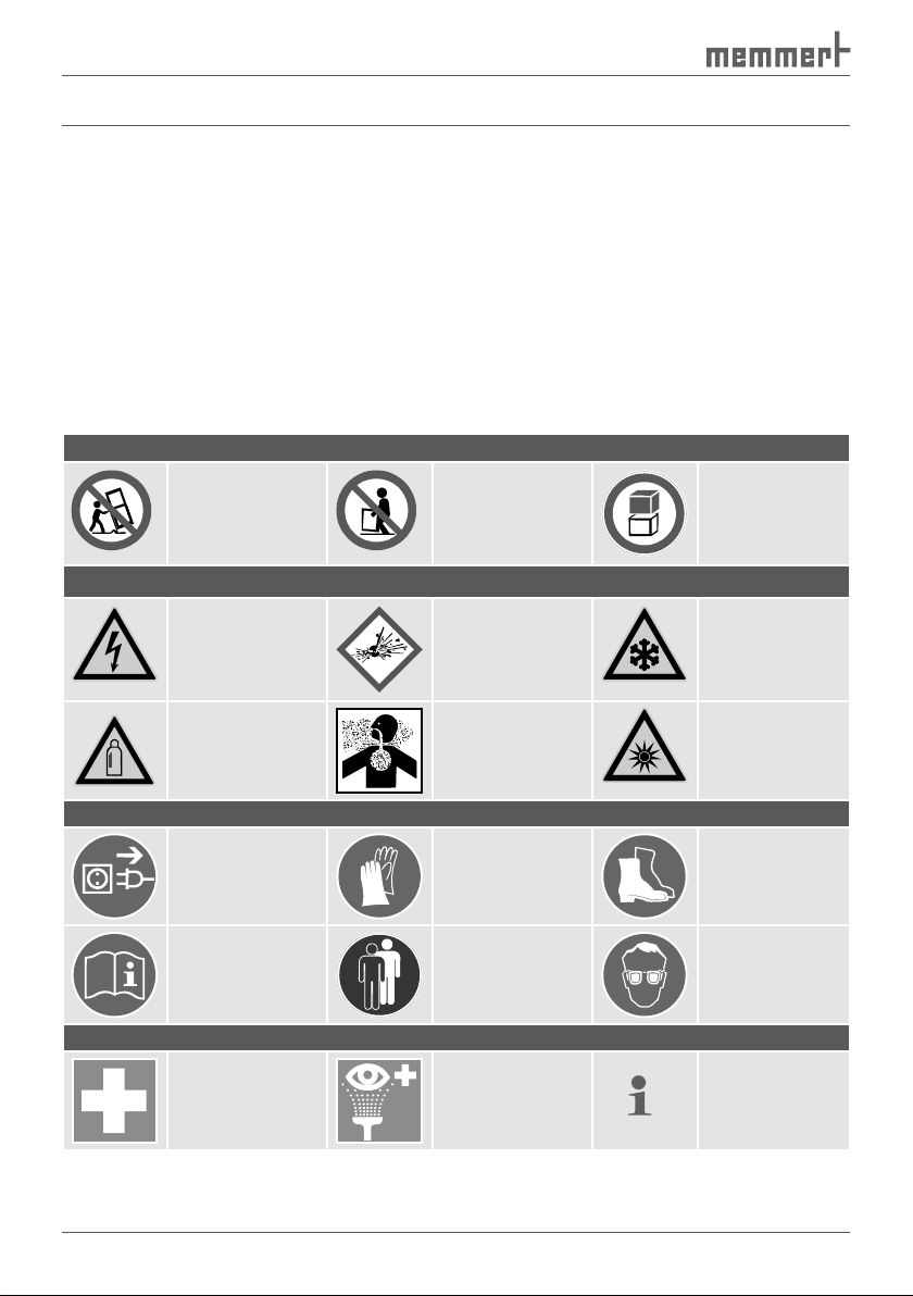
Terms and signs used
and regulations to avoid accidents and damage. These terms and signs are explained below.
Terms used
"Warning"
"Caution"
Prohibition sign (forbidding an action)
appliance
appliance
appliance
atmosphere
frostbite/cold
Warning of gas
Wear gloves
Wear safety
Two or more
Wear UV safety
first aid
additional
Warning signs (warning of a danger)
Regulation signs (stipulate an action)
Other icons
Page 7
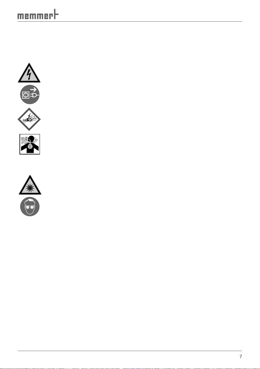
and subject to many hours of testing in the factory. They contain the latest technology and
Warning!
After removing covers, live parts may be exposed. You may receive
an electric shock if you touch these parts. Disconnect the mains plug
Any work inside the unit may only be performed by qualified electri-
cians.
Warning!
When loading the chamber with an unsuitable load, poisonous or
explosive vapours or gases may be produced. This could cause the
chamber to explode, and people could be badly injured or poisoned.
The chamber may only be loaded with materials/test objects which
on page
).
Additional safety regulations for cooled incubators with interior UV
Warning!
when you open the door of the cooled incubator with interior UV
).
Page 8
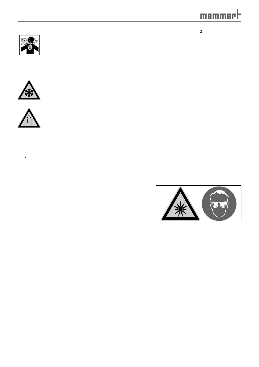
Additional safety regulations for cooled incubators with CO
2
supply.
Warning!
can have a suffocating effect in high
concentrations. In normal operation, the cooled incubator gives
off small amounts of CO
2
to its surroundings. You should therefore
ensure that the room in which it is installed is properly ventilated.
Always close the stop valve or pressure reducer on the gas bottle if
there is no gas bottle connected or if the bottle connected is empty.
Warning!
can cause cold burns or frostbite.
Avoid contact with CO
gas to the eyes and skin.
Warning!
water from penetrating as well as backflow into the gas bottles. It is
essential that you read the safety notes and regulations of the gas
2
is not a dangerous substance in terms of the German Hazardous Substances Ordinance
Warning signs for dangerous UV radiation in the working
area are attached to the doors or cooled incubators
with interior UV lighting (
). They indicate that
UV
These stickers must not be removed and must always
from Memmert customer service.
The cooled incubator may only be operated and maintained by persons who are of legal age,
and who have received relevant instructions. Personnel who are to be trained, instructed or
who are undergoing general training may only work with the appliance under the continuous
The cooled incubator may only be transported (with a forklift truck or manual pallet jack)
Fig. 1
Warning sign on the door
Page 9

The owner of the cooled incubator
and for its proper
);
are qualified to do this, have received the respective instructions and are familiar with this
and repair work is properly carried out;
and its surroundings are kept clean and tidy;
safety goggles, safety shoes, protective gloves.
)
The manufacturer is not liable for any damage, danger or injuries that result from
The cooled incubator may only be used in a flawless condition. If you as the operator notice
and inform your superiors.
You can find information on eliminating malfunctions from page
47
.
Page 10
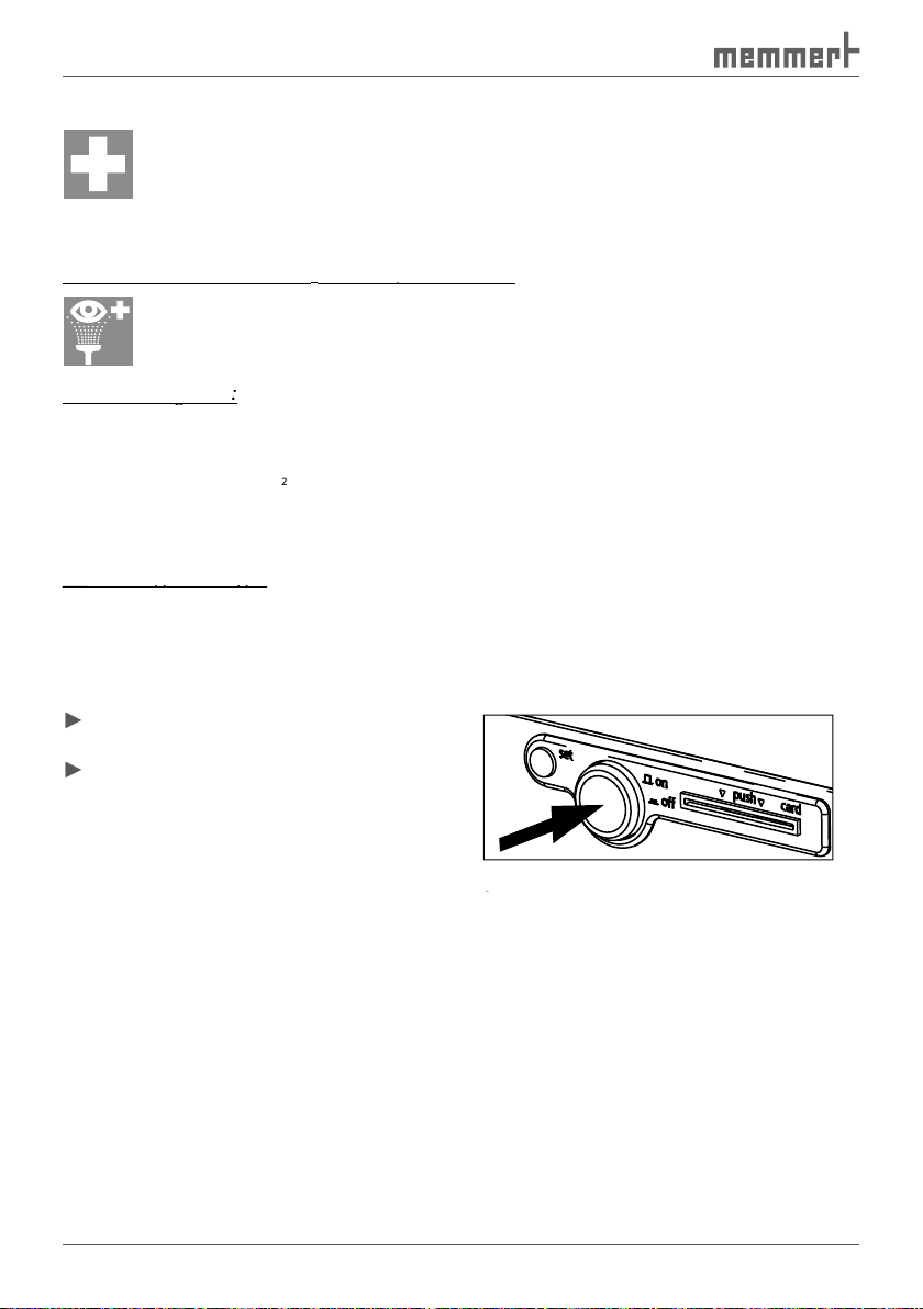
What to do in case of
4.
In case of contact with CO
to the eyes and skin:
to the eyes and skin:
After inhaling CO
After inhaling CO
2
2
can cause accelerated breathing and headaches.
Anyone affected should breathe fresh air, using a breathing device independent of
In
case of gas leakage:
case of gas leakage:
atmosphere is harmless.
Switching off the cooled incubator in an
appliance (
).
Fig. 2
Switch off the cooled incubator
by pressing the main switch
Fig. 2
Fig. 2
Page 11
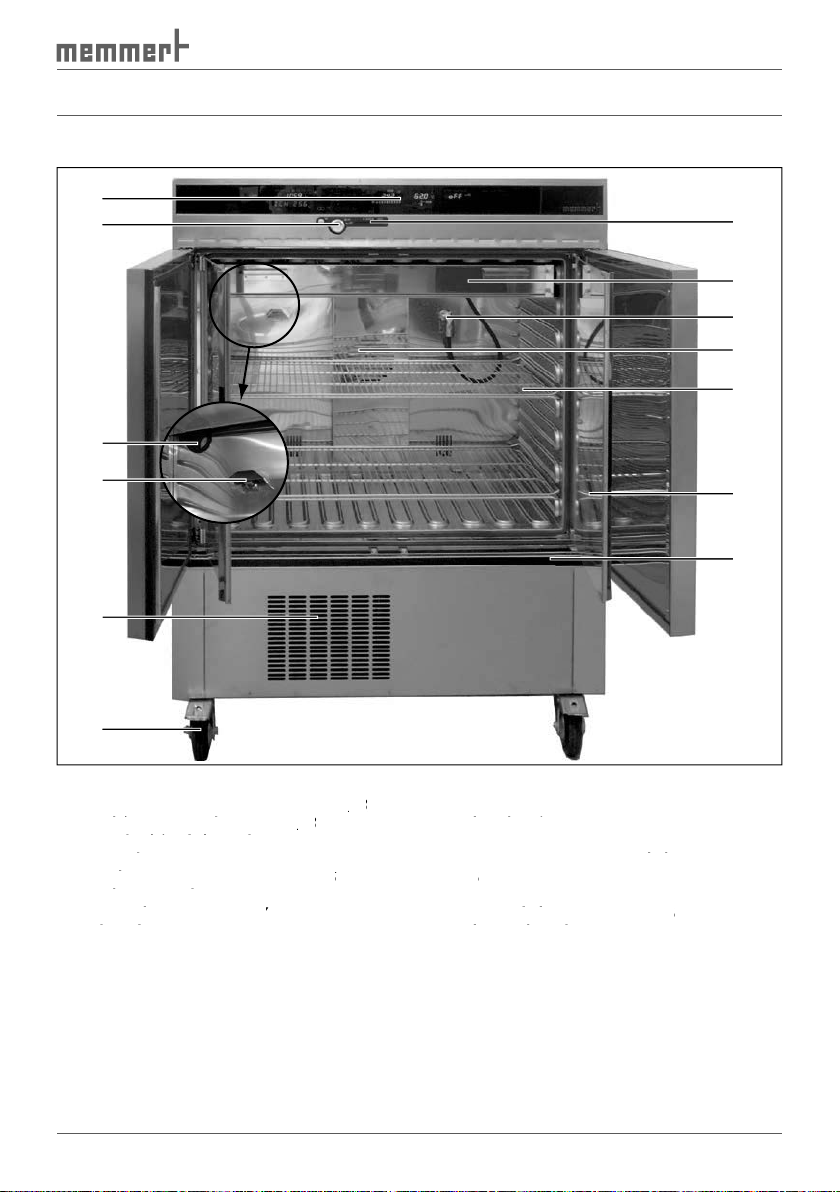
Design and Function
1
Fig. 3
Design of ICH cooled incubators
Controller/control panel (see page
28
)
2
Push/turn control (see page
Controller/control panel (see page
Controller/control panel (see page
28
)
3
Standard feed-through
Push/turn control (see page
Push/turn control (see page
Humidity sensor
Standard feed-through
Standard feed-through
5
Cooling compressor (see page
Humidity sensor
Humidity sensor
65 )6
Locking swivel castors
Cooling compressor (see page
Cooling compressor (see page
Nameplate (see page
Locking swivel castors
Locking swivel castors
)
8
Glass door
Nameplate (see page
Nameplate (see page
9
Sliding grid
Chamber fan
Sliding grid
Sliding grid
Connection for the
illumination box (only
for models with interior lighting, see page
illumination box (only
illumination box (only
66
)
Illumination box (only for models with
interior lighting, see page
Illumination box (only for models with
Illumination box (only for models with
66
)
Chipcard reader
interior lighting, see page
interior lighting, see page
Air is heated inside the cooled incubator by means of large-area all-round heating. Humidifica-
tion
is achieved by
fan and mixed with the air current. Humidity is reduced by condensing on two Peltier cooling
automatically defrosted in cycles.
2
13
12
11
10
9
3
4
8
7
5
6
Page 12
2
supply,
through a sterile filter. The turbulence-free interior ventilation ensures a uniform gas distri-
2
content is reduced by introducing
fresh air.
at the top of the interior (see
on page
) that contains fluorescent tubes (daylight
rh without light max.
rh without light max.
rh without light min.
Intermediate test zone II 30
°
C/65%rh
Long term test zone I 21
°
C/45%
Long term test zone II 25
°
C/60%rh
Long term test zone IVA 30
°
C/65%rh
rh without light max.
rh without light min.
Intermediate test zone II 30
°
C/65%rh
Long term test zone I 21
°
C/45%
Long term test zone II 25
°
C/60%rh
Long term test zone IVA 30
°
C/65%rh
Long term test zone IVB 30
°
C/75%rh
Alternate accelerated test 40
°
C/75%rh
Alternate intermediate test 30
°
C/35%rh
0 10203040506070
rh without light max.
rh without light min.
Intermediate test zone II 30
°
C/65%rh
Long term test zone I 21
°
C/45%
Long term test zone II 25
°
C/60%rh
Long term test zone IVA 30
°
C/65%rh
Long term test zone IVB 30
°
C/75%rh
Alternate accelerated test 40
°
C/75%rh
Alternate intermediate test 30
°
C/35%rh
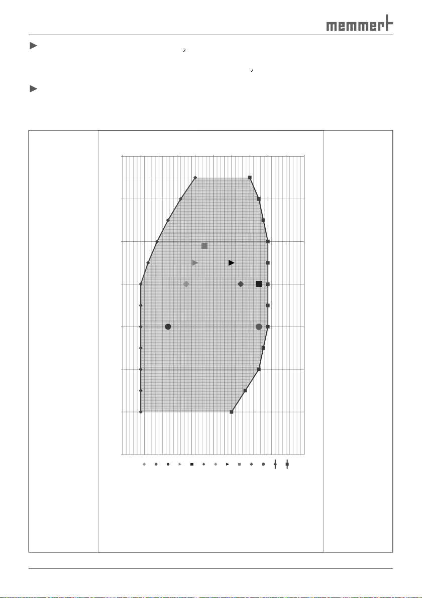
Fig. 4
relative humidity [%]
relative humidity [%]
50
60
70
10
20
30
40
50
10
20
30
0
temperature[C°]
40
60
50
60
80
70
80
70
80
100
100
100
100
90
90
90
90
Working range relative humidity without condensation ICH256
Working range relative humidity without condensation ICH256
Working range relative humidity without condensation ICH256
Working range relative humidity without condensation ICH256
Testing conditions according to ICH Q1A
Testing conditions according to ICH Q1A
Testing conditions according to ICH Q1A
Testing conditions according to ICH Q1A
Long term test zone II 30°C/35%rh
Alternate long term test 25°C/40%rh
Alternate accelerated test 40°C/25%rh
Alternate long term test 25°C/40%rh
Alternate accelerated test 40°C/25%rh
Long term test zone II 30°C/35%rh
Long term test zone II 30°C/35%rh
Accelerated test 40°C/75%rh
Accelerated test 40°C/75%rh
Accelerated test 40°C/75%rh
valid at T
amb
~20°C
Page 13

All-round large-area heating with additional thermal conduction layer
Alphanumeric text display
Two separate Pt100 temperature sensors DIN class A in a 4-wire circuit for control and
following (ASF)
Visual alarm indication
Acoustic warning signal
at the appliance, without the
Additional fittings
The ICH 256 cooled incubator can be equipped with the following fittings:
2
supply
The chamber load for the appliance must be carefully checked for chemical compatibility with
the materials mentioned.
A material resistance table can be requested from the manufacturer.
Page 14

)
Appliance fuse: Fusible link 250 V/15 A quick-blow
The temperature controller is protected with a miniature fuse 100 mA (200 mA at 115 V)
The CO
controller is equipped with a 6.3 A miniature fuse.
1
Fig. 5
Connections on rear of appliance
Mains lead
Connections on rear of appliance
Connections on rear of appliance
2
CO
connection (only for models with CO
supply)
3
2
2
connection (only for models with CO
connection (only for models with CO
ethernet connection, see page
2
2
supply)
supply)
57
)
4
Printer connection (see page
51 )5
23
)
6
Fresh air connection (only for models with CO
2
supply)
with residual current circuit breaker).
This appliance is intended for operation on an electrical power system with a system imped-
ance Z
of a maximum of 0.292 ohm at the point of transfer (service line). The operator
the system impedance is.
3
4
CO
2
2
5
6
Page 15

2
supply)
The appliance can be connected with the supplied
tor with gas bottle monitor (DIN 8546) to a CO
2
compressed gas bottle or directly to a central
gas supply.
The
Water connection
The supplied tube can be used to connect the cooled incubator with the supplied water tank.
tests or similar. Any other use is improper, and may result in hazards and damage.
The incubators may not be used for drying, vaporising and branding paints or similar materi-
als the solvents of which could form an explosive mixture when combined with air. If there
2
gas bottles with a pressure regulator may be connected to the gas connection of the
appliance. The use of other gases or materials than CO
2
is not permitted.
Page 16
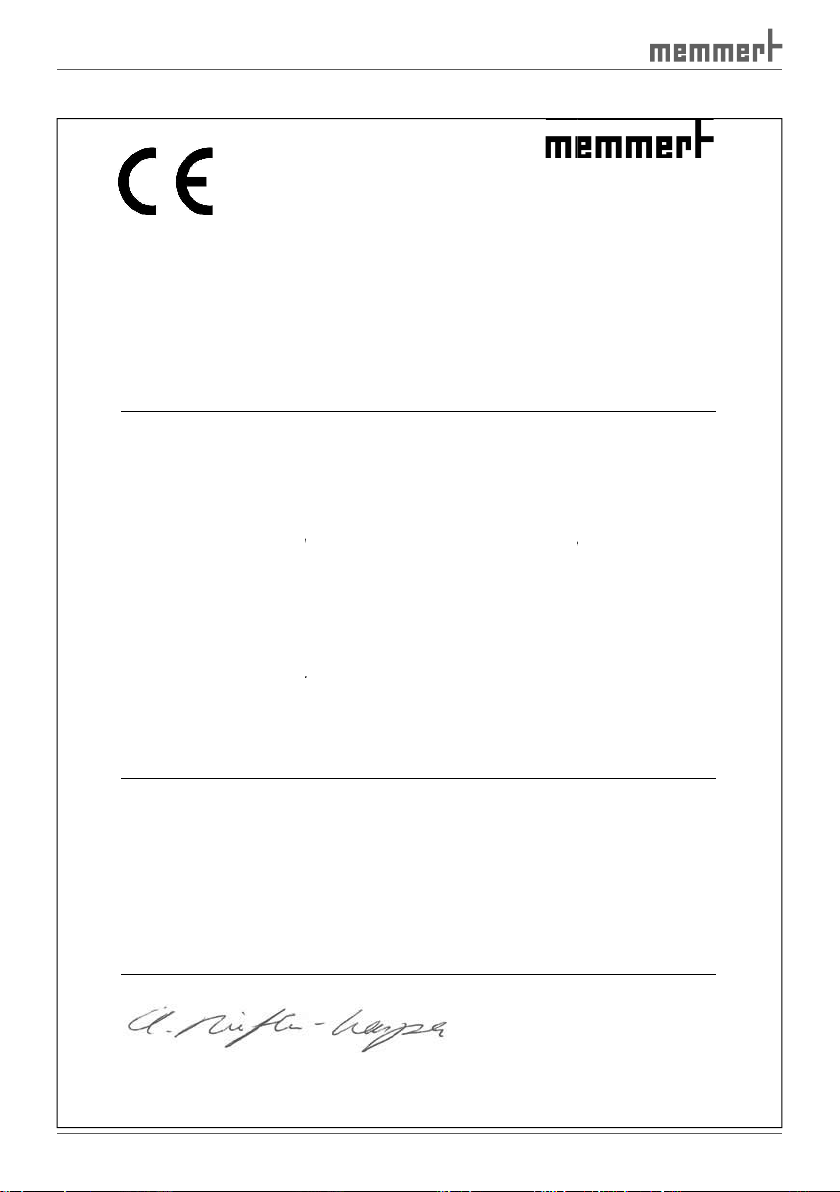
EC Declaration of Conformity
Manufacturer’s name and address:
This product complies with the provisions of the
Machinery Directive 2006/42/EC
Directive of the Council for harmonisation of
The tested product’s level of compliance with the essential protection requirements of the Directive is substantiated
by its compliance with the following standards:
EMC Directive 2004/108/EC
ouncil for harmonisation of the laws of
level of compliance with the essential protection requirements of the Directive is substantiated
by its compliance with the following standards:
Low Voltage Directive 2006/95/EC
ouncil for harmonisation of the laws of
equipment designed for use within certain voltage limits.
compliance with the essential protection requirements of the Directive is substantiated
by its compliance with the following standards:
1 (VDE 0411 part 1):2002
-
(legally binding signature of the manufacturer)
compliance
documents have to be observed.
MEMMERT GmbH + Co. KG
Äußere Rittersbacher Straße 38
, Germany
alternativ
the laws of Member States on the level of protection
EMC Directive 2004/108/EC
tates on electromagnetic
11: 2000
tates relating to electrical
010:2003
irectives, however, does not provide any warranted properties. The
D24249
Product:
Type:
Size:
Rated voltage:
EN ICO 12100-1, -2: 2004
EN ISO 13850: 2007
Directive of the C
The tested product’s
DIN EN 61326-1: 2006-10
DIN EN 61000-3-11: 2001-04
Applied harmonised standards:
Directive of the C
The tested product’s level of
DIN EN 61 010DIN EN 61 010-2-010 (VDE 0411 part 2
Schwabach, Germany, 09/02/2011
This declaration states the
safety instructions in the supplied
91126 Schwabach
Cooled incubator
ICH
256
AC 230 V,
directives:
and revisions
for accident prevention.
EN ISO 13857: 2008
EN 60204-1: 2007
and revisions
compatibility.
Member S
EN 61000-3-
and revisions
-08 EN 61 010-1:2001
010):2004-06 EN 61 010-2-
with the above D
EN 61326-1: 2006
Member S
ely AC 115 V 50/60 Hz
Page 17
Designation
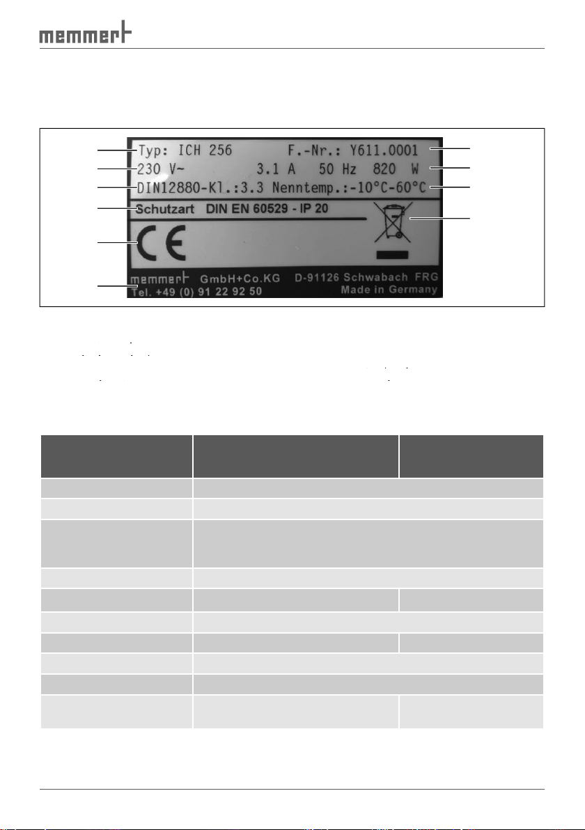
The nameplate (
) provides information about the appliance model, manufacturer and
technical data. It is attached to the front of the appliance, on the right beneath the door (see
1
Fig. 6
Nameplate
Operating voltage
3
Applied standard
Operating voltage
Operating voltage
Protection type
5
CE conformity
Protection type
Protection type
6
Address of manufacturer
Disposal note
8
9
Connection/performance values
Factory number
Connection/performance values
Connection/performance values
Technical data
Appliance width D* [mm]
Appliance height E* [mm]
Appliance depth F*
Weight [kg]
on page
2
3
4
10
9
8
7
5
6
Technical data without interior
lighting
with interior
lighting
Page 18
Technical data without interior
Temperature
Temperature recording is done by means of Pt100 in a 4-wire
Adjustment range normal operation: -10 °C to 60 °C, for mod-
2
supply or interior lighting 0 °C to 60 °C
Adjustment precision: 0.1 °C
Adjustment range: 10 to 80 % rh
Adjustment precision: 1 % rh
The CO
content is determined
through an NDIR measuring pro-
ally in percent
Adjustment range: 0 to 20 %
Adjustment precision: 0.1 %
lighting
with interior
lighting
Page 19
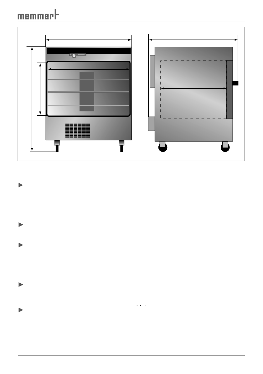
D
Fig. 7
Dimensions of ICH cooled incubators
Ambient conditions
The cooled incubator may only be used in enclosed rooms and under the following ambient
Ambient temperature: 5 ºC to 28 ºC
Altitude of installation: max. 2000 m above sea level
The cooled incubator may not be used in areas where there is a risk of explosions. The
ambient air must not contain any explosive dusts, gases, vapours or gas-air mixtures. The
age to electrical parts. For this reason, sufficient measures are to be taken to prevent large
Accessories
Water supply tank and connection tube
Additional for cooled incubators with CO
2
supply:
supply:
A
F
B
E
C
►
Page 20

Transport and
Warning!
You may injure your hands or feet when transporting and
gloves and work shoes.
Warning!
for this (e.g. forklift truck licence). The cooled incubator may not be
transported with a crane.
Warning!
The cooled incubator could fall over and seriously injure you. Never
tilt the cooled incubator and transport it only in an upright position.
Warning!
Warning!
The cooled incubator may only be set up on the floor, and never on
tables or similar. A table could collapse or the appliance could fall
off and seriously injure or kill
Transport
The cooled incubator can be transported in three ways:
with
a forklift truck; move the forks of the truck entirely under the test chamber
Page 21

The cooled incubator is delivered in cardboard packaging on a pallet.
from the delivery note, damage or irregularities, do not put the cooled incubator into
protective foil) in accordance with the legally
applicable disposal regulations for cardboard packaging in your country.
Page 22
The cooled incubator may only be placed on the ground, not on a table. When doing this,
The installation site must be level
and must be able to reliably carry the weight of the cooled incubator (see page
). Do not
The front swivel castors can be locked with a catch. To ensure stability, always turn the front
A
) must
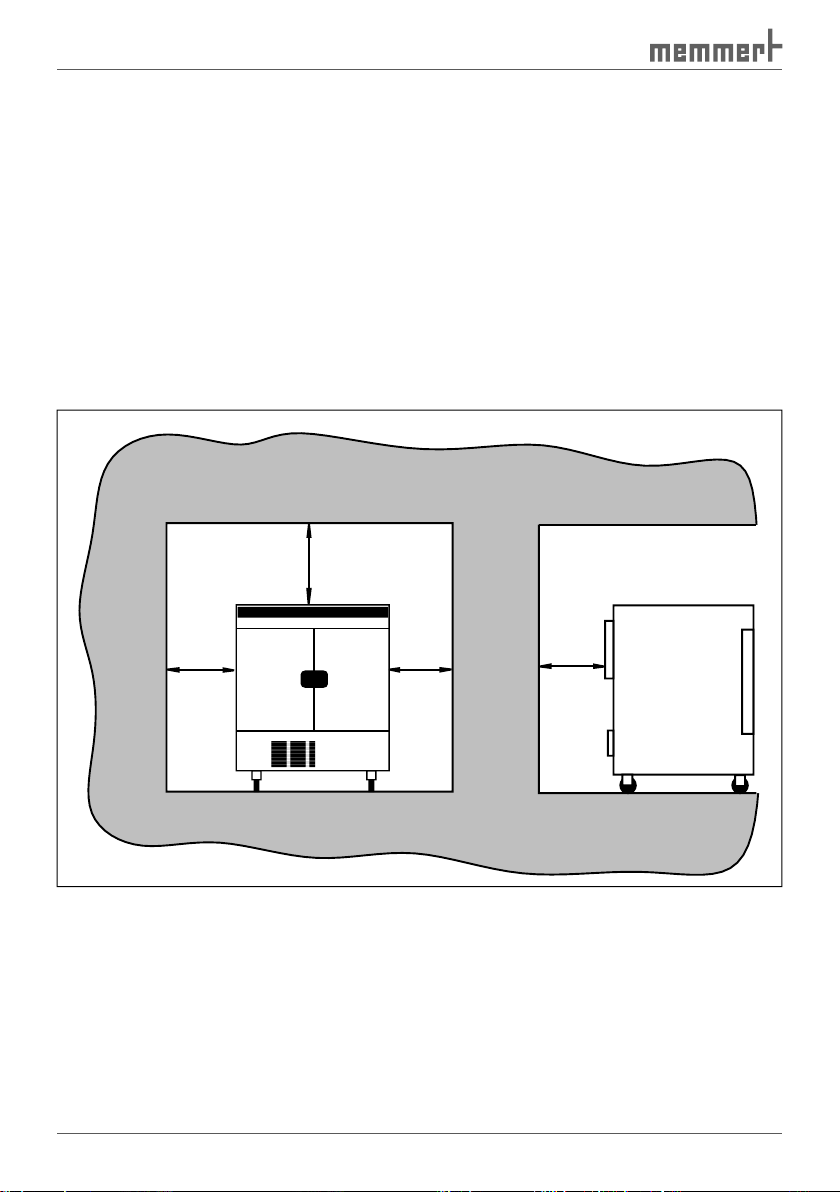
The distance between the wall and the rear of the cooled incubator must be at least 15 cm.
The clearance from the ceiling must not be less than 20 cm and the side clearance from the
wall must not be less than 8 cm (
). The ventilation slits of the
on the rear of
the appliance may not be adjusted.
Fig. 8
Minimum clearance from walls and ceiling
≥ 20 cm
.
≥ 8 cm
≥ 8 cm
≥ 15 cm
Page 23

4.1
.
4.2
4.2.1
The cooled incubator is intended for operation on an electrical power system with a
max
at the point of transfer (service line) of a maximum of 0.292 ohms. The op-
that meets these requirements.
on page
).
) whose interfaces comply with the requirements for safety extra-low voltage (e.g.
4.2.3
Water connection
2
).
aqua dest)
accordance with VDE 0510/DIN EN
adhered to (production conductivity ≤
with VDE 0510 is available in larger
trade. The standard VDE 0510/DIN EN
the label.
Fig. 9
Water connection
H2O
Page 24

4.2.4
Gas connection
supply)
Warning!
can have a suffocating effect in high
concentrations. In normal operation, the cooled incubator gives
off small amounts of CO
to its surroundings. You should therefore
ensure that the room in which it is installed is properly ventilated.
Warning!
can cause cold burns or frostbite. Avoid
contact with CO
gas to the eyes and skin.
Warning!
gas bottles away from open flames. Store gas bottles at lower than
as well as backflow into the gas bottles. It is essential that you read
the safety notes and regulations of the gas suppliers.
Attach the supplied pressure tube to the gas
2
and page
).
CO
Fig. 10
CO2 connection
2
Page 25

Warning!
when opening the door of the cooled incubator with interior UV
).
The cooled incubator may only be operated and by persons who are of legal age and have re-
To open the doors, pull out the knobs (
).
To close, press in the door knobs.
Switching on appliance
The cooled incubator is switched on and off by pressing the
).
).
Fig. 12
Switch on cooled incubator
Fig. 13
Switch off cooled incubator
close
Fig. 11
Opening and clos-
ing the doors
open
Page 26

As the
fluorescent
tubes prior to every test.
equipped with UV lighting: Wear
)
fluorescent tubes are working. If not: Replace the respective tube set (refer to
)
4.
and reading off the measured illuminance. Replace the fluorescent tubes if the light
).
Loading the cooled incubator
Warning!
When loading the appliance with an unsuitable load, poisonous or
explosive vapours or gases may be produced. This could cause the
cooled incubator to explode, and people could be seriously injured
or poisoned. The chamber may only be loaded with materials which
which cannot ignite. If there is any doubt as to the composition of
the chamber load for chemical compatibility with the materials of the cooled
), since considerable damage could otherwise occur to the
The cooled incubator is
explosion-proof (it does not comply with the German workplace
when combined with air. Potentially explosive gas-air mixtures must not form, neither in the
ance could lead to sedimentation in the chamber interior and as a consequence, could result
taken to prevent large clouds of dust or aggressive vapours from developing.
Page 27

The chamber must not be loaded too tightly, so that proper
air circulation in the working
walls or right below the ceiling (heating ribs) of the working chamber. To guarantee optimum
air circulation, push in the sliding grids so that the gaps between the door, sliding grid and
Fig. 14
Correct and incorrect chamber loading
Connecting gas supply
supply)
).
Page 28

The desired parameters are entered on the operating panel of the controller on the front of
the appliance (
). Basic settings, as well as those for time and pressure, can also be made
1
Fig. 15
Operating panel
2
Operating mode display (see page
29
)
3
Display appliance is heating up
Operating mode display (see page
Operating mode display (see page
4
5
Display: appliance is cooling down
6
Alarm display (see chapter
Display: appliance is cooling down
Display: appliance is cooling down
)
chapter
)
8
Humidity display
chapter
chapter
9
Setting the CO
Humidity display
Humidity display
setpoint (only for models
with CO
Setting the CO
Setting the CO
2
supply)
2
2
setpoint (only for models
setpoint (only for models
Display: appliance is humidifying
Display: water tank empty
Display: appliance is humidifying
Display: appliance is humidifying
Display: fan speed
Display: water tank empty
Display: water tank empty
Card reader
Display: fan speed
Display: fan speed
Push/turn control
Set key
rior lighting) Display: interior lighting
All operating functions are selected by turning the push-turn control to the
Tu
Mo
on
off
Sa Su
Fr
Th
We
h
2 3 4 5 6 7 8 9
t3
t2
t1
set
t4
loop
SETUP
PRINT
on
off
STERI DEFRO
4
3
2
1
push
°C
MIN
AUTO
card
IN 1
OUT
IN 2
IN 1
OUT
°C
MAX
IN 2
%
mb
IN 1
OUT
IN 2
OUT
2
2
rh
CO
mb
10111213141516
set
set
Page 29

temperature), then all other parameters go dark and the selected one flashes.
With the SET key held down, set the desired value (e. g.
37.0
) with the
value, flashing. Then, the current temperature is displayed and the cooled
The control returns automatically to the main menu if neither the push-turn control
Quick adjustment of temperature:
Quick adjustment of temperature:
The appliance flashes briefly, displaying the temperature setpoint. Then, the current tempera-
ture appears on the display and the controller begins to adjust the temperature to the set
value.
):
Week time switch: The cooled incubator runs at the set values only at certain times. Opera-
tion in this mode is described from page
.
or lighting
values are programmed (so-called ramps), which the cooled incubator automatically works
through one after another. Operation in this mode is described from page
).
) and printouts (PRINT, see page
)
)
Week
time switch
) ) )
Fig. 16
Operating modes
set
set
set
PRINT
SETUP
Page 30

Setting the operating mode
Normal mode
values for operating the appliance can be selected. The settings have an immediate effect on
the functions of the appliance.
).
that it comes out of the appliance (see
on page
).
with the push-turn control as described
above.
As described above, set the individual parameters with the push-turn control and the SET
Adjustment range:
to
for models
without CO
supply and without interior
-10°C
to
Adjustment range: 10 % to 100 % in steps
Temperature monitoring
Temperature monitoring
Adjustment range:
)
Adjustment range:
to
%rh
%
rh
setpoint
setpoint
Adjustment range:
to
%
CO
set
set
set
SETUP
PRINT
°C
°C
MIN
MAX
AUTO
2
Page 31
UV light
UV light
Adjustment range:
Adjustment range:
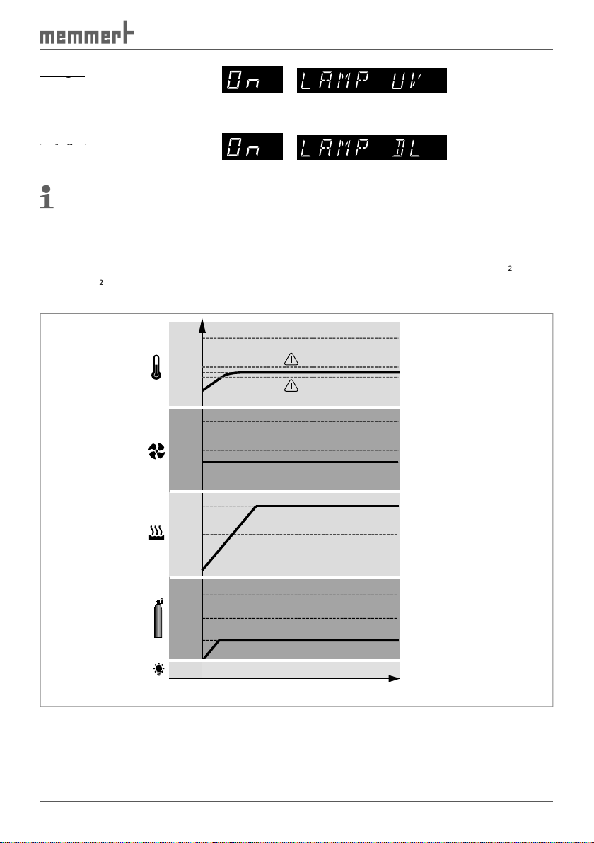
The appliance should heat up to 37 °C with a humidity of 80 % rh and a fan speed of 40 %.
The monitoring function should trigger at 38.5 °C and at 36.0 °C: For a model with CO
2
sup-
2
content should be 5.0 %. For a model with interior lighting, daylight should be
Fig. 17
Example for normal mode
50 °C
37 °C
80 %
50 %
40 %
80 %
rh
50 %
rh
15 %
10 %
5 %
DL
t
Page 32

with the push-turn
vated.
37.0
°C with the push-turn control.
temperature appears on the display and the control-
symbol.
icon.
Turn the push-turn control to the right, up to the moni-
toring temperature and until the MIN or MAX symbol
flashes. Hold down the SET key and, with the push-turn
°C and the
°C. Turn the push-turn
the AUTO symbol flash. Hold down the SET key and, with
the push-turn control, select
The tolerance band is set in the SETUP menu (see
).
4.
Turn the push-turn control to the right until the humid-
% rh with the push-turn
The humidification process is indicated by the
PRINT
SETUP
°C
°C
MIN
MAX
AUTO
%rh
Page 33

2
setpoint
2
supply)
Turn the push-turn control to the right until the CO2 dis-
the CO2 setpoint. The current CO2 actual value appears
CO
Adjust lighting
Turn the push-turn control to the right until
with the push-turn control. Release
the SET key. The daylight lighting is activated.
The cooled incubator is now running in permanent operation with the set values.
Week time switch
and cooling functions, along with the CO
2
and humidity supply are switched off here and the
The sequence of the week time switch repeats itself each week.
Weekday
Weekday
Adjustment range: Monday to Sunday
Mo
Adjustment range: Working days Mo-Fr
Weekend Sat-Sun
----
Appliance not switched on on this day
Adjustment range:
to
23:59
h
Adjustment range: one minute after the switch-
h
Tu
We
Th
2
SETUP
PRINT
Sa
Su
Fr
Mo
Mo
on
off
on
off
on
off
Tu
Tu
We
We
Th
Th
Sa
Sa
Su
Su
Fr
Fr
Page 34

the desired time blocks and days.
ture setpoint can be directly accessed by briefly pressing the SET key. By turning the control
to the right, you get to the temperature monitoring, humidity and CO
2
settings. By turning to
the left, you can return to the settings for the individual time blocks.
The appliance should switch on from Mo-Fr (workdays group) at 9.30 (am) and switch off at
).
Fr
Fig. 18
Operation with week time switch (example)
week time switch operating mode
with the push-
turn control, while the SET key is held down.
time switch operating mode.
Sa
PRINT
Tu
We
Mo
Th
Su
SETUP
Page 35

Turning the push-turn control to the left, select "
time with the push-turn switch to
(am).
Mo
turn control.
time with the push-turn switch to
With the push-turn control, select "
time with the push-turn switch to
With the push-turn control, select "
time with the push-turn switch to
).
Programme mode
2
or
automatically one after another.
Setting the programme operating mode
Setting the programme operating mode
with the push-turn
function with the push-turn.
function with the push-turn.
on
off
Tu
We
Th
Fr
Sa Su
Mo
Mo
Mo
on
off
Tu
Tu
on
off
Tu
on
off
We
We
We
Th
Th
Th
Fr
Fr
Fr
PRINT
Sa Su
Sa
h
Sa
h
Su
Su
SETUP
PRINT
SETUP
Page 36
You can now select and modify the following parameters in turn (see also the adjustment
):
STERI
4.
Adjustment range: Monday to Sunday, workdays Mo-Fr, weekends Sa-Sun, every day Mon-Sun
) after the start
Sa
Adjustment range:
to
(shown: Switch-on time
)
Th
Sa
Adjustment range:
to
999
hours. In the example shown: Duration of first ramp seg-
DEFRO
Adjustment range:
Tu
Mo
on
off
Sa Su
Fr
Th
We
t1
h
t3
t2
PRINT
4
t4
3
loop
2
1
SETUP
DEFRO
°C
MAX
MIN
AUTO
IN 1
OUT
IN 2
°C
%rh
mb
STERI
DEFRO
STERI
DEFRO
°C
MAX
MIN
AUTO
DEFRO
MAX
MIN
AUTO
°C
MAX
MIN
AUTO
Tu
Mo
on
off
Tu
Mo
on
off
Tu
Mo
on
off
Sa Su
Fr
Th
We
t1
h
Sa Su
Fr
Th
We
t1
h
Sa Su
Fr
Th
We
t1
h
t3
t2
PRINT
t3
t2
PRINT
t3
t2
PRINT
4
t4
3
loop
2
1
SETUP
4
t4
3
loop
2
1
SETUP
STERI
4
t4
3
loop
2
1
SETUP
IN 1
OUT
IN 2
°C
IN 1
°C
%rh
mb
OUT
IN 2
mb
°C
Page 37

STERI
Adjustment range: 10 % to 100 % in 10-% steps In the example shown: fan speed 60 % (six
Adjustment range:
to
80 % rh
and
OFF
2
content of first ramp segment
content of first ramp segment
2
supply)
Adjustment range:
to
20 %
2
content 5.0 %.
Adjustment range:
Tu
Mo
on
off
Tu
Mo
on
off
Tu
Mo
on
off
Sa Su
Fr
Th
We
t1
h
Sa Su
Fr
Th
We
t1
h
Sa Su
Fr
Th
We
t1
h
t3
t2
t2
t2
t4
loop
SETUP
PRINT
t3
t4
loop
SETUP
PRINT
t3
t4
loop
SETUP
PRINT
4
3
2
1
STERI
4
3
2
1
STERI
4
3
2
1
DEFRO
DEFRO
DEFRO
°C
MIN
°C
MIN
°C
MIN
AUTO
AUTO
AUTO
°C
MAX
%rh
°C
mb
MAX
%rh
°C
mb
MAX
CO
2
STERI
Tu
Mo
on
off
Sa Su
Fr
Th
We
t1
h
t3
PRINT
t4
loop
SETUP
t2
DEFRO
4
3
2
1
°C
MIN
AUTO
%rh
°C
mb
MAX
CO
2
Page 38

STERI
Adjustment range:
These commands thus control the programme sequence:
ter
"
" on page
).
Turn the push-turn control to the right until
appears the display and then press the SET
After releasing the SET key ...
as described above, or an existing
Tu
Mo
on
off
Tu
Mo
on
off
Tu
Mo
on
off
Sa Su
Fr
Th
We
t1
h
Sa Su
Fr
Th
We
t1
h
Sa Su
Fr
Th
We
t1
h
t3
t2
t2
t2
t4
loop
SETUP
PRINT
t3
t4
loop
SETUP
PRINT
t3
t4
loop
SETUP
PRINT
4
3
2
1
STERI
4
3
2
1
STERI
4
3
2
1
DEFRO
DEFRO
DEFRO
AUTO
AUTO
AUTO
%rh
°C
mb
MAX
%rh
°C
mb
MAX
%rh
°C
mb
MAX
°C
MIN
°C
MIN
°C
MIN
CO
CO
CO
2
2
2
Page 39

Close statements for
These commands thus control the programme sequence:
Wait until the setpoint temperature has been reached.
The appliance starts the next programme segment only when the
Wait until setpoint humidity has been reached.
Appliance starts the next programme segment only when the
time has already elapsed.
)
Wait until setpoint temperature and setpoint humidity have been
when the programmed setpoint temperature and programmed
already elapsed.
The programme entered is repeated after it has run through all
°C
t=time
Close
Fig. 19
Schematic example of the use of ramp segment close statements
Delayed
programme start
Close
command
ramp
segment
No. 1
spwt (t)
Segment1
command
segment
Segment2
Close
ramp
No. 2
next
Close
command
ramp
segment
No. 3
spwt (tH)
Segment3
Segment4
command
ramp
segment
No. 4
next
command
Segment5
Close
ramp
segment
No. 5
end
Page 40

40
a fan speed of 30 %, and reach a relative humidity of 70 % rh. For models with CO
supply,
the CO
2
content should be set to 5 % and for models with interior lighting, daylight should be
the setpoint values at a fan speed of 50 % for 45 minutes. For models with lighting, the test
Afterwards, the appliance should cool down to 20 °C and reach 50 % rh humidity within 1
supply, the CO
content should be adapted to
the natural content of the ambient air and for models with interior lighting, daylight should
50 °C
Fig. 20
Settings example programme mode
Ramp 1 Ramp 2 Ramp 3
no
combination
possible
DL
UV
37 °C
20 °C
80 %
50 %
30 %
70 % rh
50 % rh
15 %
10 %
5 %
overtemperature limit
0.01 h
0.45 h
1.00 h
t
Mo 8.00 h
Page 41

This ramp programme can only be set for cooled incubators equipped with CO
2
supply or
2
or lighting.
The respective descriptions in this example are therefore not relevant for these appli-
ances.
ter, using the "Celsius" software.
while the SET key is held down.
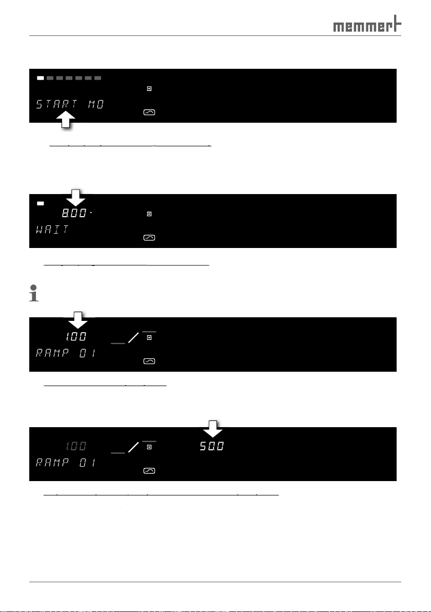
After releasing the SET key, the control is in the pro-
After releasing the SET key, the controller is in the pro-
Weekday for delayed programme start:
by turning the push-turn control
while the SET key is held down.
Mo
with the
Turn the push-turn control further to the right until the
time display flashes.
with the
Turn the push-turn control to the right until the tem-
37.0
with the push-turn control.
°C
PRINT
h
h
SETUP
Page 42

42
Turn the push-turn control to the right until the fan
mb
IN 1
IN 2
OUT
IN 1
IN 2
OUT
°C
°C
MIN
AUTO
MAX
rh
DEFROSTERI
%
Turn the push-turn control to the right until the humidity
70.0 % rh
with the push-turn control.
%
rh
content of the first ramp segment (only
for appliances with CO
supply, otherwise please con-
tinue with point 10):
Turn the push-turn control to the right until the CO
setpoint
to
with the push-turn control.
with lighting, otherwise please continue with item11):
Turn the push-turn control to the left until the
with the push-
turn control.
Turn the push/turn control to the right until a segment
appears.
with the push/turn control.
Turn the push-turn control further to the right until the
time display flashes.
with the
Turn the push-turn control to the right until the tem-
37.0
with the push-turn control.
CO
2
h
°C
Page 43

43
Turn the push-turn control to the right until the fan
Turn the push-turn control to the right until the humid-
70.0 % rh
with the push-turn control.
%
content of the second ramp segment
supply, otherwise please
Turn the push-turn control to the right until the CO
setpoint
to
with the push-turn control.
Turn the push-turn control to the left until the
with the push-
turn control.
Turn the push-turn control to the left until the
with the push-turn
Turn the push-turn control to the right until a segment
with the push/turn control.
Turn the push-turn control to the right until the tem-
with the push-
turn control.
rh
CO
2
h
°C
Page 44

44
Turn the push-turn control to the right until the humidity
with the push-turn control.
%
rh
2
content of the second ramp segment
2
supply, otherwise please
Turn the push-turn control to the right until the CO
2
2
setpoint
to
with the push-turn control.
for models with lighting, otherwise please continue with
Turn the push-turn control to the left until the
with the push-turn
Turn push-turn control to the right until a close state-
and press the SET
Turn push-turn control to the right until
appears in
the display, and press the SET key briefly to confirm.
Turn the push-turn control to the right and adjust the
temperature monitoring (for more detailed information
).
Activating the programme:
Turn the push-turn control to the right until the stop
flashes.
flashes.
with
with
the push-turn control. Release the SET key, and the pro-
Operation with
The cooled incubator can optionally be used, controlled and programmed with a PC/laptop.
and
).
The control of the appliance with the Memmert computer software “Celsius“ is
CO
2
°C
MIN
MAX
Page 45

45
Warning messages during operation: See page
47
.
CO
mode
2
controller is initially deactivated. The CO
2
inlet is interrupted
2
2
gas is introduced into the chamber via a sterile filter. The
Displays in CO
Displays in CO
2
mode:
2
display,
CO
After the setpoint temperature has been reached,
the CO
2
concentration is displayed in % depending
concentration exceeds the
icon flash.
icon flash.
and wait to see if the controller steadily adjusts to
the setpoint. If the error occurs again, contact the
This monitoring function only starts
working once the CO
The pressure in the gas bottles is a constant
approx. 57 bar at 20 °C ambient tempera-
ture. The pressure in the bottle cannot be
2
Page 46

46
Active humidity control
Active humidity control
The active humidity control guarantees that setpoint humidity is quickly reached, without the
after the setpoint temperature is reached, the humidification and dehumidification control
that it clicks into the appliance (
).
supply: Close the
valve on the gas bottle.
Fig. 21
Switch off cooled incubator
Page 47

47
Warning Messages and Malfunctions
Warning Messages and
Warning messages
The warning messages also set off an intermittent acoustic signal:
This can be temporarily switched off by pressing the SET key.
Error in the temperature control system (see also chapter "
Error in the temperature control system (see also chapter "
"
on page
on page
53
):
):
Tb active -
if the
temperature limiter is
triggered
automatic monitoring
function is triggered
ASF temperature monitor.
Error in the dehumidification system:
Error in the dehumidification system:
water supply tank with distilled
water if it is empty.
the setpoint. If the error occurs
again, contact the customer
Error in the CO
system (only for models with CO
system (only for models with CO
2
supply)
supply)
Page 48

48
Warning Messages and Malfunctions
2
supply is defec-
tive
2
setpoint to
the gas bottle is empty, replace
2
setpoint to the
2
concentra-
tion exceeds the defined
the customer service.
System/
Warning!
After removing covers, live parts may be exposed. You may
).
Error Possible cause Remedy
The display
although the
Appliance fuse or
Appliance error
Appliance
with
).
display
module
Page 49

49
Warning Messages and Malfunctions
Error Possible cause Remedy
icon flashes
Temperature protection
triggered
).
... and
Water supply tank empty
water, then reset humidity setpoint back to
... and
the customer service.
... and
2
setpoint is exceeded
the controller steadily adjusts to the setpoint.
... and
Autozero pump
controller defect
Appliance/system error
for only 10 sec.
after switching
when saving setpoint
values)
The error can be rectified by the controller
adapter faulty
Ambient temperature
too high
ambient temperature + 8 °C
Temperature in
appliance higher
than defined setpoint
temperature
Wait until the appliance has cooled down.
symbol is
symbol is
Temperature protection
Page 50
Warning Messages and Malfunctions
In normal
and week time switch operating modes
and week time switch operating modes
After the
The time and duration of the power failure are documented in the
In Programming mode
In Programming mode
After a power failure of less than 60 minutes, the current programme is continued from
the point at which it was interrupted. The time and duration of the power failure are
)
values (see table below).
For remote operation
For remote operation
The programme can only be continued from the computer. The time and duration of the
Parameters Default value
Temperature
Page 51

Advanced Functions
Advanced Functions
The cooled incubator is equipped with a parallel printer port as used in computers. Standard
).
The controller has an internal
). The log data can be printed out in
this mode via the connected printer.
Running the
Running the
printing function:
printing function:
turn control, as described on page 27. By turning
the push-turn control and holding down the SET
as described in chapter
on page
:
PRINT
SETUP
Page 52

Advanced Functions
appliance can be made.
and changed, as described in chapter Basic operation on page 27:
The controller features a calendar that automatically
Weekday
Weekday
Tu
Year
Adjustment range from
to
2100
Acoustic signal at programme end
Acoustic signal at programme end
ON
Acoustic Signal for
Acoustic Signal for
alarm, e.g. over/undertemperature
alarm, e.g. over/undertemperature
ON
Adjustment range:
to
15
“ on page
)
Automatic defrosting system
Automatic defrosting system
).
12h
PRINT SETUP
Page 53

Advanced Functions
Tolerance band ASF
Adjustment range:
to
5°C
)
and
italIANO
for customer-side
2
(see chapter "
" on page
)
The
for logging purposes in accordance with GLP. Date and clock time are specified on the log
Temperature monitoring
The
temperature sensor in the
for the appliance and surroundings.
The appliance is equipped with a double overtemperature protection (mechanical/electronic)
1
Fig. 22
Visual
alarm icon lit up: TB
alarm flashing: TWW
alarm, ASF
alarm
2
alarm icon lit up: TB
alarm icon lit up: TB
alarm flashing: TWW
alarm flashing: TWW
3
Automatic temperature monitor (ASF, see page
56
)
4
Overtemperature protection (TWW, TWB, see page
54 )5
6
Acoustic
alarm icon
1
°C
6
5
2
3
MIN
AUTO
MAX
4
Page 54

Advanced Functions
Mechanical temperature monitoring:
Temperature limiter (TB)
The cooled incubator is equipped with a mechanical temperature limiter (TB) of protection
temperature is exceeded by approx. 20 °C, the temperature limiter, as the final protective
icon lights up.
icon lights up.
Error rectification after the TB has been triggered:
Error rectification after the TB has been triggered:
). Press until you hear a „click“
Temperature monitoring can be adjusted indepen-
The manually set monitoring temperature
MIN
and
and
MAX
the overtemperature control is monitored by an
adjustable over/undertemperature controller (TWW) protection class 3.3 acc. to DIN 12880.
MAX
is exceeded, the TWW takes over
temperature control and begins to regulate the monitoring temperature (
).
The alarm icon flashes as a warning
°C
Fig. 24
Schematic diagram of how the TWW
temperature monitoring works
The monitoring temperature must always be set sufficiently high above the
alarm is switched on in the SETUP, the TWW
alarm is additionally signalled by
an intermittent tone. If the SET key is pressed, the acoustic alarm can be temporarily switched
Fig. 23
TB Reset
Emergency operation
Setting MAX
Set
temperature
Controller error
t
Page 55

Advanced Functions
Setting:
Setting:
Adjustment range: up to max. 10 °C above nominal temperature
MAX
with the push-turn control (e.g. to
38.5
°C)
MIN
Adjustment range: 10 °C below the minimum temperature of
the appliance up to 10 °C above nominal temperature of the
appliance (for details of the nominal temperature, see nameplate).
The lower alarm limit value cannot be set higher than the top
the lowest temperature.
MIN
°C
MAX
AUTO
°C
MAX
AUTO
Page 56

Advanced Functions
Automatic
temperature monitor (
ASF)
ASF is a monitoring device that automatically follows the set temperature setpoint within an
adjustable tolerance band (
).
The ASF is activated – if switched on – automatically if the actual temperature value reaches
first time (section A). The activation of the ASF is shown by the brightly lit
AUTO
icon.
When the temperature violates the set tolerance band around the setpoint (in the example in
: 37 °C ± 3 °C) – e. g. if the door is opened during operation (section B of illustration) –
the
alarm is set off. This is shown by the
AUTO
and
icons flashing.
alarm is switched on in the SETUP, the ASF
alarm is additionally signalled by an
The ASF
alarm is automatically triggered as soon as 50 % of the set tolerance band of the
tolerance range of the new temperature setpoint (section E).
°C
Fig. 25
Schematic diagram of how the ASF temperature monitoring works
Switching on the automatic temperature monitor:
Switching on the automatic temperature monitor:
with the push-turn control.
Switching off the automatic temperature monitor:
Switching off the automatic temperature monitor:
with the push-turn control.
The tolerance band for the ASF can be set in the SETUP
°C (see page
).
37 °C
40 °C
34 °C
A B C D E
40 °C
33 °C
27 °C
ASF active
34 °C
AUTO AUTO AUTO
ASF alarm
ASF active ASF active
MIN
MIN
t
°C
MAX
AUTO
°C
MAX
AUTO
Page 57

Advanced Functions
The cooled incubator is equipped by default with a
on page
). With this interface, it is possible to control and log the
appliance remotely from the computer. This is done with the help of the
To do this, the cooled incubator must be given a unique
). Using this, the respective cooled incubator can be selected and programmed from
the computer. The default setting is
The cooled incubator can optionally be equipped with an
ethernet interface to connect it to
a network. For identification purposes, each cooled incubator connected must have its own
The programme "
XTADMIN", which can be found on the “Celsius“ CD-ROM, can be used to
192.168.1.216
Fig. 26
One or more cooled incubators are connected to a network via
ethernet interface
(schematic diagram)
Fig. 26
Fig. 26
LAN 1: 192.168.1.233
LAN 2: 192.168.1.215
LAN 3: 192.168.1.241
Page 58

Advanced Functions
Log memory
The controller continually logs all relevant measured values, settings and error messages at
The internal
automatically with new data.
The logging function cannot be switched off and is always active. The measured data are
timestamp.
The internal
about three months in permanent operation.
Reading in the log memory to the computer via
Reading in the log memory to the computer via
The log data can be read out either via the
and from there be displayed graphically, printed out and stored.
The
Printing out log memory
Printing out log memory
" on page
)
Automatic defrosting system
The integrated automatic defrosting system for the
the cooled incubator at low temperatures and in permanent operation. The time values for
the automatic defrosting system can be set in the submenu
SETUP
under
under
(see page
).
working chamber. Afterwards, the smooth surface of the interior can easily be cleaned.
Page 59

Advanced Functions
at regular intervals. If you would like to further reduce this detraction in performance, you can
for defrosting, 12 hours, is not sufficient. If this is the case, you should set a more frequent
Automatic defrosting is disabled with the parameter
tures, this causes the cooling unit to ice over over time. Regular defrosting needs to be carried
The device number of the appliance and a
). The
To use it, insert the card into the chip
) on the
appliance control panel.
additional menu item
appears
against all adjustments once the chip
on the control
).
Calibration
Temperature calibration
The cooled incubator can be calibrated customer-specifically using three calibration
temperatures of your choice:
Temperature calibration at low temperature (e.g. 5 °C)
Temperature calibration at medium temperature (e.g. 25 °C)
Temperature calibration at high temperature (e.g. 50 °C)
access
authority
card
Name:
ID:
_____________________
_____________________
Fig. 27
User ID Card
Page 60

Advanced Functions
), a positive or negative compensation correction value
CAL. 3
Default
30°C
20°C
0°
10°C
40°C
Fig. 28
Temperature calibration (example)
Setting:
Setting:
)
and the
accompanying compensation correction value to
°C.
temperature.
temperature is too low, the compensation correction value must be set with a negative
Temperature deviation at 35 °C is to be corrected.
°C
and set the corresponding
°C:
°C
With a calibrated reference instrument and at a defined setpoint temperature of
in
is measured.
calibration
+0,3 °C
CAL. 1
+0,2 °C
CAL. 2
-0,4 °C
h
°C
°C
Page 61

Advanced Functions
- 0.4
°C:
h
°C
After the calibration procedure, the reference instrument should display
With
°C, the factory calibration settings are
The cooled incubator can be calibrated for the individual customer by means of two balance
tive compensation correction value can be set between –5 % and +5 %.
Fig. 29
Humidity calibration (example)
Setting:
Setting:
)
and set the accompany-
With a reference instrument, measure the deviation in the stationary state in the selected
4.
The procedure can be performed with humidity balance points of 20 % rh and 80 % rh.
rh 20
+3,0 %
Default calibration
°C
°C
rh 80
-2,0 %
0%
20%
40%
60%
80% 100%
Page 62

Advanced Functions
and set the accompanying compensation
IN 1
%
With a calibrated reference instrument, an actual humidity of 78 % rh is measured at
.
to
–2.0 %
:
%
IN 2
OUT
4.
After the calibration procedure, the reference instrument should display 80.0 %.
With
a further comparison can be programmed at 20 % relative humidity.
% rh, the factory calibration settings
are restored.
CO
2
calibration
points:
calibration at 5 % CO
content
2
calibration at 10 % CO
2
content
2
calibration at 15 % CO
2
content
Fig. 30
CO
2
calibration (example)
OUT
Tu
Mo
on
off
Tu
Mo
on
off
Sa Su
Fr
Th
We
Sa Su
Fr
Th
We
t3
t2
t1
t2
t1
t4
loop
SETUP
PRINT
t3
t4
loop
SETUP
PRINT
STERI DEFRO
4
3
2
1
4
3
2
1
STERI DEFRO
°C
°C
°C
MAX
MIN
AUTO
°C
MAX
MIN
AUTO
rh
%
mb
OUT
IN 2
rh
%
mb
IN 2
2
CO
mb
IN 1
OUT
IN 2
2
CO
mb
co2 10
Default calibration
+1,5 %
co2 15
-0,7 %
co2 5
-0,4 %
0%
10%
20%
Page 63

Advanced Functions
Setting
Setting
2
balance point in the SETUP (
)
and set the accompanying
With a reference instrument, measure the deviation in the stationary state in the selected
2
balance point.
4.
The procedure can be performed for the CO
2
balance points 5 %, 10 % and 15 %.
2
deviation at 10 % should be corrected:
2
balance point in the SETUP to
and set the accompanying compensation
IN 1
With a calibrated reference instrument and at a defined setpoint CO
2
content of
an
actual CO
2
content of 11.5 % is measured.
to
1.5 %:
The reference instrument should display 10 % after the calibration procedure.
With
and
CO2 15
%
2
calibration
IN 1
OUT
Tu
Mo
on
off
Tu
Mo
on
off
Sa Su
Fr
Th
We
Sa Su
Fr
Th
We
t3
t2
t1
t2
t1
t4
loop
SETUP
PRINT
t3
t4
loop
SETUP
PRINT
STERI DEFRO
4
3
2
1
4
3
2
1
STERI DEFRO
°C
°C
°C
MAX
MIN
AUTO
°C
MAX
MIN
AUTO
IN 2
rh
%
mb
IN 1
OUT
IN 2
rh
%
mb
OUT
IN 2
2
CO
mb
IN 1
OUT
IN 2
2
CO
mb
Page 64
Warning!
out the mains plug.
appearance and functionality of the stainless steel
To clean the interior, the fan cover can be removed by
). The metal surfaces of
the chamber can be cleaned with normal stainless steel
the working chamber or with the stainless steel housing.
working chamber due to impurities, immediately clean
and polish the affected area.
To make cleaning easier, the protective cover can be
).
Fig. 31
To take off the fan
cover, remove two screws
Fig. 32
Cover of the Peltier
cooling modules
Fig. 32
Fig. 32
Page 65

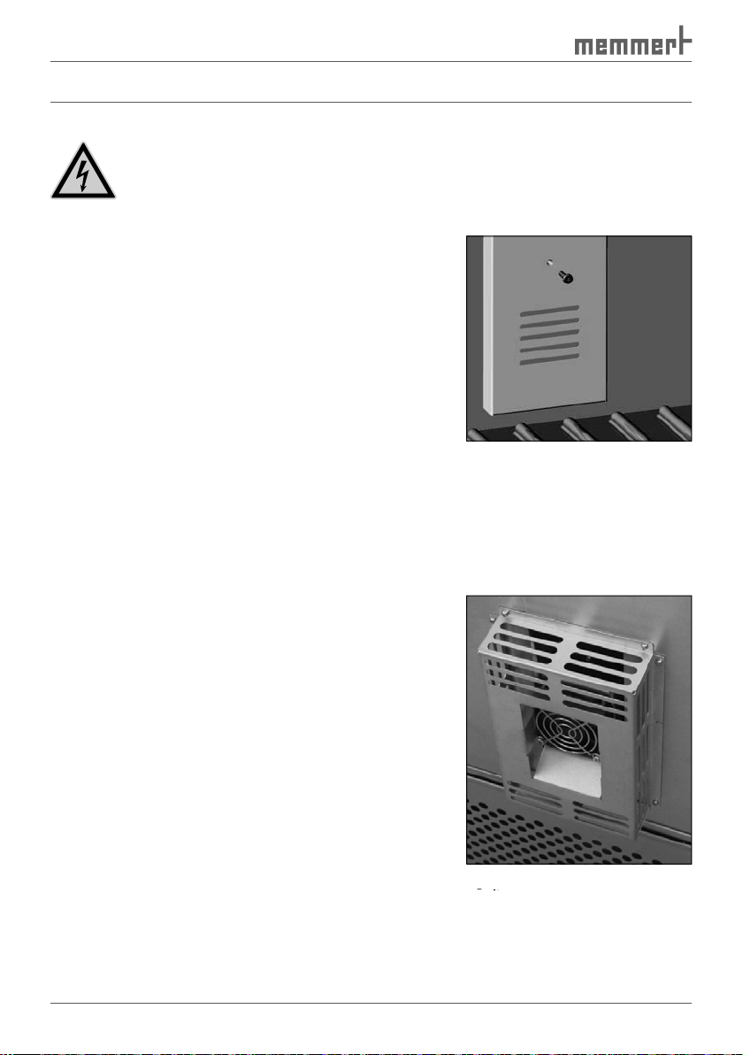
function and long lifetime of the
from the condenser (
, no. 1)
amount).
After the screws (2) have been
front (3) can be removed and the
After the screws have been loos-
to clean the refrigeration module
from both sides if necessary.
Every three months
Every three months
).
Annually
Annually
that the hinge screws are not loose.
).
). Replace them if they are
supply, see service
Additional maintenance every two years, for models with CO
Additional maintenance every two years, for models with CO
2
supply
supply
4
Fig. 33
Cooling compressor
1
3
2
Page 66

fluorescent tubes only with
fluorescent tubes of the same type; e.g. UV
fications, please refer to chapter "
Technical data
" on page
.
).
).
Fig. 34
Open the bayonet
catch and pull off the plug
Fig. 34
Fig. 34
Open the bayonet
Open the bayonet
Fig. 35
Pull out the illumination box
Turn the illumination box around and place it carefully on a smooth surface so that the
fluorescent tubes are on top (
).
4.
).
Fig. 36
Turn around the illumination
box
Fig. 36
Fig. 36
Fig. 37
Remove Allen screws and retaining plate
and take out the glass cover.
Fig. 37
Fig. 37
Remove Allen screws and retaining plate
Remove Allen screws and retaining plate
Page 67

the tubes carefully (
).
2
Fig. 38
Remove the plastic fixing and slide to the middle.
Pull the tubes carefully out of the holder.
Remove the plastic fixing and slide to the middle.
Remove the plastic fixing and slide to the middle.
Attach the glass cover and fix it with the restraining plate. To do so, screw in the two Allen
1
1
2
Page 68

Adjusting door
A well-closing door is indispensable for cooled
appliances optimally guarantee the tight closing
the door closes exactly despite this, an adjust-
).
The top section (1) of the door hinge can be
the two screws (2) at the top and bottom of the
Adjusting door:
Adjust the door by turning the eccentric (3)
with a screwdriver.
Apply the locking paint to the headless
The locking plate (
) can also be adjusted
Tighten the screws again.
Warning!
After removing covers,
voltage-carrying parts may
an electric shock if you touch
these parts. Disconnect the
any covers. Any work
electricians.
2
Fig. 39
Adjusting door
Adjusting door
Adjusting door
Mounting bolts
3
Eccentric tappet
Eccentric socket
Eccentric tappet
Eccentric tappet
5
Headless screw
Fig. 40
Adjusting locking plate
6
Screw
Locking plate
1
3
4
5
6
7
Page 69

Storage
The cooled incubator may only be stored under the following conditions:
frost-free
This product is subject to the Directive 2002/96/EC on Waste Electrical Electronic
th
Any appliances that are infected, infectious or contaminated with
The appliance may not be left at public or communal recycling or col-
Page 70

Index
A
Accessories 19
Accidents 10
Acoustic signal 52
Additional fittings 13
Adjusting door 68
Air circulation 27
Alarm 52
, , ,
Alterations 9
Ambient conditions 19
Appliance error 48
Aqua dest 23
ASF 56
Automatic temperature
, , ,
value 53
,
,
,
,
toring 54
,
,
,
,
,
, , ,
,
,
,
47
,
, 48, , , , ,
Page 71

, , ,
,
,
T
Technical data 17
Temperature calibration 59
,
Temperature comparison 59
Temperature deviation 60
Temperature limiter 54
Temperature monitor 56
Temperature monitoring 53
Temperature protection 49
Temperature sensor 53
Tolerance band ASF 53
Transport 20
TWW temperature monitor-
tion 55
,
,
, , , , ,
,
Warning messages 57
Water connection 14
,
,
Water specifications 23
Water tank 23
Weekday 52
Week time switch 29
,
Weight 17
What to do in case of ac-
X
XTADMIN 57
Year 52
Page 72

Memmert GmbH + Co KG | PO Box 1720 | D-91107 Schwabach, Germany | Phone +49 (0) 9122-925-0 | Fax +49 (0) 9122-145-85 | E-Mail: service@memmert.com | www.memmert.com
28.06.2013
ICH englisch
D23989
 Loading...