

Page 1
CLIMATE CHAMBER ICH/ICH L
ICH
ICH L
OPERATING
INSTRUCTIONS
100% ATMOSAFE. MADE IN GERMANY.
www.memmert.com | www.atmosafe.net
Page 2

Willi Memmert Straße 90-96
When contacting customer service, always quote the product serial number on the nameplate
Willi-Memmert-Str. 90-96
We reserve the right to make changes
Page 3

About this manual
About this manual
This manual describes the setup, function, transport, operation and maintenance of climate
the task of operating and/or maintaining the respective appliance.
there is something you do not understand, or certain information is missing, ask your man-
Versions
The appliances are available in different configurations and sizes. If specific equipment fea-
tures or functions are available only for certain configurations, this is indicated at the relevant
The functions described in this manual refer to the latest firmware version.
from the actual appearance. Function and operation are identical.
AtmoCONTROL, observe the separate
This instruction manual belongs with the appliance and should always be stored where
whereabouts of this instruction manual. We recommend that it is always stored in a protected
tion, the operating instructions must go with it.
www.memmert.com/de/service/downloads/bedienungsanleitung/
www.memmert.com/de/service/downloads/bedienungsanleitung/
Page 4

4 D30381 | Date 10/2014
.................................................................................................
........................................................................................................................
...............................................................................................
...................................................................................................
...................................................................................................................
..............................................................................................................................
............................................................................................................................
.........................................................................................................................
........................................................................................................
..........................................................................................................................
4. Putting into operation 21
4.1 Connecting the appliance
.................................................................................................
4.2 Fill up and connect the water tank
4.3 Switching on
......................................................................................................................
..............................................................................................................
.......................................................................................................
..........................................................................................................
.................................................................................................................................
...............................................................................................................
Contents
Page 5

................................................................
................................................
40
......................................................................................................................
41
............................................................................................................................
42
.......................
43
49
.............................................................................................................................
................................................................................................................................
.............................................................................................................................
...............................................................................................................................
.............................................................................................................................
............................................................................................................
..............................................................................................................................
Page 6
Terms and signs used
you of possible dangers or to give you hints that are important in avoiding injury or damage.
Terms used
Warning signs (warning of a danger)
tion
toppling
the mains
Wear gloves
Wear safety
Wear UV
Prohibition signs (forbidding an action)
Regulation signs (stipulating an action)
Other icons
Page 7
The appliances described in this manual are technically sophisticated, manufactured using
Warning!
After removing covers, live parts may be exposed. You may receive
an electric shock if you touch these parts. Disconnect the mains plug
the electrical equipment of the appliances.
Warning!
When loading the appliance with an unsuitable load, poisonous or
appliance to explode, and people could be severely injured or poi-
which do not form any toxic or explosive vapours when heated up
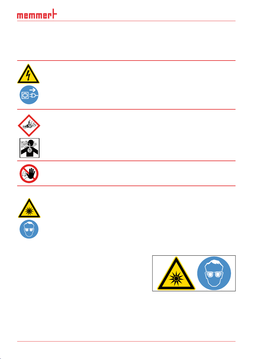
Warning!
Additional safety regulation for the model ICH L
Warning!
when opening the door of the ICH L. This is indicated by the warn-
The model ICH L has warning labels attached to its
UV
These stickers must not be removed and must always
from Memmert customer service.
Fig. 1
Warning sign on the door
Page 8

The appliance may only be operated and maintained by persons who are of legal age and
The owner of the appliance
tions, and train staff accordingly;
work is carried out properly (see page 57);
through corresponding instructions and inspections;
The appliance is not
which cannot form any toxic or explosive vapours at the set temperature and which cannot
The appliance may not be used for drying, vaporising and branding paints or similar materi-
the direct vicinity of the appliance.
The manufacturer is not liable for any damage, danger or injuries that result from unauthor-
Page 9
The appliance may only be used in a flawless condition. If you as the operator notice irregu-
your superior.
You can find information on eliminating malfunctions from page 38.
PLUS
ON
344.4
4444.
TEMP
Set
°C
°C
FLAP
40%
TIMER
hd
1002
End Sept.29 22 24
FAN
%0
%
100
ALARM
max
444.4°C
auto
+
/
-
0.0K
min
444.4°C
ONN
Manu
44.Sept
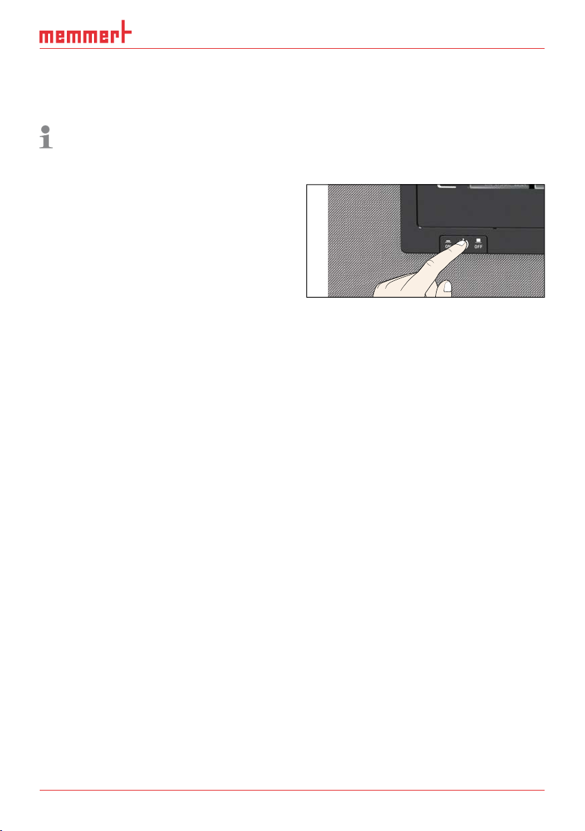
Fig. 2
Switch off the appliance by pressing the
main switch
Page 10
D30381 | Date 10/2014
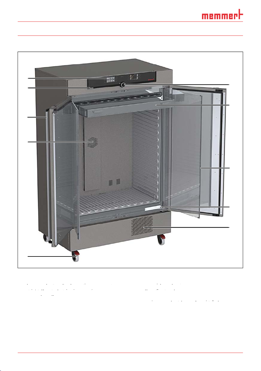
Construction
1
Fig. 3
Construction
keys and LCD displays (see page 25)
2
3
Door handle
4
5
Nameplate (see page 13)
8
Inner glass door
Nameplate (see page 13)
Nameplate (see page 13)
9
Illumination box with fluorescent tubes
Inner glass door
Inner glass door
2
3
4
5
10
9
8
7
6
Page 11

The appliance can heat up the interior to up to 60 °C and cool it down to –10 °C (without
The model ICH L is equipped with an
fluorescent tubes. The chamber load can be illuminated with UV light and/or daylight.
the interior, stainless steel (Mat.No. 1.4301 – ASTM 304) is used, which stands out through
The chamber load for the appliance must be carefully checked for chemical compatibility with
the materials mentioned. A material resistance table can be requested from the manufacturer.
Appliance fuse: Safety fuse 250 V/15 A, quick-blow
The temperature controller is protected with a miniature fuse 100 mA (160 mA at 115 V)
This appliance is intended for operation on an electrical power system with a system imped-
of a maximum of 0.292 ohm at the point of transfer (service line). The operator
of a maximum of 0.292 ohm at the point of transfer (service line). The operator
these requirements. If necessary, you can ask your local energy supply company what the
Page 12
D30381 | Date 10/2014
The communication interfaces are intended for appliances which meet the requirements of
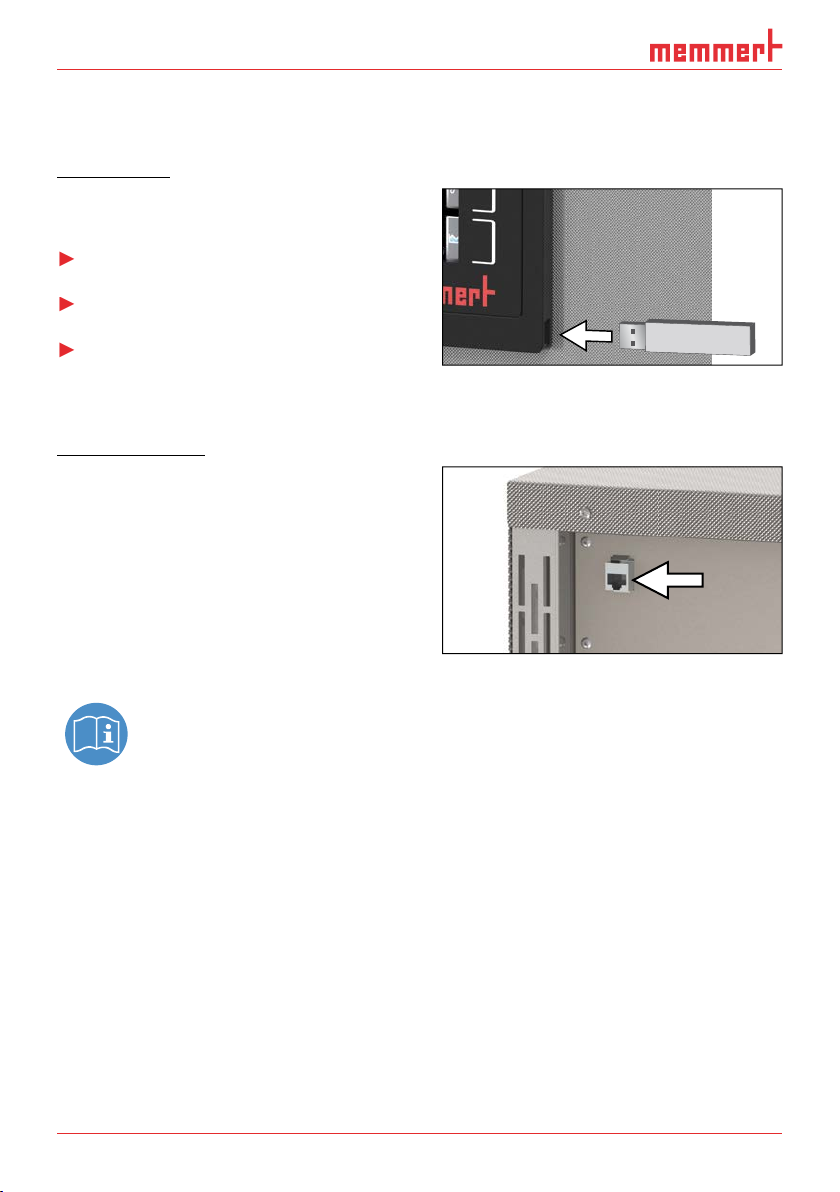
The appliance is fitted by default with a
tion. This way, you can
transfer software stored on a USB storage
transfer user ID data stored on a USB stor-
The USB port is located on the right side of the ControlCOCKPIT (Fig. 4).
Ethernet interface
Via Ethernet interface, the appliance can be
to a
AtmoCONTROL soft-
ware to the appliance and read out protocols.
The Ethernet interface is located on the rear of
the appliance (Fig. 5).
44 .
You will find a description of how to transfer programmes via Ethernet in the en-
AtmoCONTROL manual.
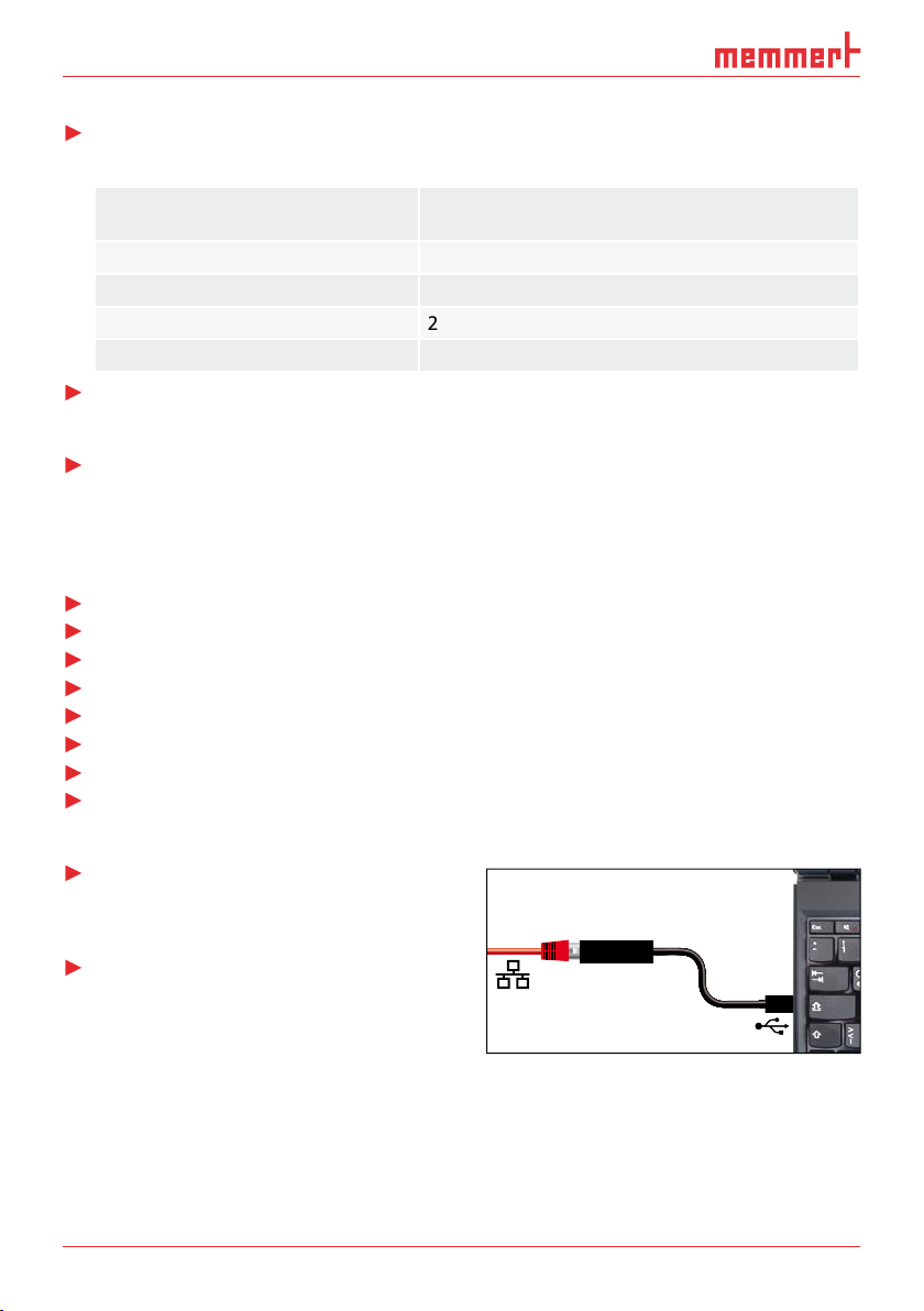
With an optional USB to Ethernet converter, the appliance can be directly connected to a com-
Fig. 4
Fig. 5
Ethernet interface
Page 13
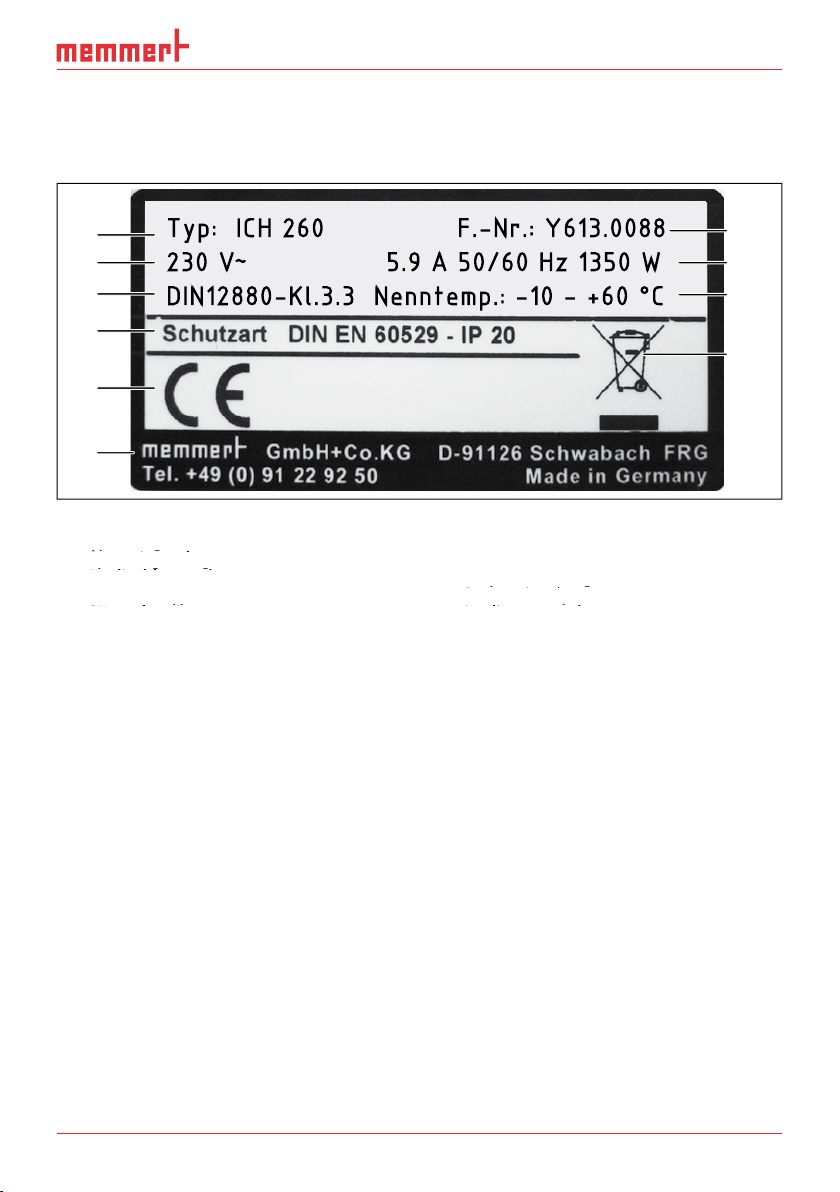
Designation
The nameplate (Fig. 6) provides information about the appliance model
technical data. It is attached to the front of the appliance, on the right behind the door (see
Fig. 6
Nameplate (example)
3
Applicable standard
Protection type
5
Address of manufacturer
Disposal note
8
9
Appliance number
1
2
3
4
5
6
Typ: ICH 260 F.-Nr.: Y613.0088
230 V
~
5.9 A 50/60 Hz 1350 W
DIN12880-Kl.3.3 Nenntemp.: -10 - +60 °C
10
9
8
7
Page 14
D30381 | Date 10/2014
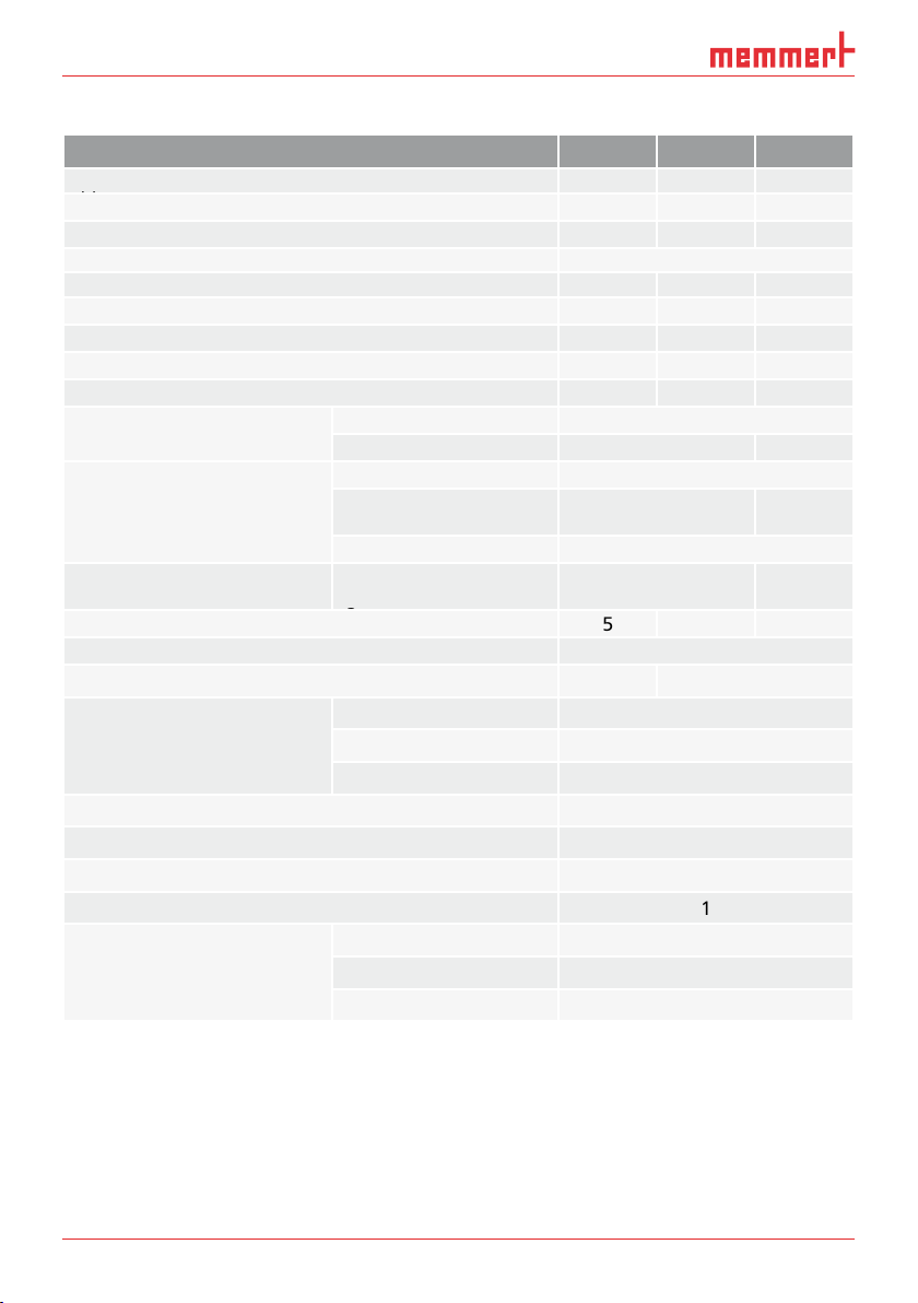
Technical data
Appliance size 110 260 750
Appliance width D* [mm]
Appliance width D* [mm]
Appliance height E* [mm]
Appliance depth F* (without door handle) [mm]
480
400
Weight including packaging [kg]
Working temperature range
with humidity
without humidity
with light
Adjustment precision (°C)
Adjustment range humidity (% rh)
Adjustment precision humidity (% rh)
Page 15
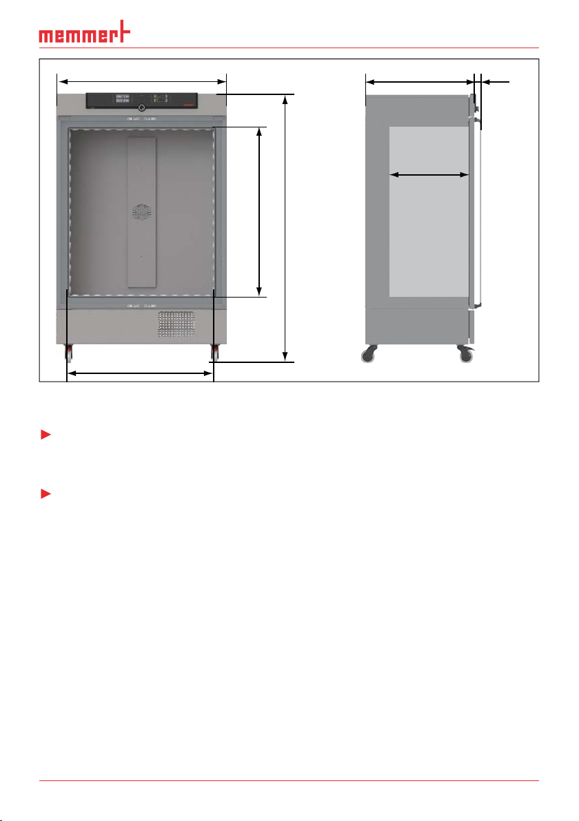
D
Fig. 7
Dimensions
Applied
the member states on electromagnetic compatibility). Standards complied with:
You can download the EC declaration of conformity of the appliance online:
F
56
C
B
E
A
Page 16
D30381 | Date 10/2014
Ambient conditions
The appliance may only be used in enclosed areas and under the following ambient condi-
tions:
Ambient temperature
Altitude of installation
The appliance may not be used in areas where there is a risk of explosion. The ambient air
Water tank with connection hose
AtmoCONTROL manual
The operating instructions at hand
Tank holder (only for appliances of size 750
, see page 22)
Optional
Fig. 8
Converter USB to Ethernet
Page 17
transport and
Warning!
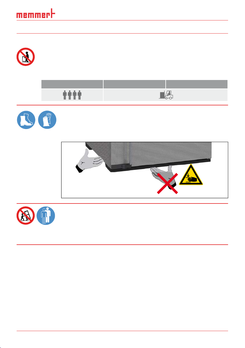
110 260 750
Warning!
You may get your hands or feet squashed when transport-
Warning!
The appliance could fall over and seriously injure you. Never
tilt the appliance and transport it in upright position and
without load only (except for standard accessories such as
Page 18

D30381 | Date 10/2014
The appliance is packed in cardboard and is delivered on a wooden palette.
Transport
The appliance can be transported in three ways:
With a
forklift truck; move the forks of the truck entirely under the pallet.
To avoid damage, do not unpack the appliance until you reach the installation site.
transport damage
Page 19

Warning!
and injure you or other people. Always attach the appliance to a wall
with the tilt protection (see page 20). In case there is not enough
The appliance may only be installed on the fl oor.
The
The distance between the wall and the rear of the appliance must be at least 15 cm. The clear-
the cooling unit at the appliance front.
≥ 20 cm
Fig. 9
Minimum clearance from walls and ceiling
≥ 5 cm ≥ 15 cm
≥ 5 cm
Page 20
D30381 | Date 10/2014
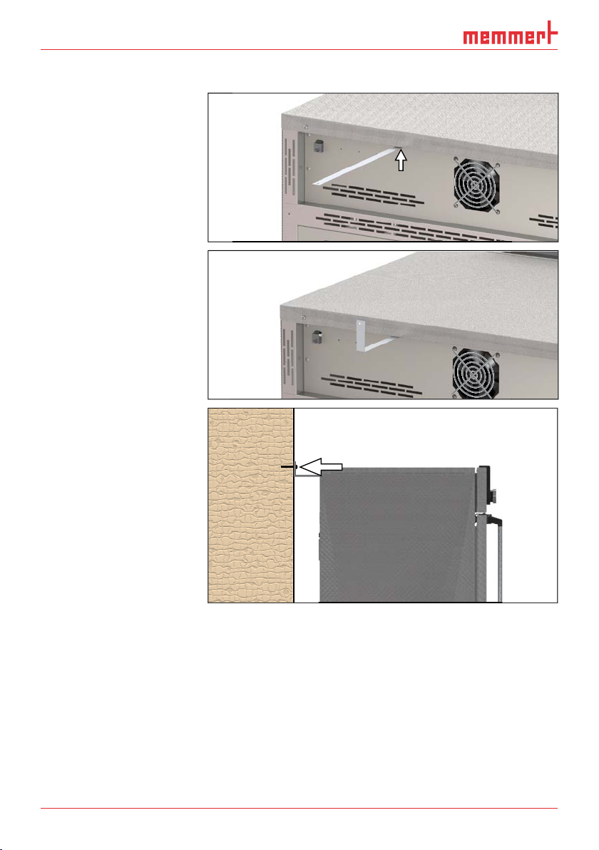
Tilt protection
Attach the appliance to a
wall with the tilt protection.
The tilt protection is included
tion upwards by 90 ° in
the desired distance to
the wall (consider the
wall, see Fig. 9).
tion to a suitable wall.
Page 21

The first time the appliance is operated, it must not be left unattended until it has reached
the steady state.
tion and power ratings (see nameplate and “Technical
failure or emergencies;
VDE 0510/DIN EN 50272; regulations must be strictly adhered to (production conductivity
The water used must have a pH value between 5 and 7 and be chlorine-free.
Fig. 10
Connect the power
cable to the rear of the appliance
Fig. 10
Fig. 10
Connect the power
Connect the power
Page 22

D30381 | Date 10/2014
wall mounting, the tank holder also has two drill holes (fastening material not included in the
Fig. 11
Water connection
Fig. 12
The starting process is shown by three animated white
. If the dots have another colour, an error has
After the first start-up, the appliance display is set to
the following chapter first.
PLUS
ON
344.4
4444.
TEMP
Set
°C
°C
FLAP
40%
TIMER
hd
1002
End Sept.29 22 24
FAN
%0
%
100
ALARM
max
444.4°C
auto
+
/
-
0.0K
min
444.4°C
ONN
Manu
44.Sept
Fig. 13
Switching on
the ap-
pliance
Page 23

Warning!
When in operation, small amounts of condensed water may leak
from the appliance. Always wear shoes with slip-proof soles and
wipe up the condensed water immediately.
The surfaces in the appliance‘s interior and the chamber load may
appliance.
The appliance may only be operated by persons who are of legal age and have been instruct-
training may only work with the appliance under the continuous supervision of an experi-
To open the door, pull the door handle to the side (to the left or to the right, depending
vented with the door ajar in case of high temperature inside the chamber. The door can
then be opened completely (B).
To close the appliance, push the door closed and the door handle to the side (C).
Loading – Models 30 -1060
Open / close the door
Fig. 14
Opening and closing the door
A
C
B
Page 24

D30381 | Date 10/2014
Warning!
Warning!
When loading the appliance with an unsuitable load, poisonous or
appliance to explode, and people could be severely injured or poi-
to the composition of materials, they must not be loaded into the
appliance.
the chamber load for chemical compatibility with the materials of the appliance
The chamber must not be
the side walls or right below
the ceiling of the chamber
the set temperature may
To achieve the correct heating capacity, the type of drawer used – Grid or Shelf – must be
(see page 54).
warning messages are displayed, e.g. if the temperature is exceeded. In programme mode,
the parameters defined, the programme description, the programme segment currently active
Correct placement of the
chamber load
Page 25

PLUS
344.4
444 4.
TEMP
Set
°C
°C
FLAP
40%
TIMER
hd
1002
End Sept.29 22 24
FAN
%0
%
100
ALARM
max
444.4°C
auto
+
/
-
0.0K
min
444.4°C
ONN
Manu
44.Sept
PLUS
344.4
444 4.
TEMP
Set
°C
°C
FLAP
40%
TIMER
hd
1002
End Sept.29 22 24
FAN
%0
%
100
ALARM
max
444.4°C
auto
+
/
-
0.0K
min
444.4°C
ONN
Manu
44.Sept
5 6 7 8 91 2 3 4
Fig. 16
depending on appliance size)
Fig. 16
Fig. 16
Activation key for temperature setpoint
adjustment
Activation key for temperature setpoint
Activation key for temperature setpoint
2
Setpoint and actual temperature display
adjustment
adjustment
3
Fan speed display
Setpoint and actual temperature display
Setpoint and actual temperature display
4
Activation key for fan speed setting
Fan speed display
Fan speed display
5
Switch to menu mode (see page 42)
Activation key for fan speed setting
Activation key for fan speed setting
Interior lighting activation key (only for
Switch to menu mode (see page 42)
Switch to menu mode (see page 42)
model ICH L)
Interior lighting activation key (only for
Interior lighting activation key (only for
Display interior lighting (only for model
ICH L)
8
Appliance state and programme display
9
Activation key for the appliance state
Appliance state and programme display
Appliance state and programme display
Activation key digital backwards counter
Activation key for the appliance state
Activation key for the appliance state
with target time setting, adjustable from 1
Activation key digital backwards counter
Activation key digital backwards counter
minute to 99 days
with target time setting, adjustable from 1
with target time setting, adjustable from 1
Display digital backwards counter with
target time setting, adjustable from 1 min-
Display digital backwards counter with
Display digital backwards counter with
ute to 99 days
target time setting, adjustable from 1 min-
target time setting, adjustable from 1 min-
Humidity control display
ute to 99 days
ute to 99 days
Humidity control activation key
Humidity control display
Humidity control display
with the turn control)
Activation key setting the temperature
and humidity monitoring
Activation key setting the temperature
Activation key setting the temperature
Display temperature and humidity moni-
and humidity monitoring
and humidity monitoring
toring
20
Activation key for graphic representation
Activate the desired parameter (e.g. tem-
the respective display. The activated dis-
30.0
%rh
50.0
%CO2
Programm 12
Fr 20.10.2010 20:31
min
000°C
MENU
30.0
%rh
50.0
%CO2
Programm 12
Fr 20.10.2010 20:31
min
000°C
MENU
TIMER
turn control to the left
%
100
ALARM
max
444.4°C
auto
+
/
-
0.0K
min
444.4°C
Manu
44.Sept
TEMP
22.4°C
Set 37
TIMER
TIMER
30m04h
44h:44m
End
13:30 23.11.
End 14:45
ON
ON
FAN
50%
.0°C
HUMIDITY
30%rh
Set 30 %rh
ON
ON
min
000°C
min
35.5°C
auto
LIGHT
100
0
ALARM
ALARM
Fr 20.10.2010 20:31
13:44
12.Sept.2012
%DL
%UV
of °C
max
max
38.5°C
000°C
auto off
+
+
0.0K
-
99K
-
Manual Mode
Holz trocknen
aufheizen
09:12h
GRAPH
0 12
off
%rh°C
19 2015 16 17 1810 11 12 13 14
TEMP
22.4°C
37.0°CSet
.5°C100
TEMP
22.4°C
37.0°CSet
Page 26

D30381 | Date 10/2014
The display returns to normal and the
%
100
ALARM
max
444.4°C
auto
+
/
-
0.0K
min
444.4°C
Manu
44.Sept
TEMP
Additional parameters can be set accordingly.
want to exit. The appliance restores the former values.
The appliance can be operated in different modes:
trolCOCKPIT. Operation in this mode is described in chapter 5.4.4 .
AtmoCONTROL software at a computer / laptop and then transferred
to the appliance from a USB stick or via Ethernet. Operation in this mode is described in
via remote control
The status display shows you which operating mode or operating state the appliance is
Appliance is
Appliance is in manual mode
The example on the right shows the appliance in manual
When the appliance is in timer mode,
is
30.0
%rh
50.0
%CO2
Programm 12
Fr 20.10.2010 20:31
min
000°C
max
000°C
.5°C100
MENU
30.0
%rh
50.0
%CO2
Programm 12
Fr 20.10.2010 20:31
min
000°C
max
000°C
MENU
TIMER
22.4°C
TEMP
37.0°CSet
23.2°C
Set 37
.0°C
►
►
►
►
■
12.Sept.2012
Manual Mode
12.Sept.2012
13:44
13:44
Timer active
Page 27

When the appliance is in remote control mode, the
Manual mode
Adjustment options
Adjustment options
As described in chapter 5.4.2 , you can set the following
Temperature
Temperature
Adjustment range: dependent on model and operating mode (see
symbol.
symbol.
You can select °C or °F as the temperature unit displayed (see
Adjustment option: 10 % to 100 % in steps of 10%
Adjustment range: 10 to 80 % rh
symbol.
symbol.
Adjustment range:
Setting interior lighting
Setting interior lighting
Activate light display. To do so, press the
entry
is selected
%
100
ALARM
max
444.4°C
auto
+
/
-
0.0K
min
444.4°C
Manu
44.Sept
Holz trocknen
aufheizen
Fr 20.10.2010 20:31
%rh
GRAPH
off
%
100
ALARM
max
444.4°C
auto
+
/
-
0.0K
min
444.4°C
Manu
44.Sept
Manual Mode
12.Sept.2012
13:44
turn control to the left or
%
100
ALARM
max
444.4°C
auto
+
/
-
0.0K
min
444.4°C
Manu
44.Sept
TEMP
23.2°C
Set 180
TEMP
.0°C
22.4
Set
FAN
50
HUMIDITY
34%
Set
LIGHT
%DL
100
%UV
0
LIGHT
%DL
0
%UV
0
ONON
ALARM
of °C
ALARM
min
35.5°C
min
auto
000°C
max
max
38.5°C
000°C
auto off
+
+
-
0.0K
-
70
99K
37.0
°C
°C
%
rh
%rh
°C
09:12h
0 12
LIGHT
100
0
%DL
%UV
Page 28

D30381 | Date 10/2014
%
100
ALARM
max
444.4°C
auto
+
/
-
0.0K
min
444.4°C
Manu
44.Sept
LIGHT
4.
turn control to the left or
%
100
ALARM
max
444.4°C
auto
+
/
-
0.0K
min
444.4°C
Manu
44.Sept
%
100
ALARM
max
444.4°C
auto
+
/
-
0.0K
min
444.4°C
Manu
44.Sept
As soon as the illumination boxes are active, the refrigeration unit has to compensate the
Timer)
the timer display. The timer display is
30.0
50.0
.5°C100
MENU
30.0
50.0
MENU
Set 180.0
Turn the turn control until the desired
time is shown beneath, in a smaller font.
%
100
ALARM
max
444.4°C
auto
+
/
-
0.0K
min
444.4°C
Manu
44.Sept
format. For 24 hours and more, the format dd:hh (days:hours) is used. The maximum
100
0
LIGHT
100
100
LIGHT
100
100
%DL
%UV
%DL
%UV
%DL
%UV
TIMER
04 mh 3
13:30 23.11.
End
-
Ende
TIMER
--h- m
9:00 23.11.
0
Page 29

%
100
ALARM
max
444.4°C
auto
+
/
-
0.0K
min
444.4°C
Manu
44.Sept
The display now shows the remaining time
The status display
TIMER
The set values can be changed at any
time during the timer. The changes are effective immediately.
ture is reached or if it should start right after activation (see page 46). If the timer runs
When the timer has elapsed, the display shows 00h:00m. All func-
tions (heating etc.) are switched off. In addition, an acoustic alarm
To deactivate the timer, open the timer display by pressing the
to reduce
the timer setting until --:-- is displayed. Confirm with the confirma-
tion key.
AtmoCONTROL software. Transfer to the appliance is possible using the provided USB storage
A description of how to create and save programmes can be found in the separate
AtmoCONTROL software manual.
Starting a programme
Starting a programme
the status display. The current operating
(
).
0
0
Ende
30m04h
13:30 23.11.
12.Sept.2012
Timer active
TIMER
End
TIMER
End
13:44
00m00h
13:30 23.11.
--m--h
9:00 23.11.
Fr 20.10.2010 20:31
Manual mode
manueller Betrieb
Activate
GRAPH
8
80
40
4
17:4413.Sept.2012
Page 30

D30381 | Date 10/2014
Turn the turn control until the
start
%
100
ALARM
max
444.4°C
auto
+
/
-
0.0K
min
444.4°C
Manu
44.Sept
Test 012
first (description from page 53).
To start the programme, press the confir-
the programme description (in this exam-
Test 012
)
the programme segment description, in
this example
the current run (in case of loops)
%
100
ALARM
max
444.4°C
auto
+
/
-
0.0K
min
444.4°C
Manu
44.Sept
You cannot change any parameters (e.g. the temperature) at the appliance while a
and
can still be used.
You can cancel an active programme at any
time.
the status display. The status display is
0
Turn the turn control until the
stop
%
100
ALARM
max
444.4°C
auto
+
/
-
0.0K
min
444.4°C
Manu
44.Sept
The programme is cancelled.
A cancelled programme cannot be
%
100
ALARM
max
444.4°C
auto
+
/
-
0.0K
min
444.4°C
Manu
44.Sept
End of programme
End of programme
The display shows
when the programme
ready
Test 012
Ramp 1
10:4412.Sept.2012
10:4412.Sept.2012
Fr 20.10.2010 20:31
%
%
manueller Betrieb
Test 012
Ramp 3
GRAPH
8
80
10:4412.Sept.2012
10:4812.Sept.2012
Cancel program
Test 012
10:4912.Sept.2012
End
Test 012
10:4912.Sept.2012
End
Test 012
Page 31

You can now
is highlighted in colour and
is highlighted in colour and
Temperature monitoring
The appliance is equipped with a multiple overtemperature protection in accordance with
electronic temperature monitoring (TWW)
temperature monitor (
ASF)
The
temperature monitoring
tem-
display. The settings made apply to all
warning symbol is
warning symbol is
the menu mode (
which can be turned off by pressing the confirmation key. Information on what to do in this
PLUS
344.4
4444.
TEMP
Set
°C
°C
FLAP
40%
TIMER
hd
1002
End Sept.29 22 24
FAN
%0
%
100
ALARM
max
444.4°C
auto
+
/
-
0.0K
min
444.4°C
Manu
44.Sept
Holz trocknen
aufheizen
09:12h
Fr 20.10.2010 20:31
min
000°C
ALARM
of °C
max
000°C
auto off
99K
-
+
0 12
%rh°C
GRAPH
off
ONON
PLUS
344.4
4444.
TEMP
Set
°C
°C
FLAP
40%
TIMER
hd
1002
End Sept.29 22 24
FAN
%0
%
100
ALARM
max
444.4°C
auto
+
/
-
0.0K
min
444.4°C
Manu
44.Sept
TEMP
LICHT
%
100
ALARM
max
38.5°C
auto
+
/
-
0.0K
min
35.5°C
Manueller Betrieb
12.Sept.2012
13:44
344.4
444 4.
TEMP
Set
°C
°C
FLAP
40%
344.4
444 4.
TEMP
Set
°C
°C
FLAP
40%
22.4
37.0
TEMP
Set
°C
°C
°C22.4
TEMP
°CSet 37.0
°C
TEMP
TWW Set 38.5 °C
38.9
Fig. 17
22.4
Set
TWW Set 38.5 °C
TIMER
TIMER
30m04h
44h:44m
Ende
23.Nov 13:30
End14:45
12.Sept.2012
13:44
Manual Mode
ALARM
min
36.5 °C
auto
TEMP
TEMP
°C22.4
°C
°C
38.9
°CSet 37.0
37.0
°C
FEUCHTE
30.0%rh
Set 30.0%rh
max
38.5 °C
+
2.0K
-
Page 32
D30381 | Date 10/2014
Electronic temperature monitoring (
Electronic temperature monitoring (
The manually set monitoring temperature
of the overtemperature control is
to DIN 12 880. If the manually set monitoring temperature
is exceeded, the TWW takes
°C
Fig. 18
Schematic diagram of how TWW
temperature monitoring works
Emergency operation
Setting MAX
Set temperature
Controller error
t
Page 33

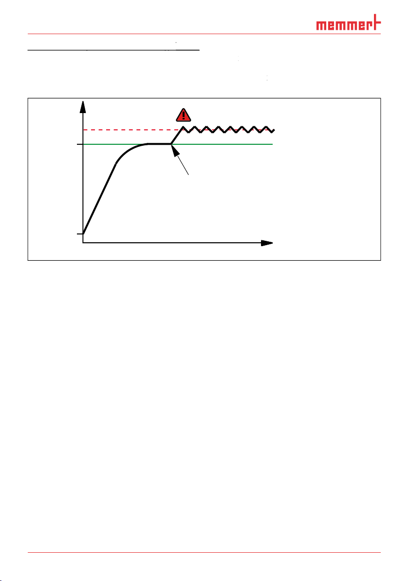
Automatic
temperature monitor (
temperature monitor (
ASF)
ASF is a monitoring device that automatically follows the set temperature setpoint within an
The ASF – if switched on – is automatically activated as soon as the actual temperature value
1 K) for the
first time (section A).
When the temperature violates the set tolerance band around the setpoint (in the example in
the new temperature setpoint is reached again (section E).
°C
Fig. 19
Schematic diagram of how the ASF temperature monitoring works
Mechanical temperature monitoring:
Mechanical temperature monitoring:
(TB)
(TB)
The appliance is equipped with a
If the electronic monitoring unit should fail
Adjusting temperature monitoring
Adjusting temperature monitoring
display. The temperature moni-
toring setting is automatically activated
).
%
100
ALARM
max
444
.4°C
auto
+
/
-
0.0
K
min
444
.4°C
Manu
44.Sept
Holz trocknen
aufheizen
09:12h
Fr 20.10.2010 20:31
min
000°C
ALARM
0 12
%rh°C
DRAPH
off
ON
ON
max
000°C
auto off
99K
-
+
ALARM
max
40
.0°C
auto
0.0
K
min
15
.0°C
+
-
Fig. 20
Resetting the mechanical temperature limiter
50°C
25°C
52°C
48°C
A B C D E
52°C
27°C
23°C
ASF active
48°C
AUTO AUTO AUTO
ASF alarm
ASF active ASF active
t
Page 34

D30381 | Date 10/2014
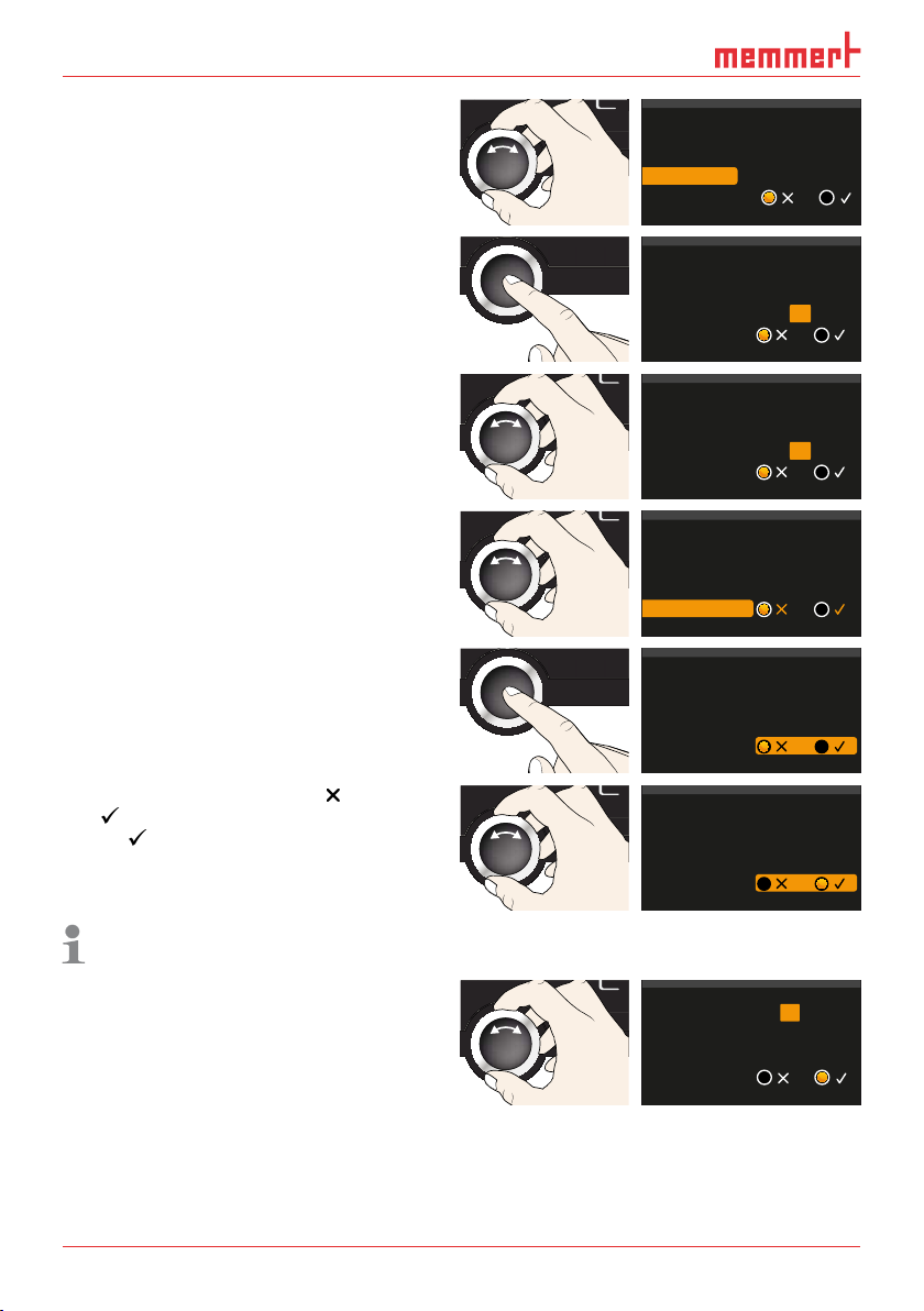
firmation key. The min setting (under-
temperature protection) is automatically
%
100
ALARM
max
444.4°C
auto
+
/
-
0.0K
min
444.4°C
Manu
44.Sept
ALARM
The lower alarm limit value cannot be set
the lowest temperature.
%
100
ALARM
max
444.4°C
auto
+
/
-
0.0K
min
444.4°C
Manu
44.Sept
4.
The max display (overtemperature protec-
tion) is activated.
%
100
ALARM
max
444.4°C
auto
+
/
-
0.0K
min
444.4°C
Manu
44.Sept
By turning the turn control, adjust the
The monitoring temperature must be set
temperature. We recommend 1 to 3 K.
%
100
ALARM
max
444.4°C
auto
+
/
-
0.0K
min
444.4°C
Manu
44.Sept
Accept the upper alarm limit value by
).
%
100
ALARM
max
444.4°C
auto
+
/
-
0.0K
min
444.4°C
Manu
44.Sept
With the turn control, select ON (
) or
).
%
100
ALARM
max
444.4°C
auto
+
/
-
0.0K
min
444.4°C
Manu
44.Sept
The ASF tolerance band setting is acti-
vated.
%
100
ALARM
max
444.4°C
auto
+
/
-
0.0K
min
444.4°C
Manu
44.Sept
With the turn control, adjust the desired
tolerance band, e.g. 2.0 K.
We recommend a tolerance band of 1 to
%
100
ALARM
max
444.4°C
auto
+
/
-
0.0K
min
444.4°C
Manu
44.Sept
min
15.0 °C .0°C
auto
ALARM
min
°C
35 5.
auto
ALARM
min
°C
35 5.
auto
ALARM
min
°C
35 5.
auto
ALARM
min
35.5°C
auto
max
40
+
-
max
40.0°C
+
-
max
40 0.
+
-
max
38 5.
+
-
max
38.5 °C
+
-
0.0K
0.0K
0.0
0.0K
0.0K
°C
K
°C
ALARM
min
35.5°C
auto
ALARM
min
°C
35 5.
auto
ALARM
min
°C
35 5.
auto
max
38.5 °C
+
-
max
38.5 °C
+
-
max
38.5 °C
+
-
0.0K
0.3
2.0
K
K
Page 35

Temperature monitoring is now active.
%
100
ALARM
max
444.4°C
auto
+
/
-
0.0K
min
444.4°C
Manu
44.Sept
this is indicated by the humidity display:
the actual humidity is highlighted in red
is shown ( Fig.
menu (see page
warning and error messages on page
Adjusting humidity monitoring
Adjusting humidity monitoring
ALARM
display. The temperature moni-
toring setting is automatically activated.
%
100
ALARM
max
444.4°C
auto
+
/
-
0.0K
min
444.4°C
Manu
44.Sept
Holz trocknen
aufheizen
09:12h
Fr 20.10.2010 20:31
0 12
%rh°C
DRAPH
off
ON
ON
Turn the turn control until the humidity
is highlighted.
%
100
ALARM
max
444.4°C
auto
+
/
-
0.0K
min
444.4°C
Manu
44.Sept
CO2
GAS
ALARM
max
44.4%rh
min
44.4%rh
CO2
GAS
ALARM
max
444.4°C
auto
+
/
-
0.0K
min
444.4°C
CO2
GAS
ALARM
auto
min
444.4°C
max
444.4°C
+
/
-
4.4K
CO2
GAS
ALARM
max
44.4%rh
min
44.4%rh
CO2
GAS
ALARM
min
44.4%rh
max
44.4%rh
Accept the selection by pressing the con-
firmation key. The lower humidity alarm
%
100
ALARM
max
444.4°C
auto
+
/
-
0.0K
min
444.4°C
Manu
44.Sept
CO2
GAS
ALARM
max
44.4%rh
min
44.4%rh
CO2
GAS
ALARM
max
444.4°C
auto
+
/
-
0.0K
min
444.4°C
CO2
GAS
ALARM
auto
min
444.4°C
max
444.4°C
+
/
-
4.4K
CO2
GAS
ALARM
max
44.4%rh
min
44.4%rh
CO2
GAS
ALARM
min
44.4%rh
max
44.4%rh
4.
%
100
ALARM
max
444.4°C
auto
+
/
-
0.0K
min
444.4°C
Manu
44.Sept
°C
FLAP
40%
hd
FAN
%0
%
100
ALARM
max
444.4°C
auto
+
/
-
0.0K
min
444.4°C
Manu
44.Sept
Holz trocknen
aufheizen
09:12h
Fr 20.10.2010 20:31
000°C
ALARM
of °C
max
000°C
auto off
99K
-
+
0 12
%rh°C
GRAPH
off
ON
ON
°C
FLAP
40%
hd
FAN
%0
%
100
ALARM
max
444.4°C
auto
+
/
-
0.0K
min
444.4°C
Manu
44.Sept
LICHT
%
100
ALARM
max
38.5°C
auto
+
/
-
0.0K
min
35.5°C
Manueller Betrieb
12.Sept.2012
13:44
FLAP
40%
FAN
%0
FLAP
40%
FAN
%0
FEUCHTE
30.0%rh
Set 30.0%rh
°C22.4
°CSet 37.0
Fig. 21
Humidity monitoring triggered
ALARM
min
36.5 °C
auto
HUMIDITY
°C22.4
°CSet 37.0
°C
FEUCHTE
HUMIDITY
30.0%rh
m
75.4
Set 30.0%rh
Set 70
%rh
.0%rh
m
75.4
Set 70
15.0°C
min
000°C
min
auto
%rh
.0%rh
ALARM
ALARM
max
38.5 °C
+
2.0K
-
max
max
40.0°C
000°C
auto off
+
+
0.0K
99K
-
-
min
ALARM
max
40.0%rh
min
20.0%rh
ALARM
max
40.0%rh
min
20.0%rh
ALARM
max
min
40.0%rh
50.0%rh
Page 36

D30381 | Date 10/2014
Accept the selection by pressing the con-
firmation key. The upper humidity alarm
%
100
ALARM
max
444.4°C
auto
+
/
-
0.0K
min
444.4°C
Manu
44.Sept
CO2
GAS
ALARM
max
44.4%rh
min
44.4%rh
ALARM
CO2
GAS
ALARM
max
444.4°C
auto
+
/
-
0.0K
min
444.4°C
CO2
GAS
ALARM
auto
min
444.4°C
max
444.4°C
+
/
-
4.4K
CO2
GAS
ALARM
max
44.4%rh
min
44.4%rh
CO2
GAS
ALARM
min
44.4%rh
max
44.4%rh
%
100
ALARM
max
444.4°C
auto
+
/
-
0.0K
min
444.4°C
Manu
44.Sept
CO2
GAS
ALARM
max
44.4%rh
min
44.4%rh
CO2
GAS
ALARM
max
444.4°C
auto
+
/
-
0.0K
min
444.4°C
CO2
GAS
ALARM
auto
min
444.4°C
max
444.4°C
+
/
-
4.4K
CO2
GAS
ALARM
max
44.4%rh
min
44.4%rh
CO2
GAS
ALARM
min
44.4%rh
max
44.4%rh
Accept the selection by pressing the
Alarm
the side.
%
100
ALARM
max
444.4°C
auto
+
/
-
0.0K
min
444.4°C
Manu
44.Sept
CO2
GAS
ALARM
max
44.4%rh
min
44.4%rh
CO2
GAS
ALARM
max
444.4°C
auto
+
/
-
0.0K
min
444.4°C
CO2
GAS
ALARM
auto
min
444.4°C
max
444.4°C
+
/
-
4.4K
CO2
GAS
ALARM
max
44.4%rh
min
44.4%rh
CO2
GAS
ALARM
min
44.4%rh
max
44.4%rh
The GRAPH display provides an overview of the chronological sequence of the set values and
the actual values as a curve.
Temperature profi le
display.
The display is enlarged and
the temperature profile
To change the time frame to
tion key next to the
ar-
to be displayed can now be
20:34
%
100
ALARM
max
444.4°C
auto
+
/
-
0.0K
min
444.4°C
Manu
44.Sept
To extend or reduce the time
frame to be displayed: Press
the activation key next to the
With the turn control, select
tion by pressing the confirma-
tion key.
%
100
ALARM
max
444.4°C
auto
+
/
-
0.0K
min
444.4°C
Manu
44.Sept
To close the graphical representation, again press the activation key which you have used to
min
50.0%rh
max
40.0%rh
12.09.2012
°C
100
40
80
39
60
40
38
20
0 4 8 12 16 20 24
14.00 16.00 18.00
Fr 20.10.2010 20:34
°C
100
40
39
38
12.09.2012
Fr 20.10.2010
80
60
40
20
0 4 8 12 16 20 24
14.00 16.00 18.00
ALARM
max
70.0%rh
min
50.0%rh
ALARM
max
70.0%rh
min
50.0 %rh
0 20:34
Page 37

Activate graphic representa-
tion as described above and
then press the activation key
tion.
20:34
12.09.2012
with the
turn control.
%
100
ALARM
max
444.4°C
auto
+
/
-
0.0K
min
444.4°C
Manu
44.Sept
20:34
the display range as described
%
100
ALARM
max
444.4°C
auto
+
/
-
0.0K
min
444.4°C
Manu
44.Sept
0 4 8 12 16 20 24
20:34
14.00 16.00 18.00
4.
PLUS
344.4
4444.
TEMP
Set
°C
°C
FLAP
40%
TIMER
hd
1002
End Sept.29 22 24
FAN
%0
%
100
ALARM
max
444.4°C
auto
+
/
-
0.0K
min
444.4°C
ONN
Manu
44.Sept
Fig. 22
Switching
off the appliance.
°C
100
40
80
39
60
40
38
20
0 4 8 12 16 20 24
14.00 16.00 18.00
Fr 20.10.2010
°C
100
12.09.2012
40
80
39
60
40
38
20
Fr 20.10.2010
%rh
°C
100
12.09.2012
80
80
60
60
40
40
20
Fr 20.10.2010
ON
Page 38

D30381 | Date 10/2014
Warning!
After removing covers, live parts may be exposed. You may receive
an electric shock if you touch these parts. Malfunctions requiring
work inside the appliance may only be rectifi ed by electricians. Ob-
Warning messages of the monitoring function
), the
the confirmation key is pressed, the acoustic alarm can be tempo-
Temperature monitoring
Description Cause Action See
Temperature alarm and
Automatic tem-
Temperature alarm and
The adjustable
temperature
temperature.
%
100
ALARM
max
444.4°C
auto
+
/
-
0.0K
min
444.4°C
Manu
44.Sept
TEMP
40.4°C
ASF Set 38.5 °C
TEMP
42.4°C
TWW Set 38.5 °C
Page 39

Description Cause Action See
Appliance does not heat
The mechanical
temperature lim-
Wait until the appliance
the right of the appliance
Water tank
Alarm display (
)
wait to see if the appliance
tact customer service.
Alarm display (
)
the filling level of the water
tank. If required, refill the
water tank.
tact customer service.
Description Cause Action See
HUMIDITY
55.4
Set 55
HUMIDITY
75.4
MaxAl Set 70
HUMIDITY
55.4
MinAl Set 60
%rh
.0%rh
%rh
.0%rh
%rh
.0%rh
Page 40

40
D30381 | Date 10/2014
Error description Cause of errors Rectifying errors See
was interrupted
fuse or power module
faulty
Appliance locked by USER
The appliance is in pro-
Wait until the end of
the programme or
timer mode or switch
Appliance is in "wrong"
temperature display
Temperature operating sen-
The appliance can
the temperature display
Temperature monitoring
The appliance can
temporarily be
the temperature display
TEMP
37.4°C
T:E-3 Set 37.0 °C
TEMP
37.4°C
AI E-3 Set 37.0 °C
TEMP
E-3 °C
Set 45.0 °C
Page 41

Error description Cause of errors Rectifying errors See
the humidity display
trol possible
When switching on
the appliance, the start
white
Cyan
The system files could
fonts and images could
ware update at mem-
In manual mode
After power supply has been restored, operation is continued with the parameters set. The
time and duration of the power failure are documented in the
In timer or programme mode
In timer or programme mode
the power supply, all appliance functions (heating, fan etc.) are switched off.
In remote control mode:
The previous values are restored. If a programme has been initiated via remote control, it is
HUMIDITY
E-6
Set 50
%rh
.0%rh
Page 42

42
D30381 | Date 10/2014
Menu mode
To
enter menu mode, press the MENU key.
To
PROGRAM
USER ID
PROTOCOL
PLUS
344.4
4444.
TEMP
Set
°C
°C
FLAP
40%
TIMER
hd
1002
End Sept.29 22 24
FAN
%0
%
100
ALARM
max
444.4°C
auto
+
/
-
0.0K
min
444.4°C
ONN
Manu
44.Sept
1 2 3 4 5 12 14 1513
Fig. 23
ControlCOCKPIT in menu mode
Language selection activation key
2
Language selection display
Language selection activation key
Language selection activation key
3
Date and time display
Language selection display
Language selection display
4
Date and time setting activation key
Date and time display
Date and time display
5
Exit menu mode and return to operating
Date and time setting activation key
Date and time setting activation key
mode
Exit menu mode and return to operating
Exit menu mode and return to operating
Setup activation key (basic appliance set-
tings)
Setup display (basic appliance settings)
tings)
tings)
8
Adjustment display
Setup display (basic appliance settings)
Setup display (basic appliance settings)
9
Adjustment activation key
Adjustment display
Adjustment display
with the turn control)
Programme setup activation key
Programme setup display
Programme setup activation key
Programme setup activation key
Protocol display
Programme setup display
Programme setup display
Protocol activation key
Protocol display
Protocol display
Acoustic signal adjustment activation key
Protocol activation key
Protocol activation key
Acoustic signal adjustment display
Acoustic signal adjustment activation key
Acoustic signal adjustment activation key
%
100
ALARM
max
444.4°C
auto
+
/
-
0.0K
min
444.4°C
Manu
44.Sept
TIME
LANGUAGE
SIGNALTÖNE
PROG
PROTOCOL
SETUP
ON
CALIB
ZEIT UND DATUM
SOUND
6 7 18 198 9 10 11 16 17
USER ID
Page 43

the change. A more detailed description is provided in the following, using the example of
Activate the desired parameter (in this
the corresponding activation key on the
LANGUAGE
OG
TIME
D
O
OCO
firmed by pressing the confirmation key
PROG
ZEIT UND DATUM
USER ID
PROTOCOL
LANGUAGE
PROGRAM
USER ID
PROTOCOL
SOUND
PLUS
344.4
4444.
TEMP
Set
°C
°C
FLAP
40%
TIMER
hd
1002
End Sept.29 22 24
FAN
%0
%
100
ALARM
max
444.4°C
auto
+
/
-
0.0K
min
444.4°C
ONN
Manu
44.Sept
With the turn control, select the desired
%
100
ALARM
max
444.4°C
auto
+
/
-
0.0K
min
444.4°C
Manu
44.Sept
SPRACHE
%
100
ALARM
max
444.4°C
auto
+
/
-
0.0K
min
444.4°C
Manu
44.Sept
SPRACHE
To return to the menu overview, press the
SIGNALTÖNE
PROG
ZEIT UND DATUM
CALIB
USER ID
PROTOCOL
PROGRAM
TIME
USER ID
PROTOCOL
SOUND
PLUS
344.4
4444.
TEMP
Set
°C
°C
FLAP
40%
TIMER
hd
1002
End Sept.29 22 24
FAN
%0
%
100
ALARM
max
444.4°C
auto
+
/
-
0.0K
min
444.4°C
Manu
44.Sept
You can now
SETUP
PROGRAM
TIME
USER ID
PROTOCOL
PROGRAM
US
ER I
D
PROTOCO
L
+30%
192.168.100.100
°C F
TWW TWB
SETUP
192.168.100.100
255.255. 0.0
°C F
TWW TWB
Grid Shelf
%
100
ALARM
max
444.4°C
auto
+
/
-
0.0K
min
444.4°C
Manu
44.Sept
ENGLISH
DEUTSCH
FRANCAIS
ESPANOL
SIGNALTÖNE
TIME
ON
ENGLISH
DEUTSCH
FRANCAIS
ESPANOL
ENGLISH
DEUTSCH
FRANCAIS
ESPANOL
IP address
Balance
Subnet mask
IP Adresse
Unit
Einheit
Alarm Temp
Alarm Temp
Timer mode
Timer Mode
Slide-in unit
SETUP
LANGUAGE
CALIB
SETUP
Page 44

44
D30381 | Date 10/2014
All other settings can be made accordingly. The settings possible are described in the follow-
display, you can set the following parameters:
the
and
of the appliance’s Ethernet interface (for connection to
the
of the temperature display (°C or °F, see page 45)
46
the type of the slide-in unit (grid or shelf, see page 46)
the defrosting system (
entries than can be
To display the hidden entries, use the turn control to scroll
work, each appliance must have its own unique IP address for identification. By default, each
LAN 1: 192.168.1.233
192.168.1.216
LAN 2: 192.168.1.215
LAN 3: 192.168.1.241
Editor
Programmname
Simulation Protokoll
-
+-+
INP 250 Test 01
180
.0°C
i
HPP 250 Labor
i
37
.0°C
44
.4%rh
5
STAND BY
Programm negnulletsniEllokotorPtäreG efliHnekcurD
AtmoCONTROL
Fig. 24
network (schematic example)
Setup
225
1/2
IP adress 255.145.136.
Subnet mask 255.255.0.0
Unit
°C F
Page 45

Activate the
display. The entry
is automatically highlighted.
PROGRAM
TIME
PROGRAM
TIME
US
D
O
OCO
SETUP
Accept the selection by pressing the con-
firmation key. The first three digits of the
%
100
ALARM
max
444.4°C
auto
+
/
-
0.0K
min
444.4°C
Manu
44.Sept
SETUP
With the turn control, set the new num-
%
100
ALARM
max
444.4°C
auto
+
/
-
0.0K
min
444.4°C
Manu
44.Sept
SETUP
4.
Accept the selection by pressing the
the IP address are automatically selected.
%
100
ALARM
max
444.4°C
auto
+
/
-
0.0K
min
444.4°C
Manu
44.Sept
SETUP
After setting the last three digits, accept
the new IP address by pressing the con-
firmation key. The selection returns to the
The subnet mask is set accordingly.
%
100
ALARM
max
444.4°C
auto
+
/
-
0.0K
min
444.4°C
Manu
44.Sept
SETUP
SETUP
SETUP
IP address 192.168.100.100
Balance
Subnet mask 255. 255.0.0
IP Adresse
Unit
Einheit
Alarm Temp
Alarm Temp
Timer mode
Timer Mode
Slide-in unit
+30%
192.168.100.100
°C F
°C F
TWW TWB
TWW TWB
Grid Shelf
IP address 192. 168.100.100
Subnet mask 255.255. 0.0
Unit
Alarm temp
°C F
TWW TWB
Timer mode
IP address 255. 168.100.100
Subnet mask 255.255. 0.0
Unit
Alarm temp
°C F
TWW TWB
Timer mode
IP address 255. 168.100.100
Subnet mask 255.255. 0.0
Unit
Alarm temp
°C F
TWW TWB
Timer mode
IP address 255. 145.136.225
Subnet mask 255.255. 0.0
Unit
Alarm temp
°C F
TWW TWB
Timer mode
IP address 255. 145.136.225
Subnet mask 255.255. 0.0
Unit
Alarm temp
°C °F
TWW TWB
Timer mode
Page 46

46
D30381 | Date 10/2014
Timer mode
target time setting (see page 28) should run setpoint-depend-
t
Fig. 25
Timer Mode
A Timer independent of setpoint: Timer starts right after activation
Fig. 25
Fig. 25
B Timer setpoint-dependent: Timer does not start until tolerance band is reached
A Timer independent of setpoint: Timer starts right after activation
A Timer independent of setpoint: Timer starts right after activation
Type of the
or
)
function to the different air flow characteristics in the interior
when using optional sliding shelves instead of the grids that are
Automatic defrosting system (
)
The integrated automatic defrosting system for the
the interior over time. Heavy icing may impair the function of the appliance and could dam-
SETUP
IP address 255. 145.136.225
SETUP
SETUP
Subnet mask 255.255. 0.0
Unit
Alarm temp
Timer mode
°C F
TWW TWB
A
°C/°F
6 K
t
Timer
B
t
Timer
IP adress 255.145.136.225
Subnet mask 255.255. 0.0
Unit
Alarm temp
Timer mode
Slide-in unit
2/2
Defrost
°C °F
TWW TWB
Grid Shelf
18h
Page 47

frosting interval, e.g. every 6 hours.
Automatic defrosting is disabled with the setting
this over time causes the cooling unit to ice over. Regular defrosting needs to be carried out in
Remote control
Write
Write+Alarm
When the appliance is in remote control mode, the
symbol appears in the temperature display. In the
Write
and
Write+Alarm
Gateway
The setup entry
is used to connect two networks
with different protocols.
The gateway is set the same way as the IP address (see page
44).
display, you can set date and
time, time zone and daylight saving time.
Always set the time zone (and summer time yes/no) before you set the date and time.
Avoid changing the set time after that since this can lead to gaps or overlapping when
Activate the time setting. To do so, press
the activation key on the right side of
the
display. The display is enlarged
)
Setup
Balance
Remote Control Off
+30 %
2/2
Setup
Balance
+30 %
2/2
Gateway 192.168.5 .1
TEMP
23.2°C
Set 180
Remote Control Off
Gateway 192.168.5 .1
.0°C
Date and time
Date
Time
Time zone
Daylight savings
12. 05. 2012
12:00
GMT +1
Page 48
48
D30381 | Date 10/2014
Turn the turn control until
is
%
100
ALARM
max
444.4°C
auto
+
/
-
0.0K
min
444.4°C
Manu
44.Sept
TIME
Date
Accept the selection by pressing the
%
100
ALARM
max
444.4°C
auto
+
/
-
0.0K
min
444.4°C
Manu
44.Sept
TIME
with the turn control, e.g. 0 for France,
Accept the selection by pressing the
%
100
ALARM
max
444.4°C
auto
+
/
-
0.0K
min
444.4°C
Manu
44.Sept
TIME
With the turn control, select the
entry
%
100
ALARM
max
444.4°C
auto
+
/
-
0.0K
min
444.4°C
Manu
44.Sept
TIME
Accept the selection by pressing the
%
100
ALARM
max
444.4°C
auto
+
/
-
0.0K
min
444.4°C
Manu
44.Sept
TIME
) or on
) with the turn control – in this case
). Save the setting by pressing the
%
100
ALARM
max
444.4°C
auto
+
/
-
0.0K
min
444.4°C
Manu
44.Sept
TIME
the selection by pressing the confirma-
tion key.
%
100
ALARM
max
444.4°C
auto
+
/
-
0.0K
min
444.4°C
Manu
44.Sept
TIME
Time
Time zone
Daylight savings
12.05 .2012
12:00
GMT +1
Date
Time
Time zone
Daylight savings
Date
Time
Time zone
Daylight savings
Date
Time
Time zone
Daylight savings
Date
Time
Time zone
Daylight savings
Date
Time
Time zone
Daylight savings
12.05 .2012
12:00
GMT
+1
12.05 .2012
12:00
GMT
0
12.05 .2012
12:00
GMT 0
12.05 .2012
12:00
GMT 0
12.05 .2012
12:00
GMT 0
Date 27 05
Time
Time zone
12:00
GMT 0
Daylight savings
. . 2012
Page 49

Calibration
To guarantee perfect control, we recommend to calibrate the appliance once a year.
Temperature adjustment
The appliances are temperature calibrated and adjusted at the factory. In case readjustment
Temperature calibration at low temperature
CAL 3
Fig. 26
Schematic example of temperature adjustment
Temperature deviation at 30 °C should be corrected.
display. The display is enlarged
PROGRAM
TIME
USER ID
PROTOCOL
PROGRAM
TIME
ER I
D
R
O
T
OCO
L
%
100
ALARM
max
444.4°C
auto
+
/
-
0.0K
min
444.4°C
Manu
44.Sept
JUSTIEREN
+1,6°C
0°C
CAL 1
+0,5°C
10°C
CAL 2
-0,4°C
Factory calibration
20°C 30°C 40°C
JUSTIEREN
Calibration
Temperatur
Temperature
Humidity
Last updated 12.10.2012 12:00:00
letzte Justierung 12.10.2012 12:00
Cal1
Cal1
Cal2 100.0 °C +0,1 K
20.0
Cal2
Cal3 180.0 °C -0,2 K
37.0
Cal3
40.0
5.0
°C -0,2
C K0,2-
C K0,1+
C K0,2-
K
5.0
20.0
37.0
C K0,2-
C K0,1+
C K0,2-
Cal1
Cal2
Cal3
Page 50

D30381 | Date 10/2014
With the turn control, set the calibration
temperature Cal2 to 30 °C.
%
100
ALARM
max
444.4°C
auto
+
/
-
0.0K
min
444.4°C
Manu
44.Sept
JUSTIEREN
Cal1
4.
tion value is automatically highlighted.
%
100
ALARM
max
444.4°C
auto
+
/
-
0.0K
min
444.4°C
Manu
44.Sept
JUSTIEREN
tion key.
%
100
ALARM
max
444.4°C
auto
+
/
-
0.0K
min
444.4°C
Manu
44.Sept
JUSTIEREN
Wait until the appliance reaches the set
temperature and displays 30 °C. The ref-
%
100
ALARM
max
444.4°C
auto
+
/
-
0.0K
min
444.4°C
Manu
44.Sept
JUSTIEREN
After the calibration procedure, the
temperature measured by the reference
°C
With Cal1, a calibration temperature below Cal2 can be programmed accordingly, and with
Cal2
Cal3
5.0
30.0
37.0
C K0,2-
C K0,1+
C K0,2-
TEMP
30.0°C
Set 30
.0°C
Cal1
Cal2
30.0 0,1+
Cal3
37.0
Cal1
Cal2
30.0 0,0
Cal3
37.0
Cal1
Cal2
30.0 1,6+
37.0
Cal3
C K0,2-
5.0
C K
C K
C K0,2-
5.0
C K
C K
TEMP
21.4°C
31.6 °C
C K0,2-
5.0
C K
C K
0,2-
0,2-
30.0 °CSet
0,2-
TEMP
30.0°C
Set 30
.0°C
30,0 °C
Page 51

freely selectable balance points. For each selected calibration point, a positive or negative
rh 20
60%
40%
0%
20%
80% 100%
Fig. 27
Humidity adjustment (example)
display. The display is enlarged
PROGRAM
TIME
USER ID
PROTOCOL
PROGRAM
TIME
ER I
D
R
O
T
OCO
L
Turn the turn control until
is
%
100
ALARM
max
444.4°C
auto
+
/
-
0.0K
min
444.4°C
Manu
44.Sept
JUSTIEREN
%
100
ALARM
max
444.4°C
auto
+
/
-
0.0K
min
444.4°C
Manu
44.Sept
JUSTIEREN
4.
With the turn control, set the calibration
%
100
ALARM
max
444.4°C
auto
+
/
-
0.0K
min
444.4°C
Manu
44.Sept
JUSTIEREN
+3,0 %
Factory calibration
rh 50
+1,5 %
Temperatur
Temperature
Humidity
Last updated 12.10.2012 12:00:00
letzte Justierung 12.10.2012 12:00
JUSTIEREN
Calibration
Cal1
°C -0,2
40.0
C K0,2-
5.0
Cal1
Cal2 100.0 °C +0,1 K
C K0,1+
20.0
Cal2
Cal3 180.0 °C -0,2 K
C K0,2-
37.0
Cal3
K
Temperature
Humidity
Cal1
Cal2
Cal3
rh 90
-1,5 %
%rh
10.0
%rh
50.0
%rh
80.0
%0,5-
%1,0+
1,0+
%
Temperature
Humidity
Cal1
Cal2
Cal3
Temperature
Humidity
Cal1
Cal2
Cal3
10.0
50.0
80.0
10.0
60.0
80.0
%rh
%0,5-
%rh
%1,0+
%rh
1,0+
%
%rh
%0,5-
%rh
%1,0+
%rh
1,0+
%
Page 52

D30381 | Date 10/2014
tion value is automatically highlighted.
%
100
ALARM
max
444.4°C
auto
+
/
-
0.0K
min
444.4°C
Manu
44.Sept
JUSTIEREN
tion key.
%
100
ALARM
max
444.4°C
auto
+
/
-
0.0K
min
444.4°C
Manu
44.Sept
JUSTIEREN
Wait until the appliance reaches the set
HUMIDITY
%
100
ALARM
max
444.4°C
auto
+
/
-
0.0K
min
444.4°C
Manu
44.Sept
JUSTIEREN
After the calibration procedure, the hu-
Temperature
Humidity
Temperature
Humidity
%rh
10.0
Cal1
%rh
60.0 1,0+
Cal2
%rh
Cal3
80.0
%rh
10.0
Cal1
%rh
60.0 0,0
Cal2
%rh
Cal3
80.0
HUMIDITY
29.5%rh
Set 60.0%rh
%0,5-
%
1,0+
%
%0,5-
%
1,0+
%
60.0%rh
58.5 %rh
Set 60.0%rh
Temperature
Humidity
Cal1
Cal2
Cal3
HUMIDITY
60.0%rh
60.0 %rh
Set 60.0%rh
%rh
10.0
%rh
60.0 -1.5
%rh
1,0+
80.0
%0,5-
%
%
Page 53

display, programmes created using the
AtmoCONTROL software can be trans-
ferred to the appliance and saved on a USB storage medium. Here, programme to be used in
To load a programme from a USB stor-
to the interface on the right side of the
Activate the programme display. To do so,
the
display. The display is enlarged
Select
automatically
for activation are shown on the right. The
– is highlighted
Select
function by pressing
the confirmation key. All programmes
%
100
ALARM
max
444.4°C
auto
+
/
-
0.0K
min
444.4°C
Manu
44.Sept
PROGRAMM
With the turn control, select the pro-
%
100
ALARM
max
444.4°C
auto
+
/
-
0.0K
min
444.4°C
Manu
44.Sept
PROGRAMM
4.
Accept the selection by pressing the
%
100
ALARM
max
444.4°C
auto
+
/
-
0.0K
min
444.4°C
Manu
44.Sept
PROGRAMM
As soon as the programme is ready, the
To start the
PROGRAMM
%
100
ALARM
max
444.4°C
auto
+
/
-
0.0K
min
444.4°C
Manu
44.Sept
You can now remove the USB storage medium.
To delete a
Delete
with the turn control and select the programme to be
Delete
Test 012
Test 013
Test 014
Test 015
Test 016
Test 017
Program
Select
Delete
Test 012
Test 022
Test 013
Test 014
Test 022
Select
Delete
Test 012
Test 022
Test 013
Test 014
Test 023
Select
Delete
Test 012
Test 022
Test 013
Test 014
Test 023
Select
Delete
Test 012
Test 022
Test 013
Test 014
Test 023
Test 015
Page 54

D30381 | Date 10/2014
Sound
display, it can be define whether or not the appliance should emit acoustic
the press of a key
Activate the acoustic signal adjustment.
To do so, press the activation key on
the left side of the
display. The
this case
) is automatically
tings are shown on.
Keysound
OG
TIME
D
O
OCO
the turn control until the respective entry
– e.g.
(Special accessories) –
%
100
ALARM
max
444.4°C
auto
+
/
-
0.0K
min
444.4°C
Manu
44.Sept
Sound
%
100
ALARM
max
444.4°C
auto
+
/
-
0.0K
min
444.4°C
Manu
44.Sept
Sound
With the turn control, select the desired
) .
%
100
ALARM
max
444.4°C
auto
+
/
-
0.0K
min
444.4°C
Manu
44.Sept
Sound
4.
turned off by pressing the confirmation
%
100
ALARM
max
444.4°C
auto
+
/
-
0.0K
min
444.4°C
Manu
44.Sept
Sound
At the end
On alarm
If door open
Keysound
At the end
On alarm
If door open
Keysound
At the end
On alarm
If door open
Keysound
At the end
On alarm
If door open
Sound
Keysound
At the end
On alarm
If door open
Page 55

The appliance continually logs all relevant measured values, settings and error messages at
function cannot be switched off and is always active. The measured data are stored in the
failure and voltage recovery are stored in the appliance.
You can export the protocol data for different periods to a USB storage medium
via the USB
AtmoCONTROL software for graphical represen-
tation, print-out or storage.
The
Activate the protocol. To do so, press
the activation key on the right side of
the
display. The display is
au-
tomatically highlighted. To select another
%
100
ALARM
max
444.4°C
auto
+
/
-
0.0K
min
444.4°C
Manu
44.Sept
Protocol
4.
As soon as the transfer is complete, a
Protocol
AtmoCONTROL or
AtmoCONTROL manual.
Protocol
This Month
This Year
Complete control range
This Month
This Year
Complete control range
Page 56

D30381 | Date 10/2014
With the User-ID function, you can lock the settings of individual (e.g. temperature) or all
the lock symbol in the respective display (Fig. 28).
AtmoCONTROL soft-
ware and saved on the USB storage medium. The USB
A description of how to create a user ID in
AtmoCONTROL is provided in the separate
AtmoCONTROL manual.
the user ID data to the interface on the
Activate the user ID. To do so, press the
display. The display is enlarged
Activate
automatically
tion is complete, a check mark appears in
front of the corresponding entry.
%
100
ALARM
max
444.4°C
auto
+
/
-
0.0K
min
444.4°C
Manu
44.Sept
4.
the respective display (Fig. 28 ).
To unlock the appliance, connect the USB storage medium, activate the
entry and
TEMP
Fig. 28
Temperature adjustment
at appliance locked (example)
Fig. 28
Fig. 28
Temperature adjustment
Temperature adjustment
Activate
Deactivate
22.4
USER-ID
°C
USER-ID
Activate
Deactivate
Page 57

Warning!
work, pull out the mains plug.
Warning!
To guarantee perfect control, we recommend to calibrate the appliance once a year (see page
49).
The metal surfaces of the appliance can be cleaned with normal stainless steel cleaning
Page 58

D30381 | Date 10/2014
Cooling unit
To do so, open the screws at the lower front cover (number varies depending on the appliance
Fig. 29
Unscrew and remove the front cover
Peltier dehumidifi cation modules
from the heat sink on the rear side of
the appliance (with a vacuum cleaner,
Fig. 30
Peltier cooling modules at the rear side
of the appliance
Page 59

Warning!
After removing covers, live parts may be exposed. You may
the mains plug before removing any covers. Any work inside
the appliance may only be performed by qualifi ed electri-
Warning!
wear
fluorescent tubes only with
fluorescent tubes of the same power and type;
Fig. 31
Open the bayonet
catch and pull off the plug
Fig. 31
Fig. 31
Open the bayonet
Open the bayonet
Fig. 32
Pull out the illumination box
Page 60

D30381 | Date 10/2014
4.
Turn the illumination box around and place it carefully on a smooth surface, so that the
fluorescent tubes are on top (Fig. 33). Undo the four screws on the side.
Fig. 33
Put the illumination box on its rear side and undo the screws of the side panel.
Remove the side panel and carefully push out the glass plate (Fig. 34).
Fig. 34
Remove the side panel and push out the glass plate
fluorescent tubes to be exchanged (Fig. 35).
tight.
the plug and lock the bayonet catch by turning it right
Fig. 35
Undo the screw
connections
Page 61

Storage and disposal
Storage
The appliance may only be stored under the following conditions:
frost-free
This product is subject to the Directive 2002/96/EC on Waste
August 13th, 2005 in countries which have already integrated this
The appliance may not be left at public or communal recycling or collection points.
Page 62

D30381 | Date 10/2014
Index
A
Accessories 16
Activation key 25
,
Alarm 31
, , ,
Ambient conditions 16
Ambient temperature 16
Appliance error 40
ASF 31
,
AtmoCONTROL 3
, , , , , , ,
values 50
,
,
,
,
toring 32
,
,
,
40
,
,
,
,
,
40
,
44
,
,
,
, , ,
,
Page 63

,
,
T
Tank holder 22
TB 33
Technical data 14
Temperature 27
Temperature adjustment 49
Temperature comparison 49
Temperature deviation 49
Temperature limiter 33
Temperature monitor 31
,
Temperature monitoring 31
Temperature profile 36
Temperature sensor 31
Tilt protection 20
Time 46
Timer 28
Timer mode 46
Transport 17
,
Transport damage 18
Turn control 25
,
,
TWW 32
TWW temperature monitor-
, , ,
,
,
,
W
Warning messages 12
,
Water specifications 21
Water tank 21
Weight 14
What to do in case of ac-
Page 64

Climate chamber ICH
D30381 | Date 10/2014
englisch
Memmert GmbH + Co. KG
Willi-Memmert-Straße 90-96 | D-91186 Büchenbach
Tel. +49 9122 925-0 | Fax +49 9122 14585
E-Mail: sales@memmert.com
facebook.com/memmert.family
Die Experten-Plattform: www.atmosafe.net
 Loading...