

Page 1
OPERATING MANUAL
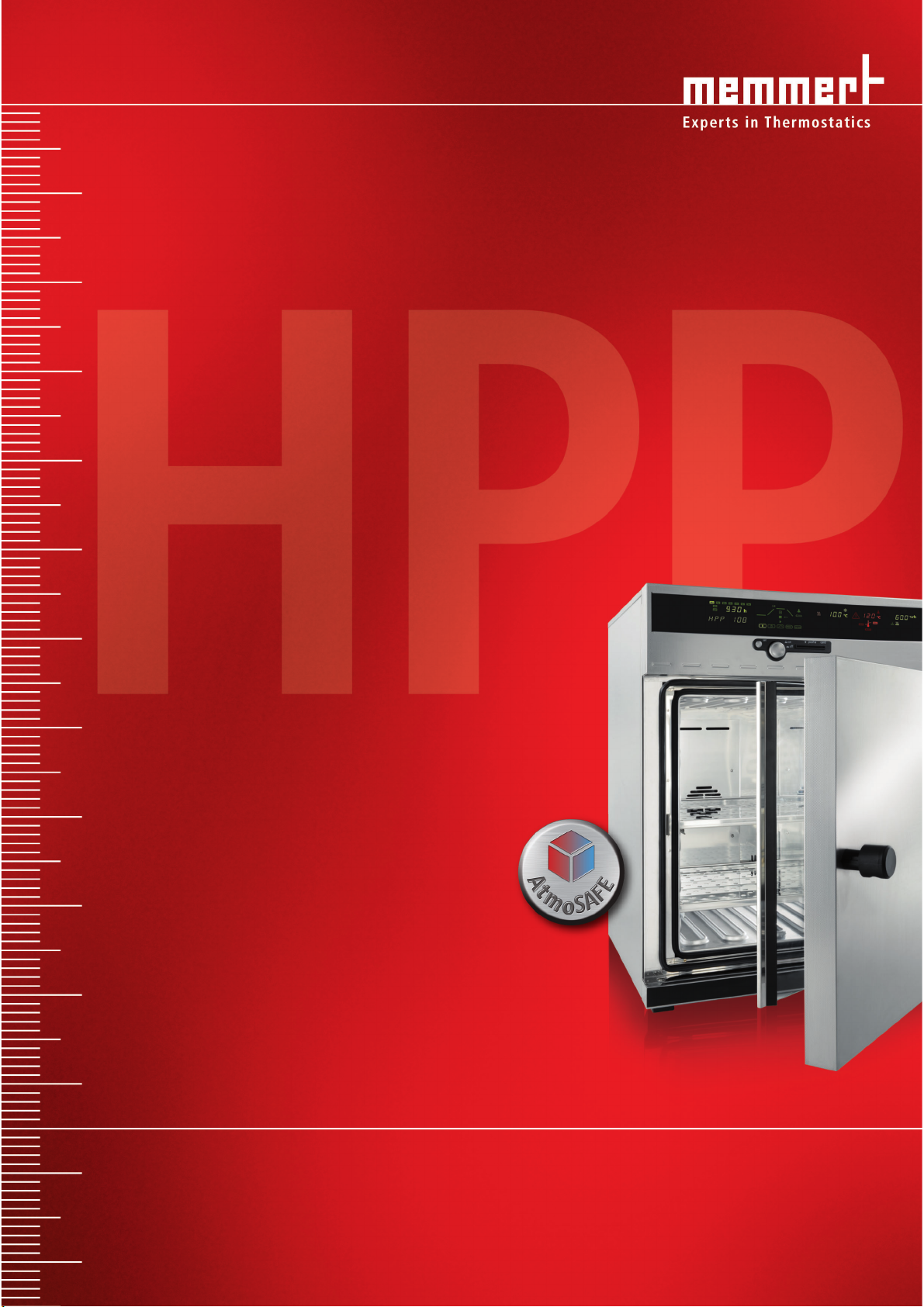
HPP 108/749
Constant climate chamber with Peltier cooling
Page 2

Manufacturer and customer service
MEMMERT GmbH + Co. KG
PO Box 17 20
91107 Schwabach, Germany
Äußere Rittersbacherstr. 38
91126 Schwabach
Germany
Phone: +49 (0) 09122 / 925-0
Fax: +49 (0) 09122 / 14585
E-mail: sales@memmert.com
Internet: www.memmert.com
Customer service:
Phone: +49 (0) 09122/925-128
and: +49 (0) 09122/925-126
E-mail: service@memmert.com
For service enquiries, please always specify the appliance number on the nameplate
(see page 14 ).
© 2011 Memmert GmbH + Co. KG
Date 02/2011
We reserve the right to make changes.
Page 3

About this manual
About this manual
Purpose and target group
This manual describes the setup, function, transport, operation and maintenance of constant
climate chambers of types HPP 108 and HPP 749. It is intended for use by accordingly trained
staff of the operator who are in charge of operating and / or maintaining the constant climate
chamber.
If you as the user intend to work with the constant climate chamber, you should read this
manual carefully before starting work with the unit. Familiarise yourself with the safety regulations. Only perform the work that is described in this manual. If there is something you do
not understand, or certain information is missing, ask your superior or get in touch with the
manufacturer. Do not do anything without authorisation.
Optional equipment
The constant climate chamber can be optionally equipped with an LED interior light to simulate daylight. In this manual, information related to this is marked with the word “optional”.
This means that this information is only relevant for appliances that include this function.
Other documents to be observed:
► for service and repair work (see page 57 ) – a separate service manual
► for controlling the constant climate chamber with the Memmert computer software “Cel-
sius” (see page 38 ) of the separate manual for this
► calibration documents
Storage and transfer
This instruction manual for the constant climate chamber should always be kept in a place
where those working with the constant climate chamber have access to it. It is the responsibility of the operator to ensure that persons who are working with or will work with the
constant climate chamber are informed as to the whereabouts of this instruction manual. We
recommend that it is always kept in a safe space close to the constant climate chamber. Make
sure that the instruction manual is not damaged by heat or humidity. If the constant climate
chamber is sold on or transported and then set up again at a different location, this instruction manual must also go with it.
3
Page 4

Content
Contents
1. Safety regulations 6
1.1 Terms and icons used .......................................................................................................... 6
1.1.1 Terms used .................................................................................................................... 6
1.1.2 Icons used ...................................................................................................................... 6
1.2 Product safety and dangers ................................................................................................ 7
1.3 Requirements of the operating personnel .......................................................................... 7
1.4 Responsibility of the owner ................................................................................................. 7
1.5 Changes and conversions ....................................................................................................8
1.6 Behaviour in case of malfunctions and irregularities ..........................................................8
1.7 Switching off the constant climate chamber in an emergency .......................................... 8
2. Design and description 9
2.1 Construction ........................................................................................................................ 9
2.2 Description .........................................................................................................................10
2.3 Working range ................................................................................................................... 10
2.4 Basic equipment ................................................................................................................ 11
2.5 Material.............................................................................................................................. 12
2.6 Intended use ...................................................................................................................... 12
2.7 EC declaration of conformity ............................................................................................13
2.8 Designation (nameplate) ................................................................................................... 14
2.9 Technical data .................................................................................................................... 14
2.10 Ambient conditions ........................................................................................................... 16
2.11 Electrical connection ..........................................................................................................16
2.12 Standard accessories ......................................................................................................... 16
3. Delivery, transport and setting up 17
3.1 Safety regulations .............................................................................................................. 17
3.2 Delivery .............................................................................................................................. 17
3.2.1 Unpacking ...................................................................................................................17
3.2.2 Checking for completeness and transport damage....................................................17
3.2.3 Disposal of packaging material ................................................................................... 17
3.3 Storage after delivery ........................................................................................................17
3.4 Setup.................................................................................................................................. 17
3.4.1 Setting up options .......................................................................................................19
4. Putting into operation 20
4.1 Checking ............................................................................................................................ 20
4.1.1 Check the door and adjust if necessary ......................................................................20
4.1.2 Checking the temperature sensor ...............................................................................20
4.2 Fill up and connect the water tank ...................................................................................20
4.3 Electrical connections ........................................................................................................ 21
4.4 Switching on ...................................................................................................................... 21
5. Operation and control 22
5.1 Operating personnel.......................................................................................................... 22
5.2 Opening the door .............................................................................................................. 22
5.3 Loading the constant climate chamber ............................................................................ 22
4
Page 5

Content
5.4 Basic information on operation ........................................................................................23
5.4.1 Switching appliance on and off .................................................................................. 23
5.4.2 User interface/controller ..............................................................................................23
5.4.3 Basic operation ............................................................................................................ 24
5.4.4 Setting parameters ...................................................................................................... 24
5.5 Operating modes ...............................................................................................................24
5.6 Operating mode settings ..................................................................................................25
5.6.1 Normal mode ..............................................................................................................25
5.6.2 Settings example normal mode .................................................................................. 26
5.6.3 Week time switch ........................................................................................................ 27
5.6.4 Settings example week time switch ............................................................................ 28
5.6.5 Programme mode ...................................................................................................... 29
5.6.6 Close statements for ramp segments .........................................................................32
5.6.7 Settings example programming mode ....................................................................... 34
5.6.8 Operation with computer/laptop (optional) ...............................................................38
5.7 Ending operation ............................................................................................................... 38
6. Malfunctions, warning and error messages 39
6.1 Warning messages temperature monitoring/humidification ........................................... 39
6.2 Power failure ......................................................................................................................40
7. Advanced functions 41
7.1 Printer ............................................................................................................................... 41
7.2 Basic appliance settings (Setup) ........................................................................................ 41
7.3 Temperature monitoring and safety equipment ...............................................................43
7.3.1 Electronic temperature monitoring (TWW) ................................................................44
7.3.2 Automatic temperature monitor (ASF) ...................................................................... 45
7.3.3 Warning messages ......................................................................................................46
7.4 Heat output distribution (BALANCE) ................................................................................. 47
7.5 Calibration ......................................................................................................................... 48
7.5.1 Temperature calibration ..............................................................................................48
7.5.2 Humidity calibration .................................................................................................... 49
7.6 Communication interfaces ................................................................................................ 50
7.6.1 USB interface .............................................................................................................50
7.6.2 Communication interfaces RS232/RS485 (optional) ................................................... 51
7.6.3 Connecting test chambers to a network with Ethernet interface .............................. 52
7.6.4 Log memory ...............................................................................................................52
7.6.5 Memory card MEMoryCard XL .................................................................................... 53
7.6.6 User ID card (optionally available as an accessory) ..................................................... 55
8. Maintenance and servicing 56
8.1 Cleaning .............................................................................................................................56
8.1.1 Cleaning the Peltier cooling modules ..........................................................................56
8.2 Regular maintenance.........................................................................................................56
8.3 Adjusting door ................................................................................................................... 57
8.4 Repairs and service ............................................................................................................57
9. Storage and disposal 58
9.1 Storage .............................................................................................................................. 58
9.2 Disposal ............................................................................................................................. 58
Index 59
5
Page 6
Safety regulations
1. Safety regulations
1.1 Terms and icons used
In this manual, certain common terms and icons are used to warn you of dangers or to give
you hints that are important in avoiding injury or damage. Observe and follow these hints and
regulations to avoid accidents and damage. These terms and icons are explained below.
1.1.1 Terms used
“Warning“ is always used whenever you or somebody else could be injured if you do
not observe the accompanying safety regulation.
“Caution” is used for information that is important for avoiding damage.
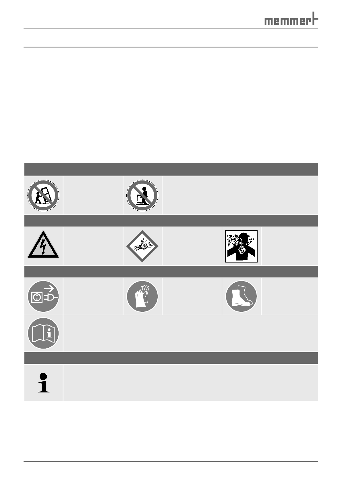
1.1.2 Icons used
Prohibition sign (forbidding an action)
Do not tilt
appliance
Warning icons (warning of a danger)
Danger of
electrical shock
Regulation signs (stipulate an action)
Disconnect the
mains plug
Observe information in separate manual
Other icons
Do not lift appliance without assistance
Explosive
atmosphere
Wear gloves
Dangerous
gases/vapours
Wear safety
shoes
Important or useful additional information
6
Page 7
Safety regulations
1.2 Product safety and dangers
Constant climate chambers of types HPP 108 and HPP 749 are technically well-developed,
manufactured using high-quality materials and are tested for many hours in the factory. They
contain the latest technology and comply with recognised technical safety regulations. But
there are still dangers involved, even when the appliance is used as intended. These dangers
are described below.
Warning!
After removing covers, live parts may be exposed. You may receive
an electric shock if you touch these parts. Disconnect the mains plug
before removing any covers. Any work inside the unit may only be
performed by qualified electricians.
Warning!
When loading the chamber with an unsuitable load, poisonous or
explosive vapours or gases may be produced. This could cause the
chamber to explode and people could be badly injured or poisoned.
The chamber may only be loaded with materials/test objects which
do not form any poisonous or explosive vapours when heated up
(see also chapter Intended use on page 12 ).
1.3 Requirements of the operating personnel
The constant climate chamber may only be operated and maintained by persons who are of
legal age and who have received instructions for the constant climate chamber. Personnel
who are to be trained, instructed or who are undergoing general training may only work on
the constant climate chamber under the continuous supervision of an experienced person.
Repairs may only be performed by qualified electricians. In this case, the regulations in the
separate service manual must be observed.
1.4 Responsibility of the owner
The owner of the constant climate chamber
► is responsible for the flawless condition of the constant climate chamber and for the con-
stant climate chamber being operated in accordance with its intended use (see page 12);
► is responsible for ensuring that persons who are to operate or service the constant climate
chamber are qualified to do this, have received instructions about the constant climate
chamber and are familiar with this operating manual;
► must know about the applicable regulations, requirements and work protection regula-
tions and train staff acordingly;
► is responsible for ensuring that unauthorised persons have no access to the constant
climate chamber;
► is responsible for ensurting that the maintenance plan is adhered to and that maintenance
work is properly carried out (see page 56 );
► ensures, for example through corresponding instructions and inspections, that the con-
stant climate chamber and its surroundings are kept clean and tidy;
► is responsible for ensuring that personal protective clothing is worn by operating person-
nel, e.g. work clothes, safety shoes, protective gloves.
7
Page 8
Safety regulations
1.5 Changes and conversions
No independent conversions or alterations may be made to the constant climate chamber. No
parts may be added or inserted which have not been approved by the manufacturer.
Independent conversions or alterations result in the EC declaration of conformity (see page
13 ) losing its validity, and the constant climate chamber may no longer be operated.
The manufaturer is not liable for any damage, danger or injuries that result from independent
conversions or alterations, or from non-observation of the regulations in this manual.
1.6 Behaviour in case of malfunctions and irregularities
The constant climate chamber may only be used when in a flawless condition. If you as the
opertor notice irregularities, malfunctions or damage, immediately put the constant climate
chamber out of service and inform your superiors.
You can find information on eliminating malfunctions from page 39 .
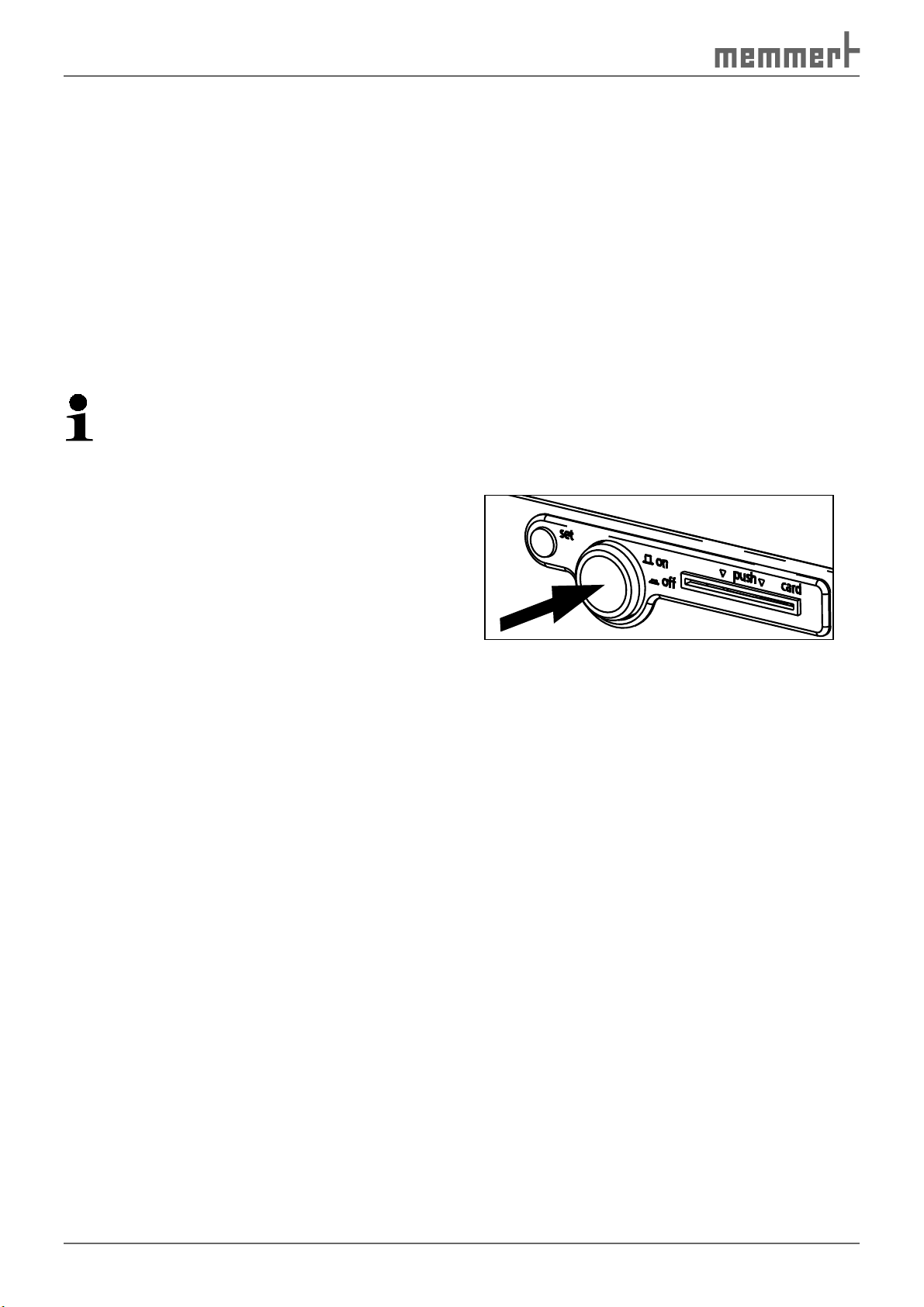
1.7 Switching off the constant climate chamber in an emergency
Push main switch on front side of
appliance ( Fig. 1 ). This causes the constant
climate chamber to switch off.
Fig. 1
Switch off constant climate chamber by
pressing main switch
8
Page 9
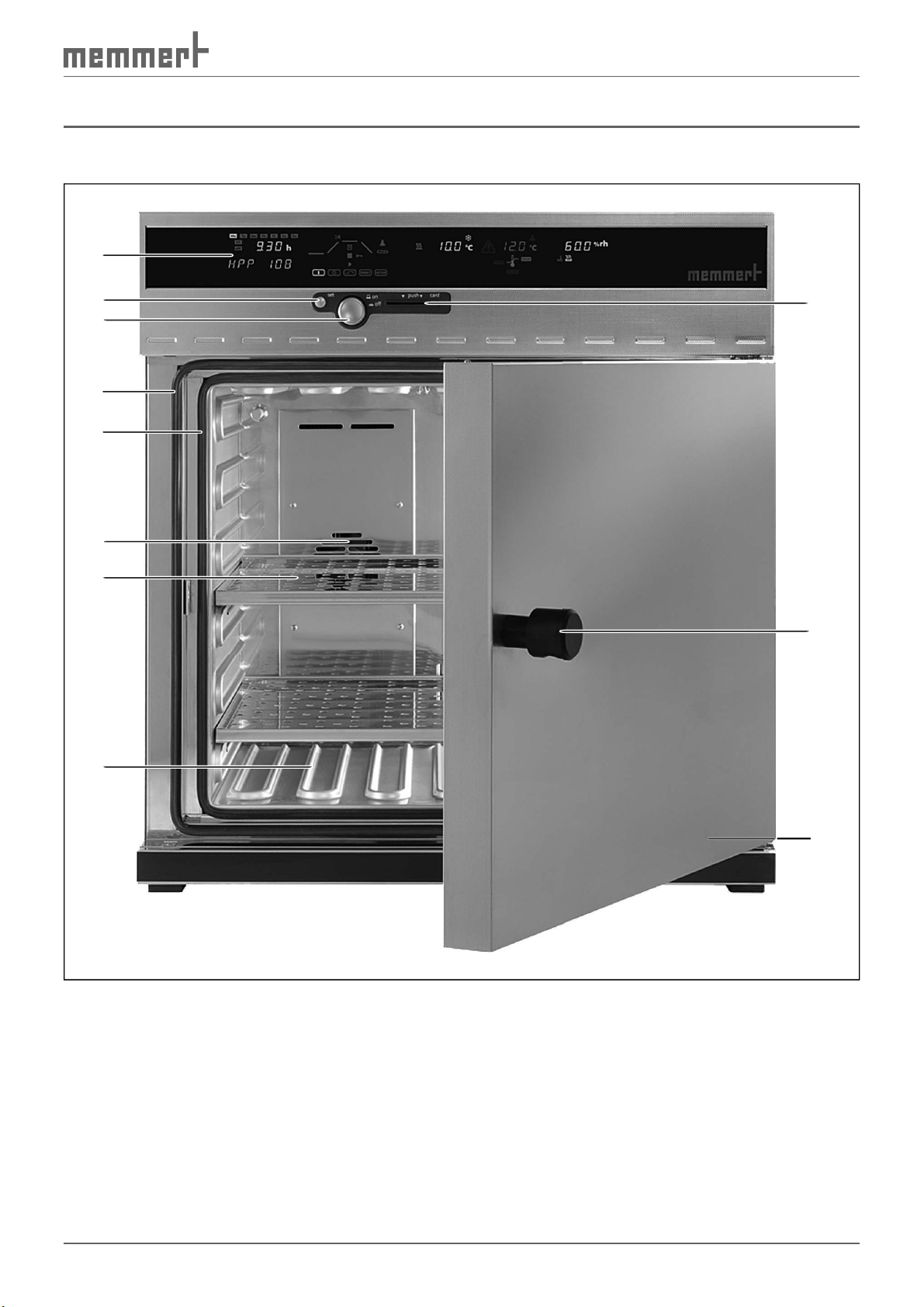
2. Design and description
2.1 Construction
1
Design and description
2
3
4
5
6
7
11
10
8
Fig. 2 HPP Constant climate chamber
1 Controller/user interface (see page 23 )
2 Set key
3 Main switch / push-turn control (see page 23 )
4 Door seal
5 Interior seal
6 Chamber fan
7 Sliding shelf
8 Heating ribs
9 Nameplate (underneath door)
10 Door knob
11 Card reader
9
9
Page 10
Design and description
2.2 Description
The constant climate chamber can heat the interior up to 70 ºC and cool it down to 5ºC. For
this purpose, low-noise, long-life and energy-saving Peltier cooling and heating technology is
used. In heating operation, a part of the required energy is extracted from the surroundings
(heat pump principle).
Humidity in the interior can be regulated between 10 and 90 % rh (rh = relative humidity).
The humidity is increased by water from a tank being evaporated and fed into the interior,
and is reduced through condensation on a Peltier module.
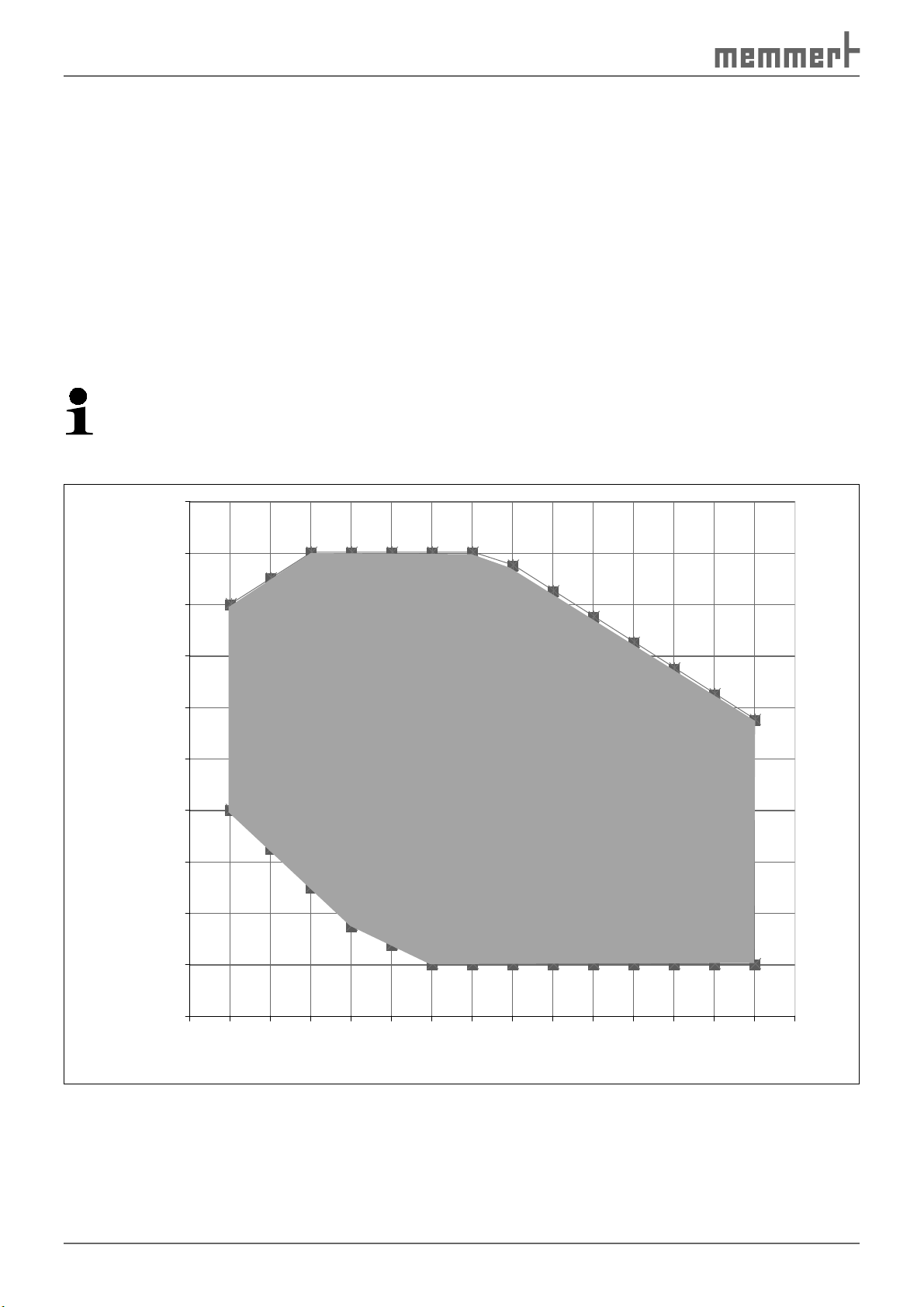
2.3 Working range
The temperature-humidity diagram ( Fig. 3 ) specifies at what range of temperature and humidity a permanent, condensation-free operation is possible.
Caution:
If the appliance is in operation at the upper level or outside the working range for long
periods, puddles of water may form inside the chamber and water may force its way out
of the door seal.
100
90
80
70
60
50
Humidity % rH
40
30
20
10
C
B
A
0
0 5 10 15 20 25 30 35 40 45 50 55 60 65 70 75
Fig. 3 Temperature-humidity working range
10
Temperature °C
Page 11

Design and description
Range A:
In this range, temperature and humidity can be combined as you please, without resulting in
any significant condensation. If there are extreme ambient conditions, the working range may
be restricted.
Range B:
If the specified range is exceeded upwards, e.g. 80 % rh at 60°C, the hot steam fed in will immediately condense, due to the dew-point, at the coldest point in the appliance.
Range C:
At low temperatures and low relative air humidity, the effective range is heavily dependent on
the degree of humidity of the chamber load.
2.4 Basic equipment
► Low-noise, long-life and energy-saving Peltier cooling and heating technology (in heat-
ing mode, part of the energy required is extracted from the surroundings = heat pump
principle)
► Electronic fuzzy-supported PID process controller with permanent performance adjust-
ments and time-saving self-diagnosis system to quickly locate errors (see pages 38 and 45)
► Alphanumeric text display
► Control of the appliance and logging the actual values with a preformatted empty
MEMoryCard XL (storage capacity 32 kByte, reprogrammable for up to 40 ramp segments
and in addition 135 hours of log memory for temperature and humidity with a scanning
interval of 1 minute)
► Programme sequence control for up to 40 ramp segments
► Integrated week time switch with group function (e.g. all working days)
► Retracting push-turn control for simple operation
► Optical alarm display
► Integrated horn as alarm if limit values are crossed, as acoustic signal when programme
ends and to confirm input (button click)
► Digital monitoring control for overtemperature, undertemperature and automatic tem-
perature monitor (ASF)
► Two separate Pt100 temperature sensors DIN class A in a 4-wire circuit for control and
monitoring
► Parallel printer port (PCL3-compatible)
► USB interface for computer-based temperature control programmes and to read out the
controller’s internal log memory
► MEMMERT software "Celsius" for remote control of the chamber via computer (see page
37) and to read out the internal controller log memory
► As an optional accessory, external card reader for MEMory-Card XL for connection to the
PC-USB interface, printer cable (parallel, shielded)- 25-pin
► Language setting (German, English, French, Spanish, Italian)
► Capacitive humidity sensor
► Active humidity control guarantees that setpoint humidity is quickly achieved, with short
recovery times, and avoiding condensation formation
11
Page 12

Design and description
► 7 different ramp close statements for sophisticated temperature-control tasks
► Acoustic and visual signals if temperature or humidity limits are crossed, and if water tank
is empty
► Internal log memory with 1024 kB as a ring memory for all temperature and humidity
values, errors and settings with realtime and date, logging for approx. 3 months with a
1-minute logging interval
► Calibration possible without separate computer: 3-point calibration on controller for tem-
perature and 2-point calibration for humidity at 20 % rh and 90 % rh
► LED interior light ( light panels) in various light colours (optional)
2.5 Material
For the outer housing, MEMMERT uses stainless steel (W.St.No. 1.4016 = ASTM 430), for the
interior, stainless steel (W.St.No. 1.4301= ASTM 304) is used, which stands out through its
high stability, optimal hygienic properties and corrosion-resistance towards many (but not all!)
chemical compounds (caution for example with chlorine compounds).
The chamber load for the appliance must be carefully checked with respect to chemical compatibility with the materials mentioned.
A resistance table for all these materials can be requested from the MEMMERT.
2.6 Intended use
Constant climate chambers HPP may be used exclusively for temperature and climate testing
of materials and substances in the context of the procedures and specifications described in
this manual. Any other use is improper, and may result in hazards and damage.
The test chambers are not explosion-proof (they do not comply with workplace health &
safety regulation VBG 24). The chambers may only be loaded with materials and substances
which cannot produce any toxic or explosive vapours at temperature ranges up to 70 ºC, and
which themselves cannot explode, burst or ignite.
The test chambers may not be used for drying, vaporising and branding paints or similar materials, the solvents of which could form an explosive mixture when combined with air. If there
is any doubt as to the composition of materials, they must not be loaded into the constant
climate chamber. Potentially explosive gas-air mixtures must not be produced, either in the
interior of the chamber or in the direct vicinity of the appliance.
12
Page 13
Design and description
2.7 EC declaration of conformity
EC Declaration of Conformity
Manufacturer´s name and address: MEMMERT GmbH + Co. KG
Äußere Rittersbacher Straße 38
D-91126 Schwabach
Product: Constant-Climate-Chamber
Type: HPP …
Sizes:
Nominal voltage:
The designated product is in conformity with the European EMC-Directive
Council Directive of 03 May 1989 on the approximation of the laws of the Member States relating to
electromagnetic compatibility.
Full compliance with the standards listed below proves the conformity of the designated product with the essential
protection requirements of the above-mentioned EC Directive:
DIN EN 61326-1:2006-10 EN 61326-1:2006
DIN EN 61000-3-11:2001-04 EN 61000-3-11 :2000
The designated product is in conformity with the European Low Voltage Directive
Council Directive on the approximation of the laws of the Member States relating to Electrical
equipment for use within certain voltage limits.
Full compliance with the standards listed below proves the conformity of the designated product with the essential
protection requirements of the above-mentioned EC Directive:
DIN EN 61 010-1 (VDE 0411 part 1):2002-08 EN 61 010-1:2001
DIN EN 61 010-2-010 (VDE 0411 part 2-010):2004-06 EN 61 010-2-010:2003
Schwabach, 23.07.08
______________________________
(Legally binding signature of the issuer)
This declaration certifies compliance with the above mentioned directives but does not include a property assurance. The
safety note given in the product documentation which are part of the supply, must be observed.
AC 230 V 50 / 60Hz
alternative AC 115 V 50/60 Hz
2004/108/EEC
including amendments
2006/95/EEC
including amendments
Modelljahr 2003 D10633 / 23.07.08
13
Page 14
Design and description
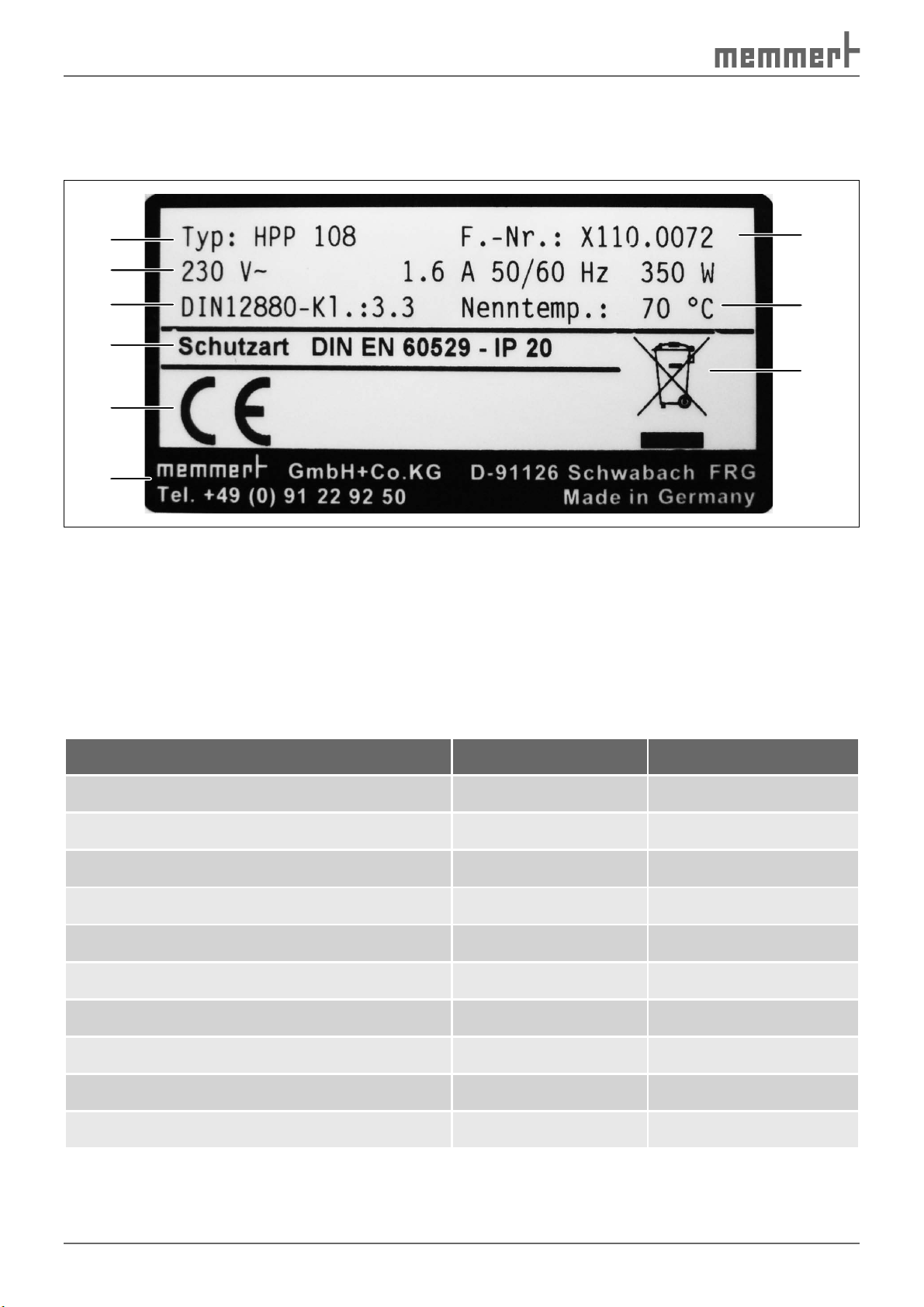
2.8 Designation ( nameplate)
The nameplate provides information about the appliance model, manufacturer and technical
data. It is attached to the front of the appliance, on the right beneath the door (see page 9 ).
1
2
3
4
5
6
Fig. 4 Nameplate
1 Type designation
2 Connection values
3 Applied standard
4 Protection type
5 CE conformity
9
8
7
6 Address of manufacturer
7 Disposal note
8 Nominal temperature range
9 Factory number
2.9 Technical data
Model HPP 108 HPP 746
Chamber width A* [mm]
Chamber height B* [mm]
Chamber depth C* [mm]
Appliance width D* [mm]
Appliance depth F* [mm]
Appliance height E* [mm]
Chamber volume [litres]
Weight [kg]
Performance [W]
Max. number of sliding shelves
560 1040
480 1200
400 600
710 1190
640 825
760 1620
108 749
66/70 218/278
350 1050
514
* see Fig. 5 on page 16 .
14
Page 15

Design and description
Model HPP 108 HPP 746
Max. load per sliding shelf [kg] 30 30
Max. load per appliance [kg]
60 160
Electrical equipment
Operating voltage
Current consumption
Protection class
Protection type
Interference-suppressed
Fuses Appliance: 250 V/15 A (appliance)
Temperature
see nameplate
see nameplate
1 (acc. to EN 61010)
IP 20 (EN 60529)
Class B acc. to EN 55011
Controller: 100 mA (230 V) or 200 mA (115
V)
► Temperature recording: Pt100 in a 4-wire
circuit
► Adjustment range: 0 °C to 70 °C
Adjustment precision: 0.1 °C
► Working temperature range: 5 °C to 70 °C
► Temperature variation (time): ±0.1 °C
► Spatial deviation: max. ±0.3 °C bei 37°
Monitoring
► Temperature recording: Pt100 in a 4-wire
circuit
► Settings range -5 °C to +75 °C
► Adjustment precision: 0.1 °C
Humidity The relative humidity in the chamber is
measured by a capacitive humidity sensor and
displayed digitally in percent
► Measurement precision of the humidity
sensor: 0.5 % rh
► Adjustment range: 10 bis 90 % rh, off*
► Adjustment precision: 1 % rh
► Display range: 1 bis 98 % rh
► Temperature variation (time): max. ±1.5
% rh
* Setting off: Humidity control disabled
* see Fig. 5 on page 16 .
15
Page 16
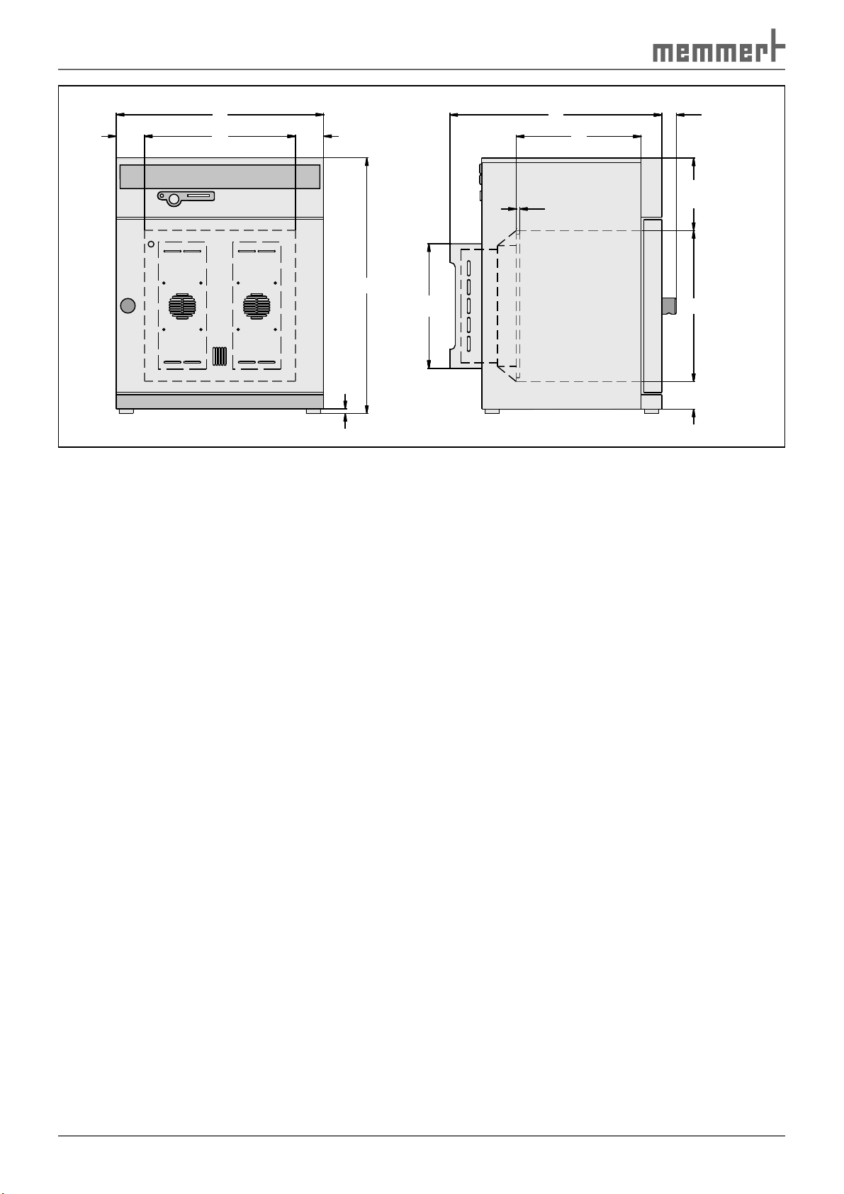
Design and description
D
A75 75
E
302
12
Fig. 5 Dimensions of constant climate chambers HPP
2.10 Ambient conditions
38F
C
10
B 19771
► The constant climate chamber may only be used in enclosed rooms and under the follow-
ing environmental conditions:
Ambient temperature: 16 ºC to 28ºC
Humidity: max. 70 % not condensing
Degree of pollution: 2
Altitude of installation: max. 2,000 m above sea level
► The constant climate chamber may not be used in areas where there is a risk of explosions.
The ambient air must not contain any explosive dusts, gases, vapours or gas-air mixtures.
The constant climate chamber is not explosion-proof.
► Heavy dust production or aggressive vapours in the vicinity of the appliance could lead to
sedimentation in the chamber interior and as a consequence, could result in short circuits
or damage to electrical parts. For this reason, sufficient measures should be taken to prevent large clouds of dust or aggressive vapours from developing.
2.11 Electrical connection
Observe the country-specific regulations when making connections (e.g. in Germany
DIN VDE 0100 with residual current device).
This appliance is intended for operation on an electrical power system with a system impedance Z
must ensure that the constant climate chamber is operated only on an electrical power system
that meets these requirements. You can ask your local energy supply company what the system impedance is.
at the point of transfer (service line) of a maximum of 0.292 ohm. The operator
max
2.12 Standard accessories
► Sliding shelf
► Water tank with connection hose
16
Page 17

Delivery, Transport and Setting Up
3. Delivery, transport and setting up
3.1 Safety regulations
Warning!
You may get your hands or feet squashed when transporting and installing the constant climate chamber. You should
wear protective gloves and work shoes.
Warning!
Because of the weight of the constant climate chamber, you could
cause yourself an injury if you try to lift it. At least two people are
needed to carry the constant climate chamber HPP 108, and four for
the constant climate chamber HPP 749.
Warning!
The constant climate chamber could fall over and seriously injure
you. Never tilt the constant climate chamber and only transport it in
an upright position.
3.2 Delivery
The constant climate chamber can be packaged in cardboard or in a box, and is delivered on a
wooden pallet.
3.2.1 Unpacking
Remove the cardboard packaging by pulling upwards or cutting carefully along an edge.
3.2.2 Checking for completeness and transport damage
► Check the delivery note to ensure that the delivery is complete.
► Check the constant climate chamber for damage.
If you notice deviations from the delivery note, damage or irregularities, do not put the
constant climate chamber into operation, but inform the haulage company and the manufacturer.
3.2.3 Disposal of packaging material
Dispose of the packaging material (cardboard, wood) in accordance with the appropriate
regulations for the material in your country.
3.3 Storage after delivery
If the constant climate chamber is initially to be stored after delivery: Read the storage conditions from page 58 .
3.4 Setup
The installation site must be flat and horizontal and must be able to reliably bear the weight
of the constant climate chamber (see chapter Technical data on page 14 ). Do not place the
appliance on a flammable surface.
An 230 V/16 A/115 V power connection (see nameplate) must be available at the installation
site.
17
Page 18
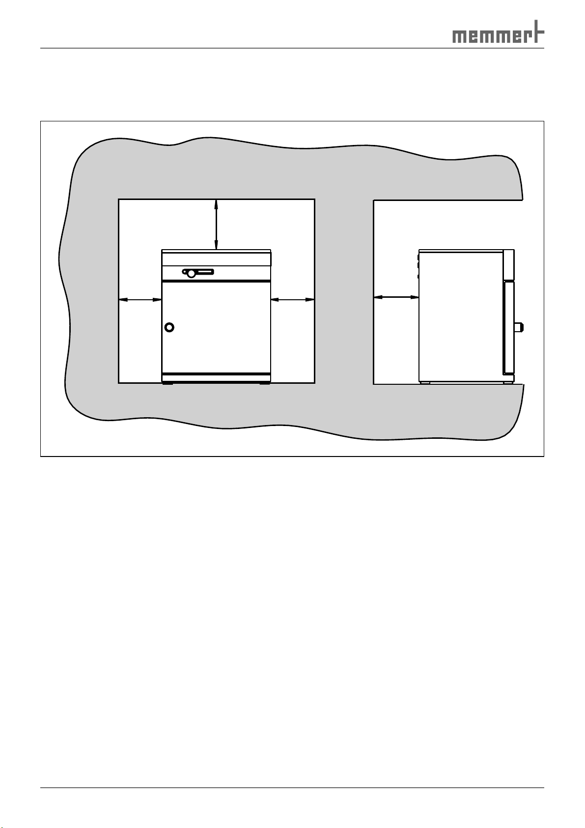
Delivery, Transport and Setting Up
The distance between the wall and the rear of the chamber must be at least 15 cm. The clearance from the ceiling must not be less than 20 cm and the side clearance from the wall must
not be less than 8 cm ( Fig. 6
). Sufficient air circulation in the vicinity of the chamber must be
guaranteed at all times.
FP
FP
FP
Fig. 6 Minimum clearance from walls and ceiling
FP
18
Page 19

Delivery, Transport and Setting Up
3.4.1 Setting up options
Read the assembly instructions for the respective accessory part.
Floor/table
The chambers may be placed on the floor. Constant climate chambers HPP 108 may be placed
on a table (work surface), if the table is flat and horizontal and able to bear the weight of the
constant climate chamber.
Base
The chamber can be placed on a base (available as an accessory) ( Fig. 7 ).
Stackable model (HPP 108 only)
Two constant climate chambers HPP 108 can be placed on top of one another. Please ensure
that the chamber with the lower working temperature is always used as the lower chamber:
Warning!
Danger through contact with electrical voltage. Remove the
mains plug if the chamber is already connected to the power
supply.
1. Remove the housing cover from the lower chamber.
2. Insert the drilling template (supplied with the foot alignment) into the overturned lid.
3. Mark the drilling point and drill with a 4.2 mm diameter drill bit.
4. Screw the foot alignments to the top of the lid with the screws and nuts supplied ( Fig. 8 ).
5. Put the covers back on.
Fig. 7
Base
Fig. 8
Attaching the foot alignments when two
chambers are placed on top of one another
19
Page 20

Putting into Operation
4. Putting into operation
4.1 Checking
4.1.1 Check the door and adjust if necessary
The door may have been twisted during transport. You should therefore check whether the
door closes properly and the seals are in the correct position. Adjust door if necessary (description on page 57 ).
4.1.2 Checking the temperature sensor
Due to strong vibrations during transport,
the temperature sensors could have moved
out of position in their holders in the
ceiling of the working chamber.
Before operating for the first time, check
the temperature sensor for its correct positioning and if necessary adjust its position
in the holder ( Fig. 9 ). Open the door to do
this (see page 22 )
Fig. 9 Temperature sensor on the ceiling of
the interior
4.2 Fill up and connect the water tank
Fill the water tank supplied with water and connect it with the
enclosed tube to the "H2O" connection on the rear of the
chamber ( Fig. 10 ).
Water specification
To generate steam, only either
► steam-distilled water (aqua dest) may be used
or
► demineralised/desalinated water (aqua dem) in accord-
ance with VDE 0510/DIN EN 50272, provided the regulations are strictly maintained (conductivityof production
≤ 10 μS/cm). Battery water inaccorance with VDE 0510
can be obtained in all large chemist's, supermarkets, DIY
stores and wholesalers. VDE 0510/DIN EN 50272 must
be explicitly marked on the label.
Otherwise, limescale in the steam generators, steam piping
and tube pumps may impair the the functionality of the
appliance.
The water used must have a pH value of > 5 and < 7.
Fig. 10 Water connection
20
Page 21

Putting into Operation
4.3 Electrical connections
Caution:
Observe the country-specific regulations when making connections (e.g. in Germany
DIN VDE 0100 with residual current device (RCD)). Remember the connected loads and
power values (see nameplate and also chapter " Technical data " on page 14 ).
The constant climate chamber is intended for operation on an electrical power system with
a system impedance Z
The operator must ensure that the constant climate chamber is operated only on an electrical
power system that meets these requirements. If necessary, you can ask your local energy supply company what the system impedance is.
Only appliances may be connected to external connections whose interfaces comply with the
requirements for safety extra-low voltage (e.g. computer, printer).
at the point of transfer (service line) of a maximum of 0.292 ohm.
max
4.4 Switching on
To switch on the appliance, press the main
switch on the front of the appliance ( Fig. 11 ).
Caution:
The first time the appliance is operated, it must not be left unattended
until it has reached the steady state.
Fig. 11 Switching on the constant climate
chamber
21
Page 22

Operation and control
5. Operation and control
5.1 Operating personnel
The constant climate chamber may only be operated by persons who are of legal age, and
who have received instructions for the constant climate chamber. Personnel who are to be
trained, instructed or who are undergoing general training may only work with the constant
climate chamber under the continuous supervision of an experienced person.
5.2 Opening the door
► To open the door, turn the handle to the right ( Fig. 12 ).
► To close, press in the door knob.
5.3 Loading the constant climate chamber
Warning
When loading the chamber with an
unsuitable load, poisonous or explosive
vapours or gases may be produced. This
could cause the chamber to explode, and
people could be badly injured or poisoned. The chamber may only be loaded with materials/test objects
which do not form any toxic or explosive vapours when heated up
and cannot ignite (see also chapter " Intended use " on page 12 ). If
there is any doubt as to the composition of materials, they must not
be loaded into the constant climate chamber.
Caution:
Check the chamber load for chemical compatibility with the materials of the constant
climate chamber (see page 12 ).
Replacing sliding shelf/shelves. The maximum quantity, and load capacity of the sliding shelves
can be found in table in chapter " Technical data " on page 14 .
The chamber must not be
loaded too tightly, so that
proper air circulation in the
working chamber is guaranteed. Do not place any of the
chamber load on the floor,
touching the side walls or
right below the ceiling of the
working chamber ( Fig. 13 , see
also the "correct loading"
sticker on the appliance).
close
open
Fig. 12 Opening and closing the door
If the load is unfavourable
(too close together) it may
take longer than normal to
reach the set temperature
under some circumstances.
22
Fig. 13 Correct placement of the chamber load
Page 23

Operation and control
N
5.4 Basic information on operation
5.4.1 Switching appliance on and off
The constant climate chamber is switched on and off by pressing the main switch / push-turn
control on the front of the appliance:
► Switching on: press the main switch so that it comes out of the appliance ( Fig. 14 ).
► Switching off: press the main switch so that it retracts back into the appliance ( Fig. 15 ).
Fig. 14 Switching on the constant climate
chamber
Fig. 15 Switching off the constant climate
chamber
5.4.2 User interface/ controller
In normal and programme modes, the desired parameters are entered on the operating panel
of the controller on the front of the appliance ( Fig. 16 ). Basic settings, as well as those for time
and printing, can also be made here. In addition, programmed and current parameters are
displayed, as well as warning messages:
12435678910
IN 1
OUT
IN 2
rh
%
mb
card
DEFROSTERI
°C
MIN
°C
MAX
AUTO
Tu
Mo
We
on
off
Sa Su
Fr
Th
h
t1
set
t3
t2
t4
PRINT
on
off
SETUP
4
3
loop
2
1
push
IN 1
I
Fig. 16 Operating panel
1 Time display
2 Programme mode display (see page 29 )
3 Interior lighting active (optional)
4 Display: Appliance locked with user-ID
card (see page 55 )
5 Display: appliance is heating up
6 Temperature display
7 Display: appliance is cooling down
8 Temperature monitoring warning (see
page 43 )
9 Temperature monitoring (see page 43 )
1315161718
111214
10 Humidity display
11 Display: Appliance is humidified
12 Warning: Water tank empty
13 Interior light (optional)
14 Chipcard reader
15 Operating mode display (see page 24 )
16 Main switch /push-turn control
17 Set key
18 Alphanumeric text display for error and
status messages
23
Page 24

Operation and control
5.4.3 Basic operation
set
set
All settings are selected by turning the push/turn control to the left or right ...
...and adjusted by turning it with the SET key held down.
5.4.4 Setting parameters
Normally, all setting actions on the operating panel described on the following pages are
made in the same way:
set
set
set
1. Select the desired parameter with the push/turn control (menu item, e.g.
temperature); then all other parameters go dark and the selected one flashes.
2. With the SET key held down, set the desired value (e.g. 58.0°C) with the push/
turn control.
3. Release the SET key, and the programme is started. The display briefly shows
the value set, flashing. Then the current temperature is displayed and the
constant climate chamber begins to heat up or cool down to the set temperature.
4. Settings for other parameters are made in the same way.
The control returns automatically to the main menu if the push/turn key or SET key is not
used for approx. 30 seconds.
5.5 Operating modes
Constant climate chambers HPP can be operated in four different ways:
► Normal mode: The constant climate chamber runs in permanent operation at the temper-
ature and humidity values set on the operating panel. Operation in this mode is described
from page 25 .
► Week time switch: The constant climate chamber runs at the set values only at certain
times. Operation in this mode is described from page 27 .
► Programme mode: Time sequences of temperature and humidity and fan values are
programmed (so-called ramps), which the test chamber automatically works through one
after another. Operation in this mode is described from page 29 .
► Interface mode with computer/laptop (optional, see page 38 ).
PRINT
SETUP
Normal mode
(see page 25 )
Fig. 17 Operating modes
24
Week time
switch
(see page 27 )
Programme
mode
(see page 29 )
Printer
(see page 41 )
Basic appliance
settings
(see page 41 )
Page 25

Operation and control
5.6 Operating mode settings
1. Switch on the appliance by pressing the main switch (main switch comes out of appliance,
see page 23 ).
set
2. Keep the SET key depressed for approx. three seconds and the selected mode
starts flashing.
3. Select the desired operating mode/function (normal mode, week time switch,
set
programming mode, printer or basic appliance settings) by turning control
with SET key held down.
set
4. Release the SET key, and the selected operating mode is saved.
5.6.1 Normal mode
In this operating mode, the constant climate chamber runs in permanent operation at the
values set on the operating panel (see above). Example of settings: See next chapter 5.6.2 .
1. Load the constant climate chamber (see page 22 ).
2. Switch on appliance. To do this, press the push-turn control on the operating panel so that
it comes out of the appliance (see page 23 ).
3. Select the normal operating mode
with the push/turn control:
PRINT
SETUP
4. As described above, set the individual parameters with the push-turn control and the SET
key:
Temperature setpoint
Adjustment range: 0°C to 70°C
Interior light (optional)
t2
°C
Adjustment range: 0 % to 100 % in steps of
10%
The interior lighting can only be activated at a working temperature of up
to 40 ºC.
Temperature monitoring
Adjustment range:
MIN MAX AUTO
°C
(see also page 43 )
MIN
AUTO
MAX
Humidity setpoint
rh
Adjustment range: 10 to 90 %rh,
%
off
Not all combinations of temperature and humidity are possible (see also page 10 ).
25
Page 26

Operation and control
5.6.2 Settings example normal mode
At a humidity of 70 % rh and 60 % light intensity (optional), the climate chamber should heat
up to 37 °C ( Fig. 18 ).
100 %
70 °C
60 °C
40 °C
20 °C
t
80 %
60 %
40 %
20 %
t
Fig. 18 Example for normal mode
1. Setting the normal operating mode:
Keep the SET key depressed for approx. 3 seconds and the current operating mode then begins to flash.
Select the operating mode
with the push-turn control,
while the SET key is held down. After you let go of the SET
key, the control is in the normal operating mode.
2. Setting the temperature setpoint:
Hold down the SET key and set the desired temperature set-
point of 37.0 °C with the push-turn control.
100 %
80 %
60 %
40 %
20 %
PRINT
°C
t
SETUP
Release the SET key; the appliance will briefly flash, showing the
temperature setpoint. Then the current temperature appears
on the display and the controller begins to move to the set
temperature of 37.0 °C.
► Heating up is indicated by the icon.
► Cooling down is indicated by the green cooling symbol .
3. Adjusting the light intensity (optional):
Turn the push-turn control to the right until the lighting display
flashes. With the SET key held down, set the light intensity to
60 % with the push-turn control (six bars light up). Release the
SET key. The interior light is now at 60 % intensity.
4. Setting the monitoring temperature:
Turn the push-turn control to the right until the monitoring
temperature and the MIN- or MAX-icon flashes. Hold down
the SET key and with the push-turn control set the overtemperature limit to 38.5 °C and the undertemperature limit to
35.5 °C. Turn the push-turn control to the right until the monitoring temperature and the AUTO icons flash. Hold down the
SET key and set to on with the push-turn control.
°C
MAX
MIN
AUTO
The tolerance band is set in the SETUP menu (see page
42 ).
26
Page 27

5. Setting the humidity setpoint:
Turn the push-turn control to the right until the humidity
display flashes. Hold down the SET key and set the desired
humidity setpoint of 70.0 % rh with the push-turn control. After
releasing the SET key the humidity setpoint briefly flashes. Then
the current humidity value appears on the display and the controller begins to move to the set value.
Operation and control
rh
%
The humidification process is indicated by the
symbol.
The constant climate chamber is now running in permanent operation with the set values.
5.6.3 Week time switch
In this operating mode, the week time switch is active
and the constant climate chamber switches on and
PRINT
off at the time programmed.
During the OFF phase of the week time switch, the constant climate chamber is in standby
mode. The heating and cooling functions are switched off and the controller display shows
the time, dimmed. During the ON phase, the constant climate chamber works with the set
values for temperature and humidity.
The sequence of the week time switch repeats itself each week.
In total, a maximum of nine time blocks can be programmed,
consisting of the switching on and switching off times:
Mo
on
off
Tu
We
Th
By turning the push/turn control, the following parameters
can be selected and altered, as described in the chapter
" Basic information on operation " on page 23 :
SETUP
Fr
Sa
h
Su
Weekday
Adjustment range: Monday to Sunday
Day groups
Adjustment range: Working days Mo–Fr
Weekend Sat–Sun
No switch on time: ---Appliance not switched on on this day
Switch on time (on)
Adjustment range: 00:00 to 23:59 hours
Switch off time (off)
Adjustment range: One minute beyond the
switch on time up to 24:00
Mo
Mo
Mo
on
off
on
off
on
off
Tu
Tu
Tu
We
We
We
Th
Th
Th
Fr
Fr
Fr
h
h
Sa
Sa
Sa
Su
Su
Su
27
Page 28

Operation and control
By turning further to the right, parameters (temperature setpoint etc.) can be selected as in
the normal operating mode.
If no settings (temperature setpoint etc.) are made for the ON phase, the values from the
normal operating mode are used by the controller.
For reasons of safety, you should always check that only one switch on time is programmed in
the desired time blocks and days.
Direct setting of the temperature setpoint:
If the controller is in standby mode or the week time switch is in the ON phase, the temperature setpoint can be directly accessed by briefly pressing the SET key. By turning the control
to the right, you are returned to temperature monitoring and humidity. By turning to the left,
you come back to the settings for the individual time blocks.
5.6.4 Settings example week time switch
The constant climate chamber should be switched on at 07.30 from Monday to Friday (working day group) and switched off at 18.00. In addition, it should operate on Saturdays from
10.00 to 14.00 ( Fig. 19 ).
Mo
Fig. 19 Operation with week time switch (example)
1. Setting the week time switch operating mode
Hold the SET key down for approx. three seconds; the
current operating mode then begins to flash. Select the
week time switch operating mode with the push-turn
control, while the SET key is held down.
Release the SET key, the control is now in the week time
switch operating mode.
28
Tu
We
Thu
Fr
Sa
Su
PRINT
SETUP
Page 29

Operation and control
2. Switch on Mo-Fr at 07.30
Turning the push/turn control to the left and select “Mo-
Fr on“ (group working days).
Hold down the SET key and set the desired switch-on
time with the push/turn switch to 7:30.
3. Switch off Mo–Fr at 18.00
Select “Mo–Fr off“ (group working days) with the push/
turn control.
Hold down the SET key and set the desired switch-off
time with the push/turn switch to 18:00.
4. Switch on Saturday at 10:00
With the push/turn control, select the “Sat on” icon.
Hold down the SET key and set the desired switch-on
time with the push-turn switch to 10:00.
Mo
Mo
Mo
on
off
on
off
on
off
Tu
We
Th
Fr
Sa
Su
h
Tu
We
Th
Fr
Sa
Su
h
Tu
We
Th
Sa
Su
Fr
h
5. Switch off on Sa at 14:00
With the push/turn control, select the “Sat off” anwäh-
len.
Tu
on
off
We
Th
Fr
Mo
Hold down the SET key and set the desired switch-off
time with the push-turn switch to 14:00.
5.6.5 Programme mode
In this operating mode, up to 40 freely
progammable sequences (ramps) can be set with
various combinations of temperature and humidity,
which the constant climate chamber then processes automatically one after another.
Not all combinations of temperature and humidity are possible (see also page 10 ).
PRINT
Setting the programming operating mode
1. Press the SET key and keep it held down.
2. Select the programming mode with the push/turn
control, while the SET key is held down.
3. Select the EDIT
function with the push-turn
control.
PRINT
Sa
Su
h
SETUP
SETUP
29
Page 30

Operation and control
Sa
F
r
S
D
O
You can now select and modify the following parameters in turn (see also the adjustment
example on page 34 ):
STERI
Tu
Mo
We
on
off
Sa Su
Fr
Th
h
t1
t3
PRINT
t4
SETUP
t2
loop
4
3
2
1
DEFRO
°C
MIN
°C
MAX
AUTO
IN 1
IN 2
OUT
%rh
mb
4. Delayed programme start: Switch-on day
Adjustment range: Monday to Sunday, workdays Mo-Fr, weekends Sa-Sun, every day Mon-Sun
or no days. If no week day is set, the appliance starts immediately ( instant start ) after the
start of the programme. In the example shown: Switch-on day Monday.
STERI
Tu
Mo
We
on
off
Sa Su
Fr
Th
Th
h
t1
t3
PRINT
t4
SETUP
t2
loop
4
3
2
1
DEFRO
°C
MIN
°C
MAX
AUTO
IN 1
IN 2
OUT
%rh
mb
5. Delayed programme start: Switch-on time
Adjustment range: 00:00 to 23:59 (shown: Switch-on time 8:00)
If no switch-on day is shown, then no switch-on time can be selected, and the programme starts immediately ( instant start ). In the example shown: Switch-on time 8:00.
STERI
Sa Su
Tu
Mo
We
on
off
a
Fr
Th
h
t1
t3
PRINT
t4
SETUP
t2
loop
4
3
2
1
DEFRO
MIN
°C
MAX
AUTO
IN 1
IN 2
OUT
mb
6. Duration of first ramp segment
Adjustment range: 1 minute to 999 hours. In the example shown: Duration of first ramp seg-
ment: 1:00 hour.
STERI
ERI
DEFRO
Tu
Mo
We
on
off
Sa Su
Fr
Th
h
t1
t3
PRINT
t4
SETUP
t2
loop
4
3
2
1
EFR
°C
MIN
°C
MAX
AUTO
7. Setpoint temperature/temperature to end of ramp segment
Adjustment range: 5 °C ... 70 °C. In the example shown: temperature 37.0 ºC.
30
Page 31

Operation and control
2
OUT
STERI
Tu
Mo
We
on
off
Sa Su
Fr
Th
h
t1
t3
PRINT
t4
SETUP
t2
loop
4
3
2
1
DEFRO
°C
MIN
°C
MAX
AUTO
IN 1
IN 2
OUT
%rh
mb
8. Light intensity during the first ramp segment (optional):
Adjustment range: 0 % to 100 % in steps of 10%. In the example shown: Light intensity 60 %
(six bars are lit up).
The interior lighting can only be activated at a working temperature of up to 40 ºC.
STERI
Tu
Mo
We
on
off
Sa Su
Fr
Th
h
t1
t3
PRINT
t4
SETUP
t2
loop
4
3
2
1
DEFRO
°C
MIN
°C
MAX
AUTO
IN 1
IN 2
IN
OUT
%rh
mb
9. Setpoint humidity/humidity to end of ramp segment
Adjustment range: 10 to 90 % rh. In the example shown: humidity 80.0 % rh.
Each ramp must be completed with a close statement connecting the ramp to the next one.
These commands thus control the programme sequence:
STERI
Tu
Mo
We
on
off
Sa Su
Fr
Th
h
t1
t3
PRINT
t4
SETUP
t2
loop
4
3
2
1
DEFRO
°C
MIN
°C
MAX
AUTO
IN 1
IN 2
OUT
%rh
mb
10. Close statement of the ramp segment
Setting: NEXT, SPWT (T), SPWT (H), SPWT (TH), LOOP, HOLD, END (shown: command end, see also
chapter 5.6.6 " Close statements for ramp segments ").
STERI
Tu
Mo
We
on
off
Sa Su
Fr
Th
h
t1
t3
PRINT
t4
SETUP
t2
loop
4
3
2
1
DEFRO
°C
MIN
°C
MAX
AUTO
IN 1
IN 2
OUT
%rh
mb
11. Programme write mode Leave EDIT
Turn push/turn control to the right until EXIT appears in the display, and press the SET key
briefly to confirm.
31
Page 32

Operation and control
After releasing the SET key ...
► ... a new programme can be created
as described above, or an existing
one be edited
EDIT
► ... the programme can be stopped STOP
► ... the programme can be started START
5.6.6 Close statements for ramp segments
Each ramp must be completed with a close statement connecting the ramp to the next one.
These commands thus control the programme sequence:
NEXT
Connect the next programme segment.
SET-POINT WAIT (T – temperature)
Wait until setpoint has been reached.
Appliance starts the next programme segment only when the
programmed setpoint temperature has been reached, even if the
set heating up time has already elapsed.
SET-POINT WAIT (H – humidity)
Wait until setpoint humidity has been reached.
Appliance starts the next programme segment only when the
programmed setpoint humidity has been reached, even if the set
heating up time has already elapsed.
SET-POINT WAIT (TH – temperatur and humidity)
Wait until the setpoint temperature and setpoint humidity has
been reached.
Appliance starts the next programme segment only when the
programmed setpoint temperature and programmed setpoint
humidity have been reached, even if the set heating up time has
already elapsed.
Ramp repeat function
The programme entered is repeated after all programmed segments have been run.
1-99 = repeats
cont = endless loop repeat function
32
Programme end while maintaining the temperature and humidity
of last programme ramp
Programme end, switching off the heating /cooling function and
humidity
Page 33

Operation and control
Close
command
ramp
segment
No. 4
next
Segment5
°C
Delayed
programme start
Close
command
ramp
segment
No. 1
spwt (t)
Segment1
Close
command
ramp
segment
No. 2
Segment2
next
Close
command
ramp
segment
No. 3
spwt (tH)
Segment4
Segment3
Fig. 20 Schematic example of the use of ramp segment close statements
Close
command
ramp
segment
No. 5
end
t=time
33
Page 34

Operation and control
5.6.7 Settings example programming mode
On Monday at 8:00, the constant climate chamber should heat up to 37 °C, with 50 % light
intensity (optional), as quickly as possible and reach a relative humidity of 70 % rh. Once the
temperature and humidity have been reached, the constant climate chamber should retain
the setpoint values for 45 minutes at 80 % light intensity and then cool down within one
hour, at a light intensity of 30 %, to a humidity of 50 % rh and 15 °C ( Fig. 21 ).
Ramp 1 Ramp 2 Ramp 3
60 °C
40 °C
20 °C
80 %
50 %
30 %
70 % rh
50 % rh
0.01 h
Mo 8.00 h
0.45 h
1.00 h
t
Fig. 21 Settings example programming mode
Before programming ramp sequences, especially before programming complicated ones,
it is recommended that you prepare a similar plan to ensure that you enter the required
ramp commands correctly, as described below. For better orientation, it is recommended
that you programme large programmes graphically on the computer using the "Celsius"
software.
34
Page 35

Operation and control
1. Setting the programme operating mode:
Hold the SET key down for approx. three seconds; the
current operating mode then begins to flash. Select the
programme operating mode with the push/turn control
while holding down the Set key.
After releasing the SET key, the controller is in the programme mode.
2. Edit programme:
Select EDIT with the push/turn control while holding
down the SET key.
After releasing the SET key, the controller is in the programme write mode.
3. Weekday for delayed programme start:
Set the start day MO by turning the push-turn control
while the SET key is held down.
4. Set the time for delayed programme start:
Select the time display with the push/turn control.
Hold down the SET key and adjust the time to 8:00 with
the push/turn control.
Mo
PRINT
h
SETUP
5. Set the duration of the first ramp segment:
Turn the push/turn control to the right until the time
display flashes.
Hold down the SET key and adjust the time to 0:01 with
the push/turn control.
6. Set the temperature of the first ramp segment:
Turn the push/turn control to the right until the temperature display flashes.
Hold down the SET key and set the desired temperature
setpoint to 37.0 °C with the push/turn control.
7. Setting the light intensity of the first ramp segment
(optional):
Turn the push-turn control to the right until the lighting
display flashes.
Hold down the SET key and set the desired light intensity
of 50 % (five bars are lit up).
8. Set the relative humidity of the first ramp segment:
Turn the push/turn control to the right until the humidity
display flashes.
Hold down the SET key and set the desired humidity
setpoint to 70.0 %rh with the push/turn control.
h
°C
%rh
35
Page 36

Operation and control
9. Set the close statement of the first ramp segment:
Turn the push/turn control to the right until a segment
close statement, e.g. end, appears.
Hold down the SET key and set the close statement SPWT
[TH] with the push/turn control.
10. Set the duration of the second ramp segment:
Turn the push/turn control to the right until the time
display flashes.
Hold down the SET key and adjust the time to 0:45 with
the push/turn control.
11. Set the temperature of the second ramp segment:
Turn the push/turn control to the right until the temperature display flashes.
Hold down the SET key and set the desired temperature
setpoint to 37.0 °C with the push/turn control.
h
°C
12. Setting the light intensity of the second ramp segment
(optional):
Turn the push-turn control to the right until the lighting
display flashes.
Hold down the SET key and set the desired light intensity
of 80 % (eight bars are lit up).
13. Set the relative humidity of the second ramp segment:
Turn the push/turn control to the right until the humidity
display flashes.
Hold down the SET key and set the desired humidity
setpoint to 70.0 % rh with the push/turn control.
14. Set the close statement of the second ramp segment:
Turn the push/turn control to the right until a segment
close statement, e.g. end, appears.
Hold down the SET key and set the close statement next
with the push/turn control.
15. Set the time for the third ramp segment:
Select the time display with the push/turn control.
Hold down the SET key and set the time 1:00 with the
push/turn control.
%rh
h
16. Set the temperature of the third ramp segment:
Turn the push/turn control to the right until the temperature display flashes.
Hold down the SET key and set to 15.0 °C with the push/
turn control.
36
°C
Page 37

17. Setting the light intensity of the third ramp segment
(optional):
Turn the push-turn control to the right until the lighting
display flashes.
Hold down the SET key and set the desired light intensity
of 30 % with the push-turn control (three bars are lit
up).
18. Set the relative humidity of the third ramp segment:
Turn the push/turn control to the right until the humidity
display flashes.
DHold down the SET key and set the desired humidity
setpoint to 50.0 % rh with the push/turn control.
19. Adjust the close statement of the third ramp segment:
Turn push/turn control to the right until a close statement appears in the display, e.g. end, and press the SET
key briefly to confirm.
20. Leave the EDIT programme write mode:
Turn push/turn control to the right until EXIT appears in
the display, and press the SET key briefly to confirm.
Operation and control
%rh
21. Set temperature monitoring:
Turn the push-turn control to the right and adjust the
temperature monitoring (for more detailed information
on this, see page 43 ).
22. Start programme:
Turn the push/turn control to the right until the stop icon
flashes.
Hold down the SET key and select the start icon
the push-turn control. Release the SET key, and the programme is started.
with
MIN
°C
MAX
AUTO
37
Page 38

Operation and control
5.6.8 Operation with computer/ laptop (optional)
The constant climate chamber can optionally be used, controlled and programmed with a
computer/laptop. It has corresponding communication interfaces on the rear side for this
purpose (see page 50 ).
The control of the appliance with the “Celsius“ software is described in its own
separate manual.
5.7 Ending operation
1. Switch off appliance. To do this, press the
main switch on the operating panel so
that it clicks home into the appliance (see
Fig. 22 ).
2. Open the door
3. Remove the chamber load.
4. Check the freshwater tank and fill up if
necessary (see page 21 ).
Fig. 22 Switching off the constant climate
chamber
38
Page 39

Malfunctions, warning and error messages
6. Malfunctions, warning and error messages
Warning!
After removing covers, live parts may be exposed. You may receive
an electric shock if you touch these parts. Malfunctions requiring intervention inside the appliance may only be rectified by electricians.
You must read the separate service manual for this.
Do not try and solve the error yourself, but contact an authorised customer service point for
MEMMERT appliances or contact the MEMMERT customer services department directly (see
page 2 ).
In case of enquiries, please always specify the model and appliance number on the nameplate
(see page 14 ).
6.1 Warning messages temperature monitoring/humidification
See page 46 .
Error description Cause of error Rectifying errors See
General faults
Controller display does
not light up
Appliance cannot be
operated
Error messages in monitoring display
Caution icon
flashes Monitoring controller has
Power supply
interrupted
Miniature fuse or appliance
fuse faulty
Mainboard faulty Replace
Appliance locked by UserID
card
Push/turn control faulty Replace main switch
switched off heater, since
temperature difference
between operating and
monitoring controller is too
small
Check
power supply
Check fuse, replace if
necessary
power module
Undo lock with UserID
card
module with push/turn
control
Increase temperature
difference between
monitoring temperature
and working temperature.
Replace Pt100 temperature sensor of
monitoring controller if
necessary
Service
manual
Service
manual
page 55
Service
manual
page 44
Service
manual
Malfunctions in humidification/dehumidification
Humidification
doesn't work
Dehumidification
doesn't work
No water supply Fill water tank, check
Fault in the dehumidification system
page 20
that tube is correctly
connected
Service
manual
39
Page 40

Malfunctions, warning and error messages
For malfunctions that are not listed here or for error messages on the display (e.g. E-3), please
read the service manual for the appliance or contact the MEMMERT customer service if the
error correction suggested here is not successful.
6.2 Power failure
In case of a power failure, the constant climate chamber operates as follows:
In normal and week time switch operating modes
After the power supply has been restored, operation is continued with the parameters set. The
time and the duration of the power failure is documented in the log memory (see page 52 ).
In programming mode
► After a power failure of less than 60 minutes, the current programme is continued from
the point at which it was interrupted. The time and the duration of the power failure is
documented in the log memory (see page 52 ).
► For a power failure of more than 60 minutes, the constant climate chamber starts in
manual operating mode for safety reasons and all setpoint values are changed to safe
default values (see table below).
For remote (computer) operation
If there is a power failure in remote operation, the constant climate chamber starts in manual
operating mode for safety reasons and all setpoint values are changed to safe default values
(see table). The programme can only be continued from the computer. The time and the dura-
tion of the power failure is documented in the log memory (see page 52 ).
Parameters Default value
Temperature
Humidity 20 % rh
20 ºC
40
Page 41

Advanced functions
7. Advanced functions
7.1 Printer
The constant climate chamber is equipped with a parallel printer port as standard, just as used
in computers.
A standard PCL3-compatible inkjet printer which has a parallel port interface (e.g. HP DeskJet
5550 or HP DeskJet 9xx) can be connected to the printer port on the rear of the appliance (see
page 10).
Make sure that a shielded interface cable is used. The shielding must be connected to the plug
casing.
The controller has an internal log memory (see page 52 ). The log data can be printed out in
this mode via the connected printer.
If a colour printer is connected, the various graphs are printed out in colour.
On a printout, the GLP header is also printed automatically, and contains the following details:
► Date of printout
► Period of log
► Consecutive page numbers
► Serial numbers and appliance name
By turning the push/turn control and holding down the SET key, the following parameters can
be selected and altered one after another, as described in the chapter " Basic information on
operation " on page 23 :
Querying the date of the first print page
Querying the date of the last print page
Starting graphical printout
Printing programme and configuration page
Leaving the print menu and returning to the main
menu
7.2 Basic appliance settings (Setup)
In this operating mode, the basic settings
for the appliance can be made.
By turning the push/turn control, the following
parameters can be selected and altered while the SET key is held down, as described in the
chapter " Basic information on operation " on page 23 :
Clock time in 24 hr. format
Conversion to summer time is not automatic, but must
be done manually.
PRINT SETUP
41
Page 42

Advanced functions
Date
The controller contains a calendar which automatically
accounts for the different lengths of months, and for leap
years.
Weekday
Year
Adjustment range: from 2000 to 2100
Acoustic signal at programme end
ENDSOUND
Setting: OFF or ON
Acoustic Signal for alarm, e.g. over/undertemperature
ALARM sound
Setting: OFF or ON
Tu
Communication address
Adjustment range: 0 to 15 (see chapter „ Communication
interfaces “ on page 50 )
Ratio between upper and lower heat (only for constant climate chambers HPP 749)
Adjustment range: -50% to +50% (see also chapter Heat
output distribution (BALANCE) on page 47 )
Tolerance band ASF
Adjustment range: 2 to 20 °C (see page 45 )
Language
Setting: GERMAN, English, franCAIS, ESPANOL and italIANO
Compensation correction values (CAL 1-3, rh20, RH90) for
customer-side calibration of temperature and humidity (see
chapter “ Heat output distribution (BALANCE) “ on page 47 ).
Close setup
Save all settings and leave the SETUP mode
42
Page 43

Advanced functions
The realtime clock, which is set in the SETUP, contains the date and clock time. The realtime
clock is used for logging purposes in accordance with GLP. Date and clock time are specified
on the log printout. On graphical printouts, the time axis is labeled with the realtime. The
clock is battery-buffered and is independent of the mains connection. The integrated Lithium
battery of the type CR 2032 has a lifetime of approx. 10 years.
7.3 Temperature monitoring and safety equipment
The monitoring temperature is measured via a separate Pt100 temperature sensor in the
chamber interior (see Fig. 9 on page 20 ). The monitoring unit is used to protect the chamber
load and as a protection for the appliance and surroundings.
Temperature monitoring can be adjusted independently of the operating modes.
In ramp operation mode, the monitoring temperature must always be set at least 3 K
above the maximum working temperature.
6
1
MAX
2
Fig. 23 Temperature monitoring display
1 Visual alarm icon
lit up: TB alarm
flashing: TWW alarm, TWB alarm, ASF alarm
2 Undertemperature protection
3 automatic temperature monitor (ASF, see page 45 )
4 Overtemperature protection (TWW, TWB, see below)
5 Response temperature
6 Acoustic alarm icon
MIN
AUTO
5
°C
4
3
43
Page 44

Advanced functions
°C
7.3.1 Electronic temperature monitoring (TWW)
Overtemperature protection
Adjustment range: -5 ... +75 °C
Setting:
Select the
Hold down the SET key and adjust the temperature limits with the
push/turn control.
MAX
icon with the push-turn control.
MIN
AUTO
Undertemperature protection
Adjustment range: -5 ... +75 °C
Setting:
Select the
MIN
icon with the push/turn control. Hold down the
MIN
SET key and adjust the temperature limits with the push/turn control.
The lower alarm limit value cannot be set higher than the top
one. If no undertemperature protection is required, set the lowest temperature.
The manually set monitoring temperature
MIN
and
MAX
of the overtemperature control is
monitored by an adjustable over/undertemperature controller (TWW) protection class 3.3 acc.
to DIN 12880.
MAX
°C
MAX
If the manually set monitoring temperature
MAX
is exceeded, the TWW takes over temperature control and begins to regulate the monitoring temperature ( Fig. 24 ). The alarm icon
flashes as a warning
.
If the acoustic alarm is switched on in the SETUP (see page 42 ), the TWW alarm is additionally
signalled by an interval sound. If the SET key is pressed, the acoustic signal can be temporarily
switched off until the next alarm event occurs.
°C
Emergency operation
Setting MAX
Set
temperature
Controller error
t
Fig. 24 Schematic diagram of how the TWW temperature monitoring functions
44
Page 45

Advanced functions
7.3.2 Automatic temperature monitor (ASF)
ASF is a monitoring device that automatically follows the set temperature setpoint within an
adjustable tolerance band ( Fig. 25 ).
The ASF is activated – if switched on – automatically if the actual temperature value reaches
50% of the set tolerance band of the setpoint (in the example 50°C ± 1°C) is reached for the
first time (section A). The activation of the ASF is shown by the brightly lit
When the temperature moves outside the set tolerance band around the setpoint (in the
example in Fig. 25 : 50°C ± 2°C) – e.g. if the door is opened during operation (section B of illustration) – the alarm is set off. This is shown by the flashing
AUTO
and icons.
If the acoustic alarm is switched on in the SETUP (see page 42 ), the ASF alarm is additionally
signalled by an interval sound. If the SET key is pressed, the acoustic signal can be temporarily
switched off until the next alarm event occurs.
The ASF alarm goes off automatically as soon as 50% of the set tolerance band of the setpoint
(in the example 50°C ± 1°C) is reached again (section C).
If the temperature setpoint is altered, the ASF is automatically disabled temporarily (see in
the example: The setpoint is changed from 50 °C auf 25 °C, section D) until it has reached the
tolerance range of the new temperature setpoint (section E).
AUTO
icon.
°C
40 °C
ABCDE
40 °C
37 °C
34 °C
34 °C
33 °C
27 °C
ASF active
AUTO AUTO AUTO
ASF alarm
ASF active ASF active
Fig. 25 Schematic diagram of how the ASF temperature monitoring functions
t
45
Page 46

Advanced functions
Switching on the automatic temperature monitor:
Select the AUTO icon with the push/turn control.
Hold down the SET key and set to on
with the push-turn control.
Switching off the automatic temperature monitor:
Select the AUTO icon with the push/turn control.
Hold down the SET key and set to off with the push/turn control.
The tolerance band for the ASF can be adjusted in the SETUP (see page 42 ).
7.3.3 Warning messages
MIN
MIN
°C
MAX
AUTO
°C
MAX
AUTO
A repeated acoustic signal indicates an error in the temperature control system or in the humidification system. It is set off in the following cases:
Overtemperature protection is triggered. Check the MAX setting and increase if necessary (see Chapter 7.3.1 ).
Undertemperature protection is triggered. Check the MIN setting and reduce if necessary (see Chapter 7.3.1 ).
Automatic monitoring function is triggered. Check the tolerance value ASF-Set set in the SETUP menu (see page 42 ).
Water tank empty. Fill up with water (see page 20 ).
Humidity exceeds the preset setpoint for longer than 30
minutes. Open door for 30 sec. and wait to see if the controller steadily adjusts to the setpoint. If the error occurs again,
contact the customer service.
This monitoring function only begins to work after the humidity setpoint has been
reached.
The acoustic alarm can be temporarily switched off by pressing the SET key.
46
Page 47

Advanced functions
7.4 Heat output distribution ( BALANCE)
For constant climate chambers HPP 749, application-specific correction of the heat output
distribution (BALANCE) is possible between the upper and lower heating groups in the SETUP
(setting: see page 42 ). The adjustment range is from –50 % to +50 %.
Setting 0 % restores the heating output distribution factory settings.
upper heat output upper heat output
lower heat output
-20%
Fig. 26
Left: The –20 % setting causes the lower heating groups to emit 20 % less heat than the upper
heating groups.
Right: The +30 % setting causes the lower heating groups to emit 30 % more heat than the
upper heating groups.
lower heat output
+30%
47
Page 48

Advanced functions
7.5 Calibration
7.5.1 Temperature calibration
The constante climate chamber can be calibrated customer-specifically using three calibration
temperatures of your choice:
► CAL.1 temperature calibration at low temperature
► CAL.2 temperature calibration at medium temperature
► CAL.3 temperature calibration at high temperature
For each selected balance point ( Fig. 27 ) a positive or negative compensation correction value
can be set between –4.9 ºC and +4.9 ºC. There must be a difference of at least 10 K between
the individual balance points.
CAL 3
+0,8°C
factory
calibration
CAL 1
+0,5°C
5°C
0°C
CAL 2
-0,4°C
37°C
20°C
Fig. 27 Temperature calibration (example)
Setting:
1. Set the desired compensation temperature in the SETUP (see page 42 ) and set the accom-
panying compensation correction value to 0.0 °C.
2. With a reference instrument, measure the deviation in the stationary state in the selected
compensation temperature.
3. Set the compensation correction value in the SETUP. If the measured reference tempera-
ture is too low, the compensation correction value must be set with a negative sign.
4. Perform a control measurement with the reference instrument.
5. Repeat the procedure for the other two balance points if necessary.
48
Page 49

Advanced functions
°C
°C
Example: Temperature deviation at 30 °C should be corrected.
1. Set compensation temperature CAL.2 in the SETUP to 30.0°C and set accompanying
compensation correction value to 0.0°C:
h
°C
°C
2. With a calibrated reference instrument and at a set setpoint temperature of 30 °C in nor-
mal operation, an actual temperature of 29.6 °C is measured.
3. Set the compensation correction value for CAL.2 in the SETUP to - 0.4°C:
h
°C
°C
4. After the calibration procedure, the reference instrument should now display 30°C.
5. With CAL.1, another compensation temperature below CAL.2 can be programmed in the
same way, and with CAL.3, one lying above this.
If all compensation correction values are set to 0.0°C, the factory calibration settings are
restored.
7.5.2 Humidity calibration
The constant climate chamber can be calibrated for the individual customer by means of two
balance points at 20 and at 90 % relative humidity. For each selected balance point, a positive
or negative compensation correction value can be set between and –10 % and +10 % ( Fig.
28 ).
rh 90
-2,0 %
rh 20
+3,0 %
Default calibration
80% 100%
Fig. 28 Humidity calibration (example)
49
Page 50

Advanced functions
rh
%
%
IN 2
OU
Setting:
1. Set the desired humidity balance point in the SETUP (see page 42 ) and set the accompa-
nying compensation correction value to 0.0 %rh.
2. With a reference instrument, measure the deviation in the stationary state in the selected
humidity balance point.
3. Set the compensation correction value in the SETUP. If the measured reference humidity is
too low, the compensation correction value must be set with a negative sign.
4. Perform a control measurement with the reference instrument.
The procedure can be performed with humidity balance points of 20 % rh and 90 % rh.
Example: Humidity deviation at 90 % should be corrected.
1. Set humidity balance point in the SETUP to RH 90 and set the accompanying compensation
correction value to 0.0 % rh:
Tu
Mo
We
on
off
Sa Su
Fr
Th
t1
t3
t2
t4
PRINT
SETUP
4
3
loop
2
1
STERI DEFRO
°C
rh
°C
MAX
MIN
AUTO
%
mb
IN 1
OUT
IN 2
2
CO
mb
2. With a calibrated reference instrument, an actual humidity of 88 % rh is measured at nor-
mal operation, with a set setpoint humidity of 90 % rh.
3. Set the compensation correction value in the SETUP for RH 90 to –2.0 % rh:
OUT
T
Tu
Mo
We
on
off
Sa Su
Fr
Th
t1
t3
t2
t4
PRINT
SETUP
4
3
loop
2
1
STERI DEFRO
°C
°C
MAX
MIN
AUTO
IN 2
rh
%
mb
IN 1
OUT
IN 2
2
CO
mb
4. The reference instrument should display 90.0 % rh after the calibration procedure.
With RH 20, a further comparison can be programmed at 20 % relative humidity.
If all compensation correction values are set to 0.0 % rh, the factory calibration settings
are restored.
7.6 Communication interfaces
Depending on the model, the constant climate chamber can be fitted with different communication interfaces (USB, RS 232/485, Ethernet). These are located on the rear of the appliance.
7.6.1 USB interface
The chamber is fitted by default with a USB interface in accordance with the USB specification.
With this interface it is possible to control and log the chamber remotely from the computer.
For this, the “Celsius“ software is used.
The chamber must be given a unique device address in the SETUP submenu, menu item AD-
DRESS, via which the computer communicates with the oven (see page 42 ). The default setting
is ADDRess 0. Using this, the appropriate incubator can be selected and programmed from the
computer.
If several chambers are to be connected to a computer via USB interface, an appropriate interface on the computer and a separate cable are required for each chamber.
The maximum cable length is 5 m.
50
Page 51

Advanced functions
7.6.2 Communication interfaces RS232/RS485 (optional)
The chamber can be optionally equipped with a RS232 serial communication interface in accordance with DIN 12900-1 or a RS485 interface, instead of a USB interface ( Fig. 29 and Fig.
30 ).
► With the RS232 interface, it is possible to control and log the chamber remotely from the
computer. If several chambers are to be connected to a computet via RS232 interface, an
appropriate interface on the computet and a separate cable are required for each chamber. The maximum cable length is 15 m.
► The RS485 interface enables the networking of several chambers (up to 16) with one
computer via a shared two-wire cable. The computer needs to be equipped with either a
RS485 interface or with an RS232/RS485 adapter.
► Connecting the wires is done individually with a shielded cable, depending on the installa-
tion site. The maximum total cable length is 150 m.
Interface converter
RS232
RS485
Fig. 29 PC RS 485 connection with adapter Fig. 30 PC RS 232 connection
In both cases, each chamber must be given a unique device address in the SETUP submenu,
menu item ADDRESS (see page 42 ), via which the computer communicates with the chamber.
The default setting is ADDRess 0. Using this address, the appropriate oven can be selected and
programmed from the computer.
The chamber can be connected to the computer using a shielded interface cable. The shielding must be connected to the plug casing.
If the serial port is not used, put on the cover included.
51
Page 52

Advanced functions
7.6.3 Connecting test chambers to a network with Ethernet interface
The constant climate chamber can optionally be equipped with an Ethernet instead of a USB
interface.
192.168.1.216
LAN 1: 192.168.1.233
LAN 2: 192.168.1.215
LAN 3: 192.168.1.241
Fig. 31 Connecting one or more test chambers to a network using an Ethernet interface
(schematic diagram)
For identification purposes, each appliance connected must have its own unique IP address.
Each chamber is delivered by default with the IP address 192.168.100.100. The programme
“ XTADMIN“, which can be found on the “Celsius“ CD-ROM, can be used to change the IP
address.
How the IP address is changed and the oven is logged on is described in the
”Celsius“ manual.
7.6.4 Log memory
The controller continually logs all relevant measured values, settings and error messages at
1-minute intervals.
The internal log memory is listed as a ring memory, i.e. the oldest log data are always overwritten automatically with new data.
The logging function cannot be switched off, but is always active. The measured data are
stored in the controller, safe from manipulation. For documentation purposes the controller
memory can be read out via the Celsius control software. Each dataset is stored with a unique
timestamp.
The internal log memory has a size of 1024 kB. This corresponds to a storage capacity for
about three months in permanent operation.
Since large amounts of data are stored during ramp mode, this can reduce the maximum
logging time.
52
Page 53

Advanced functions
If the power supply is interrupted, the time of the power cut and the return of voltage are
stored in the controller.
Reading in the log memory to the computer via USB interface
Using the “Celsius“ progamme, the log memory of the controller can be read out to a computer and from there be displayed graphically, printed out and stored. The log memory of the
controller is not modified or deleted by the reading out.
Printing out log memory
(see also chapter " Printer " on page 41 )
For a printout, the GLP header is also printed automatically, and contains the following details:
► Date of printout
► Period of log
► Consecutive page numbers
► Serial numbers and appliance name
If the printer is not ready (e.g. ink cartridge or paper tray empty), no log data will be lost.
Multiple printouts can also be made, since the log memory is not deleted after printing.
7.6.5 Memory card MEMoryCard XL
On the MEMoryCard XL ( Fig. 32 ), a
temperature control programme with up to 40
ramp segments can be programmed. This can
be programmed directly on the controller or via
the “Celsius“ programme.
To programme the MEMoryCard XL
with the computer and the “Celsius“ software, please read the user
manual for “Celsius“ or the online
help.
For the sake of keeping an overview, it is
recommended that you programme large
programmes graphically on the computer. If a
MEMoryCard XL is programmed, it can only be read in in the same type of chamber for which
it was programmed.
The text field of the MEMoryCard XL can be filled individually with text or diagrams.
Fig. 32 MEMoryCard XL
Directly programming the MEMoryCard XL via the constant climate chamber
1. Push the MEMoryCard XL into the card reader in the appliance operating panel (see Fig. 2
on page 9 ).
2. Programming the chamber as described in the " Programme mode " Chapter from page
29 . The chosen settings are written directly to the card and stored on it. After the card is
removed, the programme stored internally in the controller is activated again.
Programming the MEMoryCard XL on the computer via the constant climate chamber
1. Connect the computer with an interface cable to the USB interface of the chamber (see
" USB interface " Chapter on page 50 ).
2. Push the MEMoryCard XL into the card reader in the appliance operating panel (see Fig. 2
on page 9 ).
53
Page 54

Advanced functions
3. Programme the chamber on the computer. The chosen settings are written and stored on
the card.
Via the “Celsius“ software, the MEMoryCard XL can be provided with write protection.
The programme on the card can then no longer be altered on the controller.
Programme alterations via the controller are only possible if the write protection has
been disabled from the computer with the “Celsius“ software.
Programming the MEMoryCard XL from the computer with the read-write device
Using the read-write device which can be purchased separately ( Fig. 33 ), the MEMoryCard XL
can be programmed offline on the computer with “Celsius“ without the need for a constant
climate chamber being connected. When you do this, make sure that the contacts on the
MEMoryCard XL are pointing upwards to the markings on the read-write device.
Fig. 33 Read-write device
The programme remains stored on the MEMory-Card XL even after it is removed from
the appliance. It can also be overwritten at any time with “Celsius“ via the computer.
Logging on the MEMoryCard XL
During a programme sequence running from the chip card, the humidity and temperature
setpoints are continually logged on the memory card. These can be read in via “Celsius” after
the programme is finished and printed out. This is described in the “Celsius“ user manual.
There is a certain amount of storage space available for logging, depending on the programme duration. The scanning rate is set automatically by the controller, depending on the
programme duration.
The actual value can be logged on the MEMoryCard XL at one minute intervals
for a programme lasting up to 135 hours. For programmes lasting longer, the scanning rate is
lengthened to a maximum of 30 min.
At each programme start, the logging is restarted and old log data is overwritten.
54
Page 55

7.6.6 User ID card (optionally available as an accessory)
access
authority
card
Name:
ID:
_____________________
_____________________
The device number of the appliance and an
unique user number are stored in encrypted
form on the User-ID card ( Fig. 34 ). The User-ID
card therefore works only in the appliance with
the corresponding serial number.
Every login process with the User-ID card is
logged in the internal Flash memory of the
controller.
If the User-ID card has been inserted, the menu
item ID-LOCK also appears in the
" Basic appliance settings (Setup) ” from page 41 ).
If the setting is set to ON, the constant climate
chamber is locked against all alterations once
the chip card is removed.
SETUP
menu (see
Fig. 34 User ID Card
Advanced functions
The lock via the User-ID card is displayed via the flashing key icon
on the operating
panel (see page 9 ).
If the constant climate chamber is locked via the User-ID card, no programme operation
with the MEMoryCard XL is possible, since this card could be removed at any time and
modified externally.
55
Page 56

Maintenance and Servicing
8. Maintenance and servicing
Warning!
Disconnect the mains plug before any cleaning or maintenance
work.
8.1 Cleaning
Regular cleaning of the easy to clean chamber interior prevents build up of material remains,
which over time could impair the appearance and functionality of the stainless steel chamber.
The metal surfaces of the chamber can be cleaned with normal stainless steel cleaning agents.
Make sure that no rusty objects come into contact with the working chamber or with the
stainless steel housing. Rust deposits lead to an infection of the stainless steel.
If rust spots should appear on the surface of the working chamber, due to impurities, immediately clean and polish the affected area.
Do not clean the operating panel, the plastic input module and other plastic parts of the
chamber with caustic or solvent-based cleaning agents.
8.1.1 Cleaning the Peltier cooling modules
In order to guarantee the perfect function and long
lifetime of your Peltier cooling modules, it is
absolutely essential that you remove dust deposits
from the heat sink on the rear of the appliance (with
a vacuum cleaner, paintbrush or bottle brush,
depending on the amount).
To make cleaning easier, the cover can be removed
after the screws have been loosened ( Fig. 35 ).
8.2 Regular maintenance
Every three months if in permanent operation
► Grease the moving parts of the doors (hinges
and lock) with thin silicon grease and check that
the hinge screws are not loose.
► Check that door seals fit tightly, adjust door if
necessary (see chapter 8.3 ).
Annually:
► Grease the moving parts of the doors (hinges and lock) with thin silicon grease and check
that the hinge screws are not loose.
Fig. 35 Cover of the Peltier
cooling modules on the rear of the
appliance
► Check that door seals fit tightly, adjust door if necessary (see chapter 8.3 ).
56
Page 57

Maintenance and Servicing
8.3 Adjusting door
A well-closing door is indispensable for climate chambers. On Memmert appliances, the tight
closing of the door is optimally guaranteed by a chamber seal and a door seal. In permanent
operation, it is possible that the flexible seal material will begin to sag. To ensure that the door
closes exactly, however, an adjustment may be necessary:
1. Undo mounting bolts ( Fig. 36 , 2) at the top and bottom of door.
2. The top section of the door hinge (1) can now be moved slightly in the direction of the
arrow.
3. After undoing the Allen set screw (5), the door can be adjusted by turning the eccentric (3)
with a screwdriver.
The Allen set screw (5) is fixed with lock washer varnish. It can be undone with a jolting
motion using a 2 mm Allen key.
4. Apply lock washer varnish to the Allen set screw (5) and screw tight the set screw.
5. Tighten the mounting bolts (2) again.
The locking plate (7) can also be adjusted in the direction of the arrows after undoing the
screws (6) ( Fig. 37 ). Afterwards, screw the locking plate back firmly.
2
Fig. 36 Adjusting the door
1 Upper section of the door hinge
2 Mounting bolts
3 Eccentric tappet
4 Eccentric socket
5 Allen set screw
8.4 Repairs and service
Warning!
After removing covers, live parts may be exposed. You may receive
an electric shock if you touch these parts. Disconnect the mains plug
before removing any covers. Any work inside the unit may only be
performed by qualified electricians.
1
3
4
5
Fig. 37 Adjusting the locking
plate
6 Screw
7 Locking plate
6
7
Repairs and service work are described in a separate service manual.
57
Page 58

Storage and disposal
9. Storage and disposal
9.1 Storage
The constant climate chamber may only be stored under the following conditions.
► dry and in an enclosed, dust-free room
► frost-free
► disconnected from the power supply
Before storage, remove the water tube and empty the water tank (see page 21 ).
9.2 Disposal
This product is subject to the directive 2002/96/EC on Waste Electrical
and Electronic Equipment (WEEE) of the European Parliament and of
the EU Council of Ministers. This appliance has been brought to market
after 13th August 2005 in countries which have already integreated
this directive into their national laws. It may not be disposed of in
normal household waste. To dispose, please contact your dealer or
manufacturer. Any appliances that are infected, infectious or contaminated with materials that are a hazard to health are excluded from
being taken back. Please observe the other regulations in this context.
Note for Germany:
The appliance may not be left at public or communal recycling or col-
lection points.
58
Page 59

Index
Index
A
Acoustic signal 42
Adjusting door 57
Ambient conditions 16
B
BALANCE 47
Base 19
Basic operation 24
C
Chamber load 22
Cleaning 56
Clock time 41
Close statements 32
Communication address 42
Computer 38
Construction 9
Controller 23
Corrective values 42
Current consumption 15
Customer service 2
D
Dangers 7
Delivery 17
Description 9, 10
Design 9
Dimensions 16
Disposal 58
Disposal of packaging mate-
rial 17
E
EC declaration of conform-
ity 13
Electrical connection 16
Electrical equipment 15
Emergency 8
Ending operation 38
Equipment 11
Error messages 39
F
Floor/table 19
H
Heat output distribution 47
I
Intended use 12
Interior light 3, 12, 26
Irregularities 8, 17
L
Laptop 38
LED 3, 12
Light 3, 12, 23, 25, 26, 34,
35, 36, 37, 39
Light intensity 31
Load 15
Loading 22
M
Maintenance 56
Malfunctions 8, 39, 40
Manufacturer 2
MEMoryCard XL 53
Minimum clearances 18
N
Nameplate 14
Normal mode 24, 25
O
Opening the door 22
Operating modes 24
Operating mode settings 25
Operating panel 23
Operating personnel 7
Operating voltage 15
Operation 22
Optional equipment 3
P
Packaging material 17
Peltier cooling modules 56
PH value 20
Power failure 40
Product safety 7
Programme mode 29
Protecion class 15
Putting into operation 20
R
Read-write device 54
Regular maintenance 56
Repairs 57
S
Safety regulations 6
Service 57
Servicing 56
Setting parameters 24
Settings example normal
mode 26
Settings example program-
ming mode 34
Settings example week time
switch 28
Setting up 17
Setting up options 19
Setup 17
Sliding shelves 14, 22
Standard accessories 16
Storage 58
Storage after delivery 17
Switching on 21
T
Technical data 14
Temperature-humidity work-
ing range 10
Temperature sensor 20
Transport 17
Transport damage 17
U
Unpacking 17
User ID card 55
User interface 23
W
Water connection 20
Water specification 20
Water tank 20
Week time switch 27
Working range 10
59
Page 60

Memmert GmbH + Co KG | Postfach 1720 | D-91107 Schwabach | Tel. +49 (0) 9122-925-0 | Fax +49 (0) 9122-145-85 | E-Mail: service@memmert.com | www.memmert.com
27.01.2011
HPP englisch
D10621
 Loading...