

Page 1

OPERATING MANUAL
Climatic test chamber CTC 256
Temperature test chamber TTC 256
Page 2

Manufacturer and customer service
MEMMERT GmbH + Co. KG
Postfach 17 20
D-91107 Schwabach
Äußere Rittersbacherstr. 38
D-91126 Schwabach
Germany
Fon: +49 (0) 09122 / 925-0
Fax: +49 (0) 09122 / 14585
E-Mail: sales@memmert.com
Internet: www.memmert.com
Customer service:
Fon: +49 (0) 09122/925-128
and: +49 (0) 09122/925-126
E-Mail: service@memmert.com
For service enquiries, please always specify the appliance number on the nameplate (see page
16 ).
© 201 Memmert GmbH + Co. KG
Edition /201
Subject to modifications
Page 3

3
About this manual
About this manual
Purpose and target group
This manual describes the setup, function, transport, operation and maintenance of temperature test chambers of the type TTC 256 and climatic test chambers of the type CTC 256. It is
intended for use by the trained staff of the operator who are in charge of operating and / or
maintaining the test chamber.
If you as the operator are asked to work on the test chamber, you should read this manual
carefully before starting work on the unit. Familiarise yourself with the safety regulations. Only
perform the work that is described in this manual.
If there is something you don‘t understand, or certain information is missing, ask your superior or get in touch with the manufacturer. Do not do anything without authorisation.
The descriptions in this manual concerning the humidity/climatic processes refer to the
CTC climatic test chambers. TTC temperature test chambers have no humidity controller,
so that the corresponding sections of this manual are not relevant for these device types.
Other documents to observe:
► for service and repair work (see page 64 ): the separate service manual
► for controlling the test chamber with the Memmert-PC software “Celsius“ (see page 43 )
the separate manual “Celsius”
► Calibration documents; which can be found in the document compartment in the water
tank drawer (see page 10 )
Storage and Forwarding
This instruction manual belongs with the test chamber and should always be stored so that
those persons who work on the test chamber have access to it. It is the responsibility of the
operator to ensure that persons who are working on or who will work on the test chamber
are informed as to the whereabouts of this instruction manual. We recommend that it is
always stored in a protected location close to the test chamber.
Make sure that the instruction manual is not damaged by heat or damp.
If the test chamber is sold on or transported and then set up again at a different location, this
instruction manual must also go with it.
Page 4

4
Content
Content
1. Safety regulations 6
1.1 Terms and symbols used .....................................................................................................6
1.1.1 Terms used ..................................................................................................................... 6
1.1.2 Symbols used ................................................................................................................. 6
1.2 Product safety and dangers ................................................................................................7
1.3 Safety Labelling ................................................................................................................... 7
1.4 Requirements of the operating personnel .......................................................................... 8
1.5 Responsibility of the owner ................................................................................................. 8
1.6 Changes and conversions ....................................................................................................8
1.7 Behaviour in case of malfunctions and irregularities .......................................................... 8
1.8 What to do in case of accidents .......................................................................................... 9
1.9 Switching off test chamber in an emergency ..................................................................... 9
2. Design and description 10
2.1 Design ................................................................................................................................10
2.2 Description .........................................................................................................................11
2.2.1 Temperature operation ................................................................................................ 11
2.2.2 Humidity operation (only CTC climatic test chamber) ................................................ 11
2.3 Working range ...................................................................................................................12
2.4 Basic equipment ................................................................................................................ 13
2.5 Material..............................................................................................................................14
2.6 Intended Use ..................................................................................................................... 14
2.7 EC Declaration of Conformity............................................................................................15
2.8 Designation (nameplate) ...................................................................................................16
2.9 Technical data ....................................................................................................................17
2.10 Environmental conditions ................................................................................................. 18
2.11 Connections .......................................................................................................................18
2.12 Standard accessories ......................................................................................................... 18
3. Delivery, Transport and Setting Up 19
3.1 Safety Regulations ............................................................................................................. 19
3.2 Delivery .............................................................................................................................. 19
3.2.1 Unpacking ...................................................................................................................19
3.2.2 Checking for completeness and transport damage....................................................19
3.2.3 Disposing of packaging material.................................................................................19
3.3 Storage after delivery ........................................................................................................19
3.4 Transport ............................................................................................................................20
3.5 Installation .........................................................................................................................20
4. Putting into Operation 21
4.1 Checking the door and adjusting if necessary .................................................................. 21
4.2 Checking the temperature sensors ...................................................................................21
4.3 Install and connect laptop (optional) ................................................................................ 21
4.4 Filling the freshwater tanks ...............................................................................................22
4.5 Connecting ........................................................................................................................ 23
5. Operation and control 24
5.1 Operating staff ..................................................................................................................24
5.2 General information on operation .................................................................................... 24
5.3 Before starting ................................................................................................................... 24
5.4 Opening and closing the door ..........................................................................................25
5.4.1 Opening and closing the door with high and low temperatures ............................... 25
5.5 Loading the test chamber .................................................................................................26
Page 5

5
Content
5.6 Basic operating information ..............................................................................................27
5.6.1 Switching appliance on and off .................................................................................. 27
5.6.2 Operating panel/ controller .........................................................................................28
5.6.3 Basic operation ............................................................................................................29
5.6.4 Setting parameters ......................................................................................................29
5.7 Operating modes ............................................................................................................... 29
5.8 Operating mode - settings ................................................................................................30
5.8.1 Normal mode ..............................................................................................................30
5.8.2 Example setting Normal mode....................................................................................31
5.8.3 Week time switch ........................................................................................................ 33
5.8.4 Example of settings Week time switch .......................................................................34
5.8.5 Programming mode ...................................................................................................35
5.8.6 Close commands for ramp segments .........................................................................37
5.8.7 Example setting programming mode ......................................................................... 39
5.8.8 Operation with PC/laptop (optional) ...........................................................................43
5.9 Ending operation ...............................................................................................................43
6. Malfunctions and error messages 44
6.1 Error in the temperature monitoring / humidity system ..................................................44
6.2 System/ appliance errors ...................................................................................................44
6.3 Power failure ...................................................................................................................... 45
7. Advanced functions 46
7.1 Printer ................................................................................................................................ 46
7.2 Basic appliance settings (Setup) ........................................................................................46
7.3 Temperature monitoring and safety equipment ...............................................................48
7.3.1 Electronic temperature monitoring (TWW) ................................................................48
7.3.2 Automatic temperature monitor (ASF) ....................................................................... 49
7.3.3 Warning messages ......................................................................................................51
7.3.4 Safety and monitoring equipment for the cooling unit ............................................. 51
7.4 Calibration ......................................................................................................................... 51
7.4.1 Temperature calibration .............................................................................................. 51
7.4.2 Humidity calibration (only for CTC 256) ...................................................................... 53
7.5 Automatic defrosting system ............................................................................................54
7.6 Communication interfaces ................................................................................................ 55
7.6.1 USB interface .............................................................................................................55
7.6.2 Communication interfaces RS232/RS485 (optional) ................................................... 55
7.6.3 Connection of test chambers to a network with Ethernet interface ......................... 56
7.6.4 Log memory ...............................................................................................................57
7.6.5 MEMoryCard XL .......................................................................................................... 58
7.6.6 User ID card (optionally available as an accessory) ..................................................... 60
8. Maintenance and Servicing 61
8.1 Basic cleaning ...................................................................................................................61
8.2 Intensive cleaning .............................................................................................................. 61
8.3 Regular maintenance ........................................................................................................62
8.4 Adjust door ........................................................................................................................ 63
8.5 Removing / cleaning the air filter of the cooling unit ....................................................... 63
8.6 Replacing the interior lamps ............................................................................................64
8.7 Repairs and Service ............................................................................................................ 64
9. Storage and disposal 65
9.1 Storage ............................................................................................................................. 65
9.2 Disposal .............................................................................................................................65
Index 66
Page 6

6
Safety regulations
1. Safety regulations
1.1 Terms and symbols used
In this manual, certain common terms and symbols are used to warn you of dangers or to
give you hints that are important in avoiding injury or damage. Observe and follow these
hints and regulations to avoid accidents and damage. These terms and symbols are explained
below.
1.1.1 Terms used
„Warning“ is used whenever you or somebody else could be injured if you do not
observe the accompanying safety regulation.
„Caution“ is used for information that is important for avoiding damage.
1.1.2 Symbols used
Prohibition sign (forbidding an action)
Do not tilt
appliance
Do not lift
appliance
Do not stack
appliance
Warning symbols (warning of a danger)
Danger of
electric shock
Explosive
atmosphere
Cold/danger of
frostbite
Heat/hot surface/
danger of
burning
Danger of hot
vapours/scalding
Dangerous
gases/vapours
Regulation signs (stipulate an action)
Disconnect the
mains plug
Wear gloves
Wear safety
shoes
Observe information in separate manual
Other symbols
Information on
first aid
Important or useful additional information
Page 7

7
Safety regulations
1.2 Product safety and dangers
Temperature test chambers of type TTC and climatic test chambers of type CTC are technically
advanced, manufactured using high-quality materials and are tested for many hours in the
factory. The test chambers are state-of-the-art technology and comply with recognised technical safety regulations. However, there are still dangers involved, even when the appliance is
used as intended. These dangers are described below.
Warning!
When opening the chamber door, hot steam may escape and scald
you. Remain behind the door when you open it and let out the
steam, or allow the test chamber to cool down before opening the
door.
Warning!
Depending on operation, the surfaces in the chamber interior, the
viewing window, the cable feed-through and the chamber load may
be very hot or very cold. You could suffer from burns or frostbite if
you touch these surfaces. Allow the chamber interior to first adjust
to room temperature after opening the door, or use heat-resistant
protective gloves.
Warning!
After removing covers, voltage-carrying parts may be exposed. You
may receive an electric shock if you touch these parts. Disconnect
the mains plug before removing any covers.
Any work inside the unit may only be performed by qualified electricians.
Warning!
When loading the chamber with an unsuitable load, toxic or explosive vapours or gases may be produced. This could cause the chamber to explode, and people could be badly injured or poisoned. The
chamber may only be loaded with materials/test objects which do
not form any toxic or explosive vapours when heated up (see also
chapter 2.6 Intended Use on page 14 ).
1.3 Safety Labelling
The test chamber is provided with warning
stickers on the door to warn of dangerous
temperatures inside the chamber interior
( Fig. 1 ). These stickers must not be removed
and must always be well visible. If they
become unrecognisable or if they peel off,
they must be replaced. You can order the
stickers from Memmert customer service.
Fig. 1
Warning stickers
Page 8

8
Safety regulations
1.4 Requirements of the operating personnel
The test chamber may only be operated and maintained by persons who are of legal age, and
who have received instructions for the test chamber. Personnel who are to be instructed or
who are undergoing general training may only work with the test chamber under the continuous supervision of an experienced person.
The test chamber may only be transported by persons (with fork-lift trucks, manual pallet
jacks), who are trained for this work and who know the corresponding safety regulations.
Repairs may only be performed by qualified electricians. The regulations in the separate service
manual must be observed.
1.5 Responsibility of the owner
The owner of the test chamber
► is responsible for the flawless condition of the test chamber and for the test chamber be-
ing operated in accordance with its intended use (see page 14 );
► is responsible for ensuring that persons who are to operate or service the test chamber
are qualified to do this, have received instructions about the test chamber and are familiar
with this operating manual;
► is responsible for ensuring that the safety label on the test chamber (see Chapter 1.3 ) is
visible at all times;
► must know about the applicable regulations, requirements and work protection regula-
tions, and train staff accordingly;
► is responsible for ensuring that unauthorised persons have no access to the test chamber;
► is responsible for ensuring that the maintenance plan is adhered to and that maintenance
work is properly carried out (see page 61 );
► ensures, for example through corresponding instructions and inspections, that the test
chamber and its surroundings are kept clean and tidy;
► is responsible for ensuring that personal protective clothing is worn by operating person-
nel, e.g. work clothes, safety shoes, and protective gloves.
1.6 Changes and conversions
No independent conversions or alterations may be made to the test chamber. No parts may
be added or inserted which have not been approved by the manufacturer.
Independent conversions or alterations result in the EC declaration of conformity (see page
15 ) losing its validity, and the test chamber may no longer be operated.
The manufacturer is not liable for any damage, danger or injuries that result from independent conversions or alterations, or from non-observation of the regulations in this manual.
1.7 Behaviour in case of malfunctions and irregularities
The test chamber may only be used when in a flawless condition. If you as the operator notice
irregularities, malfunctions or damage, immediately put the test chamber out of service (see
Chapter 1.9 ) and inform your superior.
You can find information on eliminating malfunctions from page 44 .
Page 9

9
Safety regulations
1.8 What to do in case of accidents
1. Keep calm. Act resolutely and with consideration. Pay attention to your own
safety.
2. Switch off test chamber.
3. Call a doctor.
4. Initiate first aid measures. If available: Call a trained first aid helper.
1.9 Switching off test chamber in an emergency
Push main switch on front side of appliance
( Fig. 2 ). This causes the test chamber to
switch off.
Remember that the inside of the chamber
may still be very hot or very cold even after
it has been switched off, and that there may
still be hot steam inside the chamber.
Fig. 2
Switching off test chamber by pressing main
switch
Page 10

10
Design and description
2. Design and description
2.1 Design
1
2
17
18
16
15
13
12
11
10
7
5
4
3
8
9
6
14
Fig. 3 Design of TTC temperature test chambers and CTC climatic test chambers
1 Controller/operating panel (see page 28 )
2 Main switch / push-turn control (see page
27 )
3 Temperature sensor (see page 21 )
4 Laptop (optional) (see pages 21 and 43 )
5 Laptop holder (special accessories, see
page 21 )
6 Chamber fan
7 Chamber seal
8 Interior for chamber load
9 Fan/air filter of cooling unit (see page 63 )
10 USB connection/ communication inter-
faces (see also Fig. 4 and page 55 )
11 Additional socket 230 volt/max. 5 amp.
(see also Fig. 4 )
12 Locking swivel castors
13 Drawer for water tank with document
compartment (only for CTC climatic test
chambers, see page 22 )
14 Nameplate (see page 16 )
15 Door seal
16 Door
17 Handle to open and close door (see page
25 )
18 Side feed-through to chamber, 80 mm
diameter
Page 11

11
Design and description
1
2
3
4
5
76
Fig. 4 Connection panel at bottom left of appliance base (see Fig. 3 , Items 10 and 11)
1 Socket 230 volt/max. 5 A
2 Floating switch contact SP = setpoint reached for message that the temperature in the
chamber lies within a tolerance range of ± 2 K. Load capacity 24 volt/2 amp. (optional)
3 Floating switch contact alarm for error display. Load capacity 24 volt/2 amp. (optional)
4 Additional freely positionable Pt100 temperature sensor (optional)
5 Floating switch contacts A, B and C, can be switched, depending on programme, via “Cel-
sius” software. Load capacity 24 volt/2 amp. (optional)
6 USB interface
7 Parallel printer port
2.2 Description
2.2.1 Temperature operation
The test chamber can heat the interior up to 190 ºC and cool it down to –42 ºC.
To avoid condensation in the interior, the appliance has various heating systems:
► low-voltage door frame and seal heating, contacted via door contacts
► condensation water outlet pipe heating
► heated glass sheet and glass frame heating (only for the glass door option)
The temperature is lowered through an integrated cooling unit.
2.2.2 Humidity operation (only CTC climatic test chamber)
The CTC climatic test chamber can in addition lower humidity in the chamber to 10 % rh or
increase it to up to 98 % rh. Humidification takes place via a PTC hot steam generator.
The amount of steam is controlled by two self-priming tube dosing pumps.
Dehumidification takes place through controlled cooling the evaporator temperature below
the dew point.
Humidity measuring takes place via a temperature-resistant capacitive humidity sensor.
The humidity setpoint can be adjusted within the range 10 to 98 % rh. If a humidity setpoint
of 0 % rh is set, the humidification and dehumidification control is completely deactivated.
Page 12

12
Design and description
Important: The relative air humidity can only be set in the temperature range of 10 °C to 95 °C.
The CTC climatic test chamber has two freshwater tanks with automatic switchover (see page
22 ). The currently active tank is indicated in the control display by “TANK1” or “TANK2” (see
page 28 ).
2.3 Working range
Caution:
If in operation at the upper level or outside the working range for long periods, puddles
of water may form inside the chamber and water may pass the door seal.
Humidity rh%
Temperature in ˚C
100
90
80
70
60
50
40
30
20
10
0
0 102030405060708090100
Fig. 5 Control range of temperature and
relative humidity
Temperature in ˚C
Heat input [W]
Fig. 6 Heat compensation T
ambient
= 25 °C
2.3.1 Temperature change rate
The temperature change rate (K/min) is the time the appliance needs to heat up from -18 °C to
158 °C or to cool down from 158 °C to -18 °C (Fig. 7).
In order to determine the appliance-specific temperature change rate, a calibrated reference
instrument is needed. Its sensor is placed in the middle of the appliance’s interior.
1. Set the temperature to -40 °C and wait until the appliance has cooled down completely
(recommendation: 2 hours).
2. Set the temperature to 180 °C and then measure the time between the 10% and
90%-marks of the overall temperature range of 220 K (i.e. from -18 °C to 158 °C).
3. After the temperature has stabilised (in around 30 minutes), set it back to -40 °C and then
measure the time between the 90% and 10%-marks of the temperature range (i.e. from
158 °C to -18 °C).
The cooling down speed and heating up speed is 176K divided by the respectively measured
time in minutes (K/min).
Page 13

13
Design and description
90 % = 158 °C
10 % = –18 °C
t
Aufheizzeit Abkühlzeit
T
min
(0 %) = –40 °C
T
max
(100 %) = 180 °C
T
220 K
176 K
Fig. 7 Heating up speed and cooling down speed
2.4 Basic equipment
FCKW-free cooling unit with automatic hot gas defrosting device and motor-driven air circulation in the chamber
► Electronic fuzzy-supported PID process controller with permanent performance adjust-
ments and time-saving self-diagnosis system to quickly locate errors (see chapter chapter
6. Malfunctions and error messages on page 44 )
► Alphanumeric text display (see page 28 )
► Control of appliance and logging of actual values on MEMoryCard XL (see page 58 )
► Programme sequence control for up to 40 ramp segments (see chapter 5.8.5 Program-
ming mode on page 35 )
► Integrated week time switch with group function (e.g. each working day) (see chapter
5.8.3 Week time switch on page 33 )
► Retracting push-turn control for simple operation of appliance (see page 27 )
► Acoustic warning signal when programme ends and for input acknowledgment (button
click) (see page 47 )
► Digital monitoring control for overtemperature, undertemperature and automatic setpoint
following (automatic safety function / ASF) (see page 48 )
► Two separate Pt100 temperature sensors DIN Cl. A in a 4-wire circuit for control and moni-
toring (see page 21 )
► Parallel printer port (PCL3-compatible) (see page 46 )
► USB interface (optionally Ethernet) for computer-based temperature control programmes
and to read out the controller’s internal log memory (see page 55 )
► MEMMERT Celsius software from version V9.4 for remote control of the test chamber via
computer and to read out the controller’s internal log memory
Page 14

14
Design and description
► Calibration certificates for temperatures at –20 °C and +160 °C and for humidity at 30 °C
and 60 % rh
► A pre-formatted empty MEMoryCard XL with a storage capacity of 32 kByte.
► Reprogrammable for up to 40 ramp segments and in addition 135 hours of log memory
for temperature and humidity, with a scan interval of 1 minute (see page 58 ).
► Optional equipment (available separately as an accessory): External card reader for
MEMory-Card XL for connection to the PC-USB interface, printer cable (parallel, shielded)
25-pin (see page 59 )
► Language settings (German, English, French, Spanish, Italian) (see page 47 )
► Capacitive humidity sensor (only for CTC 256)
► Active humidity control guarantees that setpoint humidity is quickly achieved, with short
recovery times, and avoiding condensation formation (only for CTC 256)
► 7 different ramp close commands for sophisticated temperature control tasks (see page
38 )
► Visual and acoustic warning signals if temperature or humidity limits are crossed, and if
water container is empty
► Feed-through 80 mm on right with silicon sponge plug
► Internal log memory with 1024 kB as ring memory for all temperature and humidity val-
ues, errors and settings in real time and with date, logging approx. 3 months at 1 minute
storage interval (see page 57 )
► Calibration possible without separate computer: 3-point calibration on temperature con-
troller and 2-point calibration for humidity at 20 % rh and 90 % rh (see page 51 )
2.5 Material
For the outer housing, MEMMERT uses stainless steel (W.St.No. 1.4016 = ASTM 430), for the
interior, stainless steel (W.St.No. 1.4301= ASTM 304) is used, which stands out through its
high stability, optimal hygienic properties and corrosion-resistance towards many (but not all!)
chemical compounds (caution for example with chlorine compounds).
The chamber load for the appliance must be carefully checked with respect to chemical compatibility with the materials mentioned.
A resistance table for all these materials can be requested from the company MEMMERT.
2.6 Intended Use
CTC temperature test chambers and CTC climatic test chambers may be used exclusively for
temperature and climate testing of materials and substances in the context of the procedures
and specifications described in this manual. Any other use is improper, and may result in
hazards and damage.
The test chambers are not explosion-proof (they do not comply with the workplace health
& safety regulation VBG 24 of the Administrative Employers‘ Liability Insurance Association).
The chambers may only be loaded with materials and substances which cannot produce any
toxic or explosive vapours at temperature ranges up to 190 ºC, and which themselves cannot
explode, burst or ignite.
The test chambers may not be used for drying, vaporising and branding paints or similar
materials, the solvents of which could form an explosive mixture when combined with air. If
there is any doubt as to the composition of materials, they must not be loaded into the test
chamber. Potentially explosive gas-air mixtures must not be produced, either in the interior of
the chamber or in the direct vicinity of the appliance.
Page 15

15
Design and description
2.7 EC Declaration of Conformity
EC D
e
Manufacturer’s name and addre
s
Product:
Type:
Size:
Rated voltage:
This product complies with the
pr
M
D
irective of the Council for harm
The tested product’s level of compli
a
EN ICO 12100-1, -2: 2004
EN ISO 13850: 2007
Directive of the C
o
uncil for ha
r
The tested product’s level of complianc
e
compliance with the following standard
s
DIN EN 61326-1: 2006-10
DIN EN 61000-3-11: 2001-04
Applied harmonised standards:
L
o
Directive of the Council for harmo
n
The tested product’s level of complianc
e
compliance with the following standard
s
DIN EN 61 010-1 (VDE 0411 part 1):2002
-
DIN EN 61 010-2-010 (VDE 0411 part 2-0
1
Schwabach, Germany, 12.10.12
(legally binding signature of the manufac
t
This declaration states the compliance wit
h
instructions in the supplied documents ha
v
claration of Conformi
t
s:
MEMMERT GmbH
Ä
ußere Rittersbach
91126 Schwabach,
limatic Testin
g
Cha
m
CTC.../ TTC
256
AC 400 V 50 Hz
ovisions of the directives:
achinery Directive 2006/42/EC
and revisions
onisation of the laws of Member States
o
n the level
o
prevention.
a
nce with the essential protection requirements of the Dire
c
compliance with the following standards:
EN ISO 13857: 2008
EN 60204-1: 2007
EMC Directive 2004/108/EC
and revisions
monisation of the laws of Member States on electro
m
with the essential protection requirements of the Directive
:
EN 61326-1: 2006
EN 61000-3-11: 2000
w Voltage Directive 2006/95/EC
and revisions
isation of the laws of Member States relating to ele
c
for use within certain voltage limits.
with the essential protection requirements of the Directive
:
08 EN 61 010-1:2001
0):2004-06 EN 61 010-2-010:2003
urer)
the above Directives, however, does not provide any warrante
e to be observed.
+ Co. KG
er Straße 3
8
German
y
bers
f protection for accident
tive is substantiated by its
agnetic compatibility.
is substantiated by its
trical equipment designed
is substantiated by its
d properties. The safety
D24897
Page 16

16
Design and description
2.8 Designation ( nameplate)
The nameplate provides information about the appliance model, manufacturer and technical
data. It is attached to the front of the appliance, on the right beneath the interior (see page
10 ).
1
2
3
4
5
6
9
8
7
Fig. 9 Nameplate
1 Type designation
2 Connected loads
3 Applied standard
4 Degree of protection
5 CE conformity
6 Manufacturer address
7 Disposal note
8 Rated temperature range
9 Factory number
Page 17

17
Design and description
2.9 Technical data
Type TTC 256 CTC 256
Chamber width A* [mm]
640
Chamber height B* [mm]
670
Chamber depth C* [mm]
597
Appliance width D* [mm]
898
Appliance depth F* [mm]
1100
Appliance height E* [mm]
1730
Chamber volume [liter]
256
Weight [kg]
≤ 320 ≤ 350
Performance [W]
7000
max. number of sliding grates
6
max. load per sliding grate [kg] 25
max. load per appliance [kg]
100
Temperatures min/max.
–42 ºC/+190 ºC
Adjustment precision -42 °C – 100 °C: 0,1 °C
100 °C – 190 °C: 0,5 °C
Monitoring
–50 ºC ... +200 ºC
Humidity
–10−98 % rh
Refrigerant
R 404 A, 1700 g
Noise level
≤ 62 dBA
Air circulation in chamber
≤ 1200 m³/h
Electrical equipment
Operating voltage
3N400 V
Current consumption
10,6 A
Safety class
1 (acc. to EN 61010)
Degree of protection
IP 20 (EN 60529)
Interference-suppressed
class B acc. to EN 55011
Fuses
250 V/F 15 A
Page 18

18
Design and description
D
E
A
B
F
80
C
Fig. 10 Dimensions of CTC/TTC test chambers
2.10 Environmental conditions
► The test chamber may only be used in enclosed rooms and under the following environ-
mental conditions:
Ambient temperature: 16 ºC to 28 ºC
Air humidity: max. 70 % not condensing degree of pollution: 2
Altitude of installation max. 2000 m above sea level
► The test chamber may not be used in areas where there is a risk of explosions. The ambi-
ent air must not contain any explosive dusts, gases, vapours or gas-air mixtures. The test
chamber is not explosion-proof.
► Heavy dust production or aggressive vapours in the vicinity of the appliance could lead to
sedimentation in the chamber interior and as a consequence, could result in short circuits
or damage to electrical parts. For this reason, sufficient measures should be taken to prevent large clouds of dust or aggressive vapours from developing.
2.11 Connections
Observe the country-specific regulations when making connections (e.g. in Germany DIN VDE
0100 with RCD circuit breaker).
This appliance is intended for operation on an electrical power system with a system impedance Z
max
at the point of transfer (service line) of a maximum of 0.292 Ohm. The operator
must ensure that the test chamber is operated only on an electrical power system that meets
these requirements. If necessary, you can ask your local energy supply company what the
system impedance is.
2.12 Standard accessories
► Steel grids
► Silicone plugs to close up the cable feed-through in the right-hand side wall (see Fig. 18
on page 26 )
Page 19

19
Delivery, Transport and Setting Up
3. Delivery, Transport and Setting Up
3.1 Safety Regulations
Warning!
You may get your hands or feet squashed when transporting
and installing the test chamber. Wear protective gloves and
work shoes.
Warning!
Because of the weight of the chamber, you could get injured if you
try to lift it. Transport the test chamber only with a fork-lift truck,
manual pallet jack or on its castors. The transport means used must
be designed to carry the weight of the test rig (see chapter 2.9 Technical data on page 17 ). The test chamber may only be moved using a
means of transport by persons who have the required qualification
for this (e.g. fork-lift licence).
The test rig may not be transported with a crane.
Warning!
The test chamber could fall over and seriously injure you. Never tilt
the test chamber and transport it only in an upright position. This
will also prevent oil from running out of the cooling unit and into
the refrigerant circuit. The weight of the test chamber is divided
asymmetrically, since the refrigeration unit is located on the left
side.
3.2 Delivery
The test chamber can be packaged in a cardboard or other box, and is delivered on a wooden
pallet.
3.2.1 Unpacking
Remove cardboard packaging by pulling upwards or cutting carefully along an edge. Unscrew
wooden crate and remove. Raise climate chamber from the wooden pallet using a fork-lift
truck or manual pallet jack and set down on the castors of the appliance.
3.2.2 Checking for completeness and transport damage
► Check the delivery note to ensure that the delivery is complete.
► Check the test chamber for damage, fluid leaking, etc.
If you notice deviations from the delivery note, damage or irregularities, do not put the test
chamber into operation, but inform the haulage company and the manufacturer.
3.2.3 Disposing of packaging material
Dispose of the packaging material (cardboard, wood) in accordance with the appropriate
regulations for the material in your country.
3.3 Storage after delivery
If the test chamber is first to be stored after delivery: Read the storage conditions from page
65 .
Page 20

20
Delivery, Transport and Setting Up
3.4 Transport
The test chamber can be transported in three ways:
► on its own castors, for which the catch on the (front) castors must be released
► with a fork-lift truck; move the forks of the truck entirely under the test chamber
► on a manual pallet jack
Caution:
If the test chamber is to be transported again after it has been put into operation, for
example at a different location: First empty the freshwater and condensation water
tanks (see page 22 ).
3.5 Installation
Warning!
Never stack test chambers on top of each other. The test rig on top
could fall down and serious injury or death could occur.
Warning!
The test chamber may only be installed on the floor, and never on
tables or similar. A table could collapse, or it could fall off and serious injury or death could occur.
The installation site must be flat and must be able to reliably carry the weight of the test
chamber (see chapter 2.9 Technical data on page 17 ).
An 400 V/16 A/50 Hz power connection (CEE socket) must be available at the installation site.
The distance between the test chamber and the walls/ceiling must be at least 25 cm. The
ventilation slits of the cooling unit on the front of the appliance (see page 10 ) may not be
manipulated.
Sufficient air circulation in the vicinity of the chamber must be guaranteed at all times.
FP
FP
FP
FP
Abb. 11 Minimum clearance from walls and ceiling
Position the test chamber exactly level.
After installing, lock the front swivel castors.
Page 21

21
Putting into Operation
4. Putting into Operation
Caution:
The test chamber may not be put into operation before 24 hours after installation
at the point of operation, so that any oil that may have penetrated the tubing can
flow back into the compressor of the cooling unit and return to room temperature.
4.1 Checking the door and adjusting if necessary
A well-closing door is indispensable for temperature and climatic test chambers. The door
may have been twisted during transport. You should therefore check whether the door closes
properly and the seals are in the correct position. Adjust door if necessary (description on page
63 ).
4.2 Checking the temperature sensors
Especially strong vibrations during
transport could result in the
temperature sensors being moved in
their holders in the working
chamber. Before operating for the
first time, check the temperature
sensors for their correct positioning
and, if necessary, adjust their
position in the holder ( Fig. 12 ).
Open the door to do this (see page
25 )
4.3 Install and connect laptop (optional)
The test chamber can be optionally
fitted with a laptop, which can be
used to programme and control it.
The laptop is pre-mounted on a
holder.
To assemble, screw down the laptop
holder with the two enclosed M5
screws in the bore holes on the left
of the test chamber ( Fig. 13 , see
also page 10 ). Connect the USB and
mains cables on the side at the bottom of the chamber (see page 11 ,
Fig. 4 ).
Fig. 12 Checking the temperature sensors and adjusting if necessary
Fig. 13 Attaching the pre-mounted laptop holder
with two screws to the test chamber
Page 22

22
Putting into Operation
4.4 Filling the freshwater tanks
(only for CTC 256 climatic test chambers)
Water specifications
For steam generation, use only:
► Steam-distilled water (aqua dest)
or
► Demineralised water (aqua dem) in accordance with VDE 0510/DIN EN 50272; regulations
must be strictly adhered to (production conductivity ≤ 10 μS/cm). Battery water in accordance with VDE 0510 is available in larger chemist’s shops, super markets, hardware stores
and in the wholesale trade. The standard VDE 0510/DIN EN 50272 has to be explicitly
specified on the label.
Otherwise, possible calcification in the steam generators, steam piping and peristaltic pumps
could affect the operability of the device.
Use only water with a pH value of > 5 and < 7.
The CTC climatic test chamber is equipped with four tanks, each holding 10 litres; these are lo-
cated in the drawer at the front right (Fig. 14). The two rear tanks (A1 and A2) are used to collect condensation water produced during operation. The two front tanks (B1 and B2) contain
fresh water, which the test chamber needs to humidify the interior. The TTC temperature test
chamber is equipped with just two condensation water tanks, and has no fresh water tank.
To fill the fresh water tank, pull the drawer out of the test chamber (Fig. 14). Press the attachment clip on the tube connection and pull the tube connection upwards and off (Fig. 15). The
lid can be removed, the tank taken out and filled with fresh water. Then, twist the lid back
onto the tank and push on the tube connection until it clicks into place.
A1 A2 B1 B2
Fig. 14
Tank drawer (shown in figure: CTC climatic
test chamber, the TTC temperature test
chamber has just one condensation water
tank behind a flap, and no freshwater tank)
A1, A2 2 condensation water tanks, 10 l
each
B1, B2 2 freshwater tanks, 10 l each
11
2
2
3
3
Fig. 15
1 Press the attachment clip on the tube
connection
2 Pull the tube connection upwards and
off.
3 Open the sealable lid
Page 23

23
Putting into Operation
4.5 Connecting
Caution:
Observe the country-specific regulations when making connections (e.g. in Germany
DIN VDE 0100 with an RCD circuit breaker). Also observe the connected loads and
power values (see chapter 2.9 Technical data on page 17 ).
The test chamber is intended for operation on an electrical power system with a system impedance Z
max
at the point of transfer (service line) of a maximum of 0.292 Ohm. The operator
must ensure that the test chamber is operated only on an electrical power system that meets
these requirements. If necessary, you can ask your local energy supply company what the
system impedance is.
Only appliances may be connected to external connections whose interfaces comply with the
requirements for safety extra-low voltage (e.g. computer, printer).
► Switch on appliance by pressing the main switch on the front of the appliance (see Fig. 18
on page 27 ).
Caution:
The first time the appliance is operated, it must not be left unattended until it has
reached the steady state.
Page 24

24
Operation and control
5. Operation and control
5.1 Operating staff
The test chamber may only be operated by persons who are of legal age, and who have received instructions for the test chamber. Personnel who are to be instructed or who are undergoing general training may only work with the test chamber under the continuous supervision
of an experienced person.
5.2 General information on operation
The condensation pressure of the cooling unit is controlled by the automatic speed adjustment of the condenser fan. The fan can therefore automatically run faster or slower in operation, depending on the thermal energy extracted. The speed of the interior fan can also vary:
At low temperatures the fan speed is automatically reduced. In strong heating operation it is
automatically increased.
5.3 Before starting
1. Empty the condensation water tank. To do
so, pull out the tank drawer from the test
chamber (for CTC climatic test chambers,
see Fig. 16) or open the flap (for TTC
temperature test chambers).
2. Screw open the lids of the condensation
water tanks A1 and A2, remove tanks,
empty and then re-insert them and screw
the lids back on.
Caution:
Do not mix up the lids, otherwise condensation water may leak. Screw on the lid
with the T-connector onto the tank at the
rear (A1) (Fig. 16), so that condensation
water can flow into tank A2 when tank
A1 is full.
3. For the climatic test chambers CTC, fill
the two fresh water tanks (B1 and B2) as
described on page 22.
4. Check whether the silicone plugs have
been inserted into the feed-through on
the right side of the appliance and if the
seal is tight (see Fig. 18 on page 26 ).
A1 A2 B1 B2
Fig. 16 Tank drawer (shown in figure:
CTC climatic test chamber, the TTC temperature test chamber has just one condensation water tank behind a flap, and no
freshwater tank)
A1, A2 2 condensation water tanks, 10 l
each
B1, B2 2 freshwater tanks, 10 l each
Page 25

25
Operation and control
5.4 Opening and closing the door
Danger!
When opening the chamber
door, hot steam may escape
and scald you in the face if the
test chamber was in operation
directly before this. Remain
behind the door when you
open it and let out the steam,
or allow the test chamber to
cool down before opening the
door.
Warning!
Depending on operation, the
surfaces in the chamber interior, the viewing window and
the chamber load may be very
hot or very cold. You could
suffer from burns or frostbite
if you touch these surfaces.
Allow the chamber interior to first adjust to room temperature after
opening the door, or use heat-resistant protective gloves.
► To open the door, pull the handle upwards and swing the door open ( Fig. 17 ).
► To close the door, press the handle downwards.
5.4.1 Opening and closing the door with high and low temperatures
The airtight construction of the climate chamber leads to physical effects when opening and
closing the doors, due to the temperature-dependent volume change of the enclosed air.
At high temperatures, excess pressure is produced in the chamber, since the ambient air introduced heats up and expands. Do not close the doors with force in this case, but wait a few
seconds before closing, so that the excess pressure can dissipate. To do this, press the door
lightly, wait until the excess pressure has dropped, and only then close the door properly.
At low temperatures, a vacuum is created in the chamber after the doors have been closed.
As long as the pressure is not compensated, it is difficult to open the doors. In this case you
should wait for two minutes until the pressure is compensated.
The pressure compensation can be accelerated considerably by removing the silicone plugs
( Fig. 18 on page 26 ).
Fig. 17
Opening and closing the door
Page 26

26
Operation and control
5.5 Loading the test chamber
Warning!
When loading the chamber with an unsuitable load, toxic or explosive vapours or gases may be produced. This could cause the chamber to explode, and people could be badly injured or poisoned. The
chamber may only be loaded with materials/test objects which do
not form any toxic or explosive vapours when heated up and cannot
ignite (see also chapter 2.6 Intended Use on page 14 ). If there is any
doubt as to the composition of materials, they must not be loaded
into the test chamber.
Caution:
Check the chamber load for chemical compatibility with the materials of the test chamber (see page 14 ).
When operating the chamber with a chamber load which itself emits heat to the interior, disable the automatic defrosting system (see page 54 and chapter 7.2 Basic appliance settings
(Setup) on page 46 ).
Insert sliding grate(s). (One sliding grate is included in the standard delivery.)
The chamber must not be loaded too tightly, so that proper air circulation in the working
chamber is guaranteed. Do not place any of the chamber load on the floor, touching the side
walls or right below the ceiling of the working chamber.
The maximum number and load capacity of the sliding shelves can be found in the table in
chapter 2.9 Technical data on page 17 . If the load is set up unfavourably (too close together) it
may take longer than normal to reach the set temperature under certain circumstances.
For test samples which require wires during the
test (for power supply or for measuring
purposes), the test chamber is equipped with a
cable feed-through on the right-hand side ( Fig.
18 , see also page 10 ).
Pull out the silicone plugs if they are plugged
in ( Fig. 18 ), and push the wires into the interior
of the chamber. Then re-insert the plugs and
press them tight, so that no heat/humidity can
escape from inside the chamber through the
feed-through.
Fig. 18 Cable feed-through with plugs
in the right-hand side of the appliance
Page 27

27
Operation and control
5.6 Basic operating information
5.6.1 Switching appliance on and off
The test chamber is switched on and off by pressing the main switch/push-turn control on the
front of the appliance.
► Switching on: press the main switch so that it comes out of the appliance ( Fig. 19 ).
► Switching off: press the main switch so that it retracts back into the appliance ( Fig. 20 ).
Fig. 19
Switching on test chamber
Fig. 20
Switching off test chamber
For safety reasons, the cooling system may still run for up to two minutes after being switched off, to set itself to a safe state.
Page 28

28
Operation and control
5.6.2 Operating panel/ controller
In normal and programme modes the desired parameters are entered on the operating panel
of the controller on the front of the appliance ( Fig. 21 ). Basic settings, as well as those for time
and printing, can also be made here. In addition, programmed and current parameters are
displayed, as well as warning messages:
°C
°C
h
%rh
PRINT
SETUP
mb
OUTIN 2IN 1
MAX
AUTO
MIN
DEFRO
t4
t3
t2
t1
loop
Mo
Tu
We
Th
Fr
Sa Su
on
off
1 2 3 5 7 8 10 134 6 9 11 12
23 22 21 20 19 1718 16 15
14
Fig. 21 Operating panel (in the example, the CTC climatic test chamber is shown )
1 Time display
2 Operating mode display (see Fig. 22 on page 30 )
3 Programme mode display (see page 35 )
4 Horn sound for programme end
5 Display: appliance is heating up
6 Temperature display
7 Automatic defrosting system active (see page 54 )
8 Display: appliance is cooling down
9 Temperature monitoring warning (see page 48 )
10 Temperature monitoring (see page 48 )
11 Acoustic temperature monitoring alarm icon (see page 48 )
12 Water tank 1 active (only for CTC 256)
13 Humidity display (only for CTC 256)
14 Water tank 2 active (only for CTC 256)
15 Display: appliance dehumidified (only for CTC 256)
16 Display: steaming process (only for CTC 256)
17 Warning water tank empty (only for CTC 256, see page 22 )
18 Fan speed
19 Chip card reader (see page 58 )
20 Display: appliance locked with user-ID card (see page 60 )
21 Main switch / push-turn control
22 Set key
23 Alphanumeric text display for error and status messages
Page 29

29
Operation and control
5.6.3 Basic operation
All operating functions are selected by turning the push-turn control to the
left or right ...
... ... and adjusted by turning it with the SET key held down.
5.6.4 Setting parameters
Normally, all setting actions on the operating panel described on the following pages are
made in the same way:
1. Select the desired parameter with the push-turn control (menu item, e.g.
temperature), then all other parameters go dark and the selected one flashes.
2. With the SET key held down, set the desired value (e.g. 58.0 °C) with the pushturn control.
3. 3. Release the SET key, and the set value is saved. The display briefly shows
the set value, flashing. Then the current temperature is displayed and the test
chamber begins to heat up or cool down to the set temperature.
4. Settings for other parameters are made in the same way.
The control returns automatically to the main menu if the push-turn control or SET key is
not operated for approx. 30 seconds.
5.7 Operating modes
TTC temperature test chambers and CTC climatic test chambers can be operated in four different modes:
► Normal mode: The test chamber runs in permanent operation at the temperature, humid-
ity and fan values set on the operating panel. Operation in this mode is described from
page 30 .
► Week time switch: The test chamber runs at the set values only at certain times. Operation
in this mode is described from page 33 .
► Programme mode: Time sequences of temperature, humidity (only with CTC 256) and fan
values are programmed (so-called ramps), which the test chamber automatically works
through one after another. Operation in this mode is described from page 35 .
► Interface mode with PC/laptop (optional, see page 43 ).
set
set
set
set
set
Page 30

30
Operation and control
PRINT
SETUP
Normal mode
(see page 30 )
Week time
switch
(see page 33 )
Programme
mode
(see page 35 )
Printer
(see page 46 )
Basic appliance
settings
(see page 46 )
Fig. 22 Operating modes
5.8 Operating mode - settings
1. Switch on appliance by pressing the main switch (main switch comes out of
appliance, see Fig. 19 ).
2. Hold SET key down for approx. three seconds, the selected operating mode
then begins to flash.
3. Select the desired operating mode (normal mode, week time switch, programming mode, printer or basic appliance settings) by turning the control
with SET key held down.
4. Release the SET key, and the selected operating mode is saved.
5.8.1 Normal mode
The test chamber runs in permanent operation in this operating mode, at the values set on
the operating panel (see above). Example of settings: see next Chapter 5.8.2 .
1. Load test chamber (see page 26 ).
2. Switch on appliance by pressing the push-turn control on the operating panel so that it
comes out of the appliance ( Fig. 19 ).
3. Select the normal operating mode
with the push-turn control:
PRINT
SETUP
4. As described above, set the individual parameters with the push-turn control and the
SET-key:
Temperature setpoint
Adjustment range: - 42°C to 190°C
°C
Fan speed
Adjustment range: 10 % to 100 % in 10-%
steps
At low temperatures the fan speed is automatically reduced. In strong heating operation
it is automatically increased.
se
t
se
t
set
set
Page 31

31
Operation and control
Temperature monitoring
Adjustment range::
MIN MAX AUTO
(see also page 48 )
MIN
MAX
AUTO
°C
Humidity setpoint
(only for CTC 256)
Adjustment range:
10 to 98 %rh, off
rh
%
Not all combinations of temperature and humidity are possible (see also Fig. 5 on page
12 ).
5.8.2 Example setting Normal mode
The test chamber should heat up to 50 °C with a humidity of 70 % rh and a fan speed of 40
%. The monitoring function MAX should respond at 55 °C and MIN at 45 °C:
Temperature °C
Relative humidity (rh) %
Time
Time
60
80
40
20
100
Time
60
80
40
20
100
Temp. monitoring MAX
Temp. monitoring MIN
60
80
40
20
0
-20
-40
100
120
140
160
180
Fan speed (%)
Fig. 23 Example of normal mode (only for CTC 256)
Page 32

32
Operation and control
1. Setting the normal operating mode:
Hold SET key down for approx. 3 seconds, the current operating
mode then begins to flash.
Select the operating mode
with the push-turn control,
while the SET key is held down. After you let go of the SET
key, the control is in the normal operating mode.
2. Setting the temperature setpoint:
Hold down the SET key and set the desired temperature set-
point of 50.0 °C.
Release the SET key, the appliance will briefly flash, showing the
temperature setpoint. Then the current temperature appears
on the display and the controller begins to move to the set
temperature of 50.0 °C.
► Heating up is indicated by the symbol
► Cooling down is indicated by the green cooling symbol
°C
3. Setting the fan speed:
Turn the push-turn control to the right until the fan display
flashes.
With the SET key held down, set the fan speed to 40 % with
the push-turn control (four bars light up).
Release the SET key. The fan is now running at 40 %.
4. Setting the monitoring temperature:
Turn the push-turn control to the right until the monitoring
temperature and the MIN or MAX icon flashes. Hold down the
SET key and with the push-turn control set the overtemperature
limit to 55.0 °C and the undertemperature limit to 45.0 °C. Turn
the push/turn control to the right until the monitoring temperature and the AUTO icon flash. Hold down the SET key and make
your setting with the push-turn control.
The tolerance band is set in the SETUP menu (see Chapter
7.2 ).
°C
MIN
AUTO
MAX
5. Setting the humidity setpoint (only for CTC 256)
Turn the push-turn control to the right until the humidity dis-
play flashes. Hold down the SET key and set the desired humidity setpoint of 70.0 % rh with the push-turn control.
After releasing the SET key the humidity setpoint briefly flashes.
Then the current humidity value appears on the display and the
controller begins to move to the set value.
The humidification process is indicated by the
symbol.
rh
%
The test chamber is now running in permanent operation with the set values.
PRINT
SETUP
Page 33

33
Operation and control
5.8.3 Week time switch
In this operating mode, the week time switch is
active and the test chamber switches on and off at
the time programmed.
During the OFF phase of the week time switch, the test chamber is in standby mode.
The heating and cooling functions are switched off here and the controller display shows the
time, dimmed. During the ON phase, the test chamber works with the set values for temperature, humidity, etc.
The sequence of the week time switch repeats itself each week.
In total a maximum of nine time blocks can be programmed,
consisting of the switching on and switching off times:
By turning the push-turn control, the following parameters
can be selected and altered, as described in in chapter
5.6.3 Basic operation on page 29 :
Weekday
Adjustment range: Monday to Sunday
Mo
Tu
We
Th
Fr
Sa
Su
Day groups
Adjustment range: Working days Mo-Fr
Weekend Sat-Sun
Mo
Tu
We
Th
Fr
Sa
Su
Mo
Tu
We
Th
Fr
Sa
Su
No switch-on time: ---Appliance not switched on on this day
on
off
Switch-on time (on)
Adjustment range: 00:00 to 23:59
on
off
h
Switch-off time (off)
One minute beyond the switch-on time to 24:00
on
off
h
By turning further to the right, parameters (temperature setpoint etc.) can be selected as in
the normal operating mode.
If no settings (temperature setpoint etc.) are made for the ON phase, the controller uses the
values from the normal operating mode
.
For reasons of safety, you should always check that only one switch-on time is programmed in
the desired time blocks and days.
PRINT
SETUP
Mo
Tu
We
Th
Fr
Sa
Su
h
on
off
Page 34

34
Operation and control
Direct setting of the temperature setpoint:
If the controller is in standby mode or the week time switch is in the ON phase, the tempera-
ture setpoint can be directly accessed by briefly pressing the SET key. By turning the control to
the right, you are returned to temperature monitoring and humidity. By turning to the left you
come back to the settings for the individual time blocks.
5.8.4 Example of settings Week time switch
The test chamber should be switched on at 07:30 from Mo–Fr (working day group) and
switched off at 18:00, and in addition it should operate on Saturdays from 10:00–14:00 ( Fig.
24 ).
Mo
Sa
Fr
Thu
We
Tu
Su
Fig. 24 Operation with week time switch (example)
1. Setting the week time switch operating mode
Hold the SET key down for approx. 3 seconds; the current
operating mode then begins to flash. Select the week
time switch operating mode with the push-turn control,
while the SET key is held down.
Release the SET key; the control is now in the week time
switch operating mode.
PRINT
SETUP
2. Switch on Mo-Fr at 7:30
Turning the push-turn control to the left, select “Mo-Fr
on” (group working days).
Hold down the SET key and set the desired switch-on
time to 7:30 with the push-turn control.
Sa
Su
off
Mo
Tu
We
Th
Fr
h
on
Page 35

35
Operation and control
3. Switch off Mo-Fr at 18:00
Select “Mo-Fr off” (group working days) with the push-
turn control.
Hold down the SET key and set the desired switch-off
time to 18:00 with the push-turn control.
Sa
Su
on
Mo
Tu
We
Th
Fr
h
off
4. Switch on Sa at 10:00
Select “Sa on” with the push-turn control.
Hold down the SET key and set the desired switch-on
time to 10:00 AM with the push-turn control.
Mo
Tu
We
Th
Fr
Su
off
Sa
h
on
5. Switch off Sa at 14:00
Select “Sa off” with the push-turn control.
Hold down the SET key and set the desired switch-off
time to 02:00 PM with the push-turn control.
Mo
Tu
We
Th
Fr
Su
on
Sa
h
off
5.8.5 Programming mode
In this operating mode up to 40 freely programmable
sequences (ramps) can be set with various combinations
of temperature, fan speed and humidity (humidity only
for the CTC 256), which the test chamber then processes automatically one after another.
Not all combinations of temperature and humidity are possible (see also Fig. 5 on page
12 ).
Setting the Programming operating mode
1. Press the SET key and keep it held down.
2. Select the programming mode with the push-turn
control, while the SET key is held down.
3. Select the EDIT function
with the push-turn
control.
You can now select and modify the following parameters in turn (see also the adjustment
example on page 39 ):
loop
t3
t4
t2
t1
on
off
Mo
Tu
We
Th
Fr
Sa Su
3
4
2
1
STERI
DEFRO
mb
IN 1
IN 2
OUT
MIN
AUTO
MAX
°C
°C
%rh
h
PRINT
SETUP
4. Delayed programme start: Switch-on day
Adjustment range: Monday to Sunday, workdays Mo-Fr, weekends Sa-Sun, every day Mon-Sun
or no days. If no week day is set, the appliance starts immediately (instant start) after the start
of the programme.
PRINT
SETUP
PRINT
SETUP
Page 36

36
Operation and control
loop
t3
t4
t2
t1
on
off
Mo
Tu
We
Th
Fr
Sa Su
3
4
2
1
STERI
DEFRO
mb
IN 1
IN 2
OUT
MIN
AUTO
MAX
°C
°C
%rh
h
PRINT
SETUP
5. Delayed programme start: Switch-on time
Adjustment range: 00.00 to 23.59 (shown in picture: Switch-on time 8:00)
If no switch-on day is selected, then no switch-on time can be selected, and the programme starts immediately ( instant start).
loop
t3
t4
t2
t1
on
off
Mo
Tu
We
Th
Fr
Sa Su
3
4
2
1
STERI
DEFRO
mb
IN 1
IN 2
OUT
MIN
AUTO
MAX
°C
h
PRINT
SETUP
Th
F
r
Sa
6. Duration of first ramp segment
Adjustment range: 1 minute to 999 hours (shown in picture: duration 1.00 hour)
loop
t3
t4
t2
t1
on
off
Mo
Tu
We
Th
Fr
Sa Su
3
4
2
1
STERI
DEFRO
MIN
AUTO
MAX
°C
°C
h
PRINT
SETUP
ERI
D
EFR
O
7. Setpoint temperature/temperature to end of ramp segment
Adjustment range - 42 °C ...190 °C (shown in picture: Temperature 50 ºC)
loop
t3
t4
t2
t1
on
off
Mo
Tu
We
Th
Fr
Sa Su
3
4
2
1
DEFRO
MIN
AUTO
MAX
°C
°C
h
PRINT
SETUP
8. Fan speed in ramp segment
Adjustment range: 10 % ... 100 % (shown in picture: air speed 40 %, 4 bars lit up)
loop
t3
t4
t2
t1
on
off
Mo
Tu
We
Th
Fr
Sa Su
3
4
2
1
STERI
DEFRO
mb
IN 1
IN 2
OUT
MIN
AUTO
MAX
°C
°C
%rh
h
PRINT
SETUP
IN 2
OUT
9. Setpoint humidity/humidity at end of ramp segment (only for CTC 256)
Adjustment range: 10 to 90 %rh (shown in picture: humidity 80.0 % rh)
Page 37

37
Operation and control
Each ramp must be completed with a close command connecting the ramp to the next one.
These commands thus control the programme sequence:
loop
t3
t4
t2
t1
on
off
Mo
Tu
We
Th
Fr
Sa Su
3
4
2
1
STERI
DEFRO
mb
IN 1
IN 2
OUT
MIN
AUTO
MAX
°C
°C
%rh
h
PRINT
SETUP
10. Close command of the ramp segment
Setting: NEXT, SPWT (T), SPWT (H), SPWT (TH), LOOP, HOLD, END (shown in picture: Command End;
see also chapter 5.8.6 Close commands for ramp segments on page 37 ).
loop
t3
t4
t2
t1
on
off
Mo
Tu
We
Th
Fr
Sa Su
3
4
2
1
STERI
DEFRO
mb
IN 1
IN 2
OUT
MIN
AUTO
MAX
°C
°C
%rh
h
PRINT
SETUP
11. Leave programming write mode EDIT
Turn push-turn control to the right until EXIT appears in the display, and press the SET key
briefly to confirm.
After releasing the SET key,
► a new programme can be created
as described above, or an existing
one be edited with EDIT
EDIT
► stops the programme STOP
► starts the programme START
5.8.6 Close commands for ramp segments
Each ramp must be completed with a close command connecting the ramp to the next one.
These commands thus control the programme sequence:
NEXT
Connect the next programme segment.
SET-POINT WAIT (T – Temperature)
Wait until setpoint has been reached.
Appliance starts the next programme segment only when the
programmed setpoint temperature has been reached, even if the
set heating up time has already elapsed.
Page 38

38
Operation and control
SET-POINT WAIT (H – humidity, only for CTC 256)
Wait until setpoint humidity has been reached.
Appliance starts the next programme segment only when the
programmed setpoint humidity has been reached, even if the set
heating up time has already elapsed.
SET-POINT WAIT (TH – temperature and humidity, only for CTC
256)
Wait until setpoint temperature and setpoint humidity have been
reached.
Appliance starts the next programme segment only when the
programmed setpoint temperature and programmed setpoint
humidity have been reached, even if the set heating up time has
already elapsed.
Ramp repeat function
The programme entered is repeated after it has run through all
programmed segments.
1-99 = repeats
cont = endless repeat function
Programme end while maintaining the temperature and humidity
of last programme ramp
Programme end, switching off the heating /cooling function and
humidity
Close
command
ramp
segment
No. 5
end
Segment5
°C
t=time
Delayed
programme start
Segment1
Close
command
ramp
segment
No. 1
spwt (t)
Segment2
Close
command
ramp
segment
No. 2
next
Segment3
Close
command
ramp
segment
No. 3
spwt (tH)
Segment4
Close
command
ramp
segment
No. 4
next
Fig. 25 Schematic example of the use of ramp segment close commands
Page 39

39
Operation and control
5.8.7 Example setting programming mode
For the TTC temperature test chamber there is no programming of humidity.
On Monday at 8.00, the test chamber should heat up to 50 °C as quickly as possible, with a
fan speed of 40 %, and reach a relative humidity of 70 % rh. Once the temperature and humidity have been reached, the test chamber should retain the setpoint values for 45 minutes
and then cool down within one hour to a humidity of 50 % rh and 37 °C ( Fig. 26 ).
Mo 8.00 h
0.45 h
1.00 h
50°C
t
37°C
0.01 h
70%
(rh)
50%
40%
(rpm)
Ramp 1 Ramp 2 Ramp 3
Fig. 26 Settings example for programming mode
Before programming ramp sequences, especially complicated ones, it is recommended
that you prepare a similar plan so that you enter the required ramp commands correctly,
as described below. For the sake of retaining an overview, it is recommended that you
programme large programmes graphically on the PC.
Page 40

40
Operation and control
1. Setting the programming operating mode:
Hold the SET key down for approx. 3 seconds, the current operating mode then begins to flash. Select the
programming mode operating mode with the push-turn
control, while the SET key is held down.
After releasing the SET key, the control is in the programming operating mode.
PRINT
SETUP
2. Editing the programme:
Select EDIT with the push-turn control, while the SET key
is held down.
After releasing the SET key, the controller is in the programming write mode.
3. Weekday for delayed programme start:
Set the start day MO by turning the push-turn control
while the SET key is held down.
Mo
4. Set the clock time for delayed programme start:
Select the time display with the push-turn control. Hold
down the SET key and set the time to 08:00 AM with the
push-turn control.
h
5. Setting the duration of the first ramp segment:
Turn the push-turn control further to the right until the
time display flashes.
Hold down the SET key and set the time to 0:01 with the
push-turn control.
h
6. Setting the temperature of the first ramp segment:
Turn the push-turn control to the right until the temperature display flashes.
Hold down the SET key and set the desired temperature
setpoint of 50.0 °C with the push-turn control.
°C
7. Setting the fan speed of the first ramp segment:
Turn the push-turn control to the right until the fan icon
flashes.
Hold down the SET key and set the fan speed of 40 % (4
bars) with the push-turn control.
Page 41

41
Operation and control
8. Setting the relative humidity of the first ramp segment
(only for CTC 256):
Turn the push-turn control to the right until the humidity display flashes.
Hold down the SET key and set the desired humidity
setpoint of 70.0 % rh with the push-turn control.
%rh
9. Setting the close command of the first ramp segment:
Turn the push-turn control to the right until a segment
close command appears, e.g. end.
Hold down the SET key and set the close command
SPWT (TH) with the push-turn control.
10. Setting the duration of the second ramp segment:
Turn the push-turn control further to the right until the
time display flashes.
Hold down the SET key and set the time to 12:45:00 AM
with the push-turn control.
h
11. Setting the temperature of the second ramp segment:
Turn the push-turn control to the right until the temperature display flashes.
Hold down the SET key and set the desired temperature
setpoint of 50.0 °C.
°C
12. Setting the fan speed of the second ramp segment:
Turn the push-turn control to the right until the fan icon
flashes.
Hold down the SET key and set the fan speed of 40 % (4
bars) with the push-turn control.
13. Setting the relative humidity of the second ramp segment (only for CTC 256):
Turn the push-turn control to the right until the humidity display flashes.
Hold down the SET key and set the desired humidity
setpoint of 70.0 % rh with the push-turn control.
%rh
14. Setting the close command of the second ramp segment:
Turn the push-turn control to the right until a segment
close command appears, e.g. end.
Hold down the SET key and set the close command next
with the push-turn control.
Page 42

42
Operation and control
15. Setting the duration of the third ramp segment:
Select the time display with the push-turn control.
Hold down the SET key and set the time to 01:00:00 AM
with the push-turn control.
h
16. Setting the temperature of the third ramp segment:
Turn the push-turn control to the right until the temperature display flashes.
Hold down the SET key and set 37.0 °C with the pushturn control.
°C
17. Setting the fan speed of the third ramp segment:
Turn the push-turn control to the right until the fan icon
flashes.
Hold down the SET key and set the fan speed of 40 % (4
bars) with the push-turn control.
18. Setting the relative humidity of the third ramp segment
(only for CTC 256):
Turn the push-turn control to the right until the humidity
display flashes.
Hold down the SET key and set the desired humidity
setpoint of 50.0 % rh with the push-turn control.
%r
h
19. Setting the close command of the third ramp segment:
Turn push-turn control to the right until a close command
appears in the display, e.g. end, and press the SET key briefly
to confirm.
20. Leave programming write mode EDIT:
Turn push-turn control to the right until EXIT appears in
the display, and press the SET key briefly to confirm.
21. Setting the temperature monitoring:
Turn the push-turn control to the right and adjust the
temperature monitoring (for more detailed information
on this, see page 48 ).
MIN
AUTO
MAX
°C
22. Starting the programme:
Turn the push-turn control to the right until the stop
icon
flashes.
Hold down the SET key and select the start icon
with
the push-turn control. Release the SET key, and the programme is started.
Page 43

43
Operation and control
5.8.8 Operation with PC/ laptop (optional)
The test chamber can optionally be used, controlled and programmed with a PC/laptop. It has
corresponding communication interfaces for this purpose (see page 55 and Fig. 3 on page
10 ).
The control of the appliance with the Memmert-PC software “Celsius” is described
in its own separate manual.
5.9 Ending operation
Warning!
When opening the chamber door, hot steam may escape and scald
you in the face. Remain behind the door when you open it and let
out the steam, or allow the test chamber to cool down before opening the door.
Warning!
Depending on operation, the surfaces in the chamber interior and
the chamber load may be very hot or very cold. You could suffer
from burns or frostbite if you touch these surfaces. Allow the chamber interior to first adjust to room temperature after opening the
door, or use heat-resistant protective gloves.
1. Switch off appliance. To do this, press the push-turn control on the operating panel so that
it clicks into place in the appliance (see page 27 ).
2. Open door (see page 25 ).
3. Remove the chamber load.
4. Empty the condensation water tank as described on page 24. In addition, for CTC climatic
test chambers, fill up the freshwater tank (see page 22).
5. Empty the drip tray (see Fig. 41 on page 63 ).
Page 44

44
Malfunctions and error messages
6. Malfunctions and error messages
Warning!
After removing covers, voltage-carrying parts may be exposed. You
may receive an electric shock if you touch these parts. Malfunctions
requiring intervention inside the appliance may only be rectified by
electricians. Read the separate service manual for this.
Do not try to rectify the error yourself, but contact an authorised customer service point for
MEMMERT appliances or contact the customer services department of the company MEMMERT directly (see page 2).
For service enquiries, please always specify the chamber type appliance number on the nameplate (see page 16 .
6.1 Error in the temperature monitoring / humidity system
See chapter Warning messages on page 51 and Fig. 20 on page 28 .
6.2 System/ appliance errors
Error Possible causes Rectification
Nothing shows on display
although test chamber is
switched on.
Power supply interrupted
Check power supply
Appliance error Contact Customer Service
Appliance cannot be operated Test chamber locked
with user-ID card
Unlock test chamber with user-ID
card (see page 60 ).
Icon flashes
Temperature monitoring (TWW, ASF) has
been triggered
See chapter Temperature monitoring and safety equipment
from page 48
Icon flashes and display
rh empty
Water tank empty Fill water tank (see page 22 )
Error (E...) in display Appliance / system
error
Contact Customer Service
Chamber interior and external
fan not working
Mains adapter defective
Contact Customer Service
Temperature fluctuates Cooling unit iced up Set shorter defrosting intervals in
SETUP - Defrost (see Kapitel 7.5
Automatic defrosting system auf
Seite 54
Temperature cannot be set
lower than 10 °C or not higher
than 95 °C.
Disable humidification and dehumidification by setting humidity
setpoint to “OFF”.
Page 45

45
Malfunctions and error messages
Error Possible causes Rectification
Insufficient cooling power Air inlet/outlet blocked Ensure that the fan opening on
the front side of the appliance is
not covered (see page 10 )
Air filter soiled Clean air filter (see page 63 )
Cooling unit iced up Set shorter defrosting intervals in
SETUP - Defrost (see Kapitel 7.5
Automatic defrosting system auf
Seite 54
Too little refrigerant Contact Customer Service
Air humidity cannot be adjusted (only for CTC climatic
test chambers)
Reliable climatic range
deceeded/exceeded
Set temperature setpoint within
climatic range, from 10 °C–95
°C, afterwards set the relative
humidity.
6.3 Power failure
In case of a power failure, the test chamber behaves as follows:
In normal and week time switch operating modes
After the power supply has been restored, operation is continued with the parameters set. The
time and the duration of the power failure is documented in the log memory (see page 57 ).
In programming mode
► After a power failure of less than 60 minutes, the current programme is continued from
the point at which it was interrupted. The time and the duration of the power failure is
documented in the log memory (see page 57 ).
► After a power failure of more than 60 minutes, the test chamber starts in manual operat-
ing mode for safety reasons and all setpoint values are changed to safe default values (see
table below).
For remote (PC) operation
If there is a power failure in remote operation, the test chamber starts in manual operating
mode for safety reasons and all setpoint values are changed to safe default values (see table).
Continuing the programme can only be done from the PC. The time and the duration of the
power failure is documented in the log memory (see page 57 ).
Parameter Default value
Temperature
20 ºC
Humidity (only for CTC 256) 20 % rh
Fan speed maximum
Page 46

46
Advanced functions
7. Advanced functions
7.1 Printer
The test chamber is equipped with a parallel printer port as standard, just as used in computers.
A standard PCL3-compatible inkjet printer which has a parallel port interface (e.g. HP DeskJet
5550 or HP DeskJet 9xx) can be connected to the printer port on the left of the test chamber
(see page 11 ).
Make sure that a shielded interface cable is used. The shielding must be connected to the plug
casing.
The controller has an internal log memory (see page 57 ). The log data can be printed out in
this mode via the connected printer.
If a colour printer is connected, the various graphs are printed out in colour.
For a printout, the GLP header is also printed automatically, and contains the following details:
► Date of printout
► Period of logging
► Consecutive page numbers
► Serial numbers and appliance name
By turning the push-turn control and holding down the SET key, the following parameters can
be selected and altered one after another, as described in Chapter 5.6.3 Basic operation on
page 29 :
Querying the date of the first print page
Querying the date of the last print page
Start graphical printout
Print programme and configuration page
Leaving the print menu and returning to the main
menu
7.2 Basic appliance settings ( Setup)
In this operating mode, the basic settings for the
appliance can be made.
By turning the push-turn control and holding
down the SET key, the following parameters can be selected and altered, as described in
Chapter 5.6.3 Basic operation on page 29 :
Clock time in 24 hr. format
Conversion to summer time is not automatic, but must
be done manually
PRINT SETUP
Page 47

47
Advanced functions
Date
The controller contains a calendar which automatically
accounts for the different lengths of months, and for leap
years.
Weekday
Tu
Year
Adjustment range: From 2000 to 2100
Acoustic signal at programme end
ENDSOUND
Setting: OFF oder ON
Acoustic signal for alarm, e.g. over/undertemperature
ALARM sound
Setting: OFF or ON
Communication address
Adjustment range: 0 bis 15 (see Chapter 7.6 Communication
interfaces on page 55 )
Tolerance band ASF
Adjustment range: 2 to 20 °C (see page 49 )
Language
Setting: GERMAN, English, franCAIS, ESPANOL und italIANO
Compensation correction values (CAL 1-3, rh20, RH90) for calibration of temperature and humidity at customer site
Chapter 7.4 Calibration on page 51 )
Automatic defrosting system
(for details on settings, see page 54 )
Leave Setup
Save all settings and leave the SETUP mode
The real time clock which is set in the SETUP contains the date and clock time. The real time
clock is used for logging purposes in accordance with GLP. Date and clock time are specified
on the log printout. On graphical printouts, the time axis is labelled with the real time. The
clock is battery-buffered and independent of the mains connection. The integrated lithium
battery of the type CR 2032 has a lifetime of approx. 10 years.
Page 48

48
Advanced functions
7.3 Temperature monitoring and safety equipment
The monitoring temperature is measured via a separate Pt100 temperature sensor in the
chamber interior. The monitoring unit is used to protect the chamber load and as a protection
for the appliance and surroundings.
Temperature monitoring can be adjusted independently of the operating modes.
Im ramp operation mode the monitoring temperature must always be set at least 3 K
above the maximum working temperature.
MIN
MAX
AUTO
°C
6
5
4
3
1
2
Fig. 27 Temperature monitoring display
1 Visual alarm icon
Lit up: TB alarm
Flashing: TWW alarm, TWB alarm, ASF alarm
2 Undertemperature limit
3 Automatic temperature monitor (ASF, see page 48)
4 Overtemperature limit (TWW, TWB, see below)
5 Trigger temperature
6 Acoustic alarm icon
7.3.1 Electronic temperature monitoring ( TWW)
Overtemperature limit
Adjustment range: -50 ... +200 °C
Setting:
Select the
MAX
icon with the push-turn control.
Hold down the SET key and adjust the temperature limits with the
push-turn control.
MIN
AUTO
MAX
°C
Page 49

49
Advanced functions
Undertemperature limit
Adjustment range: -50 ... +200 °C
Setting:
Select the
MIN
icon with the push-turn control. Hold down the SET
key and adjust the temperature limits with the push-turn control.
The lower alarm limit value cannot be set higher than the top
one. If no undertemperature limit is required, set the lowest
temperature.
MIN
MAX
AUTO
°C
The undertemperature and overtemperature control
MIN
and
MAX
is monitored by an
adjustable over/undertemperature controller (TWW) protection class 3.3 acc. to German
standard DIN 12880.
If the manually set monitoring temperature
MAX
is exceeded, the TWW takes over tempera-
ture control and begins to regulate the monitoring temperature. The alarm icon
flashes as
a warning.
If the acoustic alarm is switched on in the SETUP (see Chapter 7.2 ), the TWW alarm is ad-
ditionally signalled by a repeated acoustic signal. If the SET key is pressed, the signal can be
temporarily switched off until the next alarm event occurs
Setting MAX
Set
temperature
t
°C
Controller error
Emergency operation
Fig. 28 Schematic diagram of how the TWW temperature monitoring functions
7.3.2 Automatic temperature monitor ( ASF)
ASF is a monitoring device that automatically follows the set temperature setpoint within an
adjustable tolerance band ( Fig. 29 ).
If switched on, the ASF is activated automatically if the actual temperature value reaches 50 %
of the set tolerance band of the setpoint (in the example 50 °C ± 1 °C) for the first time (section A). The activation of the ASF is shown by the brightly lit
AUTO
icon.
When the temperature moves outside the set tolerance band around the setpoint (in the
example in Fig. 29 : 50 °C ± 2 °C) – e.g. if the appliance door is opened during operation (section B of illustration) – the alarm is set off. This is shown by the flashing icons
AUTO
and . If
the acoustic alarm is switched on in the SETUP (see Chapter 7.2 ), the ASF alarm is additionally
signalled by a repeated acoustic signal. If the SET key is pressed, the signal can be temporarily
switched off until the next alarm event occurs.
Page 50

50
Advanced functions
The ASF alarm goes off automatically as soon as 50 % of the set tolerance band of the setpoint (in the example 50 °C ± 1 °C) is reached again (section A).
If the temperature setpoint is altered, the ASF is automatically disabled temporarily (see in
the example: The setpoint is changed from 50 °C to 25 °C, section D), until it has reached the
tolerance range of the new temperature setpoint (section E).
52°C
48°C
ASF active
52°C
48°C
ASF alarm
ASF active ASF active
27°C
23°C
°C
50°C
25°C
t
ABCDE
AUTO AUTO AUTO
Fig. 29 Schematic diagram of how the ASF temperature monitoring functions
Switching on the automatic temperature monitor:
Select the AUTO icon with the push-turn control.
Hold down the SET key and set to on with the push-turn control.
MIN
MAX
AUTO
°C
Switching off the automatic temperature monitor:
Select the AUTO icon with the push-turn control.
Hold down the SET key and set to off with the push-turn control.
MIN
MAX
AUTO
°C
The tolerance band for the ASF can be set in the SETUP in the range 2 ... 20 °C (see Chapter 7.2 Basic appliance settings (Setup) on page 46 ).
Page 51

51
Advanced functions
7.3.3 Warning messages
A repeated acoustic signal indicates an error in the temperature control system or in the humidification system. It is set off in the following cases:
Overtemperature limit is triggered. Check the MAX setting
and increase if necessary (see Chapter 7.3.1 Electronic temperature monitoring (TWW) on page 48 ).
Undertemperature limit is triggered. Check the MIN setting
and reduce if necessary (see Chapter 7.3.1 Electronic temperature monitoring (TWW) on page 48 ).
Automatic monitoring function is triggered. Check the ASF-set
limit value in the SETUP menu (see Chapter 7.2 Basic appliance settings (Setup) on page 46 ).
Water tanks are empty. Fill up with water (see page 22 ).
Humidity exceeds the preset setpoint for longer than 30
minutes. Open door for 30 sec. and wait to see if the controller steadily adjusts to the setpoint. If the error occurs again,
contact Customer Service.
This monitoring function only starts to work once the humidity setpoint has been
reached.
The acoustic alarm can be temporarily switched off by pressing the SET key.
7.3.4 Safety and monitoring equipment for the cooling unit
A high pressure limiter and a low pressure monitor protect the cooling unit from inadmissible operating pressure. When the high pressure limiter is triggered, the heaters and seals are
switched off, and the caution icon lights up.
The condensation pressure is controlled by the automatic speed adjustment of the condenser
fan. The fan can therefore automatically run faster or slower in operation, depending on the
thermal energy extracted. The condenser fan may continue running for a short time after the
main switch has been turned off, to cool down the condenser.
The condenser is fitted with an overheating limit. If the motor current increases, together with
an increase in the coil temperature, the condenser is switched off. After the coil temperature
has fallen, the overheating limit switches off automatically.
7.4 Calibration
7.4.1 Temperature calibration
The test chamber can be calibrated customer-specifically using three calibration temperatures
of your choice:
► CAL.1 Temperature calibration at low temperature
► CAL.2 Temperature calibration at medium temperature
► CAL.3 Temperature calibration at high temperature
For each selected balance point ( Fig. 30 ), a positive or negative compensation correction value
can be set between –4.9 ºC and +4.9 ºC. There must be a difference of at least 10 ºC between
each of the individual balance points.
Page 52

52
Advanced functions
CAL 1
+0,5 °C
CAL 3
+0,8 °C
CAL 2
-0,4 °C
Calibration at factory
150 °C
30°C
-40 °C
Fig. 30 Temperature calibration (example)
Setting:
1. Set the desired compensation temperature in the SETUP (see Chapter 7.2 Basic appliance
settings (Setup) on page 46 ) and set the corresponding compensation correction value to
0.0 °C.
2. With a reference instrument, measure the deviation in the stationary state in the selected
compensation temperature.
3. Setting the compensation correction values in the SETUP. If the measured reference tem-
perature is too low, the compensation correction value must be set with a negative sign.
4. Perform a control measurement with the reference instrument.
5. Repeat the procedure for the other two balance points if necessary.
Example: Temperature deviation at 30 °C should be corrected.
1. Set compensation temperature CAL.2 in the SETUP to 30.0 °C and set the accompanying
compensation correction value to 0.0 °C:
h
°C
°C
2. At a set setpoint temperature of 30 °C in normal operation, an actual temperature of 29.6
°C is measured with a calibrated reference instrument.
3. Set the compensation correction value for CAL.2 in the SETUP to – 0.4 °C:
h
°C
°C
Page 53

53
Advanced functions
4. The reference instrument should now display 30 °C after the calibration procedure.
5. With CAL.1, another compensation temperature below CAL.2 can be programmed in the
same way, and with CAL.3, one above it.
If all compensation correction values are set to 0.0 °C, the factory calibration settings are
restored.
7.4.2 Humidity calibration (only for CTC 256)
The test chamber can be calibrated for the individual customer by means of two balance
points at 20 and at 90 % relative humidity. For each selected balance point, a positive or negative compensation correction value can be set between and –10 % and +10 %.
rh 20
+3,0 %
rh 90
-2,0 %
Calibration at factory
60%
40%
0%
20%
80% 100%
Fig. 31 Humidity calibration (example)
Setting:
1. Set the desired humidity balance point in the SETUP (see Chapter 7.2 Basic appliance set-
tings (Setup) on page 46 ) and set the corresponding compensation correction value to 0.0
°C.
2. With a reference instrument, measure the deviation in the stationary state in the selected
humidity balance point.
3. Setting the compensation correction values in the SETUP. If the measured reference humid-
ity is too low, the compensation correction value must be set with a negative sign.
4. Perform a control measurement with the reference instrument.
The procedure can be performed with humidity balance points of 20 % rh and 90 % rh.
Example:
Humidity deviation at 90 % should be corrected.
1. Set humidity balance point in the SETUP to RH 90 and set the accompanying compensation
correction value to 0.0 %rh:
PRINT
SETUP
loop
t3
t4
t2
t1
on
off
Mo
Tu
We
Th
Fr
Sa Su
3
4
2
1
STERI DEFRO
°C
°C
rh
mb
%
CO
mb
2
IN 1
IN 2
OUT
MIN
AUTO
MAX
%
Page 54

54
Advanced functions
2. With a calibrated reference instrument, an actual humidity of 88 % rh is measured at nor-
mal operation, with a set setpoint humidity of 90 %rh.
3. Set the compensation correction value in the SETUP for RH 90 to -2.0 %rh:
PRINT
SETUP
loop
t3
t4
t2
t1
on
off
Mo
Tu
We
Th
Fr
Sa Su
3
4
2
1
STERI DEFRO
°C
°C
rh
mb
%
CO
mb
2
IN 2
OUT
IN 1
IN 2
OUT
MIN
AUTO
MAX
%
I
N 2
OU
T
4. The reference instrument should display 90.0 % rh after the calibration procedure.
With RH 20, a further comparison can be programmed at 20 % relative humidity.
If all compensation correction values are set to 0.0 rh, the factory calibration settings are
restored.
7.5 Automatic defrosting system
The integrated automatic defrosting system for the cooling unit ensures the perfect running
of the test chamber at low temperatures and in permanent operation. The time values for the
automatic defrosting system are set in the SETUP submenu under DEFROST (see Chapter 7.2
Basic appliance settings (Setup) on page 46 ). If the device is defrosted,
DEFRO is displayed
(see page 28 ).
For long-term operation with a working temperature below +10 °C, or with a damp chamber
load and/or with the door opened frequently, ice can form on the condenser over time. Heavy
icing may impair the function of the appliance and could damage the cooling system. The
automatic defrosting system can eliminate this formation of ice, at chosen intervals of 3, 6,
12, 24 or 48 hours. The factory setting is every 12 hours.
Because of this automatic defrosting, there is a minor brief increase in the chamber temperature at regular intervals. If you would like to further reduce this detraction in performance,
you can lengthen the defrosting frequency, e.g. to every 24 hours.
In this case you should check to see if there is a permanent drop in the cooling performance
or a strong fluctuation of the actual value, which may be an indication that the cooling unit is
icing over.
If this is the case, please set the automatic defrosting system one level higher.
If humidity/room temperature are particularly high, it is possible that the factory default for
defrosting, 12 hours, is not sufficient. In this case you should set a more frequent defrosting
interval, e.g. every 6 hours.
The automatic defrosting is disabled with the OFF parameter. When operating at low temperatures this causes the cooling unit to ice over over time.
When operating the chamber with a chamber load which itself emits warmth to the interior,
the automatic defrosting system should be disabled, otherwise one has to be prepared for the
fact that the temperature in the interior will rise considerably during the defrosting cycle. A
defrosting cycle can take up to 10 minutes. During this period the fan is switched off, no cooling takes place and there is no compensation for heat loss.
Page 55

55
Advanced functions
7.6 Communication interfaces
Depending on the specifications, the test chamber can be fitted with different communication
interfaces (USB, RS 232/485, Ethernet). These are located on the left side of the appliance, in
the base (see Fig. 3 on page 10 and Fig. 4 on page 11 ).
7.6.1 USB interface
The chamber is fitted by default with a USB interface in accordance with the USB specification.
With this interface, it is possible to control and log the chamber remotely from the PC. This is
done with the help of the “ Celsius” software.
To do so, the chamber must be given a unique device address in the SETUP submenu, menu
item ADDRESS, via which the PC communicates with the chamber. The standard setting is
ADDRess 0. The climatic chamber can be selected and programmed with this.
If several chambers are to be connected to a PC via USB interface, an appropriate interface on
the PC and a separate cable are required for each chamber.
The maximum cable length is 5 m.
7.6.2 Communication interfaces RS232/ RS485 (optional)
Instead of a USB interface, the chamber can be optionally equipped with an RS232 serial communication interface in accordance with German standard DIN 12900-1 or an RS485 interface.
► With the RS232 interface, it is possible to control and log the chamber remotely from the
PC. If several chambers are to be connected to a PC via RS232 interface, an appropriate
interface on the PC and a separate cable are required for each chamber. The maximum
cable length is 15 m.
► The RS485 interface enables the networking of several chambers (up to 16) with one PC
via a shared two-wire cable. The PC needs to be equipped with either a RS485 interface or
with an RS232/RS485 adapter. Connecting the wires is done individually with a shielded
cable, depending on the installation site. The maximum total cable length is 150 m.
In both cases, each chamber must be given a unique device address in the SETUP submenu,
menu item ADDRESS (see Chapter 7.2 ), via which the PC communicates with the chamber. The
standard setting is ADDRess 0. Using this address, the appropriate oven can be selected and
programmed from the PC.
The test chamber can be connected to the PC using a shielded interface cable. The shielding
must be connected to the plug casing.
If the serial port is not used, put on the cover included.
Page 56

56
Advanced functions
7.6.3 Connection of test chambers to a network with Ethernet interface
The test chamber can optionally be equipped with an Ethernet instead of a USB interface.
LAN 1: 192.168.1.233
192.168.1.216
LAN 2: 192.168.1.215
LAN 3: 192.168.1.241
Fig. 32 Connecting one or more test chambers to a network using an Ethernet interface
(schematic diagram)
For identification purposes, each appliance connected must have its own unique IP address.
Each chamber is delivered by default with the IP address 192.168.100.100. The programme
“ XTADMIN”, which can be found on the “Celsius Ethernet” CD-ROM, can be used to change
the IP address.
How to set the IP address is described in the supplied manual for “Celsius”.
Page 57

57
Advanced functions
7.6.4 Log memory
The controller continually logs all relevant measured values, settings and error messages at
1-minute intervals. The internal log memory is listed as a ring memory, i.e. the oldest log data
are always overwritten automatically with new data.
The logging function cannot be switched off, but is always active. The measured data are
stored in the controller, safe from manipulation. For documentation purposes the controller
memory can be read out via the Celsius control software. Each dataset is stored with a unique
timestamp.
The internal log memory has a size of 1024 kB. This corresponds to a storage capacity for
about three months in permanent operation.
Since large amounts of data are stored during ramp mode, this can reduce the maximum logging time.
If the power supply is interrupted, the time of the power cut and the return of voltage are
stored in the controller.
Reading in the log memory to the PC via USB interface
The log data can be read out either via the USB interface and then printed out from the
PC or via a connected PCL3-compatible printer.
Using the “Celsius” programme the log memory of the controller can be read out to a PC
and from there be displayed graphically, printed out and stored.
The log memory of the controller is not modified or deleted by the reading out.
Printing out log memory
(see also Chapter Printer on page 46 )
For a printout, the GLP header is also printed automatically, and contains the following details:
► Date of printout
► Period of logging
► Consecutive page numbers
► Serial numbers and appliance name
If the printer is not ready (e.g. ink cartridge or paper tray empty), no log data will be lost.
Multiple printouts can also be made, since the log memory is not deleted after printing.
Page 58

58
Advanced functions
7.6.5 MEMoryCard XL
On the MEMoryCard XL ( Fig. 33 ) a temperature
control programme with up to 40 ramp
segments can be set up (see page 35 ).
This can be programmed directly on the controller or via the “Celsius” software.
To programme the MEMoryCard XL
with the PC and the “Celsius“ software, please read the user manual
for “Celsius” or the online help.
For the sake of retaining an overview, it is
recommended that you programme large
programmes graphically on the PC. If a
MEMoryCard XL is programmed, it can only be read in the same type of chamber for which it
was programmed.
The text field of the MEMoryCard XL can be filled individually with text or diagrams.
Directly programming the MEMoryCard XL via the test chamber
1. Push the MEMoryCard XL into the card reader in the appliance operating panel (see Fig.
21 on page 28 ).
2. Programme the chamber as described in Chapter 5.7 . The chosen settings are written
directly to the card and stored on it. After the card is removed, the programme stored
internally in the controller is activated again.
Programming the MEMoryCard XL from the PC with the test chamber
1. Connect the PC to the chamber’s USB interface with an interface cable (see Chapter 7.6.1
USB interface on page 55 ).
2. Push the MEMoryCard XL into the card reader in the appliance operating panel (see Fig.
21 on page 28 ).
3. Programme the chamber on the PC. The chosen settings are written to the card and stored
on it.
Via the “Celsius” software, the MEMoryCard XL can be provided with a write protection.
The programme on the card can then no longer be altered on the controller. Programme
alterations via the controller are only possible if the write protection has been disabled
from the PC with the “Celsius” software.
Fig. 33 MEMoryCard XL
Page 59

59
Advanced functions
Programming the MEMoryCard XL from the PC with read-write device
Using the card reader which can be purchased separately ( Fig. 34 ), the MEMoryCard XL can
be programmed offline from the PC with “Celsius” without the need for a test chamber being
connected. When you do this, make sure that the contacts on the MEMoryCard XL are pointing upwards to the markings on the card reader.
Fig. 34 Read-write device
The programme remains stored on the MEMoryCard XL even after it is removed from the
appliance. It can also be overwritten at any time with “Celsius” via the PC.
Logging on the MEMoryCard XL memory card
When a programme sequence from the chip card is running, the humidity and temperature
setpoints are continually logged on the memory card. These can be read in via “Celsius” after
the programme is finished and printed out. This is described in the “Celsius” user manual.
There is certain amount of storage space available for logging, depending on the programme
length.
The scanning is set automatically by the controller, depending on the programme duration.
The actual value can be logged on the MEMoryCard XL, at one minute intervals, for a pro-
gramme lasting up to 135 hours. For programmes lasting longer, the scanning rate is lengthened to a maximum of 30 min.
For each programme start the logging is restarted, and old log data is overwritten.
Page 60
60
Advanced functions
7.6.6 User ID card (optionally available as an accessory)
The device number of the appliance and a unique
user number are stored in encrypted form on
the user-ID card ( Fig. 35 ). The user-ID card
therefore works only in the appliance with the
corresponding serial number.
Every login process with the user-ID card is
logged in the internal Flash memory of the
controller.
If the user-ID card has been inserted, the menu
item ID-LOCK also appears in the SETUP menu
(see Chapter 7.2 Basic appliance settings (Setup)
on page 46 ). If the setting is set to ON, the test
chamber is locked against all alterations once
the card is removed.
The lock via the user-ID card is displayed via the flashing key icon
on the operating
panel (see also Fig. 20 on page 28 ).
If the test chamber is locked via the user-ID card, no programme operation with the
MEMoryCard XL is possible, since this card could be removed at any time and modified
externally.
access
authority
card
Name:
ID:
_______________ ______
_______________ ______
Fig. 35 User-ID-Card
Page 61

61
Maintenance and Servicing
8. Maintenance and Servicing
Warning!
Depending on operation, the surfaces in the chamber interior may
be very hot or very cold. You could suffer from burns or frostbite if
you touch these surfaces. Before any maintenance / cleaning work,
allow time for the chamber interior to reach room temperature.
Warning!
Disconnect the power plug before any cleaning or maintenance
work.
8.1 Basic cleaning
Regular cleaning of the easy-to-clean chamber interior, prevents build up of material remains,
which over time could impair the appearance and functionality of the stainless steel chamber.
The metal surfaces of the chamber can be cleaned with normal stainless steel cleaning agents.
Make sure that no rusty objects come into contact with the working chamber or with the
stainless steel housing. Rust deposits lead to an infection of the stainless steel.
If rust spots should appear on the surface of the working chamber, due to impurities, immediately clean and polish the affected area.
Do not clean the operating panel, the plastic input module and other plastic parts of the
chamber with abrasive or solvent-based cleaning agents.
8.2 Intensive cleaning
Cleaning surfaces of the interior that are otherwise not accessible is possible after the side
walls and rear wall have been dismantled:
1. Pull out the silicone plugs, remove the 8 Allen screws each on the left and right side walls
and remove the walls ( Fig. 36 ).
2. Pull both temperature sensors from their sockets and let them hang down ( Fig. 37 , A).
3. Dismantle the rear wall of the test chamber; to do this, remove the 4 screws in the corners
and 2 screws beneath the fan and pull out the metal plate at an angle (Fig. 36). Make
sure that the temperature sensors are guided through the opening in the steel plate and
remain in the interior.
4. The exposed surfaces can now be cleaned.
5. When cleaning is finished, push the rear wall at an angle back into the test chamber.
Thread the two temperature sensors through the opening in the metal sheet ( Fig. 37 , A).
6. Tighten the test chamber rear wall with 6 screws.
7. Plug temperature sensors (A) into their sockets.
8. Insert the side interior walls on the left and right and tighten them with 8 screws each
( Fig. 36 ). Reinsert the silicone plugs.
Page 62

62
Maintenance and Servicing
Fig. 36
Dismantling the right and left inner walls.
Remove the silicone plugs and 8 screws on
each side and pull out the wall.
A
Fig. 37
Pull the temperature sensors (A) out of the
holders and unscrew the test chamber rear
wall
8.3 Regular maintenance
Every three months if in permanent operation
► Grease the moving parts of the doors (hinges
and lock) with thin silicone grease and check
that the hinge screws are not loose.
► Check that door seals fit tightly, adjust door
if necessary (see Chapter 8.4 ).
► Check that the condensation water runoff
tube ( Fig. 38 ) at the rear of the chamber
interior is not blocked and clean if necessary.
Every six months
► Check air filter of cooling unit for dirt and
clean if necessary (see Chapter 8.5 ).
Annually:
► Clean air filter of cooling unit (see Chapter 8.5 ).
► Grease the moving parts of the doors (hinges and lock) with thin silicone grease and check
that the hinge screws are not loose.
► Check that door seals fit tightly, adjust door if necessary (see Chapter 8.4 ).
► Check the safety labels and renew warning stickers if necessary (see Fig. 1 on page 7 ).
Fig. 38 Condensation water runoff
tube
Page 63
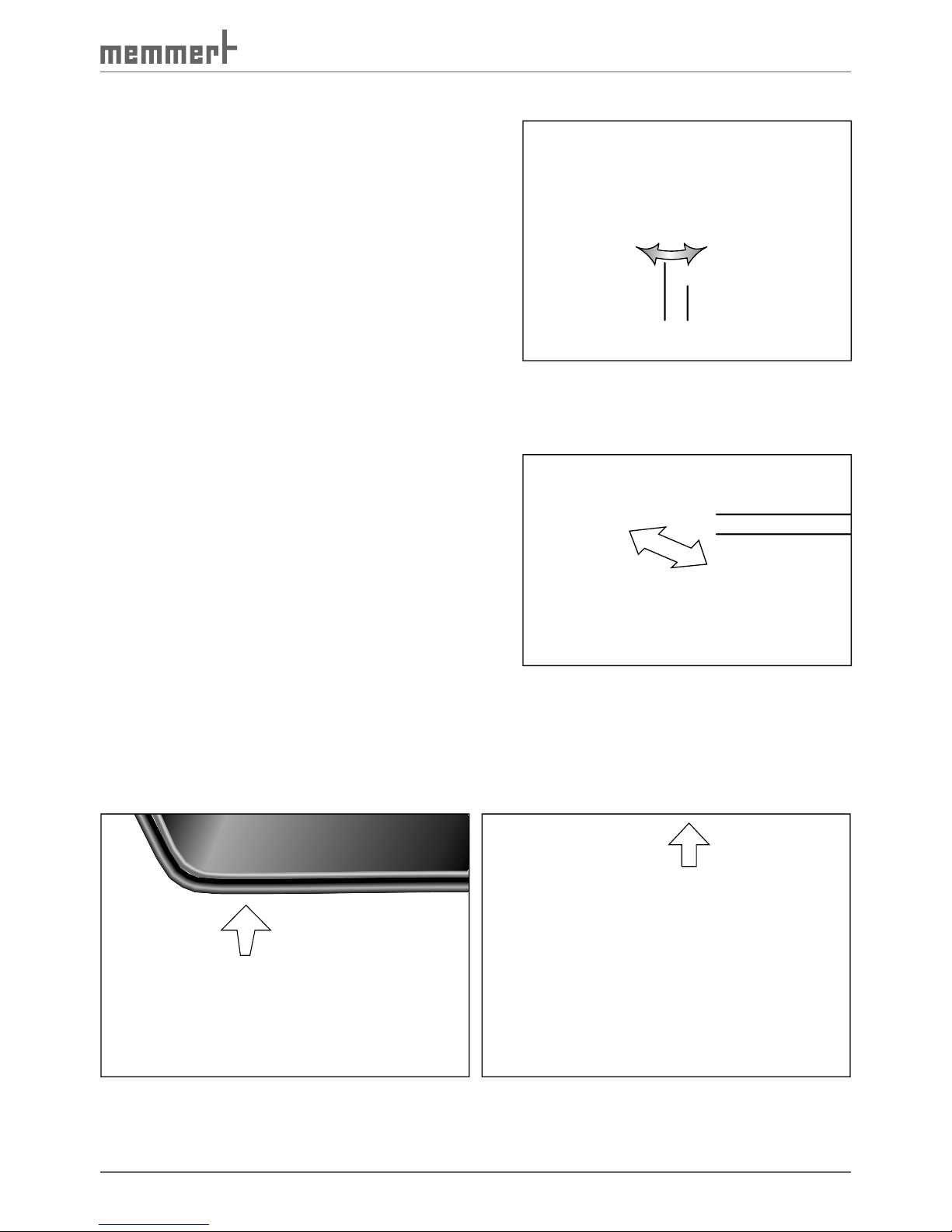
63
Maintenance and Servicing
8.4 Adjust door
A well-closing door is indispensable for temperature
and climatic test chambers. On Memmert
appliances, the tight closing of the door is
optimally guaranteed by a chamber seal and
door seal. In permanent operation, it is possible
that the flexible seal material will settle. To
ensure that the door closes exactly despite this,
an adjustment may be necessary:
1. Undo the grub screw with a Torx-TX8 tool
( Fig. 39 ). This is fixed with locking paint and
can be undone with a jolt.
2. Adjust door by turning the eccentric tappet
(2) with a screwdriver.
3. Tighten the grub screw again.
The locking plate ( Fig. 40 ) can also be adjusted:
1. Undo screws (1).
2. Move locking plate in direction of arrow.
3. Tighten the screws again.
8.5 Removing / cleaning the air
filter of the cooling unit
1. Open door
2. Remove and empty the drip tray ( Fig. 41 ).
3. Pull out the filter by the handle on the top
( Fig. 42 ).
4. Clean filter in a dishwasher or with a steam
cleaner.
5. Push the filter back in and reinsert the drip tray.
Fig. 41 Removing drip tray
Fig. 42 Pulling out air filter
12 12
Fig. 39 Adjusting the door
1 Grub screw
2 Eccentric
Fig. 40 Adjusting the locking plate
1 Undo screws
Page 64

64
Maintenance and Servicing
8.6 Replacing the interior lamps
1. Undo the four fixing screws of the glass plate
on the ceiling of the interior and remove the
glass plate ( Fig. 43 ).
2. Replace the defective lamp with a standard
new 25 watt halogen lamp.
3. Screw the glass plate back on. Make sure
that the seal is properly mounted.
8.7 Repairs and Service
Warning!
After removing covers, voltage-carrying parts may be exposed. You
may receive an electric shock if you touch these parts. Disconnect
the mains plug before removing any covers. Any work inside the
unit may only be performed by qualified electricians.
Repairs and service work are described in a separate service manual.
Fig. 43 Interior lighting
Page 65

65
Storage and disposal
9. Storage and disposal
9.1 Storage
The test chamber may only be stored under the following conditions.
► dry and in an enclosed, dust-free room
► frost-free
► disconnected from the power supply
Before storage, empty the freshwater and condensation water tanks (see page 22 ).
9.2 Disposal
This product is subject to the Directive 2002/96/EC on Waste Electrical
Electronic Equipment (WEEE) of the European Parliament and of the EU
Council of Ministers. This appliance has been brought to market after
August 13th, 2005 in countries which have already integrated this
directive into their national laws. It may not be disposed of in normal
household waste. To dispose, please contact your dealer or manufacturer. Any appliances that are infected, infectious or contaminated with
materials that are a hazard to health are excluded from being taken
back.
Please observe all other regulations in this context.
Note for Germany:
The appliance may not be left at public or communal recycling or collection points.
Page 66

66
Index
Index
A
Accidents 9
Acoustic signal 47
Adjust door 63
Air circulation 17
Air filter 62, 63
Air humidity 18
ALARM sound 47
Altitude of installation 18
Ambient temperature 18
Appliance errors 44
ASF 49
Automatic defrosting system
47, 54
Automatic temperature
monitor 49
B
Basic appliance settings 46
Basic equipment 13
Basic operation 29
C
Cable feed-through 26
Calibration 51
Card reader 59
CD-ROM 56
Celsius 55
Cleaning the air filter 63
Clearance 20
Clock time 46
Close command of the ramp
segment 37
Closing the door 25
Communication address 47
Communication interfaces
55
Compensation correction
values 47, 53
Condensation 62
Condensation water runoff
tube 62
Conformity 15
Connecting 23
Connections 18
Control 24
Controller 28
Conversions 8
Cool-down speed 12
Cooling /heating up speed
12, 13
Cooling unit 51
Current consumption 17
Customer service 2
D
Dangers 7
Date 47
Defrosting system 47, 54
Degree of protection 17
Delayed programme start 35
Delivery 19
Description 10
Design 10
Designation 16
Disposal 65
Disposing of packaging
material 19
Door 25
Drip tray 63
E
EC Declaration of Conform-
ity 15
Electrical equipment 17
Electronic temperature moni-
toring 48
Emergency 9
Ending operation 43
ENDSOUND 47
Environmental conditions 18
Error messages 44
Ethernet 56
Example of settings Week
time switch 34
Example setting Normal
mode 31
Example setting program-
ming mode 39
F
Flash memory 60
Freshwater tanks 22
Fuses 17
H
Heat compensation 12
Humidity calibration 53
Humidity operation 11
I
Icing 54
ID-LOCK 60
Installation 20
Intended Use 14
Interfaces 55
Interior lamps 64
IP address 56
Irregularities 8
J
K
Key icon 60
L
Labelling 7
Lamps 64
Language 47
Laptop 21, 43
Laptop holder 21
Load 17
Loading 26
Lock 60
Log memory 45, 57
M
Maintenance 61
Malfunctions 8, 44
Manufacturer 2
Material 14
Memory 57
MEMoryCard 58
MEMoryCard XL 58
Minimum clearance 20
Monitoring 17
Monitoring temperature 48
N
Nameplate 16
Network 56
Networking 55
Noise level 17
Normal mode 30
Page 67

67
Index
O
Opening and closing the
door 25
Operating modes 29
Operating mode - settings
30
Operating panel 28
Operating personnel 8
Operating staff 24
Operating voltage 17
Operation 24
P
PC 43
Performance 17
Power failure 45
Printer 46
Printout 57
Product safety 7
Programming mode 35
R
Ramp repeat function 38
Ramp segments 37
Read-write device 59
Regular maintenance 62
Repairs 64
Replacing the interior lamps
64
RS232 55
RS232/RS485 adapter 55
RS485 55
S
Safety class 17
Safety equipment 48
Safety Labelling 7
Safety regulations 6
Service 64
Servicing 61
SET-POINT WAIT 37
Setting parameters 29
Setting Up 19
Setup 46
Standard accessories 18
Storage 65
Storage after delivery 19
Storage space 59
Switching appliance on and
off 27
Switch-on time 36
System/ appliance errors 44
T
Tank drawer 22, 24
Tanks 22
Technical data 17
Temperature calibration 51
Temperature monitoring 48
Temperature operation 11
Temperature sensor 21, 48
Tolerance band ASF 47
Transport 19
Transport damage 19
TWW 48
U
Unpacking 19
USB interface 55
User-ID-Card 60
V
Volume 17
W
Warm-up speed 13
Warning message 51
Warning stickers 7
Water specifications 22
Weekday 47
Week time switch 33
Weight 17
Working range 12
X
XTADMIN 56
Y
Year 47
Page 68

Memmert GmbH + Co KG | Postfach 1720 | D-91107 Schwabach | Tel. +49 (0) 9122-925-0 | Fax +49 (0) 9122-145-85 | E-Mail: service@memmert.com | www.memmert.com
05/2017
CTC/TTC englisch
D10804
 Loading...