

Page 1

OPERATING MANUAL
CDP 115
Peltier cooling unit for waterbaths
Page 2

Manufacturer and customer service
Memmert GmbH + Co. KG
Willi-Memmert-Straße 90–96
D-91186 Büchenbach
Deutschland
Phone: +49 (0)9122 925-0
Fax: +49 (0)9122 14585
E-mail: sales@memmert.com
Internet: www.memmert.com
Customer service:
Service hotline: +49 (0)9171 9792 911
Service fax: +49 (0)9171 9792 979
E-mail: service@memmert.com
Shipping address for repairs:
Memmert GmbH + Co. KG
Kundenservice
Willi-Memmert-Str. 90-96
DE-91186 Büchenbach
Germany
Please contact our customer service before sending appliances for repair or before returning
equipment, otherwise, we have to refuse acceptance of the shipment.
© 2013 MEMMERT GmbH + Co. KG
Date 06/2013
We reserve the right to make changes
Page 3

Waterbath cooling unit CDP 115
About this manual
Purpose and target group
This manual describes the construction, function, assembly and operation of CDP 115 Peltier
cooling units for MEMMERT waterbaths. It is intended for use by trained personnel of the
operator, who have the task of assembling and/or operating the unit.
If you as the operator are asked to work on the unit, you should read this manual carefully
before starting work on the unit. Familiarise yourself with the safety regulations. Only perform
the work that is described in this manual. If there is something you don't understand, or
certain information is missing, ask your superior or get in touch with the manufacturer. Do not
do anything without authorisation.
This manual cannot describe all the possible combinations of setup and connection
variations. To make matters clearer, the assembly of two representative waterbaths is
described; the depictions may therefore differ slightly from the actual appearance. But
the assembly always follows the same pattern.
Other documents that you must read:
You should also consult the instruction manual for the waterbath on which the cooling unit is
to be operated.
Storage and Forwarding
This instruction manual belongs with the unit and should always be stored so that persons
working on the unit have access to it. It is the responsibility of the operator to ensure that
persons who work on or who will work on the unit are informed as to the whereabouts of
this instruction manual. We recommend that it is always stored in a protected location close
to the cooling unit. Make sure that the instruction manual is not damaged by heat or damp.
If the cooling unit or the waterbath is sold or transported and then set up again at a different
location, this instruction manual must also go with it.
3
Page 4

Waterbath cooling unit CDP 115
Contents
1. Safety regulations 5
2. Description 5
2.1 Overview .............................................................................................................................5
2.2 Function ............................................................................................................................... 6
2.3 Technical data ...................................................................................................................... 6
2.4 Intended use ........................................................................................................................ 7
3. Assembly and connection 7
3.1 Installation options .............................................................................................................. 7
3.2 Required accessories ..........................................................................................................7
3.3 Attachment on waterbath (only for waterbaths with gable lid) .................................. 9
3.3.1 Replacing lid of waterbath ............................................................................................. 9
3.3.2 Attaching the tube suspender to the waterbath .......................................................10
3.3.3 Attaching the cooling unit to the waterbath ............................................................. 11
3.3.4 Connecting the cooling unit......................................................................................... 13
3.4 Standalone unit ................................................................................................................. 14
4. Operation 15
4.1 Switching on and off .........................................................................................................15
4.2 In operation ....................................................................................................................... 15
4.3 Automatic switch-off ....................................................................................................... 15
4.4 Function test ..................................................................................................................... 15
4.5 Troubleshooting................................................................................................................. 15
4.6 Dismantling the cooling unit .......................................................................................... 16
5. Disposal 16
6. EC Declaration of Conformity 17
4
Page 5
1. Safety regulations
Warning!
After removing covers, current-carrying parts may be exposed.
You may get an electric shock if you touch these parts. Disconnect
the mains plug before removing any covers. Any work inside the
unit may only be performed by qualified electricians.
Warning!
If any fluid penetrates the housing this could cause electric shocks
and short circuits. Do not immerse the unit in water and protect it
from spray water.
Also observe the safety regulations and notes in the instruction manual for the
waterbath used.
2. Description
Waterbath cooling unit CDP 115
2.1 Overview
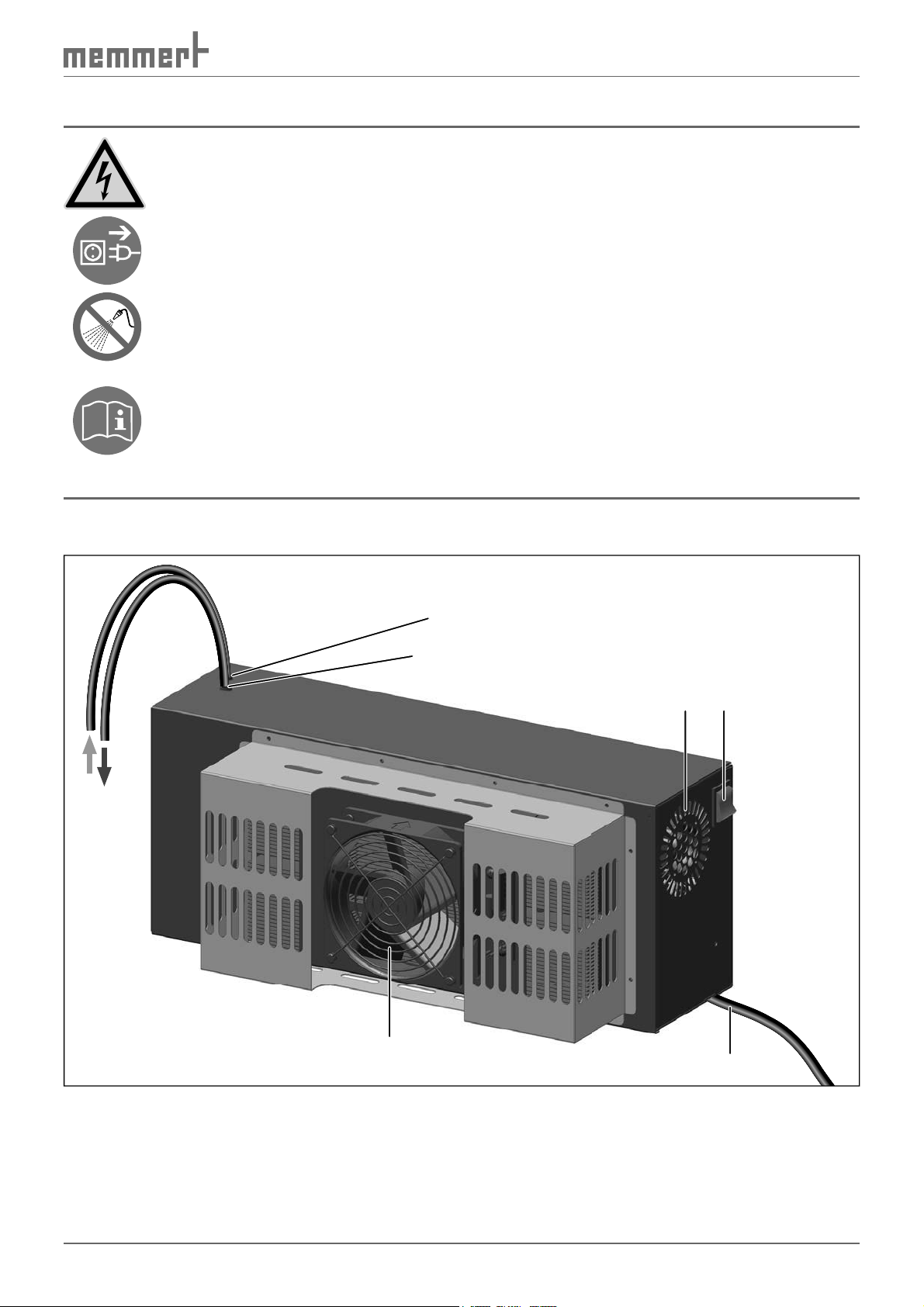
2
1
34
6
Fig. 1 Waterbath cooling unit CDP 115
1 Return tube to the waterbath
2 Supply tube from the waterbath
3 Housing fan
4 On/Off switch
5 Mains lead
6 Peltier cooling unit with fan
5
5
Page 6
Waterbath cooling unit CDP 115
2.2 Function
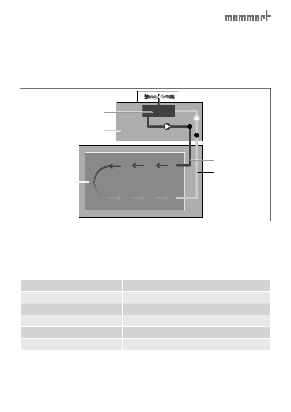
The waterbath cooling unit CDP 115 makes it possible to cool the water in Memmert waterbaths to temperatures below room temperature. To do this, water is pumped from the waterbath, cooled by a Peltier module and then returned to the waterbath (Fig. 2).
The cooling performance is constant and cannot be regulated. The temperature control of the
water is taken over by the waterbath; its controller automatically takes into account the cooling performance of the cooling unit.
3
2
4
1
Fig. 2 How the waterbath cooling unit CDP 115 works
1 MEMMERT waterbath
2 Waterbath cooling unit CDP 115
3 Peltier cooling unit
4 Water return from the cooling unit to the waterbath
5 Water supply from the waterbath to the cooling unit
2.3 Technical data
Dimensions W x H x D 450 x 185 x 120 mm
Weight 8 kg
Electrical connection 230 V/50 Hz
5
Current consumption max. 160 W
Effective refrigeration capacity (W) 115 W
Flow rate 600 ml/min
6
Page 7
Waterbath cooling unit CDP 115
2.4 Intended use
The waterbath cooling unit CDP 115 may only be operated in conjunction with Memmert waterbaths of types W..7, W..10, W..14, W..22, W..29 and W..45. You can determine which type
of waterbath you have from the nameplate on the waterbath.
The waterbath cooling unit CDP 115 may only be used for pumping and cooling water, and
may not be used with other liquids.
3. Assembly and connection
The operating location of the waterbath cooling unit should be chosen so that the fan
opening of the Peltier cooling element (see Fig. 1) remains as free as possible to achieve
the maximum cooling performance. The other two fan openings in the housing must
also remain uncovered.
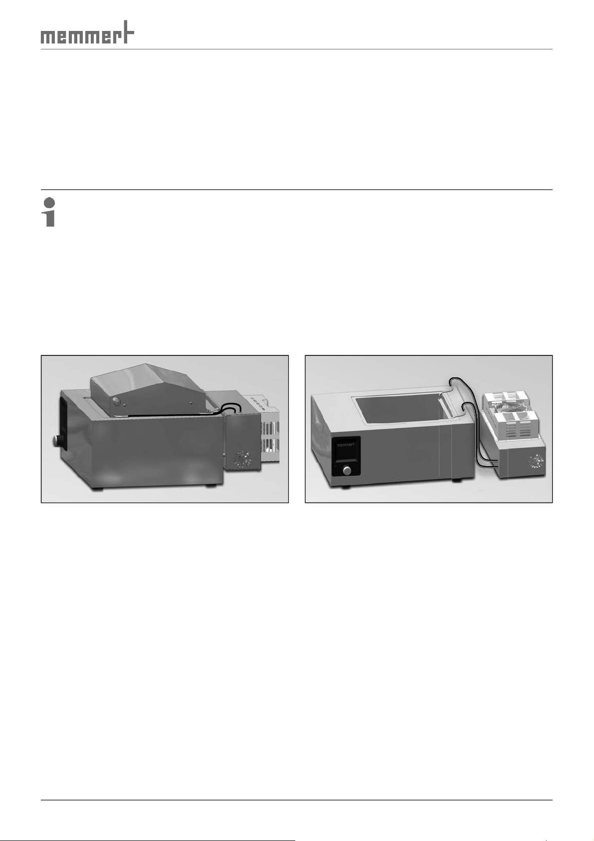
3.1 Installation options
The waterbath cooling unit CDP 115 can be installed in two ways; it can be
► attached to the waterbath (only for waterbaths with gable lids, Fig. 3;
assembly description from page 9)
► set up separately next to the waterbath (Fig. 4; assembly description from page 14).
Fig. 3 Cooling unit is fixed to the rear of
the waterbath
Fig. 4 Cooling unit standing next to the
waterbath
3.2 Required accessories
Various accessories are required to connect and assemble the waterbath cooling unit CDP 115.
What these are depends on the one hand on the installation method planned (fitted onto the
waterbath or separately, see Fig. 3 and Fig. 4) and on the other, on the waterbath type for
which the cooling unit is to be operated. (You can determine which type of waterbath you
have from its nameplate.)
All accessories are contained in a fixtures and connections set (not part of the delivery, see
Table 1). If you want to assemble the cooling unit on waterbaths with a gable lid, you will also
require a special lid with notches for the cooling tubes.
The following is an overview of the accessories available.
7
Page 8

Waterbath cooling unit CDP 115
I1/I2
CC2C1
B A
J1/J2
G/H/I/J
I1/I2
J1/J2
E D
Fig. 5 Available assembly accessories (for a description, see Table 1)
Accessories Includes
Tube suspender for waterbath W..7/10 A
Tube suspender for waterbath W..14/22 B
Tube suspender for waterbath W..29/45
Fixtures and
connection set
Special lid for W..7 G
Special lid for W..10 H
Special lid for W..14/22 with two closing panels and screws I, I1, I2
with intermediate rail and 3 screws
Fixing rail for attachment of cooling
unit to waterbath W..7/10/14/22
Fixing rail for attachment of cooling
unit to waterbath W..29/45
Item in
Fig. 5
C, C1, C2
D
E
Order No.
...-L9
...-L4*
Special lid for W..29/45 with two closing panels and screws J, J1, J2
Table 1 Overview of available accessories
* When ordering, please specify waterbath size
8
Page 9
Waterbath cooling unit CDP 115
The following overview illustrates which of these accessories you require for which installation
option:
Required accessories (see Table 1) for ...
Waterbath
model
W..7
W..10
W..14/22
W..29/45
Lid design
of waterbath
... Assembly on waterbath (see Fig. 3)
flat not possible A
sloping A D G –
flat not possible A
sloping A D H –
flat not possible B
sloping B D I –
flat not possible C
sloping C E J –
... Standalone unit
(see Fig. 4)
Table 2 Overview of required accessories
3.3 Attachment on waterbath
(only for waterbaths with gable lid)
3.3.1 Replacing lid of waterbath
In order for the cooling unit to be attached to the waterbath, the standard lid must be replaced with a special lid (G/H/I/J) (see Table 1 and Fig. 5).
1. Remove the supplied closing panels and
fixture material (I1/I2/J1/J2) from the
special lid I/J (only for special lids for
waterbaths W..14/22/29/45).
If the waterbath is to be operated
without a shaking device: Attach the
closing panel I1/J1 with two supplied
screws on the inside of the lid (Fig. 6).
(This is to prevent heat loss through the
side cut-out in the lid for the shaking
device.)
I1/J1
I/J
Fig. 6
Addition of closing panel when operating the
waterbath without shaker device
9
Page 10

Waterbath cooling unit CDP 115
C1C1
2. Unscrew the hinges of the original lid from the waterbath (Fig. 7); remove lid.
3. Pull the O-rings off the screws.
4. Place the special lid G/H/I/J onto the waterbath, push six screws through the hinges of the
lid and push the O-rings onto the screws (Fig. 8).
5. Screw the special lid tight to the waterbath.
G/H/I/J
1
2
Fig. 7 Unscrew standard lid from waterbath
3
4
Fig. 8 Screw the special lid tight to the
waterbath
1 Lid hinge
2 Screw
3 O-ring
4 Top side of waterbath
3.3.2 Attaching the tube suspender to the waterbath
For waterbaths of the type W..29 and W..45:
1. Insert the intermediate rail C1 from below behind the frame of the basin so that the rail
will stay between the frame and the basin (Fig. 9).
2. Screw tube suspender C with three supplied screws C2 onto the intermediate rail (Fig. 10).
CC
C1C1
C2C2
W..29/W..45
W..29/W..45
Fig. 9 Fix intermediate rail (C1) and tube
suspender (C) to the waterbath
10
Fig. 10 Tube suspender fixed to the waterbath
Page 11
Waterbath cooling unit CDP 115
For waterbaths of the type W..7, W..10, W..14 and W..22:
Place tube suspenders A and B onto the edge of the top right-hand side of the waterbath, as
illustrated in Fig. 11 and Fig. 12.
A/BA/B
W..7/10/14/22W..7/10/14/22
Fig. 11 Fix tube suspender (A or B) onto
waterbath
Fig. 12 Tube suspender fixed to the waterbath
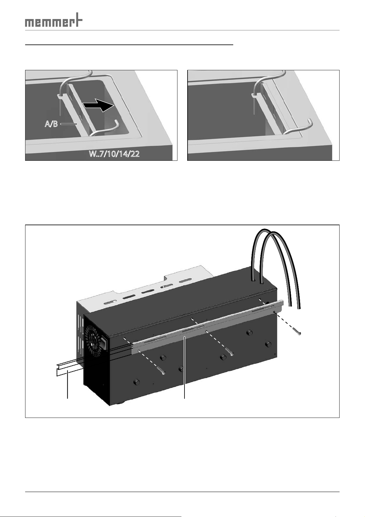
3.3.3 Attaching the cooling unit to the waterbath
1. Screw attachment rail D or E to the cooling unit with three screws, as shown in Fig. 13.
The attachment rail E must stick out in the direction of the mains switch.
D/EE
Fig. 13 Screw attachment rail to the cooling unit
11
Page 12

Waterbath cooling unit CDP 115
2. Attach cooling unit with the attachment rail on the rear of the waterbath into the bracket
on the hinges of the special lid (Fig. 14) and move horizontally (Fig. 15), so that the
bracket snaps into place (Fig. 16).
Fig. 14 Attach cooling unit with attachment rail on the rear of the waterbath into
the bracket on the hinges of the lid
Fig. 16 Retaining bracket of lid in place in
the attachment rail
Fig. 15 Push cooling unit forwards so that
the retaining bracket of the lid snaps into
place in the bracket (see Fig. 16)
Fig. 17 Assembly of cooling unit finished
12
Page 13

3.3.4 Connecting the cooling unit
Waterbath cooling unit CDP 115
1,5 cm
Fig. 18 Connecting tubes
1. Cut the tubes of the cooling unit to the
lengths actually required for connection to
the tube suspender. Do not confuse the
supply and return tubes when doing this
(markings on the tubes and Fig. 18): The
rear tube of the cooling unit must be
plugged onto the rear connection of the
tube suspender.
Keep the tubes as short as possible, but do
not bend them. Store any excess tube
material; it will still be required.
2. Plug tubes onto the connections of the tube
suspender (sticks out 1.5 cm, Fig. 18).
3. Push a sufficiently long piece of the cut off
tube material onto the suction tube in the
waterbath basin and cut it to size, so that it
sticks out about 1 cm beyond the edge of
the basin (Fig. 19).
4. Connect the mains lead of the cooling unit.
1 cm1 cm
Fig. 19 Place a piece of the cut off tube
material onto the suction tube and cut
to size
13
Page 14

Waterbath cooling unit CDP 115
3.4 Standalone unit
1. Fix tube suspenders (A/B/C) to the waterbath as described in section 3.3.2 on page 10.
2. Place cooling unit to the right of the waterbath, as shown in Fig. 20. Make sure that the
cooling unit is standing on its rubber feet when this is done (Peltier fan is facing upwards,
the mains switch is facing to the rear).
3. Cut the tubes of the cooling unit to the lengths actually required for connection to the
tube suspender. Do not confuse the supply and return tubes when doing this (markings
on the tubes and Fig. 20): The upper tube of the cooling unit must be plugged onto the
rear connection of the tube suspender A/B/C.
Keep the tubes as short as possible, but do not bend them. Store any excess tube material;
it will still be required.
4. Plug tubes onto the connections of the tube suspender (sticks out 1.5 cm, Fig. 20).
5. Push a sufficiently long piece of the cut off tube material onto the suction tube in the
waterbath basin and cut it to size, so that it sticks out about 1 cm beyond the edge of the
basin (Fig. 19).
6. Connect the mains lead of the cooling unit.
A/B/CA/B/C
1,5 cm
Fig. 20 Cooling unit standing next to the waterbath
14
Page 15

Waterbath cooling unit CDP 115
4. Operation
There must not be any coarse-grained particles in the waterbath. This could damage the
cooling unit.
4.1 Switching on and off
► To start operating, switch on the cooling unit
on the mains switch (Fig. 21).
► Use the mains switch to switch off the cool-
ing unit.
You can see that the unit is on if the fan is
turning. If the fan is not turning, the automatic
switch-off has probably been triggered (see
section 4.3).
Fig. 21 Mains switch
4.2 In operation
The refrigeration capacity is constant and cannot be regulated. The cooling unit works at a
constant power as long as it is switched on. The temperature control of the water is taken
over by the waterbath; its controller automatically takes into account the cooling performance
of the cooling unit.
Do not operate the cooling unit when the waterbath heater is switched off. This could trigger
the automatic switch-off (see next section).
If the water in the waterbath is to be heated up to above room temperature, it is recommended that you switch the cooling unit off.
4.3 Automatic switch-off
The cooling unit has a low temperature fuse which switches off the unit automatically when
the water temperature is at about 3 ºC, to prevent icing and possible damage to the cooling
element. When the water temperature reaches about 5 ºC, the cooling unit switches back on
again.
4.4 Function test
► You can see that the unit is on, and that the Peltier element is cooling, if the fan is turning.
► To check that the unit is pumping, pull off the suction tube from the tube suspender and
place a finger on it to test for suction. If there is no suction effect: See next section, Troubleshooting.
15
Page 16
Waterbath cooling unit CDP 115
4.5 Troubleshooting
► Is the unit connected to the mains supply? If not, connect unit to the mains.
► Is the unit switched on? If not, switch unit on.
► Are all tubes correctly connected? If not, connect tubes.
► Is the waterbath heater switched on? If not, switch waterbath heater on.
► It is possible that the tubes in the tube suspender are blocked. In this case, replace the
tube suspender.
If the error cannot be eliminated, the cause is probably a defect in the unit. In this case you
should contact customer service (see page 2).
4.6 Dismantling the cooling unit
1. Switch off the cooling unit; pull out the
mains plug.
2. Remove the tube suspender from the water-
bath. Keep the tubes in place when doing
this.
I1/J1I1/J1
3. Attach the closing panel I1/J1 with two sup-
plied screws on the right side of the inside of
the lid (Fig. 22). (This is to prevent heat loss
through the cut-out in the lid for the tube
suspender.)
The waterbath can now be used again without
the cooling unit.
Fig. 22 Assemble the closing panel
5. Disposal
Have the unit disposed of as scrap metal by a specialist disposal company.
16
Page 17
6. EC Declaration of Conformity
EC Declaration of Conformity
Manufacturer´s name and address: MEMMERT GmbH + Co. KG
Äußere Rittersbacher Straße 38
D-91126 Schwabach
Product: Peltier cooling unit
Type: CDP
Sizes: 115
Nominal voltage: AC 230 V 50/60 Hz
alternative AC 115 V 50/60 Hz
The designated product is in conformity with the European EMC-Directive
2004/108/EEC
including amendments
Council Directive of 03 May 1989 on the approximation of the laws of the Member States relating to
Full compliance with the standards listed below proves the conformity of the designated product with the essential
protection requirements of the above-mentioned EC Directive:
DIN EN 61326-1:2006-10 EN 61326-1:2006
DIN EN 61000-3-11:2001-04 EN 61000-3-11 :2000
The designated product is in conformity with the European Low Voltage Directive
Council Directive on the approximation of the laws of the Member States relating to Electrical
Full compliance with the standards listed below proves the conformity of the designated product with the essential
protection requirements of the above-mentioned EC Directive:
DIN EN 61 010-1 (VDE 0411 part 1):2002-08 EN 61 010-1:2001
DIN EN 61 010-2-010 (VDE 0411 part 2-010):2004-06 EN 61 010-2-010:2003
Schwabach, 03.06.09
equipment for use within certain voltage limits.
______________________________
(Legally binding signature of the issuer)
This declaration certifies compliance with the above mentioned directives but does not include a property assurance. The
safety note given in the product documentation which are part of the supply, must be observed.
electromagnetic compatibility.
2006/95/EEC
including amendments
Waterbath cooling unit CDP 115
Modelljahr 2009 D10793 / 03.06.09
17
Page 18

Page 19

Page 20

Memmert GmbH + Co KG | Postfach 1720 | D-91107 Schwabach, Germany | Tel. +49 (0) 9122-925-0 | Fax +49 (0) 9122-145-85 | Email: service@memmert.com | www.memmert.com
19.06.2013
CDP englisch
D10810
 Loading...